Cyclades ACS 3.2.0 Installation/Administration/User...
210
Installation/Administration/User Guide Cyclades ® ACS
Transcript of Cyclades ACS 3.2.0 Installation/Administration/User...
Installation/Administration/User Guide
For Technical Support:
www.avocent.com/support
590-660-501C
Cyclades® ACS
FCC Warning Statement
The Cyclades ACS advanced console server has been tested and found to comply with the limits for Class A digital devices, pursuant to Part 15 of the FCC rules. These limits are designed to provide reasonable protection against harmful interference when the equipment is operated in a commercial environment.
This equipment generates, uses and can radiate radio frequency energy and, if not installed and used in accordance with the Installation and Service Manual, may cause harmful interference to radio communications.
Operation of this equipment in a residential area is likely to cause harmful interference in which case the user is required to correct the problem at his or her own expense.
Notice about FCC Compliance for All Cyclades ACS Advanced Console Server Models
To comply with FCC standards, the Cyclades ACS advanced console server requires the use of a shielded CAT 5 cable for the Ethernet interface. Notice that this cable is not supplied with either of the products and must be provided by the customer.
Canadian DOC Notice
The Cyclades ACS advanced console server does not exceed the Class A limits for radio noise emissions from digital apparatus set out in the Radio Interference Regulations of the Canadian Department of Communications.
L’Cyclades ACS advanced console server n’émete pas de bruits radioélectriques dépassant les limites applicables aux appareils numériques de la classe A prescrites dans le règlement sur le brouillage radioélectrique edicté par le Ministère des Communications du Canada.
Safety and EMC Approvals and Markings
FCC Part 15 A, ICES-003, C-Tick, VCCI Class A, BSMI Class A, MIC Class A, CE (EN55022 Class A, EN55024, EN60950-1), GS, CB, CSA/UL 60950-1, Solaris Ready™, NEBS for ACS 16 NEBS and ACS 32 NEBS with single or dual DC power supplies
Cyclades® ACS Advanced Console ServerInstallation/Administration/User Guide
Avocent, the Avocent logo, The Power of Being There, DSView and Cyclades are registered trademarks of Avocent Corporation or its affiliates. All other marks are the property of their respective owners.
© 2007 Avocent Corporation. All rights reserved. 590-660-501C
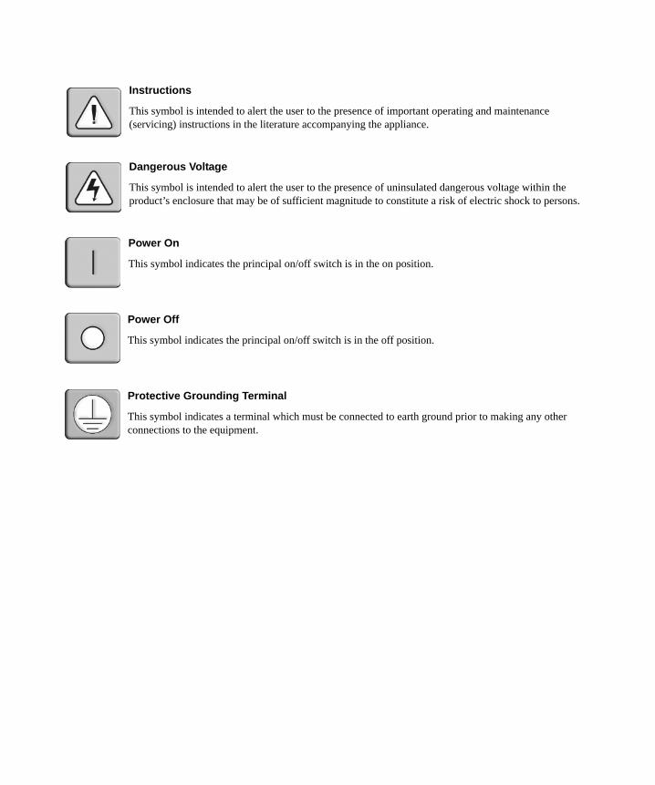
Instructions
This symbol is intended to alert the user to the presence of important operating and maintenance (servicing) instructions in the literature accompanying the appliance.
Dangerous Voltage
This symbol is intended to alert the user to the presence of uninsulated dangerous voltage within the product’s enclosure that may be of sufficient magnitude to constitute a risk of electric shock to persons.
Power On
This symbol indicates the principal on/off switch is in the on position.
Power Off
This symbol indicates the principal on/off switch is in the off position.
Protective Grounding Terminal
This symbol indicates a terminal which must be connected to earth ground prior to making any other connections to the equipment.
iii
Table of ContentsList of Tables.................................................................................................................. vii
List of Figures ................................................................................................................. xi
Chapter 1: Introduction ................................................................................................... 1
Overview ............................................................................................................................................ 1Connectors on the ACS Console Server ............................................................................................ 1Accessing the ACS Console Server and Connected Devices ............................................................. 2Web Manager..................................................................................................................................... 2Prerequisites for Using the Web Manager ........................................................................................ 3Types of Users.................................................................................................................................... 3Security .............................................................................................................................................. 3Authentication .................................................................................................................................... 4IPv6.................................................................................................................................................... 5
Services not supporting IPv6 ...................................................................................................... 5VPN.................................................................................................................................................... 5Packet Filtering ................................................................................................................................. 6
Structure of IP filtering............................................................................................................... 6Add rule and edit rule options .................................................................................................... 7
SNMP ................................................................................................................................................. 8Notifications, Alarms and Data Buffering ......................................................................................... 8
Syslog servers ............................................................................................................................. 8Managing Users of Connected Devices............................................................................................. 9
Configuring access to connected devices ................................................................................... 9ACS Console Server and Power Management .................................................................................. 9
Configuring power management .............................................................................................. 11Options for managing power .................................................................................................... 11
Hostname Discovery ........................................................................................................................ 12
Chapter 2: Installation ................................................................................................... 13
Important Pre-installation Requirements ........................................................................................ 13Basic Installation Procedures.......................................................................................................... 13
Making an Ethernet connection................................................................................................ 14
TABLE OF CONTENTS
iv Cyclades ACS Advanced Console Server Installation/Administration/User Guide
Making a direct connection to configure the network parameters........................................... 14Powering up the console server and the connected devices..................................................... 15Performing basic network configuration using the wiz command ........................................... 15Adding users and configuring ports using the Web Manager .................................................. 19
Other Methods of Accessing the Web Manager............................................................................... 20Installing PC Cards ......................................................................................................................... 20Connecting Cyclades PM IPDUs .................................................................................................... 21
Chapter 3: Web Manager for Regular Users................................................................ 23
Using the Web Manager .................................................................................................................. 23Features of Regular User Forms ..................................................................................................... 24Connect ............................................................................................................................................ 24
Connect to the console server................................................................................................... 25Connect to serial ports ............................................................................................................. 25Connection protocols for serial ports....................................................................................... 26
IPDU Power Management............................................................................................................... 27Outlets Manager ....................................................................................................................... 27Outlets Group Ctrl.................................................................................................................... 28View IPDU info......................................................................................................................... 28
Security ............................................................................................................................................ 30
Chapter 4: Web Manager for Administrators............................................................... 31
Common Tasks for ACS Console Server Administrators................................................................. 31Common Features of Administrator Forms..................................................................................... 32Logging Into the Web Manager ....................................................................................................... 33Overview of Administrative Modes.................................................................................................. 34
Wizard mode ............................................................................................................................. 34Expert mode .............................................................................................................................. 35
Chapter 5: Configuring the ACS Console Server in Wizard Mode ............................ 37
Step 1: Security Profile .................................................................................................................... 37Step 2: Network Settings .................................................................................................................. 41Step 3: Port Profile .......................................................................................................................... 43Step 4: Access .................................................................................................................................. 44Step 5: Data Buffering ..................................................................................................................... 47
Table of Contents v
Step 6: System Log.................................................................................................................... 50
Chapter 6: Applications................................................................................................. 53
Configuring the Console Server in Expert Mode............................................................................. 53Overview of menus and forms................................................................................................... 53
Applications Menu and Forms......................................................................................................... 55Connect ..................................................................................................................................... 55IPDU Power Management ....................................................................................................... 56Applications - IPDU Power Mgmt. - Outlets Group Ctrl......................................................... 59Applications - IPDU Power Mgmt. - View IPDUs Info............................................................ 60Applications - IPDU Power Mgmt. - Configuration ................................................................ 62Applications - IPDU Power Mgmt. - Software Upgrade.......................................................... 63
Expert - Applications - PMD Configuration.................................................................................... 64Applications - PMD Configuration- General ........................................................................... 64Applications - PMD Configuration- Outlet Groups ................................................................. 65Applications - PMD Configuration- Users Management......................................................... 66
Expert - Applications - Terminal Profile Menu ............................................................................... 69
Chapter 7: Network Menu and Forms .......................................................................... 71
Host Settings .................................................................................................................................... 72General host settings ................................................................................................................ 72Disabling and enabling IPv4 or IPv6 protocols....................................................................... 73IPv4 settings.............................................................................................................................. 74IPv6 settings.............................................................................................................................. 75
Syslog ............................................................................................................................................... 79PCMCIA Management..................................................................................................................... 80VPN Connections ............................................................................................................................. 89SNMP ............................................................................................................................................... 93Firewall Configuration .................................................................................................................... 97Host Table...................................................................................................................................... 106Static Routes .................................................................................................................................. 107
Chapter 8: Security Menu and Forms ........................................................................ 111
Users and Groups .......................................................................................................................... 111Active Ports Sessions ..................................................................................................................... 114Authentication ................................................................................................................................ 115
vi Cyclades ACS Advanced Console Server Installation/Administration/User Guide
Configuring authentication for console server logins ............................................................ 115Security Profiles............................................................................................................................. 122
Security certificates ................................................................................................................ 126
Chapter 9: Ports Menu and Forms ............................................................................. 129
Physical Ports ................................................................................................................................ 129Virtual Ports .................................................................................................................................. 150Ports Status .................................................................................................................................... 153Ports Statistics ............................................................................................................................... 154Expert - Ports - Hostname Discovery ............................................................................................ 155
Chapter 10: Administration Menu and Forms ........................................................... 157
System Information ........................................................................................................................ 157Notifications................................................................................................................................... 158Time/Date....................................................................................................................................... 162Boot Configuration ........................................................................................................................ 164Backup Configuration.................................................................................................................... 166Upgrade Firmware ........................................................................................................................ 168Reboot ............................................................................................................................................ 169Online Help.................................................................................................................................... 169
Appendices................................................................................................................... 173
Appendix A: Technical Specifications ........................................................................................... 173Appendix B: Safety, Regulatory and Compliance Information...................................................... 174Appendix C: Technical Support ..................................................................................................... 182
Index.............................................................................................................................. 183
vii
List of TablesTable 1.1: ACS Console Server Connectors ...................................................................................... 2
Table 1.2: Authentication Methods Supported .................................................................................. 4
Table 1.3: Add Rule and Edit Rule Option Definitions ..................................................................... 7
Table 1.4: TCP Protocol Option Definitions..................................................................................... 7
Table 1.5: Common Administrator Tasks for Configuring Software................................................. 9
Table 2.1: ACS Console Server Serial Port Pin-out........................................................................ 15
Table 2.2: Tasks Related to Connecting Cyclades IPDUs .............................................................. 21
Table 3.1: Description of Regular User Web Interface................................................................... 24
Table 3.2: Java Applet Buttons for Connecting to the Console Server ........................................... 25
Table 3.3: Available Serial Port Protocols ..................................................................................... 26
Table 3.4: Regular User - Outlet Management Buttons .................................................................. 27
Table 3.5: Power Management Display Information by Configured Port ...................................... 29
Table 4.1: Administrator - Common Administrative Tasks ............................................................. 31
Table 4.2: Description of Administrator Web Manager Buttons..................................................... 32
Table 4.3: Administrator - Options for Trying, Saving and Restoring Configuration Change....... 33
Table 4.4: Administrator - Logout Button and Other Information in the Upper Right ................... 33
Table 5.1: Wizard - Serial Port Enabled Services for Each Security Profile.................................. 38
Table 5.2: Wizard - Serial Port Enabled Services for Each Security Profile.................................. 38
Table 5.3: Wizard - Enabled Protocols for Each Security Profile .................................................. 38
Table 5.4: Port Profile Setup Options ............................................................................................. 43
Table 5.5: Wizard - Add User Dialog: Field Names and Definitions ............................................. 46
Table 5.6: Wizard - Data Buffering Field Names and Definitions .................................................. 49
Table 5.7: Differences Beween Remote and Local Data Buffering ................................................. 49
Table 6.1: Expert Mode Screen Elements........................................................................................ 54
Table 6.2: Expert - Outlets Manager Icons Description ................................................................. 58
Table 6.3: Expert - Outlet Groups Ctrl Information ....................................................................... 60
LIST OF TABLES
viii Cyclades ACS Advanced Console Server Installation/Administration/User Guide
Table 6.4: Expert - Applications - Ipdu Power Mgmt - View IPDUs Info Description................... 61
Table 6.5: IPDU Power Mgmt Configuration Description ............................................................. 62
Table 6.6: Conventions Used in Specifying Outlets for User Accessibility..................................... 67
Table 6.7: Outlet Designations on Daisy-chained IPDUs (PM10 shown)...................................... 68
Table 6.8: Methods for Specifying a Specific Port on Daisy-chained IPDUs................................. 69
Table 7.1: Expert - Network Menu Descriptions ............................................................................. 71
Table 7.2: Network - Host Settings General Tab Form Field ......................................................... 72
Table 7.3: Network - Host Setting - IPv4 Field Defintions ............................................................. 75
Table 7.4: Network - Host Setting - IPv6 Field Defintions ............................................................. 76
Table 7.5: Modem Dialog Box Fields.............................................................................................. 82
Table 7.6: ISDN Dialog Box Fields................................................................................................. 83
Table 7.7: GSM Dialog Box Fields ................................................................................................. 84
Table 7.8: Ethernet Dialog Box Fields ............................................................................................ 85
Table 7.9: CompactFlash / Hard Drive Dialog Box Fields ............................................................ 86
Table 7.10: Wireless LAN Dialog Box Fields.................................................................................. 87
Table 7.11: CDMA Dialog Box Fields ............................................................................................ 88
Table 7.12: Field and Menu Options for Configuring a VPN Connection...................................... 91
Table 7.13: Expert - Fields and Menu Options for SNMP Configuration ...................................... 95
Table 7.14: Expert - TCP Options Fields ...................................................................................... 101
Table 7.15: UDP Options .............................................................................................................. 101
Table 7.16: Expert - Firewall Configuration Input/Output Interface and Fragments Fields ....... 102
Table 7.17: Expert - Target LOG Options Selection Fields .......................................................... 103
Table 7.18: Reply Packet Names and Definitions ......................................................................... 104
Table 7.19: Routing Type Fields in the New/Modify Route Dialog Box ....................................... 108
Table 8.1: Expert - Add User Dialog Field Names and Definitions.............................................. 112
Table 8.2: Expert - Active Ports Sessions Information.................................................................. 114
Table 8.3: Tasks for Setting up Authentication Servers................................................................. 116
Table 8.4: Enabled Services to Access the Console Server Under Each Security Profile ........... 123

List of Tables ix
Table 8.5: Enabled Services to Access the Serial Ports Under Each Security Profile.................. 123
Table 8.6: Enabled Protocols for Each Security Profile Shown with a Check Mark.................... 124
Table 9.1: Connections Protocols When Serial Port is Connected to Device Console Port ........ 131
Table 9.2: Available Connection Protocols When Terminal is Connected to a Serial Port ......... 132
Table 9.3: Connection Protocols for Modems or IPDUs. ............................................................. 133
Table 9.4: Access Form Menu and Fields ..................................................................................... 137
Table 9.5: Expert - Authentication Methods and Fallback Mechanisms ...................................... 138
Table 9.6: List of Authentication Method Procedures................................................................... 139
Table 9.7: Data Buffering Form Fields ......................................................................................... 141
Table 9.8: Expert - Multi User Form Fields.................................................................................. 143
Table 9.9: Available Options from the Allow Multiple Sessions Pull-down ................................. 143
Table 9.10: Expert - Power Management Form Fields................................................................. 144
Table 9.11: Other Form Fields...................................................................................................... 147
Table 9.12: New/Modify Port Dialog Box Fields. ......................................................................... 151
Table 9.13: Expert - Port Status Read-Only Form........................................................................ 154
Table 9.14: Expert - Ports-Port Status Read-Only Form.............................................................. 154
Table 9.15: Expert - Ports - Hostname Discovery Fields.............................................................. 155
Table 10.1: System Information Form........................................................................................... 157
Table 10.2: Notifications Form Fields .......................................................................................... 158
Table 10.3: Email Notifications Dialog Box Fields ...................................................................... 159
Table 10.4: Pager Notification Add/Edit Dialog Box Fields......................................................... 160
Table 10.5: SNMP Trap Notifications Add/Edit Dialog Box Fields.............................................. 161
Table 10.6: Boot Configuration Form Fields ................................................................................ 165
Table 10.7: Backup Configuration Settings if Using FTP Server ................................................. 166
Table 10.8: Backup Configuration if Using Storage Device ......................................................... 167
Table 10.9: Expert - Upgrade Firmware Form Fields .................................................................. 168
Table A.1: ACS Console Server Product Specifications................................................................ 173

x Cyclades ACS Advanced Console Server Installation/Administration/User Guide
xi
List of FiguresFigure 1.1: Front of the ACS Console Server ................................................................................ 1Figure 1.2: ACS Console Server Connectors ................................................................................. 1Figure 2.1: Placement of Mounting Brackets (Forward Mounting Configuration Shown) ......... 13Figure 2.2: Configuration Wizard Screen. ................................................................................... 16Figure 2.3: Current Configuration Wizard Screen for Option 0 (IPv4 Enabled) ........................ 17Figure 3.1: Regular User Form.................................................................................................... 24Figure 3.2: Regular User - IPDU Power Mgmt. Form ................................................................ 27Figure 3.3: Regular User - IPDU Power Mgmt. - Outlet Groups Ctrl ........................................ 28Figure 3.4: Regular User - View IPDUs Info............................................................................... 29Figure 4.1: Administrator - Web Manager Buttons ..................................................................... 32Figure 4.2: Example of Web Manager Form in Wizard Mode..................................................... 35Figure 4.3: Example of Web Manager Form in Expert Mode...................................................... 36Figure 5.1: Administrator - Physical Ports Factory Settings....................................................... 39Figure 5.2: Wizard - Step 1: Security Profile Form ..................................................................... 40Figure 5.3: Custom Security Profile Dialog Box ......................................................................... 41Figure 5.4: Wizard - Step 2: Network Settings - DHCP Disabled ............................................... 42Figure 5.5: Wizard - Step 2: Network Settings - DHCP Enabled ................................................ 42Figure 5.6: Wizard - Step 3: Port Profile ..................................................................................... 43Figure 5.7: Wizard - Step 4: Access ............................................................................................. 45Figure 5.8: Wizard - Step 4: Access Add User Dialog Box.......................................................... 45Figure 5.9: Wizard - Step 4: Change Password Dialog Box........................................................ 46Figure 5.10: Wizard - Step 5: Data Buffering [Local]................................................................. 48Figure 5.11: Wizard - Step 5: Data Buffering [Remote] .............................................................. 48Figure 5.12: Wizard - Step 6: System Log.................................................................................... 50Figure 6.1: Expert Mode Screen Elements ................................................................................... 54Figure 6.2: Expert - SSH session Java Applet.............................................................................. 55Figure 6.3: Expert - Applications - IPDU Power Mgmt. - Outlets Manager............................... 57Figure 6.4: Expert - Applications - IPDU Power Mgmt. - Outlets Manager - Show Outlets ...... 58Figure 6.5: Expert - Applications - IPDU Power Mgmt - Outlet Groups Ctrl............................. 60Figure 6.6: IPDU Power Mgmt. - View IPDUs Info. ................................................................... 61Figure 6.7: Expert - Applications - IPDU Power Mgmt. - Configuration ................................... 62
LIST OF FIGURES
xii Cyclades ACS Advanced Console Server Installation/Administration/User Guide
Figure 6.8: Applications - PMD Configuration ........................................................................... 65Figure 6.9: PMD Configuration - Outlet Groups......................................................................... 65Figure 6.10: PMD Configuration - Users Management .............................................................. 66Figure 6.11: Various Outlet Designations on Daisy-chained IPDUs .......................................... 68Figure 6.12: Expert - Applications - Terminal Profile Menu....................................................... 69Figure 6.13: Expert - Terminal Profile Menu Example .............................................................. 70Figure 7.1: Expert - Network - Host Settings ............................................................................... 72Figure 7.2: Expert - Network - Host Settings - IPv4 (DHCP disabled) ....................................... 74Figure 7.3: Expert - Network - Host Settings - IPv6 .................................................................... 75Figure 7.4: Expert - Network - Syslog .......................................................................................... 79Figure 7.5: Expert - Network - PCMCIA Management................................................................ 80Figure 7.6: PC Card Type by Slot ................................................................................................ 81Figure 7.7: Expert - CompactFlash/Hard Disk PC Card Configuration Dialog Box ................ 86Figure 7.8: Expert - Wireless LAN PC Card Configuration Dialog Box.................................... 87Figure 7.9: Expert - VPN New/Modify Connection Dialog Box .................................................. 90Figure 7.10: Security Custom Profile Dialog............................................................................... 92Figure 7.11: Expert - Network - SNMP....................................................................................... 94Figure 7.12: Expert - New/Mod SNMP v1 v2 Configuration Dialog Box................................... 95Figure 7.13: Expert - New/Mod SNMP v3 Configuration Dialog Box ........................................ 96Figure 7.14: Expert - Network - Firewall Configuration ............................................................. 97Figure 7.15: Expert - Firewall Configuration Edit Chain Dialog Box ....................................... 98Figure 7.16: Firewall Configuration User-defined Chain Message ............................................ 98Figure 7.17: Expert - Firewall Configuration Add Chain Dialog Box ........................................ 98Figure 7.18: Firewall Configuration Edit Rules for chain_name Form ..................................... 99Figure 7.19: Firewall Configuration Edit Rules for chain_name Buttons................................... 99Figure 7.20: Expert - Firewall Configuration Add Rule and Edit Rule Dialog Boxes ................ 99Figure 7.21: Firewall Configuration TCP Protocol Fields and Menu Options......................... 100Figure 7.22: Firewall Configuration Add Rule and Edit Rule UDP Protocol Fields................ 101Figure 7.23: Input/Output Interface Fields and Fragments Menu Options ............................... 102Figure 7.24: Firewall Configuration Add Rule and Edit Rule LOG Target Fields ................... 103Figure 7.25: Firewall Configuration Add Rule and Edit Rule REJECT Target Menu Options. 103Figure 7.26: Edit Chain Dialog Box .......................................................................................... 105Figure 7.27: Expert - Network - Host Tables ............................................................................ 106Figure 7.28: Expert - Network - Static Routes .......................................................................... 107Figure 7.29: Expert - Static Routes Add and Edit Dialog Boxes - Default Route..................... 107

List of Figures xiii
Figure 7.30: Expert - Static Routes Add and Edit Dialog Boxes - Network Route ................... 108Figure 7.31: Expert - Static Routes Add and Edit Dialog Boxes - Host Route ......................... 108Figure 8.1: Expert - Security - Users and Groups Form............................................................ 111Figure 8.2: Expert - Security - Active Ports Sessions................................................................. 114Figure 8.3: Expert - Security - Authentication ........................................................................... 115Figure 8.4: Expert - Security - Authentication - LDAP.............................................................. 119Figure 8.5: Expert - Administration - Time/Date ...................................................................... 121Figure 8.6: Expert - Security - Authentication - Kerberos ......................................................... 121Figure 8.7: Expert - Security - Authentication - NIS .................................................................. 122Figure 8.8: Expert - Security - Security Profile......................................................................... 122Figure 8.9: Expert - Physical Ports Default Factory Settings .................................................. 125Figure 8.10: Serial Ports Protocol Incompatibility Dialog Box ................................................ 125Figure 8.11: Custom Security Profile Dialog Box .................................................................... 126Figure 9.1: Ports - Physical Ports.............................................................................................. 129Figure 9.2: Ports - Physical Ports - General Form ................................................................... 130Figure 9.3: Ports - Physical Ports - Data Buffering Enabled .................................................... 140Figure 9.4: Ports - Physical Ports - Power Management, Enable IPMI Checked..................... 144Figure 9.5: Ports - Physical Ports - Power Management-Allow All Users ............................... 147Figure 9.6: Ports - Physical Ports -Power Management -Allow Users and Groups ................. 147Figure 9.7: Ports - Virtual Ports ................................................................................................ 150Figure 9.8: Ports - Virtual Ports - New/Modify Port Dialog Box .............................................. 151Figure 9.9: Ports - Virtual Ports - New/Modify Port Dialog Box .............................................. 152Figure 9.10: Ports - Virtual Ports - New/Modify - Port Names Dialog box .............................. 153Figure 9.11: Ports - Ports Status (Read-Only)........................................................................... 153Figure 9.12: Ports - Port Statistics (Read-Only)........................................................................ 154Figure 10.1: Expert - Administration - Time/Date .................................................................... 162Figure 10.2: Expert - Administration - Time and Date - NTP Enable ...................................... 163Figure 10.3: Expert - Administration - Time/Date - Edit Custom.............................................. 164Figure 10.4: Expert - Administration - Online Help .................................................................. 170

xiv Cyclades ACS Advanced Console Server Installation/Administration/User Guide
1
CHAPTER
1 Introduction
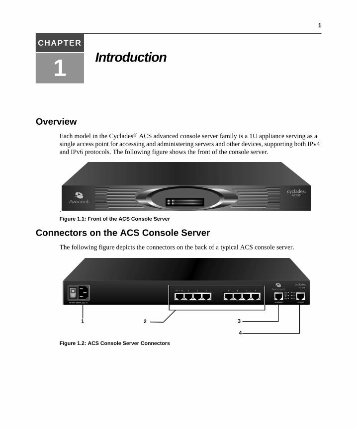
OverviewEach model in the Cyclades® ACS advanced console server family is a 1U appliance serving as a single access point for accessing and administering servers and other devices, supporting both IPv4 and IPv6 protocols. The following figure shows the front of the console server.
.Figure 1.1: Front of the ACS Console Server
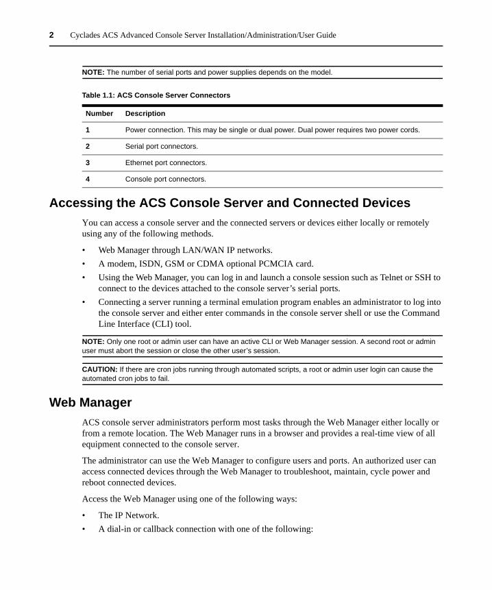
Connectors on the ACS Console ServerThe following figure depicts the connectors on the back of a typical ACS console server.
Figure 1.2: ACS Console Server Connectors
3
4
1 2
2 Cyclades ACS Advanced Console Server Installation/Administration/User Guide
NOTE: The number of serial ports and power supplies depends on the model.
Accessing the ACS Console Server and Connected DevicesYou can access a console server and the connected servers or devices either locally or remotely using any of the following methods.
• Web Manager through LAN/WAN IP networks.• A modem, ISDN, GSM or CDMA optional PCMCIA card.• Using the Web Manager, you can log in and launch a console session such as Telnet or SSH to
connect to the devices attached to the console server’s serial ports.• Connecting a server running a terminal emulation program enables an administrator to log into
the console server and either enter commands in the console server shell or use the Command Line Interface (CLI) tool.
NOTE: Only one root or admin user can have an active CLI or Web Manager session. A second root or admin user must abort the session or close the other user’s session.
CAUTION: If there are cron jobs running through automated scripts, a root or admin user login can cause the automated cron jobs to fail.
Web ManagerACS console server administrators perform most tasks through the Web Manager either locally or from a remote location. The Web Manager runs in a browser and provides a real-time view of all equipment connected to the console server.
The administrator can use the Web Manager to configure users and ports. An authorized user can access connected devices through the Web Manager to troubleshoot, maintain, cycle power and reboot connected devices.
Access the Web Manager using one of the following ways:
• The IP Network.• A dial-in or callback connection with one of the following:
Table 1.1: ACS Console Server Connectors
Number Description
1 Power connection. This may be single or dual power. Dual power requires two power cords.
2 Serial port connectors.
3 Ethernet port connectors.
4 Console port connectors.
Chapter 1: Introduction 3
• An optional external modem connected to one of the serial ports.• A modem on an optional PCMCIA modem card.• An optional CDMA, GSM or ISDN card.
Prerequisites for Using the Web ManagerThe following conditions must be met prior to accessing the Web Manager.
• Basic network parameters must be defined on the console server so the Web Manager can be launched over the network.
• The dynamically-assigned IP address of the console server must be known. This address is found in one of the following three ways:• Make an inquiry to the DHCP server on the subnet that the console server resides, using
the MAC address.• Connect to the console server remotely using Telnet or SSH and use the
ifconfig command.• Connect directly to the console server and use the ifconfig command through a terminal
emulator application.• A Web Manager user account must be defined. The admin has an account by default, and can
add regular user accounts to grant access to the connected servers or devices using the Web Manager.
Types of UsersThe ACS console server supports the following user account types:
• The root user who can manage the console server and its connected devices. The root user performs the initial network configuration. Access privileges are full read/write and management.
NOTE: It is strongly recommended that you change the default password tslinux before setting up the console server for secure access to the connected servers or devices.
• Users who are in an Admin group with administrative privileges.• Regular users who can access the connected devices through the serial ports they are
authorized for. Regular users have limited access to the Web Manager features.
SecurityThe Cyclades ACS advanced console server includes a set of security profiles that consists of predefined parameters to control access to the console server and its serial ports. This feature provides more control over the services that are active at any one time. As an additional security measure, all serial ports are disabled by default, allowing the administrator to enable and assign individual ports to users.
4 Cyclades ACS Advanced Console Server Installation/Administration/User Guide
NOTE: The Default security profile parameters are the same as the Moderate profile.
AuthenticationThe ACS console server supports a number of authentication methods to assist the administrator with user management. Authentication can be performed locally or with a remote server, such as RADIUS, TACACS+, LDAP or Kerberos. An authentication security fallback mechanism is also employed should the negotiation process with the authentication server fail. In such situations, the console server follows an alternate defined rule when the authentication server cannot authenticate the user.
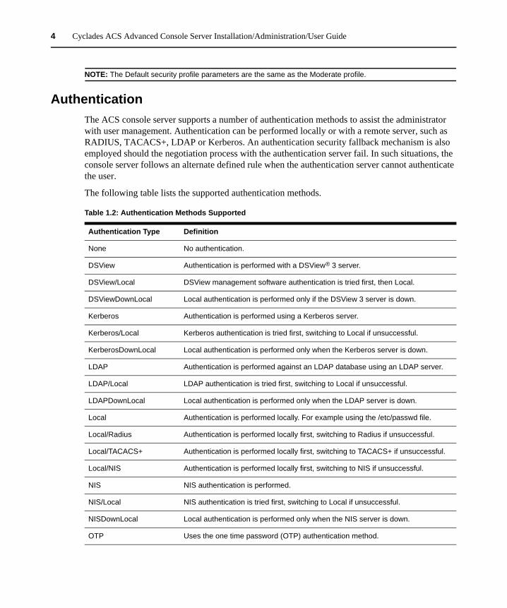
The following table lists the supported authentication methods.
Table 1.2: Authentication Methods Supported
Authentication Type Definition
None No authentication.
DSView Authentication is performed with a DSView® 3 server.
DSView/Local DSView management software authentication is tried first, then Local.
DSViewDownLocal Local authentication is performed only if the DSView 3 server is down.
Kerberos Authentication is performed using a Kerberos server.
Kerberos/Local Kerberos authentication is tried first, switching to Local if unsuccessful.
KerberosDownLocal Local authentication is performed only when the Kerberos server is down.
LDAP Authentication is performed against an LDAP database using an LDAP server.
LDAP/Local LDAP authentication is tried first, switching to Local if unsuccessful.
LDAPDownLocal Local authentication is performed only when the LDAP server is down.
Local Authentication is performed locally. For example using the /etc/passwd file.
Local/Radius Authentication is performed locally first, switching to Radius if unsuccessful.
Local/TACACS+ Authentication is performed locally first, switching to TACACS+ if unsuccessful.
Local/NIS Authentication is performed locally first, switching to NIS if unsuccessful.
NIS NIS authentication is performed.
NIS/Local NIS authentication is tried first, switching to Local if unsuccessful.
NISDownLocal Local authentication is performed only when the NIS server is down.
OTP Uses the one time password (OTP) authentication method.
Chapter 1: Introduction 5
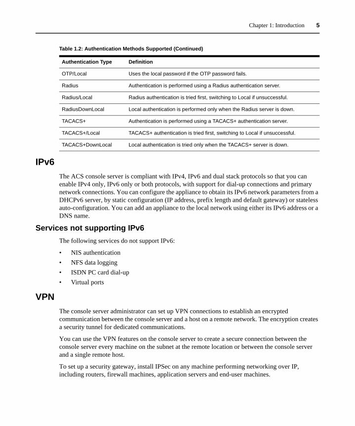
IPv6The ACS console server is compliant with IPv4, IPv6 and dual stack protocols so that you can enable IPv4 only, IPv6 only or both protocols, with support for dial-up connections and primary network connections. You can configure the appliance to obtain its IPv6 network parameters from a DHCPv6 server, by static configuration (IP address, prefix length and default gateway) or stateless auto-configuration. You can add an appliance to the local network using either its IPv6 address or a DNS name.
Services not supporting IPv6The following services do not support IPv6:
• NIS authentication• NFS data logging• ISDN PC card dial-up• Virtual ports
VPNThe console server administrator can set up VPN connections to establish an encrypted communication between the console server and a host on a remote network. The encryption creates a security tunnel for dedicated communications.
You can use the VPN features on the console server to create a secure connection between the console server every machine on the subnet at the remote location or between the console server and a single remote host.
To set up a security gateway, install IPSec on any machine performing networking over IP, including routers, firewall machines, application servers and end-user machines.
OTP/Local Uses the local password if the OTP password fails.
Radius Authentication is performed using a Radius authentication server.
Radius/Local Radius authentication is tried first, switching to Local if unsuccessful.
RadiusDownLocal Local authentication is performed only when the Radius server is down.
TACACS+ Authentication is performed using a TACACS+ authentication server.
TACACS+/Local TACACS+ authentication is tried first, switching to Local if unsuccessful.
TACACS+DownLocal Local authentication is tried only when the TACACS+ server is down.
Table 1.2: Authentication Methods Supported (Continued)
Authentication Type Definition
6 Cyclades ACS Advanced Console Server Installation/Administration/User Guide
The ESP and AH authentication protocols are supported. RSA Public Keys and Shared Secret are supported.
For detailed information and procedures to configure a VPN connection, see VPN Connections on page 89.
Packet FilteringThe administrator can configure the device to filter packets like a firewall. IP filtering is controlled by chains and rules.
Structure of IP filteringThe Firewall Configuration form in the Web Manager is structured on two levels:
• The view table of the Firewall Configuration form containing a list of chains. • The chains which contain the rules controlling filtering.
Chain
A chain is a named profile that includes one or more rules defining either a set of characteristics to look for in a packet or what to do with any packet having all the defined characteristics.
The console server filter table contains a number of built-in chains, each referenced according to the packet type they handle. As defined in the rules for the default chains, all input and output packets and packets being forwarded are accepted.
Rule
Each chain can have one or more rules that define either the packet characteristics being filtered or what to do when the packet matches the rule.
Each filtered packet characteristic is compared against the rules. All defined characteristics must match. If no rules are found then the default action for that chain is applied.
Administrators can:
• Add a new chain and specify rules for that chain• Add new rules to existing chains• Edit a built-in chain or delete the built-in chain rules
Chapter 1: Introduction 7
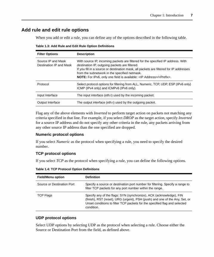
Add rule and edit rule optionsWhen you add or edit a rule, you can define any of the options described in the following table.
Flag any of the above elements with Inverted to perform target action on packets not matching any criteria specified in that line. For example, if you select DROP as the target action, specify Inverted for a source IP address and do not specify any other criteria in the rule, any packets arriving from any other source IP address than the one specified are dropped.
Numeric protocol options
If you select Numeric as the protocol when specifying a rule, you need to specify the desired number.
TCP protocol options
If you select TCP as the protocol when specifying a rule, you can define the following options.
UDP protocol options
Select UDP options by selecting UDP as the protocol when selecting a rule. Choose either the Source or Destination Port from the field, as defined above.
Table 1.3: Add Rule and Edit Rule Option Definitions
Filter Options Description
Source IP and Mask Destination IP and Mask
With source IP, incoming packets are filtered for the specified IP address. With destination IP, outgoing packets are filtered. If you fill in a source or destination mask, all packets are filtered for IP addresses from the subnetwork in the specified netmask. NOTE: For IPv6, only one field is available: <IP Address>/<Prefix>.
Protocol Select protocol options for filtering from ALL, Numeric, TCP, UDP, ESP (IPv6 only) ICMP (IPv4 only) and ICMPv6 (IPv6 only).
Input Interface The input interface (ethN) used by the incoming packet.
Output Interface The output interface (ethN) used by the outgoing packet.
Table 1.4: TCP Protocol Option Definitions
Field/Menu option Definition
Source or Destination Port Specify a source or destination port number for filtering. Specify a range to filter TCP packets for any port number within the range.
TCP Flags Specify any of the flags: SYN (synchronize), ACK (acknowledge), FIN (finish), RST (reset), URG (urgent), PSH (push) and one of the Any, Set, or Unset conditions to filter TCP packets for the specified flag and selected condition.
8 Cyclades ACS Advanced Console Server Installation/Administration/User Guide
ICMP protocol options
When you select ICMP as a protocol when specifying a rule, you can select the ICMP options available on the display.
Target actions
The Target is the action to be performed on an IP packet that matches all the criteria specified in a rule.
NOTE: If the LOG and REJECT targets are selected, additional options are available.
For detailed information on LOG target options, see LOG target on page 102.
For detailed information on REJECT target options, see REJECT target on page 103.
SNMPThe administrator can activate the Simple Network Management Protocol (SNMP) agent that resides on the console server so that the SNMP agent sends notifications about significant events or traps to an SNMP management application. The console server SNMP agent supports SNMP v1/v2 and v3.
See To configure SNMP: on page 96 for more information.
Notifications, Alarms and Data BufferingThe administrator can set up logging, notifications and alarms to alert administrators of problems. System generated messages on the console server and the connected servers or devices can be sent to syslog servers for handling. The administrator can also configure data buffering to store data from communication on serial ports for monitoring.
Data from communication with serial-connected consoles can be stored locally in the console server’s flash memory or remotely either on an NFS server or a syslog server.
Syslog serversMessages about the console server and connected servers or devices can be sent to central logging servers, called syslog servers. Console data from devices connected to serial ports can be stored in data buffer files on syslog servers. By default, logging and data buffering are not done.
Prerequisites for logging to syslog servers
Before configuring syslogging, ensure that syslog server is pre-configured with a public IP address and is accessible from the console server. The system administrator must obtain both the IP address of the syslog server from the syslog server’s administrator and the facility number for messages from the console server. Facility numbers are used on the syslog server for handling messages generated by multiple devices.
Chapter 1: Introduction 9
Facility numbers for syslog messages
Each syslog server has seven local facility numbers available for its administrator to assign to different devices or groups of devices, at different locations. The available facility numbers are Local0 through Local7.
Example of using facility numbers
The syslog system administrator sets up a server called syslogger to handle log messages from two console servers. One console server is located in São Paulo, Brazil and the other in Fremont, California. The syslog server’s administrator wishes to aggregate messages from the São Paulo console server into the local1 facility and to aggregate messages from Fremont console server into the local2 facility.
On syslogger the system administrator has configured the system logging utility to write messages from the local1 facility to the /var/log/saopaulo-config file and the messages from the local2 facility to the /var/log/fremont-config file. If you were in Fremont and identifying the syslog server using the Web Manager, according to this example, you would select the facility number local2 from the Facility Number pull-down menu on the Syslog form.
Managing Users of Connected DevicesThis section provides a list of tasks that a Cyclades ACS advanced console server administrator can perform to enable access to connected devices.
Configuring access to connected devicesDuring hardware installation of the console server, the installer connects the servers, devices and any IPDUs to the serial ports. During software configuration, the console server administrator performs the common tasks listed in the following table.
ACS Console Server and Power ManagementAuthorized users can turn on, turn off and reboot devices that are plugged into one of the following types of power devices, which can be optionally connected to any of the serial ports:
• Cyclades PM Intelligent Power Distribution Units (IPDUs) - With Cyclades PM IPDUs, up to 128 IPDU outlets can be daisy-chained from a single serial port
• Avocent SPC power control devices
Table 1.5: Common Administrator Tasks for Configuring Software
Task Where Documented
To Configure a Serial Port Connection Protocol for a Console Connection Page 133
To Configure User Access to Serial Ports Page 138
10 Cyclades ACS Advanced Console Server Installation/Administration/User Guide
• Server Technology Sentry™ family of Switched Cabinet Power Distribution Units (CDUs) and switched CDU Expansion Module (CW/CX) power devices
• Server Technology Sentry Power Tower XL™ (PTXL) and Power Tower Expansion Module (PTXM) power devices
NOTE: The term IPDU is used to refer to any of these types of power devices.
The ACS console server automatically recognizes and supports a Cyclades PM IPDU or Avocent SPC device when the serial port to which the power device is connected has been configured for power management.
Additional requirements for Server Technology IPDUs
For supported Server Technology IPDUs the following additional requirements apply:
• The ACS console server must be managed by a DSView 3 server (DSView 3 software version 3.4.1 or above).
• The needed power device license must be present, and the power device must be added to the DSView 3 software.
The license is automatically downloaded from the DSView 3 server onto the console server. Configuration and management can then be performed either through the DSView software or through the Web Manager.
Conventions used to identify outlets
Several formats (such as outlet names, outlet groups, IPDU IDs and port names) can be used to identify outlets during configuration, as described below:
• An administrator can configure optional names for each outlet to replace the default names assigned by the system. Outlet names must begin with a letter. Valid characters are letters, numbers, dash (-) and underscore (_). When an outlet name is configured, the name can be used in other power management configurations.
NOTE: Outlet names can be configured in two places in the Web Manager. Ensure that names are consistent.
• An administrator can configure outlet groups. Once defined, outlet groups are specified with the dollar sign ($) prefix followed by the outlet group name: $outlet_groupname. For example, $Cyclades_IPDU specifies an outlets group called Cyclades_IPDU.
• An administrator can specify outlets in any of the following ways:• With a name that was configured for the outlet• With an outlet group name preceded by the $ suffix• With the IPDU ID assigned to the IPDU• With the port number to which the IPDU is connected
Chapter 1: Introduction 11
The IPDU and port number are always followed by one or more outlet numbers in brackets: [outlets]. Commas between outlet numbers indicate multiple outlets. Hyphens indicate a range. For example, [1,5-8] specifies outlets 1, 5, 6, 7 and 8.
• IPDU ID - An IPDU ID is automatically assigned to each IPDU when the port to which it is connected is configured for power management. An administrator can optionally assign a name to each IPDU. Both automatically assigned and administrator-assigned names are referred to as IPDU IDs.• Specify outlets with the IPDU ID in the following format: IPDU_ID[outlets]. For
example, ilA[4,5] specifies outlets 4 and 5 on an IPDU whose ID is ilA.• When devices are plugged into more than one IPDU, you can separate multiple IPDU
entries with commas in the form IPDU_ID[outlets],IPDU_ID[outlets]. For example, i1A[1,5],i1B[2] specifies two outlets on IPDU i1A and one outlet on a daisy-chained IPDU whose IPDU ID is ilB.
• Port number - To specify outlets by the port number to which the IPDU is connected, use the suffix !ttyS followed by the port number followed by [outlets]. For example, !ttyS2[16] indicates outlet 16 on an IPDU that is connected to serial port 2.
You can specify outlets in a chain of IPDUs with the port ID two different ways:
• By the outlet sequence. For example, in !ttyS3[2,16], outlet number 2 is the second outlet on the first IPDU in a chain that is connected to port 3. If the first IPDU has 10 outlets, outlet number 16 would be the sixth outlet on the second IPDU.
• By IPDU sequence, identified with alphabetic characters. The first IPDU is A and the second is B and so forth. Precede the character with a hyphen. For example, !ttyS3-B[6] would also refer to the sixth outlet on the second IPDU in the chain connected to port 3.
Configuring power managementAdministrators commonly perform power management through the Web Manager to assign power management permissions to users, configure IPMI devices and configure ports for power management.
Configuring ports for power management by authorized users
Administrators of connected devices who have power management permissions can do power management while connected by using a hotkey that brings up a power management screen.
For IPMI power management, the default hotkey is Ctrl+Shift+I. For IPDU power management, the default hotkey is Ctrl+p.
Options for managing power Authorized users can perform power management through the console server by using forms in the web manager, from a power management screen while logged into a device or from the command line while logged into the console server.
12 Cyclades ACS Advanced Console Server Installation/Administration/User Guide
An authorized user with administrative privileges can perform IPDU and IPMI power management. A regular user with permissions to the connected devices can perform IPDU power management.
Power management through the Web Manager
Users with power management permissions can perform power management through the Web Manager. The Web Manager menu includes two power management options, both discussed in Chapter 6.
Power management from the console server command line interface (CLI)
ACS console server administrators can use the ipmitool command to manage power on IPMI devices while logged into the console server with administrative rights. The ipmitool command is documented in the Cyclades ACS Command Reference Guide.
Hostname DiscoveryAn administrator can configure hostname discovery on the console server. When hostname discovery is enabled for a serial port, the console server attempts to discover the hostname of the server connected to the port. If the hostname of a server is successfully discovered, the hostname of the device connected to it is shown as the serial port alias.
If the server is later moved to another port, and the new port is also configured for hostname discovery, the hostname for the server is again discovered at the new serial port.
NOTE: If the console server is being managed through DSView 3 software, hostname discovery can be configured through the DSView 3 software.
An administrator can also configure site-specific probe and answer strings. These strings are used to probe the target device that is connected to the selected serial port and extract the hostname from the answer that is received in response to the probe string. The result of each probe string is matched against all answer strings. If no match is found, the next probe string is sent until there are no more probe strings or a match occurs. The default strings have a broad range and work in most cases.
NOTE: Probe string configuration requires knowledge of C-style escape sequences. Answer strings require knowledge of POSIX extended regular expressions. Hostnames longer than 31 characters are truncated when the hostname is assigned to the serial port alias.
13
CHAPTER
2 Installation
Important Pre-installation RequirementsBefore installing and configuring the console server, ensure that you have the following:
• Root Access on your local UNIX machine to use the serial ports.• An appropriate terminal application for your operating system.• IP address, DNS, Network Mask and Gateway addresses of your server or terminal, the
console server and the machine to which the console server is connected. • A web browser that supports the console server Web Manager, such as Netscape, Internet
Explorer, Firefox or Mozilla.• Java 2 Runtime Environment (JRE) version 1.4.2 or later. If a more recent version is available,
go to http://java.com to locate and download the latest version of J2RE.
Basic Installation ProceduresMounting the console server
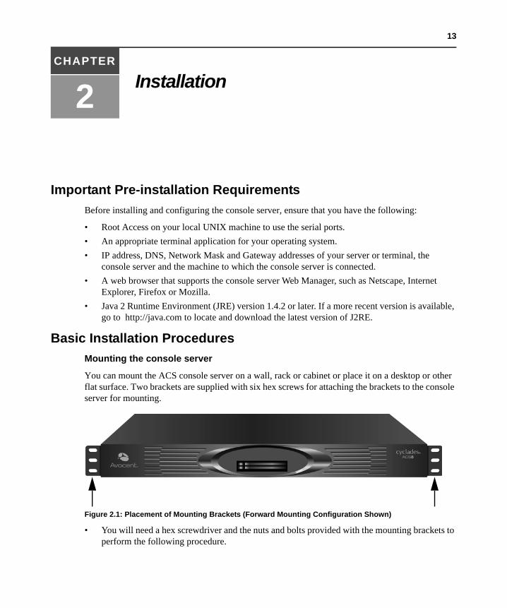
You can mount the ACS console server on a wall, rack or cabinet or place it on a desktop or other flat surface. Two brackets are supplied with six hex screws for attaching the brackets to the console server for mounting.
Figure 2.1: Placement of Mounting Brackets (Forward Mounting Configuration Shown)
• You will need a hex screwdriver and the nuts and bolts provided with the mounting brackets to perform the following procedure.
14 Cyclades ACS Advanced Console Server Installation/Administration/User Guide
To rack mount the console server:
1. Install the brackets on to the front or back edges of the ACS console server using a screw driver and the screws provided with the mounting kit.
2. Mount the console server unit in a secure position.
Making an Ethernet connectionConnect a CAT5 patch cable from the console server port labeled 10/100Base-T to an Ethernet hub or switch.
To connect devices to serial ports:
Using patch cables with RJ-45 connectors and DB-9 console adaptors assemble crossover cables to connect the console server serial ports to the device’s console port.
NOTE: For ACS 16 NEBS and ACS 32 NEBS models with single or dual DC power supplies, you must use shielded cables when connecting devices to the serial ports. Shielded cables are required to comply with NEBS Level 3 certification on these models. In addition, to meet RoHS requirements, a ferrite bead with equal or better impedance than TDK ZCAT2436-1330 must be installed on the Ethernet cable near the console server’s Ethernet port.
Making a direct connection to configure the network parameters.On your Windows workstation, ensure that a terminal emulation program is installed. On servers running a UNIX-based operating system such as Solaris or Linux, make sure that a compatible terminal emulator such as Kermit or Minicom is installed.
To connect to the console port:
You can use a CAT5 straight-through cable with RJ-45 connectors and the appropriate adaptor provided in the product box to assemble a console cable. All adaptors have an RJ-45 connector on one end and either a DB25 or DB9 male or female connector on the other end.
1. Connect the RJ-45 end of the cable to the port labeled Console on the console server.2. Connect the adaptor end of the cable to the console port of your server or device.3. Open your terminal emulation program, start a connection session, select an available COM
port and enter the following console parameters.• Bits per second: 9600 bps• Data bits: 8• Parity: None• Stop bit: 1• Flow control: None
Chapter 2: Installation 15
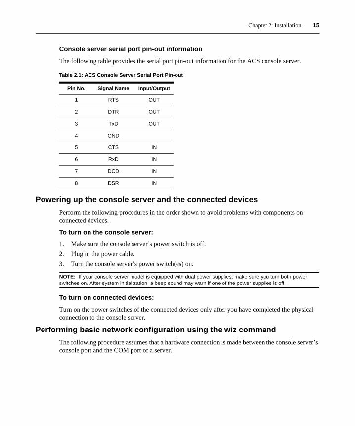
Console server serial port pin-out information
The following table provides the serial port pin-out information for the ACS console server.
Powering up the console server and the connected devicesPerform the following procedures in the order shown to avoid problems with components on connected devices.
To turn on the console server:
1. Make sure the console server’s power switch is off. 2. Plug in the power cable. 3. Turn the console server’s power switch(es) on.
NOTE: If your console server model is equipped with dual power supplies, make sure you turn both power switches on. After system initialization, a beep sound may warn if one of the power supplies is off.
To turn on connected devices:
Turn on the power switches of the connected devices only after you have completed the physical connection to the console server.
Performing basic network configuration using the wiz commandThe following procedure assumes that a hardware connection is made between the console server’s console port and the COM port of a server.
Table 2.1: ACS Console Server Serial Port Pin-out
Pin No. Signal Name Input/Output
1 RTS OUT
2 DTR OUT
3 TxD OUT
4 GND
5 CTS IN
6 RxD IN
7 DCD IN
8 DSR IN
16 Cyclades ACS Advanced Console Server Installation/Administration/User Guide
To log into the console server through the console:
From your terminal emulation application, log into the console port as root.
console server login: root Password: tslinux
WARNING:For security reasons, it is recommended that you change the default password tslinux as soon as possible. To change the default password, enter the passwd command at the prompt and enter a new password when prompted.
NOTE: The Security Advisory appears the first time console server is accessed or after a reset to factory default parameters. If you are upgrading the firmware on the console server, the previously configured security parameters are retained in the Flash memory.
To use the wiz command to configure network parameters:
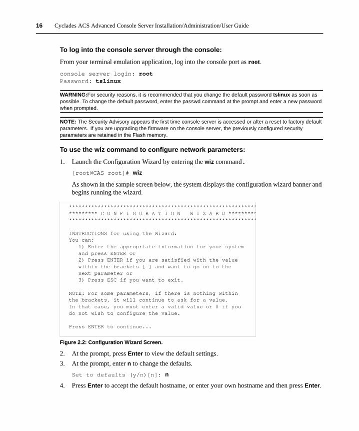
1. Launch the Configuration Wizard by entering the wiz command.[root@CAS root]# wiz
As shown in the sample screen below, the system displays the configuration wizard banner and begins running the wizard.
Figure 2.2: Configuration Wizard Screen.
2. At the prompt, press Enter to view the default settings.3. At the prompt, enter n to change the defaults.
Set to defaults (y/n)[n]: n
4. Press Enter to accept the default hostname, or enter your own hostname and then press Enter.
******************************************************************** C O N F I G U R A T I O N W I Z A R D ********************************************************************
INSTRUCTIONS for using the Wizard:You can: 1) Enter the appropriate information for your system and press ENTER or 2) Press ENTER if you are satisfied with the value within the brackets [ ] and want to go on to the next parameter or 3) Press ESC if you want to exit.
NOTE: For some parameters, if there is nothing withinthe brackets, it will continue to ask for a value.In that case, you must enter a valid value or # if youdo not wish to configure the value.
Press ENTER to continue...
Chapter 2: Installation 17
Hostname [CAS]: <hostname server name>
5. The IP version Configuration form is displayed. Select the IP version you wish to run and press Enter. Choices are IPv4 enabled (0), IPv6 enabled (1) or Dual Stack (2).
NOTE: Depending on which IP configuration you choose, the Wizard will direct you to the appropriate form.
To configure for IPv4 protocol:
1. If you have typed 0 or 2 for IP version configuration, the IPv4 Configuration form will appear and give you the choice to use DHCP to assign an IP address for your system. Default is Y.
2. Press Enter to keep DHCP enabled or type n to specify a static IP address for console server. By default, the console server uses the IP address provided by the DHCP server. If your network does not use DHCP, the console server will default to 192.168.160.10.
Do you want to use DHCP to automatically assign an IP for your system? (y/n)[y] :
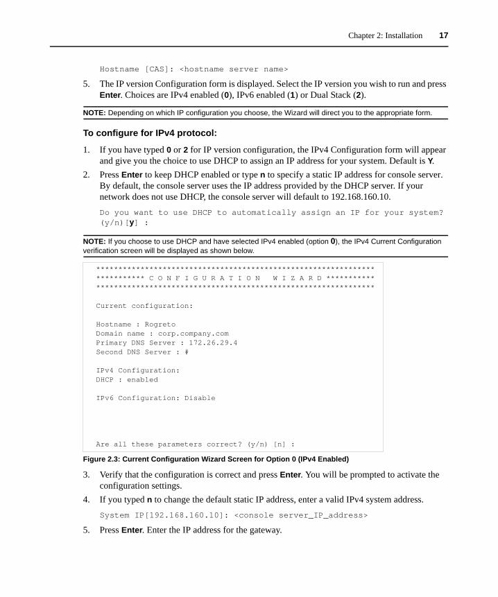
NOTE: If you choose to use DHCP and have selected IPv4 enabled (option 0), the IPv4 Current Configuration verification screen will be displayed as shown below.
Figure 2.3: Current Configuration Wizard Screen for Option 0 (IPv4 Enabled)
3. Verify that the configuration is correct and press Enter. You will be prompted to activate the configuration settings.
4. If you typed n to change the default static IP address, enter a valid IPv4 system address.
System IP[192.168.160.10]: <console server_IP_address>
5. Press Enter. Enter the IP address for the gateway.
*************************************************************** *********** C O N F I G U R A T I O N W I Z A R D **************************************************************************
Current configuration:
Hostname : RogretoDomain name : corp.company.comPrimary DNS Server : 172.26.29.4Second DNS Server : #
IPv4 Configuration:DHCP : enabled
IPv6 Configuration: Disable
Are all these parameters correct? (y/n) [n] :
18 Cyclades ACS Advanced Console Server Installation/Administration/User Guide
Gateway IP[eth0] : <gateway_IP_address>
6. Press Enter. Enter the netmask for the subnetwork.Network Mask[#] : <netmask>
7. Press Enter.
NOTE: If you have selected IPv4 enabled and have set the static IP, gateway and netmask addresses, the IPv4 Current Configuration verification screen will be displayed. Check all parameters and press Enter. You will be prompted to activate the configuration settings.
To configure for IPv6 protocol:
1. If you entered option 1 or 2 for IP version configuration, the IPv6 Configuration Method form will be displayed.
2. Choices for IPv6 configuration are Stateless Only (0), Static (1) or DHCP (2). The default is Stateless Only. Type the number corresponding to your choice and press Enter. The choice you enter selects the method used to assign the IPv6 system address.• Stateless Only: The router will multicast the IPv6 prefix along with the console server’s
MAC address, then listen for the other devices on the local network to allow the router to assign the IPv6 address.
• Static: You must manually assign a unique IPv6 address for the console server.• DHCP: The router will request the IPv6 address from the DHCPv6 server.
3. The DHCPv6 options form is displayed. Choices are None (0), DNS (1), Domain (2) and DNS and Domain (3). Type the number corresponding to your choice and press Enter.• From None (0): Enter your domain name.• From Domain (1): Enter your domain name.• From DNS (2): Follow the on-screen instructions.• From DNS (3): The Current Configuration screen is displayed.
4. If None (0) or Domain (1), enter your domain name.Domain name[corp.avocent.com] :
5. Enter the IPv4 or IPv6 address for the Primary DNS (domain name) server.Primary DNS Server[172.26.29.4] : <DNS_server_IPv4_or_IPv6_address>
6. Press Enter. The Current Configurations screen appears. If correct, enter y after the prompts shown in the following screen example. Are all these parameters correct? (y/n)[n]: y
Do you want to activate your configurations now? (y/n)[y]: y
Do you want to save your configuration to Flash? (y/n)[n]: y
7. To confirm the configuration, enter the ifconfig command.
Chapter 2: Installation 19
8. After the initial configuration, proceed to the Web Manager to select a security profile as described in the following section.
NOTE: To use the Web Manager, obtain your ACS console server’s IP address. The console server may be set up with a static IP address at your site. By default, the console server uses the IP address provided by the DHCP server. If your network does not use DHCP, then the console server defaults to 192.168.160.10.
Selecting a security profile using the Web Manager
After the initial configuration, connect to the Web Manager by entering the IP address of the console server in a supported browser.
NOTE: Once you log in to the Web Manager, a Security Profile must be selected to further configure console server using the Web Manager. For this reason your browser redirects to Wizard - Step1: Security Profiles.
Selecting a Security Profile
Select a pre-defined Security Profile or define a Custom profile for specific services. The profiles are:
• Secured - Disables all protocols except sshv2, HTTPS and SSH to Serial Ports.• Moderate - Enables sshv1, sshv2, HTTP, HTTPS, Telnet, SSH and Raw connections to Serial
Ports, ICMP and HTTP redirection to HTTPS.• Open - Enables Telnet, sshv1, sshv2, HTTP, HTTPS, SNMP, RPC, ICMP, SSH and Raw
connections to Serial Ports.• Default - Sets the profile to the same configuration as Moderate profile.• Custom - Allows custom configuration of individual protocols and services.
For detailed information on Security Profiles, see Security Profiles on page 122.
The administrator can perform the following tasks using the Web Manager.
• Administer the console server and its connected devices.• Configure user and group permissions.• Access the serial ports and the connected devices.
Adding users and configuring ports using the Web Manager
NOTE: From the factory, the console server is configured with all serial ports disabled.
The administrator can add users, enable or disable the serial ports and select and assign specific users to individual ports. For more information on managing users and ports, see Security Menu and Forms on page 111 and Ports Menu and Forms on page 129.
20 Cyclades ACS Advanced Console Server Installation/Administration/User Guide
Other Methods of Accessing the Web ManagerYou can access the Web Manager using either DHCP or the default IP address.
NOTE: Accessing the Web Manager using either DHCP or the default IP address requires additional setup and configuration specific to your site’s network configuration.
To use a dynamic IP address to access the Web Manager:
This procedure assumes that DHCP is enabled and that you are able to obtain the dynamic IP address currently assigned to the console server.
1. Mount the console server.2. Connect servers and other devices to be managed through the console server.3. Turn on the console server and connected devices.4. Enter the console server’s IP address in the browser’s address field.5. Log in to the console server and finish configuring users and other settings using the
Web Manager.
To use the default IP address to access the Web Manager:
The default IP address for the console server is 192.168.160.10. This procedure assumes that you are able to temporarily change the IP address of a server located on the same subnet as the ACS console server.
1. On a server that resides on the same subnet as the console server, change the network portion of the IP address of that server to 192.168.160. For the host portion of the IP address, you can use any number except 10, 0 or 255.
2. Open a browser on the server with the changed address. Enter the console server’s default IP address, http://192.168.160.10, to bring up the Web Manager and log in.
Installing PC CardsThe front panel of the console server has two PC card slots. You can insert and configure one card in each of the slots.
To see a list of supported PC cards go to http://www.avocent.com/ and follow the product links for ACS.
To install a PC card:
1. Insert the PC card into slot 1 or slot 2.2. Use the Web Manager to configure the PC card.
NOTE: A hard disk PC card is automatically mounted and configured once it is inserted.
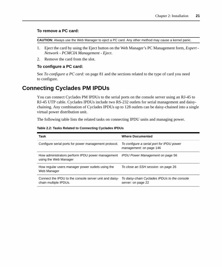
Chapter 2: Installation 21
To remove a PC card:
CAUTION: Always use the Web Manager to eject a PC card. Any other method may cause a kernel panic.
1. Eject the card by using the Eject button on the Web Manager’s PC Management form, Expert - Network - PCMCIA Management - Eject.
2. Remove the card from the slot.
To configure a PC card:
See To configure a PC card: on page 81 and the sections related to the type of card you need to configure.
Connecting Cyclades PM IPDUsYou can connect Cyclades PM IPDUs to the serial ports on the console server using an RJ-45 to RJ-45 UTP cable. Cyclades IPDUs include two RS-232 outlets for serial management and daisy-chaining. Any combination of Cyclades IPDUs up to 128 outlets can be daisy-chained into a single virtual power distribution unit.
The following table lists the related tasks on connecting IPDU units and managing power.
Table 2.2: Tasks Related to Connecting Cyclades IPDUs
Task Where Documented
Configure serial ports for power management protocol. To configure a serial port for IPDU power management: on page 146
How administrators perform IPDU power management using the Web Manager
IPDU Power Management on page 56
How regular users manager power outlets using the Web Manager
To close an SSH session: on page 26
Connect the IPDU to the console server unit and daisy-chain multiple IPDUs.
To daisy-chain Cyclades IPDUs to the console server: on page 22
22 Cyclades ACS Advanced Console Server Installation/Administration/User Guide
Connecting third-party IPDUs
IPDUs from SPC and ServerTech can be connected to and managed by the ACS console server. Special cabling and an adaptor is required for this purpose. These cables and adaptors are available from Avocent,or you can build your own cable as needed. See Console server serial port pin-out information on page 15 for this purpose.
NOTE: ServerTech IPDU installation, management and operation is license based through Avocent’s DSView®3 management software only.
To daisy-chain Cyclades IPDUs to the console server:
This procedure assumes that you have one Cyclades PM IPDU connected to a serial port on the console server.
NOTE: Daisy-chaining is not possible with SPC IPDUs. ServerTechIPDUs will allow only one level (Master and Slave) of daisy chaining.
1. Connect one end of a UTP cable with RJ-45 connectors to the OUT port of the Cyclades IPDU connected to the serial port on the console server.
2. Connect the other end of the cable to the IN port of the next Cyclades IPDU.3. Repeat steps 1 and 2 until you have connected the desired number of Cyclades IPDUs. Only
one additional level is allowed with ServerTech IPDUs.
Contact Avocent Technical Support for more information on:
• installing SPC and ServerTech IPDUs• replacing an Avocent CCM console management appliance with a Cyclades ACS console
server• cabling requirements for using the ACS console server with SPC and ServerTech IPDUs
23
CHAPTER
3 Web Manager for Regular Users
Using the Web ManagerACS console server users perform most tasks through the Web Manager. The Web Manager runs in a browser and provides a real-time view of all equipment connected to the console server.
Authorized users can use the Web Manager to access devices connected to serial ports:
• If a device console is connected, the user can access the console of the target device. • If a terminal is connected, the user can connect from the terminal to the console server and
access other servers. • If a modem is connected, a user can dial in and access the console server and connected
devices.• If an IPDU is connected, a user can manage power for devices connected to the outlets of the
IPDU.
To log into the Web Manager:
1. Type the console server’s IP address in your browser’s address field.
NOTE: Refer to Chapter 2 for requirements to start the Web Manager.
2. Press Enter. The Web Manager Login form is displayed.3. Enter your username and password.
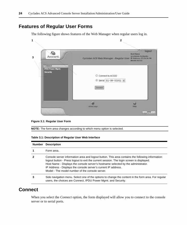
24 Cyclades ACS Advanced Console Server Installation/Administration/User Guide
Features of Regular User FormsThe following figure shows features of the Web Manager when regular users log in.
Figure 3.1: Regular User Form
NOTE: The form area changes according to which menu option is selected.
ConnectWhen you select the Connect option, the form displayed will allow you to connect to the console server or to serial ports.
Table 3.1: Description of Regular User Web Interface
Number Description
1 Form area.
2 Console server information area and logout button. This area contains the following information:logout button - Press logout to exit the current session. The login screen is displayed.Host Name - Displays the console server’s hostname selected by the administrator.IP Address - Displays the console server’s current IP address.Model - The model number of the console server.
3 Side navigation menu. Select one of the options to change the content in the form area. For regular users, the choices are Connect, IPDU Power Mgmt. and Security.
1
3
2
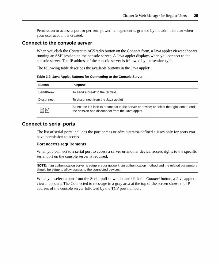
Chapter 3: Web Manager for Regular Users 25
Permission to access a port or perform power management is granted by the administrator when your user account is created.
Connect to the console serverWhen you click the Connect to ACS radio button on the Connect form, a Java applet viewer appears running an SSH session on the console server. A Java applet displays when you connect to the console server. The IP address of the console server is followed by the session type.
The following table describes the available buttons in the Java applet:
Connect to serial portsThe list of serial ports includes the port names or administrator-defined aliases only for ports you have permission to access.
Port access requirements
When you connect to a serial port to access a server or another device, access rights to the specific serial port on the console server is required.
NOTE: If an authentication server is setup in your network, an authentication method and the related parameters should be setup to allow access to the connected devices.
When you select a port from the Serial pull-down list and click the Connect button, a Java applet viewer appears. The Connected to message in a gray area at the top of the screen shows the IP address of the console server followed by the TCP port number.
Table 3.2: Java Applet Buttons for Connecting to the Console Server
Button Purpose
SendBreak To send a break to the terminal
Disconnect To disconnect from the Java applet
Select the left icon to reconnect to the server or device; or select the right icon to end the session and disconnect from the Java applet.
26 Cyclades ACS Advanced Console Server Installation/Administration/User Guide
Connection protocols for serial portsYou can access a server or a device connected to a serial port by using the connection protocol specified for the port. The following table shows the protocols available for the serial ports.
TCP port numbers for serial ports
The TCP port numbers by default start at 7001 for serial port 1 and increment up to the number of serial ports on your console server. The console server administrator may change the default port numbers if needed.
To use Telnet to connect to a device through a serial port:
For this procedure you need the hostname of the console server or its IP address and the TCP port number for the serial port to which the device is connected.
• To use Telnet in a shell, enter the following command:telnet hostname | IP_address TCP_port_number
To close a Telnet session:
Enter the Telnet hotkey defined for the client. The default is Ctrl ] and q to quit.
To use SSH to connect to a device through a serial port:
For this procedure, you need the username configured to access the serial port, the TCP port number and the hostname of the console server or its IP address.
• To use SSH in a shell, enter the following command:SSH - # ssh -l username:TCP_port_number console_server_IP_address|or the hostname
To close an SSH session:
Enter the hotkey defined for the SSH client followed by a period. The default is ~.
NOTE: Make sure you enter the escape character followed by a period at the beginning of a line to close the SSH session.
Table 3.3: Available Serial Port Protocols
Connection Type Protocol
Console Access Server (CAS) Telnet, ssh, Telnet&ssh, Raw
Terminal Server (TS) Telnet, sshv1, sshv2, Local Terminal, Raw Socket
Dial-up PPP-No Auth., PPP, SLIP, CSLIP
Other Power Management, Bi-directional Telnet
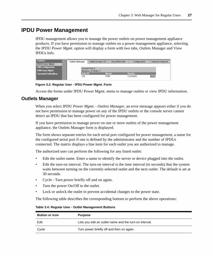
Chapter 3: Web Manager for Regular Users 27
IPDU Power ManagementIPDU management allows you to manage the power outlets on power management appliance products. If you have permission to manage outlets on a power management appliance, selecting the IPDU Power Mgmt. option will display a form with two tabs, Outlets Manager and View IPDUs Info.
Figure 3.2: Regular User - IPDU Power Mgmt. Form
Access the forms under IPDU Power Mgmt. menu to manage outlets or view IPDU information.
Outlets ManagerWhen you select IPDU Power Mgmt. - Outlets Manager, an error message appears either if you do not have permission to manage power on any of the IPDU outlets or the console server cannot detect an IPDU that has been configured for power management.
If you have permission to manage power on one or more outlets of the power management appliance, the Outlets Manager form is displayed.
The form shows separate entries for each serial port configured for power management, a name for the configured serial port if one is defined by the administrator and the number of IPDUs connected. The matrix displays a line item for each outlet you are authorized to manage.
The authorized user can perform the following for any listed outlet:
• Edit the outlet name. Enter a name to identify the server or device plugged into the outlet. • Edit the turn-on interval. The turn-on interval is the time interval (in seconds) that the system
waits between turning on the currently-selected outlet and the next outlet. The default is set at 30 seconds.
• Cycle - Turn power briefly off and on again.• Turn the power On/Off to the outlet.• Lock or unlock the outlet to prevent accidental changes to the power state.
The following table describes the corresponding buttons to perform the above operations:
Table 3.4: Regular User - Outlet Management Buttons
Button or icon Purpose
Edit Lets you edit an outlet name and the turn-on interval.
Cycle Turn power briefly off and then on again.
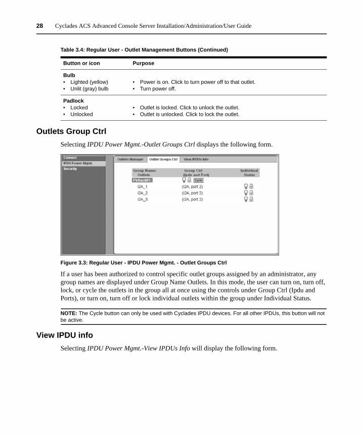
28 Cyclades ACS Advanced Console Server Installation/Administration/User Guide
Outlets Group CtrlSelecting IPDU Power Mgmt.-Outlet Groups Ctrl displays the following form.
Figure 3.3: Regular User - IPDU Power Mgmt. - Outlet Groups Ctrl
If a user has been authorized to control specific outlet groups assigned by an administrator, any group names are displayed under Group Name Outlets. In this mode, the user can turn on, turn off, lock, or cycle the outlets in the group all at once using the controls under Group Ctrl (Ipdu and Ports), or turn on, turn off or lock individual outlets within the group under Individual Status.
NOTE: The Cycle button can only be used with Cyclades IPDU devices. For all other IPDUs, this button will not be active.
View IPDU infoSelecting IPDU Power Mgmt.-View IPDUs Info will display the following form.
Bulb• Lighted (yellow)• Unlit (gray) bulb
• Power is on. Click to turn power off to that outlet.• Turn power off.
Padlock• Locked• Unlocked
• Outlet is locked. Click to unlock the outlet.• Outlet is unlocked. Click to lock the outlet.
Table 3.4: Regular User - Outlet Management Buttons (Continued)
Button or icon Purpose
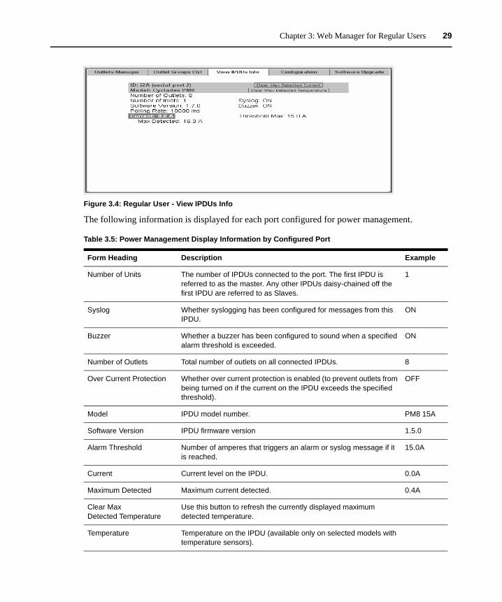
Chapter 3: Web Manager for Regular Users 29
Figure 3.4: Regular User - View IPDUs Info
The following information is displayed for each port configured for power management.
Table 3.5: Power Management Display Information by Configured Port
Form Heading Description Example
Number of Units The number of IPDUs connected to the port. The first IPDU is referred to as the master. Any other IPDUs daisy-chained off the first IPDU are referred to as Slaves.
1
Syslog Whether syslogging has been configured for messages from this IPDU.
ON
Buzzer Whether a buzzer has been configured to sound when a specified alarm threshold is exceeded.
ON
Number of Outlets Total number of outlets on all connected IPDUs. 8
Over Current Protection Whether over current protection is enabled (to prevent outlets from being turned on if the current on the IPDU exceeds the specified threshold).
OFF
Model IPDU model number. PM8 15A
Software Version IPDU firmware version 1.5.0
Alarm Threshold Number of amperes that triggers an alarm or syslog message if it is reached.
15.0A
Current Current level on the IPDU. 0.0A
Maximum Detected Maximum current detected. 0.4A
Clear Max Detected Temperature
Use this button to refresh the currently displayed maximum detected temperature.
Temperature Temperature on the IPDU (available only on selected models with temperature sensors).
30 Cyclades ACS Advanced Console Server Installation/Administration/User Guide
SecurityUse the following procedure to set or change your password.
To change your password:
1. Select the Security option from the menu panel. The Security form appears.2. Enter your current password in the Current Password field.3. Enter the new password in the New Password and the Repeat New Password fields. 4. Click OK.5. Log out and log in using your new password to verify your password change.
Maximum Detected Maximum temperature detected (Available only on selected models with temperature sensors).
Clear Max Detected Current
Use this button to refresh the currently displayed maximum detected current.
Table 3.5: Power Management Display Information by Configured Port (Continued)
Form Heading Description Example
31
CHAPTER
4 Web Manager for Administrators
This chapter is for system administrators who use the Web Manager to configure the Cyclades ACS advanced console server and its users. For information on how to configure the console server using vi or Command Line Interface (CLI), please consult the Cyclades ACS Command Reference Guide.
The ACS console server’s Web Manager for administrators describes two modes of operation, Wizard and Expert.
This section provides an overview of the Web Manager forms. Subsequent sections describe the menus, forms and the configuration procedures of the Web Manager in Wizard and Expert modes. If you are a regular user, see Chapter 3.
Common Tasks for ACS Console Server AdministratorsThe following table shows some of the common tasks that are performed by an administrator and references to more information about performing the task.
Table 4.1: Administrator - Common Administrative Tasks
Task Where documented
Set up users and groups to access connected devices.
Users and Groups on page 111
Set up user authentication to access serial ports. Access on page 137
Configure serial ports for power management. To configure a power management protocol for an IPDU: on page 135
Assign users permissions to manage outlets on connected Cyclades PMs.
To configure an outlet group: on page 66
Set up local or remote data buffering and specify alarms for one or more serial ports.
To configure data buffering for serial ports: on page 141To choose a method for sending notifications for serial port data buffering events: on page 158
Set up logging of system messages to a syslog server.
To view and reset IPDU information: on page 62
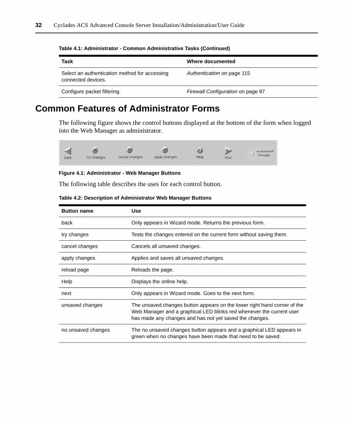
32 Cyclades ACS Advanced Console Server Installation/Administration/User Guide
Common Features of Administrator FormsThe following figure shows the control buttons displayed at the bottom of the form when logged into the Web Manager as administrator.
Figure 4.1: Administrator - Web Manager Buttons
The following table describes the uses for each control button.
Select an authentication method for accessing connected devices.
Authentication on page 115
Configure packet filtering. Firewall Configuration on page 97
Table 4.1: Administrator - Common Administrative Tasks (Continued)
Task Where documented
Table 4.2: Description of Administrator Web Manager Buttons
Button name Use
back Only appears in Wizard mode. Returns the previous form.
try changes Tests the changes entered on the current form without saving them.
cancel changes Cancels all unsaved changes.
apply changes Applies and saves all unsaved changes.
reload page Reloads the page.
Help Displays the online help.
next Only appears in Wizard mode. Goes to the next form.
unsaved changes The unsaved changes button appears on the lower right hand corner of the Web Manager and a graphical LED blinks red whenever the current user has made any changes and has not yet saved the changes.
no unsaved changes The no unsaved changes button appears and a graphical LED appears in green when no changes have been made that need to be saved.
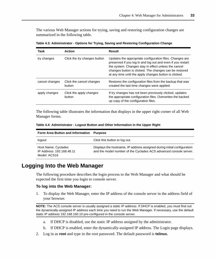
Chapter 4: Web Manager for Administrators 33
The various Web Manager actions for trying, saving and restoring configuration changes are summarized in the following table.
The following table illustrates the information that displays in the upper right corner of all Web Manager forms.
Logging Into the Web ManagerThe following procedure describes the login process to the Web Manager and what should be expected the first time you login to console server.
To log into the Web Manager:
1. To display the Web Manager, enter the IP address of the console server in the address field of your browser.
NOTE: The ACS console server is usually assigned a static IP address. If DHCP is enabled, you must find out the dynamically-assigned IP address each time you need to run the Web Manager. If necessary, use the default static IP address 192.168.160.10 pre-configured in the console server.
a. If DHCP is disabled, use the static IP address assigned by the administrator.b. If DHCP is enabled, enter the dynamically-assigned IP address. The Login page displays.
2. Log in as root and type in the root password. The default password is tslinux.
Table 4.3: Administrator - Options for Trying, Saving and Restoring Configuration Change
Task Action Result
try changes Click the try changes button Updates the appropriate configuration files. Changes are preserved if you log in and log out and even if you restart the system. Changes stay in effect unless the cancel changes button is clicked. The changes can be restored at any time until the apply changes button is clicked.
cancel changes Click the cancel changes button
Restores the configuration files from the backup that was created the last time changes were applied.
apply changes Click the apply changes button
If try changes has not been previously clicked, updates the appropriate configuration files. Overwrites the backed up copy of the configuration files.
Table 4.4: Administrator - Logout Button and Other Information in the Upper Right
Form Area Button and Information Purpose
logout Click this button to log out.
Host Name: CycladesIP Address: 192.168.48.11Model: ACS16
Displays the hostname, IP address assigned during initial configuration and the model number of the Cyclades ACS advanced console server.
34 Cyclades ACS Advanced Console Server Installation/Administration/User Guide
CAUTION: It is important to change the root password as soon as possible to avoid security breaches.
If another administrator is already logged in, a dialog box will prompt you to log off the other administrator before logging in.
3. Select Yes or No and then click Apply.
NOTE: Be sure to read the Security Advisory message that appears on the screen. Your pop-up blocker must be disabled for the Security Advisory to appear.
Overview of Administrative ModesThe console server Web Manager operates in one of two modes, Wizard or Expert.
NOTE: If you select Wizard, the mode button will read Expert. If you select Expert , the mode button will read Wizard.
Wizard modeThe Wizard mode is designed to simplify the setup and configuration process by guiding the administrator through six configuration steps.
When you log in to the console server as an administrator or as a user with administrative privileges, by default the system point to Expert Mode-Ports-Ports Status form.
The following is a typical form of the console server web interface in Wizard Mode. The user entry form varies depending on the selected menu item.
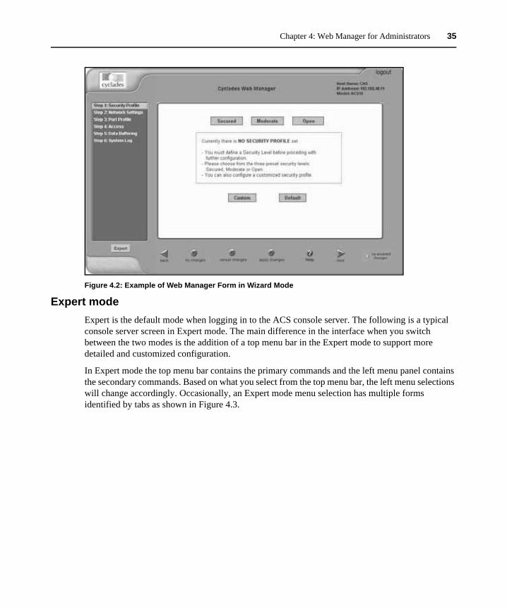
Chapter 4: Web Manager for Administrators 35
Figure 4.2: Example of Web Manager Form in Wizard Mode
Expert modeExpert is the default mode when logging in to the ACS console server. The following is a typical console server screen in Expert mode. The main difference in the interface when you switch between the two modes is the addition of a top menu bar in the Expert mode to support more detailed and customized configuration.
In Expert mode the top menu bar contains the primary commands and the left menu panel contains the secondary commands. Based on what you select from the top menu bar, the left menu selections will change accordingly. Occasionally, an Expert mode menu selection has multiple forms identified by tabs as shown in Figure 4.3.
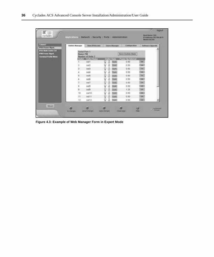
36 Cyclades ACS Advanced Console Server Installation/Administration/User Guide
Figure 4.3: Example of Web Manager Form in Expert Mode
37
CHAPTER
5 Configuring the ACS Console Server in Wizard Mode
Step 1: Security ProfileA security profile consists of a set of parameters that can be configured in order to have more control over the services active at any time.
Pre-defined security profiles
There are three pre-defined security profiles:
• Secure - Authentication to access Serial Ports is required and SSH root access is not allowed.
NOTE: SSH root access is enabled when the security profile is set to Moderate or Open. If a Secured security profile is selected, you must switch to a Custom security profile and enable the allow root access option.
• Moderate - The Moderate profile is the recommended security level. This profile enables sshv1, sshv2, HTTP, HTTPS, Telnet, SSH and Raw connections to the Serial Ports. In addition, ICMP and HTTP redirection to HTTPS are enabled. Authentication to access the serial ports is not required.
• Open - The Open profile enables all services such as Telnet, sshv1, sshv2, HTTP, HTTPS, SNMP, RPC, ICMP, SSH and Raw connections to the Serial Ports. Authentication to access serial ports is not required.
Default security profile
See the following tables for the list of enabled services when the Default security profile is used.
Custom security profile
The Custom security profile opens up a dialog box to allow custom configuration of individual protocols or services.
NOTE: By default, a number of protocols and services are enabled in the Custom profile; however, they are configurable to a user’s requirements.
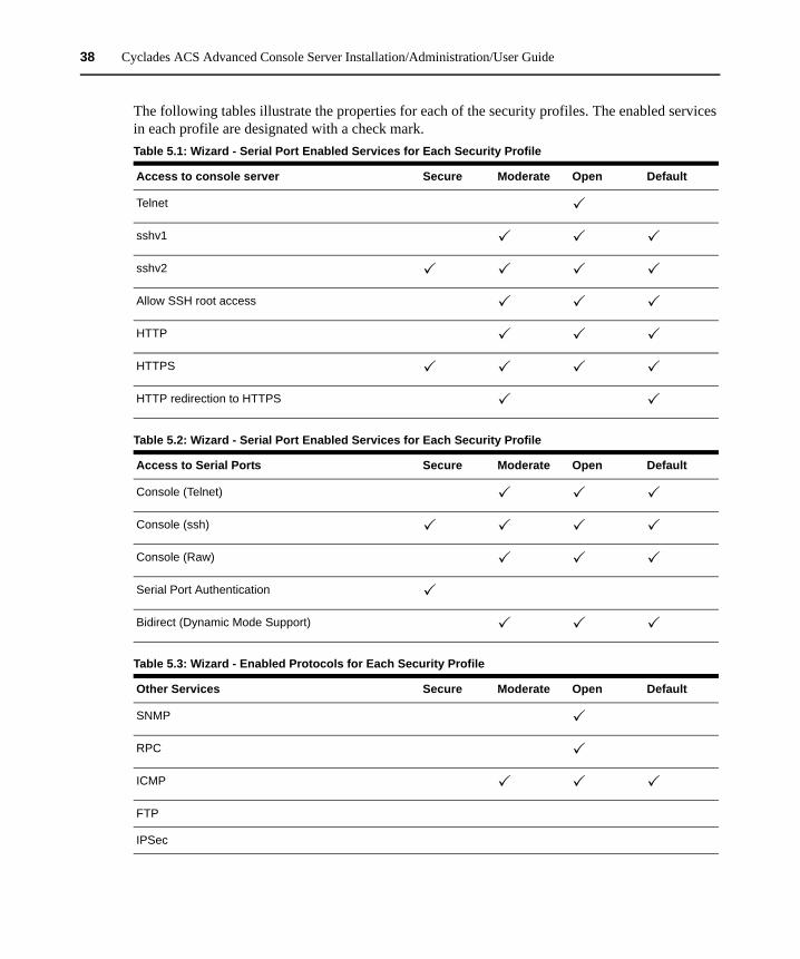
38 Cyclades ACS Advanced Console Server Installation/Administration/User Guide
The following tables illustrate the properties for each of the security profiles. The enabled services in each profile are designated with a check mark.Table 5.1: Wizard - Serial Port Enabled Services for Each Security Profile
Access to console server Secure Moderate Open Default
Telnet
sshv1
sshv2
Allow SSH root access
HTTP
HTTPS
HTTP redirection to HTTPS
Table 5.2: Wizard - Serial Port Enabled Services for Each Security Profile
Access to Serial Ports Secure Moderate Open Default
Console (Telnet)
Console (ssh)
Console (Raw)
Serial Port Authentication
Bidirect (Dynamic Mode Support)
Table 5.3: Wizard - Enabled Protocols for Each Security Profile
Other Services Secure Moderate Open Default
SNMP
RPC
ICMP
FTP
IPSec
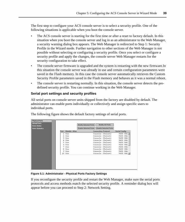
Chapter 5: Configuring the ACS Console Server in Wizard Mode 39
The first step to configure your ACS console server is to select a security profile. One of the following situations is applicable when you boot the console server.
• The ACS console server is starting for the first time or after a reset to factory default. In this situation when you boot the console server and log in as an administrator to the Web Manager, a security warning dialog box appears. The Web Manager is redirected to Step 1: Security Profile in the Wizard mode. Further navigation to other sections of the Web Manager is not possible without selecting or configuring a security profile. Once you select or configure a security profile and apply the changes, the console server Web Manager restarts for the security configuration to take effect.
• The console server firmware is upgraded and the system is restarting with the new firmware.In this situation the console server was already in use and certain configuration parameters were saved in the Flash memory. In this case the console server automatically retrieves the Custom Security Profile parameters saved in the Flash memory and behaves as it was a normal reboot.
• The console server is restarting normally. In this situation, the console server detects the pre-defined security profile. You can continue working in the Web Manager.
Serial port settings and security profiles
All serial ports on console server units shipped from the factory are disabled by default. The administrator can enable ports individually or collectively and assign specific users to individual ports.
The following figure shows the default factory settings of serial ports.
Figure 5.1: Administrator - Physical Ports Factory Settings
If you reconfigure the security profile and restart the Web Manager, make sure the serial ports protocols and access methods match the selected security profile. A reminder dialog box will appear before you can proceed to Step 2: Network Setting.
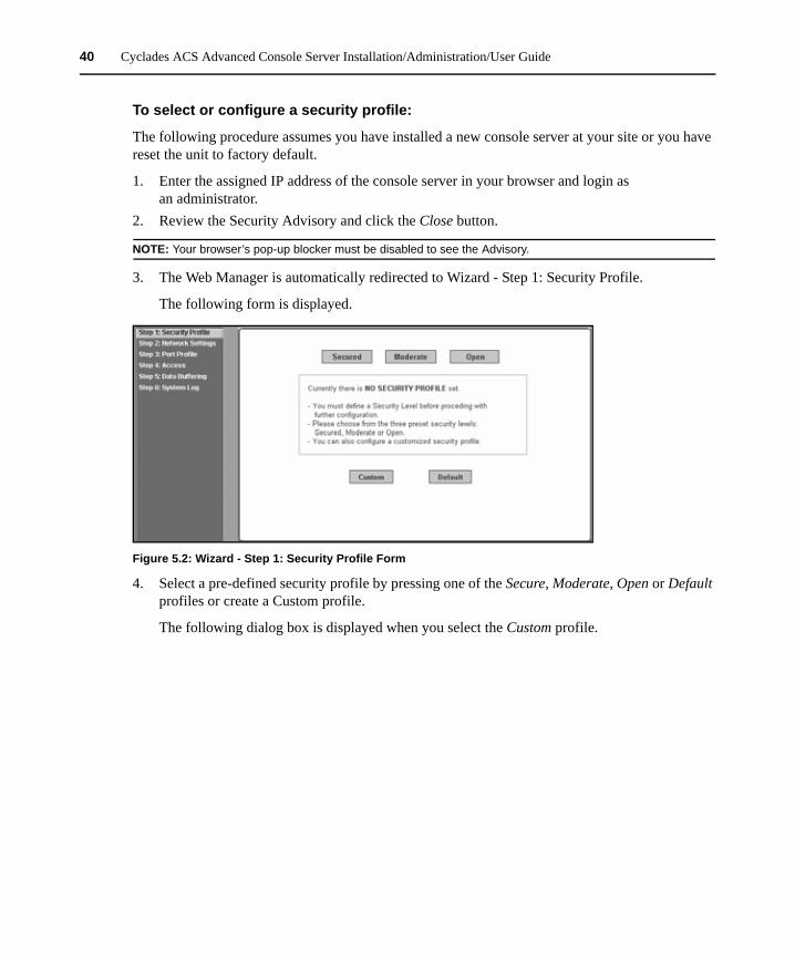
40 Cyclades ACS Advanced Console Server Installation/Administration/User Guide
To select or configure a security profile:
The following procedure assumes you have installed a new console server at your site or you have reset the unit to factory default.
1. Enter the assigned IP address of the console server in your browser and login as an administrator.
2. Review the Security Advisory and click the Close button.
NOTE: Your browser’s pop-up blocker must be disabled to see the Advisory.
3. The Web Manager is automatically redirected to Wizard - Step 1: Security Profile.
The following form is displayed.
Figure 5.2: Wizard - Step 1: Security Profile Form
4. Select a pre-defined security profile by pressing one of the Secure, Moderate, Open or Default profiles or create a Custom profile.
The following dialog box is displayed when you select the Custom profile.
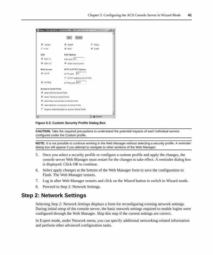
Chapter 5: Configuring the ACS Console Server in Wizard Mode 41
Figure 5.3: Custom Security Profile Dialog Box
CAUTION: Take the required precautions to understand the potential impacts of each individual service configured under the Custom profile.
NOTE: It is not possible to continue working in the Web Manager without selecting a security profile. A reminder dialog box will appear if you attempt to navigate to other sections of the Web Manager.
5. Once you select a security profile or configure a custom profile and apply the changes, the console server Web Manager must restart for the changes to take effect. A reminder dialog box is displayed. Click OK to continue.
6. Select apply changes at the bottom of the Web Manager form to save the configuration to Flash. The Web Manager restarts.
7. Log in after Web Manager restarts and click on the Wizard button to switch to Wizard mode.8. Proceed to Step 2: Network Settings.
Step 2: Network SettingsSelecting Step 2: Network Settings displays a form for reconfiguring existing network settings. During initial setup of the console server, the basic network settings required to enable logins were configured through the Web Manager. Skip this step if the current settings are correct.
In Expert mode, under Network menu, you can specify additional networking-related information and perform other advanced configuration tasks.
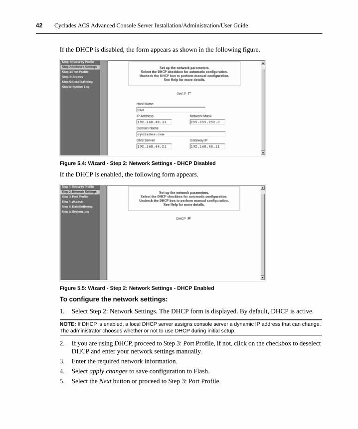
42 Cyclades ACS Advanced Console Server Installation/Administration/User Guide
If the DHCP is disabled, the form appears as shown in the following figure.
Figure 5.4: Wizard - Step 2: Network Settings - DHCP Disabled
If the DHCP is enabled, the following form appears.
Figure 5.5: Wizard - Step 2: Network Settings - DHCP Enabled
To configure the network settings:
1. Select Step 2: Network Settings. The DHCP form is displayed. By default, DHCP is active.
NOTE: If DHCP is enabled, a local DHCP server assigns console server a dynamic IP address that can change. The administrator chooses whether or not to use DHCP during initial setup.
2. If you are using DHCP, proceed to Step 3: Port Profile, if not, click on the checkbox to deselect DHCP and enter your network settings manually.
3. Enter the required network information. 4. Select apply changes to save configuration to Flash. 5. Select the Next button or proceed to Step 3: Port Profile.
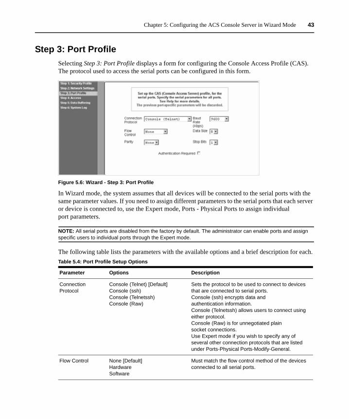
Chapter 5: Configuring the ACS Console Server in Wizard Mode 43
Step 3: Port ProfileSelecting Step 3: Port Profile displays a form for configuring the Console Access Profile (CAS). The protocol used to access the serial ports can be configured in this form.
Figure 5.6: Wizard - Step 3: Port Profile
In Wizard mode, the system assumes that all devices will be connected to the serial ports with the same parameter values. If you need to assign different parameters to the serial ports that each server or device is connected to, use the Expert mode, Ports - Physical Ports to assign individual port parameters.
NOTE: All serial ports are disabled from the factory by default. The administrator can enable ports and assign specific users to individual ports through the Expert mode.
The following table lists the parameters with the available options and a brief description for each.Table 5.4: Port Profile Setup Options
Parameter Options Description
Connection Protocol
Console (Telnet) [Default] Console (ssh) Console (Telnetssh) Console (Raw)
Sets the protocol to be used to connect to devices that are connected to serial ports. Console (ssh) encrypts data and authentication information. Console (Telnetssh) allows users to connect using either protocol. Console (Raw) is for unnegotiated plain socket connections. Use Expert mode if you wish to specify any of several other connection protocols that are listed under Ports-Physical Ports-Modify-General.
Flow Control None [Default] Hardware Software
Must match the flow control method of the devices connected to all serial ports.
44 Cyclades ACS Advanced Console Server Installation/Administration/User Guide
Expert mode provides additional options for custom configuration of serial ports, such as assigning an alias to a serial port, specifying individual parameters to the serial ports (or groups of serial ports) or using any of several other connection protocols.
To set parameters for all serial ports:
This step configures all serial ports with the same values. Use this form if all the devices connected to the serial ports on the console server can run using the same connection protocol with the same speed. Also, make sure the values you specify here are the same as those in effect on the connected devices.
If the connected devices require different connection protocols and speed, configure individual settings in Expert mode - Ports - Physical Ports.
1. Change network parameters as needed.2. To change whether authentication is required, check the Authentication Required checkbox to
enable or leave it unchecked to disable.3. Select apply changes to save configuration to Flash.4. Select the Next button or proceed to the next section, Step 4: Access.
Step 4: AccessSelecting Step 4: Access displays the form shown in the following figure that enables you to add or delete user accounts and set or change existing passwords.
Parity None [Default] Odd Even
Must match the parity used by the devices connected to all serial ports.
Baud Rate (Kbps) 9600 [Default]Options range from 2400–921600 Kbps
Must match the baud rates of the devices connected to all serial ports.
Data Size 8 [Default]Options range from 5–8
Must match the number of data bits used by the devices connected to all ports.
Stop Bits 1 [Default]Options are either 1 or 2
Must match the number of stop bits used by the devices connected to all ports.
Authentication Required
Check for enabled. Unchecked for disabled. [Default]
If the Authentication Required is enabled, user authentication is enforced using the local passwd database. To specify other authentication methods such as RADIUS, TACACS+, LDAP, Kerberos or NIS go to Expert mode and select Security-Authentication.
Table 5.4: Port Profile Setup Options (Continued)
Parameter Options Description
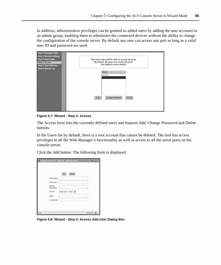
Chapter 5: Configuring the ACS Console Server in Wizard Mode 45
In addition, administrative privileges can be granted to added users by adding the user accounts to an admin group, enabling them to administer the connected devices without the ability to change the configuration of the console server. By default any user can access any port as long as a valid user ID and password are used.
Figure 5.7: Wizard - Step 4: Access
The Access form lists the currently defined users and features Add, Change Password and Delete buttons.
In the Users list by default, there is a root account that cannot be deleted. The root has access privileges to all the Web Manager’s functionality as well as access to all the serial ports on the console server.
Click the Add button. The following form is displayed.
Figure 5.8: Wizard - Step 4: Access Add User Dialog Box
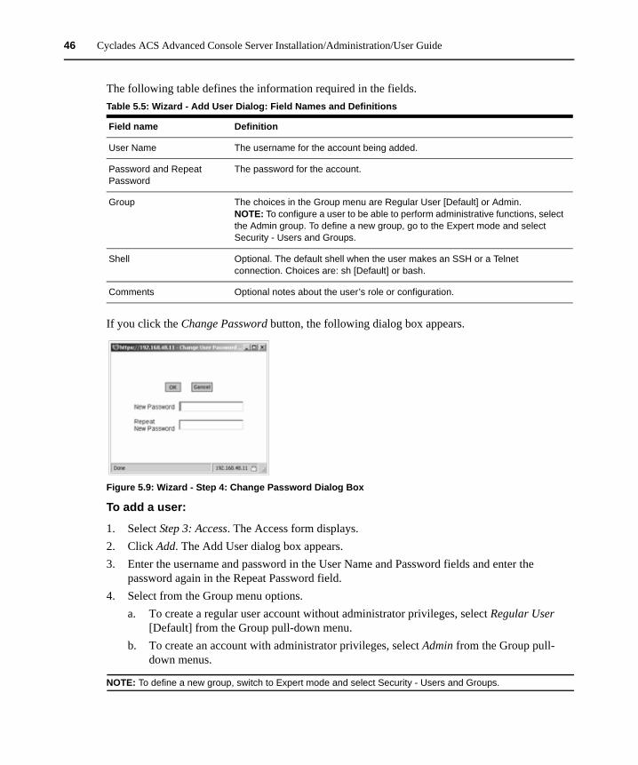
46 Cyclades ACS Advanced Console Server Installation/Administration/User Guide
The following table defines the information required in the fields.
If you click the Change Password button, the following dialog box appears.
Figure 5.9: Wizard - Step 4: Change Password Dialog Box
To add a user:
1. Select Step 3: Access. The Access form displays.2. Click Add. The Add User dialog box appears.3. Enter the username and password in the User Name and Password fields and enter the
password again in the Repeat Password field.4. Select from the Group menu options.
a. To create a regular user account without administrator privileges, select Regular User [Default] from the Group pull-down menu.
b. To create an account with administrator privileges, select Admin from the Group pull-down menus.
NOTE: To define a new group, switch to Expert mode and select Security - Users and Groups.
Table 5.5: Wizard - Add User Dialog: Field Names and Definitions
Field name Definition
User Name The username for the account being added.
Password and Repeat Password
The password for the account.
Group The choices in the Group menu are Regular User [Default] or Admin.NOTE: To configure a user to be able to perform administrative functions, select the Admin group. To define a new group, go to the Expert mode and select Security - Users and Groups.
Shell Optional. The default shell when the user makes an SSH or a Telnet connection. Choices are: sh [Default] or bash.
Comments Optional notes about the user’s role or configuration.
Chapter 5: Configuring the ACS Console Server in Wizard Mode 47
5. Enter the default shell in the Shell field (optional).6. Enter comments to identify the user’s role or configuration in the Comments field (optional).7. Click OK. 8. Click the apply changes button.
To delete a user:
1. Select Step 3: Access. The Access form displays.2. Select the username to delete.3. Click Delete. 4. Click apply changes.
To change a password:
CAUTION: Leaving the default root password unchanged leaves the console server and connected devices open to anyone who knows the default password and the console server’s IP address. For security reasons, change the root password from the default tslinux as soon as possible.
1. Select Step 3: Access. The Access form displays.2. Select the name of the user whose password you wish to change.3. Click Change Password. The Change User Password dialog box displays.4. Enter the new password in both fields and click OK.5. Click apply changes.
Step 5: Data BufferingSelecting Step 5: Data Buffering displays a form to allow logging the console data to a data buffer file either locally in the console server or remotely to an external storage source such as an NFS server or Syslog server. Once Enable Data Buffering is selected, the form displays a number of fields. The displayed fields depends on whether selected Destination is Local or Remote.
The values set in this form apply to all serial ports. Data buffering allows a site to save a record of all communication during a serial port connection session. You can set up data buffer files to be stored either in local files on the console server’s Flash memory or on the hard disk of an external server, such as an NFS or Syslog server.
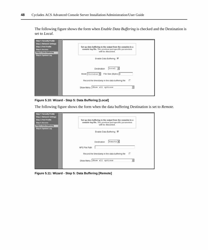
48 Cyclades ACS Advanced Console Server Installation/Administration/User Guide
The following figure shows the form when Enable Data Buffering is checked and the Destination is set to Local.
Figure 5.10: Wizard - Step 5: Data Buffering [Local]
The following figure shows the form when the data buffering Destination is set to Remote.
Figure 5.11: Wizard - Step 5: Data Buffering [Remote]
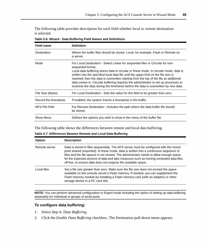
Chapter 5: Configuring the ACS Console Server in Wizard Mode 49
The following table provides description for each field whether local or remote destination is selected.
The following table shows the differences between remote and local data buffering.
NOTE: You can perform advanced configuration in Expert mode including the option of setting up data buffering separately for individual or groups of serial ports.
To configure data buffering:
1. Select Step 4: Data Buffering.2. Click the Enable Data Buffering checkbox. The Destination pull-down menu appears.
Table 5.6: Wizard - Data Buffering Field Names and Definitions
Field name Definition
Destination Where the buffer files should be stored. Local, for example, Flash or Remote on a server.
Mode For Local Destination - Select Linear for sequential files or Circular for non-sequential format. Local data buffering stores data in circular or linear mode. In circular mode, data is written into the specified local data file until the upper limit on the file size is reached; then the data is overwritten starting from the top of the file as additional data comes in. Circular buffering requires the administrator to set up processes to examine the data during the timeframe before the data is overwritten by new data.
File Size (Bytes) For Local Destination - Sets the value for this field to be greater than zero.
Record the timestamp If enabled, the system inserts a timestamp in the buffer.
NFS File Path For Remote Destination - Includes the path where the data buffer file should be stored.
Show Menu Defines the options you wish to show in the menu of the buffer file.
Table 5.7: Differences Beween Remote and Local Data Buffering
Option Description
Remote server Data is stored in files sequentially. The NFS server must be configured with the mount point shared (exported). In linear mode, data is written into a continuous sequence of files and the file spaces is not reused. The administrator needs to allow enough space for the expected amount of data and take measures such as moving unneeded data files off line, to ensure data does not outgrow the available space.
Local files Set a file size greater than zero. Make sure the file size does not exceed the space available on the console server’s Flash memory. If needed, you can supplement the Flash memory module by installing a Flash memory card (with an adaptor) or other storage device in a PC card slot.
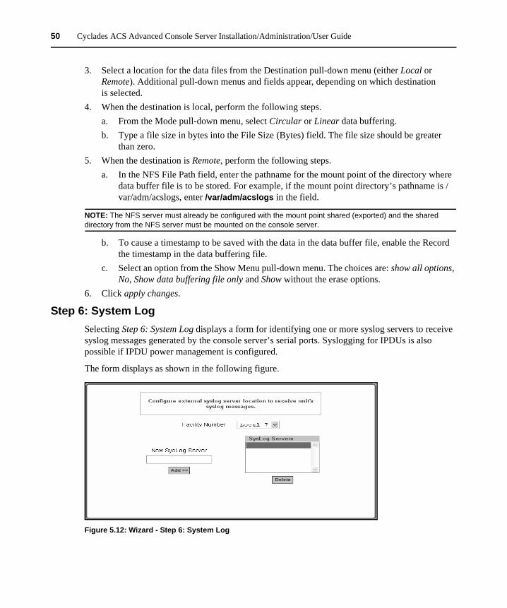
50 Cyclades ACS Advanced Console Server Installation/Administration/User Guide
3. Select a location for the data files from the Destination pull-down menu (either Local or Remote). Additional pull-down menus and fields appear, depending on which destination is selected.
4. When the destination is local, perform the following steps.a. From the Mode pull-down menu, select Circular or Linear data buffering.b. Type a file size in bytes into the File Size (Bytes) field. The file size should be greater
than zero.5. When the destination is Remote, perform the following steps.
a. In the NFS File Path field, enter the pathname for the mount point of the directory where data buffer file is to be stored. For example, if the mount point directory’s pathname is /var/adm/acslogs, enter /var/adm/acslogs in the field.
NOTE: The NFS server must already be configured with the mount point shared (exported) and the shared directory from the NFS server must be mounted on the console server.
b. To cause a timestamp to be saved with the data in the data buffer file, enable the Record the timestamp in the data buffering file.
c. Select an option from the Show Menu pull-down menu. The choices are: show all options, No, Show data buffering file only and Show without the erase options.
6. Click apply changes.
Step 6: System LogSelecting Step 6: System Log displays a form for identifying one or more syslog servers to receive syslog messages generated by the console server’s serial ports. Syslogging for IPDUs is also possible if IPDU power management is configured.
The form displays as shown in the following figure.
Figure 5.12: Wizard - Step 6: System Log
Chapter 5: Configuring the ACS Console Server in Wizard Mode 51
NOTE: To configure syslog with data buffering features for specific ports, switch to the Expert mode, Ports - Physical Ports - Modify Selected Ports - Data Buffering.
Before setting up syslogging, make sure a pre-configured syslog server is available on the same network as the console server. From the syslog server administrator, obtain the the IP address of the syslog server and the facility number for messages coming from the syslog server.
To add a syslog server:
This procedure assumes you have the IP address of the syslog server and the facility number for messages coming from the console server.
1. Select Step 6: System Log. The System Log form displays.2. From the Facility Number pull-down menu, select the facility number.3. In the New Syslog Server field, enter the IP address of a syslog server and then click the Add
button. (Repeat this step until all syslog servers are listed.)4. The new server(s) appears in the Syslog Servers list. 5. Click apply changes.
To delete a syslog server:
1. From the Syslog Server list, select the syslog server that you wish to delete from the current facility location and then click Delete.
2. Click apply changes.

52 Cyclades ACS Advanced Console Server Installation/Administration/User Guide
53
CHAPTER
6 Applications
Configuring the Console Server in Expert ModeMost applications require that you set the Web Manager to Expert mode. If you are in Wizard mode and need to perform advanced configuration, click the Expert button at the bottom of the left menu panel to switch to Expert mode. If the Wizard button displays at the lower left of the screen, you are in Expert mode.
Overview of menus and formsFigure 6.1 shows a typical Expert mode screen. The top menu bar contains the primary commands and the left menu panel contains the secondary commands. Based on what you select from the top menu bar, the left menu panel selections change accordingly and the form area may include tabs for other options as shown.
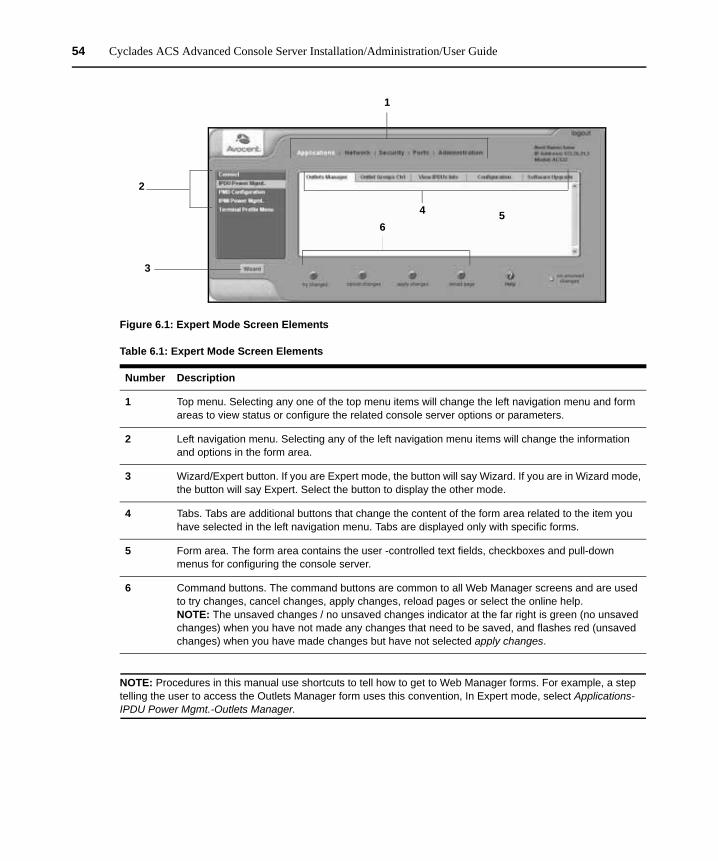
54 Cyclades ACS Advanced Console Server Installation/Administration/User Guide
Figure 6.1: Expert Mode Screen Elements
NOTE: Procedures in this manual use shortcuts to tell how to get to Web Manager forms. For example, a step telling the user to access the Outlets Manager form uses this convention, In Expert mode, select Applications- IPDU Power Mgmt.-Outlets Manager.
Table 6.1: Expert Mode Screen Elements
Number Description
1 Top menu. Selecting any one of the top menu items will change the left navigation menu and form areas to view status or configure the related console server options or parameters.
2 Left navigation menu. Selecting any of the left navigation menu items will change the information and options in the form area.
3 Wizard/Expert button. If you are Expert mode, the button will say Wizard. If you are in Wizard mode, the button will say Expert. Select the button to display the other mode.
4 Tabs. Tabs are additional buttons that change the content of the form area related to the item you have selected in the left navigation menu. Tabs are displayed only with specific forms.
5 Form area. The form area contains the user -controlled text fields, checkboxes and pull-down menus for configuring the console server.
6 Command buttons. The command buttons are common to all Web Manager screens and are used to try changes, cancel changes, apply changes, reload pages or select the online help.NOTE: The unsaved changes / no unsaved changes indicator at the far right is green (no unsaved changes) when you have not made any changes that need to be saved, and flashes red (unsaved changes) when you have made changes but have not selected apply changes.
3
2
1
46
5
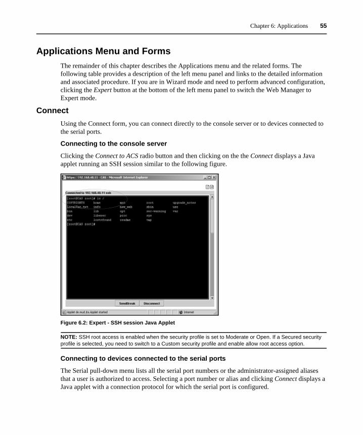
Chapter 6: Applications 55
Applications Menu and FormsThe remainder of this chapter describes the Applications menu and the related forms. The following table provides a description of the left menu panel and links to the detailed information and associated procedure. If you are in Wizard mode and need to perform advanced configuration, clicking the Expert button at the bottom of the left menu panel to switch the Web Manager to Expert mode.
ConnectUsing the Connect form, you can connect directly to the console server or to devices connected to the serial ports.
Connecting to the console server
Clicking the Connect to ACS radio button and then clicking on the the Connect displays a Java applet running an SSH session similar to the following figure.
Figure 6.2: Expert - SSH session Java Applet
NOTE: SSH root access is enabled when the security profile is set to Moderate or Open. If a Secured security profile is selected, you need to switch to a Custom security profile and enable allow root access option.
Connecting to devices connected to the serial ports
The Serial pull-down menu lists all the serial port numbers or the administrator-assigned aliases that a user is authorized to access. Selecting a port number or alias and clicking Connect displays a Java applet with a connection protocol for which the serial port is configured.
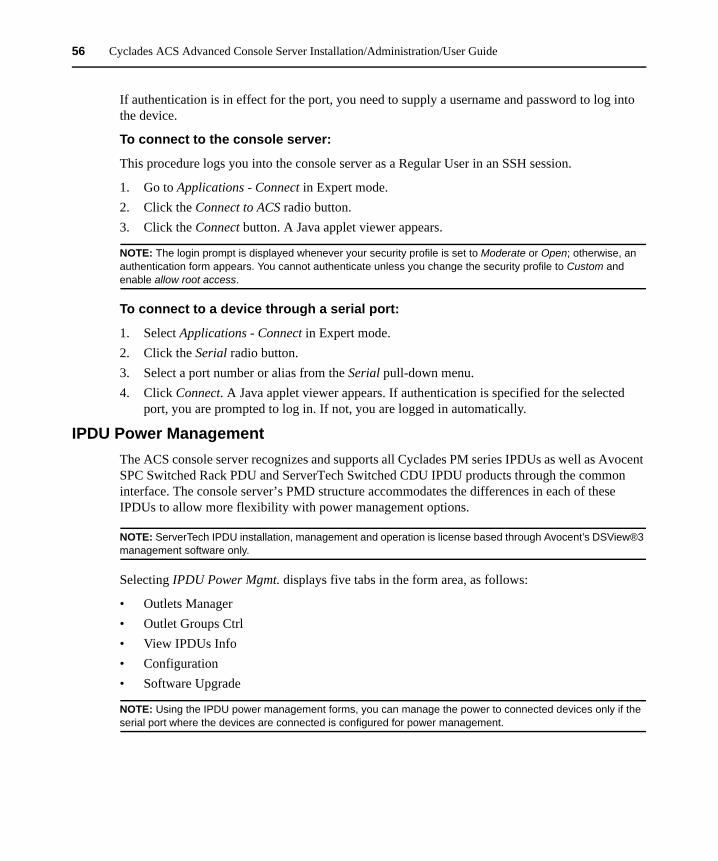
56 Cyclades ACS Advanced Console Server Installation/Administration/User Guide
If authentication is in effect for the port, you need to supply a username and password to log into the device.
To connect to the console server:
This procedure logs you into the console server as a Regular User in an SSH session.
1. Go to Applications - Connect in Expert mode.2. Click the Connect to ACS radio button.3. Click the Connect button. A Java applet viewer appears.
NOTE: The login prompt is displayed whenever your security profile is set to Moderate or Open; otherwise, an authentication form appears. You cannot authenticate unless you change the security profile to Custom and enable allow root access.
To connect to a device through a serial port:
1. Select Applications - Connect in Expert mode.2. Click the Serial radio button.3. Select a port number or alias from the Serial pull-down menu. 4. Click Connect. A Java applet viewer appears. If authentication is specified for the selected
port, you are prompted to log in. If not, you are logged in automatically.
IPDU Power ManagementThe ACS console server recognizes and supports all Cyclades PM series IPDUs as well as Avocent SPC Switched Rack PDU and ServerTech Switched CDU IPDU products through the common interface. The console server’s PMD structure accommodates the differences in each of these IPDUs to allow more flexibility with power management options.
NOTE: ServerTech IPDU installation, management and operation is license based through Avocent’s DSView®3 management software only.
Selecting IPDU Power Mgmt. displays five tabs in the form area, as follows:
• Outlets Manager• Outlet Groups Ctrl• View IPDUs Info• Configuration• Software Upgrade
NOTE: Using the IPDU power management forms, you can manage the power to connected devices only if the serial port where the devices are connected is configured for power management.
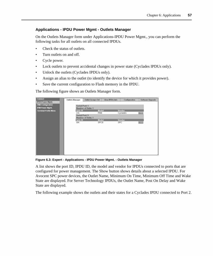
Chapter 6: Applications 57
Applications - IPDU Power Mgmt - Outlets Manager
On the Outlets Manager form under Applications-IPDU Power Mgmt., you can perform the following tasks for all outlets on all connected IPDUs.
• Check the status of outlets.• Turn outlets on and off.• Cycle power.• Lock outlets to prevent accidental changes in power state (Cyclades IPDUs only).• Unlock the outlets (Cyclades IPDUs only).• Assign an alias to the outlet (to identify the device for which it provides power).• Save the current configuration to Flash memory in the IPDU.
The following figure shows an Outlets Manager form.
Figure 6.3: Expert - Applications - IPDU Power Mgmt. - Outlets Manager
A list shows the port ID, IPDU ID, the model and vendor for IPDUs connected to ports that are configured for power management. The Show button shows details about a selected IPDU. For Avocent SPC power devices, the Outlet Name, Minimum On Time, Minimum Off Time and Wake State are displayed. For Server Technology IPDUs, the Outlet Name, Post On Delay and Wake State are displayed.
The following example shows the outlets and their states for a Cyclades IPDU connected to Port 2.
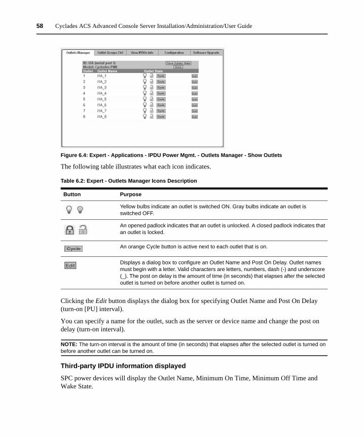
58 Cyclades ACS Advanced Console Server Installation/Administration/User Guide
Figure 6.4: Expert - Applications - IPDU Power Mgmt. - Outlets Manager - Show Outlets
The following table illustrates what each icon indicates.
Clicking the Edit button displays the dialog box for specifying Outlet Name and Post On Delay (turn-on [PU] interval).
You can specify a name for the outlet, such as the server or device name and change the post on delay (turn-on interval).
NOTE: The turn-on interval is the amount of time (in seconds) that elapses after the selected outlet is turned on before another outlet can be turned on.
Third-party IPDU information displayed
SPC power devices will display the Outlet Name, Minimum On Time, Minimum Off Time and Wake State.
Table 6.2: Expert - Outlets Manager Icons Description
Button Purpose
Yellow bulbs indicate an outlet is switched ON. Gray bulbs indicate an outlet is switched OFF.
An opened padlock indicates that an outlet is unlocked. A closed padlock indicates that an outlet is locked.
An orange Cycle button is active next to each outlet that is on.
Displays a dialog box to configure an Outlet Name and Post On Delay. Outlet names must begin with a letter. Valid characters are letters, numbers, dash (-) and underscore (_). The post on delay is the amount of time (in seconds) that elapses after the selected outlet is turned on before another outlet is turned on.

Chapter 6: Applications 59
ServerTech IPDUs will display Outlet Name, Post On Delay and Wake State.
To view status, lock, unlock, rename or cycle power outlets:
NOTE: For a group of outlets, the Cycle button operates only if all outlets of the group are turned ON.
1. Select Expert - Applications - IPDU Power Mgmt. - Outlets Manager. The Outlets Manager screen appears with each IPDU listed.
2. Click the Show button associated with the IPDU whose outlets you want to manage. A list of outlets appears.
3. To switch an outlet (or an outlet group) on or off, click its light bulb icon.
NOTE: For Avocent SPC power devices or Server Technology IPDUs, an alert window prompts you that you may need to refresh your browser to view the change in the Outlets Manager. Click OK and continue.
4. To lock or unlock an outlet (or an outlet group), click its padlock icon.
NOTE: The outlet locking function is available on Cyclades IPDUs only.
5. To cycle power to an outlet, click the adjacent Cycle button.6. To change the outlet’s name or the Post On Delay, click the adjacent Edit button. The Edit
Outlet dialog box appears.a. To change the name assigned to the outlet, enter a new name in the Outlet Name field.
Names must begin with a letter. Valid characters are letters, numbers, dash (-) and underscore (_).
b. To change the Post On Delay, change the default 0.50 number of seconds in the Post On Delay field.
NOTE: An outlet name should not be changed if the new outlet name is used elsewhere.
7. Click OK.8. Click the Save Outlets State button (saves outlet states to the IPDU only).9. Click apply changes.
NOTE: For Avocent SPC power devices or Server Technology IPDUs, an alert window prompts you that the screen is automatically reloaded. Click OK and wait for confirmation that the page has been reloaded.
Applications - IPDU Power Mgmt. - Outlets Group CtrlAn administrator can select Expert - Applications - IPDU Power Mgmt. - Outlet Groups Ctrl to view the status of outlet groups and turn power off and then on again for an entire group of outlets.
NOTE: Outlet groups can be defined under PMD Configuration - Outlet Groups.
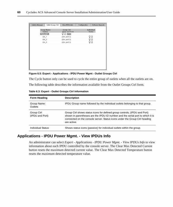
60 Cyclades ACS Advanced Console Server Installation/Administration/User Guide
Figure 6.5: Expert - Applications - IPDU Power Mgmt - Outlet Groups Ctrl
The Cycle button only can be used to cycle the entire group of outlets when all the outlets are on.
The following table describes the information available from the Outlet Groups Ctrl form.
Applications - IPDU Power Mgmt. - View IPDUs InfoAn administrator can select Expert - Applications - IPDU Power Mgmt. - View IPDUs Info to view information about each IPDU controlled by the console server. The Clear Max Detected Current button resets the maximum detected current value. The Clear Max Detected Temperature button resets the maximum detected temperature value.
Table 6.3: Expert - Outlet Groups Ctrl Information
Form Heading Description
Group Name: Outlets
IPDU Group name followed by the individual outlets belonging to that group.
Group Ctrl(IPDU and Port)
Group Ctrl shows status icons for defined group controls; (IPDU and Port) shown in parentheses are the IPDU ID number and the serial port to which it is connected on the console server. Status icons under the Group Ctrl heading are active.
Individual Status Shows status icons (passive) for individual outlets within the group.
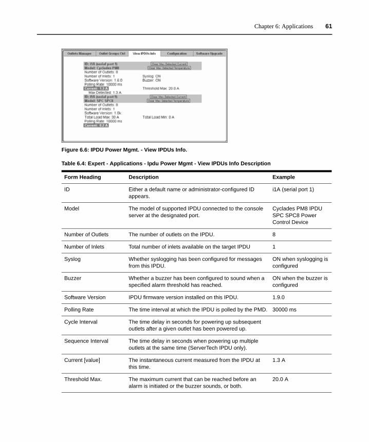
Chapter 6: Applications 61
Figure 6.6: IPDU Power Mgmt. - View IPDUs Info.
Table 6.4: Expert - Applications - Ipdu Power Mgmt - View IPDUs Info Description
Form Heading Description Example
ID Either a default name or administrator-configured ID appears.
i1A (serial port 1)
Model The model of supported IPDU connected to the console server at the designated port.
Cyclades PM8 IPDU SPC SPC8 Power Control Device
Number of Outlets The number of outlets on the IPDU. 8
Number of Inlets Total number of inlets available on the target IPDU 1
Syslog Whether syslogging has been configured for messages from this IPDU.
ON when syslogging is configured
Buzzer Whether a buzzer has been configured to sound when a specified alarm threshold has reached.
ON when the buzzer is configured
Software Version IPDU firmware version installed on this IPDU. 1.9.0
Polling Rate The time interval at which the IPDU is polled by the PMD. 30000 ms
Cycle Interval The time delay in seconds for powering up subsequent outlets after a given outlet has been powered up.
Sequence Interval The time delay in seconds when powering up multiple outlets at the same time (ServerTech IPDU only).
Current [value] The instantaneous current measured from the IPDU at this time.
1.3 A
Threshold Max. The maximum current that can be reached before an alarm is initiated or the buzzer sounds, or both.
20.0 A
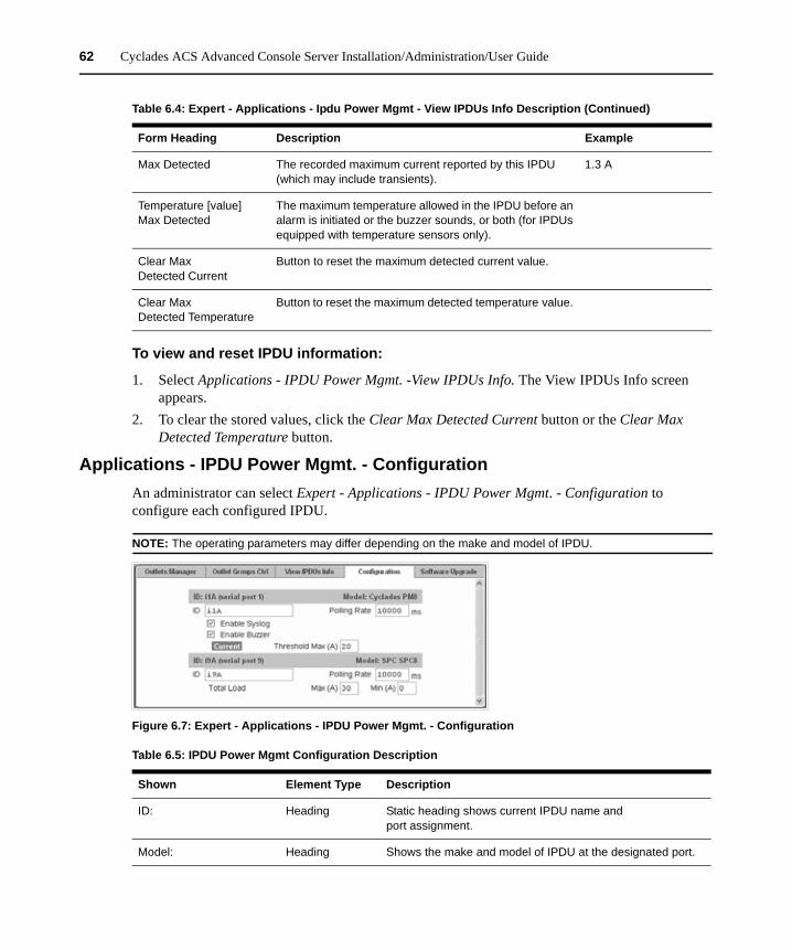
62 Cyclades ACS Advanced Console Server Installation/Administration/User Guide
To view and reset IPDU information:
1. Select Applications - IPDU Power Mgmt. -View IPDUs Info. The View IPDUs Info screen appears.
2. To clear the stored values, click the Clear Max Detected Current button or the Clear Max Detected Temperature button.
Applications - IPDU Power Mgmt. - ConfigurationAn administrator can select Expert - Applications - IPDU Power Mgmt. - Configuration to configure each configured IPDU.
NOTE: The operating parameters may differ depending on the make and model of IPDU.
Figure 6.7: Expert - Applications - IPDU Power Mgmt. - Configuration
Max Detected The recorded maximum current reported by this IPDU (which may include transients).
1.3 A
Temperature [value] Max Detected
The maximum temperature allowed in the IPDU before an alarm is initiated or the buzzer sounds, or both (for IPDUs equipped with temperature sensors only).
Clear Max Detected Current
Button to reset the maximum detected current value.
Clear Max Detected Temperature
Button to reset the maximum detected temperature value.
Table 6.4: Expert - Applications - Ipdu Power Mgmt - View IPDUs Info Description (Continued)
Form Heading Description Example
Table 6.5: IPDU Power Mgmt Configuration Description
Shown Element Type Description
ID: Heading Static heading shows current IPDU name and port assignment.
Model: Heading Shows the make and model of IPDU at the designated port.
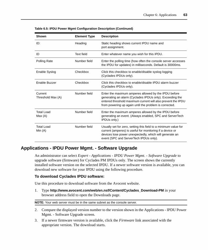
Chapter 6: Applications 63
Applications - IPDU Power Mgmt. - Software UpgradeAn administrator can select Expert - Applications - IPDU Power Mgmt. - Software Upgrade to upgrade software (firmware) for Cyclades PM IPDUs only. The screen shows the currently installed software version on the selected IPDU. If a newer software version is available, you can download new software for your IPDU using the following procedure.
To download Cyclades IPDU software:
Use this procedure to download software from the Avocent website.
1. Type http://www.avocent.com/web/en.nsf/Content/Cyclades_Download-PM in your browser address field to open the Downloads page.
NOTE: Your web server must be in the same subnet as the console server.
2. Compare the displayed version number to the version shown in the Applications - IPDU Power Mgmt. - Software Upgrade screen.
3. If a newer firmware version is available, click the Firmware link associated with the appropriate version. The download starts.
ID Text field Enter whatever name you wish for this IPDU.
Polling Rate Number field Enter the polling time (how often the console server accesses the IPDU for updates) in milliseconds. Default is 30000ms.
Enable Syslog Checkbox Click this checkbox to enable/disable syslog logging (Cyclades IPDUs only).
Enable Buzzer Checkbox Click this checkbox to enable/disable IPDU alarm buzzer (Cyclades IPDUs only).
Current Threshold Max (A)
Number field Enter the maximum amperes allowed by the IPDU before generating an alarm (Cyclades IPDUs only). Exceeding the entered threshold maximum current will also prevent the IPDU from powering up again until the problem is corrected.
Total LoadMax (A)
Number field Enter the maximum amperes allowed by the IPDU before generating an event. (Always enabled, SPC and ServerTech IPDUs only.)
Total LoadMin (A)
Number field Usually set for zero, setting this field to a minimum value for current (amperes) is useful for monitoring if a device or devices lose power unexpectedly, which will generate an event (SPC and ServerTech IPDUs only).
Table 6.5: IPDU Power Mgmt Configuration Description (Continued)
Shown Element Type Description
ID: Heading Static heading shows current IPDU name and port assignment.
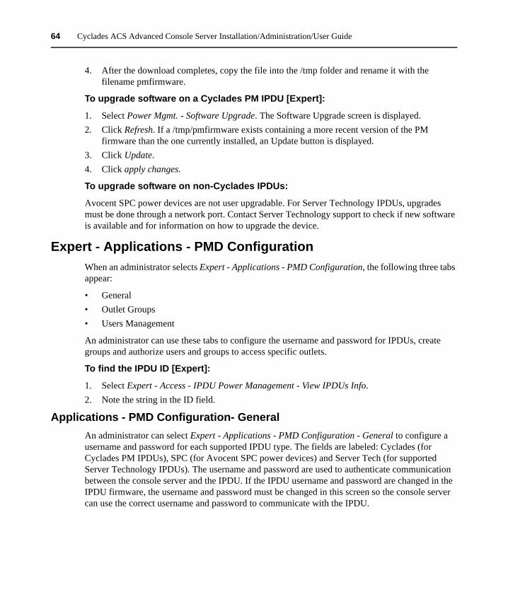
64 Cyclades ACS Advanced Console Server Installation/Administration/User Guide
4. After the download completes, copy the file into the /tmp folder and rename it with the filename pmfirmware.
To upgrade software on a Cyclades PM IPDU [Expert]:
1. Select Power Mgmt. - Software Upgrade. The Software Upgrade screen is displayed. 2. Click Refresh. If a /tmp/pmfirmware exists containing a more recent version of the PM
firmware than the one currently installed, an Update button is displayed. 3. Click Update.4. Click apply changes.
To upgrade software on non-Cyclades IPDUs:
Avocent SPC power devices are not user upgradable. For Server Technology IPDUs, upgrades must be done through a network port. Contact Server Technology support to check if new software is available and for information on how to upgrade the device.
Expert - Applications - PMD ConfigurationWhen an administrator selects Expert - Applications - PMD Configuration, the following three tabs appear:
• General• Outlet Groups• Users Management
An administrator can use these tabs to configure the username and password for IPDUs, create groups and authorize users and groups to access specific outlets.
To find the IPDU ID [Expert]:
1. Select Expert - Access - IPDU Power Management - View IPDUs Info.2. Note the string in the ID field.
Applications - PMD Configuration- GeneralAn administrator can select Expert - Applications - PMD Configuration - General to configure a username and password for each supported IPDU type. The fields are labeled: Cyclades (for Cyclades PM IPDUs), SPC (for Avocent SPC power devices) and Server Tech (for supported Server Technology IPDUs). The username and password are used to authenticate communication between the console server and the IPDU. If the IPDU username and password are changed in the IPDU firmware, the username and password must be changed in this screen so the console server can use the correct username and password to communicate with the IPDU.
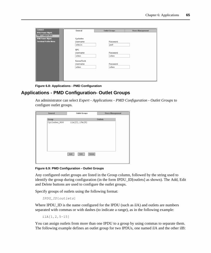
Chapter 6: Applications 65
Figure 6.8: Applications - PMD Configuration
Applications - PMD Configuration- Outlet GroupsAn administrator can select Expert - Applications - PMD Configuration - Outlet Groups to configure outlet groups.
Figure 6.9: PMD Configuration - Outlet Groups
Any configured outlet groups are listed in the Group column, followed by the string used to identify the group during configuration (in the form IPDU_ID[outlets] as shown). The Add, Edit and Delete buttons are used to configure the outlet groups.
Specify groups of outlets using the following format:
IPDU_ID[outlets]
Where IPDU_ID is the name configured for the IPDU (such as ilA) and outlets are numbers separated with commas or with dashes (to indicate a range), as in the following example:
ilA[1,2,5-15]
You can assign outlets from more than one IPDU to a group by using commas to separate them. The following example defines an outlet group for two IPDUs, one named ilA and the other ilB:
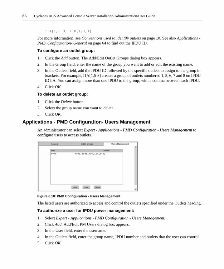
66 Cyclades ACS Advanced Console Server Installation/Administration/User Guide
ilA[1,5-8],ilB[1,3,4]
For more information, see Conventions used to identify outlets on page 10. See also Applications - PMD Configuration- General on page 64 to find out the IPDU ID.
To configure an outlet group:
1. Click the Add button. The Add/Edit Outlet Groups dialog box appears.2. In the Group field, enter the name of the group you want to add or edit the existing name.3. In the Outlets field, add the IPDU ID followed by the specific outlets to assign to the group in
brackets. For example, i1A[1,5-8] creates a group of outlets numbered 1, 5, 6, 7 and 8 on IPDU ID ilA. You can assign more than one IPDU to the group, with a comma between each IPDU.
4. Click OK.
To delete an outlet group:
1. Click the Delete button.2. Select the group name you want to delete.3. Click OK.
Applications - PMD Configuration- Users ManagementAn administrator can select Expert - Applications - PMD Configuration - Users Management to configure users to access outlets.
Figure 6.10: PMD Configuration - Users Management
The listed users are authorized to access and control the outlets specified under the Outlets heading.
To authorize a user for IPDU power management:
1. Select Expert - Applications - PMD Configuration - Users Management.2. Click Add. Add/Edit PM Users dialog box appears.3. In the User field, enter the username.4. In the Outlets field, enter the group name, IPDU number and outlets that the user can control. 5. Click OK.
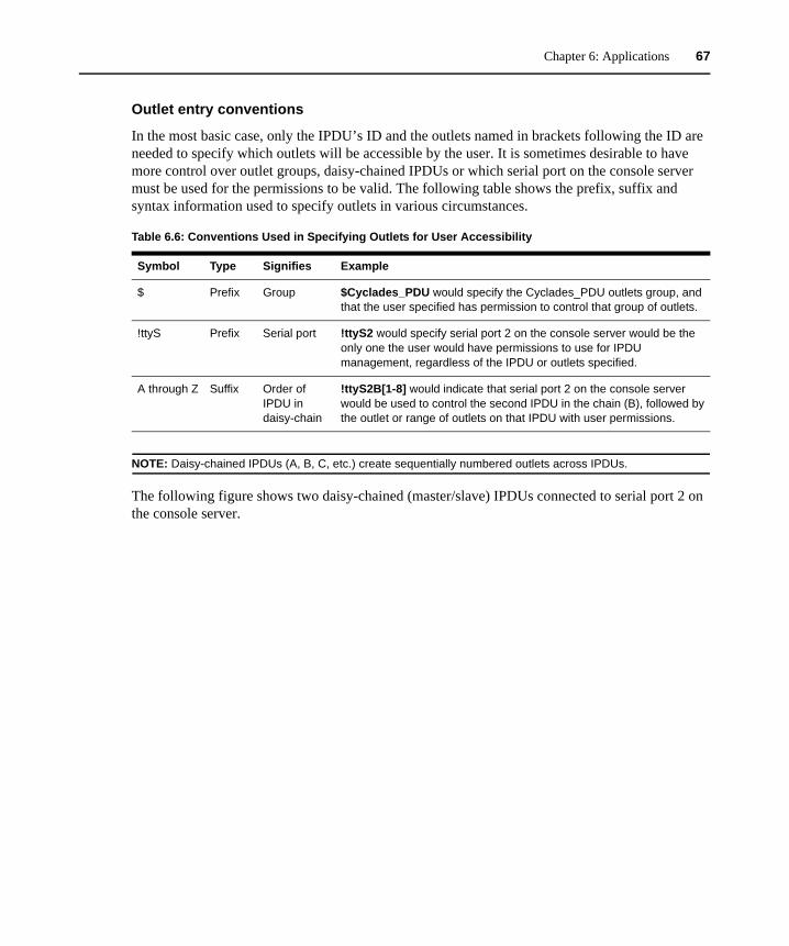
Chapter 6: Applications 67
Outlet entry conventions
In the most basic case, only the IPDU’s ID and the outlets named in brackets following the ID are needed to specify which outlets will be accessible by the user. It is sometimes desirable to have more control over outlet groups, daisy-chained IPDUs or which serial port on the console server must be used for the permissions to be valid. The following table shows the prefix, suffix and syntax information used to specify outlets in various circumstances.
NOTE: Daisy-chained IPDUs (A, B, C, etc.) create sequentially numbered outlets across IPDUs.
The following figure shows two daisy-chained (master/slave) IPDUs connected to serial port 2 on the console server.
Table 6.6: Conventions Used in Specifying Outlets for User Accessibility
Symbol Type Signifies Example
$ Prefix Group $Cyclades_PDU would specify the Cyclades_PDU outlets group, and that the user specified has permission to control that group of outlets.
!ttyS Prefix Serial port !ttyS2 would specify serial port 2 on the console server would be the only one the user would have permissions to use for IPDU management, regardless of the IPDU or outlets specified.
A through Z Suffix Order of IPDU in daisy-chain
!ttyS2B[1-8] would indicate that serial port 2 on the console server would be used to control the second IPDU in the chain (B), followed by the outlet or range of outlets on that IPDU with user permissions.
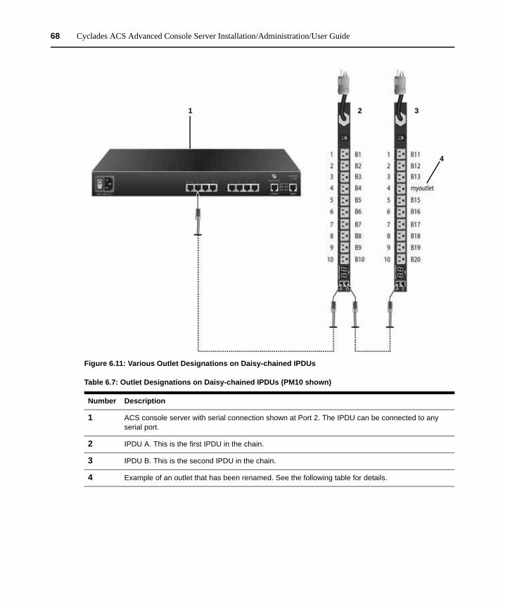
68 Cyclades ACS Advanced Console Server Installation/Administration/User Guide
Figure 6.11: Various Outlet Designations on Daisy-chained IPDUs
Table 6.7: Outlet Designations on Daisy-chained IPDUs (PM10 shown)
Number Description
1 ACS console server with serial connection shown at Port 2. The IPDU can be connected to any serial port.
2 IPDU A. This is the first IPDU in the chain.
3 IPDU B. This is the second IPDU in the chain.
4 Example of an outlet that has been renamed. See the following table for details.
1 2 3
4
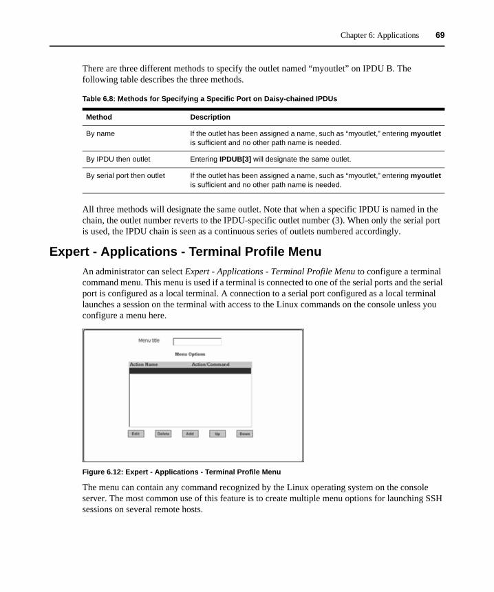
Chapter 6: Applications 69
There are three different methods to specify the outlet named “myoutlet” on IPDU B. The following table describes the three methods.
All three methods will designate the same outlet. Note that when a specific IPDU is named in the chain, the outlet number reverts to the IPDU-specific outlet number (3). When only the serial port is used, the IPDU chain is seen as a continuous series of outlets numbered accordingly.
Expert - Applications - Terminal Profile MenuAn administrator can select Expert - Applications - Terminal Profile Menu to configure a terminal command menu. This menu is used if a terminal is connected to one of the serial ports and the serial port is configured as a local terminal. A connection to a serial port configured as a local terminal launches a session on the terminal with access to the Linux commands on the console unless you configure a menu here.
Figure 6.12: Expert - Applications - Terminal Profile Menu
The menu can contain any command recognized by the Linux operating system on the console server. The most common use of this feature is to create multiple menu options for launching SSH sessions on several remote hosts.
Table 6.8: Methods for Specifying a Specific Port on Daisy-chained IPDUs
Method Description
By name If the outlet has been assigned a name, such as “myoutlet,” entering myoutlet is sufficient and no other path name is needed.
By IPDU then outlet Entering IPDUB[3] will designate the same outlet.
By serial port then outlet If the outlet has been assigned a name, such as “myoutlet,” entering myoutlet is sufficient and no other path name is needed.
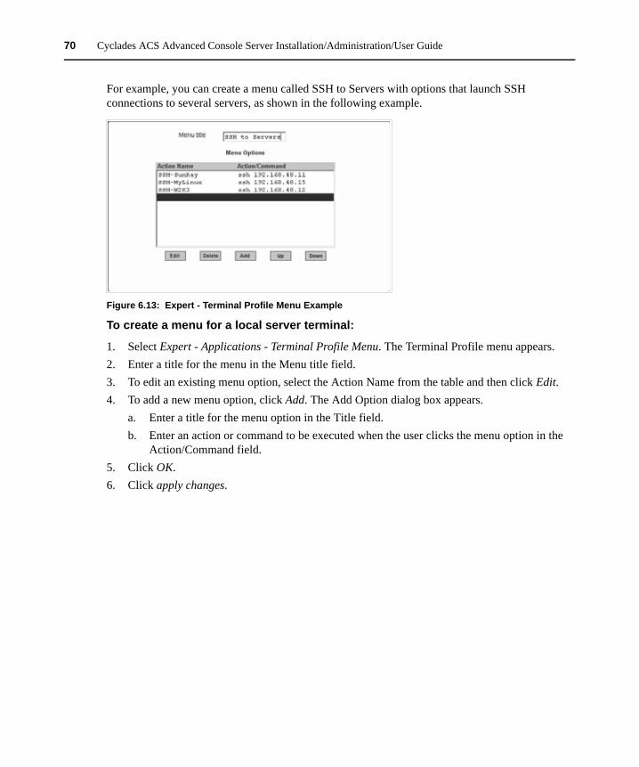
70 Cyclades ACS Advanced Console Server Installation/Administration/User Guide
For example, you can create a menu called SSH to Servers with options that launch SSH connections to several servers, as shown in the following example.
Figure 6.13: Expert - Terminal Profile Menu Example
To create a menu for a local server terminal:
1. Select Expert - Applications - Terminal Profile Menu. The Terminal Profile menu appears.2. Enter a title for the menu in the Menu title field.3. To edit an existing menu option, select the Action Name from the table and then click Edit.4. To add a new menu option, click Add. The Add Option dialog box appears.
a. Enter a title for the menu option in the Title field.b. Enter an action or command to be executed when the user clicks the menu option in the
Action/Command field.5. Click OK.6. Click apply changes.
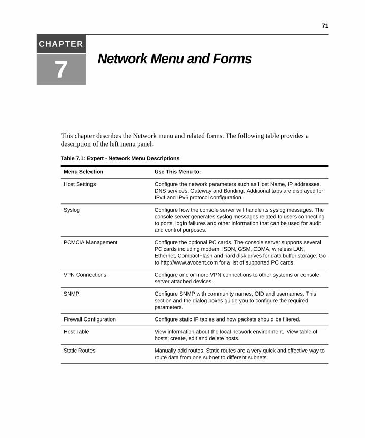
71
CHAPTER
7 Network Menu and Forms
This chapter describes the Network menu and related forms. The following table provides a description of the left menu panel.
Table 7.1: Expert - Network Menu Descriptions
Menu Selection Use This Menu to:
Host Settings Configure the network parameters such as Host Name, IP addresses, DNS services, Gateway and Bonding. Additional tabs are displayed for IPv4 and IPv6 protocol configuration.
Syslog Configure how the console server will handle its syslog messages. The console server generates syslog messages related to users connecting to ports, login failures and other information that can be used for audit and control purposes.
PCMCIA Management Configure the optional PC cards. The console server supports several PC cards including modem, ISDN, GSM, CDMA, wireless LAN, Ethernet, CompactFlash and hard disk drives for data buffer storage. Go to http://www.avocent.com for a list of supported PC cards.
VPN Connections Configure one or more VPN connections to other systems or console server attached devices.
SNMP Configure SNMP with community names, OID and usernames. This section and the dialog boxes guide you to configure the required parameters.
Firewall Configuration Configure static IP tables and how packets should be filtered.
Host Table View information about the local network environment. View table of hosts; create, edit and delete hosts.
Static Routes Manually add routes. Static routes are a very quick and effective way to route data from one subnet to different subnets.
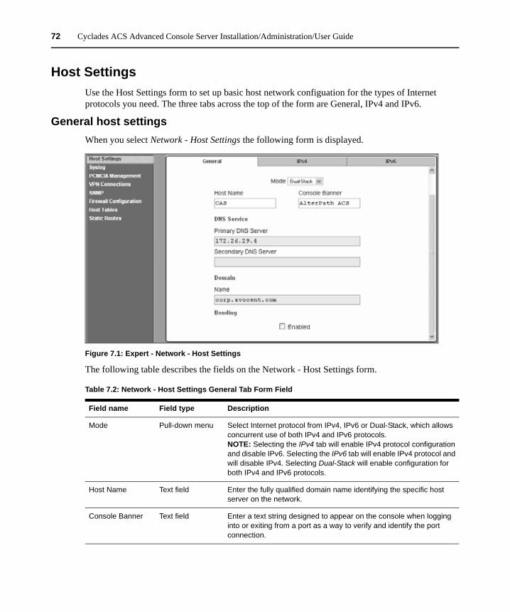
72 Cyclades ACS Advanced Console Server Installation/Administration/User Guide
Host SettingsUse the Host Settings form to set up basic host network configuation for the types of Internet protocols you need. The three tabs across the top of the form are General, IPv4 and IPv6.
General host settingsWhen you select Network - Host Settings the following form is displayed.
Figure 7.1: Expert - Network - Host Settings
The following table describes the fields on the Network - Host Settings form.
Table 7.2: Network - Host Settings General Tab Form Field
Field name Field type Description
Mode Pull-down menu Select Internet protocol from IPv4, IPv6 or Dual-Stack, which allows concurrent use of both IPv4 and IPv6 protocols.NOTE: Selecting the IPv4 tab will enable IPv4 protocol configuration and disable IPv6. Selecting the IPv6 tab will enable IPv4 protocol and will disable IPv4. Selecting Dual-Stack will enable configuration for both IPv4 and IPv6 protocols.
Host Name Text field Enter the fully qualified domain name identifying the specific host server on the network.
Console Banner Text field Enter a text string designed to appear on the console when logging into or exiting from a port as a way to verify and identify the port connection.
Chapter 7: Network Menu and Forms 73
NOTE: If you have set IP Filtering rules before bonding is activated, the interface reference in the firewall configuration will be eth0. You need to change the interface to bond0 in order to reference the bonded interface.
Disabling and enabling IPv4 or IPv6 protocolsThe ACS console server allows you to permanently enable or disable either IPv4 or IPv6 protocols during configuration from the Network - Host Settings - General Mode pull-down menu.
Disabling IPv4
If you disable IPv4, configuration of IPv4 addresses will not be allowed. A warning message will be displayed advising you that services not supporting IPv6 will be unavailable. The IPv4 tab will be disabled.
NOTE: If services not supporting IPv6 are needed, you will have to select Dual-Stack (IPv4 and IPv6) and those services will be available only for IPv4.
Disabling/Enabling IPv6
If you disable IPv6, configuration of IPv6 addresses will not be allowed and the IPv6 tab will be disabled. If you change IPv6 from disabled to enabled, a warning message will be displayed advising you that some services not supporting IPv6 will be unavailable and that you will have to configure those services supporting IPv6 for them to work properly.
NOTE: If services not supporting IPv6 are needed, you will have to select Dual-Stack (IPv4 and IPv6) and those services will be available only for IPv4.
DNS ServicePrimary DNS Server
Secondary DNS Server
Text field
Text field
Enter the address of the of the domain name server.
Enter the address of the backup domain name server, if used.
DomainName Text field Enter the name of the host domain.
Bonding Checkbox Click Enabled to enable bonding. Bonding provides redundancy for the Ethernet devices using the standard Ethernet interface as the primary mode of access and a PC card as a secondary mode of access. If bonding is enabled, the following values should be set:Miimon - The interval in which the active interface is checked to see if it is still communicating (in milliseconds).Updelay - The time that the system will wait to make the primary interface active after it has been detected as up (in milliseconds).
Table 7.2: Network - Host Settings General Tab Form Field (Continued)
Field name Field type Description
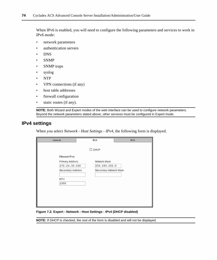
74 Cyclades ACS Advanced Console Server Installation/Administration/User Guide
When IPv6 is enabled, you will need to configure the following parameters and services to work in IPv6 mode:
• network parameters• authentication servers• DNS• SNMP• SNMP traps• syslog• NTP• VPN connections (if any)• host table addresses• firewall configuration• static routes (if any).
NOTE: Both Wizard and Expert modes of the web interface can be used to configure network parameters. Beyond the network parameters stated above, other services must be configured in Expert mode.
IPv4 settingsWhen you select Network - Host Settings - IPv4, the following form is displayed.
Figure 7.2: Expert - Network - Host Settings - IPv4 (DHCP disabled)
NOTE: If DHCP is checked, the rest of the form is disabled and will not be displayed.
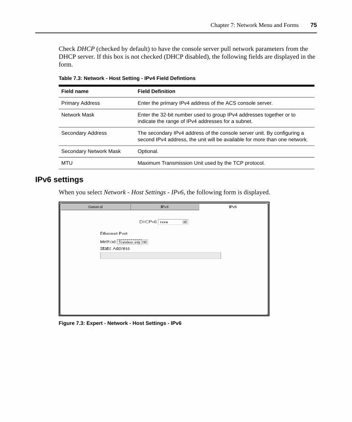
Chapter 7: Network Menu and Forms 75
Check DHCP (checked by default) to have the console server pull network parameters from the DHCP server. If this box is not checked (DHCP disabled), the following fields are displayed in the form.
IPv6 settingsWhen you select Network - Host Settings - IPv6, the following form is displayed.
Figure 7.3: Expert - Network - Host Settings - IPv6
Table 7.3: Network - Host Setting - IPv4 Field Defintions
Field name Field Definition
Primary Address Enter the primary IPv4 address of the ACS console server.
Network Mask Enter the 32-bit number used to group IPv4 addresses together or to indicate the range of IPv4 addresses for a subnet.
Secondary Address The secondary IPv4 address of the console server unit. By configuring a second IPv4 address, the unit will be available for more than one network.
Secondary Network Mask Optional.
MTU Maximum Transmission Unit used by the TCP protocol.
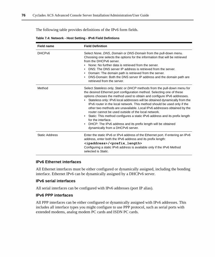
76 Cyclades ACS Advanced Console Server Installation/Administration/User Guide
The following table provides definitions of the IPv6 form fields.
IPv6 Ethernet interfaces
All Ethernet interfaces must be either configured or dynamically assigned, including the bonding interface. Ethernet IPv6 can be dynamically assigned by a DHCPv6 server.
IPv6 serial interfaces
All serial interfaces can be configured with IPv6 addresses (port IP alias).
IPv6 PPP interfaces
All PPP interfaces can be either configured or dynamically assigned with IPv6 addresses. This includes all interface types you might configure to use PPP protocol, such as serial ports with extended modems, analog modem PC cards and ISDN PC cards.
Table 7.4: Network - Host Setting - IPv6 Field Defintions
Field name Field Definition
DHCPv6 Select None, DNS, Domain or DNS-Domain from the pull-down menu. Choosing one selects the options for the information that will be retrieved from the DHCPv6 server.• None: No further data is retrieved from the server.• DNS: The DNS server IP address is retrieved from the server.• Domain: The domain path is retrieved from the server.• DNS-Domain: Both the DNS server IP address and the domain path are
retrieved from the server.
Method Select Stateless only, Static or DHCP methods from the pull-down menu for the desired Ethernet port configuration method. Selecting one of these options chooses the method used to obtain and configure IPv6 addresses.• Stateless only: IPv6 local addresses will be obtained dynamically from the
IPv6 router in the local network. This method should be used only if the other two methods are unavailable. Local IPv6 addresses obtained by the router cannot be used outside of the local network.
• Static: This method configures a static IPv6 address and its prefix length for the interface.
• DHCP: The IPv6 address and its prefix length will be obtained dynamically from a DHCPv6 server.
Static Address Enter the static IPv6 or IPv4 address of the Ethernet port. If entering an IPv6 address, enter both the IPv6 address and its prefix length:<ipaddress>/<prefix_length>Configuring a static IPv6 address is available only if the IPv6 Method selected is Static.
Chapter 7: Network Menu and Forms 77
Other interfaces
All interfaces other than Ethernet, bonding and PPP will also be configured with IPv6 addresses, including all sub-interfaces and virtual interfaces such as VPN tunnels (static IPSec tunnels). The following list shows the network services that will be configured to support the IPv6 protocol:
• Access to DNS servers• SNMP• Sending SNMP trap• Remote authentication (except to NIS)• Access to hosts• Stateful and stateless packet filtering (firewall)• Static routes• Sending messages and events to SMTP servers• Sending data to data buffering servers• Access to NTP server• FTP for configuration backup• FTP for firmware upgrade
NOTE: Virtual ports (virtualization) are not supported by IPv6.
To configure host settings [Expert] from the General form:
1. Go to Network - Host Settings. The Host Settings - General form appears.2. Select Dual-Stack, IPv4 or IPv6 from the Mode pull-down menu.
NOTE: If Dual-Stack is selected, both the IPv4 and IPv6 tabs will remain active and will run concurrently. Selecting IPv4 will disable the IPv6 tab, and selecting IPv6 will disable the IPv4 tab in the Host Settings form.
3. Enter the name assigned to the IP address of the console server in the Host Name field.4. Enter a console banner in the Console Banner field.5. Enter the Primary DNS Server IP address.6. Enter the Secondary DNS Server IP address, if used.7. Enter the domain in the Domain Name field.8. To enable Bonding (optional), click Enabled. If Bonding is not desired, leave Enabled
unchecked and go to Step 10.
NOTE: If Bonding is enabled, you may have to scroll down to see additional entries for Miimon and Updelay.
9. If you enabled Bonding, check the values for Miimon and Updelay and change them if necessary.
10. When finished, click apply changes.
78 Cyclades ACS Advanced Console Server Installation/Administration/User Guide
To configure IPv4 protocol:
1. If IPv4 is enabled (tab is active) select the IPv4 tab. The IPv4 form will be displayed.2. If configuring IPv4 using DHCP is desired, click the DHCP checkbox.
NOTE: If DHCP is enabled, all other fields on the form will not be displayed.
3. Under Ethernet Port, complete or edit the following fields as necessary.a. Enter the IP address of the console server in the Primary Address field.b. Enter the netmask in the Network Mask field.c. Enter the address of the secondary console server in the Secondary Address field, if used.d. Specify the network mask of the secondary IP in the Secondary Network Mask field. e. Specify the desired maximum transmission unit in the Maximum Transmission Unit field.
4. When finished, click apply changes.
To configure IPv6 protocol:
1. If IPv6 is enabled (tab is active), select the IPv6 tab. The IPv6 form will be displayed.2. From the DHCPv6 pull-down menu, select none, DNS, Domain or DNS-Domain. If DHCP is
selected, then the DHCP options will define the address configuration information is retrieved from the DHCPv6 server. DHCP options are:• none (only the IP address will be retrieved)• DNS (the DNS address will be retrieved from the DHCPv6 server)• Domain (the domain path will be retrieved from the DHCPv6 server)• DNS-Domain (both DNS server and domain path will be retrieved from the DHCPv6
server)
NOTE: If either DNS or DNS-Domain is selected, DNS Service and its associated fields will not be displayed.
3. Under Ethernet Port, complete or edit the following fields as necessary.a. Choose your configuration method from the Method pull-down menu. Choices are
Stateless only, Static or DHCP.
NOTE: It is recommended that Stateless only be used only when none of the other methods is available. This means that local configuration from the local router and only the link_local address will be available to the ACS console server.
b. If the DNS Service fields are active (none or Domain DHCP selected in Step 2) and Static has been selected under Ethernet Port, enter the Primary DNS server IP address. If there is a backup DNS server, enter the the address of the secondary DNS server in the Secondary DNS server field.
4. When finished, click apply changes.
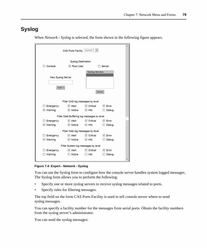
Chapter 7: Network Menu and Forms 79
SyslogWhen Network - Syslog is selected, the form shown in the following figure appears.
Figure 7.4: Expert - Network - Syslog
You can use the Syslog form to configure how the console server handles system logged messages. The Syslog form allows you to perform the following:
• Specify one or more syslog servers to receive syslog messages related to ports. • Specify rules for filtering messages.
The top field on the form CAS Ports Facility is used to tell console server where to send syslog messages.
You can specify a facility number for the messages from serial ports. Obtain the facility numbers from the syslog server’s administrator.
You can send the syslog messages:
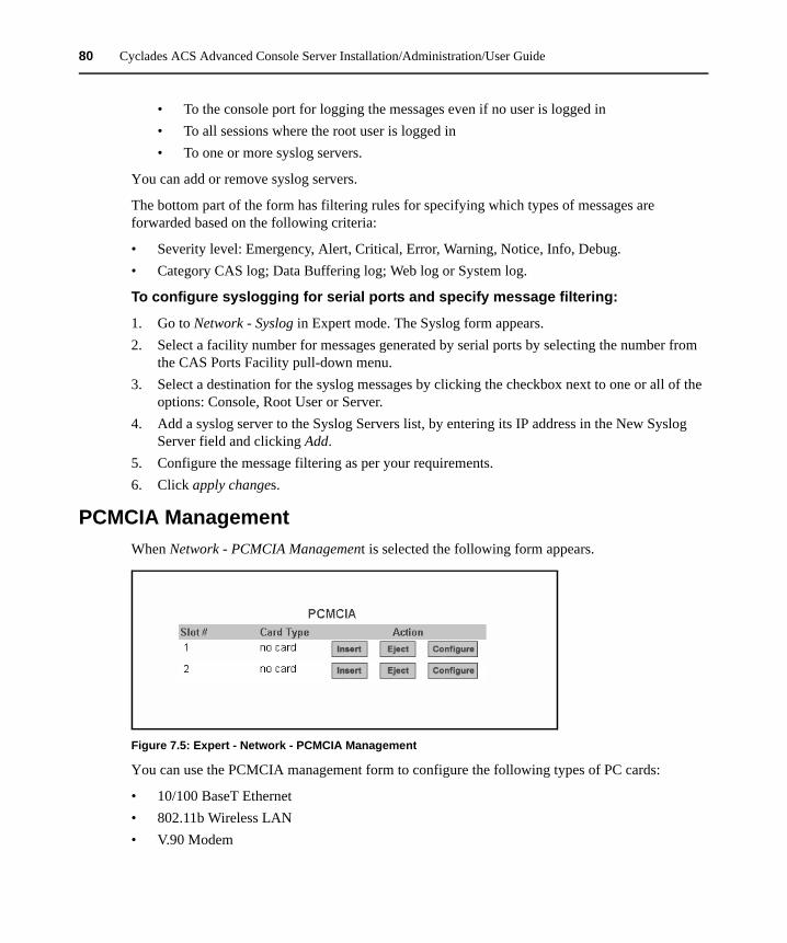
80 Cyclades ACS Advanced Console Server Installation/Administration/User Guide
• To the console port for logging the messages even if no user is logged in• To all sessions where the root user is logged in• To one or more syslog servers.
You can add or remove syslog servers.
The bottom part of the form has filtering rules for specifying which types of messages are forwarded based on the following criteria:
• Severity level: Emergency, Alert, Critical, Error, Warning, Notice, Info, Debug. • Category CAS log; Data Buffering log; Web log or System log.
To configure syslogging for serial ports and specify message filtering:
1. Go to Network - Syslog in Expert mode. The Syslog form appears.2. Select a facility number for messages generated by serial ports by selecting the number from
the CAS Ports Facility pull-down menu.3. Select a destination for the syslog messages by clicking the checkbox next to one or all of the
options: Console, Root User or Server.4. Add a syslog server to the Syslog Servers list, by entering its IP address in the New Syslog
Server field and clicking Add.5. Configure the message filtering as per your requirements.6. Click apply changes.
PCMCIA ManagementWhen Network - PCMCIA Management is selected the following form appears.
Figure 7.5: Expert - Network - PCMCIA Management
You can use the PCMCIA management form to configure the following types of PC cards:
• 10/100 BaseT Ethernet• 802.11b Wireless LAN• V.90 Modem
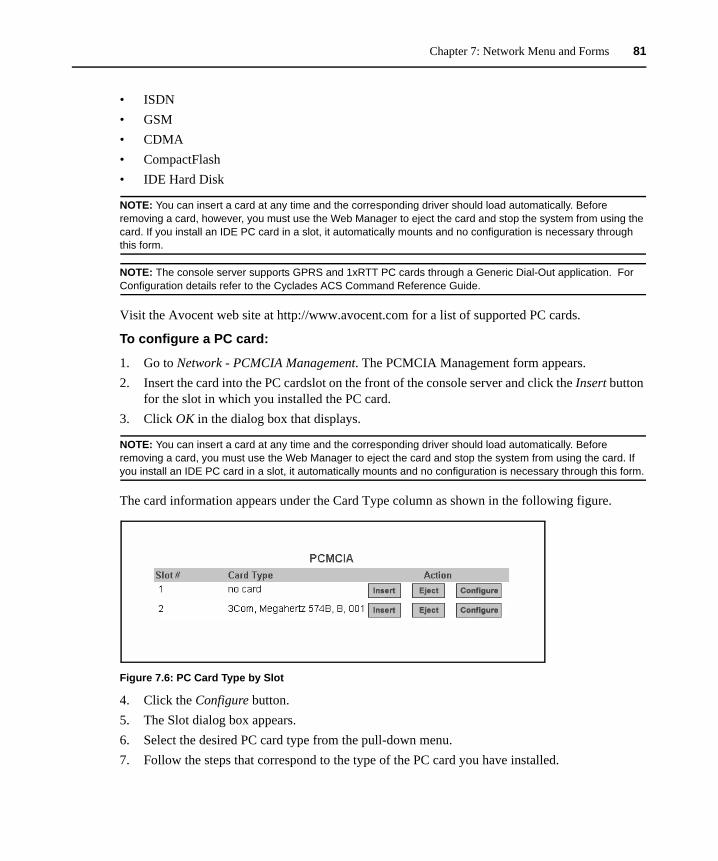
Chapter 7: Network Menu and Forms 81
• ISDN• GSM• CDMA• CompactFlash• IDE Hard Disk
NOTE: You can insert a card at any time and the corresponding driver should load automatically. Before removing a card, however, you must use the Web Manager to eject the card and stop the system from using the card. If you install an IDE PC card in a slot, it automatically mounts and no configuration is necessary through this form.
NOTE: The console server supports GPRS and 1xRTT PC cards through a Generic Dial-Out application. For Configuration details refer to the Cyclades ACS Command Reference Guide.
Visit the Avocent web site at http://www.avocent.com for a list of supported PC cards.
To configure a PC card:
1. Go to Network - PCMCIA Management. The PCMCIA Management form appears.2. Insert the card into the PC cardslot on the front of the console server and click the Insert button
for the slot in which you installed the PC card.3. Click OK in the dialog box that displays.
NOTE: You can insert a card at any time and the corresponding driver should load automatically. Before removing a card, you must use the Web Manager to eject the card and stop the system from using the card. If you install an IDE PC card in a slot, it automatically mounts and no configuration is necessary through this form.
The card information appears under the Card Type column as shown in the following figure.
Figure 7.6: PC Card Type by Slot
4. Click the Configure button.5. The Slot dialog box appears.6. Select the desired PC card type from the pull-down menu.7. Follow the steps that correspond to the type of the PC card you have installed.
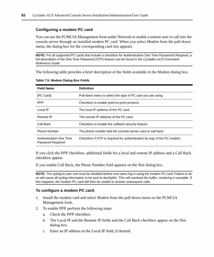
82 Cyclades ACS Advanced Console Server Installation/Administration/User Guide
Configuring a modem PC card
You can use the PCMCIA Management form under Network to enable a remote user to call into the console server through an installed modem PC card. When you select Modem from the pull-down menu, the dialog box for the corresponding card slot appears.
NOTE: For all supported PC cards that include a checkbox for Authentication One Time Passwords Required, a full description of the One Time Password (OTP) feature can be found in the Cyclades ACS Command Reference Guide.
The following table provides a brief description of the fields available in the Modem dialog box.
If you click the PPP checkbox, additional fields for a local and remote IP address and a Call Back checkbox appear.
If you enable Call Back, the Phone Number field appears on the Slot dialog box.
NOTE: The syslog to user root must be disabled before root users log in using the modem PC card. Failure to do so will cause all syslog information to be sent to dev/ttyM1. This will overload the buffer, rendering it unusable. If this happens, the modem PC card will then be unable to answer subsequent calls.
To configure a modem PC card:
1. Install the modem card and select Modem from the pull-down menu on the PCMCIA Management form.
2. To enable PPP, perform the following steps:a. Check the PPP checkbox.b. The Local IP and the Remote IP fields and the Call Back checkbox appear on the Slot
dialog box.c. Enter an IP address in the Local IP field, if desired.
Table 7.5: Modem Dialog Box Fields
Field Name Definition
[PC Card] Pull-down menu to select the type of PC card you are using.
PPP Checkbox to enable point-to-point protocol.
Local IP The local IP address of the PC card.
Remote IP The remote IP address of the PC card.
Call Back Checkbox to enable the callback security feature.
Phone Number The phone number that the console server uses to call back.
Authentication One Time Password Required
Checkbox if OTP is required for authentication by way of the PC modem.
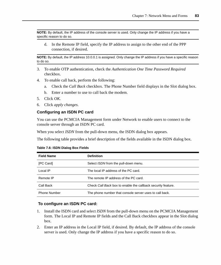
Chapter 7: Network Menu and Forms 83
NOTE: By default, the IP address of the console server is used. Only change the IP address if you have a specific reason to do so.
d. In the Remote IP field, specify the IP address to assign to the other end of the PPP connection, if desired.
NOTE: By default, the IP address 10.0.0.1 is assigned. Only change the IP address if you have a specific reason to do so.
3. To enable OTP authentication, check the Authentication One Time Password Required checkbox.
4. To enable call back, perform the following:a. Check the Call Back checkbox. The Phone Number field displays in the Slot dialog box.b. Enter a number to use to call back the modem.
5. Click OK.6. Click apply changes.
Configuring an ISDN PC card
You can use the PCMCIA Management form under Network to enable users to connect to the console server through an ISDN PC card.
When you select ISDN from the pull-down menu, the ISDN dialog box appears.
The following table provides a brief description of the fields available in the ISDN dialog box.
To configure an ISDN PC card:
1. Install the ISDN card and select ISDN from the pull-down menu on the PCMCIA Management form. The Local IP and Remote IP fields and the Call Back checkbox appear in the Slot dialog box.
2. Enter an IP address in the Local IP field, if desired. By default, the IP address of the console server is used. Only change the IP address if you have a specific reason to do so.
Table 7.6: ISDN Dialog Box Fields
Field Name Definition
[PC Card] Select ISDN from the pull-down menu.
Local IP The local IP address of the PC card.
Remote IP The remote IP address of the PC card.
Call Back Check Call Back box to enable the callback security feature.
Phone Number The phone number that console server uses to call back.
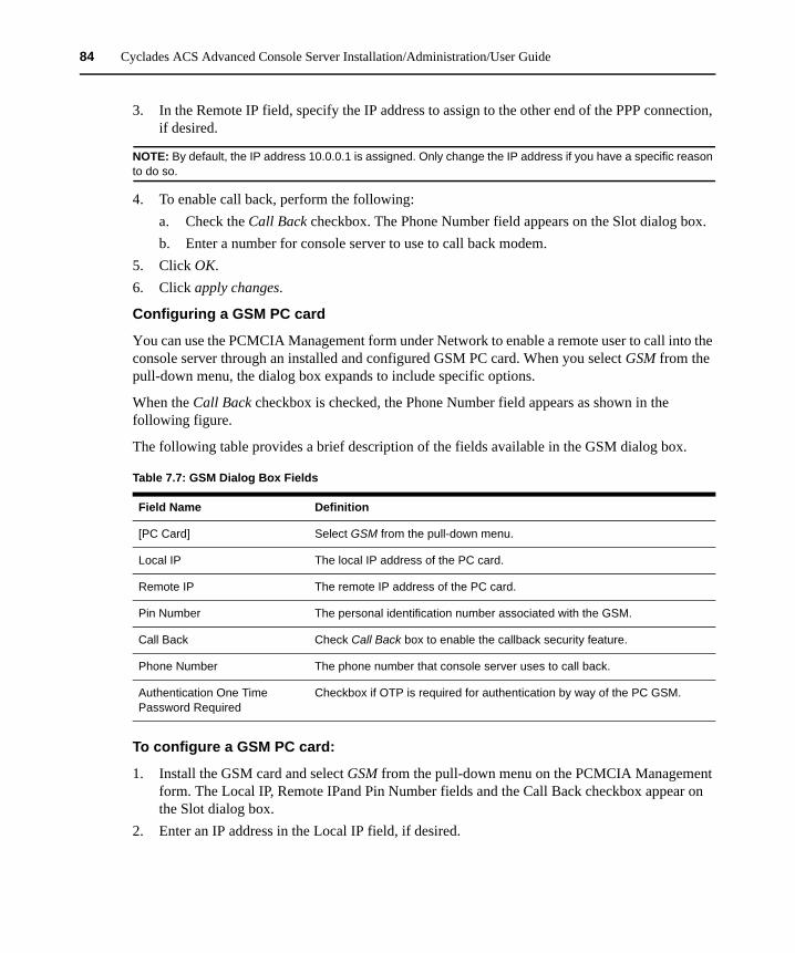
84 Cyclades ACS Advanced Console Server Installation/Administration/User Guide
3. In the Remote IP field, specify the IP address to assign to the other end of the PPP connection, if desired.
NOTE: By default, the IP address 10.0.0.1 is assigned. Only change the IP address if you have a specific reason to do so.
4. To enable call back, perform the following:a. Check the Call Back checkbox. The Phone Number field appears on the Slot dialog box.b. Enter a number for console server to use to call back modem.
5. Click OK.6. Click apply changes.
Configuring a GSM PC card
You can use the PCMCIA Management form under Network to enable a remote user to call into the console server through an installed and configured GSM PC card. When you select GSM from the pull-down menu, the dialog box expands to include specific options.
When the Call Back checkbox is checked, the Phone Number field appears as shown in the following figure.
The following table provides a brief description of the fields available in the GSM dialog box.
To configure a GSM PC card:
1. Install the GSM card and select GSM from the pull-down menu on the PCMCIA Management form. The Local IP, Remote IPand Pin Number fields and the Call Back checkbox appear on the Slot dialog box.
2. Enter an IP address in the Local IP field, if desired.
Table 7.7: GSM Dialog Box Fields
Field Name Definition
[PC Card] Select GSM from the pull-down menu.
Local IP The local IP address of the PC card.
Remote IP The remote IP address of the PC card.
Pin Number The personal identification number associated with the GSM.
Call Back Check Call Back box to enable the callback security feature.
Phone Number The phone number that console server uses to call back.
Authentication One Time Password Required
Checkbox if OTP is required for authentication by way of the PC GSM.
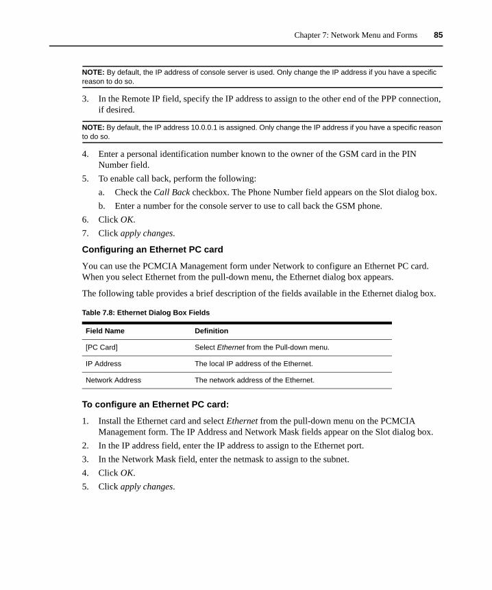
Chapter 7: Network Menu and Forms 85
NOTE: By default, the IP address of console server is used. Only change the IP address if you have a specific reason to do so.
3. In the Remote IP field, specify the IP address to assign to the other end of the PPP connection, if desired.
NOTE: By default, the IP address 10.0.0.1 is assigned. Only change the IP address if you have a specific reason to do so.
4. Enter a personal identification number known to the owner of the GSM card in the PIN Number field.
5. To enable call back, perform the following:a. Check the Call Back checkbox. The Phone Number field appears on the Slot dialog box.b. Enter a number for the console server to use to call back the GSM phone.
6. Click OK.7. Click apply changes.
Configuring an Ethernet PC card
You can use the PCMCIA Management form under Network to configure an Ethernet PC card. When you select Ethernet from the pull-down menu, the Ethernet dialog box appears.
The following table provides a brief description of the fields available in the Ethernet dialog box.
To configure an Ethernet PC card:
1. Install the Ethernet card and select Ethernet from the pull-down menu on the PCMCIA Management form. The IP Address and Network Mask fields appear on the Slot dialog box.
2. In the IP address field, enter the IP address to assign to the Ethernet port.3. In the Network Mask field, enter the netmask to assign to the subnet.4. Click OK.5. Click apply changes.
Table 7.8: Ethernet Dialog Box Fields
Field Name Definition
[PC Card] Select Ethernet from the Pull-down menu.
IP Address The local IP address of the Ethernet.
Network Address The network address of the Ethernet.
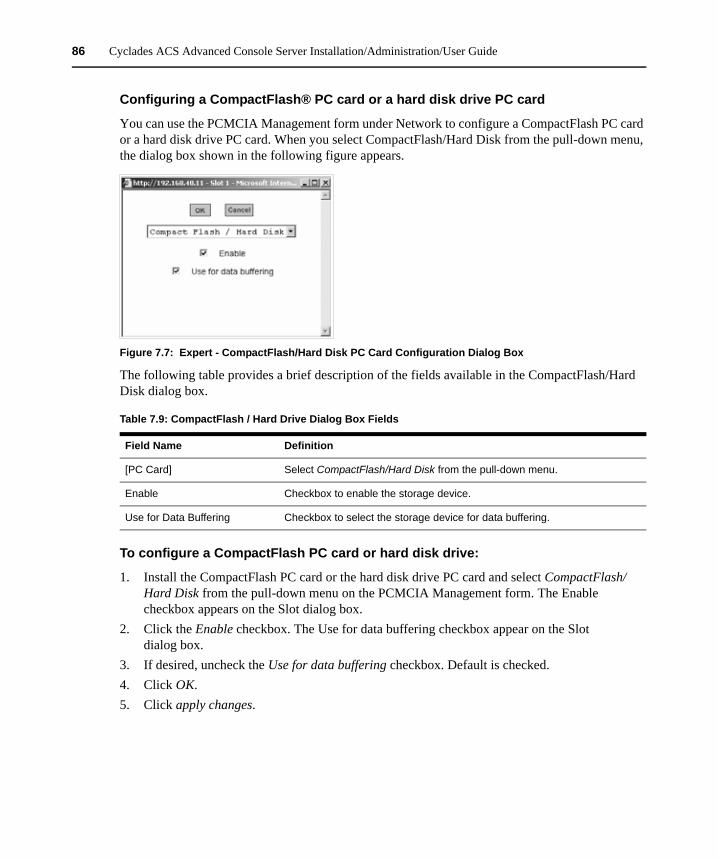
86 Cyclades ACS Advanced Console Server Installation/Administration/User Guide
Configuring a CompactFlash® PC card or a hard disk drive PC card
You can use the PCMCIA Management form under Network to configure a CompactFlash PC card or a hard disk drive PC card. When you select CompactFlash/Hard Disk from the pull-down menu, the dialog box shown in the following figure appears.
Figure 7.7: Expert - CompactFlash/Hard Disk PC Card Configuration Dialog Box
The following table provides a brief description of the fields available in the CompactFlash/Hard Disk dialog box.
To configure a CompactFlash PC card or hard disk drive:
1. Install the CompactFlash PC card or the hard disk drive PC card and select CompactFlash/Hard Disk from the pull-down menu on the PCMCIA Management form. The Enable checkbox appears on the Slot dialog box.
2. Click the Enable checkbox. The Use for data buffering checkbox appear on the Slot dialog box.
3. If desired, uncheck the Use for data buffering checkbox. Default is checked.4. Click OK.5. Click apply changes.
Table 7.9: CompactFlash / Hard Drive Dialog Box Fields
Field Name Definition
[PC Card] Select CompactFlash/Hard Disk from the pull-down menu.
Enable Checkbox to enable the storage device.
Use for Data Buffering Checkbox to select the storage device for data buffering.
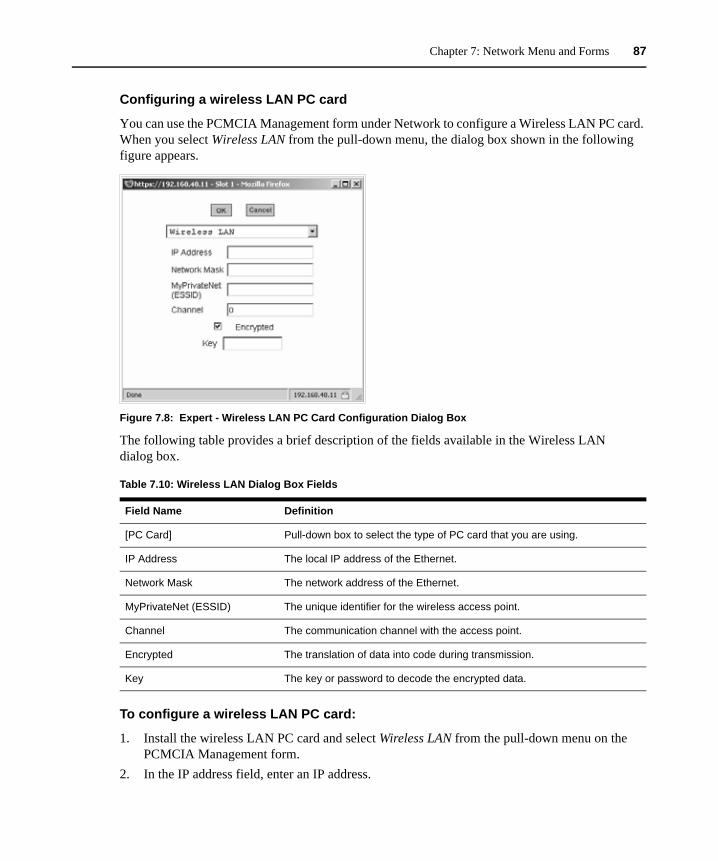
Chapter 7: Network Menu and Forms 87
Configuring a wireless LAN PC card
You can use the PCMCIA Management form under Network to configure a Wireless LAN PC card. When you select Wireless LAN from the pull-down menu, the dialog box shown in the following figure appears.
Figure 7.8: Expert - Wireless LAN PC Card Configuration Dialog Box
The following table provides a brief description of the fields available in the Wireless LAN dialog box.
To configure a wireless LAN PC card:
1. Install the wireless LAN PC card and select Wireless LAN from the pull-down menu on the PCMCIA Management form.
2. In the IP address field, enter an IP address.
Table 7.10: Wireless LAN Dialog Box Fields
Field Name Definition
[PC Card] Pull-down box to select the type of PC card that you are using.
IP Address The local IP address of the Ethernet.
Network Mask The network address of the Ethernet.
MyPrivateNet (ESSID) The unique identifier for the wireless access point.
Channel The communication channel with the access point.
Encrypted The translation of data into code during transmission.
Key The key or password to decode the encrypted data.
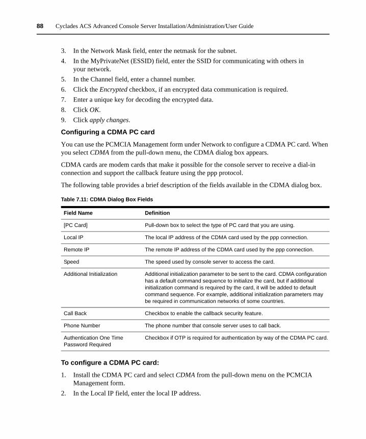
88 Cyclades ACS Advanced Console Server Installation/Administration/User Guide
3. In the Network Mask field, enter the netmask for the subnet.4. In the MyPrivateNet (ESSID) field, enter the SSID for communicating with others in
your network.5. In the Channel field, enter a channel number.6. Click the Encrypted checkbox, if an encrypted data communication is required.7. Enter a unique key for decoding the encrypted data.8. Click OK.9. Click apply changes.
Configuring a CDMA PC card
You can use the PCMCIA Management form under Network to configure a CDMA PC card. When you select CDMA from the pull-down menu, the CDMA dialog box appears.
CDMA cards are modem cards that make it possible for the console server to receive a dial-in connection and support the callback feature using the ppp protocol.
The following table provides a brief description of the fields available in the CDMA dialog box.
To configure a CDMA PC card:
1. Install the CDMA PC card and select CDMA from the pull-down menu on the PCMCIA Management form.
2. In the Local IP field, enter the local IP address.
Table 7.11: CDMA Dialog Box Fields
Field Name Definition
[PC Card] Pull-down box to select the type of PC card that you are using.
Local IP The local IP address of the CDMA card used by the ppp connection.
Remote IP The remote IP address of the CDMA card used by the ppp connection.
Speed The speed used by console server to access the card.
Additional Initialization Additional initialization parameter to be sent to the card. CDMA configuration has a default command sequence to initialize the card, but if additional initialization command is required by the card, it will be added to default command sequence. For example, additional initialization parameters may be required in communication networks of some countries.
Call Back Checkbox to enable the callback security feature.
Phone Number The phone number that console server uses to call back.
Authentication One Time Password Required
Checkbox if OTP is required for authentication by way of the CDMA PC card.
Chapter 7: Network Menu and Forms 89
3. In the Remote IP field, enter the remote IP address.4. From the Speed pull-down menu, select the speed defined by the specifications of the CDMA
PC card you are using.5. In the Additional Initialization field, enter additional parameters if required by the card. 6. To enable call back, perform the following:
a. Check the Call Back checkbox. The Phone Number field appears on the Slot dialog box.b. Enter a number for the console server to use to call back the CDMA PC card.
7. Click OK.8. Click apply changes.
Ejecting a PC card
Use the Eject button on the PCMCIA management form to eject any PC card before physically ejecting it.
CAUTION: Always use the Eject button to eject the PC card. Any other method can cause a kernel panic.
To eject a PC card:
1. Go to Network - PCMCIA Management. The PCMCIA Management form appears.2. Click the Eject button adjacent to the card you wish to remove. The card type clears under the
Card Type column.3. Click apply changes.4. Remove the PC card from the card slot.
VPN ConnectionsVirtual Private Network (VPN) enables a secured communication between the console server and a remote network by utilizing a gateway and creating a secured connection between the console server and the gateway. IPSec is the protocol used to construct the secure tunnel. IPSec provides encryption and authentication services at the IP level of the protocol stack.
When VPN Connections is selected under Network, the VPN Connections form appears.
You can use the form to add a VPN connection or edit one already in the list. When you click the Edit or Add buttons, a New/Modify Connection form appears, as shown in the following figure. The form displays different fields depending on whether RSA Public Keys or Shared Secret is selected.
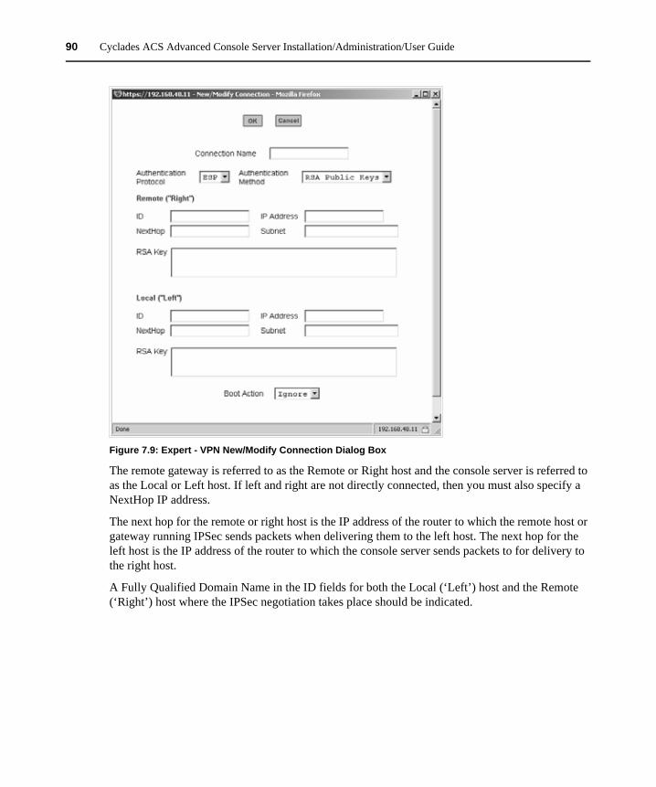
90 Cyclades ACS Advanced Console Server Installation/Administration/User Guide
Figure 7.9: Expert - VPN New/Modify Connection Dialog Box
The remote gateway is referred to as the Remote or Right host and the console server is referred to as the Local or Left host. If left and right are not directly connected, then you must also specify a NextHop IP address.
The next hop for the remote or right host is the IP address of the router to which the remote host or gateway running IPSec sends packets when delivering them to the left host. The next hop for the left host is the IP address of the router to which the console server sends packets to for delivery to the right host.
A Fully Qualified Domain Name in the ID fields for both the Local (‘Left’) host and the Remote (‘Right’) host where the IPSec negotiation takes place should be indicated.
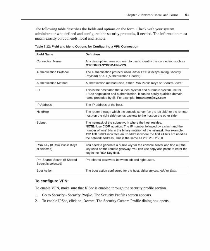
Chapter 7: Network Menu and Forms 91
The following table describes the fields and options on the form. Check with your system administrator who defined and configured the security protocols, if needed. The information must match exactly on both ends, local and remote.
To configure VPN:
To enable VPN, make sure that IPSec is enabled through the security profile section.
1. Go to Security - Security Profile. The Security Profiles screen appears.2. To enable IPSec, click on Custom. The Security Custom Profile dialog box opens.
Table 7.12: Field and Menu Options for Configuring a VPN Connection
Field Name Definition
Connection Name Any descriptive name you wish to use to identify this connection such as MYCOMPANYDOMAIN-VPN.
Authentication Protocol The authentication protocol used, either ESP (Encapsulating Security Payload) or AH (Authentication Header).
Authentication Method Authentication method used, either RSA Public Keys or Shared Secret.
ID This is the hostname that a local system and a remote system use for IPSec negotiation and authentication. It can be a fully qualified domain name preceded by @. For example, [email protected]
IP Address The IP address of the host.
NextHop The router through which the console server (on the left side) or the remote host (on the right side) sends packets to the host on the other side.
Subnet The netmask of the subnetwork where the host resides.NOTE: Use CIDR notation. The IP number followed by a slash and the number of ‘one’ bits in the binary notation of the netmask. For example, 192.168.0.0/24 indicates an IP address where the first 24 bits are used as the network address. This is the same as 255.255.255.0.
RSA Key (If RSA Public Keys is selected)
You need to generate a public key for the console server and find out the key used on the remote gateway. You can use copy and paste to enter the key in the RSA Key field.
Pre-Shared Secret (If Shared Secret is selected)
Pre-shared password between left and right users.
Boot Action The boot action configured for the host, either Ignore, Add or Start.
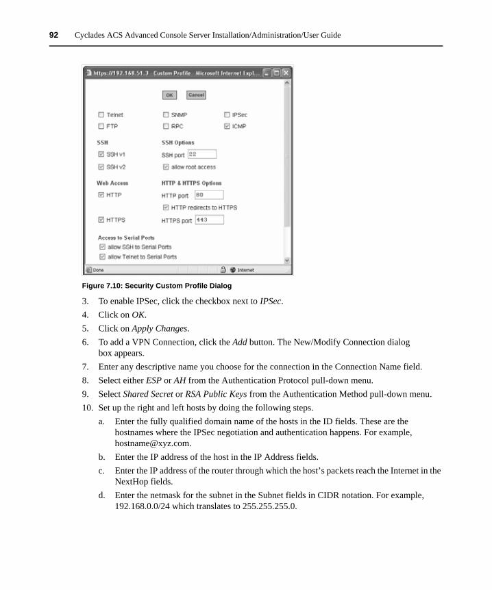
92 Cyclades ACS Advanced Console Server Installation/Administration/User Guide
Figure 7.10: Security Custom Profile Dialog
3. To enable IPSec, click the checkbox next to IPSec.4. Click on OK.5. Click on Apply Changes.6. To add a VPN Connection, click the Add button. The New/Modify Connection dialog
box appears.7. Enter any descriptive name you choose for the connection in the Connection Name field.8. Select either ESP or AH from the Authentication Protocol pull-down menu.9. Select Shared Secret or RSA Public Keys from the Authentication Method pull-down menu.10. Set up the right and left hosts by doing the following steps.
a. Enter the fully qualified domain name of the hosts in the ID fields. These are the hostnames where the IPSec negotiation and authentication happens. For example, [email protected].
b. Enter the IP address of the host in the IP Address fields.c. Enter the IP address of the router through which the host’s packets reach the Internet in the
NextHop fields.d. Enter the netmask for the subnet in the Subnet fields in CIDR notation. For example,
192.168.0.0/24 which translates to 255.255.255.0.
Chapter 7: Network Menu and Forms 93
e. If RSA Key is selected, generate the key for the console server (left host) and find out the key from the remote gateway (right host). You can use copy and paste to enter the key in the RSA Key field.
f. If Shared Secret is selected, enter the shared secret in the Pre-Shared Secret field.11. Select either Ignore, Add or Start from the Boot Action pull-down menu.12. Click OK.13. Click apply changes.
SNMPSimple Network Management Protocol (SNMP) is a set of protocols for managing complex networks. SNMP works by sending messages called protocol data units (PDUs) to different parts of a network. SNMP-compliant devices (agents), store data about themselves in Management Information Bases (MIBs) and return this data to the SNMP requesters.
The console server’s SNMP agent supports SNMPv1/v2 and v3. To use SNMP v1 or v2, you need to specify a community name, a source IP address or a range of IP addresses, an object ID (OID) and permission (read-write or read-only). SNMP v3 requires: username, password, OID and permission.
Selecting Network - SNMP displays the form shown in the following figure.
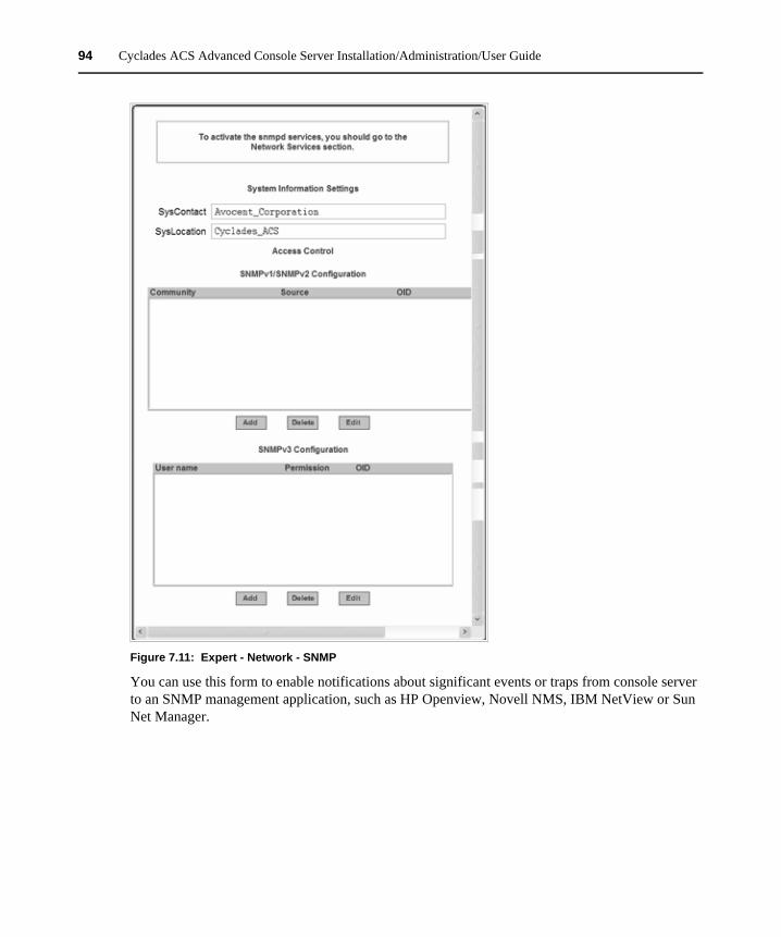
94 Cyclades ACS Advanced Console Server Installation/Administration/User Guide
Figure 7.11: Expert - Network - SNMP
You can use this form to enable notifications about significant events or traps from console server to an SNMP management application, such as HP Openview, Novell NMS, IBM NetView or Sun Net Manager.
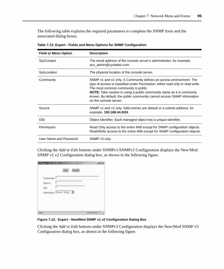
Chapter 7: Network Menu and Forms 95
The following table explains the required parameters to complete the SNMP form and the associated dialog boxes.
Clicking the Add or Edit buttons under SNMPv1/SNMPv2 Configuration displays the New/Mod SNMP v1 v2 Configuration dialog box, as shown in the following figure.
Figure 7.12: Expert - New/Mod SNMP v1 v2 Configuration Dialog Box
Clicking the Add or Edit buttons under SNMPv3 Configuration displays the New/Mod SNMP v3 Configuration dialog box, as shown in the following figure.
Table 7.13: Expert - Fields and Menu Options for SNMP Configuration
Field or Menu Option Description
SysContact The email address of the console server’s administrator, for example, [email protected].
SysLocation The physical location of the console server.
Community SNMP v1 and v2 only. A Community defines an access environment. The type of access is classified under Permission: either read only or read write. The most common community is public.NOTE: Take caution in using a public community name as it is commonly known. By default, the public community cannot access SNMP information on the console server.
Source SNMP v1 and v2 only. Valid entries are default or a subnet address, for example, 193.168.44.0/24.
OID Object Identifier. Each managed object has a unique identifier.
Permission Read Only access to the entire MIB except for SNMP configuration objects.Read/Write access to the entire MIB except for SNMP configuration objects.
User Name and Password SNMP v3 only.
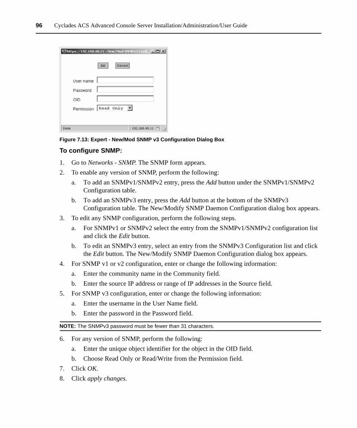
96 Cyclades ACS Advanced Console Server Installation/Administration/User Guide
Figure 7.13: Expert - New/Mod SNMP v3 Configuration Dialog Box
To configure SNMP:
1. Go to Networks - SNMP. The SNMP form appears. 2. To enable any version of SNMP, perform the following:
a. To add an SNMPv1/SNMPv2 entry, press the Add button under the SNMPv1/SNMPv2 Configuration table.
b. To add an SNMPv3 entry, press the Add button at the bottom of the SNMPv3 Configuration table. The New/Modify SNMP Daemon Configuration dialog box appears.
3. To edit any SNMP configuration, perform the following steps.a. For SNMPv1 or SNMPv2 select the entry from the SNMPv1/SNMPv2 configuration list
and click the Edit button.b. To edit an SNMPv3 entry, select an entry from the SNMPv3 Configuration list and click
the Edit button. The New/Modify SNMP Daemon Configuration dialog box appears.4. For SNMP v1 or v2 configuration, enter or change the following information:
a. Enter the community name in the Community field.b. Enter the source IP address or range of IP addresses in the Source field.
5. For SNMP v3 configuration, enter or change the following information:a. Enter the username in the User Name field.b. Enter the password in the Password field.
NOTE: The SNMPv3 password must be fewer than 31 characters.
6. For any version of SNMP, perform the following:a. Enter the unique object identifier for the object in the OID field.b. Choose Read Only or Read/Write from the Permission field.
7. Click OK. 8. Click apply changes.
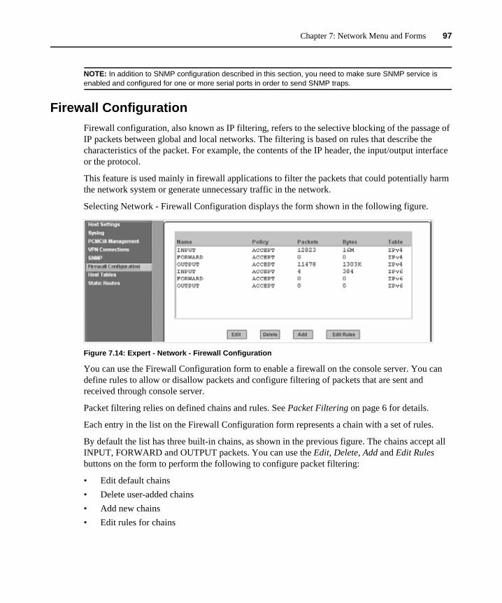
Chapter 7: Network Menu and Forms 97
NOTE: In addition to SNMP configuration described in this section, you need to make sure SNMP service is enabled and configured for one or more serial ports in order to send SNMP traps.
Firewall ConfigurationFirewall configuration, also known as IP filtering, refers to the selective blocking of the passage of IP packets between global and local networks. The filtering is based on rules that describe the characteristics of the packet. For example, the contents of the IP header, the input/output interface or the protocol.
This feature is used mainly in firewall applications to filter the packets that could potentially harm the network system or generate unnecessary traffic in the network.
Selecting Network - Firewall Configuration displays the form shown in the following figure.
Figure 7.14: Expert - Network - Firewall Configuration
You can use the Firewall Configuration form to enable a firewall on the console server. You can define rules to allow or disallow packets and configure filtering of packets that are sent and received through console server.
Packet filtering relies on defined chains and rules. See Packet Filtering on page 6 for details.
Each entry in the list on the Firewall Configuration form represents a chain with a set of rules.
By default the list has three built-in chains, as shown in the previous figure. The chains accept all INPUT, FORWARD and OUTPUT packets. You can use the Edit, Delete, Add and Edit Rules buttons on the form to perform the following to configure packet filtering:
• Edit default chains• Delete user-added chains• Add new chains• Edit rules for chains
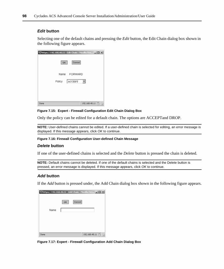
98 Cyclades ACS Advanced Console Server Installation/Administration/User Guide
Edit button
Selecting one of the default chains and pressing the Edit button, the Edit Chain dialog box shown in the following figure appears.
Figure 7.15: Expert - Firewall Configuration Edit Chain Dialog Box
Only the policy can be edited for a default chain. The options are ACCEPTand DROP.
NOTE: User-defined chains cannot be edited. If a user-defined chain is selected for editing, an error message is displayed. If this message appears, click OK to continue.
Figure 7.16: Firewall Configuration User-defined Chain Message
Delete button
If one of the user-defined chains is selected and the Delete button is pressed the chain is deleted.
NOTE: Default chains cannot be deleted. If one of the default chains is selected and the Delete button is pressed, an error message is displayed. If this message appears, click OK to continue.
Add button
If the Add button is pressed under, the Add Chain dialog box shown in the following figure appears.
Figure 7.17: Expert - Firewall Configuration Add Chain Dialog Box
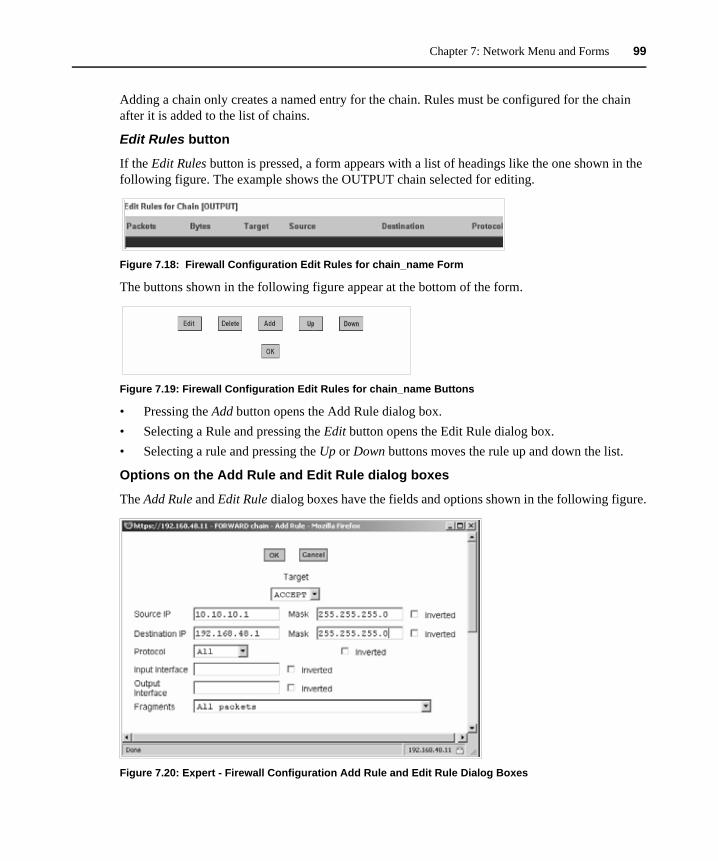
Chapter 7: Network Menu and Forms 99
Adding a chain only creates a named entry for the chain. Rules must be configured for the chain after it is added to the list of chains.
Edit Rules button
If the Edit Rules button is pressed, a form appears with a list of headings like the one shown in the following figure. The example shows the OUTPUT chain selected for editing.
Figure 7.18: Firewall Configuration Edit Rules for chain_name Form
The buttons shown in the following figure appear at the bottom of the form.
Figure 7.19: Firewall Configuration Edit Rules for chain_name Buttons
• Pressing the Add button opens the Add Rule dialog box.• Selecting a Rule and pressing the Edit button opens the Edit Rule dialog box. • Selecting a rule and pressing the Up or Down buttons moves the rule up and down the list.
Options on the Add Rule and Edit Rule dialog boxes
The Add Rule and Edit Rule dialog boxes have the fields and options shown in the following figure.
Figure 7.20: Expert - Firewall Configuration Add Rule and Edit Rule Dialog Boxes
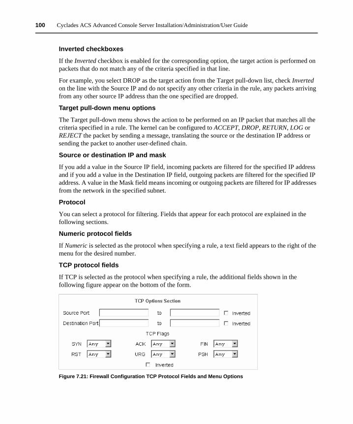
100 Cyclades ACS Advanced Console Server Installation/Administration/User Guide
Inverted checkboxes
If the Inverted checkbox is enabled for the corresponding option, the target action is performed on packets that do not match any of the criteria specified in that line.
For example, you select DROP as the target action from the Target pull-down list, check Inverted on the line with the Source IP and do not specify any other criteria in the rule, any packets arriving from any other source IP address than the one specified are dropped.
Target pull-down menu options
The Target pull-down menu shows the action to be performed on an IP packet that matches all the criteria specified in a rule. The kernel can be configured to ACCEPT, DROP, RETURN, LOG or REJECT the packet by sending a message, translating the source or the destination IP address or sending the packet to another user-defined chain.
Source or destination IP and mask
If you add a value in the Source IP field, incoming packets are filtered for the specified IP address and if you add a value in the Destination IP field, outgoing packets are filtered for the specified IP address. A value in the Mask field means incoming or outgoing packets are filtered for IP addresses from the network in the specified subnet.
Protocol
You can select a protocol for filtering. Fields that appear for each protocol are explained in the following sections.
Numeric protocol fields
If Numeric is selected as the protocol when specifying a rule, a text field appears to the right of the menu for the desired number.
TCP protocol fields
If TCP is selected as the protocol when specifying a rule, the additional fields shown in the following figure appear on the bottom of the form.
Figure 7.21: Firewall Configuration TCP Protocol Fields and Menu Options
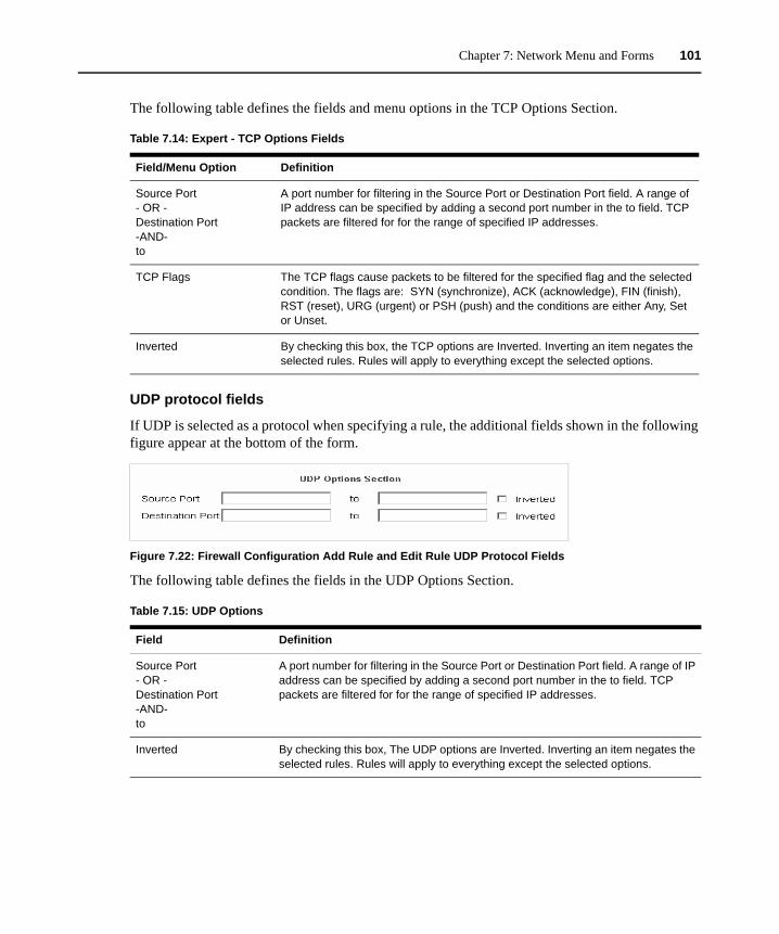
Chapter 7: Network Menu and Forms 101
The following table defines the fields and menu options in the TCP Options Section.
UDP protocol fields
If UDP is selected as a protocol when specifying a rule, the additional fields shown in the following figure appear at the bottom of the form.
Figure 7.22: Firewall Configuration Add Rule and Edit Rule UDP Protocol Fields
The following table defines the fields in the UDP Options Section.
Table 7.14: Expert - TCP Options Fields
Field/Menu Option Definition
Source Port - OR - Destination Port -AND- to
A port number for filtering in the Source Port or Destination Port field. A range of IP address can be specified by adding a second port number in the to field. TCP packets are filtered for for the range of specified IP addresses.
TCP Flags The TCP flags cause packets to be filtered for the specified flag and the selected condition. The flags are: SYN (synchronize), ACK (acknowledge), FIN (finish), RST (reset), URG (urgent) or PSH (push) and the conditions are either Any, Set or Unset.
Inverted By checking this box, the TCP options are Inverted. Inverting an item negates the selected rules. Rules will apply to everything except the selected options.
Table 7.15: UDP Options
Field Definition
Source Port - OR - Destination Port -AND- to
A port number for filtering in the Source Port or Destination Port field. A range of IP address can be specified by adding a second port number in the to field. TCP packets are filtered for for the range of specified IP addresses.
Inverted By checking this box, The UDP options are Inverted. Inverting an item negates the selected rules. Rules will apply to everything except the selected options.
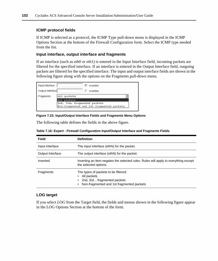
102 Cyclades ACS Advanced Console Server Installation/Administration/User Guide
ICMP protocol fields
If ICMP is selected as a protocol, the ICMP Type pull-down menu is displayed in the ICMP Options Section at the bottom of the Firewall Configuration form. Select the ICMP type needed from the list.
Input interface, output interface and fragments
If an interface (such as eth0 or eth1) is entered in the Input Interface field, incoming packets are filtered for the specified interface. If an interface is entered in the Output Interface field, outgoing packets are filtered for the specified interface. The input and output interface fields are shown in the following figure along with the options on the Fragments pull-down menu.
Figure 7.23: Input/Output Interface Fields and Fragments Menu Options
The following table defines the fields in the above figure.
LOG target
If you select LOG from the Target field, the fields and menus shown in the following figure appear in the LOG Options Section at the bottom of the form.
Table 7.16: Expert - Firewall Configuration Input/Output Interface and Fragments Fields
Field Definition
Input Interface The input interface (ethN) for the packet.
Output Interface The output interface (ethN) for the packet.
Inverted Inverting an item negates the selected rules. Rules will apply to everything except the selected options.
Fragments The types of packets to be filtered: • All packets• 2nd, 3rd... fragmented packets• Non-fragmented and 1st fragmented packets
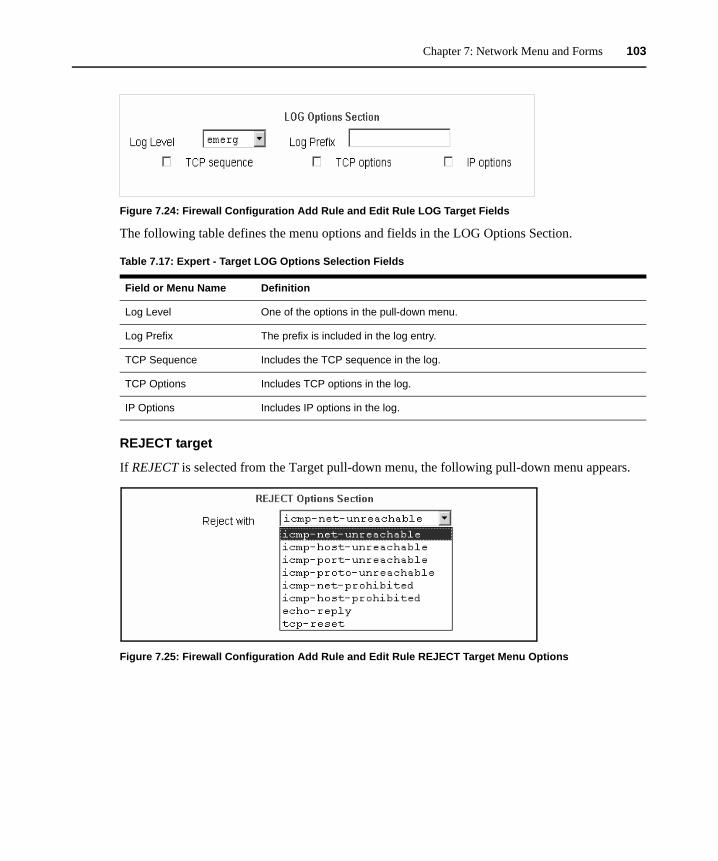
Chapter 7: Network Menu and Forms 103
Figure 7.24: Firewall Configuration Add Rule and Edit Rule LOG Target Fields
The following table defines the menu options and fields in the LOG Options Section.
REJECT target
If REJECT is selected from the Target pull-down menu, the following pull-down menu appears.
Figure 7.25: Firewall Configuration Add Rule and Edit Rule REJECT Target Menu Options
Table 7.17: Expert - Target LOG Options Selection Fields
Field or Menu Name Definition
Log Level One of the options in the pull-down menu.
Log Prefix The prefix is included in the log entry.
TCP Sequence Includes the TCP sequence in the log.
TCP Options Includes TCP options in the log.
IP Options Includes IP options in the log.
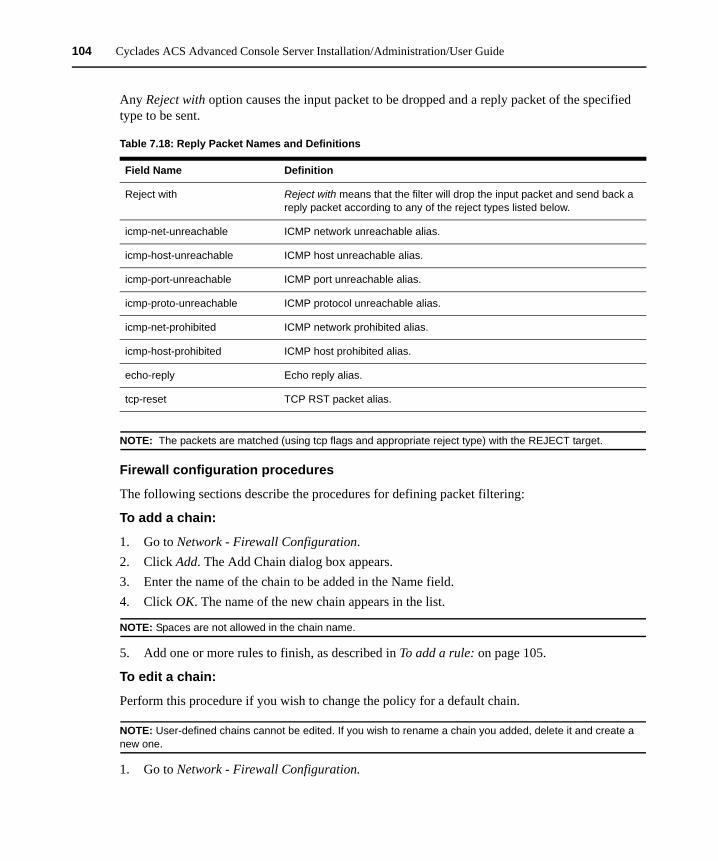
104 Cyclades ACS Advanced Console Server Installation/Administration/User Guide
Any Reject with option causes the input packet to be dropped and a reply packet of the specified type to be sent.
NOTE: The packets are matched (using tcp flags and appropriate reject type) with the REJECT target.
Firewall configuration procedures
The following sections describe the procedures for defining packet filtering:
To add a chain:
1. Go to Network - Firewall Configuration.2. Click Add. The Add Chain dialog box appears.3. Enter the name of the chain to be added in the Name field.4. Click OK. The name of the new chain appears in the list.
NOTE: Spaces are not allowed in the chain name.
5. Add one or more rules to finish, as described in To add a rule: on page 105.
To edit a chain:
Perform this procedure if you wish to change the policy for a default chain.
NOTE: User-defined chains cannot be edited. If you wish to rename a chain you added, delete it and create a new one.
1. Go to Network - Firewall Configuration.
Table 7.18: Reply Packet Names and Definitions
Field Name Definition
Reject with Reject with means that the filter will drop the input packet and send back a reply packet according to any of the reject types listed below.
icmp-net-unreachable ICMP network unreachable alias.
icmp-host-unreachable ICMP host unreachable alias.
icmp-port-unreachable ICMP port unreachable alias.
icmp-proto-unreachable ICMP protocol unreachable alias.
icmp-net-prohibited ICMP network prohibited alias.
icmp-host-prohibited ICMP host prohibited alias.
echo-reply Echo reply alias.
tcp-reset TCP RST packet alias.
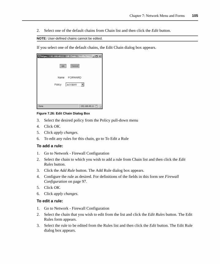
Chapter 7: Network Menu and Forms 105
2. Select one of the default chains from Chain list and then click the Edit button.
NOTE: User-defined chains cannot be edited.
If you select one of the default chains, the Edit Chain dialog box appears.
Figure 7.26: Edit Chain Dialog Box
3. Select the desired policy from the Policy pull-down menu4. Click OK.5. Click apply changes.6. To edit any rules for this chain, go to To Edit a Rule
To add a rule:
1. Go to Network - Firewall Configuration2. Select the chain to which you wish to add a rule from Chain list and then click the Edit
Rules button.3. Click the Add Rule button. The Add Rule dialog box appears. 4. Configure the rule as desired. For definitions of the fields in this form see Firewall
Configuration on page 97.5. Click OK.6. Click apply changes.
To edit a rule:
1. Go to Network - Firewall Configuration2. Select the chain that you wish to edit from the list and click the Edit Rules button. The Edit
Rules form appears. 3. Select the rule to be edited from the Rules list and then click the Edit button. The Edit Rule
dialog box appears.
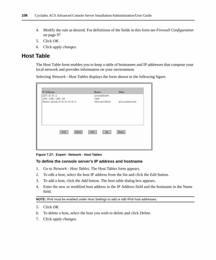
106 Cyclades ACS Advanced Console Server Installation/Administration/User Guide
4. Modify the rule as desired. For definitions of the fields in this form see Firewall Configuration on page 97
5. Click OK.6. Click apply changes.
Host TableThe Host Table form enables you to keep a table of hostnames and IP addresses that compose your local network and provides information on your environment.
Selecting Network - Host Tables displays the form shown in the following figure.
Figure 7.27: Expert - Network - Host Tables
To define the console server’s IP address and hostname
1. Go to Network - Host Tables. The Host Tables form appears.2. To edit a host, select the host IP address from the list and click the Edit button.3. To add a host, click the Add button. The host table dialog box appears.4. Enter the new or modified host address in the IP Address field and the hostname in the Name
field.
NOTE: IPv6 must be enabled under Host Settings to add or edit IPv6 host addresses.
5. Click OK.6. To delete a host, select the host you wish to delete and click Delete.7. Click apply changes.
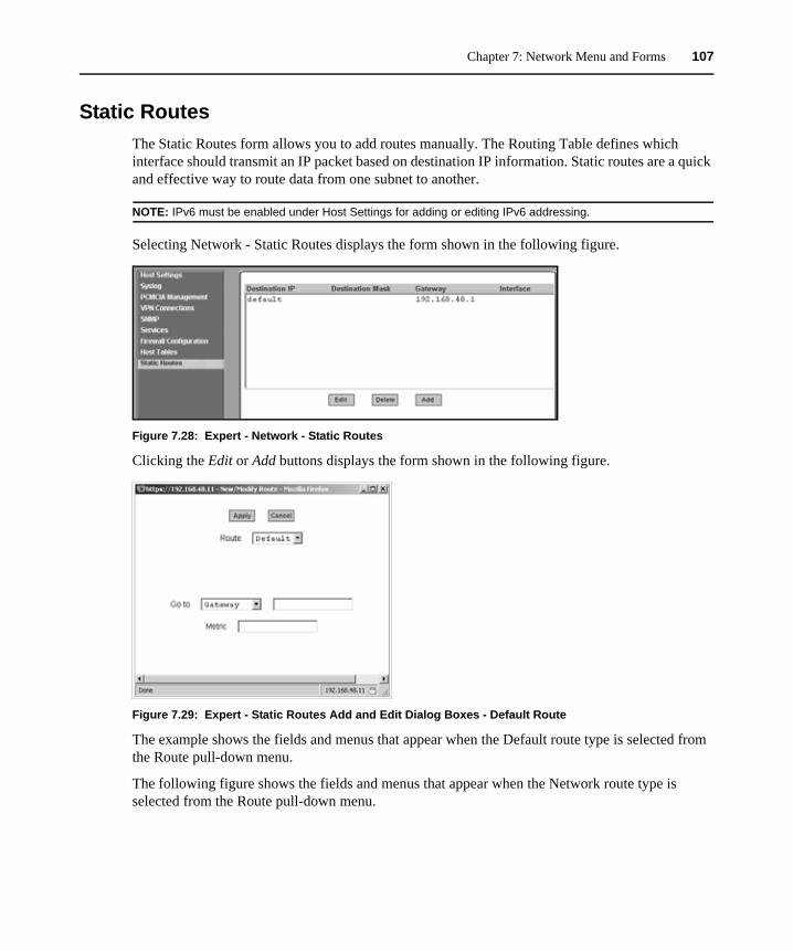
Chapter 7: Network Menu and Forms 107
Static RoutesThe Static Routes form allows you to add routes manually. The Routing Table defines which interface should transmit an IP packet based on destination IP information. Static routes are a quick and effective way to route data from one subnet to another.
NOTE: IPv6 must be enabled under Host Settings for adding or editing IPv6 addressing.
Selecting Network - Static Routes displays the form shown in the following figure.
Figure 7.28: Expert - Network - Static Routes
Clicking the Edit or Add buttons displays the form shown in the following figure.
Figure 7.29: Expert - Static Routes Add and Edit Dialog Boxes - Default Route
The example shows the fields and menus that appear when the Default route type is selected from the Route pull-down menu.
The following figure shows the fields and menus that appear when the Network route type is selected from the Route pull-down menu.
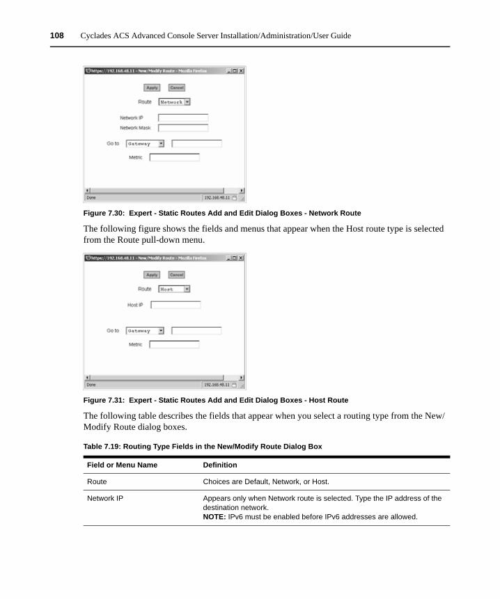
108 Cyclades ACS Advanced Console Server Installation/Administration/User Guide
Figure 7.30: Expert - Static Routes Add and Edit Dialog Boxes - Network Route
The following figure shows the fields and menus that appear when the Host route type is selected from the Route pull-down menu.
Figure 7.31: Expert - Static Routes Add and Edit Dialog Boxes - Host Route
The following table describes the fields that appear when you select a routing type from the New/Modify Route dialog boxes.
Table 7.19: Routing Type Fields in the New/Modify Route Dialog Box
Field or Menu Name Definition
Route Choices are Default, Network, or Host.
Network IP Appears only when Network route is selected. Type the IP address of the destination network.NOTE: IPv6 must be enabled before IPv6 addresses are allowed.
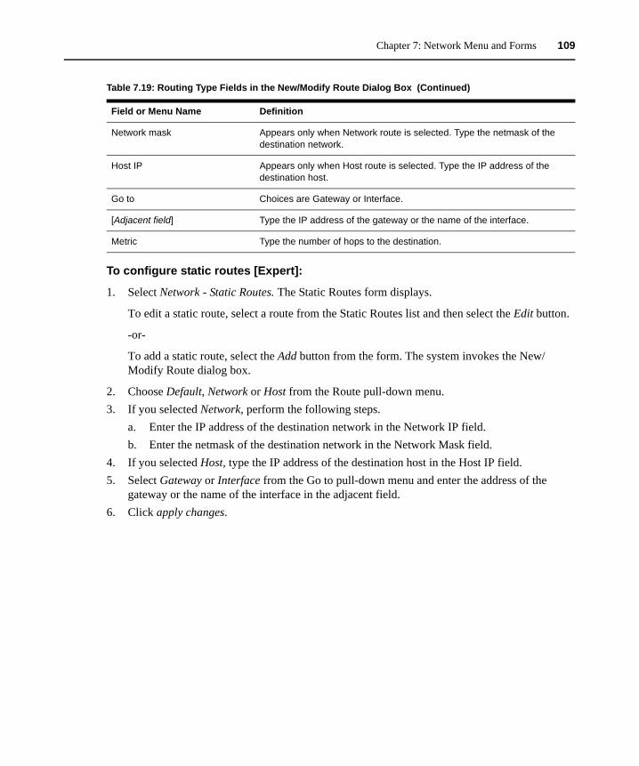
Chapter 7: Network Menu and Forms 109
To configure static routes [Expert]:
1. Select Network - Static Routes. The Static Routes form displays.
To edit a static route, select a route from the Static Routes list and then select the Edit button.
-or-
To add a static route, select the Add button from the form. The system invokes the New/Modify Route dialog box.
2. Choose Default, Network or Host from the Route pull-down menu. 3. If you selected Network, perform the following steps.
a. Enter the IP address of the destination network in the Network IP field.b. Enter the netmask of the destination network in the Network Mask field.
4. If you selected Host, type the IP address of the destination host in the Host IP field.5. Select Gateway or Interface from the Go to pull-down menu and enter the address of the
gateway or the name of the interface in the adjacent field.6. Click apply changes.
Network mask Appears only when Network route is selected. Type the netmask of the destination network.
Host IP Appears only when Host route is selected. Type the IP address of the destination host.
Go to Choices are Gateway or Interface.
[Adjacent field] Type the IP address of the gateway or the name of the interface.
Metric Type the number of hops to the destination.
Table 7.19: Routing Type Fields in the New/Modify Route Dialog Box (Continued)
Field or Menu Name Definition

110 Cyclades ACS Advanced Console Server Installation/Administration/User Guide
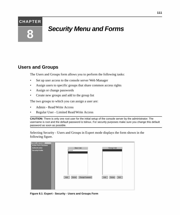
111
CHAPTER
8 Security Menu and Forms
Users and GroupsThe Users and Groups form allows you to perform the following tasks:
• Set up user access to the console server Web Manager• Assign users to specific groups that share common access rights• Assign or change passwords• Create new groups and add to the group list
The two groups to which you can assign a user are:
• Admin - Read/Write Access• Regular User - Limited Read/Write Access
CAUTION: There is only one root user for the initial setup of the console server by the administrator. The username is root and the default password is tslinux. For security purposes make sure you change this default password as soon as possible.
Selecting Security - Users and Groups in Expert mode displays the form shown in the following figure.
Figure 8.1: Expert - Security - Users and Groups Form
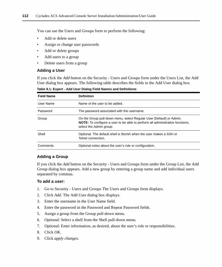
112 Cyclades ACS Advanced Console Server Installation/Administration/User Guide
You can use the Users and Groups form to perform the following:
• Add or delete users• Assign or change user passwords• Add or delete groups• Add users to a group• Delete users from a group
Adding a User
If you click the Add button on the Security - Users and Groups form under the Users List, the Add User dialog box appears. The following table describes the fields in the Add User dialog box.
Adding a Group
If you click the Add button on the Security - Users and Groups form under the Group List, the Add Group dialog box appears. Add a new group by entering a group name and add individual users separated by commas.
To add a user:
1. Go to Security - Users and Groups The Users and Groups form displays.2. Click Add. The Add User dialog box displays.3. Enter the username in the User Name field.4. Enter the password in the Password and Repeat Password fields.5. Assign a group from the Group pull-down menu.6. Optional: Select a shell from the Shell pull-down menu.7. Optional: Enter information, as desired, about the user’s role or responsibilities. 8. Click OK. 9. Click apply changes.
Table 8.1: Expert - Add User Dialog Field Names and Definitions
Field Name Definition
User Name Name of the user to be added.
Password The password associated with the username.
Group On the Group pull-down menu, select Regular User [Default] or Admin. NOTE: To configure a user to be able to perform all administrative functions, select the Admin group.
Shell Optional. The default shell is /bin/sh when the user makes a SSH or Telnet connection.
Comments Optional notes about the user’s role or configuration.

Chapter 8: Security Menu and Forms 113
To delete a user or group:
1. Go to Security - Users and Groups. The Users and Groups form displays.2. Select the name of a user or group to delete.3. Click Delete.4. Click apply changes.
To change a user’s password:
1. Go to Security - Users and Groups. The Users and Groups form displays.2. Select the name of the user whose password you wish to change.3. Click Change Password. The Change User Password dialog box displays.4. Enter the new password in the New Password field and enter it again in the Repeat New
Password field.5. Click OK.6. Click apply changes.
To add a group:
1. Go to Security - Users and Groups. The Users and Groups form displays.2. Under the list of groups, click Add. The Add Group dialog box displays.3. Enter the name for the new group in the Group Name field.4. Enter one username or multiple comma-separated usernames in the Users field.5. Click OK.6. Click apply changes.
To modify a group:
1. Go to Security - Users and Groups. The Users and Groups form displays.2. Select the name of a group to modify.3. Click Edit. The Edit Group form displays.4. Add or delete users from the group as desired.5. Click OK.6. Click apply changes.
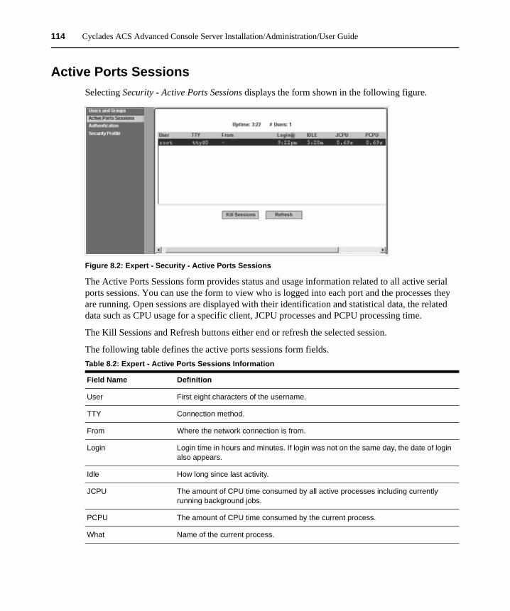
114 Cyclades ACS Advanced Console Server Installation/Administration/User Guide
Active Ports Sessions Selecting Security - Active Ports Sessions displays the form shown in the following figure.
Figure 8.2: Expert - Security - Active Ports Sessions
The Active Ports Sessions form provides status and usage information related to all active serial ports sessions. You can use the form to view who is logged into each port and the processes they are running. Open sessions are displayed with their identification and statistical data, the related data such as CPU usage for a specific client, JCPU processes and PCPU processing time.
The Kill Sessions and Refresh buttons either end or refresh the selected session.
The following table defines the active ports sessions form fields.Table 8.2: Expert - Active Ports Sessions Information
Field Name Definition
User First eight characters of the username.
TTY Connection method.
From Where the network connection is from.
Login Login time in hours and minutes. If login was not on the same day, the date of login also appears.
Idle How long since last activity.
JCPU The amount of CPU time consumed by all active processes including currently running background jobs.
PCPU The amount of CPU time consumed by the current process.
What Name of the current process.
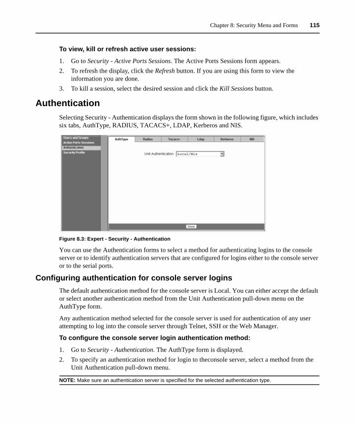
Chapter 8: Security Menu and Forms 115
To view, kill or refresh active user sessions:
1. Go to Security - Active Ports Sessions. The Active Ports Sessions form appears. 2. To refresh the display, click the Refresh button. If you are using this form to view the
information you are done.3. To kill a session, select the desired session and click the Kill Sessions button.
AuthenticationSelecting Security - Authentication displays the form shown in the following figure, which includes six tabs, AuthType, RADIUS, TACACS+, LDAP, Kerberos and NIS.
Figure 8.3: Expert - Security - Authentication
You can use the Authentication forms to select a method for authenticating logins to the console server or to identify authentication servers that are configured for logins either to the console server or to the serial ports.
Configuring authentication for console server loginsThe default authentication method for the console server is Local. You can either accept the default or select another authentication method from the Unit Authentication pull-down menu on the AuthType form.
Any authentication method selected for the console server is used for authentication of any user attempting to log into the console server through Telnet, SSH or the Web Manager.
To configure the console server login authentication method:
1. Go to Security - Authentication. The AuthType form is displayed.2. To specify an authentication method for login to theconsole server, select a method from the
Unit Authentication pull-down menu.
NOTE: Make sure an authentication server is specified for the selected authentication type.
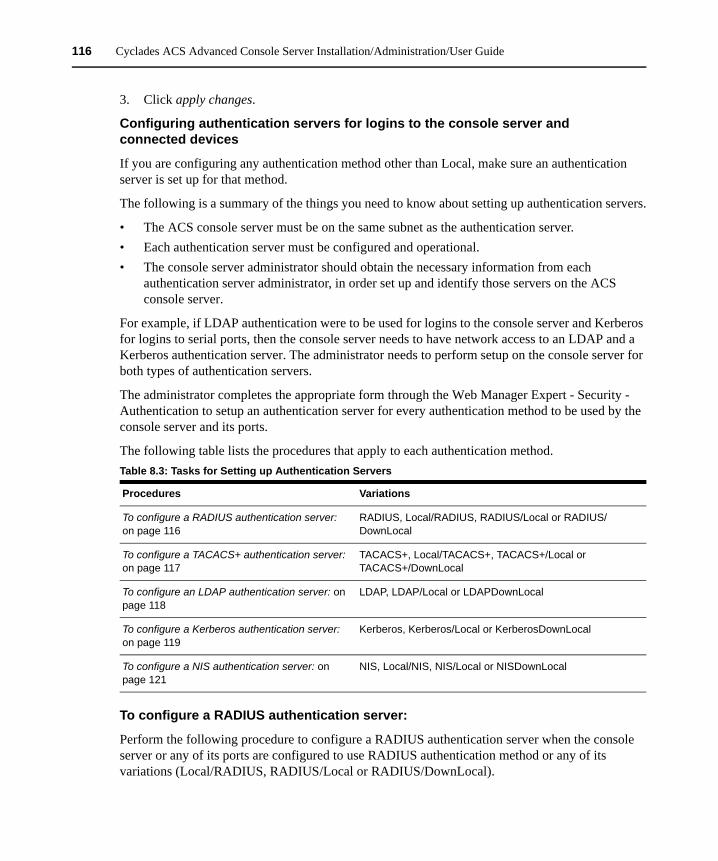
116 Cyclades ACS Advanced Console Server Installation/Administration/User Guide
3. Click apply changes.
Configuring authentication servers for logins to the console server and connected devices
If you are configuring any authentication method other than Local, make sure an authentication server is set up for that method.
The following is a summary of the things you need to know about setting up authentication servers.
• The ACS console server must be on the same subnet as the authentication server. • Each authentication server must be configured and operational.• The console server administrator should obtain the necessary information from each
authentication server administrator, in order set up and identify those servers on the ACS console server.
For example, if LDAP authentication were to be used for logins to the console server and Kerberos for logins to serial ports, then the console server needs to have network access to an LDAP and a Kerberos authentication server. The administrator needs to perform setup on the console server for both types of authentication servers.
The administrator completes the appropriate form through the Web Manager Expert - Security - Authentication to setup an authentication server for every authentication method to be used by the console server and its ports.
The following table lists the procedures that apply to each authentication method.
To configure a RADIUS authentication server:
Perform the following procedure to configure a RADIUS authentication server when the console server or any of its ports are configured to use RADIUS authentication method or any of its variations (Local/RADIUS, RADIUS/Local or RADIUS/DownLocal).
Table 8.3: Tasks for Setting up Authentication Servers
Procedures Variations
To configure a RADIUS authentication server: on page 116
RADIUS, Local/RADIUS, RADIUS/Local or RADIUS/DownLocal
To configure a TACACS+ authentication server: on page 117
TACACS+, Local/TACACS+, TACACS+/Local or TACACS+/DownLocal
To configure an LDAP authentication server: on page 118
LDAP, LDAP/Local or LDAPDownLocal
To configure a Kerberos authentication server: on page 119
Kerberos, Kerberos/Local or KerberosDownLocal
To configure a NIS authentication server: on page 121
NIS, Local/NIS, NIS/Local or NISDownLocal
Chapter 8: Security Menu and Forms 117
1. Go to Security - Authentication - RADIUS in Expert mode.2. Fill in the form according to your local RADIUS server configuration.3. Click apply changes.
Group authorization on RADIUS
Group information retrieval from a RADIUS authentication server adds another layer of security by adding a network-based authorization. It retrieves the group information from the authentication server and performs an authorization through the console server.
To configure a TACACS+ authentication server:
Perform the following procedure to configure a TACACS+ authentication server when the console server or any of its ports are configured to use TACACS+ authentication method or any of its variations (Local/TACACS+, TACACS+/Local or TACACS+/DownLocal).
1. Go to Security - Authentication - TACACS+ in Expert mode. The TACACS+ form displays.2. Fill in the form according to your local TACACS+ server configuration.3. To apply Authorization in addition to authentication to the box and ports, select the Enable
Raccess Authorization checkbox.
By default, Raccess Authorization is disabled and no additional authorization is implemented. When Raccess Authorization is enabled, the authorization level of users trying to access the console server or its ports using TACACS+ authentication is checked. Users with administrator privileges have administrative access and users with regular user privileges have regular user access.
4. To specify a time out period in seconds for each authentication attempt, type a number in the Timeout field.
If the authentication server does not respond to the client’s login attempt before the specified time period, the login attempt is cancelled. The user may retry depending on the number specified in the Retries field on this form.
5. To specify a number of times the user can request authentication verification from the server before sending an authentication failure message to the user, enter a number in the Retries field.
6. Click apply changes.
Group authorization on TACACS+
Using an authorization method in addition to authentication provides an extra level of system security. Selecting Security - Authentication - TACACS+ in Expert mode displays the TACACS+ form where an administrators can configure a TACACS+ authentication server and can also enable user authorization checking.
By checking the Enable Raccess Authorization checkbox, an additional level of security checking is implemented. After each user is successfully authenticated through the standard login procedure,
118 Cyclades ACS Advanced Console Server Installation/Administration/User Guide
the console server uses TACACS+ to determine whether or not each user/group is authorized to access specific serial ports.
By default the Enable Raccess Authorization is disabled allowing all users full authorization. When this feature is enabled by placing a check mark in the box, users/groups are denied access unless they have the proper authorization, which must be set on the TACACS+ authentication server itself. To see the configuration procedures for a TACACS+ authentication server, refer to the Cyclades ACS Command Reference Guide.
To configure an LDAP authentication server:
Perform the following procedure to configure an LDAP authentication server when the console server or any of its ports are configured to use the LDAP authentication method or any of its variations (LDAP, LDAP/Local or LDAPDownLocal).
Before starting this procedure, you will need the following information from the LDAP server administrator:
• The distinguished name of the search base• The LDAP domain name• Whether to use secure LDAP• The authentication server’s IP address
You can enter information in the LDAP User Name, LDAP Password and LDAP Login Attribute fields, but an entry is not required:
Work with the LDAP server administrator to ensure that the following types of accounts are set up on the LDAP server and that the administrators of the console server and the connected devices know the passwords assigned to the accounts:
• An account for admin.• If LDAP authentication is specified for the console server, accounts for all users who need to
log into the console server to administer connected devices.• If LDAP authentication is specified for serial ports, accounts for users who need administrative
access to the connected devices.
To configure LDAP authentication:
1. Select Security - Authentication - LDAP in Expert mode. The LDAP form displays with LDAP Server and LDAP Base fields filled in from with the current values in the /etc/ldap.conf file.
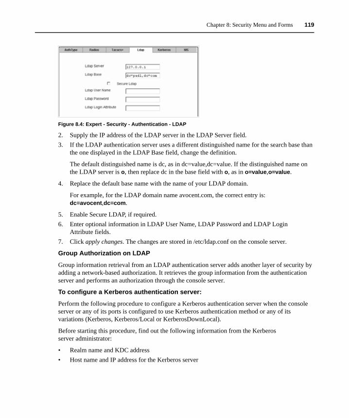
Chapter 8: Security Menu and Forms 119
Figure 8.4: Expert - Security - Authentication - LDAP
2. Supply the IP address of the LDAP server in the LDAP Server field.3. If the LDAP authentication server uses a different distinguished name for the search base than
the one displayed in the LDAP Base field, change the definition.
The default distinguished name is dc, as in dc=value,dc=value. If the distinguished name on the LDAP server is o, then replace dc in the base field with o, as in o=value,o=value.
4. Replace the default base name with the name of your LDAP domain.
For example, for the LDAP domain name avocent.com, the correct entry is: dc=avocent,dc=com.
5. Enable Secure LDAP, if required.6. Enter optional information in LDAP User Name, LDAP Password and LDAP Login
Attribute fields.7. Click apply changes. The changes are stored in /etc/ldap.conf on the console server.
Group Authorization on LDAP
Group information retrieval from an LDAP authentication server adds another layer of security by adding a network-based authorization. It retrieves the group information from the authentication server and performs an authorization through the console server.
To configure a Kerberos authentication server:
Perform the following procedure to configure a Kerberos authentication server when the console server or any of its ports is configured to use Kerberos authentication method or any of its variations (Kerberos, Kerberos/Local or KerberosDownLocal).
Before starting this procedure, find out the following information from the Kerberos server administrator:
• Realm name and KDC address• Host name and IP address for the Kerberos server
120 Cyclades ACS Advanced Console Server Installation/Administration/User Guide
Also, work with the Kerberos server’s administrator to ensure that following types of accounts are set up on the Kerberos server and that the administrators of the console server and connected devices know the passwords assigned to the accounts:
• An account for admin• If Kerberos authentication is specified for the console server, accounts will be needed for all
users who need to log into the console server to administer connected devices• If Kerberos authentication is specified for the serial ports, accounts for users who need
administrative access to connected devices
Make sure an entry for the console server and the Kerberos server exist in the console server’s /etc/hosts file.
1. Go to Network - Host Table in Expert mode. The Host Table form appears.2. Add an entry for the console server if none exists and an entry for the Kerberos server.
a. Click Add. The New/Modify Host dialog appears.b. Enter the address in the IP Address field.c. Enter the name in the Name field.d. Enter an optional alias in the Alias field.
3. Make sure that time, date and timezone settings are synchronized on the console server and on the Kerberos server.
NOTE: Kerberos authentication depends on time synchronization. Time and date synchronization can be achieved by setting both the console server and the Kerberos server to use the same NTP server.
4. To specify an NTP server, see To configure time and date using an NTP server: on page 163.5. To set the time and date on the console server manually, see To set the time and date manually:
on page 163.6. Work with the Kerberos authentication server administrator to synchronize the time and date
between the console server and the Kerberos server.7. Set the timezone on the console server by going to Administration - Time/Date in Expert mode
as shown in the following figure. The default is GMT.
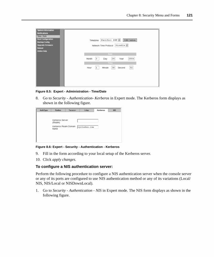
Chapter 8: Security Menu and Forms 121
Figure 8.5: Expert - Administration - Time/Date
8. Go to Security - Authentication- Kerberos in Expert mode. The Kerberos form displays as shown in the following figure.
Figure 8.6: Expert - Security - Authentication - Kerberos
9. Fill in the form according to your local setup of the Kerberos server.10. Click apply changes.
To configure a NIS authentication server:
Perform the following procedure to configure a NIS authentication server when the console server or any of its ports are configured to use NIS authentication method or any of its variations (Local/NIS, NIS/Local or NISDownLocal).
1. Go to Security - Authentication - NIS in Expert mode. The NIS form displays as shown in the following figure.
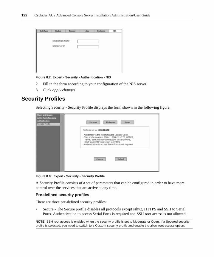
122 Cyclades ACS Advanced Console Server Installation/Administration/User Guide
Figure 8.7: Expert - Security - Authentication - NIS
2. Fill in the form according to your configuration of the NIS server.3. Click apply changes.
Security ProfilesSelecting Security - Security Profile displays the form shown in the following figure.
Figure 8.8: Expert - Security - Security Profile
A Security Profile consists of a set of parameters that can be configured in order to have more control over the services that are active at any time.
Pre-defined security profiles
There are three pre-defined security profiles:
• Secure - The Secure profile disables all protocols except sshv2, HTTPS and SSH to Serial Ports. Authentication to access Serial Ports is required and SSH root access is not allowed.
NOTE: SSH root access is enabled when the security profile is set to Moderate or Open. If a Secured security profile is selected, you need to switch to a Custom security profile and enable the allow root access option.
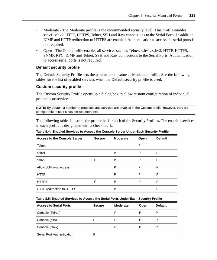
Chapter 8: Security Menu and Forms 123
• Moderate - The Moderate profile is the recommended security level. This profile enables sshv1, sshv2, HTTP, HTTPS, Telnet, SSH and Raw connections to the Serial Ports. In addition, ICMP and HTTP redirection to HTTPS are enabled. Authentication to access the serial ports is not required.
• Open - The Open profile enables all services such as Telnet, sshv1, sshv2, HTTP, HTTPS, SNMP, RPC, ICMP and Telnet, SSH and Raw connections to the Serial Ports. Authentication to access serial ports is not required.
Default security profile
The Default Security Profile sets the parameters to same as Moderate profile. See the following tables for the list of enabled services when the Default security profile is used.
Custom security profile
The Custom Security Profile opens up a dialog box to allow custom configuration of individual protocols or services.
NOTE: By default, a number of protocols and services are enabled in the Custom profile, however, they are configurable to user’s custom requirements.
The following tables illustrate the properties for each of the Security Profiles. The enabled services in each profile is designated with a check mark.Table 8.4: Enabled Services to Access the Console Server Under Each Security Profile
Access to the Console Server Secure Moderate Open Default
Telnet P
sshv1 P P P
sshv2 P P P P
Allow SSH root access P P P
HTTP P P P
HTTPS P P P P
HTTP redirection to HTTPS P P
Table 8.5: Enabled Services to Access the Serial Ports Under Each Security Profile
Access to Serial Ports Secure Moderate Open Default
Console (Telnet) P P P
Console (ssh) P P P P
Console (Raw) P P P
Serial Port Authentication P
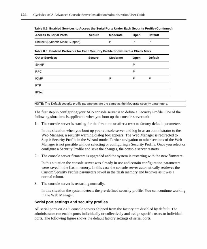
124 Cyclades ACS Advanced Console Server Installation/Administration/User Guide
NOTE: The Default security profile parameters are the same as the Moderate security parameters.
The first step in configuring your ACS console server is to define a Security Profile. One of the following situations is applicable when you boot up the console server unit.
1. The console server is starting for the first time or after a reset to factory default parameters.
In this situation when you boot up your console server and log in as an administrator to the Web Manager, a security warning dialog box appears. The Web Manager is redirected to Step1: Security Profile in the Wizard mode. Further navigation to other sections of the Web Manager is not possible without selecting or configuring a Security Profile. Once you select or configure a Security Profile and save the changes, the console server restarts.
2. The console server firmware is upgraded and the system is restarting with the new firmware.
In this situation the console server was already in use and certain configuration parameters were saved in the flash memory. In this case the console server automatically retrieves the Custom Security Profile parameters saved in the flash memory and behaves as it was a normal reboot.
3. The console server is restarting normally.
In this situation the system detects the pre-defined security profile. You can continue working in the Web Manager.
Serial port settings and security profiles
All serial ports on ACS console servers shipped from the factory are disabled by default. The administrator can enable ports individually or collectively and assign specific users to individual ports. The following figure shows the default factory settings of serial ports.
Bidirect (Dynamic Mode Support) P P P
Table 8.6: Enabled Protocols for Each Security Profile Shown with a Check Mark
Other Services Secure Moderate Open Default
SNMP P
RPC P
ICMP P P P
FTP
IPSec
Table 8.5: Enabled Services to Access the Serial Ports Under Each Security Profile (Continued)
Access to Serial Ports Secure Moderate Open Default
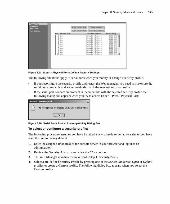
Chapter 8: Security Menu and Forms 125
Figure 8.9: Expert - Physical Ports Default Factory Settings
The following situations apply to serial ports when you modify or change a security profile.
• If you reconfigure the security profile and restart the Web manager, you need to make sure the serial ports protocols and access methods match the selected security profile.
• If the serial port connection protocol is incompatible with the selected security profile the following dialog box appears when you try to access Expert - Ports - Physical Ports
Figure 8.10: Serial Ports Protocol Incompatibility Dialog Box
To select or configure a security profile:
The following procedure assumes you have installed a new console server at your site or you have reset the unit to factory default.
1. Enter the assigned IP address of the console server in your browser and log in as an administrator.
2. Review the Security Advisory and click the Close button.3. The Web Manager is redirected to Wizard - Step 1: Security Profile.4. Select a pre-defined Security Profile by pressing one of the Secure, Moderate, Open or Default
profiles or create a Custom profile. The following dialog box appears when you select the Custom profile.
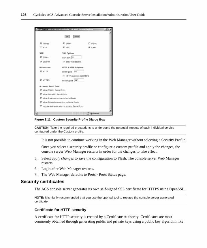
126 Cyclades ACS Advanced Console Server Installation/Administration/User Guide
Figure 8.11: Custom Security Profile Dialog Box
CAUTION: Take the required precautions to understand the potential impacts of each individual service configured under the Custom profile.
It is not possible to continue working in the Web Manager without selecting a Security Profile.
Once you select a security profile or configure a custom profile and apply the changes, the console server Web Manager restarts in order for the changes to take effect.
5. Select apply changes to save the configuration to Flash. The console server Web Manager restarts.
6. Login after Web Manager restarts.7. The Web Manager defaults to Ports - Ports Status page.
Security certificatesThe ACS console server generates its own self-signed SSL certificate for HTTPS using OpenSSL.
NOTE: It is highly recommended that you use the openssl tool to replace the console server generated certificate.
Certificate for HTTP security
A certificate for HTTP security is created by a Certificate Authority. Certificates are most commonly obtained through generating public and private keys using a public key algorithm like
Chapter 8: Security Menu and Forms 127
RSA or X.509. The keys can be generated by using a key generator software. The procedures to obtain a Signed Digital Certificate is documented in the ACS Command Reference Guide, Chapter 3 Authentication, Section 3.7 Certificate for HTTP Security.
User configured digital certificate
You can generate a self-signed digital certificate. It is highly recommended that you use the openssl tool to generate a self-signed certificate and replace the console server generated certificate.The procedures to configure a self-signed digital certificate is documented in the Cyclades ACS Command Reference Guide.
X.509 certificate on ssh
The OpenSSH software included with the console server has support for X.509 certificates. The administrator must activate and configure the SSH to use X.509. In order to implement authentication of SSH sessions through exchange of X.509 certificates please refer to the configuration procedures described in the Cyclades ACS Command Reference Guide.

128 Cyclades ACS Advanced Console Server Installation/Administration/User Guide
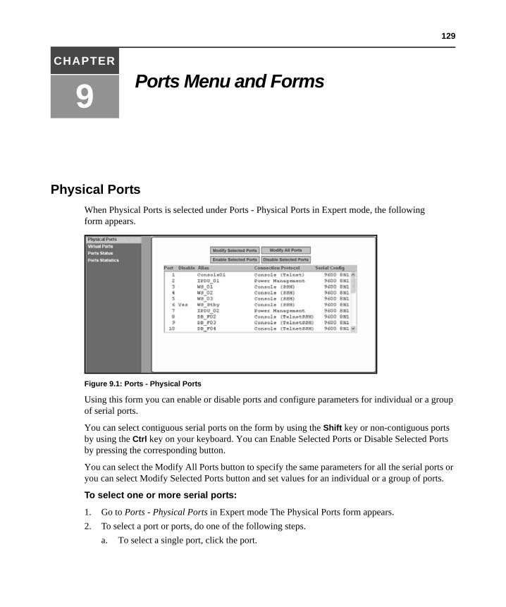
129
CHAPTER
9 Ports Menu and Forms
Physical PortsWhen Physical Ports is selected under Ports - Physical Ports in Expert mode, the following form appears.
Figure 9.1: Ports - Physical Ports
Using this form you can enable or disable ports and configure parameters for individual or a group of serial ports.
You can select contiguous serial ports on the form by using the Shift key or non-contiguous ports by using the Ctrl key on your keyboard. You can Enable Selected Ports or Disable Selected Ports by pressing the corresponding button.
You can select the Modify All Ports button to specify the same parameters for all the serial ports or you can select Modify Selected Ports button and set values for an individual or a group of ports.
To select one or more serial ports:
1. Go to Ports - Physical Ports in Expert mode The Physical Ports form appears.2. To select a port or ports, do one of the following steps.
a. To select a single port, click the port.
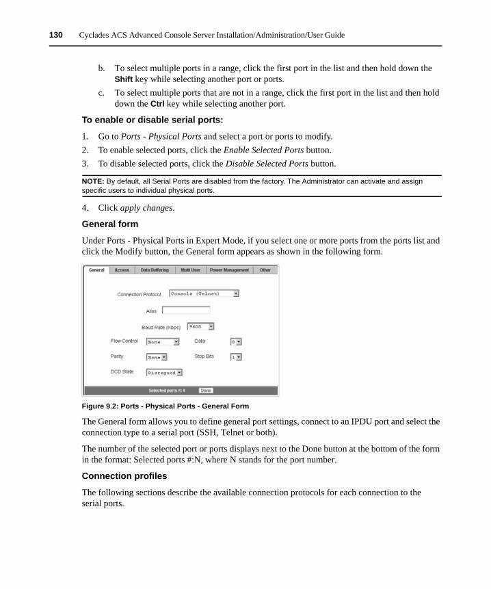
130 Cyclades ACS Advanced Console Server Installation/Administration/User Guide
b. To select multiple ports in a range, click the first port in the list and then hold down the Shift key while selecting another port or ports.
c. To select multiple ports that are not in a range, click the first port in the list and then hold down the Ctrl key while selecting another port.
To enable or disable serial ports:
1. Go to Ports - Physical Ports and select a port or ports to modify.2. To enable selected ports, click the Enable Selected Ports button.3. To disable selected ports, click the Disable Selected Ports button.
NOTE: By default, all Serial Ports are disabled from the factory. The Administrator can activate and assign specific users to individual physical ports.
4. Click apply changes.
General form
Under Ports - Physical Ports in Expert Mode, if you select one or more ports from the ports list and click the Modify button, the General form appears as shown in the following form.
Figure 9.2: Ports - Physical Ports - General Form
The General form allows you to define general port settings, connect to an IPDU port and select the connection type to a serial port (SSH, Telnet or both).
The number of the selected port or ports displays next to the Done button at the bottom of the form in the format: Selected ports #:N, where N stands for the port number.
Connection profiles
The following sections describe the available connection protocols for each connection to the serial ports.
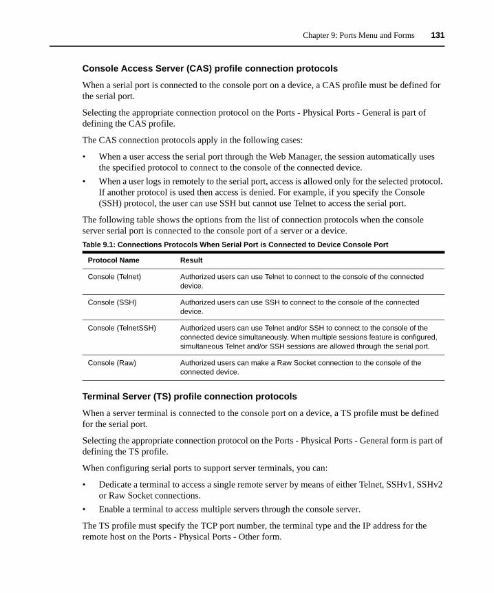
Chapter 9: Ports Menu and Forms 131
Console Access Server (CAS) profile connection protocols
When a serial port is connected to the console port on a device, a CAS profile must be defined for the serial port.
Selecting the appropriate connection protocol on the Ports - Physical Ports - General is part of defining the CAS profile.
The CAS connection protocols apply in the following cases:
• When a user access the serial port through the Web Manager, the session automatically uses the specified protocol to connect to the console of the connected device.
• When a user logs in remotely to the serial port, access is allowed only for the selected protocol. If another protocol is used then access is denied. For example, if you specify the Console (SSH) protocol, the user can use SSH but cannot use Telnet to access the serial port.
The following table shows the options from the list of connection protocols when the console server serial port is connected to the console port of a server or a device.
Terminal Server (TS) profile connection protocols
When a server terminal is connected to the console port on a device, a TS profile must be defined for the serial port.
Selecting the appropriate connection protocol on the Ports - Physical Ports - General form is part of defining the TS profile.
When configuring serial ports to support server terminals, you can:
• Dedicate a terminal to access a single remote server by means of either Telnet, SSHv1, SSHv2 or Raw Socket connections.
• Enable a terminal to access multiple servers through the console server.
The TS profile must specify the TCP port number, the terminal type and the IP address for the remote host on the Ports - Physical Ports - Other form.
Table 9.1: Connections Protocols When Serial Port is Connected to Device Console Port
Protocol Name Result
Console (Telnet) Authorized users can use Telnet to connect to the console of the connected device.
Console (SSH) Authorized users can use SSH to connect to the console of the connected device.
Console (TelnetSSH) Authorized users can use Telnet and/or SSH to connect to the console of the connected device simultaneously. When multiple sessions feature is configured, simultaneous Telnet and/or SSH sessions are allowed through the serial port.
Console (Raw) Authorized users can make a Raw Socket connection to the console of the connected device.
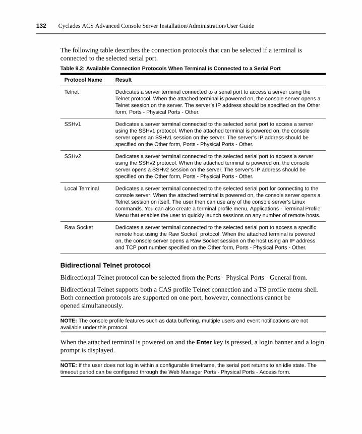
132 Cyclades ACS Advanced Console Server Installation/Administration/User Guide
The following table describes the connection protocols that can be selected if a terminal is connected to the selected serial port.
Bidirectional Telnet protocol
Bidirectional Telnet protocol can be selected from the Ports - Physical Ports - General from.
Bidirectional Telnet supports both a CAS profile Telnet connection and a TS profile menu shell. Both connection protocols are supported on one port, however, connections cannot be opened simultaneously.
NOTE: The console profile features such as data buffering, multiple users and event notifications are not available under this protocol.
When the attached terminal is powered on and the Enter key is pressed, a login banner and a login prompt is displayed.
NOTE: If the user does not log in within a configurable timeframe, the serial port returns to an idle state. The timeout period can be configured through the Web Manager Ports - Physical Ports - Access form.
Table 9.2: Available Connection Protocols When Terminal is Connected to a Serial Port
Protocol Name Result
Telnet Dedicates a server terminal connected to a serial port to access a server using the Telnet protocol. When the attached terminal is powered on, the console server opens a Telnet session on the server. The server’s IP address should be specified on the Other form, Ports - Physical Ports - Other.
SSHv1 Dedicates a server terminal connected to the selected serial port to access a server using the SSHv1 protocol. When the attached terminal is powered on, the console server opens an SSHv1 session on the server. The server’s IP address should be specified on the Other form, Ports - Physical Ports - Other.
SSHv2 Dedicates a server terminal connected to the selected serial port to access a server using the SSHv2 protocol. When the attached terminal is powered on, the console server opens a SSHv2 session on the server. The server’s IP address should be specified on the Other form, Ports - Physical Ports - Other.
Local Terminal Dedicates a server terminal connected to the selected serial port for connecting to the console server. When the attached terminal is powered on, the console server opens a Telnet session on itself. The user then can use any of the console server’s Linux commands. You can also create a terminal profile menu, Applications - Terminal Profile Menu that enables the user to quickly launch sessions on any number of remote hosts.
Raw Socket Dedicates a server terminal connected to the selected serial port to access a specific remote host using the Raw Socket protocol. When the attached terminal is powered on, the console server opens a Raw Socket session on the host using an IP address and TCP port number specified on the Other form, Ports - Physical Ports - Other.
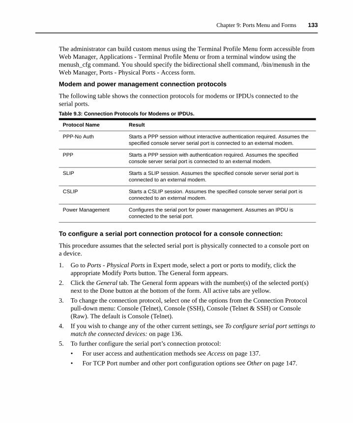
Chapter 9: Ports Menu and Forms 133
The administrator can build custom menus using the Terminal Profile Menu form accessible from Web Manager, Applications - Terminal Profile Menu or from a terminal window using the menush_cfg command. You should specify the bidirectional shell command, /bin/menush in the Web Manager, Ports - Physical Ports - Access form.
Modem and power management connection protocols
The following table shows the connection protocols for modems or IPDUs connected to the serial ports.
To configure a serial port connection protocol for a console connection:
This procedure assumes that the selected serial port is physically connected to a console port on a device.
1. Go to Ports - Physical Ports in Expert mode, select a port or ports to modify, click the appropriate Modify Ports button. The General form appears.
2. Click the General tab. The General form appears with the number(s) of the selected port(s) next to the Done button at the bottom of the form. All active tabs are yellow.
3. To change the connection protocol, select one of the options from the Connection Protocol pull-down menu: Console (Telnet), Console (SSH), Console (Telnet & SSH) or Console (Raw). The default is Console (Telnet).
4. If you wish to change any of the other current settings, see To configure serial port settings to match the connected devices: on page 136.
5. To further configure the serial port’s connection protocol:• For user access and authentication methods see Access on page 137.• For TCP Port number and other port configuration options see Other on page 147.
Table 9.3: Connection Protocols for Modems or IPDUs.
Protocol Name Result
PPP-No Auth Starts a PPP session without interactive authentication required. Assumes the specified console server serial port is connected to an external modem.
PPP Starts a PPP session with authentication required. Assumes the specified console server serial port is connected to an external modem.
SLIP Starts a SLIP session. Assumes the specified console server serial port is connected to an external modem.
CSLIP Starts a CSLIP session. Assumes the specified console server serial port is connected to an external modem.
Power Management Configures the serial port for power management. Assumes an IPDU is connected to the serial port.

134 Cyclades ACS Advanced Console Server Installation/Administration/User Guide
To configure a serial port connection protocol for a Bidirectional Telnet:
The following procedure assumes that the selected serial port is physically connected to a terminal. For more information on Bidirectional Telnet connection protocol see Bidirectional Telnet protocol on page 132.
1. Go to Ports - Physical Ports in Expert mode, select a port or ports to modify, click the appropriate Modify Ports button. The General form appears.
2. Click the General tab. The General form appears with the number(s) of the selected port(s) next to the Done button at the bottom of the form and the active tabs are yellow.
3. To change the connection protocol, select Bidirectional Telnet from the Connection Protocol pull-down menu.
4. If you wish to change any of the other current settings, see To configure serial port settings to match the connected devices: on page 136.
5. Go to the Access tab and configure the following settings:a. In the Authorized Users/Groups field restrict or deny access to a serial port by specifying
one or more users or groups.b. From the Type pull-down menu, select an authentication type for the serial port. The
default is no authentication (Type=None).c. In the BidirectionLogin Timeout field enter the time for the serial port to return to idle
state. When the user name is not entered in the terminal window after the login banner is displayed, the serial port returns to an idle state. The default timeout value is 60 seconds.
d. In the BidirectionShell Command field enter the menu shell command, for example, /bin/menush to build a custom menu for the TS profile.
6. To customize a menu shell, go to Web Manager - Applications - Terminal Profile Menu form. For more information on configuring a menu shell see Chapter 6, “Expert - Applications - Terminal Profile Menu” on page 69.
To configure a serial port connection protocol for a terminal server:
This procedure assumes that the selected serial port is physically connected to a terminal. For more information on Terminal Server connection protocols see Terminal Server (TS) profile connection protocols on page 131.
1. Go to Ports - Physical Ports in Expert mode, select a port or ports to modify, click the appropriate Modify Ports button.The General form appears.
2. Click the General tab. The General form appears with the number(s) of the selected port(s) next to the Done button at the bottom of the form and the active tabs are in yellow.
3. To change the connection protocol, select a Terminal Server connection from the Connection Protocol pull-down menu, Telnet, SSHv1, SSHv2, Local Terminal or Raw Socket.
4. To configure a terminal to automatically connect to the console server, perform the following steps:

Chapter 9: Ports Menu and Forms 135
a. Select Local Terminal from the Connection Protocol pull-down menu.b. Define a terminal profile menu. Terminal Profile Menu form is at Expert - Applications -
Terminal Profile Menu. 5. To configure a terminal to automatically connect to a server, perform the following steps:
a. Select Telnet, SSHv1, SSHv2 or Raw Socket from the Connection Protocol pull-down menu.
b. Specify authorized users/groups and the authentication method in the Access form.c. Specify the TCP Port number, the IP address of the remote host and the terminal type
using the Other form. The Other form is located at Ports - Physical Ports - Modify Selected Ports - Other.
6. If you are finished, click Done.7. Click apply changes.
To configure a serial port connection protocol for an external modem:
This procedure assumes that the selected serial port is physically connected to an external modem.
1. Go to Ports - Physical Ports in Expert mode, select a port or ports to modify, click the appropriate Modify Ports button. The General form appears.
2. Click the General tab. The General form appears with the number(s) of the selected port(s) next to the Done button at the bottom of the form and the active tabs are in yellow.
3. To change the connection protocol, select one of the options from the Connection Protocol pull-down menu: PPP-No Auth., PPP, SLIP or CSLIP.
4. If you wish to change any of the other current settings, see To configure serial port settings to match the connected devices: on page 136.
5. To further configure the serial port’s connection protocol:• For user access and authentication methods, see Access on page 137.• To specify the TCP Port number and configure modem initialization and PPP options see
Other on page 147. 6. If you are finished, click Done.7. Click apply changes.
To configure a power management protocol for an IPDU:
This procedure assumes that an IPDU is physically connected to the selected serial port.
1. Go to Ports - Physical Ports in Expert mode, select a port or ports to modify, click the appropriate Modify Ports button. The General form appears.
2. Click the General tab. The General form appears with the number(s) of the selected port(s) next to the Done button at the bottom of the form.
3. To change the connection protocol, select Power Management from the Connection Protocol pull-down menu.

136 Cyclades ACS Advanced Console Server Installation/Administration/User Guide
4. Enter a desired name for the IPDU in the Alias field. 5. Select an access method for the IPDU from the Allow Access by pull-down menu. The options
are SSH, Telnet or SSH and Telnet. Selecting an access option activates the Access and Other tabs.
6. Go to the Access tab.a. Enter the users/groups authorized to access the serial port.b. Select an authentication type for the serial port from the pull-down menu.
NOTE: Authentication type None is not a valid option when the serial port is configured for Power Management connection protocol. The system defaults to Local if no authentication type is selected.
NOTE: Configuration for One Time Password (OTP) and OTP/Local is documented in the Cyclades ACS Command Reference Guide.
7. Select the Other tab. There are two fields: TCP Port and Port IP Alias.a. A default TCP port number is displayed in the TCP Port field. Enter an alternate port
number if you are overriding the default. b. In the IP Alias field, enter the IP address for the port for direct telnet or SSH access (the
same address used when the port is configured for console access).
NOTE: For the IP Alias address to work properly, you must select Allow Access by Telnet of SSH or both in the General tab form.
8. When finished, click Done.9. Click apply changes.
To associate an alias to a serial port:
An alias can be associated to a port when it is individually selected for modification. To associate an alias to a port perform the following steps.
1. Go to Ports - Physical Ports in Expert mode, select a port to modify and click the Modify Ports button.
2. Enter the desired string in the Alias field.3. Click Done.4. Click apply changes.
NOTE: The Alias field cannot be set if you select the Modify All Ports.
To configure serial port settings to match the connected devices:
The settings for a serial port must match the connection settings on the connected device.
1. Go to Ports - Physical Ports in Expert mode and select a port or ports to modify. The General form appears.
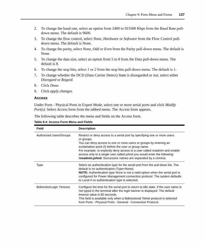
Chapter 9: Ports Menu and Forms 137
2. To change the baud rate, select an option from 2400 to 921600 Kbps from the Baud Rate pull-down menu. The default is 9600.
3. To change the flow control, select None, Hardware or Software from the Flow Control pull-down menu. The default is None.
4. To change the parity, select None, Odd or Even from the Parity pull-down menu. The default is None.
5. To change the data size, select an option from 5 to 8 from the Data pull-down menu. The default is 8.
6. To change the stop bits, select 1 or 2 from the stop bits pull-down menu. The default is 1.7. To change whether the DCD (Data Carrier Detect) State is disregarded or not, select either
Disregard or Regard.8. Click Done.9. Click apply changes.
Access
Under Ports - Physical Ports in Expert Mode, select one or more serial ports and click Modify Port(s). Select Access form from the tabbed menu. The Access form appears.
The following table describes the menu and fields on the Access form.Table 9.4: Access Form Menu and Fields
Field Description
Authorized Users/Groups Restrict or deny access to a serial port by specifying one or more users or groups.You can deny access to one or more users or groups by entering an exclamation point (!) before the user or group name. For example, to explicitly deny access to a user called noadmin and enable access only to a single user called johnd you would enter the following:!noadmin,johnd. Successive names are separated by a comma.
Type Select an authentication type for the serial port from the pull-down list. The default is no authentication (Type=None). NOTE: Authentication type None is not a valid option when the serial port is configured for Power Management connection protocol. The system defaults to Local if no authentication type is selected.
BidirectionLogin Timeout Configure the time for the serial port to return to idle state, if the user name is not typed in the terminal after the login banner is displayed. The default timeout value is 60 seconds.This field is available only when a Bidirectional Telnet protocol is selected from Ports - Physical Ports - General - Connection Protocol.
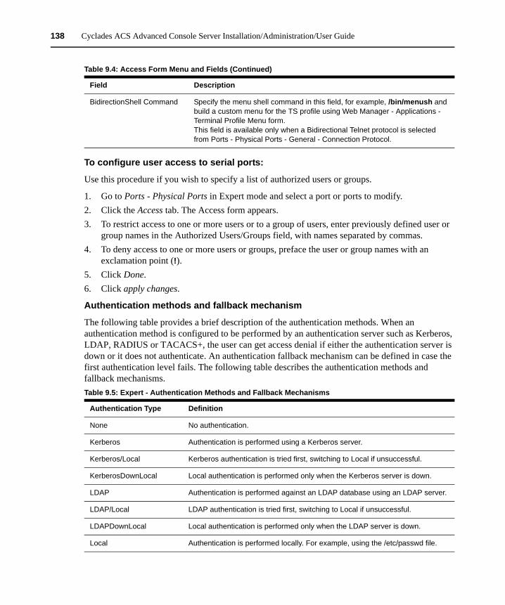
138 Cyclades ACS Advanced Console Server Installation/Administration/User Guide
To configure user access to serial ports:
Use this procedure if you wish to specify a list of authorized users or groups.
1. Go to Ports - Physical Ports in Expert mode and select a port or ports to modify.2. Click the Access tab. The Access form appears.3. To restrict access to one or more users or to a group of users, enter previously defined user or
group names in the Authorized Users/Groups field, with names separated by commas.4. To deny access to one or more users or groups, preface the user or group names with an
exclamation point (!).5. Click Done.6. Click apply changes.
Authentication methods and fallback mechanism
The following table provides a brief description of the authentication methods. When an authentication method is configured to be performed by an authentication server such as Kerberos, LDAP, RADIUS or TACACS+, the user can get access denial if either the authentication server is down or it does not authenticate. An authentication fallback mechanism can be defined in case the first authentication level fails. The following table describes the authentication methods and fallback mechanisms.
BidirectionShell Command Specify the menu shell command in this field, for example, /bin/menush and build a custom menu for the TS profile using Web Manager - Applications - Terminal Profile Menu form.This field is available only when a Bidirectional Telnet protocol is selected from Ports - Physical Ports - General - Connection Protocol.
Table 9.5: Expert - Authentication Methods and Fallback Mechanisms
Authentication Type Definition
None No authentication.
Kerberos Authentication is performed using a Kerberos server.
Kerberos/Local Kerberos authentication is tried first, switching to Local if unsuccessful.
KerberosDownLocal Local authentication is performed only when the Kerberos server is down.
LDAP Authentication is performed against an LDAP database using an LDAP server.
LDAP/Local LDAP authentication is tried first, switching to Local if unsuccessful.
LDAPDownLocal Local authentication is performed only when the LDAP server is down.
Local Authentication is performed locally. For example, using the /etc/passwd file.
Table 9.4: Access Form Menu and Fields (Continued)
Field Description
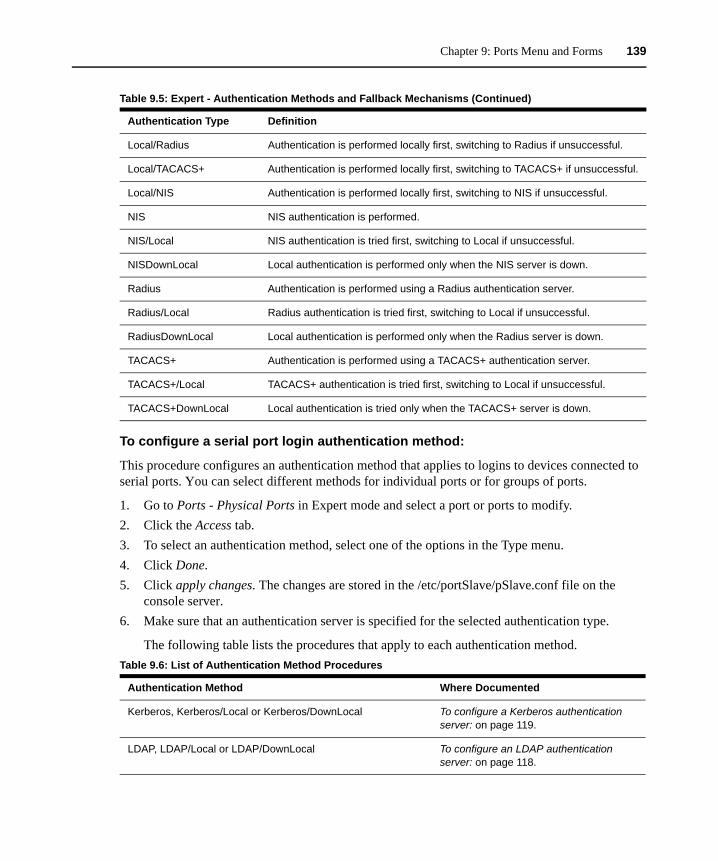
Chapter 9: Ports Menu and Forms 139
To configure a serial port login authentication method:
This procedure configures an authentication method that applies to logins to devices connected to serial ports. You can select different methods for individual ports or for groups of ports.
1. Go to Ports - Physical Ports in Expert mode and select a port or ports to modify.2. Click the Access tab.3. To select an authentication method, select one of the options in the Type menu.4. Click Done.5. Click apply changes. The changes are stored in the /etc/portSlave/pSlave.conf file on the
console server.6. Make sure that an authentication server is specified for the selected authentication type.
The following table lists the procedures that apply to each authentication method.
Local/Radius Authentication is performed locally first, switching to Radius if unsuccessful.
Local/TACACS+ Authentication is performed locally first, switching to TACACS+ if unsuccessful.
Local/NIS Authentication is performed locally first, switching to NIS if unsuccessful.
NIS NIS authentication is performed.
NIS/Local NIS authentication is tried first, switching to Local if unsuccessful.
NISDownLocal Local authentication is performed only when the NIS server is down.
Radius Authentication is performed using a Radius authentication server.
Radius/Local Radius authentication is tried first, switching to Local if unsuccessful.
RadiusDownLocal Local authentication is performed only when the Radius server is down.
TACACS+ Authentication is performed using a TACACS+ authentication server.
TACACS+/Local TACACS+ authentication is tried first, switching to Local if unsuccessful.
TACACS+DownLocal Local authentication is tried only when the TACACS+ server is down.
Table 9.6: List of Authentication Method Procedures
Authentication Method Where Documented
Kerberos, Kerberos/Local or Kerberos/DownLocal To configure a Kerberos authentication server: on page 119.
LDAP, LDAP/Local or LDAP/DownLocal To configure an LDAP authentication server: on page 118.
Table 9.5: Expert - Authentication Methods and Fallback Mechanisms (Continued)
Authentication Type Definition
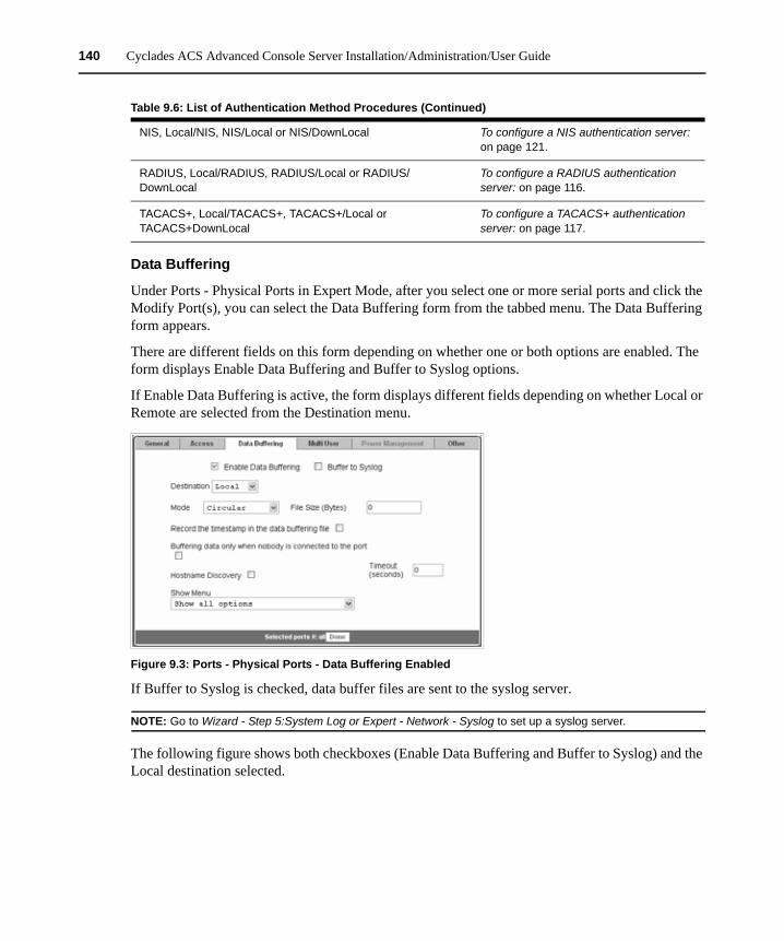
140 Cyclades ACS Advanced Console Server Installation/Administration/User Guide
Data Buffering
Under Ports - Physical Ports in Expert Mode, after you select one or more serial ports and click the Modify Port(s), you can select the Data Buffering form from the tabbed menu. The Data Buffering form appears.
There are different fields on this form depending on whether one or both options are enabled. The form displays Enable Data Buffering and Buffer to Syslog options.
If Enable Data Buffering is active, the form displays different fields depending on whether Local or Remote are selected from the Destination menu.
Figure 9.3: Ports - Physical Ports - Data Buffering Enabled
If Buffer to Syslog is checked, data buffer files are sent to the syslog server.
NOTE: Go to Wizard - Step 5:System Log or Expert - Network - Syslog to set up a syslog server.
The following figure shows both checkboxes (Enable Data Buffering and Buffer to Syslog) and the Local destination selected.
NIS, Local/NIS, NIS/Local or NIS/DownLocal To configure a NIS authentication server: on page 121.
RADIUS, Local/RADIUS, RADIUS/Local or RADIUS/DownLocal
To configure a RADIUS authentication server: on page 116.
TACACS+, Local/TACACS+, TACACS+/Local or TACACS+DownLocal
To configure a TACACS+ authentication server: on page 117.
Table 9.6: List of Authentication Method Procedures (Continued)
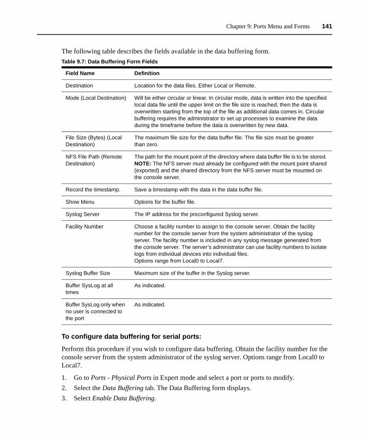
Chapter 9: Ports Menu and Forms 141
The following table describes the fields available in the data buffering form.
To configure data buffering for serial ports:
Perform this procedure if you wish to configure data buffering. Obtain the facility number for the console server from the system administrator of the syslog server. Options range from Local0 to Local7.
1. Go to Ports - Physical Ports in Expert mode and select a port or ports to modify.2. Select the Data Buffering tab. The Data Buffering form displays.3. Select Enable Data Buffering.
Table 9.7: Data Buffering Form Fields
Field Name Definition
Destination Location for the data files. Either Local or Remote.
Mode (Local Destination) Will be either circular or linear. In circular mode, data is written into the specified local data file until the upper limit on the file size is reached; then the data is overwritten starting from the top of the file as additional data comes in. Circular buffering requires the administrator to set up processes to examine the data during the timeframe before the data is overwritten by new data.
File Size (Bytes) (Local Destination)
The maximum file size for the data buffer file. The file size must be greater than zero.
NFS File Path (Remote Destination)
The path for the mount point of the directory where data buffer file is to be stored. NOTE: The NFS server must already be configured with the mount point shared (exported) and the shared directory from the NFS server must be mounted on the console server.
Record the timestamp. Save a timestamp with the data in the data buffer file.
Show Menu Options for the buffer file.
Syslog Server The IP address for the preconfigured Syslog server.
Facility Number Choose a facility number to assign to the console server. Obtain the facility number for the console server from the system administrator of the syslog server. The facility number is included in any syslog message generated from the console server. The server’s administrator can use facility numbers to isolate logs from individual devices into individual files. Options range from Local0 to Local7.
Syslog Buffer Size Maximum size of the buffer in the Syslog server.
Buffer SysLog at all times
As indicated.
Buffer SysLog only when no user is connected to the port
As indicated.

142 Cyclades ACS Advanced Console Server Installation/Administration/User Guide
4. From the Destination pull-down menu, choose Local or Remote to specify whether the data buffer files are stored locally or remotely on a file server.
5. If you chose Local from the Destination pull-down menu, perform the following:a. Choose Circular or Linear from the Mode pull-down menu.b. Enter a size larger than 0 in the File Size (Bytes) field.
6. If you chose Remote from the Destination pull-down menu, enter the NFS mount point for the directory where data buffer file is to be stored in the NFS File Path field.
NOTE: If you are configuring data buffer files to be stored remotely, make sure that a system administrator has already configured an NFS server and shared the mount point.
7. Click the checkbox next to Record to specify whether to include a timestamp with the data.8. From the Show Menu pull-down menu, choose Show all options, No, Show data buffering file
only or Show without the erase options.9. If you checked Buffer to Syslog, enter the IP address of the syslog server in the Syslog Server
field.10. Choose an option from the Facility Number pull-down menu.11. Enter the maximum size of the buffer in the Syslog Buffer Size field.12. Click the radio button next to one of the following options:
a. Buffer Syslog at all timesb. Buffer only when no user is connected to the port
13. Click Done.14. Click apply changes.
To configure alarm notifications to be sent based on the type of buffered data, select Expert - Administration - Notifications.
Multi User
Under Ports - Physical Ports in Expert Mode, after you select one or more serial ports and click Modify Port(s), you can select Multi User from the tabbed menu. The Multi User form appears.
The Multi User form enables you to open more than one session from the same serial port. Multiple users can connect simultaneously to a serial port. To connect to a port or start a shared session, the user must have permission to access the port. If you allow multiple sessions through Allow Multiple Sessions pull-down menu, the Privilege Users field should be populated with the user names who have access rights.
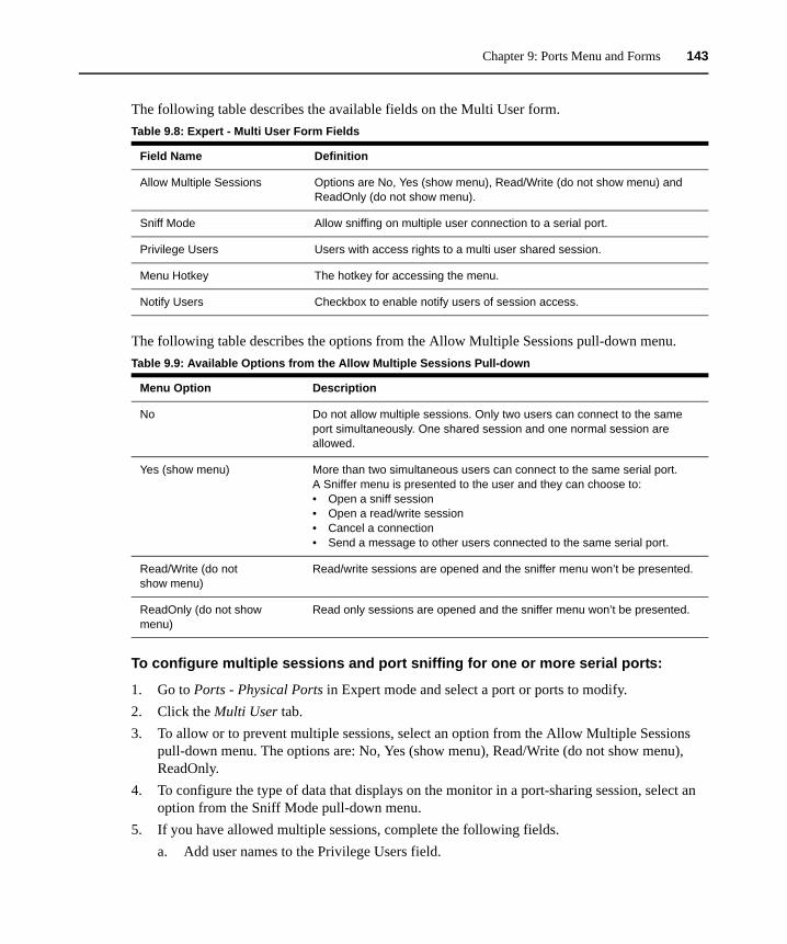
Chapter 9: Ports Menu and Forms 143
The following table describes the available fields on the Multi User form.
The following table describes the options from the Allow Multiple Sessions pull-down menu.
To configure multiple sessions and port sniffing for one or more serial ports:
1. Go to Ports - Physical Ports in Expert mode and select a port or ports to modify.2. Click the Multi User tab.3. To allow or to prevent multiple sessions, select an option from the Allow Multiple Sessions
pull-down menu. The options are: No, Yes (show menu), Read/Write (do not show menu), ReadOnly.
4. To configure the type of data that displays on the monitor in a port-sharing session, select an option from the Sniff Mode pull-down menu.
5. If you have allowed multiple sessions, complete the following fields.a. Add user names to the Privilege Users field.
Table 9.8: Expert - Multi User Form Fields
Field Name Definition
Allow Multiple Sessions Options are No, Yes (show menu), Read/Write (do not show menu) and ReadOnly (do not show menu).
Sniff Mode Allow sniffing on multiple user connection to a serial port.
Privilege Users Users with access rights to a multi user shared session.
Menu Hotkey The hotkey for accessing the menu.
Notify Users Checkbox to enable notify users of session access.
Table 9.9: Available Options from the Allow Multiple Sessions Pull-down
Menu Option Description
No Do not allow multiple sessions. Only two users can connect to the same port simultaneously. One shared session and one normal session are allowed.
Yes (show menu) More than two simultaneous users can connect to the same serial port.A Sniffer menu is presented to the user and they can choose to:• Open a sniff session• Open a read/write session• Cancel a connection• Send a message to other users connected to the same serial port.
Read/Write (do not show menu)
Read/write sessions are opened and the sniffer menu won’t be presented.
ReadOnly (do not show menu)
Read only sessions are opened and the sniffer menu won’t be presented.
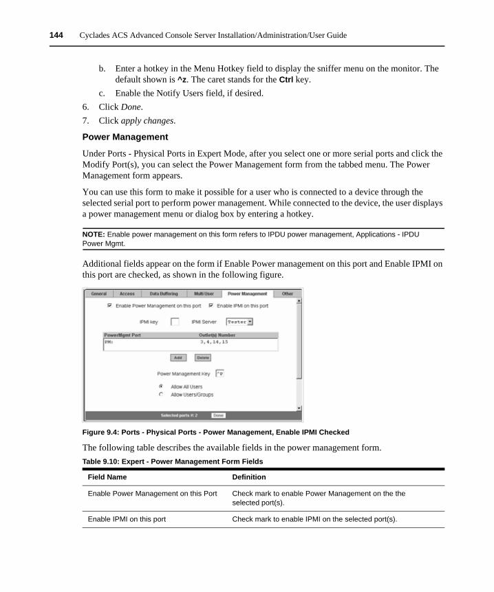
144 Cyclades ACS Advanced Console Server Installation/Administration/User Guide
b. Enter a hotkey in the Menu Hotkey field to display the sniffer menu on the monitor. The default shown is ^z. The caret stands for the Ctrl key.
c. Enable the Notify Users field, if desired.6. Click Done.7. Click apply changes.
Power Management
Under Ports - Physical Ports in Expert Mode, after you select one or more serial ports and click the Modify Port(s), you can select the Power Management form from the tabbed menu. The Power Management form appears.
You can use this form to make it possible for a user who is connected to a device through the selected serial port to perform power management. While connected to the device, the user displays a power management menu or dialog box by entering a hotkey.
NOTE: Enable power management on this form refers to IPDU power management, Applications - IPDU Power Mgmt.
Additional fields appear on the form if Enable Power management on this port and Enable IPMI on this port are checked, as shown in the following figure.
Figure 9.4: Ports - Physical Ports - Power Management, Enable IPMI Checked
The following table describes the available fields in the power management form. Table 9.10: Expert - Power Management Form Fields
Field Name Definition
Enable Power Management on this Port Check mark to enable Power Management on the the selected port(s).
Enable IPMI on this port Check mark to enable IPMI on the selected port(s).
Chapter 9: Ports Menu and Forms 145
Power management while connected to a port is possible only when one or both of the following conditions are true.
• The device connected to the console server is plugged into an IPDU and is configured for power management.
• The device connected to the console server is a server with an IPMI controller and the server is added to the IPMI device list. To see the list of previously configured IPMI devices or to add a new IPMI device, go to Applications - IPMI Power Mgmt.
If you click Enable power management and click the Add button, the Add Outlet dialog box appears. In this dialog box, you can specify the IPDU and the outlet number(s) into which the device is plugged.
The PM on the Power Management Alias pull-down menu in the example figure indicates that a serial port is configured for power management and an IPDU is connected to the configured port. Separate outlet numbers with commas, as in 1,2,3,4.
IPMI Key (available only if IPMI is enabled)
The key sequence which the authorized user(s) can use to perform IPMI power management.The default for IPMI power management is Ctrl+Shift+i (^I).
IPMI Server (available only if IPMI is enabled)
Select the device configured for IPMI power management.
PowerMgmt Port View listbox for the PM enabled ports and the assigned outlet numbers.
Power Management Key The key sequence which the authorized user(s) can use to perform power management.The default for IPDU power management is Ctrl+p (^p).
Allow All Users Radio button to allow all users to perform power management on the configured port.
Allow Users/Groups Radio button to allow only selected users or groups to perform power management on the configured port.
New User/Group (available only if Allow Users/Groups radio button is selected)
Entry field to add a new user/group.
Allowed Users/Groups (available only if Allow Users/Groups radio button is selected)
View list box of authorized users or groups.
Table 9.10: Expert - Power Management Form Fields (Continued)
Field Name Definition
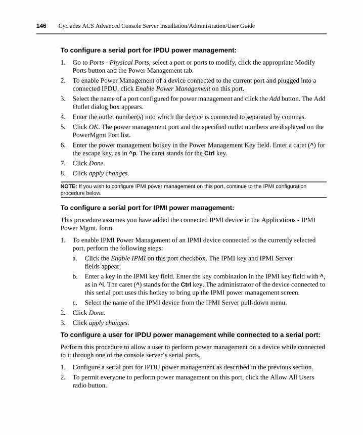
146 Cyclades ACS Advanced Console Server Installation/Administration/User Guide
To configure a serial port for IPDU power management:
1. Go to Ports - Physical Ports, select a port or ports to modify, click the appropriate Modify Ports button and the Power Management tab.
2. To enable Power Management of a device connected to the current port and plugged into a connected IPDU, click Enable Power Management on this port.
3. Select the name of a port configured for power management and click the Add button. The Add Outlet dialog box appears.
4. Enter the outlet number(s) into which the device is connected to separated by commas.5. Click OK. The power management port and the specified outlet numbers are displayed on the
PowerMgmt Port list.6. Enter the power management hotkey in the Power Management Key field. Enter a caret (^) for
the escape key, as in ^p. The caret stands for the Ctrl key.7. Click Done.8. Click apply changes.
NOTE: If you wish to configure IPMI power management on this port, continue to the IPMI configuration procedure below.
To configure a serial port for IPMI power management:
This procedure assumes you have added the connected IPMI device in the Applications - IPMI Power Mgmt. form.
1. To enable IPMI Power Management of an IPMI device connected to the currently selected port, perform the following steps: a. Click the Enable IPMI on this port checkbox. The IPMI key and IPMI Server
fields appear.b. Enter a key in the IPMI key field. Enter the key combination in the IPMI key field with ^,
as in ^i. The caret (^) stands for the Ctrl key. The administrator of the device connected to this serial port uses this hotkey to bring up the IPMI power management screen.
c. Select the name of the IPMI device from the IPMI Server pull-down menu.2. Click Done.3. Click apply changes.
To configure a user for IPDU power management while connected to a serial port:
Perform this procedure to allow a user to perform power management on a device while connected to it through one of the console server’s serial ports.
1. Configure a serial port for IPDU power management as described in the previous section.2. To permit everyone to perform power management on this port, click the Allow All Users
radio button.
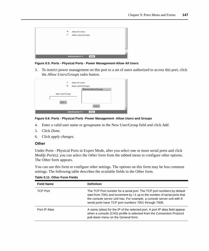
Chapter 9: Ports Menu and Forms 147
Figure 9.5: Ports - Physical Ports - Power Management-Allow All Users
3. To restrict power management on this port to a set of users authorized to access this port, click the Allow Users/Groups radio button.
Figure 9.6: Ports - Physical Ports -Power Management -Allow Users and Groups
4. Enter a valid user name or groupname in the New User/Group field and click Add.5. Click Done.6. Click apply changes.
Other
Under Ports - Physical Ports in Expert Mode, after you select one or more serial ports and click Modify Port(s), you can select the Other form from the tabbed menu to configure other options. The Other form appears.
You can use this form to configure other settings. The options on this form may be less common settings. The following table describes the available fields in the Other form. Table 9.11: Other Form Fields
Field Name Definition
TCP Port The TCP Port number for a serial port. The TCP port numbers by default start from 7001 and increment by +1 up to the number of serial ports that the console server unit has. For example, a console server unit with 8 serial ports have TCP port numbers 7001 through 7008.
Port IP Alias A name (alias) for the IP of the selected port. A port IP alias field appear when a console (CAS) profile is selected from the Connection Protocol pull-down menu on the General form.
148 Cyclades ACS Advanced Console Server Installation/Administration/User Guide
To configure TCP port number, STTY options, break interval and the login banner for a serial port connected to a console:
1. Go to Ports - Physical Ports in Expert mode and select a port or ports to modify.2. Select Modify Selected Port(s).3. Select the Other tab.4. To change the port number for the serial port, enter another number in the TCP Port field.5. To assign a name to the port’s IP address, enter an alias in the Port IP Alias field (console
connection protocol only).6. If connecting to a Microsoft Windows Server 2003 operating system through the Emergency
Management Services (EMS) console, enable the Windows EMS console connection protocol only.
7. To change the Keep-Alive interval, enter another number in the TCP Keep Alive Interval field.8. To change the idle timeout interval, enter another value in the Idle Timeout field.9. Specify stty options, if desired, in the STTY Options field.10. To change the break interval, enter a new number in the Break Interval field. 11. To change the break sequence, enter a new sequence in the Break Sequence field.
Windows EMS Checkbox to enable Windows EMS (Emergency Management Services). Appears only when a console (CAS) profile is selected from the Connection Protocol pull-down menu on the General form.
TCP Keep-Alive Interval Specifies the time interval between the periodic polling by the system to check client processes and connectivity.
Idle Timeout The maximum time (in seconds) that a session can be idle before the user is logged off.
STTY Options Set terminal options.
Break Interval Usually 250 to 500 milliseconds. It’s a logical zero on the TXD or RXD lines to reset the communications line.
Break Sequence Usually a character sequence ~break (Ctrl-b)
Login Banner Enter the text you wish to appear as a login banner when logging into a terminal.
Host to Connect This field should be populated with the IP address of the device you are connecting to. The field is displayed when a terminal server (TS) profile is selected from the Connection Protocol pull-down menu on the General form.
Terminal Type Select the desired terminal server profile from the drop-down menu.
Table 9.11: Other Form Fields (Continued)
Field Name Definition

Chapter 9: Ports Menu and Forms 149
12. To change the content of the login banner, enter new content in the Login Banner field.13. Click Done.14. Click apply changes.
To configure terminal server connection options:
Perform this procedure if you have connected a server terminal to a serial port.
1. Select the port and choose a TS profile from the Connection Protocol pull-down menu on General form.
2. Click the Other tab. The Other form displays.3. To change the port number used to access the serial port, enter another number in the TCP Port
field.4. To change the Keep Alive interval, enter another number in the TCP Keep Alive Interval field.5. To change the idle timeout interval, enter another value in the Idle Timeout field.6. Specify stty options, if desired, in the STTY Options field.7. To change the break interval, enter a new number in the Break Interval field. 8. To change the break sequence, enter a new sequence in the Break Sequence field.9. To change the content of the login banner, enter new text in the Login Banner field.10. For a dedicated terminal, enter the IP address of the desired host in the Host to Connect field.11. Enter the type of terminal in the Terminal Type field.12. Click Done.13. Click apply changes.
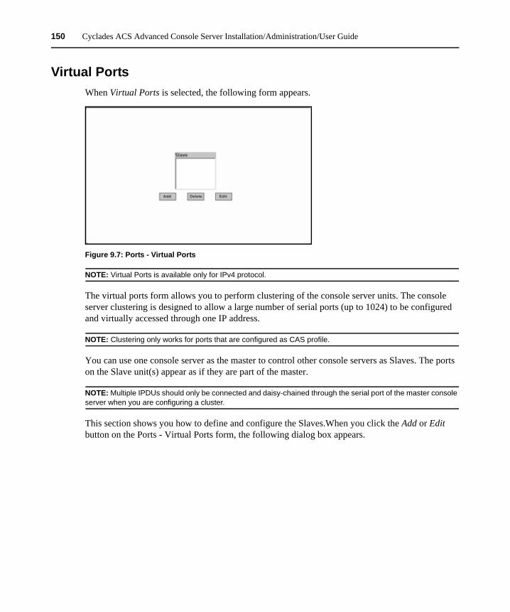
150 Cyclades ACS Advanced Console Server Installation/Administration/User Guide
Virtual PortsWhen Virtual Ports is selected, the following form appears.
Figure 9.7: Ports - Virtual Ports
NOTE: Virtual Ports is available only for IPv4 protocol.
The virtual ports form allows you to perform clustering of the console server units. The console server clustering is designed to allow a large number of serial ports (up to 1024) to be configured and virtually accessed through one IP address.
NOTE: Clustering only works for ports that are configured as CAS profile.
You can use one console server as the master to control other console servers as Slaves. The ports on the Slave unit(s) appear as if they are part of the master.
NOTE: Multiple IPDUs should only be connected and daisy-chained through the serial port of the master console server when you are configuring a cluster.
This section shows you how to define and configure the Slaves.When you click the Add or Edit button on the Ports - Virtual Ports form, the following dialog box appears.
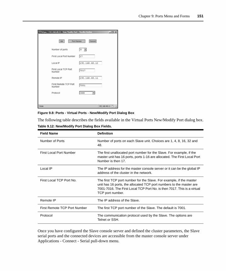
Chapter 9: Ports Menu and Forms 151
Figure 9.8: Ports - Virtual Ports - New/Modify Port Dialog Box
The following table describes the fields available in the Virtual Ports New/Modify Port dialog box.
Once you have configured the Slave console server and defined the cluster parameters, the Slave serial ports and the connected devices are accessible from the master console server under Applications - Connect - Serial pull-down menu.
Table 9.12: New/Modify Port Dialog Box Fields.
Field Name Definition
Number of Ports Number of ports on each Slave unit. Choices are 1, 4, 8, 16, 32 and 48.
First Local Port Number The first unallocated port number for the Slave. For example, if the master unit has 16 ports, ports 1-16 are allocated. The First Local Port Number is then 17.
Local IP The IP address for the master console server or it can be the global IP address of the cluster in the network.
First Local TCP Port No. The first TCP port number for the Slave. For example, if the master unit has 16 ports, the allocated TCP port numbers to the master are 7001-7016. The First Local TCP Port No. is then 7017. This is a virtual TCP port number.
Remote IP The IP address of the Slave.
First Remote TCP Port Number The first TCP port number of the Slave. The default is 7001.
Protocol The communication protocol used by the Slave. The options are Telnet or SSH.
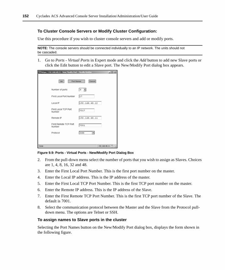
152 Cyclades ACS Advanced Console Server Installation/Administration/User Guide
To Cluster Console Servers or Modify Cluster Configuration:
Use this procedure if you wish to cluster console servers and add or modify ports.
NOTE: The console servers should be connected individually to an IP network. The units should not be cascaded.
1. Go to Ports - Virtual Ports in Expert mode and click the Add button to add new Slave ports or click the Edit button to edit a Slave port. The New/Modify Port dialog box appears.
Figure 9.9: Ports - Virtual Ports - New/Modify Port Dialog Box
2. From the pull-down menu select the number of ports that you wish to assign as Slaves. Choices are 1, 4, 8, 16, 32 and 48.
3. Enter the First Local Port Number. This is the first port number on the master. 4. Enter the Local IP address. This is the IP address of the master.5. Enter the First Local TCP Port Number. This is the first TCP port number on the master. 6. Enter the Remote IP address. This is the IP address of the Slave.7. Enter the First Remote TCP Port Number. This is the first TCP port number of the Slave. The
default is 7001.8. Select the communication protocol between the Master and the Slave from the Protocol pull-
down menu. The options are Telnet or SSH.
To assign names to Slave ports in the cluster
Selecting the Port Names button on the New/Modify Port dialog box, displays the form shown in the following figure.
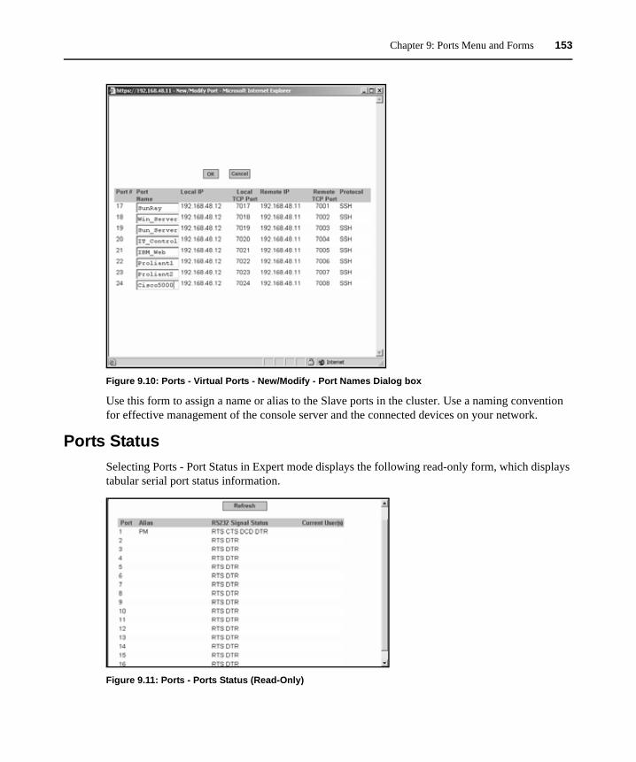
Chapter 9: Ports Menu and Forms 153
Figure 9.10: Ports - Virtual Ports - New/Modify - Port Names Dialog box
Use this form to assign a name or alias to the Slave ports in the cluster. Use a naming convention for effective management of the console server and the connected devices on your network.
Ports StatusSelecting Ports - Port Status in Expert mode displays the following read-only form, which displays tabular serial port status information.
Figure 9.11: Ports - Ports Status (Read-Only)
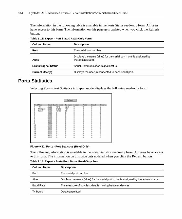
154 Cyclades ACS Advanced Console Server Installation/Administration/User Guide
The information in the following table is available in the Ports Status read-only form. All users have access to this form. The information on this page gets updated when you click the Refresh button.
Ports StatisticsSelecting Ports - Port Statistics in Expert mode, displays the following read-only form.
Figure 9.12: Ports - Port Statistics (Read-Only)
The following information is available in the Ports Statistics read-only form. All users have access to this form. The information on this page gets updated when you click the Refresh button.
Table 9.13: Expert - Port Status Read-Only Form
Column Name Description
Port The serial port number.
AliasDisplays the name (alias) for the serial port if one is assigned by the administrator.
RS232 Signal Status Serial Communication Signal Status
Current User(s) Displays the user(s) connected to each serial port.
Table 9.14: Expert - Ports-Port Status Read-Only Form
Column Name Description
Port The serial port number.
Alias Displays the name (alias) for the serial port if one is assigned by the administrator.
Baud Rate The measure of how fast data is moving between devices.
Tx Bytes Data transmitted.
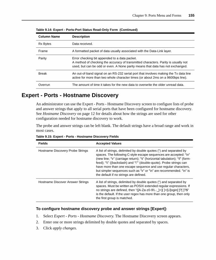
Chapter 9: Ports Menu and Forms 155
Expert - Ports - Hostname DiscoveryAn administrator can use the Expert - Ports - Hostname Discovery screen to configure lists of probe and answer strings that apply to all serial ports that have been configured for hostname discovery. See Hostname Discovery on page 12 for details about how the strings are used for other configuration needed for hostname discovery to work.
The probe and answer strings can be left blank. The default strings have a broad range and work in most cases.
To configure hostname discovery probe and answer strings [Expert]:
1. Select Expert - Ports - Hostname Discovery. The Hostname Discovery screen appears.2. Enter one or more strings delimited by double quotes and separated by spaces.3. Click apply changes.
Rx Bytes Data received.
Frame A formatted packet of data usually associated with the Data-Link layer.
Parity Error checking bit appended to a data packet.A method of checking the accuracy of transmitted characters. Parity is usually not used, but can be odd or even. A None parity means that data has not exchanged.
Break An out-of-band signal on an RS-232 serial port that involves making the Tx data line active for more than two whole character times (or about 2ms on a 9600bps line).
Overrun The amount of time it takes for the new data to overwrite the older unread data.
Table 9.14: Expert - Ports-Port Status Read-Only Form (Continued)
Column Name Description
Table 9.15: Expert - Ports - Hostname Discovery Fields
Fields Accepted Values
Hostname Discovery Probe Strings A list of strings, delimited by double quotes (“) and separated by spaces. The following C-style escape sequences are accepted: “\n” (new line; “\r” (carriage return); “\t” (horizontal tabulation); “\f” (form-feed); “\\” ((backslash) and “\”” (double-quote). Probe strings can have more than one escape sequence and use regular characters, but simpler sequences such as “\r” or “\n” are recommended. “\n” is the default if no strings are defined.
Hostname Discover Answer Strings A list of strings, delimited by double quotes (“) and separated by spaces. Must be written as POSIX extended regular expressions. If no strings are defined, then “([A-Za-z0-9\\.-_]+)[ ]+[Ll]ogin[:]?[ ]?$” is the default. If the user regex has more than one group, then only the first group is matched.

156 Cyclades ACS Advanced Console Server Installation/Administration/User Guide
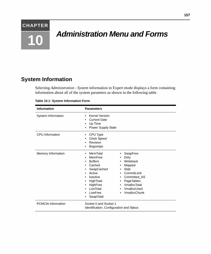
157
CHAPTER
10 Administration Menu and Forms
System InformationSelecting Administration - System information in Expert mode displays a form containing information about all of the system paramters as shown in the following table.
Table 10.1: System Information Form
Information Parameters
System Information • Kernel Version• Current Date• Up Time• Power Supply State
CPU Information • CPU Type• Clock Speed• Revision• Bogomips
Memory Information • MemTotal• MemFree• Buffers• Cached• SwapCached• Active• Inactive• HighTotal• HighFree• LowTotal• LowFree• SwapTotal
• SwapFree• Dirty• Writeback• Mapped• Slab• CommitLimit• Committed_AS• PageTables• VmallocTotal• VmallocUsed• VmallocChunk
PCMCIA Information Socket 0 and Socket 1 Identification, Configuration and Status
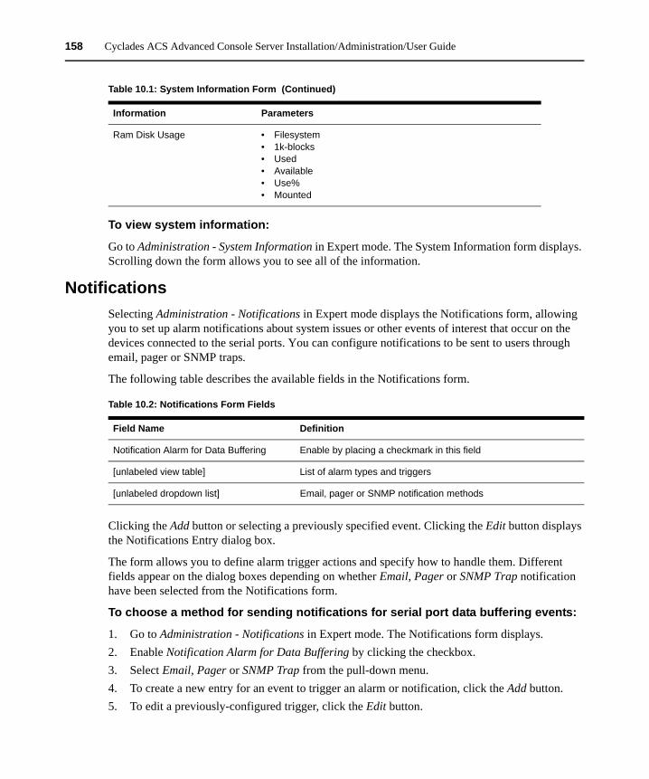
158 Cyclades ACS Advanced Console Server Installation/Administration/User Guide
To view system information:
Go to Administration - System Information in Expert mode. The System Information form displays. Scrolling down the form allows you to see all of the information.
NotificationsSelecting Administration - Notifications in Expert mode displays the Notifications form, allowing you to set up alarm notifications about system issues or other events of interest that occur on the devices connected to the serial ports. You can configure notifications to be sent to users through email, pager or SNMP traps.
The following table describes the available fields in the Notifications form.
Clicking the Add button or selecting a previously specified event. Clicking the Edit button displays the Notifications Entry dialog box.
The form allows you to define alarm trigger actions and specify how to handle them. Different fields appear on the dialog boxes depending on whether Email, Pager or SNMP Trap notification have been selected from the Notifications form.
To choose a method for sending notifications for serial port data buffering events:
1. Go to Administration - Notifications in Expert mode. The Notifications form displays.2. Enable Notification Alarm for Data Buffering by clicking the checkbox.3. Select Email, Pager or SNMP Trap from the pull-down menu.4. To create a new entry for an event to trigger an alarm or notification, click the Add button.5. To edit a previously-configured trigger, click the Edit button.
Ram Disk Usage • Filesystem• 1k-blocks• Used• Available• Use%• Mounted
Table 10.1: System Information Form (Continued)
Information Parameters
Table 10.2: Notifications Form Fields
Field Name Definition
Notification Alarm for Data Buffering Enable by placing a checkmark in this field
[unlabeled view table] List of alarm types and triggers
[unlabeled dropdown list] Email, pager or SNMP notification methods
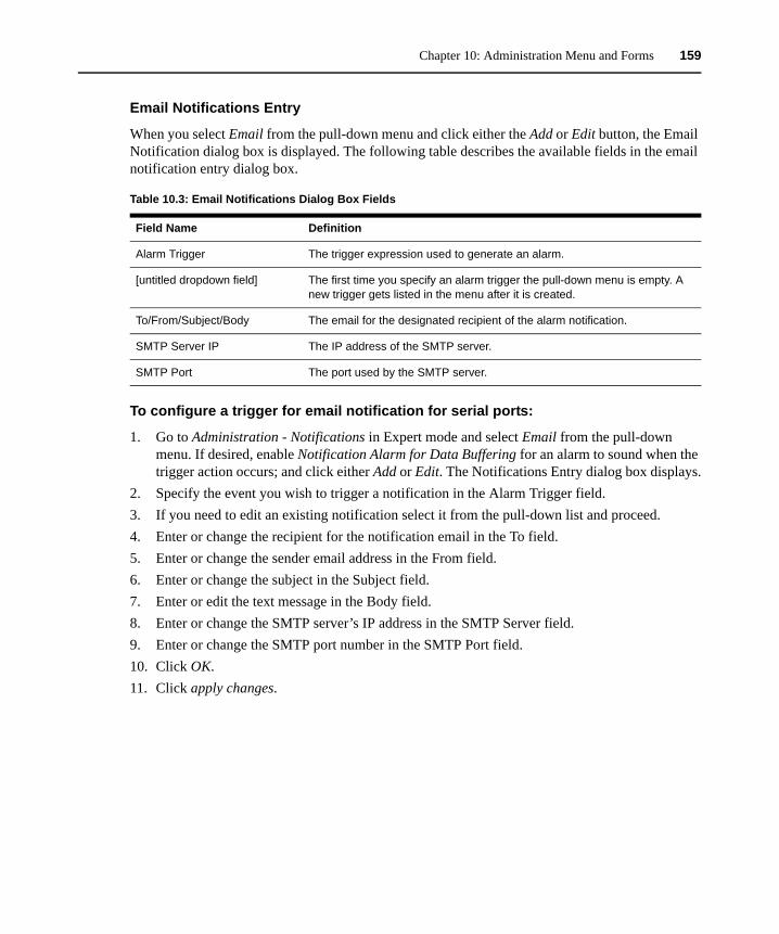
Chapter 10: Administration Menu and Forms 159
Email Notifications Entry
When you select Email from the pull-down menu and click either the Add or Edit button, the Email Notification dialog box is displayed. The following table describes the available fields in the email notification entry dialog box.
To configure a trigger for email notification for serial ports:
1. Go to Administration - Notifications in Expert mode and select Email from the pull-down menu. If desired, enable Notification Alarm for Data Buffering for an alarm to sound when the trigger action occurs; and click either Add or Edit. The Notifications Entry dialog box displays.
2. Specify the event you wish to trigger a notification in the Alarm Trigger field.3. If you need to edit an existing notification select it from the pull-down list and proceed.4. Enter or change the recipient for the notification email in the To field.5. Enter or change the sender email address in the From field.6. Enter or change the subject in the Subject field.7. Enter or edit the text message in the Body field.8. Enter or change the SMTP server’s IP address in the SMTP Server field.9. Enter or change the SMTP port number in the SMTP Port field.10. Click OK.11. Click apply changes.
Table 10.3: Email Notifications Dialog Box Fields
Field Name Definition
Alarm Trigger The trigger expression used to generate an alarm.
[untitled dropdown field] The first time you specify an alarm trigger the pull-down menu is empty. A new trigger gets listed in the menu after it is created.
To/From/Subject/Body The email for the designated recipient of the alarm notification.
SMTP Server IP The IP address of the SMTP server.
SMTP Port The port used by the SMTP server.
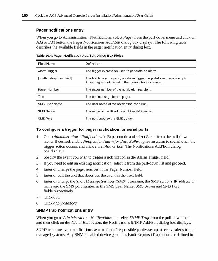
160 Cyclades ACS Advanced Console Server Installation/Administration/User Guide
Pager notifications entry
When you go to Administration - Notifications, select Pager from the pull-down menu and click on Add or Edit button the Pager Notifications Add/Edit dialog box displays. The following table describes the available fields in the pager notification entry dialog box.
To configure a trigger for pager notification for serial ports:
1. Go to Administration - Notifications in Expert mode and select Pager from the pull-down menu. If desired, enable Notification Alarm for Data Buffering for an alarm to sound when the trigger action occurs; and click either Add or Edit. The Notifications Add/Edit dialog box displays.
2. Specify the event you wish to trigger a notification in the Alarm Trigger field.3. If you need to edit an existing notification, select it from the pull-down list and proceed.4. Enter or change the pager number in the Pager Number field.5. Enter or edit the text that describes the event in the Text field.6. Enter or change the Short Message Services (SMS) username, the SMS server’s IP address or
name and the SMS port number in the SMS User Name, SMS Server and SMS Port fields respectively.
7. Click OK.8. Click apply changes.
SNMP trap notifications entry
When you go to Administration - Notifications and select SNMP Trap from the pull-down menu and then click on the Add or Edit button, the Notifications SNMP Add/Edit dialog box displays.
SNMP traps are event notifications sent to a list of responsible parties set up to receive alerts for the managed systems. Any SNMP enabled device generates Fault Reports (Traps) that are defined in
Table 10.4: Pager Notification Add/Edit Dialog Box Fields
Field Name Definition
Alarm Trigger The trigger expression used to generate an alarm.
[untitled dropdown field] The first time you specify an alarm trigger the pull-down menu is empty. A new trigger gets listed in the menu after it is created.
Pager Number The pager number of the notification recipient.
Text The text message for the pager.
SMS User Name The user name of the notification recipient.
SMS Server The name or the IP address of the SMS server.
SMS Port The port used by the SMS server.
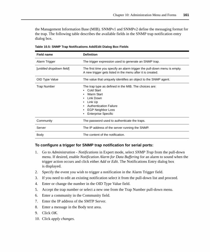
Chapter 10: Administration Menu and Forms 161
the Management Information Base (MIB). SNMPv1 and SNMPv2 define the messaging format for the trap. The following table describes the available fields in the SNMP trap notification entry dialog box.
To configure a trigger for SNMP trap notification for serial ports:
1. Go to Administration - Notifications in Expert mode, select SNMP Trap from the pull-down menu. If desired, enable Notification Alarm for Data Buffering for an alarm to sound when the trigger action occurs and click either Add or Edit. The Notifications Entry dialog box is displayed.
2. Specify the event you wish to trigger a notification in the Alarm Trigger field.3. If you need to edit an existing notification select it from the pull-down list and proceed.4. Enter or change the number in the OID Type Value field.5. Accept the trap number or select a new one from the Trap Number pull-down menu.6. Enter a community in the Community field.7. Enter the IP address of the SMTP Server.8. Enter a message in the Body text area.9. Click OK.10. Click apply changes.
Table 10.5: SNMP Trap Notifications Add/Edit Dialog Box Fields
Field name Definition
Alarm Trigger The trigger expression used to generate an SNMP trap.
[untitled dropdown field] The first time you specify an alarm trigger the pull-down menu is empty. A new trigger gets listed in the menu after it is created.
OID Type Value The value that uniquely identifies an object to the SNMP agent.
Trap Number The trap type as defined in the MIB. The choices are:• Cold Start• Warm Start• Link Down• Link Up• Authentication Failure• EGP Neighbor Loss• Enterprise Specific
Community The password used to authenticate the traps.
Server The IP address of the server running the SNMP.
Body The content of the notification.
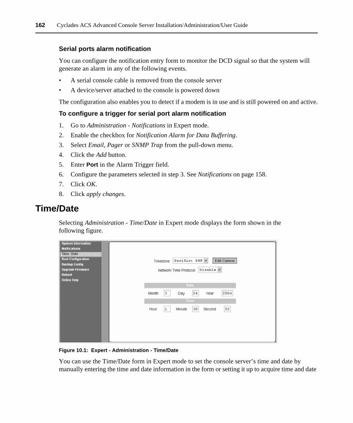
162 Cyclades ACS Advanced Console Server Installation/Administration/User Guide
Serial ports alarm notification
You can configure the notification entry form to monitor the DCD signal so that the system will generate an alarm in any of the following events.
• A serial console cable is removed from the console server• A device/server attached to the console is powered down
The configuration also enables you to detect if a modem is in use and is still powered on and active.
To configure a trigger for serial port alarm notification
1. Go to Administration - Notifications in Expert mode.2. Enable the checkbox for Notification Alarm for Data Buffering.3. Select Email, Pager or SNMP Trap from the pull-down menu.4. Click the Add button.5. Enter Port in the Alarm Trigger field.6. Configure the parameters selected in step 3. See Notifications on page 158.7. Click OK.8. Click apply changes.
Time/DateSelecting Administration - Time/Date in Expert mode displays the form shown in the following figure.
Figure 10.1: Expert - Administration - Time/Date
You can use the Time/Date form in Expert mode to set the console server’s time and date by manually entering the time and date information in the form or setting it up to acquire time and date
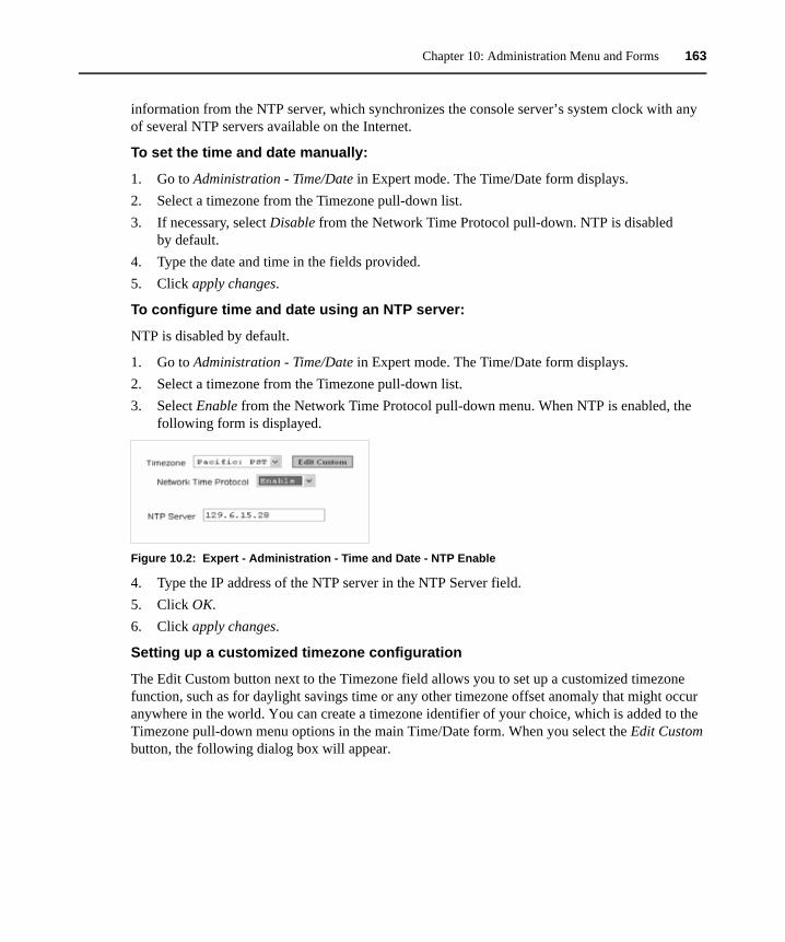
Chapter 10: Administration Menu and Forms 163
information from the NTP server, which synchronizes the console server’s system clock with any of several NTP servers available on the Internet.
To set the time and date manually:
1. Go to Administration - Time/Date in Expert mode. The Time/Date form displays. 2. Select a timezone from the Timezone pull-down list.3. If necessary, select Disable from the Network Time Protocol pull-down. NTP is disabled
by default.4. Type the date and time in the fields provided. 5. Click apply changes.
To configure time and date using an NTP server:
NTP is disabled by default.
1. Go to Administration - Time/Date in Expert mode. The Time/Date form displays.2. Select a timezone from the Timezone pull-down list.3. Select Enable from the Network Time Protocol pull-down menu. When NTP is enabled, the
following form is displayed.
Figure 10.2: Expert - Administration - Time and Date - NTP Enable
4. Type the IP address of the NTP server in the NTP Server field. 5. Click OK.6. Click apply changes.
Setting up a customized timezone configuration
The Edit Custom button next to the Timezone field allows you to set up a customized timezone function, such as for daylight savings time or any other timezone offset anomaly that might occur anywhere in the world. You can create a timezone identifier of your choice, which is added to the Timezone pull-down menu options in the main Time/Date form. When you select the Edit Custom button, the following dialog box will appear.
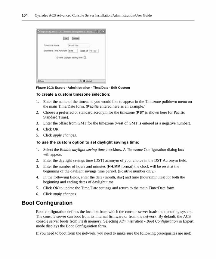
164 Cyclades ACS Advanced Console Server Installation/Administration/User Guide
Figure 10.3: Expert - Administration - Time/Date - Edit Custom
To create a custom timezone selection:
1. Enter the name of the timezone you would like to appear in the Timezone pulldown menu on the main Time/Date form. (Pacific entered here as an example.)
2. Choose a preferred or standard acronym for the timezone (PST is shown here for Pacific Standard Time).
3. Enter the offset from GMT for the timezone (west of GMT is entered as a negative number). 4. Click OK.5. Click apply changes.
To use the custom option to set daylight savings time:
1. Select the Enable daylight saving time checkbox. A Timezone Configuration dialog box will appear.
2. Enter the daylight savings time (DST) acronym of your choice in the DST Acronym field.3. Enter the number of hours and minutes (HH:MM format) the clock will be reset at the
beginning of the daylight savings time period. (Positive number only.)4. In the following fields, enter the date (month, day) and time (hours:minutes) for both the
beginning and ending dates of daylight time.5. Click OK to update the Time/Date settings and return to the main Time/Date form.6. Click apply changes.
Boot ConfigurationBoot configuration defines the location from which the console server loads the operating system. The console server can boot from its internal firmware or from the network. By default, the ACS console server boots from Flash memory. Selecting Administration - Boot Configuration in Expert mode displays the Boot Configuration form.
If you need to boot from the network, you need to make sure the following prerequisites are met:
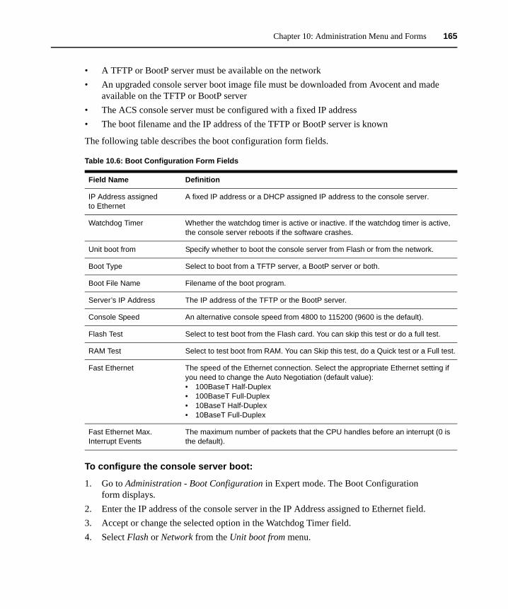
Chapter 10: Administration Menu and Forms 165
• A TFTP or BootP server must be available on the network• An upgraded console server boot image file must be downloaded from Avocent and made
available on the TFTP or BootP server• The ACS console server must be configured with a fixed IP address• The boot filename and the IP address of the TFTP or BootP server is known
The following table describes the boot configuration form fields.
To configure the console server boot:
1. Go to Administration - Boot Configuration in Expert mode. The Boot Configuration form displays.
2. Enter the IP address of the console server in the IP Address assigned to Ethernet field.3. Accept or change the selected option in the Watchdog Timer field.4. Select Flash or Network from the Unit boot from menu.
Table 10.6: Boot Configuration Form Fields
Field Name Definition
IP Address assigned to Ethernet
A fixed IP address or a DHCP assigned IP address to the console server.
Watchdog Timer Whether the watchdog timer is active or inactive. If the watchdog timer is active, the console server reboots if the software crashes.
Unit boot from Specify whether to boot the console server from Flash or from the network.
Boot Type Select to boot from a TFTP server, a BootP server or both.
Boot File Name Filename of the boot program.
Server’s IP Address The IP address of the TFTP or the BootP server.
Console Speed An alternative console speed from 4800 to 115200 (9600 is the default).
Flash Test Select to test boot from the Flash card. You can skip this test or do a full test.
RAM Test Select to test boot from RAM. You can Skip this test, do a Quick test or a Full test.
Fast Ethernet The speed of the Ethernet connection. Select the appropriate Ethernet setting if you need to change the Auto Negotiation (default value):• 100BaseT Half-Duplex• 100BaseT Full-Duplex• 10BaseT Half-Duplex• 10BaseT Full-Duplex
Fast Ethernet Max. Interrupt Events
The maximum number of packets that the CPU handles before an interrupt (0 is the default).
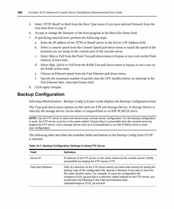
166 Cyclades ACS Advanced Console Server Installation/Administration/User Guide
5. Select TFTP, BootP or Both from the Boot Type menu if you have selected Network from the Unit boot from in step 4.
6. Accept or change the filename of the boot program in the Boot File Name field. 7. If specifying network boot, perform the following steps:
a. Enter the IP address of the TFTP or BootP server in the Server’s IP Address field.b. Select a console speed from the Console Speed pull-down menu to match the speed of the
terminal you are using on the console port of the console server.c. Select Skip or Full from the Flash Test pull-down menu to bypass or run a test on the Flash
memory at boot time.d. Select Skip, Quick or Full from the RAM Test pull-down menu to bypass or run a test on
the RAM at boot time.e. Choose an Ethernet speed from the Fast Ethernet pull-down menu.f. Specify the maximum number of packets that the CPU handles before an interrupt in the
Fast Ethernet Max. Interrupt Events field.8. Click apply changes.
Backup ConfigurationSelecting Administration - Backup Config in Expert mode displays the Backup Configuration form.
The Type pull-down menu options on this form are FTP and Storage Device. If Storage Device is selected, the storage device can be either a CompactFlash or an IDE PCMCIA drive.
NOTE: Use an FTP server to save and retrieve your console server configuration. For the backup configuration to work, the FTP server must be on the same subnet. Ensure that it is accessible from the console server by pinging the FTP server. Use a storage device such as a CompactFlash or an IDE PCMCIA drive to save your configuration.
The following table describes the available fields and buttons in the Backup Config form if FTP is selected.
Table 10.7: Backup Configuration Settings if Using FTP Server
Field Definition
Server IP IP address of an FTP server on the same subnet as the console server. (Verify accessibility by pinging the FTP server.) FTP
Path and Filename Path of a directory on the FTP server where you have write access for saving the backup copy of the configuration file. Specify a filename if you wish to save the file under another name. For example, to save the configuration file zvmppccs.0720_qa.acs-k26 in a directory called /upload on the FTP server, you would enter the following in the Path and Filename field: /upload/zvmppccs.0720_qa.acs-k26
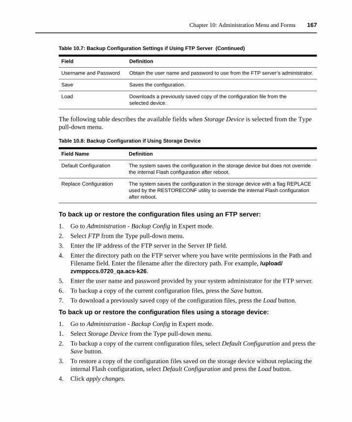
Chapter 10: Administration Menu and Forms 167
The following table describes the available fields when Storage Device is selected from the Type pull-down menu.
To back up or restore the configuration files using an FTP server:
1. Go to Administration - Backup Config in Expert mode.2. Select FTP from the Type pull-down menu.3. Enter the IP address of the FTP server in the Server IP field.4. Enter the directory path on the FTP server where you have write permissions in the Path and
Filename field. Enter the filename after the directory path. For example, /upload/zvmppccs.0720_qa.acs-k26.
5. Enter the user name and password provided by your system administrator for the FTP server.6. To backup a copy of the current configuration files, press the Save button. 7. To download a previously saved copy of the configuration files, press the Load button.
To back up or restore the configuration files using a storage device:
1. Go to Administration - Backup Config in Expert mode.1. Select Storage Device from the Type pull-down menu.2. To backup a copy of the current configuration files, select Default Configuration and press the
Save button.3. To restore a copy of the configuration files saved on the storage device without replacing the
internal Flash configuration, select Default Configuration and press the Load button.4. Click apply changes.
Username and Password Obtain the user name and password to use from the FTP server’s administrator.
Save Saves the configuration.
Load Downloads a previously saved copy of the configuration file from the selected device.
Table 10.8: Backup Configuration if Using Storage Device
Field Name Definition
Default Configuration The system saves the configuration in the storage device but does not override the internal Flash configuration after reboot.
Replace Configuration The system saves the configuration in the storage device with a flag REPLACE used by the RESTORECONF utility to override the internal Flash configuration after reboot.
Table 10.7: Backup Configuration Settings if Using FTP Server (Continued)
Field Definition
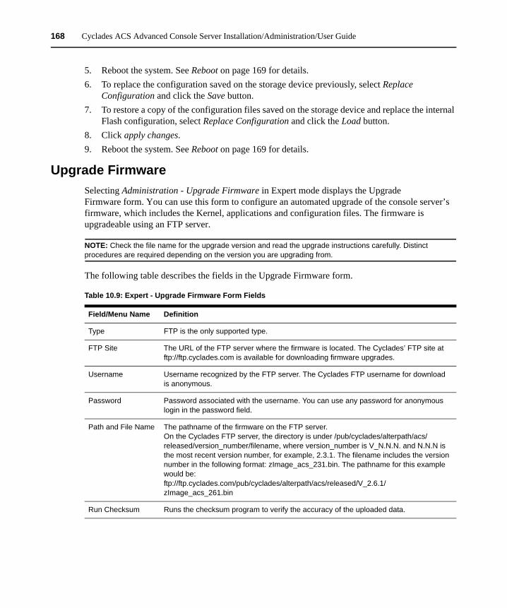
168 Cyclades ACS Advanced Console Server Installation/Administration/User Guide
5. Reboot the system. See Reboot on page 169 for details.6. To replace the configuration saved on the storage device previously, select Replace
Configuration and click the Save button.7. To restore a copy of the configuration files saved on the storage device and replace the internal
Flash configuration, select Replace Configuration and click the Load button.8. Click apply changes.9. Reboot the system. See Reboot on page 169 for details.
Upgrade FirmwareSelecting Administration - Upgrade Firmware in Expert mode displays the Upgrade Firmware form. You can use this form to configure an automated upgrade of the console server’s firmware, which includes the Kernel, applications and configuration files. The firmware is upgradeable using an FTP server.
NOTE: Check the file name for the upgrade version and read the upgrade instructions carefully. Distinct procedures are required depending on the version you are upgrading from.
The following table describes the fields in the Upgrade Firmware form.
Table 10.9: Expert - Upgrade Firmware Form Fields
Field/Menu Name Definition
Type FTP is the only supported type.
FTP Site The URL of the FTP server where the firmware is located. The Cyclades’ FTP site at ftp://ftp.cyclades.com is available for downloading firmware upgrades.
Username Username recognized by the FTP server. The Cyclades FTP username for download is anonymous.
Password Password associated with the username. You can use any password for anonymous login in the password field.
Path and File Name The pathname of the firmware on the FTP server. On the Cyclades FTP server, the directory is under /pub/cyclades/alterpath/acs/released/version_number/filename, where version_number is V_N.N.N. and N.N.N is the most recent version number, for example, 2.3.1. The filename includes the version number in the following format: zImage_acs_231.bin. The pathname for this example would be: ftp://ftp.cyclades.com/pub/cyclades/alterpath/acs/released/V_2.6.1/zImage_acs_261.bin
Run Checksum Runs the checksum program to verify the accuracy of the uploaded data.
Chapter 10: Administration Menu and Forms 169
To upgrade the console server firmware:
This procedure is for upgrading the latest release of the console server firmware. The upgrade installs the software on the Flash memory.
1. Go to Administration - Upgrade Firmware. The Upgrade Firmware form displays.2. Choose FTP from the Type menu. (FTP is the only supported type).3. Enter the URL of the FTP server in the FTP Site field.4. Enter the username recognized by the FTP server in the Username field. 5. Enter the password associated with the username on the FTP server in the Password field.6. Enter the pathname of the file on the FTP server in the Path and Filename field.7. Click the Upgrade Now button.8. Click cancel changes if you need to restore the backed up configuration files.
RebootSelecting Administration - Reboot in Expert mode brings up a simple form containing only a Reboot button. Clicking the Reboot button reboots the console server.
To reboot the console server:
1. Go to Administration - Reboot in Expert mode.2. Click the Reboot button. A confirmation dialog box displays.3. Click OK.
Online HelpWhen the online help feature is configured for your console server, clicking the Help button from any form on the Web Manager opens a new window and redirects its content to the configured path for the online help product documentation.
NOTE: Using the online help feature from the Avocent/Cyclades server is not always possible due to firewall configurations, nor is it recommended. It is generally advisable for you to use the online help system provided with the product or download the online help .zip file and run it from a local server.
Online help for the ACS console server is shipped with the product and should be loaded on a local server. The system administrator can also download the online help from Avocent. For more information on downloading the online help, contact Technical Support. The procedure for configuring the online help on the local server follows.
Select Administration - Online Help in Expert mode. The online help configuration page is displayed.
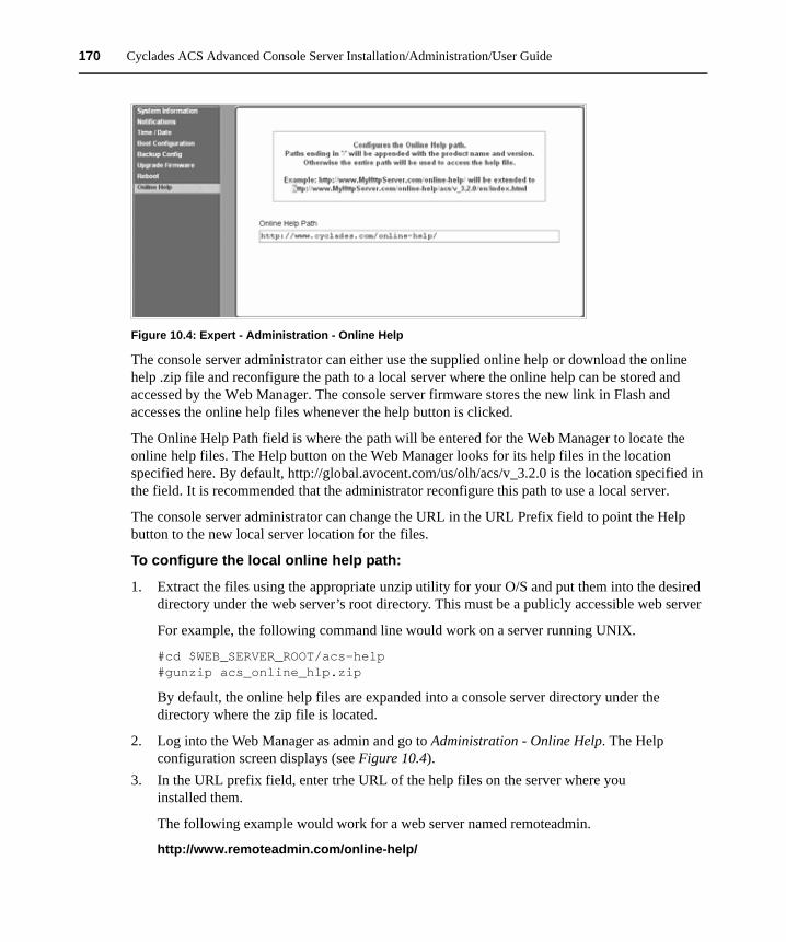
170 Cyclades ACS Advanced Console Server Installation/Administration/User Guide
Figure 10.4: Expert - Administration - Online Help
The console server administrator can either use the supplied online help or download the online help .zip file and reconfigure the path to a local server where the online help can be stored and accessed by the Web Manager. The console server firmware stores the new link in Flash and accesses the online help files whenever the help button is clicked.
The Online Help Path field is where the path will be entered for the Web Manager to locate the online help files. The Help button on the Web Manager looks for its help files in the location specified here. By default, http://global.avocent.com/us/olh/acs/v_3.2.0 is the location specified in the field. It is recommended that the administrator reconfigure this path to use a local server.
The console server administrator can change the URL in the URL Prefix field to point the Help button to the new local server location for the files.
To configure the local online help path:
1. Extract the files using the appropriate unzip utility for your O/S and put them into the desired directory under the web server’s root directory. This must be a publicly accessible web server
For example, the following command line would work on a server running UNIX.
#cd $WEB_SERVER_ROOT/acs-help #gunzip acs_online_hlp.zip
By default, the online help files are expanded into a console server directory under the directory where the zip file is located.
2. Log into the Web Manager as admin and go to Administration - Online Help. The Help configuration screen displays (see Figure 10.4).
3. In the URL prefix field, enter trhe URL of the help files on the server where you installed them.
The following example would work for a web server named remoteadmin.
http://www.remoteadmin.com/online-help/

Chapter 10: Administration Menu and Forms 171
The software adds the name of the acs directory to the URL prefix and launches the online help.
4. Click Save. 5. Click apply changes.

172 Cyclades ACS Advanced Console Server Installation/Administration/User Guide

173
AppendicesAppendix A: Technical Specifications Table A.1: ACS Console Server Product Specifications
Processing Capability
CPU MPC855T (PowerPC Dual-CPU)
Memory 128MB DIMM SDRAM / 16MB CompactFlash
User Ports
Number Ethernet 10/100BT on RJ45: 1; RS-232 console on RJ-45: 1; RS-232 serial on RJ-45 (4, 8, 16, 32, 48 depending on model); PC card slots, 2 supporting secondary Ethernet, wireless networking, CDMA, GPRS, GSM, V.90 modems and ISDN
Type RJ-45, PC card
Power
Internal 100-240VAC at 50/60 Hz
Input Types Optional dual entry, redundant power supplies, -48VDC option available
Environmental
Operating Temperature 50°F to 112°F (10°C to 44°C)
Storage Temperature -40°F to 185°F (-40°C to 85°C)
Humidity 5% to 90% non-condensing
Physical Dimensions
Single Port 6.3 x 4.0 x 1.5 in (16 x 10 x 3.8 cm)
4-48 Ports 17 x 8.5 x 1.75 in (43.18 x 21.59 x 4.45 cm)
Safety and EMC Approvals and Markings
FCC Part 15 A, ICES-003, C-Tick, VCCI Class A, BSMI Class A, MIC Class A, CE (EN55022 Class A, EN55024, EN60950-1), GS, CB, CSA/UL 60950-1, Solaris Ready™, NEBS for ACS 16 NEBS and ACS 32 NEBS with single or dual DC power supplies
APPENDICES
174 Cyclades ACS Advanced Console Server Installation/Administration/User Guide
Appendix B: Safety, Regulatory and Compliance InformationThe following safety, regulatory and compliance information for the ACS console server is described in this appendix. • Safety and environmental guidelines for rack-mounting the console server on page 174• Safety precautions for operating the console server on page 176• Sicherheitsvorkehrungen beim Betrieb des Cyclades ACS on page 176• NEBS certification on page 177• Working inside the console server on page 178• Replacing the battery on page 179• Austausch der Batterie on page 179• Remplacement de la batterie on page 179• FCC warning statement on page 179• Notice about FCC compliance for all Cyclades ACS Advanced Console Server models on page
179• Canadian DOC notice on page 180• Aviso de Precaución S-Mark Argentina on page 180• Trabajar dentro del Cyclades ACS Advanced Console Server on page 180
Safety and environmental guidelines for rack-mounting the console server
NOTE: Each heading and its contents in this section is also provided in German (Deutsch) in italics immediately following the English version.
The following considerations should be taken into account when rack-mounting the Cyclades ACS advanced console server.Folgendes sollte beim Rack-Einbau des Cyclades ACS berücksichtigt werden.
Temperature
The manufacturer's maximum recommended ambient temperature for the Cyclades ACS advanced console server is 112 ºF (44 ºC).
Temperatur
Die maximal empfohlene Umgebungstemperatur des AlterPath ACS beträgt 44ºC (112 ºF).
Elevated operating ambient temperature
If the console server is installed in a closed or multi-unit rack assembly, the operating ambient temperature of the rack environment may be greater than room ambient temperature. Therefore, consideration should be given to installing the equipment in an environment compatible with the manufacturer’s maximum rated ambient temperature. See above.
Appendices 175
Erhöhte Umgebungstemperatur im betrieb
Bitte treffen Sie entsprechende Vorkehrungen um die Herstellerangaben zur maximalen Umgebungstemperatur einzuhalten. Bitte beachten Sie, dass bei einer Installation des ACS in einem geschlossenen oder mehrfach bestücktem Rack die Umgebungstemperatur im Betrieb höher sein kann als die Raumtemperatur.
Reduced air flow
Installation of the equipment in a rack should be such that the amount of air flow required for safe operation of the equipment is not compromised.
Luftdurchsatz
Für einen sicheren Betrieb bitte auf ausreichenden Luftdurchsatz im Rack achten.
Mechanical loading
Mounting of the equipment in the rack should be such that a hazardous condition is not achieved due to uneven mechanical loading.
Sicherer mechanischer Aufbau
Bitte vermeiden Sie beim Einbau der Geräte ungleichmäßige mechanische Belastung.
Circuit overloading
Consideration should be given to the connection of the equipment to the supply circuit and the effect that overloading of circuits might have on overcurrent protection and supply wiring. Appropriate consideration of equipment nameplate ratings should be used when addressing this concern.
Elektrische Überlastung
Bitte beachten Sie beim elektrischen Anschluss der Geräte, dass diese zum Schutz vor Überlastung mit entsprechenden Schutzvorkehrungen ausgestattet sein können. Bitte sorgen Sie gegebenenfalls für Klarheit durch entsprechende Beschriftung:
Reliable earthing
Reliable earthing of rack-mounted equipment should be maintained. Particular attention should be given to supply connections other than direct connections to the branch circuit, such as power strips or extension cords.
Zuverlässige Erdung
Eine ausreichende Erdung der im Rack montierten Geräte muss sichergestellt sein. Insbesondere sollte indirekten Verbindungen zur Stromversorgung über Powerleisten oder Verlängerungen besondere Aufmerksamkeit gewidmet werden.
176 Cyclades ACS Advanced Console Server Installation/Administration/User Guide
Safety precautions for operating the console serverPlease read all the following safety guidelines to protect yourself and your Cyclades ACS advanced console server.
Sicherheitsvorkehrungen beim Betrieb des Cyclades ACSBitte lesen Sie alle folgenden Sicherheitsrichtlinien um sich und Ihren Alterpath ACS vor Schäden zu bewahren.
WARNING: Do not operate your Cyclades ACS advanced console server with the cover removed.
Vorsicht: Bitte betreiben Sie den Alterpath ACS nicht mit geöffnetem Gehäuse.
CAUTION: To avoid shorting out your Cyclades ACS advanced console server when disconnecting the network cable, first unplug the cable from the Host Server, unplug external power (if applicable) from the equipment and then unplug the cable from the network jack. When reconnecting a network cable to the back of the equipment, first plug the cable into the network jack and then into the Host Server equipment.
Vorsicht: Um Schäden beim Entfernen des Netzwerkkabels zu vermeiden bitte immer zuerst das Kabel vom Host Server entfernen, anschließend die externe Stromzufuhr abklemmen und danach das Kabel aus der Netzwerkbuchse ausstecken. Beim Wiederherstellen der Verbindung immer zuerst das Kabel in die Netzwerkbuchse des ACS zuerst einstecken und danach das Kabel in den Host Server einstecken.
CAUTION: To help prevent electric shock, plug the Cyclades ACS advanced console server into a properly grounded power source. The cable is equipped with a three-prong plug to help ensure proper grounding. Do not use adaptor plugs or remove the grounding prong from the cable. If you have to use an extension cable, use a three-wire cable with properly grounded plugs.
Vorsicht: Um Stromschläge zu vermeiden den Alterpath ACS bitte mit einer ausreichend geerdeten Stromquelle verbinden. Zu diesem Zweck ist das Eingangskabel ist mit einem dreipoligen Stecker ausgestattet. Bitte keinesfalls dazwischen liegende adaptor einsetzen oder den Erdungsstift entfernen. Falls eine Verlängerung eingesetzt werden muss bitte ausschließlich dreipolige Kabel mit ausreichender Erdung verwenden.
CAUTION: To help protect the Cyclades ACS advanced console server from electrical power fluctuations, use a surge suppressor, line conditioner or uninterruptible power supply. Be sure that nothing rests on the cables of the console server and that they are not located where they can be stepped on or tripped over. Do not spill food or liquids on console server.
Vorsicht: Um den Alterpath ACS vor elektrischen Netzschwankungen zu bewahren bitte Überspannungsfilter, Entstörfilter oder eine UVS einsetzen. Stellen Sie bitte sicher dass sich keine Gegenstände auf den Kabeln des ACS befinden und dass die Kabel tritt- und stolpersicher geführt sind. Bitte keine Lebensmittel oder Flüssigkeiten über den ACS schütten.
CAUTION: Do not push any objects through the openings of the Cyclades ACS advanced console server. Doing so can cause fire or electric shock by shorting out interior components.
Vorsicht: Zur Vermeidung von Brandgefahr oder elektrischen Schlägen bitte keine Gegenstände durch die Öffnungen des Alterpath ACS stecken.
Appendices 177
CAUTION: Keep your Cyclades ACS advanced console server away from heat sources and do not block host’s cooling vents.
Vorsicht: Der Alterpath ACS muss vor Hitzequellen geschützt werden und die Lüfterausgänge dürfen nicht blockiert sein.
CAUTION: The Cyclades ACS advanced console server DC-powered models are only intended to be installed in restricted access areas (Dedicated Equipment Rooms, Equipment Closets or the like) in accordance with Articles 110-18, 110-26 and 110-27 of the National Electrical Code, ANSI/NFPA 701, 1999 Edition. Use 18 AWG or 0.75 mm2 or above cable to connect the DC configured unit to the Centralized D.C. Power Systems. Install the required double-pole, single-throw, DC rated UL Listed circuit breaker between the power source and the Cyclades ACS advanced console server DC version. Minimum Breaker Rating: 2A. Required conductor size: 18 AWG.
Vorsicht: Die Alterpath ACS DC/Gleichstrom-Modelle sind nur für den Einsatz in Bereichen mit begrenztem Zugang vorgesehen (abgeschlossene Geräteräume oder Geräteschränke), die entsprechend den Artikeln 110-18, 110-26 und 110-27 des National Electrical Code, ANSI/NFPA 701, 1999 Edition ausgeführt sind. Zur Verbindung mit der zentralen Gleichstromversorgung bitte nur Kabel mit mindestens 18 AWG bzw. 0.75mm2 verwenden. Bitte nur freigegebene, zweipolige aber einfach auslösende und für Gleichstrom zugelassene Sicherungsautomaten einsetzen.
CAUTION: This unit has one or two power supply cords. Disconnect the power supply cord before servicing to avoid electric shock.
ATTENTION!: Cet appareil comporte un ou deux cordon d’alimentations. Afin de prévenir les choc électriques, debrancer les cordons d’alimentation avant de fairt le dépannage.
Vorsicht: Das Geraet hat entweder ein oder zwei Netzverbindungen. Um elektrischen Schlag zu vermeiden muessen die Netzverbindungen getrennt sein bevor Wartungsarbeiten vorgenommen werden.
NEBS certificationThe models ACS 16 NEBS and ACS 32 NEBS DC-powered models are NEBS Level 3 certified and are tested to meet all the requirements and objectives described in Telecordia documents GR-63-CORE: Physical Protection, which identifies the spatial and environmental criteria and GR-1089-CORE: Electromagnetic Compatibility and Electrical Safety requirements.
NOTE: Use shielded cables when connecting devices to the console and the serial ports to comply with NEBS certification requirements.
CAUTION: Observe all central office safety precautions when connecting and disconnecting the Cyclades ACS advanced console server power supplies from the DC power source. To comply with NEBS requirements, ensure that your site adheres to the environmental criteria described in the NEBS specifications.
178 Cyclades ACS Advanced Console Server Installation/Administration/User Guide
NEBS ZertifizierungDie Alterpath ACS16 und ACS32 mit DC/Gleichstromnetzteil gibt es auch in NEBS Level 3 zertifizierter Ausführung. Diese sind geprüft auf Einhaltung aller Anforderungen entsprechend Telecordia Dokument GR-63-CORE: Physikalischer Schutz, betreffend der Raum- und Umgebungsbedingungen, sowie GR-1089-CORE: Elektromagnetische Kompatibilität und Elektrische- sowie Sicherheitsanforderungen.
Anmerkung: Bitte NEBS konforme, abgeschirmte Kabel zum Anschluss von Geräten an die Konsolen- und seriellen Ports verwenden.
Vorsicht: Bitte alle Sicherheitsvorschriften des Vermittlungsamtes bei Anschluss und Abstecken der Alterpath ACS Stromversorgung von der Gleichstromquelle einhalten. Um die NEBS Anforderungen zu erfüllen bitte sicherstellen, dass sich die Umgebungsbedingungen des Einsatzortes innerhalb der Grenzen der NEBS Spezifikation bewegen.
Working inside the console serverDo not attempt to service the console server yourself, except when following instructions from Cyclades Technical Support personnel. In the latter case, first take the following precautions:1. Turn the console server off.2. Ground yourself by touching an unpainted metal surface on the back of the equipment before
touching anything inside the unit.
Electrostatic Discharge (ESD) Precautions
When handling any electronic component or assembly, you must observe the following antistatic precautions to prevent damage. • Always wear a grounded wrist strap when working around printed circuit boards,• Treat all assemblies, components and interface connections as static-sensitive,• Avoid working in carpeted areas and• Keep body movement to a minimum while removing or installing boards to minimize the
buildup of static charge.
Arbeiten am Cyclades ACSBitte versuchen Sie nicht den ACS selbst zu warten mit Ausnahme unter Befolgung der Anweisungen von Cyclades technischem Personal. In diesem Fall bitte folgenden Vorsichtsmaßnahmen einhalten:1. Schalten Sie den ACS aus.2. Erden Sie sich bitte selbst durch Berühren einer blanken Metalloberfläche auf der Rückseite
des Gerätes bevor Sie das Innere berühren
Appendices 179
Vorsichtsmassnahmen gegen Elektrostatische Entladung (ESD)
Zur Vermeidung von Beschädigungen sind bei Arbeiten an elektronischen Komponenten oder Baugruppen die folgenden Vorsichtsmaßnahmen einzuhalten.• Bitte immer ein Erdungsarmband während der Arbeit an elektronischen Platinen tragen.• Bitte alle Baugruppen, Komponenten und Steckkontakte als elektrostatisch sensitiv behandeln.• Bitte Arbeiten auf Teppichböden vermeiden und.• Zur Minimierung von elektrostatischen Aufladungen alle Körperbewegungen während Ein-
oder Ausbau von Boards auf ein Minimum reduzieren.
Replacing the battery
CAUTION: There is the danger of explosion if the battery is replaced incorrectly. Replace the battery only with the same or equivalent type recommended by the manufacturer. Dispose of used batteries according to the manufacturer's instructions.
Austausch der Batterie
Vorsicht: Bei Einsetzen einer falschen Batterie besteht Explosionsgefahr. Ersetzen Sie die Batterie nur durch den gleichen oder vom Hersteller empfohlenen Batterietyp. Entsorgen Sie die benutzten Batterien nach den Anweisungen des Herstellers.
Remplacement de la batterie
ATTENTION!: Al y a risque d’explosion si la batterie est remplacée par une batterie de type incorrect. Mettre au rebut les batteries usagées conformént aux instructions.
FCC warning statementThe Cyclades ACS advanced console server has been tested and found to comply with the limits for Class A digital devices, pursuant to Part 15 of the FCC rules. These limits are designed to provide reasonable protection against harmful interference when the equipment is operated in a commercial environment.This equipment generates, uses and can radiate radio frequency energy and, if not installed and used in accordance with the Installation and Service Manual, may cause harmful interference to radio communications. Operation of this equipment in a residential area is likely to cause harmful interference in which case the user is required to correct the problem at his or her own expense.
Notice about FCC compliance for all Cyclades ACS Advanced Console Server models
To comply with FCC standards, the Cyclades ACS advanced console server requires the use of a shielded CAT5 cable for the Ethernet interface. Notice that this cable is not supplied with either of the products and must be provided by the customer.
180 Cyclades ACS Advanced Console Server Installation/Administration/User Guide
Canadian DOC noticeThe Cyclades ACS advanced console server does not exceed the Class A limits for radio noise emissions from digital apparatus set out in the Radio Interference Regulations of the Canadian Department of Communications.L’Cyclades ACS advanced console server n’émete pas de bruits radioélectriques dépassant les limites applicables aux appareils numériques de la classe A prescrites dans le règlement sur le brouillage radioélectrique edicté par le Ministère des Communications du Canada.
Aviso de Precaución S-Mark ArgentinaPor favor de leer todos los avisos de precaución como medida preventiva para el operador y el Cyclades ACS advanced console server.
IMPORTANTE: No hacer funcionar el Cyclades ACS advanced console server con la tapa abierta.
IMPORTANTE: Para prevenir un corto circuito en el Cyclades ACS advanced console server al desconectarlo de la red, primero desconectar el cable del equipo y luego el cable que conecta a la red. Para conectar el equipo a la red, primero conectar el cable a la red y luego al equipo.
IMPORTANTE: Asegurarse que el equipo este conectado a tierra, para prevenir un shock eléctrico. El cable eléctrico del equipo viene con tres clavijas para conectar asegurar conexión a tierra. No use adaptadores o quite la clavija de tierra. Si se tiene que utilizar una extensión, utilice una que tenga tres cables con clavija para conexión a tierra. Para proteger al Cyclades ACS advanced console server de fluctuaciones en corriente eléctrica, utilice una fuente eléctrica de respaldo. Asegurarse de que nada descanse sobre los cables del Cyclades ACS advanced console server, y que los cables no obstruyan el paso. Asegurarse de no dejar caer alimentos o bebidas en el Cyclades ACS Advanced Console Server Installation, Administration and User’s Guide. Si esto ocurre, avise a Cyclades Corporation.
IMPORTANTE: No empuje ningún tipo de objeto en los compartimientos del Cyclades ACS advanced console server. Hacer esto podría ocasionar un incendio o causar un corto circuito dentro del equipo.
IMPORTANTE: Mantenga el Cyclades ACS advanced console server fuera del alcancé de calentadores, y asegurarse de no tapar la ventilación del equipo.
IMPORTANTE: El Cyclades ACS advanced console server con alimentación de corriente directa (CD) solo debe ser instalado en áreas con restricción y de acuerdo a los artículos 110-18, 110-26, y 110-27 del National Electrical Code, ANSI/NFPA 701, Edición 1999. Para conectar la corriente directa (CD) al sistema, utilice cable de 0.75 mm (18 AWG). Instalar el interruptor corriente directa (CD) aprobado por UL entre la fuente de alimentación y el Cyclades ACS advanced console server. El limite mínimo del interruptor deberá ser 2 amperes, con conductor de 0.75 mm (18 AWG).
Trabajar dentro del Cyclades ACS Advanced Console ServerNo intente dar servicio al Cyclades ACS advanced console server, solo que este bajo la dirección de Soporte Técnico de Cyclades. Si este es el caso, tome las siguientes precauciones:Apague el Cyclades ACS advanced console server. Asegurase que este tocando tierra antes de tocar cualquier otra cosa, que puede ser al tocar la parte trasera del equipo.

Appendices 181
Batería
IMPORTANTE: Una batería nueva puede explotar, si no esta instalada correctamente. Remplace la batería cuando sea necesario solo con el mismo tipo recomendado por el fabricante de la batería. Deshacerse de la batería de acuerdo a las instrucciones del fabricante de la batería.

182 Cyclades ACS Advanced Console Server Installation/Administration/User Guide
Appendix C: Technical SupportOur Technical Support staff is ready to assist you with any installation or operating issues you encounter with your Avocent product. If an issue should develop, follow the steps below for the fastest possible service.
To resolve an issue:
1. Check the pertinent section of this manual to see if the issue can be resolved by following the procedures outlined.
2. Check our web site at www.avocent.com/support to search the knowledge base or use the online service request.
3. Call the Avocent Technical Support location nearest you.

183
IndexAaccess 137
allow SSH root 38, 123SSH root 55
access requirements, port 25access server
(CAS) profile, console 131access to connected devices
configuring 9accessing ACS 2accessing the web manager, other methods of 20ACS
accessing 2administrators, common tasks for 31boot, to configure 165command line, power management from 12connect to 25firmware, to upgrade 169logins, configuring authentication for 115mounting 13packet filtering 6to reboot 169
action, boot 91active ports sessions 114add
outlet group 65terminal menu option 70users
for power management 66add rule 7
addinga group 112a user 112users 19
admin 111administering users 9administrative modes, overview of 34administrator forms, common features of 32administrators, common tasks for ACS 31alarm
notification 162notification, serial ports 162threshold 29trigger 159
alarms 8alias 154alias, port IP 147allow
multiple sessions 143SSH root access 38, 123
authentication 4, 115for ACS logins, configuring 115methods 91, 138protocols 91serial port 38, 123servers, configuring 116
authorizationraccess 117user 117
authorized users/groups 137authtype 115
INDEX
184 Cyclades ACS Advanced Console Server Installation/Administration/User Guide
Bbackup configuration 166banner, login 148basic installation procedures 13battery, replacing 179baud rate 44, 154bidirectional 133bidirectionlogin timeout 137bidirectionshell command 138boot action 91boot configuration 164boot, to configure ACS 165bootp 165break 155break interval 148break sequence 148buffer size, syslog 141buffering
data 8, 140buzzer 29, 61bytes, RX 155bytes, TX 154
Ccall back 82Canadian doc notice 180CAS
profile, console access server 131CDMA 2CDMA PCMCIA cards, configuring 88Certificate for HTTP Security 126certification, NEBS 177chain 6channel 87command line, power management 12
command, wiz 15common features of administrator forms 32common tasks for ACS administrators 31community 95, 161compact flash 81compact flash PCMCIA cards, configuring 86configuration
backup 166boot 164firewall 97outlet groups 65
configuringaccess to connected devices 9authentication for ACS logins 115authentication servers 116CDMA PCMCIA cards 88CompactFlash PCMCIA cards 86Ethernet PCMCIA cards 85GSM PCMCIA cards 84ISDN PCMCIA cards 83modem PCMCIA cards 82ports 19ports for power management 11power management 11wireless LAN PCMCIA cards 87
connect 24, 55connect to ACS 25connect to serial ports 25connect, host to 148connecting Cyclades PM IPDUs 21connection
protocol 26, 43protocol modem 133protocol power management 133protocols terminal server (TS) profile 131
Index 185
connection name 91connections, vpn 89connectors on the Cyclades ACS 1console
access server CAS profile 131raw 131SSH 131Telnet 131TelnetSSH 131
CPU usage 114CSLIP 133current 29custom, security profile 19Cyclades PM IPDU, connecting 21
Ddaisy-chain 22, 150data buffering 8, 140
Destination 49File Size 49Local files 49Mode 49NFS File Path 49Remote server 49time stamp 49, 141
data size 44data buffering events 158daylight savings time 164default IPaddress 20default, security profile 19destination
local 141port 7remote 141
devices
power managementoverview 9with multiple power supplies 11
supported types 23DNS server 73dynamic mode support 38, 124
Eejecting PCMCIA cards 89email notification 159email notifications 159emergency management service (EMS) 148EMS 148EMS, emergency management service 148EMS, windows 148encrypted 87ESSID 87Ethernet 165Ethernet PCMCIA cards, configuring 85events, data buffering 158Expert mode 35
menus and forms mapping 55
Ffacility numbers 9, 141fallback mechanism 138FCC compliance 179FCC warning statement 179file path, NFS 141filtering, structure of IP 6firewall configuration 97firmware, to upgrade the ACS’s 169flash 165flow control 43forms
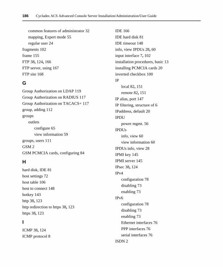
186 Cyclades ACS Advanced Console Server Installation/Administration/User Guide
common features of administrator 32mapping, Expert mode 55regular user 24
fragments 102frame 155FTP 38, 124, 166FTP server, using 167FTP site 168
GGroup Authorization on LDAP 119Group Authorization on RADIUS 117Group Authorization on TACACS+ 117group, adding 112groups
outletsconfigure 65view information 59
groups, users 111GSM 2GSM PCMCIA cards, configuring 84
Hhard disk, IDE 81host settings 72host table 106host to connect 148hotkey 143http 38, 123http redirection to https 38, 123https 38, 123
IICMP 38, 124ICMP protocol 8
IDE 166IDE hard disk 81IDE timeout 148info, view IPDUs 28, 60input interface 7, 102installation procedures, basic 13installing PCMCIA cards 20inverted checkbox 100IP
local 82, 151remote 82, 151
IP alias, port 147IP filtering, structure of 6IPaddress, default 20IPDU
power mgmt. 56IPDUs
info, view 60view information 60
IPDUs info, view 28IPMI key 145IPMI server 145IPsec 38, 124IPv4
configuration 78disabling 73enabling 73
IPv6configuration 78disabling 73enabling 73Ethernet interfaces 76PPP interfaces 76serial interfaces 76
ISDN 2
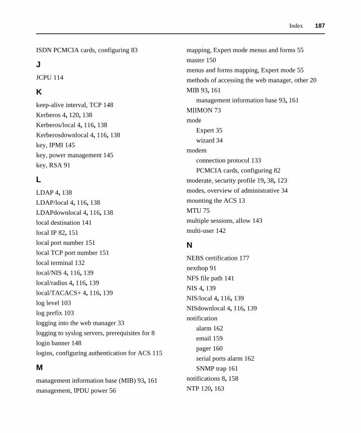
Index 187
ISDN PCMCIA cards, configuring 83
JJCPU 114
Kkeep-alive interval, TCP 148Kerberos 4, 120, 138Kerberos/local 4, 116, 138Kerberosdownlocal 4, 116, 138key, IPMI 145key, power management 145key, RSA 91
LLDAP 4, 138LDAP/local 4, 116, 138LDAPdownlocal 4, 116, 138local destination 141local IP 82, 151local port number 151local TCP port number 151local terminal 132local/NIS 4, 116, 139local/radius 4, 116, 139local/TACACS+ 4, 116, 139log level 103log prefix 103logging into the web manager 33logging to syslog servers, prerequisites for 8login banner 148logins, configuring authentication for ACS 115
Mmanagement information base (MIB) 93, 161management, IPDU power 56
mapping, Expert mode menus and forms 55master 150menus and forms mapping, Expert mode 55methods of accessing the web manager, other 20MIB 93, 161
management information base 93, 161MIIMON 73mode
Expert 35wizard 34
modemconnection protocol 133PCMCIA cards, configuring 82
moderate, security profile 19, 38, 123modes, overview of administrative 34mounting the ACS 13MTU 75multiple sessions, allow 143multi-user 142
NNEBS certification 177nexthop 91NFS file path 141NIS 4, 139NIS/local 4, 116, 139NISdownlocal 4, 116, 139notification
alarm 162email 159pager 160serial ports alarm 162SNMP trap 161
notifications 8, 158NTP 120, 163
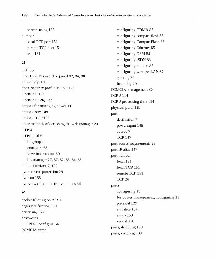
188 Cyclades ACS Advanced Console Server Installation/Administration/User Guide
server, using 163number
local TCP port 151remote TCP port 151trap 161
OOID 95One Time Password required 82, 84, 88online help 170open, security profile 19, 38, 123OpenSSH 127OpenSSL 126, 127options for managing power 11options, stty 148options, TCP 103other methods of accessing the web manager 20OTP 4OTP/Local 5outlet groups
configure 65view information 59
outlets manager 27, 57, 62, 63, 64, 65output interface 7, 102over current protection 29overrun 155overview of administrative modes 34
Ppacket filtering on ACS 6pager notification 160parity 44, 155passwords
IPDU, configure 64PCMCIA cards
configuring CDMA 88configuring compact flash 86configuring CompactFlash 86configuring Ethernet 85configuring GSM 84configuring ISDN 83configuring modem 82configuring wireless LAN 87ejecting 89installing 20
PCMCIA management 80PCPU 114PCPU processing time 114physical ports 129port
destination 7powermgmt 145source 7TCP 147
port access requirements 25port IP alias 147port number
local 151local TCP 151remote TCP 151TCP 26
portsconfiguring 19for power management, configuring 11physical 129statistics 154status 153virtual 150
ports, disabling 130ports, enabling 130

Index 189
power management 9, 133configuring 11configuring ports for 11connection protocol 133from ACS command line 12IPDU 56key 145through the web manager 12
power, options for managing 11powermgmt port 145ppp 82, 133ppp-no auth 133pre-installation requirements 13prerequisites for
logging to syslog servers 8using the web manager 3
pre-shared secret 91privilege users 143profiles
security 122serial port settings and security 39, 124
protocol 151authentication 91connection 26, 43ICMP 8modem connection 133power management connection 133terminal server (TS) profile connection 131UDP 7
Rraccess 117raccess authorization 117Radius 5, 139Radius/downlocal 116
Radius/local 5, 116, 139Radiusdownlocal 5, 139RAM 165raw socket 132raw, console 131reboot 169reboot the ACS 169record time stamp 141regular user 111regular user forms 24remote destination 141remote IP 82, 151remote TCP port number 151replacing the battery 179requirements, port access 25requirements, pre-installation 13root 2, 3, 16
access, allow SSH 38, 123access, SSH 55
routes, static 107RPC 38, 124RS232 signal 154RSA key 91rule, add 7run checksum 168RX bytes 155
Ssafety precautions 176secured, security profile 19, 38, 123security
profile custom 19profile default 19profile moderate 19, 38, 123profile open 19, 38, 123
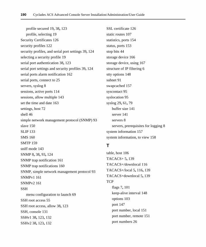
190 Cyclades ACS Advanced Console Server Installation/Administration/User Guide
profile secured 19, 38, 123profile, selecting 19
Security Certificates 126security profiles 122security profiles, and serial port settings 39, 124selecting a security profile 19serial port authentication 38, 123serial port settings and security profiles 39, 124serial ports alarm notification 162serial ports, connect to 25servers, syslog 8sessions, active ports 114sessions, allow multiple 143set the time and date 163settings, host 72shell 46simple network management protocol (SNMP) 93slave 150SLIP 133SMS 160SMTP 159sniff mode 143SNMP 8, 38, 93, 124SNMP trap notification 161SNMP trap notifications 160SNMP, simple network management protocol 93SNMPv1 161SNMPv2 161SSH
menu configuration to launch 69SSH root access 55SSH root access, allow 38, 123SSH, console 131SSHv1 38, 123, 132SSHv2 38, 123, 132
SSL certificate 126static routes 107statistics, ports 154status, ports 153stop bits 44storage device 166storage device, using 167structure of IP filtering 6stty options 148subnet 91swapcached 157syscontact 95syslocation 95syslog 29, 61, 79
buffer size 141server 141servers 8servers, prerequisites for logging 8
system information 157system information, to view 158
Ttable, host 106TACACS+ 5, 139TACACS+/downlocal 116TACACS+/local 5, 116, 139TACACS+downlocal 5, 139TCP
flags 7, 101keep-alive interval 148options 103port 147port number, local 151port number, remote 151port numbers 26
Index 191
sequence 103Technical support 182Telnet 38, 123, 132Telnet, bidirectional 132, 134Telnet, console 131TelnetSSH, console 131terminal profile menu 69terminal server (TS) profile connection protocols
131terminal type 148terminal, local 132TFTP 165time/date 162
daylight savings time 164timer, watchdog 165to configure ACS boot 165to reboot the ACS 169to set the time and date 163to upgrade the ACS’s firmware 169to view system information 158trap notification, SNMP 161trap number 161trigger, alarm 159TS profile connection protocols, terminal server 131TTY 114TX bytes 154
UUDP protocol 7updelay 73upgrade
ACS’s firmware 169firmware 168
upgrade firmwareCyclades PM IPDU 63
usage, CPU 114user
adding 112multi 142regular 111
user authorization 117user forms, regular 24users
adding 19administering 9configure power management 66privilege 143types of 3
users and groups 111users/groups, authorized 137using a storage device 167using an FTP server 167using an NTP server 163using the web manager, prerequisites for 3
Vview IPDUs info 28, 60view system information 158virtual ports 150vpn 5vpn connections 89
Wwatchdog timer 165web manager 2
logging into 33other methods of accessing 20power management 12prerequisites for using 3
windows EMS 148

192 Cyclades ACS Advanced Console Server Installation/Administration/User Guide
wireless LAN PCMCIA cards, configuring 87wiz command 15wizard mode 34
working inside the ACS console server 178
XX.509 Certificate on SSH 127

FCC Warning Statement
The Cyclades ACS advanced console server has been tested and found to comply with the limits for Class A digital devices, pursuant to Part 15 of the FCC rules. These limits are designed to provide reasonable protection against harmful interference when the equipment is operated in a commercial environment.
This equipment generates, uses and can radiate radio frequency energy and, if not installed and used in accordance with the Installation and Service Manual, may cause harmful interference to radio communications.
Operation of this equipment in a residential area is likely to cause harmful interference in which case the user is required to correct the problem at his or her own expense.
Notice about FCC Compliance for All Cyclades ACS Advanced Console Server Models
To comply with FCC standards, the Cyclades ACS advanced console server requires the use of a shielded CAT 5 cable for the Ethernet interface. Notice that this cable is not supplied with either of the products and must be provided by the customer.
Canadian DOC Notice
The Cyclades ACS advanced console server does not exceed the Class A limits for radio noise emissions from digital apparatus set out in the Radio Interference Regulations of the Canadian Department of Communications.
L’Cyclades ACS advanced console server n’émete pas de bruits radioélectriques dépassant les limites applicables aux appareils numériques de la classe A prescrites dans le règlement sur le brouillage radioélectrique edicté par le Ministère des Communications du Canada.
Safety and EMC Approvals and Markings
FCC Part 15 A, ICES-003, C-Tick, VCCI Class A, BSMI Class A, MIC Class A, CE (EN55022 Class A, EN55024, EN60950-1), GS, CB, CSA/UL 60950-1, Solaris Ready™, NEBS for ACS 16 NEBS and ACS 32 NEBS with single or dual DC power supplies

Installation/Administration/User Guide
For Technical Support:
www.avocent.com/support
590-660-501C
Cyclades® ACS