CWAP Quick Start Guide - RTSoft Functional Block Diagram Figure 1 contains an overview of the CWAP...
20
CWAP – Quick Start Guide Document Revision: Release 1.0
Transcript of CWAP Quick Start Guide - RTSoft Functional Block Diagram Figure 1 contains an overview of the CWAP...
CWAP – Quick Start Guide Document Revision: Release 1.0
i
» Table of Contents «
1 User Information ................................................................................ 1
1.1 About This Document ...................................................................................................................... 1
1.2 Copyright Notice .............................................................................................................................. 1
1.3 Trademark Notice ............................................................................................................................ 1
1.4 Standards ......................................................................................................................................... 1
1.5 Warranty........................................................................................................................................... 2
1.6 Referenced Documents ................................................................................................................... 2
1.7 Technical Support ............................................................................................................................ 2
1.8 Important Instructions ...................................................................................................................... 2
1.9 Exclusion of liability notice ............................................................................................................... 3
2 Safety instructions ............................................................................. 4
2.1 Electrostatic Discharge (ESD) ......................................................................................................... 4
2.2 Precautions for Installing the System .............................................................................................. 4
3 Introduction ....................................................................................... 5
3.1 Product Description .......................................................................................................................... 5
3.2 Functional Block Diagram ................................................................................................................ 5
3.3 Equipment Definition ........................................................................................................................ 6
3.4 Major Hardware Components .......................................................................................................... 6
3.5 CWAP Orderable Part Numbers ...................................................................................................... 6
4 Starting Up ........................................................................................ 7
4.1 CWAP Equipment ............................................................................................................................ 7
4.2 Power Up and Log In ....................................................................................................................... 8
4.3 Connecting using the Console Port ................................................................................................. 8
4.3.1 Reset CWAP to factory default settings............................................................................... 9
4.4 Web-based GUI ............................................................................................................................. 10
4.4.1 Connecting using the WAN Port ........................................................................................ 10
ii
4.4.2 Connecting using the LAN Port ......................................................................................... 10
4.5 GUI Login Screen .......................................................................................................................... 10
4.6 GUI Quick Setup Configuration ..................................................................................................... 11
4.6.1 System Configuration......................................................................................................... 11
4.7 Flag Antennas and Bracket Assembly Installation ........................................................................ 13
5 Support and Service ........................................................................ 14
5.1 Technical Support .......................................................................................................................... 14
5.2 Returning Defective Merchandise .................................................................................................. 14
6 Appendix A: List of Figures ............................................................. 15
7 Appendix B: List of Tables ............................................................... 16
8 Appendix C: Document Revision History ......................................... 17
1
1 User Information
1.1 About This Document
This document provides information about products from Kontron and/or its subsidiaries. No warranty of suitability,
purpose, or fitness is implied. While every attempt has been made to ensure that the information in this document is
accurate, the information contained within is supplied “as-is” and is subject to change without notice.
1.2 Copyright Notice
Copyright © 2012 Kontron. All rights reserved. No part of this document may be reproduced, transmitted, transcribed,
stored in a retrieval system, or translated into any language or computer language, in any form or by any means
(electronic, mechanical, photocopying, recording, or otherwise), without the express written permission of Kontron.
1.3 Trademark Notice
This document many include names, company logos and trademarks, which are registered trademarks and, therefore,
proprietary to their respective owners.
1.4 Standards
Standard Description
ARINC 763-3 Network Server System
D6-36440 Boeing Standard Cabin Systems Requirement Document FED-STD-595 Colors Used in
Federal Procurement
IEEE 802.11a Wireless LAN Media Access Control (MAC) and Physical Layer (PHY) Specifications –
High-speed Physical Layer in the 5 GHz Band.
IEEE 802.11b Physical and Media Access Control (MAC) layer definition for ISO 7 stack
communications devices.
IEEE 802.11g
IEEE Standard for Information Technology - Telecommunications and Information
Exchange Between Systems - Local and Metropolitan Area Networks - Specific
Requirements - Part 11: Wireless LAN Media Access Control (MAC) and Physical Layer
(PHY) Specifications: Further Higher Data Rate Extension in the 2.4 GHz Band.
IEEE 802.11n
IEEE Standard for Information Technology - Telecommunications and information
exchange between systems-Local and metropolitan area networks-Specific requirements-
Part 11: Wireless LAN Medium Access Control (MAC) and Physical Layer (PHY)
specifications. IEEE 802.1x Port-Based Network Access Control
IEEE 802.3
Information Exchange Between Systems—Local and Metropolitan Area Networks—
Specific Requirements—Part 3: Carrier Sense Multiple Access With Collision Detection
(CSMA/CD) Access Method and Physical Layer Specifications. RTCA/DO-254 Design
Assurance Guidance For Airborne Electronic Hardware
RTCA/DO-160F Environmental Conditions and Test Procedures For Airborne Equipment RTCA/DO-178B
Software Considerations in Airborne Systems and Equipment
FAR-25.853a Cert
Federal Aviation Regulations for Flammability ISO 9001/2008 International Organization
for Standardization, Quality Management ANSI/IPC-A-620 Acceptability of Electronic
Assemblies ANSI/J-STD-002 Solderability Tests for Component Leads MIL-C-5542
Chemical Conversion Coatings on Aluminum and Aluminum Alloys
2
1.5 Warranty
This Kontron product is warranted against defects in material and workmanship for the warranty period from the date
of shipment. During the warranty period, Kontron will at its discretion decide to repair or replace defective products.
Within the warranty period, the repair of products is free of charge as long as warranty conditions are observed.
The warranty does not apply to defects resulting from improper or inadequate maintenance or handling by the buyer,
unauthorized modification or misuse, operation outside of the product’s environmental specifications or improper
installation or maintenance.
Kontron will not be responsible for any defects or damages to other products not supplied by Kontron that are caused
by a faulty Kontron product.
1.6 Referenced Documents
Kontron Document # 73001000-FAT, Factory Acceptance Test Procedure, CWAP
Kontron Document # 73001000-CMM Component Maintenance Manual (CMM), CWAP
Kontron Document # 73001000-ESS Environmental Stress Screen Procedure, CWAP
Kontron Document # 730010000-FMEA, Rev A, CWAP
Motorola AP-7131 Series Access Point Product Reference Guide
1.7 Technical Support
Technicians and engineers from Kontron and/or its subsidiaries are available for technical support. We are committed
to making our product easy to use and will help you use our products in your systems.
Please consult our Web site at http://www.kontron.com/support for the latest product documentation, utilities, drivers
and support contacts.
1.8 Important Instructions
The following general instructions should always be followed in order to assure the proper operation of the COBALT
unit, the safety of operators and the preservation of warranty coverage.
Warning!
All precautions, procedures, and safeguards to prevent damage due to ESD, and promote the safe handling of electronic components must be followed.
It is assumed that a competent technician familiar with electro-mechanical assemblies will be performing any testing
or troubleshooting of the unit. For detailed interconnection of power and signal wiring refer to the sections on
Physical I/O and Starting Up.
3
IMPORTANT: Avoid removing any identification plates, serial numbers or warning labels unless specifically
authorized by the manufacturer.
1.9 Exclusion of liability notice
Exemption from Liability for Accidents
Should the user disregard the instructions (specifically the safety instructions) in this manual and possibly on the
device, Kontron will be exempt from legal liability for accidents.
Limitation of Liability / Warranty Obligations
In the event of damage to the device, which is caused by a failure to observe the instructions (specifically the safety
instructions) in this manual and possibly on the device, Kontron will not be required to honor the warranty, including
during the warranty period, and will be exempt from legal liability for accidents.
4
2 Safety instructions
2.1 Electrostatic Discharge (ESD)
Electronic boards and their components are sensitive to static electricity. Therefore, care must be taken
during all handling operations and inspections of this product, in order to ensure product integrity at all
times. Do not handle this product out of its protective enclosure while it is not used for operational
purposes unless it is otherwise protected.
A sudden electrostatic discharge can destroy sensitive components. Proper packaging and grounding
rules must be observed. Always take the following precautions.
1. Transport boards and cards in electrostatically secure containers or bags.
2. Keep electrostatically sensitive components in their containers, until they arrive at an electrostatically
protected workplace.
3. Only touch electrostatically sensitive components when you are properly earthed.
4. Store electrostatically sensitive components in protective packaging or on anti-static mats.
2.2 Precautions for Installing the System
Important Instructions!
Please follow the corresponding instructions in this manual when installing/mounting the CWAP platform.
Please observe all specified dimensions required for mounting included in the drawing with outline
dimensions
When installing the CWAP, there must be at least 40 mm (approximately 1.575") free space around the
cooling fins to prevent the system overheating.
Leave approximately 4.0” (100 mm) of free space to the front and rear of the unit in order to have access
to the connector interfaces to properly connect the peripherals.
The cooling fins of the chassis must not be obstructed.
The platform must be firmly attached to a clean flat and solid mounting surface. Use proper fastening
materials suitable for the mounting surface. Ensure that the mounting surface type and the used mounting
solution safely support the load of the cobalt and the attached components.
Follow the local/national regulations for grounding. A ground bonding measurement (between CWAP
chassis ground and the mounting surface) should be conducted to ensure proper safety and EMI
characteristics are maintained.
The voltage feeds must not be overloaded. Adjust the cabling and the external overcharge protection to
correspond with the electrical data indicated on the type label.
5
3 Introduction
3.1 Product Description
The Cabin Wireless Access Point (CWAP) is a network distribution system designed specifically for
commercial airborne applications. The CWAP complies with IEEE 802.11a/b/g/n wireless standards
utilizing a Commercial-Off-The-Shelf (COTS) wireless access point in the appropriately assigned radio
frequency spectrum to facilitate wireless communications to other personal and aircraft devices. The
CWAP provides a bridge between IEEE 802.3 wired Ethernet LANs and IEEE 802.11a/b/g/n compliant
wireless networks.
The CWAP is provided with aircraft level discrete inputs and outputs to facilitate event notification and
equipment status to and from other aircraft systems, including remote control ON/OFF. The product is
equipped with an avionics wide frequency (360-800Hz) power supply unit with a 200msec holdup
capability for power interruptions. The CWAP requires no active cooling system, and has capabilities for
built-in diagnostics reporting. The CWAP is designed to comply with the general requirements identified
in Section 8 (Cabin Wireless LAN Unit) of the ARINC 763-3 Specification. The unit communicates to a
host server by physical connection over wired 10/100/1000Base-T interfaces.
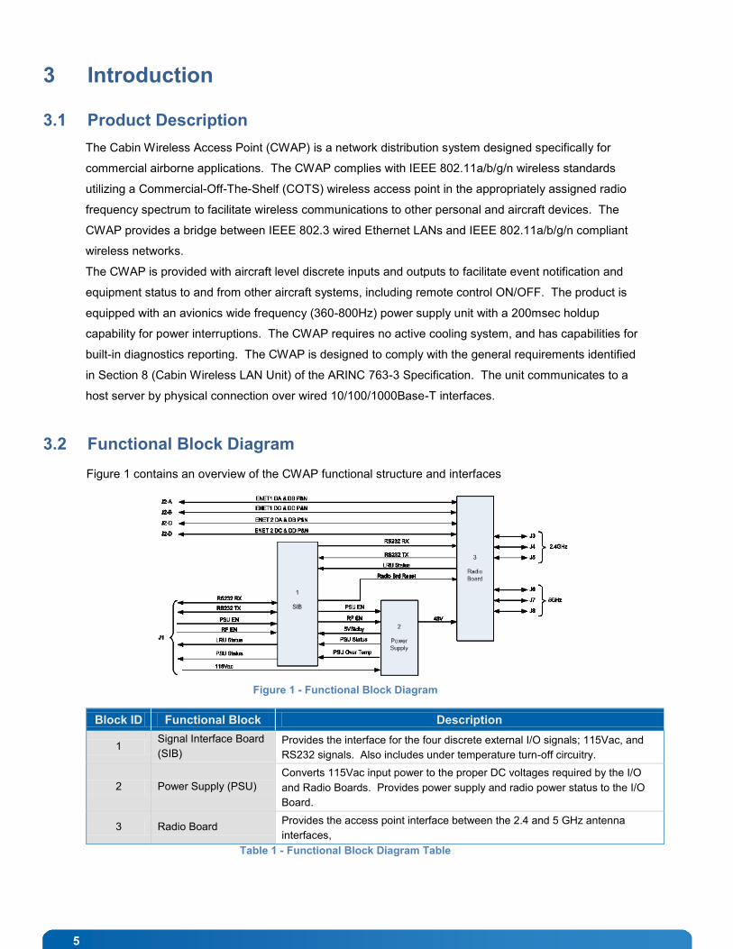
3.2 Functional Block Diagram
Figure 1 contains an overview of the CWAP functional structure and interfaces
Figure 1 - Functional Block Diagram
Block ID Functional Block Description
1 Signal Interface Board
(SIB)
Provides the interface for the four discrete external I/O signals; 115Vac, and
RS232 signals. Also includes under temperature turn-off circuitry.
2 Power Supply (PSU)
Converts 115Vac input power to the proper DC voltages required by the I/O
and Radio Boards. Provides power supply and radio power status to the I/O
Board.
3 Radio Board Provides the access point interface between the 2.4 and 5 GHz antenna
interfaces,
Table 1 - Functional Block Diagram Table
6
3.3 Equipment Definition
The CWAP leverages state-of-the-art COTS hardware to establish a rugged, versatile, high performance
wireless network access product. The minimal overall size and weight facilitates a variety of installation
options. Figure 1 depicts the general block diagram of the unit.
The standard features of the CWAP include:
COTS architecture based on 802.11a/b/g/n standards for wireless communications
Discrete inputs to control remote On/Off and RF Enable/Disable
Discrete Outputs for RF Status and Power Supply Status
Internal (AC/DC) power with interruption holdup capability
Dual Ethernet 10/100/1000BaseT ports interface to Airborne Network Server Unit and/or
additional CWAP
Lightweight and compact electro-mechanical packaging
Mil Circular connector for signal/power interfaces
Mil Circular connector with Quadrax inserts for Ethernet interfaces
Six (6) RF SMA-RP coaxial connectors for remote antenna attachment
3.4 Major Hardware Components
The CWAP major hardware assemblies are:
COTS Wireless Access Point Assembly
Power Supply Unit (PSU) with build-in hold-up (200msec)
Signal Interface Board (SIB) circuit card assembly for aircraft discrete input/output
Status Indicators, LEDs
External connection points for power and I/O, Ethernet, and external antenna
3.5 CWAP Orderable Part Numbers
Model Number Description
73001000-001 LRU, CWAP ASSY, (INTL VERSION)
73001000-002 LRU, CWAP ASSY, (US VERSION)
73001001-001 LRU, KIT, FLAG ANTENNAS, CWAP
5007120-1 KIT, EXTERNAL CWAP CABLES
Table 2 - CWAP Orderable Part Numbers
7
4 Starting Up
The CWAP system is ready to use out-of-the-box. Evaluation units come with a complete interface cable
set as shown in the following table. For production units, cable harness assemblies can be ordered
separately. If you are building your own cable harness, see Section 5 for signal pin out and mating
connector information.
The CWAP is a conduction cooled system and requires no additional fan assist if operated in the defined
environmental conditions. Note that the unit may get warm and/or hot to the touch and should be handled
with caution during use.
Note, there is a temperature sensor that prevents the CWAP from turning on below -20ºC (+/-2ºC).
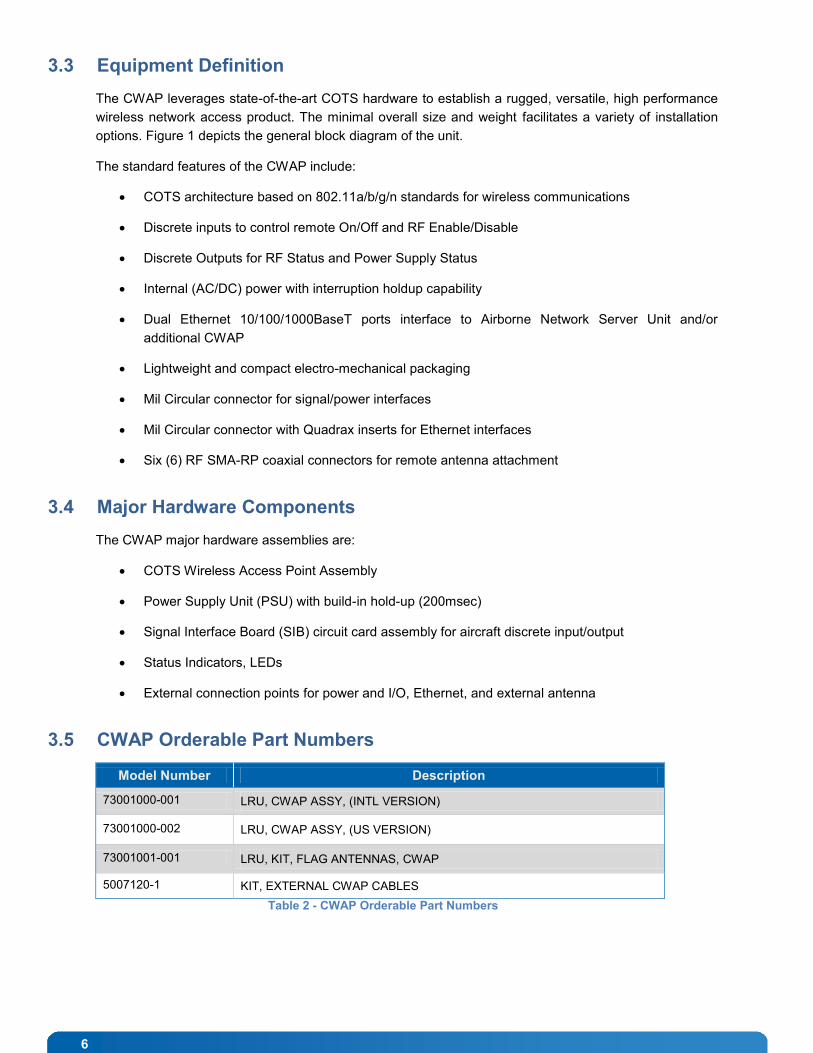
4.1 CWAP Equipment
Label Description Equipment
1
Cable Assembly with 2x
GbE RJ45 connectors
PN: 5006862-1
2 CWAP
PN: 73001000-00x
3
Cable Assembly with AC
3-prong power plug and
DB-9 console connector.
PN: 5006863-1
4
Flag Antennas (6), bracket
not shown.
PN: 73001001-001
Table 3 - CWAP Equipment
8
4.2 Power Up and Log In
At a minimum, the P1 power/signal cable assembly (Reference Label 3 in the above table) is required to
be connected to the CWAP system, part number 5006863-1. Note, the 5006863-1 cable assembly has
the two discrete inputs bypassed (loop-back) in order for the CWAP to turn on when AC power is applied.
Warning!
The specified voltage input range is from 97 to 134 VAC, 47 - 800 Hz, single-phase power.
DO NOT connect to 220 VAC
The power source must supply a minimum of 25 W.
The power source must be switched off via a 2-pole disconnect device and must be easily accessible.
Ambient temperature must be above -20ºC for the CWAP to turn on.
Power is not switched internally and the unit will boot up as soon as power is applied.
Properly install the P1 (MIL J1) circular cable assembly connector to the mating connector on the CWAP
Location J1. The AC power source must be switched off via a 2-pole disconnect device to make sure that
no voltage is present at the terminal during the connecting procedure. Connect the other end of the AC
power cord to the power source (not provided). Switch on the AC power source via the disconnect device.
To log into the system use the following:
User: admin
Password: motorola
If you reset the CWAP to factory defaults, the password will be “motorola”.
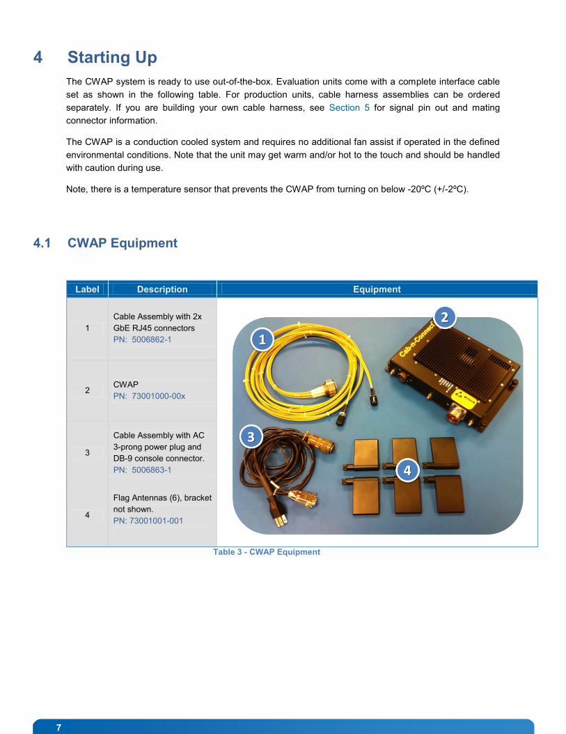
4.3 Connecting using the Console Port
Ensure that the P2 connector (DB9) of 5006863-1 cable assembly is installed correctly and secured to the
serial port on a PC. Open a terminal application and set the console port settings as follows:
Figure 2 - Console Port Setting
9
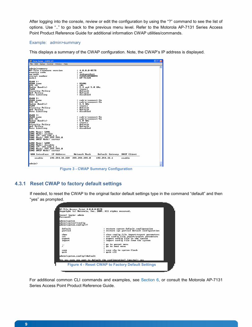
After logging into the console, review or edit the configuration by using the “?” command to see the list of
options. Use “..” to go back to the previous menu level. Refer to the Motorola AP-7131 Series Access
Point Product Reference Guide for additional information CWAP utilities/commands.
Example: admin>summary
This displays a summary of the CWAP configuration. Note, the CWAP’s IP address is displayed.
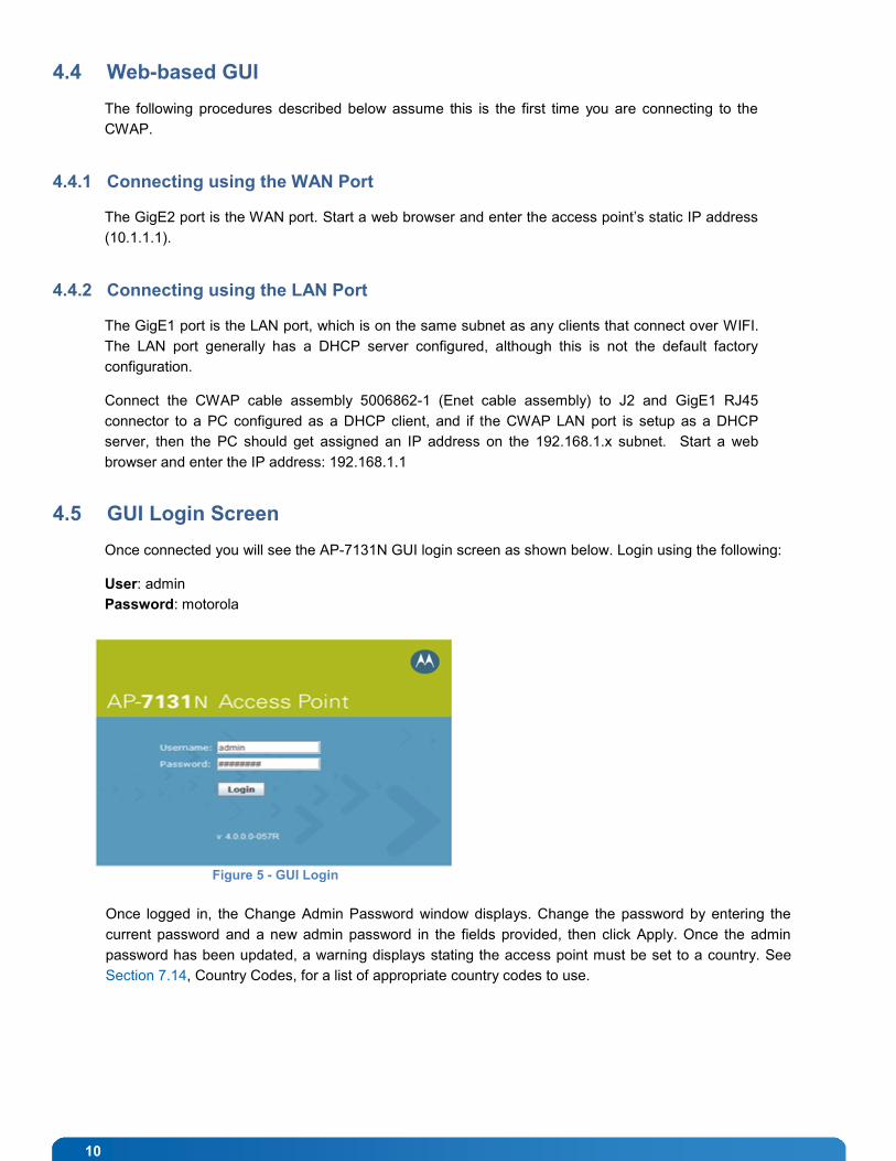
4.3.1 Reset CWAP to factory default settings
If needed, to reset the CWAP to the original factor default settings type in the command “default” and then
“yes” as prompted.
For additional common CLI commands and examples, see Section 6, or consult the Motorola AP-7131
Series Access Point Product Reference Guide.
Figure 3 - CWAP Summary Configuration
Figure 4 - Reset CWAP to Factory Default Settings
10
4.4 Web-based GUI
The following procedures described below assume this is the first time you are connecting to the
CWAP.
4.4.1 Connecting using the WAN Port
The GigE2 port is the WAN port. Start a web browser and enter the access point’s static IP address
(10.1.1.1).
4.4.2 Connecting using the LAN Port
The GigE1 port is the LAN port, which is on the same subnet as any clients that connect over WIFI.
The LAN port generally has a DHCP server configured, although this is not the default factory
configuration.
Connect the CWAP cable assembly 5006862-1 (Enet cable assembly) to J2 and GigE1 RJ45
connector to a PC configured as a DHCP client, and if the CWAP LAN port is setup as a DHCP
server, then the PC should get assigned an IP address on the 192.168.1.x subnet. Start a web
browser and enter the IP address: 192.168.1.1
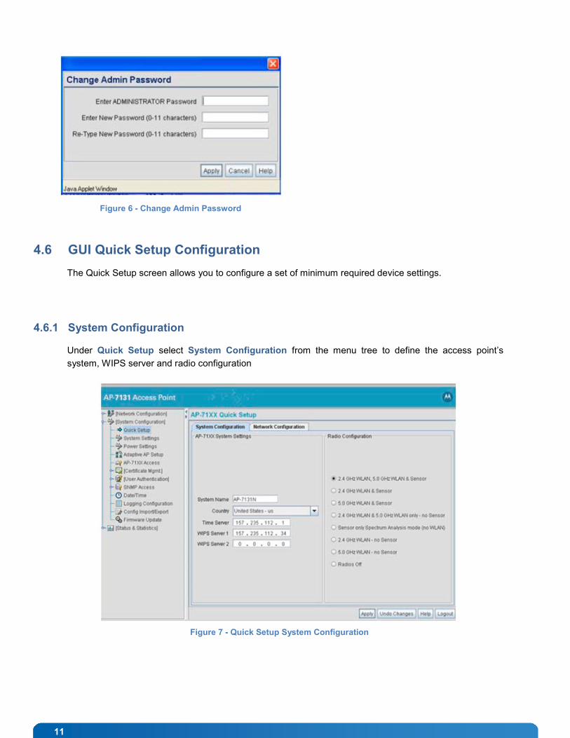
4.5 GUI Login Screen
Once connected you will see the AP-7131N GUI login screen as shown below. Login using the following:
User: admin
Password: motorola
Once logged in, the Change Admin Password window displays. Change the password by entering the
current password and a new admin password in the fields provided, then click Apply. Once the admin
password has been updated, a warning displays stating the access point must be set to a country. See
Section 7.14, Country Codes, for a list of appropriate country codes to use.
Figure 5 - GUI Login
11
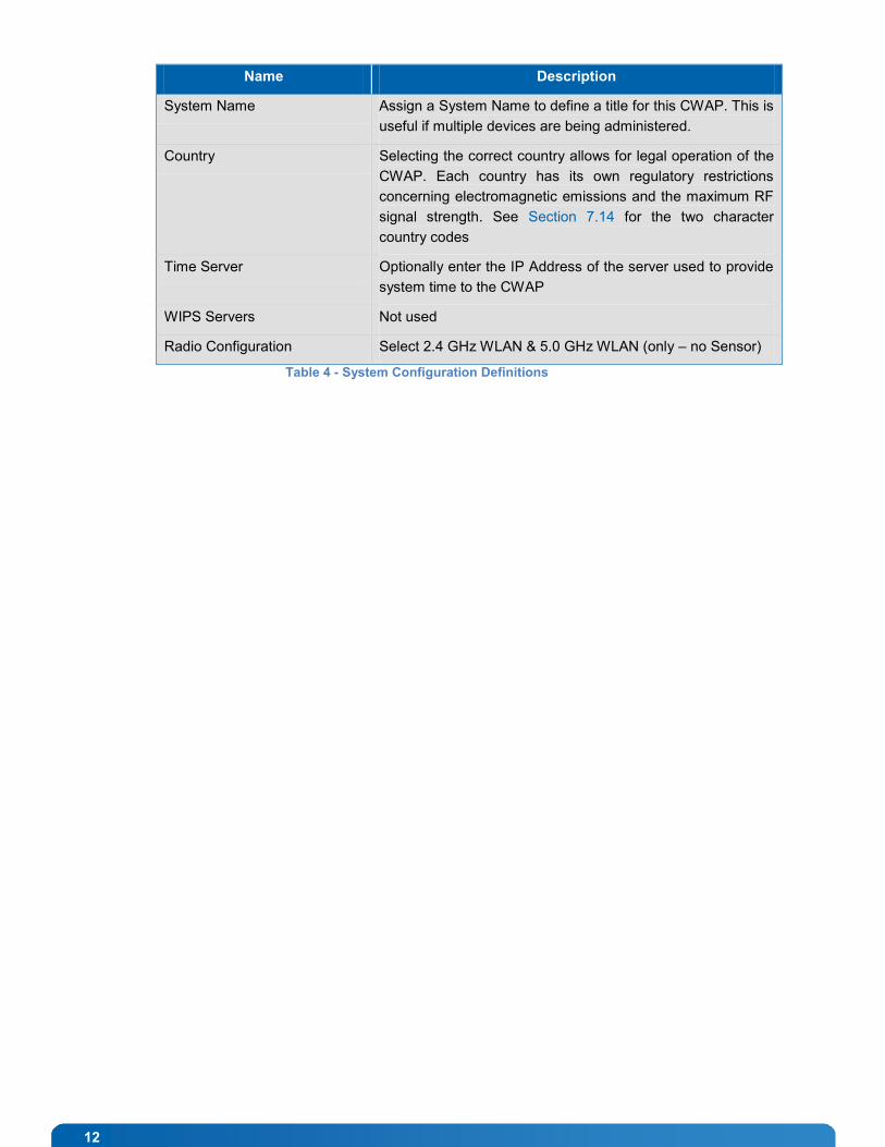
4.6 GUI Quick Setup Configuration
The Quick Setup screen allows you to configure a set of minimum required device settings.
4.6.1 System Configuration
Under Quick Setup select System Configuration from the menu tree to define the access point’s
system, WIPS server and radio configuration
Figure 6 - Change Admin Password
Figure 7 - Quick Setup System Configuration
12
Name Description
System Name Assign a System Name to define a title for this CWAP. This is
useful if multiple devices are being administered.
Country Selecting the correct country allows for legal operation of the
CWAP. Each country has its own regulatory restrictions
concerning electromagnetic emissions and the maximum RF
signal strength. See Section 7.14 for the two character
country codes
Time Server Optionally enter the IP Address of the server used to provide
system time to the CWAP
WIPS Servers Not used
Radio Configuration Select 2.4 GHz WLAN & 5.0 GHz WLAN (only – no Sensor)
Table 4 - System Configuration Definitions
13
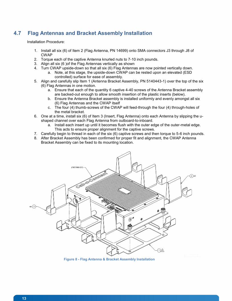
4.7 Flag Antennas and Bracket Assembly Installation
Installation Procedure:
1. Install all six (6) of Item 2 (Flag Antenna, PN 14699) onto SMA connectors J3 through J8 of CWAP
2. Torque each of the captive Antenna knurled nuts to 7-10 inch pounds. 3. Align all six (6 )of the Flag Antennas vertically as shown 4. Turn CWAP upside-down so that all six (6) Flag Antennas are now pointed vertically down.
a. Note, at this stage, the upside-down CWAP can be rested upon an elevated (ESD controlled) surface for ease of assembly.
5. Align and carefully slip Item 1 (Antenna Bracket Assembly, PN 5140443-1) over the top of the six (6) Flag Antennas in one motion.
a. Ensure that each of the quantity 6 captive 4-40 screws of the Antenna Bracket assembly are backed-out enough to allow smooth insertion of the plastic inserts (below).
b. Ensure the Antenna Bracket assembly is installed uniformly and evenly amongst all six (6) Flag Antennas and the CWAP itself
c. The four (4) thumb-screws of the CWAP will feed-through the four (4) through-holes of the metal bracket.
6. One at a time, install six (6) of Item 3 (Insert, Flag Antenna) onto each Antenna by slipping the u-shaped channel over each Flag Antenna from outboard-to-inboard.
a. Install each insert up until it becomes flush with the outer edge of the outer-metal edge. This acts to ensure proper alignment for the captive screws.
7. Carefully begin to thread in each of the six (6) captive screws and then torque to 5-6 inch pounds. 8. After Bracket Assembly has been confirmed for proper fit and alignment, the CWAP Antenna
Bracket Assembly can be fixed to its mounting location.
Figure 8 - Flag Antenna & Bracket Assembly Installation
14
5 Support and Service
5.1 Technical Support
Technicians and engineers from Kontron Embedded Modules GmbH and/or its subsidiaries are available
for technical support. We are committed to making our product easy to use and will help you use our
products in your systems.
Please consult our Web site at http://www.kontron.com/support for the latest product documentation,
utilities, drivers.
5.2 Returning Defective Merchandise
Please use the website to obtain latest information on returning merchandise.
http://us.kontron.com/support/rma-information/
All equipment returned to Kontron must have a Return Material Authorization (RMA) number assigned
exclusively by Kontron. Kontron cannot be held responsible for any loss or damage caused to the
equipment received without an RMA number. The Buyer accepts responsibility for all freight charges for
the return of goods to Kontron's designated facility. Kontron will pay return freight charges back to the
Buyer's location in the event that the equipment is repaired or replaced within the warranty period
stipulated herewith.
To request a Return Material Authorization (RMA) number
Be prepared to supply the unit serial number, reason for return and original ship date
Place call to 800-480-0044 to receive RMA number (toll free in the US and Canada) "OR"
E-mail the information to [email protected] to receive RMA number
RMA Request Form (found on website)
Return defective material (unless instructed otherwise with issuance of RMA) to:
Contact and Delivery Address
Kontron America 14118 Stowe Dr Poway, CA 92064 Attn: RMA number
15
6 Appendix A: List of Figures
Figure 1 - Functional Block Diagram ................................................................ 5
Figure 2 - Console Port Setting .................................................................... 8
Figure 3 - CWAP Summary Configuration ............................................................ 9
Figure 4 - Reset CWAP to Factory Default Settings ..................................................... 9
Figure 5 - GUI Login ........................................................................... 10
Figure 6 - Change Admin Password ............................................................... 11
Figure 7 - Quick Setup System Configuration ......................................................... 11
Figure 14 - Flag Antenna & Bracket Assembly Installation ................................................ 13
16
7 Appendix B: List of Tables
Table 1 - Functional Block Diagram Table ............................................................ 5
Table 2 - CWAP Orderable Part Numbers ............................................................ 6
Table 3 - CWAP Equipment ...................................................................... 7
Table 4 - System Configuration Definitions ........................................................... 12
17
8 Appendix C: Document Revision History
Revision Date By Changes
1.0 8/4/12 RJM Initial Release