CVT C TRANSMISSION/TRANSAXLE CVT...
208
CVT-1 CVT C TRANSMISSION/TRANSAXLE CONTENTS D E F G H I J K L M SECTION CVT A B CVT Revision; 2004 April 2003 Murano CVT INDEX FOR DTC ....................................................... 6 Alphabetical Index ................................................... 6 DTC No. Index ........................................................ 7 PRECAUTIONS ......................................................... 8 Precautions for Supplemental Restraint System (SRS) “AIR BAG” and “SEAT BELT PRE-TEN- SIONER” ................................................................. 8 Precautions for TCM and CVT Assembly Replace- ment ........................................................................ 8 EEPROM ERASING PATTERNS ......................... 8 METHOD FOR ERASING THE EEPROM IN THE TCM ..................................................................... 8 METHOD FOR WRITING DATA FROM THE ROM ASSEMBLY IN THE TRANSMISSION ....... 9 CHECK METHOD ................................................ 9 Removal and Installation Procedure for CVT Unit Connector ................................................................ 9 REMOVAL ............................................................ 9 INSTALLATION .................................................... 9 Precautions ........................................................... 10 Service Notice or Precautions ................................ 11 OBD-II SELF-DIAGNOSIS .................................. 11 Wiring Diagrams and Trouble Diagnosis ................ 11 PREPARATION ........................................................ 12 Special Service Tools ............................................ 12 Commercial Service Tools ..................................... 13 CVT FLUID .............................................................. 14 Checking CVT Fluid .............................................. 14 FLUID LEVEL CHECK ....................................... 14 FLUID CONDITION CHECK .............................. 15 Changing CVT Fluid .............................................. 15 CVT SYSTEM .......................................................... 16 Cross-Sectional View - RE0F09A ......................... 16 Control System ...................................................... 17 Hydraulic Control System ...................................... 18 TCM Function ........................................................ 19 CONTROL SYSTEM OUTLINE ......................... 19 CONTROL SYSTEM DIAGRAM ........................ 19 CAN Communication Unit For 2WD Models ......... 20 SYSTEM DESCRIPTION ................................... 20 TYPE 1/TYPE 2/TYPE 3/TYPE 4/TYPE 5/TYPE 6/TYPE 7/TYPE 8 ............................................... 20 TYPE 9/TYPE10/TYPE 11/TYPE 12/TYPE 13/ TYPE 14/TYPE 15/TYPE 16 .............................. 25 CAN Communication Unit For AWD Models ......... 30 SYSTEM DESCRIPTION ................................... 30 TYPE 17/TYPE 18/TYPE 19/TYPE 20/TYPE 21/ TYPE 22/TYPE 23/TYPE 24 .............................. 30 TYPE 25/TYPE26/TYPE 27/TYPE 28/TYPE 29/ TYPE 30/TYPE 31/TYPE 32 .............................. 35 Input/Output Signal of TCM ................................... 40 Line Pressure and Secondary Pressure Control ... 40 NORMAL CONTROL ......................................... 41 FEEDBACK CONTROL ..................................... 41 Shift Control ........................................................... 41 “D” POSITION .................................................... 41 “S”POSITION ..................................................... 41 “L” POSITION ..................................................... 42 DOWNHILL ENGINE BRAKE CONTROL (AUTO ENGINE BRAKE CONTROL) ............................. 42 KICKDOWN CONTROL ..................................... 42 Lock-Up and Select Control ................................... 42 TORQUE CONVERTER CLUTCH AND SELECT CONTROL VALVE CONTROL ........................... 43 Control Valve ......................................................... 44 FUNCTION OF CONTROL VALVE .................... 44 ON BOARD DIAGNOSTIC (OBD) SYSTEM ........... 45 Introduction ............................................................ 45 OBD-II Function for CVT System .......................... 45 One or Two Trip Detection Logic of OBD-II ........... 45 ONE TRIP DETECTION LOGIC ........................ 45 TWO TRIP DETECTION LOGIC ........................ 45 OBD-II Diagnostic Trouble Code (DTC) ................ 45 HOW TO READ DTC AND 1ST TRIP DTC ........ 45 HOW TO ERASE DTC ....................................... 46 HOW TO ERASE DTC (WITH CONSULT-II) ...... 47 HOW TO ERASE DTC (WITH GST) .................. 47 Malfunction Indicator Lamp (MIL) .......................... 48 DESCRIPTION ................................................... 48 TROUBLE DIAGNOSIS ........................................... 49
Transcript of CVT C TRANSMISSION/TRANSAXLE CVT...
CVT-1
CVT
C TRANSMISSION/TRANSAXLE
CONTENTS
D
E
F
G
H
I
J
K
L
M
SECTION CVTA
B
CVT
Revision; 2004 April 2003 Murano
CVT
INDEX FOR DTC ........................................................ 6Alphabetical Index .................................................... 6DTC No. Index ......................................................... 7
PRECAUTIONS .......................................................... 8Precautions for Supplemental Restraint System (SRS) “AIR BAG” and “SEAT BELT PRE-TEN-SIONER” .................................................................. 8Precautions for TCM and CVT Assembly Replace-ment ......................................................................... 8
EEPROM ERASING PATTERNS .......................... 8METHOD FOR ERASING THE EEPROM IN THE TCM ...................................................................... 8METHOD FOR WRITING DATA FROM THE ROM ASSEMBLY IN THE TRANSMISSION ........ 9CHECK METHOD ................................................. 9
Removal and Installation Procedure for CVT Unit Connector ................................................................. 9
REMOVAL ............................................................. 9INSTALLATION ..................................................... 9
Precautions ............................................................ 10Service Notice or Precautions .................................11
OBD-II SELF-DIAGNOSIS ...................................11Wiring Diagrams and Trouble Diagnosis .................11
PREPARATION ......................................................... 12Special Service Tools ............................................. 12Commercial Service Tools ...................................... 13
CVT FLUID ............................................................... 14Checking CVT Fluid ............................................... 14
FLUID LEVEL CHECK ........................................ 14FLUID CONDITION CHECK ............................... 15
Changing CVT Fluid ............................................... 15CVT SYSTEM ........................................................... 16
Cross-Sectional View - RE0F09A .......................... 16Control System ....................................................... 17Hydraulic Control System ....................................... 18TCM Function ......................................................... 19
CONTROL SYSTEM OUTLINE .......................... 19CONTROL SYSTEM DIAGRAM ......................... 19
CAN Communication Unit For 2WD Models .......... 20SYSTEM DESCRIPTION .................................... 20
TYPE 1/TYPE 2/TYPE 3/TYPE 4/TYPE 5/TYPE 6/TYPE 7/TYPE 8 ................................................ 20TYPE 9/TYPE10/TYPE 11/TYPE 12/TYPE 13/TYPE 14/TYPE 15/TYPE 16 ............................... 25
CAN Communication Unit For AWD Models .......... 30SYSTEM DESCRIPTION .................................... 30TYPE 17/TYPE 18/TYPE 19/TYPE 20/TYPE 21/TYPE 22/TYPE 23/TYPE 24 ............................... 30TYPE 25/TYPE26/TYPE 27/TYPE 28/TYPE 29/TYPE 30/TYPE 31/TYPE 32 ............................... 35
Input/Output Signal of TCM .................................... 40Line Pressure and Secondary Pressure Control .... 40
NORMAL CONTROL .......................................... 41FEEDBACK CONTROL ...................................... 41
Shift Control ............................................................ 41“D” POSITION ..................................................... 41“S”POSITION ...................................................... 41“L” POSITION ...................................................... 42DOWNHILL ENGINE BRAKE CONTROL (AUTO ENGINE BRAKE CONTROL) .............................. 42KICKDOWN CONTROL ...................................... 42
Lock-Up and Select Control .................................... 42TORQUE CONVERTER CLUTCH AND SELECT CONTROL VALVE CONTROL ............................ 43
Control Valve .......................................................... 44FUNCTION OF CONTROL VALVE ..................... 44
ON BOARD DIAGNOSTIC (OBD) SYSTEM ............ 45Introduction ............................................................. 45OBD-II Function for CVT System ........................... 45One or Two Trip Detection Logic of OBD-II ............ 45
ONE TRIP DETECTION LOGIC ......................... 45TWO TRIP DETECTION LOGIC ......................... 45
OBD-II Diagnostic Trouble Code (DTC) ................. 45HOW TO READ DTC AND 1ST TRIP DTC ......... 45HOW TO ERASE DTC ........................................ 46HOW TO ERASE DTC (WITH CONSULT-II) ....... 47HOW TO ERASE DTC (WITH GST) ................... 47
Malfunction Indicator Lamp (MIL) ........................... 48DESCRIPTION .................................................... 48
TROUBLE DIAGNOSIS ............................................ 49
CVT-2Revision; 2004 April 2003 Murano
DTC Inspection Priority Chart ................................. 49Fail-Safe ................................................................. 49
FAIL-SAFE FUNCTION ....................................... 49How To Perform Trouble Diagnosis For Quick and Accurate Repair ...................................................... 50
INTRODUCTION ................................................. 50WORK FLOW ...................................................... 51DIAGNOSTIC WORKSHEET .............................. 52
CVT Electrical Parts Location ................................. 54Circuit Diagram ....................................................... 55Inspections Before Trouble Diagnosis .................... 56
CVT FLUID CHECK ............................................ 56STALL TEST ........................................................ 56LINE PRESSURE TEST ...................................... 57ROAD TEST ........................................................ 59
Vehicle Speed When Shifting Gears ...................... 62TCM Input/Output Signal Reference Values ........... 63
TCM TERMINAL CONNECTOR LAYOUT .......... 63TCM INSPECTION TABLE .................................. 63
CONSULT-II ............................................................ 66FUNCTION .......................................................... 66WORK SUPPORT MODE WITH CONSULT-II .... 66SELF-DIAGNOSTIC PROCEDURE (WITH CONSULT-II) ....................................................... 70
Diagnostic Procedure Without CONSULT-II ........... 75OBD-II SELF-DIAGNOSTIC PROCEDURE (WITH GST) ......................................................... 75
DTC U1000 CAN COMMUNICATION LINE .............. 76Description .............................................................. 76On Board Diagnosis Logic ...................................... 76Possible Cause ....................................................... 76DTC Confirmation Procedure ................................. 76
WITH CONSULT-II .............................................. 76WITH GST ........................................................... 76
Wiring Diagram — CVT — CAN ............................. 77Diagnostic Procedure ............................................. 78
DTC P0615 START SIGNAL CIRCUIT ..................... 79Description .............................................................. 79On Board Diagnosis Logic ...................................... 79Possible Cause ....................................................... 79DTC Confirmation Procedure ................................. 79
WITH CONSULT-II .............................................. 79Wiring Diagram — CVT — STSIG .......................... 80Diagnostic Procedure ............................................. 81
DTC P0703 STOP LAMP SWITCH CIRCUIT ........... 83Description .............................................................. 83On Board Diagnosis Logic ...................................... 83Possible Cause ....................................................... 83DTC Confirmation Procedure ................................. 83
WITH CONSULT-II .............................................. 83Diagnostic Procedure ............................................. 83
DTC P0705 PARK/NEUTRAL POSITION SWITCH ... 85Description .............................................................. 85On Board Diagnosis Logic ...................................... 85Possible Cause ....................................................... 85DTC Confirmation Procedure ................................. 85
WITH CONSULT-II .............................................. 85WITH GST ........................................................... 85
Wiring Diagram — CVT — PNP/SW ...................... 86
Diagnostic Procedure ..............................................87Component Inspection ............................................89
PNP SWITCH ......................................................89DTC P0710 CVT FLUID TEMPERATURE SENSOR CIRCUIT ....................................................................90
Description ..............................................................90CONSULT-II Reference Value .................................90On Board Diagnosis Logic ......................................90Possible Cause .......................................................90DTC Confirmation Procedure ..................................90
WITH CONSULT-II ...............................................90WITH GST ...........................................................90
Wiring Diagram - CVT - FTS ...................................91Diagnostic Procedure ..............................................92Component Inspection ............................................94
CVT FLUID TEMPERATURE SENSOR ..............94DTC P0715 INPUT SPEED SENSOR CIRCUIT (PRI SPEED SENSOR) .....................................................95
Description ..............................................................95CONSULT-II Reference Value .................................95On Board Diagnosis Logic ......................................95Possible Cause .......................................................95DTC Confirmation Procedure ..................................95
WITH CONSULT-II ...............................................95WITH GST ...........................................................96
Wiring Diagram - CVT - PRSCVT ...........................97Diagnostic Procedure ..............................................98
DTC P0720 VEHICLE SPEED SENSOR CVT (SEC-ONDARY SPEED SENSOR) ...................................101
Description ............................................................101CONSULT-II Reference Value ...............................101On Board Diagnosis Logic ....................................101Possible Cause .....................................................101DTC Confirmation Procedure ................................101
WITH CONSULT-II .............................................101WITH GST .........................................................102
Wiring Diagram - CVT - SESCVT .........................103Diagnostic Procedure ............................................104
DTC P0725 ENGINE SPEED SIGNAL ....................108Description ............................................................108On Board Diagnosis Logic ....................................108Possible Cause .....................................................108DTC Confirmation Procedure ................................108
WITH CONSULT-II .............................................108Diagnostic Procedure ............................................108
DTC P0730 BELT DAMAGE ...................................110Description ............................................................ 110CONSULT-II Reference Value ............................... 110On Board Diagnosis Logic .................................... 110Possible Cause ..................................................... 110DTC Confirmation Procedure ................................ 110
WITH CONSULT-II ............................................. 110Diagnostic Procedure ............................................ 111
DTC P0740 TORQUE CONVERTER CLUTCH SOLENOID VALVE ..................................................112
Description ............................................................ 112CONSULT-II Reference Value ............................... 112On Board Diagnosis Logic .................................... 112Possible Cause ..................................................... 112
CVT-3
D
E
F
G
H
I
J
K
L
M
A
B
CVT
Revision; 2004 April 2003 Murano
DTC Confirmation Procedure ................................112WITH CONSULT-II .............................................112WITH GST ..........................................................112
Wiring Diagram - CVT - TCV .................................113Diagnostic Procedure ............................................114Component Inspection ..........................................116
TORQUE CONVERTER CLUTCH SOLENOID VALVE ................................................................116
DTC P0744 A/T TCC S/V FUNCTION (LOCK-UP) ..117Description ............................................................117CONSULT-II Reference Value ...............................117On Board Diagnosis Logic ....................................117Possible Cause .....................................................117DTC Confirmation Procedure ................................117
WITH CONSULT-II .............................................117WITH GST ..........................................................117
Diagnostic Procedure ............................................118DTC P0745 LINE PRESSURE SOLENOID VALVE . 120
Description ........................................................... 120CONSULT-II Reference Value .............................. 120On Board Diagnosis Logic ................................... 120Possible Cause .................................................... 120DTC Confirmation Procedure ............................... 120
WITH CONSULT-II ............................................ 120WITH GST ......................................................... 120
Wiring Diagram — CVT — LPSV ......................... 121Diagnostic Procedure ........................................... 122Component Inspection ......................................... 124
PRESSURE CONTROL SOLENOID VALVE A (LINE PRESSURE SOLENOID VALVE) ........... 124
DTC P0746 PRESSURE CONTROL SOLENOID A PERFORMANCE (LINE PRESSURE SOLENOID VALVE) .................................................................... 125
Description ........................................................... 125On Board Diagnosis Logic ................................... 125Possible Cause .................................................... 125DTC Confirmation Procedure ............................... 125
WITH CONSULT-II ............................................ 125WITH GST ......................................................... 125
Diagnostic Procedure ........................................... 126DTC P0776 PRESSURE CONTROL SOLENOID B PERFOMANCE (SEC PRESSURE SOLENOID VALVE) .................................................................... 128
Description ........................................................... 128CONSULT-II Reference Value .............................. 128On Board Diagnosis Logic ................................... 128Possible Cause .................................................... 128DTC Confirmation Procedure ............................... 128
WITH CONSULT-II ............................................ 128WITH GST ......................................................... 129
Diagnostic Procedure ........................................... 129DTC P0778 PRESSURE CONTROL SOLENOID B ELECTRICAL (SEC PRESSURE SOLENOID VALVE) .................................................................... 131
Description ........................................................... 131CONSULT-II Reference Value .............................. 131On Board Diagnosis Logic ................................... 131Possible Cause .................................................... 131DTC Confirmation Procedure ............................... 131
WITH CONSULT-II ............................................ 131WITH GST ......................................................... 131
Wiring Diagram — CVT — SECPSV .................... 132Diagnostic Procedure ........................................... 133Component Inspection .......................................... 134
PRESSURE CONTROL SORENOID VALVE B (SECONDARY PRESSURE SOLENOID VALVE)
. 134DTC P0840 TRANSMISSION FLUID PRESSURE SENSOR A CIRCUIT (SEC PRESSURE SENSOR) . 135
Description ............................................................ 135CONSULT-II Reference Value .............................. 135On Board Diagnosis Logic .................................... 135Possible Cause ..................................................... 135DTC Confirmation Procedure ............................... 135
WITH CONSULT-II ............................................ 135WITH GST ......................................................... 135
Wiring Diagram - CVT - SECPS ........................... 136Diagnostic Procedure ........................................... 137
DTC P0841 PRESSURE SENSOR FUNCTION ..... 140Description ............................................................ 140CONSULT-II Reference Value .............................. 140On Board Diagnosis Logic .................................... 140Possible Cause ..................................................... 140DTC Confirmation Procedure ............................... 140
WITH CONSULT-II ............................................ 140Diagnostic Procedure ........................................... 141
DTC P0845 TRANSMISSION FLUID PRESSURE SENSOR B CIRCUIT (PRI PRESSURE SENSOR) . 143
Description ............................................................ 143CONSULT-II Reference Value .............................. 143On Board Diagnosis Logic .................................... 143Possible Cause ..................................................... 143DTC Confirmation Procedure ............................... 143
WITH CONSULT-II ............................................ 143WITH GST ......................................................... 143
Wiring Diagram - CVT - PRIPS ............................ 144Diagnostic Procedure ........................................... 145
DTC P0868 SECONDARY PRESSURE DOWN ..... 147Description ............................................................ 147CONSULT-II Reference Value .............................. 147On Board Diagnosis Logic .................................... 147Possible Cause ..................................................... 147DTC Confirmation Procedure ............................... 147
WITH CONSULT-II ............................................ 147Diagnostic Procedure ........................................... 148
DTC P1701 TRANSMISSION CONTROL MODULE (POWER SUPPLY) .................................................. 150
Description ............................................................ 150On Board Diagnosis Logic .................................... 150Possible Cause ..................................................... 150DTC Confirmation Procedure ............................... 150
WITH CONSULT-II ............................................ 150Wiring Diagram — CVT — POWER ..................... 151Diagnostic Procedure ........................................... 152
DTC P1705 THROTTLE POSITION SENSOR ....... 155Description ............................................................ 155On Board Diagnosis Logic .................................... 155Possible Cause ..................................................... 155
CVT-4Revision; 2004 April 2003 Murano
DTC Confirmation Procedure ............................... 155WITH CONSULT-II ............................................ 155
Diagnostic Procedure ........................................... 155DTC P1722 ESTM VEHICLE SPEED SIGNAL ....... 157
Description ............................................................ 157On Board Diagnosis Logic .................................... 157Possible Cause ..................................................... 157DTC Confirmation Procedure ............................... 157
WITH CONSULT-II ............................................ 157Diagnostic Procedure ........................................... 157
DTC P1723 CVT SPEED SENSOR FUNCTION ..... 159Description ............................................................ 159On Board Diagnosis Logic .................................... 159Possible Cause ..................................................... 159DTC Confirmation Procedure ............................... 159
WITH CONSULT-II ............................................ 159Diagnostic Procedure ........................................... 160
DTC P1726 ELECTRIC THROTTLE CONTROL SYSTEM .................................................................. 161
Description ............................................................ 161On Board Diagnosis Logic .................................... 161Possible Cause ..................................................... 161DTC Confirmation Procedure ............................... 161
WITH CONSULT-II ............................................ 161Diagnostic Procedure ........................................... 161
DTC P1740 LOCK-UP SELECT SOLENOID VALVE CIRCUIT .................................................................. 163
Description ............................................................ 163CONSULT-II Reference Value .............................. 163On Board Diagnosis Logic .................................... 163Possible Cause ..................................................... 163DTC Confirmation Procedure ............................... 163
WITH CONSULT-II ............................................ 163WITH GST ......................................................... 163
Wiring Diagram - CVT - L/USSV ........................... 164Diagnostic Procedure ........................................... 165Component Inspection .......................................... 166
LOCK-UP SELECT SOLENOID VALVE ............ 166DTC P1745 LINE PRESSURE CONTROL ............. 167
Description ............................................................ 167On Board Diagnosis Logic .................................... 167Possible Cause ..................................................... 167DTC Confirmation Procedure ............................... 167
WITH CONSULT-II ............................................ 167Diagnostic Procedure ........................................... 167
DTC P1777 STEP MOTOR - CIRCUIT ................... 168Description ............................................................ 168CONSULT-II Reference Value .............................. 168On Board Diagnosis Logic .................................... 168Possible Cause ..................................................... 168DTC Confirmation Procedure ............................... 168
WITH CONSULT-II ............................................ 168WITH GST ......................................................... 169
Wiring Diagram — CVT — STM ........................... 170Diagnostic Procedure ........................................... 171Component Inspection .......................................... 172
STEP MOTOR ................................................... 172DTC P1778 STEP MOTOR - FUNCTION ............... 173
Description ............................................................ 173
CONSULT-II Reference Value ...............................173On Board Diagnosis Logic ....................................173Possible Cause .....................................................173DTC Confirmation Procedure ................................173
WITH CONSULT-II .............................................173WITH GST .........................................................174
Diagnostic Procedure ............................................174SECOND POSITION SWITCH ................................175
Description ............................................................175CONSULT-II Reference Value ...............................175Possible Cause .....................................................175Wiring Diagram — CVT — SPSW ........................176Diagnostic Procedure ............................................177Component Inspection ..........................................177
SECOND POSITION SWITCH ..........................177TROUBLE DIAGNOSIS FOR SYMPTOMS ............178
Wiring Diagram — CVT — NONDTC ...................178SHIFT CONTROL SYSTEM ....................................182
Control Device Removal and Installation ..............182REMOVAL ..........................................................183INSTALLATION ..................................................183
Adjustment of CVT Position ..................................183Checking of CVT Position .....................................183
CVT SHIFT LOCK SYSTEM ...................................184Description ............................................................184Shift Lock System Electrical Parts Location ..........184Wiring Diagram — CVT — SHIFT ........................185Shift Lock Control Unit Reference Values .............187
SHIFT LOCK HARNESS CONNECTOR TERMI-NALS LAYOUT ..................................................187SHIFT LOCK CONTROL UNIT INSPECTION TABLE ................................................................187
Component Inspection ..........................................188SHIFT LOCK SOLENOID ..................................188DETENTION SWITCH .......................................188DETENTION SWITCH .......................................188KEY LOCK SOLENOID .....................................188KEY SWITCH .....................................................189STOP LAMP SWITCH .......................................189
AIR BREATHER HOSE ...........................................190Removal and Installation .......................................190
DIFFERENTIAL SIDE OIL SEAL ............................191Removal and Installation .......................................191
REMOVAL ..........................................................191INSTALLATION ..................................................192
CVT FLUID COOLER VALVE .................................193Removal and Installation .......................................193
COMPONENTS .................................................193REMOVAL ..........................................................194INSTALLATION ..................................................196
Component Inspection ..........................................196TRANSAXLE ASSEMBLY ......................................197
Removal and Installation .......................................197COMPONENTS (2WD MODELS) ......................197COMPONENTS (AWD MODELS) .....................199REMOVAL ..........................................................201INSPECTION .....................................................203INSTALLATION ..................................................203
SERVICE DATA AND SPECIFICATIONS (SDS) ....206
CVT-5
D
E
F
G
H
I
J
K
L
M
A
B
CVT
Revision; 2004 April 2003 Murano
General Specifications ......................................... 206Stall Speed ........................................................... 206Line Pressure ....................................................... 206Solenoid Valves .................................................... 206
CVT Fluid Temperature Sensor ............................ 206Primary Speed Sensor ......................................... 206Secondary Speed Sensor ..................................... 207Removal and Installation ...................................... 207
CVT-6
INDEX FOR DTC
Revision; 2004 April 2003 Murano
INDEX FOR DTC PFP:00024
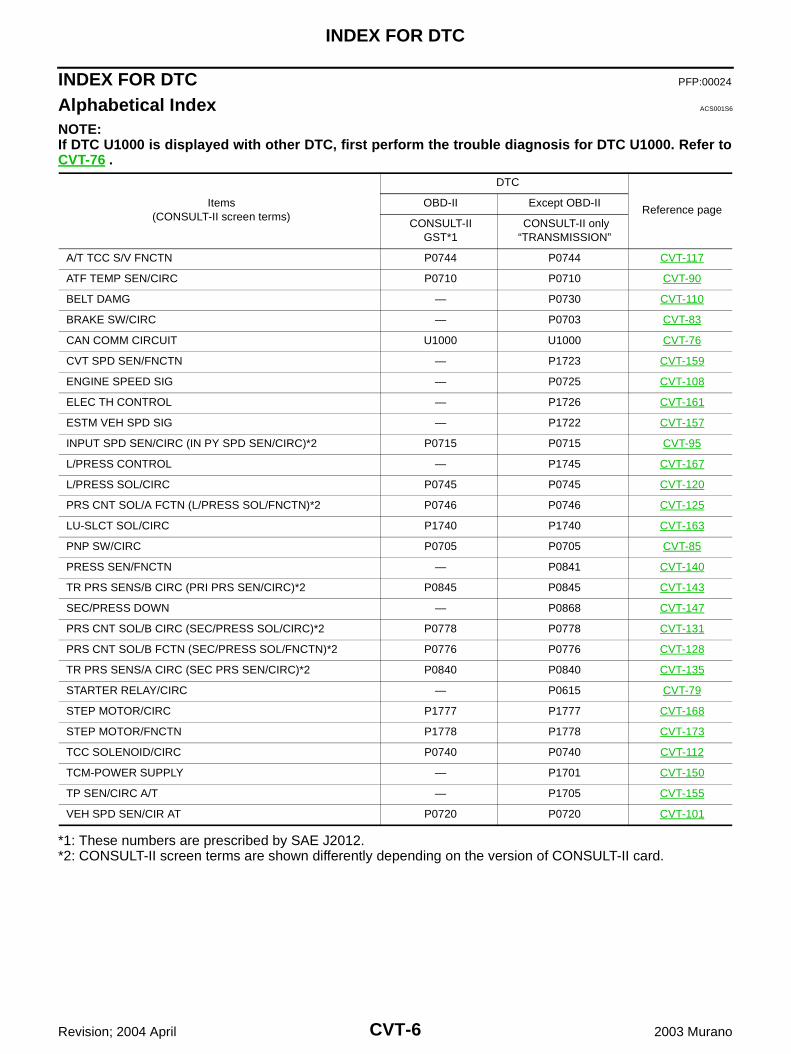
Alphabetical Index ACS001S6
NOTE:If DTC U1000 is displayed with other DTC, first perform the trouble diagnosis for DTC U1000. Refer toCVT-76 .
*1: These numbers are prescribed by SAE J2012.*2: CONSULT-II screen terms are shown differently depending on the version of CONSULT-II card.
Items(CONSULT-II screen terms)
DTC
Reference pageOBD-II Except OBD-II
CONSULT-II GST*1
CONSULT-II only “TRANSMISSION”
A/T TCC S/V FNCTN P0744 P0744 CVT-117
ATF TEMP SEN/CIRC P0710 P0710 CVT-90
BELT DAMG — P0730 CVT-110
BRAKE SW/CIRC — P0703 CVT-83
CAN COMM CIRCUIT U1000 U1000 CVT-76
CVT SPD SEN/FNCTN — P1723 CVT-159
ENGINE SPEED SIG — P0725 CVT-108
ELEC TH CONTROL — P1726 CVT-161
ESTM VEH SPD SIG — P1722 CVT-157
INPUT SPD SEN/CIRC (IN PY SPD SEN/CIRC)*2 P0715 P0715 CVT-95
L/PRESS CONTROL — P1745 CVT-167
L/PRESS SOL/CIRC P0745 P0745 CVT-120
PRS CNT SOL/A FCTN (L/PRESS SOL/FNCTN)*2 P0746 P0746 CVT-125
LU-SLCT SOL/CIRC P1740 P1740 CVT-163
PNP SW/CIRC P0705 P0705 CVT-85
PRESS SEN/FNCTN — P0841 CVT-140
TR PRS SENS/B CIRC (PRI PRS SEN/CIRC)*2 P0845 P0845 CVT-143
SEC/PRESS DOWN — P0868 CVT-147
PRS CNT SOL/B CIRC (SEC/PRESS SOL/CIRC)*2 P0778 P0778 CVT-131
PRS CNT SOL/B FCTN (SEC/PRESS SOL/FNCTN)*2 P0776 P0776 CVT-128
TR PRS SENS/A CIRC (SEC PRS SEN/CIRC)*2 P0840 P0840 CVT-135
STARTER RELAY/CIRC — P0615 CVT-79
STEP MOTOR/CIRC P1777 P1777 CVT-168
STEP MOTOR/FNCTN P1778 P1778 CVT-173
TCC SOLENOID/CIRC P0740 P0740 CVT-112
TCM-POWER SUPPLY — P1701 CVT-150
TP SEN/CIRC A/T — P1705 CVT-155
VEH SPD SEN/CIR AT P0720 P0720 CVT-101
INDEX FOR DTC
CVT-7
D
E
F
G
H
I
J
K
L
M
A
B
CVT
Revision; 2004 April 2003 Murano
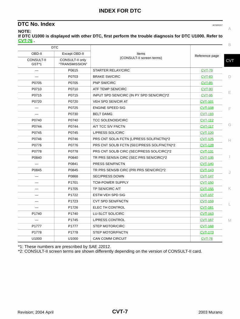
DTC No. Index ACS001S7
NOTE:If DTC U1000 is displayed with other DTC, first perform the trouble diagnosis for DTC U1000. Refer toCVT-76 .
*1: These numbers are prescribed by SAE J2012.*2: CONSULT-II screen terms are shown differently depending on the version of CONSULT-II card.
DTC
Items(CONSULT-II screen terms)
Reference pageOBD-II Except OBD-II
CONSULT-IIGST*1
CONSULT-II only “TRANSMISSION”
— P0615 STARTER RELAY/CIRC CVT-79
— P0703 BRAKE SW/CIRC CVT-83
P0705 P0705 PNP SW/CIRC CVT-85
P0710 P0710 ATF TEMP SEN/CIRC CVT-90
P0715 P0715 INPUT SPD SEN/CIRC (IN PY SPD SEN/CIRC)*2 CVT-95
P0720 P0720 VEH SPD SEN/CIR AT CVT-101
— P0725 ENGINE SPEED SIG CVT-108
— P0730 BELT DAMG CVT-110
P0740 P0740 TCC SOLENOID/CIRC CVT-112
P0744 P0744 A/T TCC S/V FNCTN CVT-117
P0745 P0745 L/PRESS SOL/CIRC CVT-120
P0746 P0746 PRS CNT SOL/A FCTN (L/PRESS SOL/FNCTN)*2 CVT-125
P0776 P0776 PRS CNT SOL/B FCTN (SEC/PRESS SOL/FNCTN)*2 CVT-128
P0778 P0778 PRS CNT SOL/B CIRC (SEC/PRESS SOL/CIRC)*2 CVT-131
P0840 P0840 TR PRS SENS/A CIRC (SEC PRS SEN/CIRC)*2 CVT-135
— P0841 PRESS SEN/FNCTN CVT-140
P0845 P0845 TR PRS SENS/B CIRC (PRI PRS SEN/CIRC)*2 CVT-143
— P0868 SEC/PRESS DOWN CVT-147
— P1701 TCM-POWER SUPPLY CVT-150
— P1705 TP SEN/CIRC A/T CVT-155
— P1722 ESTM VEH SPD SIG CVT-157
— P1723 CVT SPD SEN/FNCTN CVT-159
— P1726 ELEC TH CONTROL CVT-161
P1740 P1740 LU-SLCT SOL/CIRC CVT-163
— P1745 L/PRESS CONTROL CVT-167
P1777 P1777 STEP MOTOR/CIRC CVT-168
P1778 P1778 STEP MOTOR/FNCTN CVT-173
U1000 U1000 CAN COMM CIRCUIT CVT-76
CVT-8
PRECAUTIONS
Revision; 2004 April 2003 Murano
PRECAUTIONS PFP:00001
Precautions for Supplemental Restraint System (SRS) “AIR BAG” and “SEAT BELT PRE-TENSIONER” ACS003KX
The Supplemental Restraint System such as “AIR BAG” and “SEAT BELT PRE-TENSIONER”, used alongwith a front seat belt, helps to reduce the risk or severity of injury to the driver and front passenger for certaintypes of collision. This system includes seat belt switch inputs and dual stage front air bag modules. The SRSsystem uses the seat belt switches to determine the front air bag deployment, and may only deploy one frontair bag, depending on the severity of a collision and whether the front occupants are belted or unbelted.Information necessary to service the system safely is included in the SRS and SB section of this Service Man-ual.WARNING: To avoid rendering the SRS inoperative, which could increase the risk of personal injury or death
in the event of a collision which would result in air bag inflation, all maintenance must be per-formed by an authorized NISSAN/INFINITI dealer.
Improper maintenance, including incorrect removal and installation of the SRS, can lead to per-sonal injury caused by unintentional activation of the system. For removal of Spiral Cable and AirBag Module, see the SRS section.
Do not use electrical test equipment on any circuit related to the SRS unless instructed to in thisService Manual. SRS wiring harnesses can be identified by yellow and/or orange harnesses orharness connectors.
Precautions for TCM and CVT Assembly Replacement ACS001SA
CAUTION: Check if new data (Unit ID) are entered correctly after replacing CVT assembly and erasing data in
TCM. (Connect CONSULT-II, and then turn ignition switch OFF.) When replacing CVT assembly or TCM, refer to the pattern table below and erase the EEPROM in the
TCM if necessary.
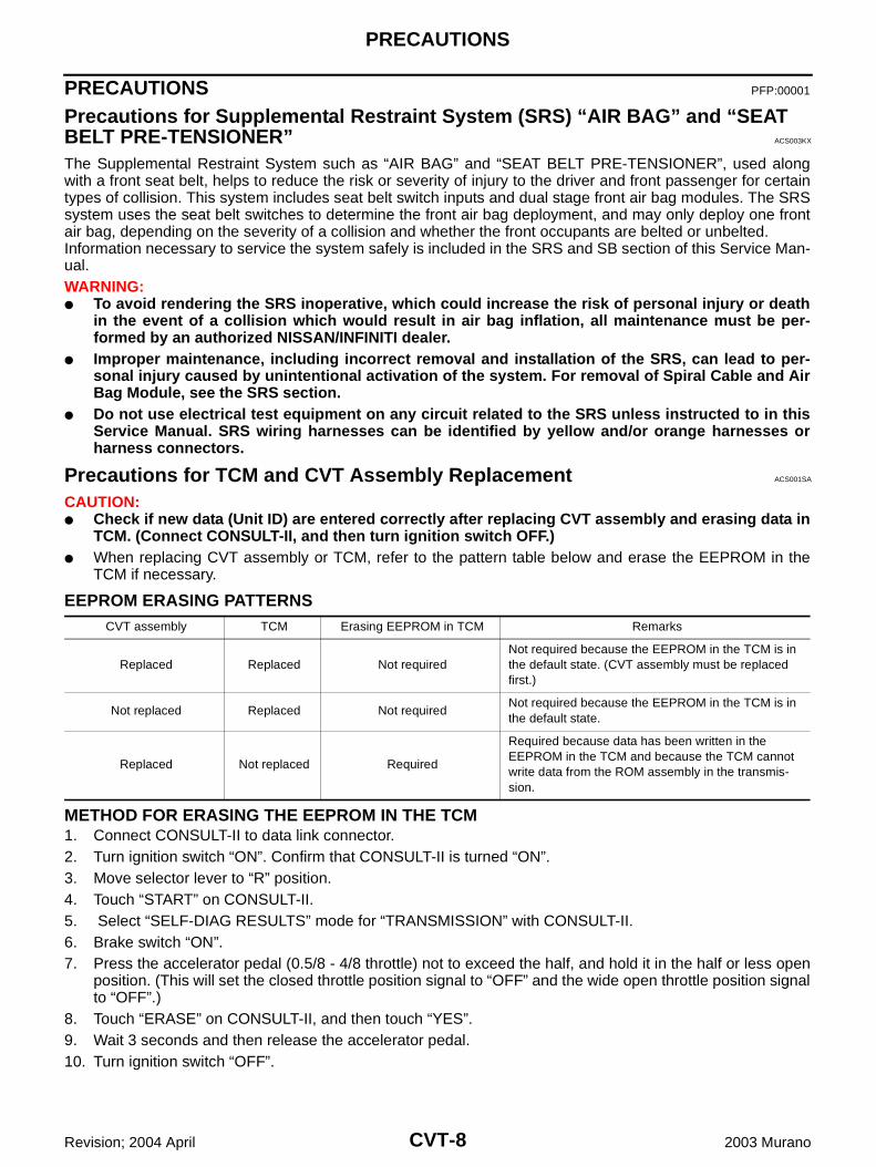
EEPROM ERASING PATTERNS
METHOD FOR ERASING THE EEPROM IN THE TCM1. Connect CONSULT-II to data link connector.2. Turn ignition switch “ON”. Confirm that CONSULT-II is turned “ON”.3. Move selector lever to “R” position.4. Touch “START” on CONSULT-II.5. Select “SELF-DIAG RESULTS” mode for “TRANSMISSION” with CONSULT-II. 6. Brake switch “ON”.7. Press the accelerator pedal (0.5/8 - 4/8 throttle) not to exceed the half, and hold it in the half or less open
position. (This will set the closed throttle position signal to “OFF” and the wide open throttle position signalto “OFF”.)
8. Touch “ERASE” on CONSULT-II, and then touch “YES”.9. Wait 3 seconds and then release the accelerator pedal.10. Turn ignition switch “OFF”.
CVT assembly TCM Erasing EEPROM in TCM Remarks
Replaced Replaced Not requiredNot required because the EEPROM in the TCM is in the default state. (CVT assembly must be replaced first.)
Not replaced Replaced Not requiredNot required because the EEPROM in the TCM is in the default state.
Replaced Not replaced Required
Required because data has been written in the EEPROM in the TCM and because the TCM cannot write data from the ROM assembly in the transmis-sion.
PRECAUTIONS
CVT-9
D
E
F
G
H
I
J
K
L
M
A
B
CVT
Revision; 2004 April 2003 Murano
METHOD FOR WRITING DATA FROM THE ROM ASSEMBLY IN THE TRANSMISSIONIn the following procedure, the TCM reads data from the ROM assembly and writes it to the EEPROM in theTCM.1. With the EEPROM in the TCM erased.2. Move selector lever to “P” position.3. Turn ignition switch “ON”.
CHECK METHOD Normal: About 2 seconds after the ignition is switched to “ON” position, the CVT indicator lamp lights up
for 2 seconds. Non-standard: Even after the ignition is switched to “ON” position, the CVT indicator lamp does not light
up after 2 seconds or illuminates immediately.CAUTION:Perform in the P or N position.
Cope for non-standard Replace the CVT assembly. Replace the TCM.
Removal and Installation Procedure for CVT Unit Connector ACS003L1
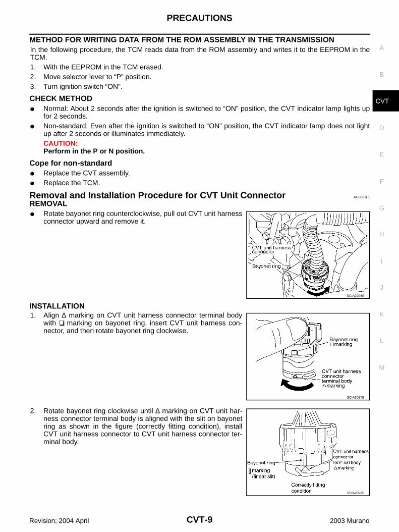
REMOVAL Rotate bayonet ring counterclockwise, pull out CVT unit harness
connector upward and remove it.
INSTALLATION1. Align ∆ marking on CVT unit harness connector terminal body
with marking on bayonet ring, insert CVT unit harness con-nector, and then rotate bayonet ring clockwise.
2. Rotate bayonet ring clockwise until ∆ marking on CVT unit har-ness connector terminal body is aligned with the slit on bayonetring as shown in the figure (correctly fitting condition), installCVT unit harness connector to CVT unit harness connector ter-minal body.
SCIA2096E
SCIA2097E
SCIA2098E
CVT-10
PRECAUTIONS
Revision; 2004 April 2003 Murano
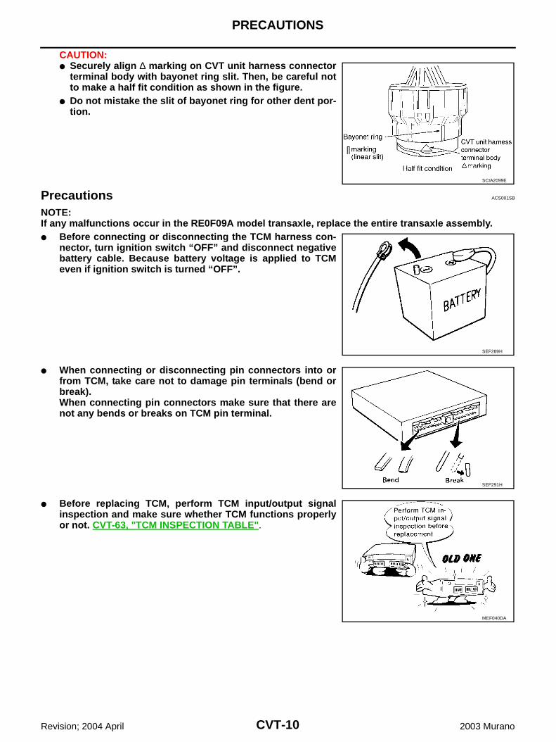
CAUTION: Securely align ∆ marking on CVT unit harness connector
terminal body with bayonet ring slit. Then, be careful notto make a half fit condition as shown in the figure.
Do not mistake the slit of bayonet ring for other dent por-tion.
Precautions ACS001SB
NOTE:If any malfunctions occur in the RE0F09A model transaxle, replace the entire transaxle assembly. Before connecting or disconnecting the TCM harness con-
nector, turn ignition switch “OFF” and disconnect negativebattery cable. Because battery voltage is applied to TCMeven if ignition switch is turned “OFF”.
When connecting or disconnecting pin connectors into orfrom TCM, take care not to damage pin terminals (bend orbreak).When connecting pin connectors make sure that there arenot any bends or breaks on TCM pin terminal.
Before replacing TCM, perform TCM input/output signalinspection and make sure whether TCM functions properlyor not. CVT-63, "TCM INSPECTION TABLE".
SCIA2099E
SEF289H
SEF291H
MEF040DA
PRECAUTIONS
CVT-11
D
E
F
G
H
I
J
K
L
M
A
B
CVT
Revision; 2004 April 2003 Murano
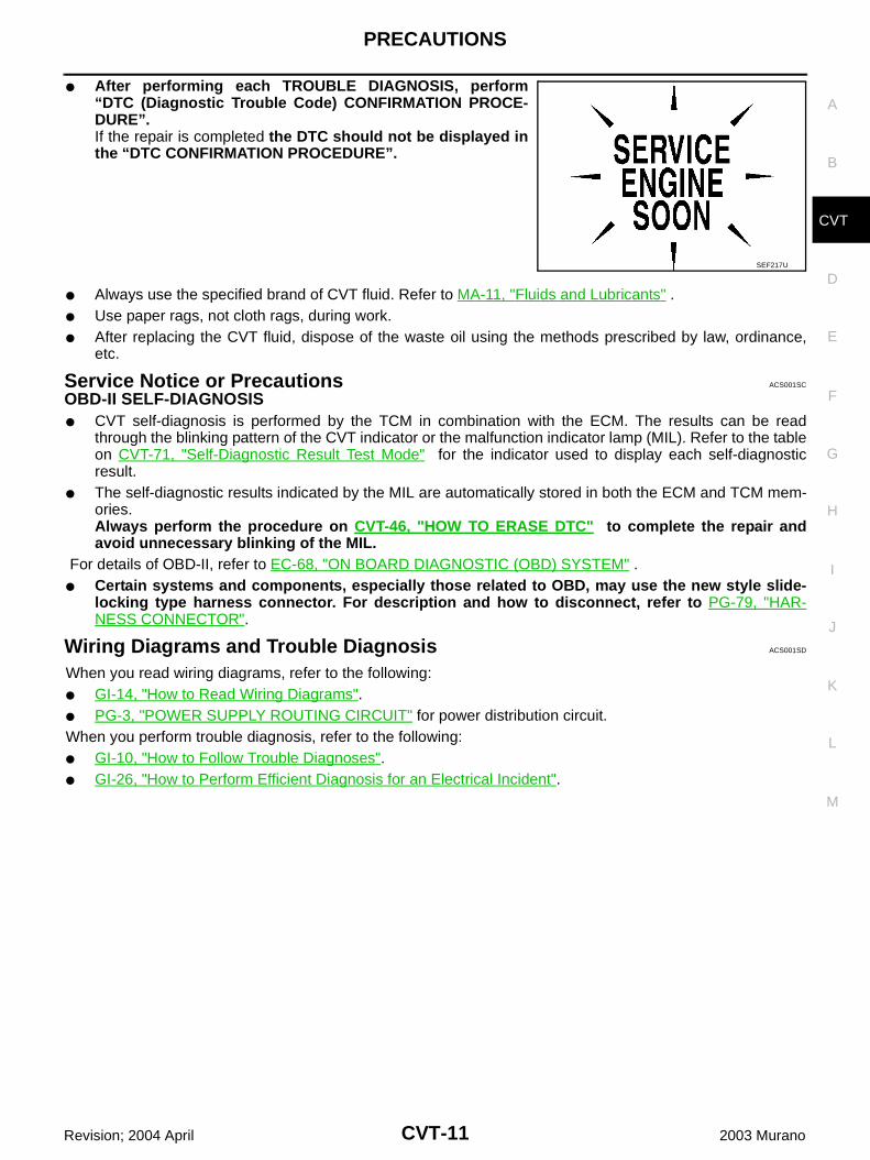
After performing each TROUBLE DIAGNOSIS, perform“DTC (Diagnostic Trouble Code) CONFIRMATION PROCE-DURE”.If the repair is completed the DTC should not be displayed inthe “DTC CONFIRMATION PROCEDURE”.
Always use the specified brand of CVT fluid. Refer to MA-11, "Fluids and Lubricants" . Use paper rags, not cloth rags, during work. After replacing the CVT fluid, dispose of the waste oil using the methods prescribed by law, ordinance,
etc.
Service Notice or Precautions ACS001SC
OBD-II SELF-DIAGNOSIS CVT self-diagnosis is performed by the TCM in combination with the ECM. The results can be read
through the blinking pattern of the CVT indicator or the malfunction indicator lamp (MIL). Refer to the tableon CVT-71, "Self-Diagnostic Result Test Mode" for the indicator used to display each self-diagnosticresult.
The self-diagnostic results indicated by the MIL are automatically stored in both the ECM and TCM mem-ories.Always perform the procedure on CVT-46, "HOW TO ERASE DTC" to complete the repair andavoid unnecessary blinking of the MIL.
For details of OBD-II, refer to EC-68, "ON BOARD DIAGNOSTIC (OBD) SYSTEM" . Certain systems and components, especially those related to OBD, may use the new style slide-
locking type harness connector. For description and how to disconnect, refer to PG-79, "HAR-NESS CONNECTOR".
Wiring Diagrams and Trouble Diagnosis ACS001SD
When you read wiring diagrams, refer to the following: GI-14, "How to Read Wiring Diagrams". PG-3, "POWER SUPPLY ROUTING CIRCUIT" for power distribution circuit.When you perform trouble diagnosis, refer to the following: GI-10, "How to Follow Trouble Diagnoses". GI-26, "How to Perform Efficient Diagnosis for an Electrical Incident".
SEF217U
CVT-12
PREPARATION
Revision; 2004 April 2003 Murano
PREPARATION PFP:00002
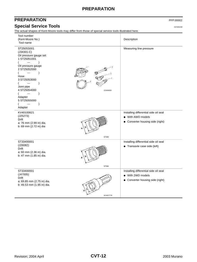
Special Service Tools ACS001SE
The actual shapes of Kent-Moore tools may differ from those of special service tools illustrated here.
Tool number(Kent-Moore No.) Tool name
Description
ST2505S001(J34301-C)Oil pressure gauge set1 ST25051001( — )Oil pressure gauge2 ST25052000( — )Hose3 ST25053000( — )Joint pipe4 ST25054000( — )Adapter5 ST25055000( — )Adapter
Measuring line pressure
KV40100621(J25273)Drifta: 76 mm (2.99 in) dia.b: 69 mm (2.72 in) dia
Installing differential side oil seal
With AWD models
Converter housing side (right)
ST33400001(J26082)Drifta: 60 mm (2.36 in) dia. b: 47 mm (1.85 in) dia.
Installing differential side oil seal
Transaxle case side (left)
ST33400001(J47005)Drifta: 69.85 mm (2.75 in) dia. b: 49.53 mm (1.95 in) dia.
Installing differential side oil seal
With 2WD models
Converter housing side (right)
ZZA0600D
NT086
NT086
SCIA5777E
PREPARATION
CVT-13
D
E
F
G
H
I
J
K
L
M
A
B
CVT
Revision; 2004 April 2003 Murano
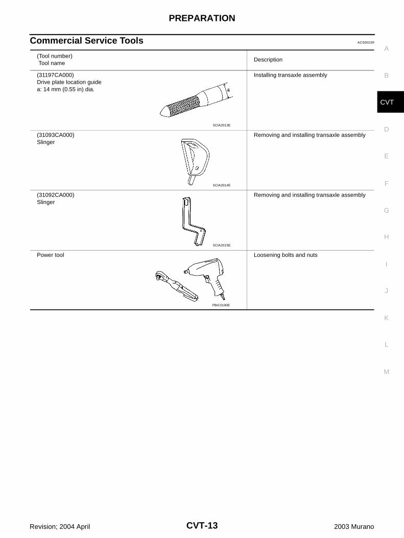
Commercial Service Tools ACS001SF
(Tool number) Tool name
Description
(31197CA000)Drive plate location guidea: 14 mm (0.55 in) dia.
Installing transaxle assembly
(31093CA000)Slinger
Removing and installing transaxle assembly
(31092CA000)Slinger
Removing and installing transaxle assembly
Power tool Loosening bolts and nuts
SCIA2013E
SCIA2014E
SCIA2015E
PBIC0190E
CVT-14
CVT FLUID
Revision; 2004 April 2003 Murano
CVT FLUID PFP:KLE50
Checking CVT Fluid ACS002KW
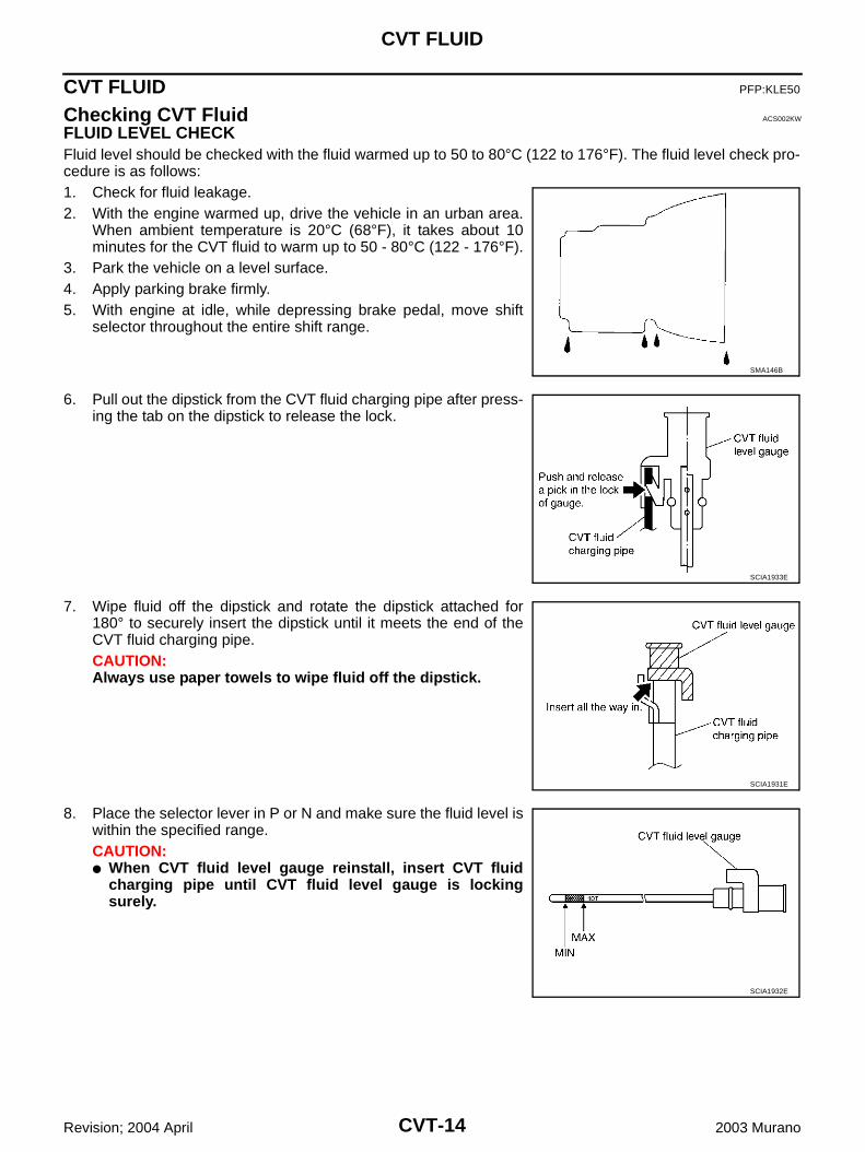
FLUID LEVEL CHECKFluid level should be checked with the fluid warmed up to 50 to 80°C (122 to 176°F). The fluid level check pro-cedure is as follows:1. Check for fluid leakage.2. With the engine warmed up, drive the vehicle in an urban area.
When ambient temperature is 20°C (68°F), it takes about 10minutes for the CVT fluid to warm up to 50 - 80°C (122 - 176°F).
3. Park the vehicle on a level surface.4. Apply parking brake firmly.5. With engine at idle, while depressing brake pedal, move shift
selector throughout the entire shift range.
6. Pull out the dipstick from the CVT fluid charging pipe after press-ing the tab on the dipstick to release the lock.
7. Wipe fluid off the dipstick and rotate the dipstick attached for180° to securely insert the dipstick until it meets the end of theCVT fluid charging pipe.CAUTION:Always use paper towels to wipe fluid off the dipstick.
8. Place the selector lever in P or N and make sure the fluid level iswithin the specified range.CAUTION: When CVT fluid level gauge reinstall, insert CVT fluid
charging pipe until CVT fluid level gauge is lockingsurely.
SMA146B
SCIA1933E
SCIA1931E
SCIA1932E
CVT FLUID
CVT-15
D
E
F
G
H
I
J
K
L
M
A
B
CVT
Revision; 2004 April 2003 Murano
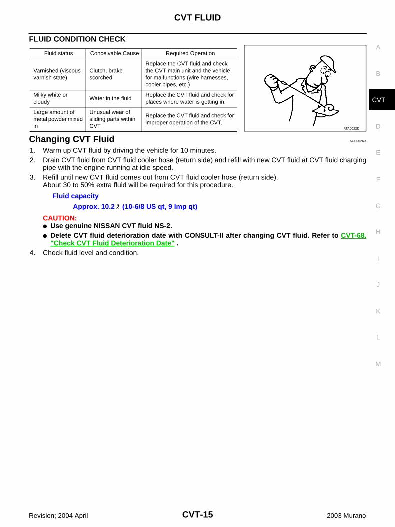
FLUID CONDITION CHECK
Changing CVT Fluid ACS002KX
1. Warm up CVT fluid by driving the vehicle for 10 minutes.2. Drain CVT fluid from CVT fluid cooler hose (return side) and refill with new CVT fluid at CVT fluid charging
pipe with the engine running at idle speed.3. Refill until new CVT fluid comes out from CVT fluid cooler hose (return side).
About 30 to 50% extra fluid will be required for this procedure.
CAUTION: Use genuine NISSAN CVT fluid NS-2. Delete CVT fluid deterioration date with CONSULT-II after changing CVT fluid. Refer to CVT-68,
"Check CVT Fluid Deterioration Date" .4. Check fluid level and condition.
Fluid status Conceivable Cause Required Operation
Varnished (viscous varnish state)
Clutch, brake scorched
Replace the CVT fluid and check the CVT main unit and the vehicle for malfunctions (wire harnesses, cooler pipes, etc.)
Milky white or cloudy
Water in the fluidReplace the CVT fluid and check for places where water is getting in.
Large amount of metal powder mixed in
Unusual wear of sliding parts within CVT
Replace the CVT fluid and check for improper operation of the CVT.
ATA0022D
Fluid capacity
Approx. 10.2 (10-6/8 US qt, 9 lmp qt)
CVT-16
CVT SYSTEM
Revision; 2004 April 2003 Murano
CVT SYSTEM PFP:31036
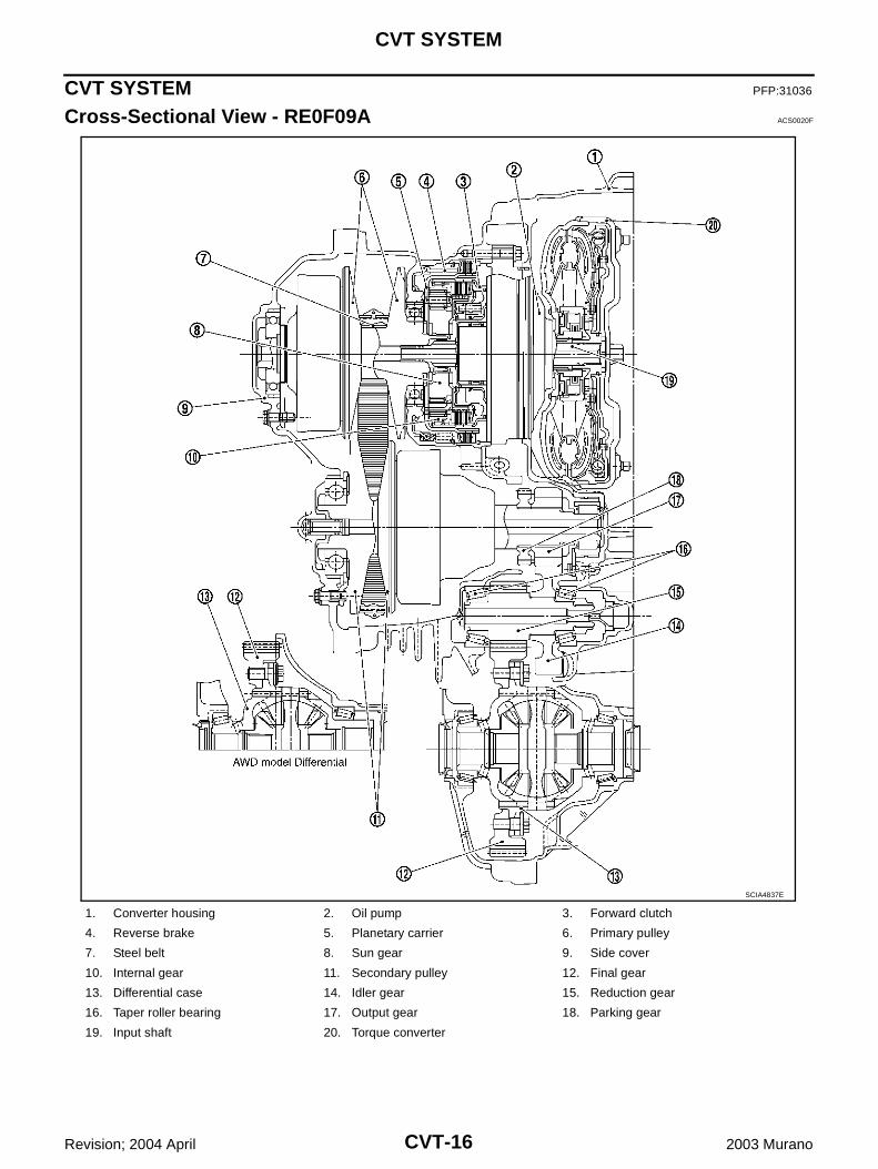
Cross-Sectional View - RE0F09A ACS0020F
1. Converter housing 2. Oil pump 3. Forward clutch
4. Reverse brake 5. Planetary carrier 6. Primary pulley
7. Steel belt 8. Sun gear 9. Side cover
10. Internal gear 11. Secondary pulley 12. Final gear
13. Differential case 14. Idler gear 15. Reduction gear
16. Taper roller bearing 17. Output gear 18. Parking gear
19. Input shaft 20. Torque converter
SCIA4837E
CVT SYSTEM
CVT-17
D
E
F
G
H
I
J
K
L
M
A
B
CVT
Revision; 2004 April 2003 Murano
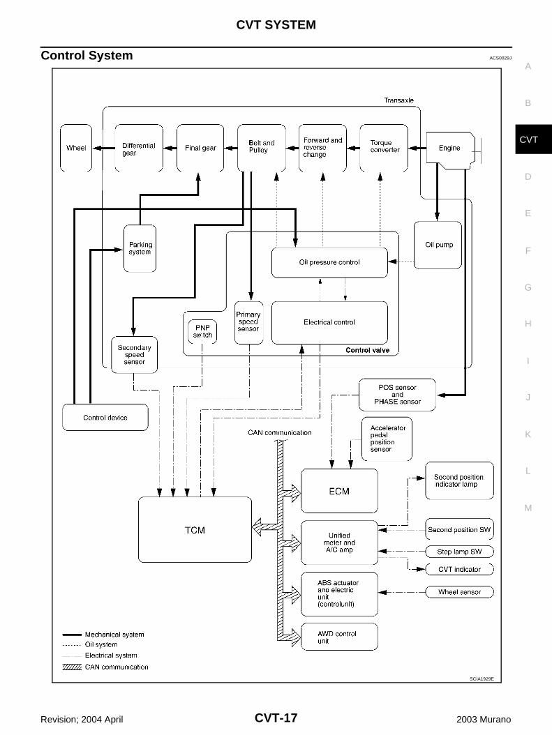
Control System ACS0029J
SCIA1929E
CVT-18
CVT SYSTEM
Revision; 2004 April 2003 Murano
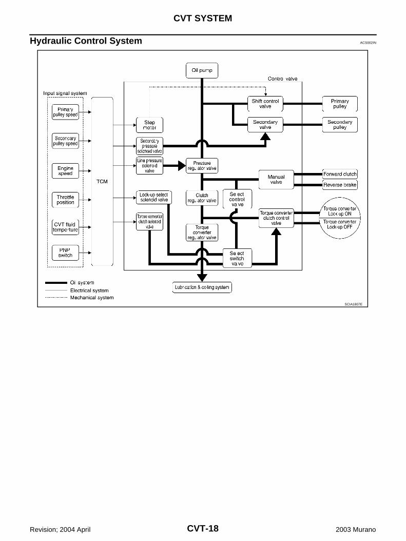
Hydraulic Control System ACS002IN
SCIA1807E
CVT SYSTEM
CVT-19
D
E
F
G
H
I
J
K
L
M
A
B
CVT
Revision; 2004 April 2003 Murano
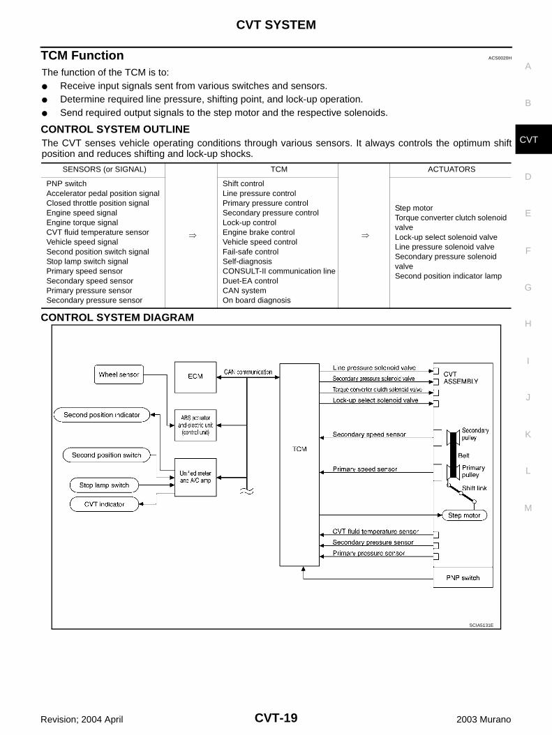
TCM Function ACS0020H
The function of the TCM is to: Receive input signals sent from various switches and sensors. Determine required line pressure, shifting point, and lock-up operation. Send required output signals to the step motor and the respective solenoids.
CONTROL SYSTEM OUTLINE The CVT senses vehicle operating conditions through various sensors. It always controls the optimum shiftposition and reduces shifting and lock-up shocks.
CONTROL SYSTEM DIAGRAM
SENSORS (or SIGNAL)
TCM
ACTUATORS
PNP switchAccelerator pedal position signalClosed throttle position signalEngine speed signalEngine torque signalCVT fluid temperature sensorVehicle speed signalSecond position switch signalStop lamp switch signalPrimary speed sensorSecondary speed sensorPrimary pressure sensorSecondary pressure sensor
Shift controlLine pressure controlPrimary pressure controlSecondary pressure controlLock-up controlEngine brake controlVehicle speed controlFail-safe controlSelf-diagnosisCONSULT-II communication lineDuet-EA controlCAN systemOn board diagnosis
Step motor Torque converter clutch solenoid valveLock-up select solenoid valveLine pressure solenoid valveSecondary pressure solenoid valveSecond position indicator lamp
SCIA5131E
CVT-20
CVT SYSTEM
Revision; 2004 April 2003 Murano
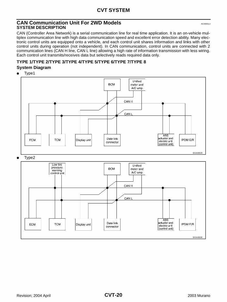
CAN Communication Unit For 2WD Models ACS003L3
SYSTEM DESCRIPTION CAN (Controller Area Network) is a serial communication line for real time application. It is an on-vehicle mul-tiplex communication line with high data communication speed and excellent error detection ability. Many elec-tronic control units are equipped onto a vehicle, and each control unit shares information and links with othercontrol units during operation (not independent). In CAN communication, control units are connected with 2communication lines (CAN H line, CAN L line) allowing a high rate of information transmission with less wiring.Each control unit transmits/receives data but selectively reads required data only.
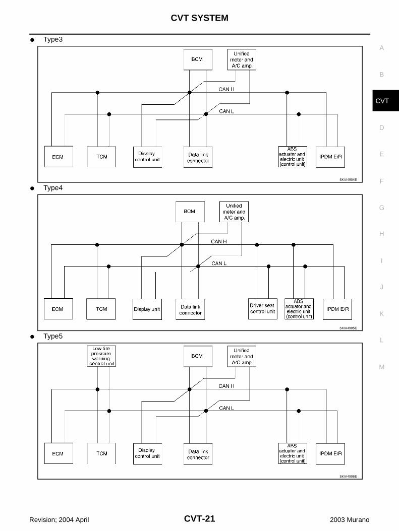
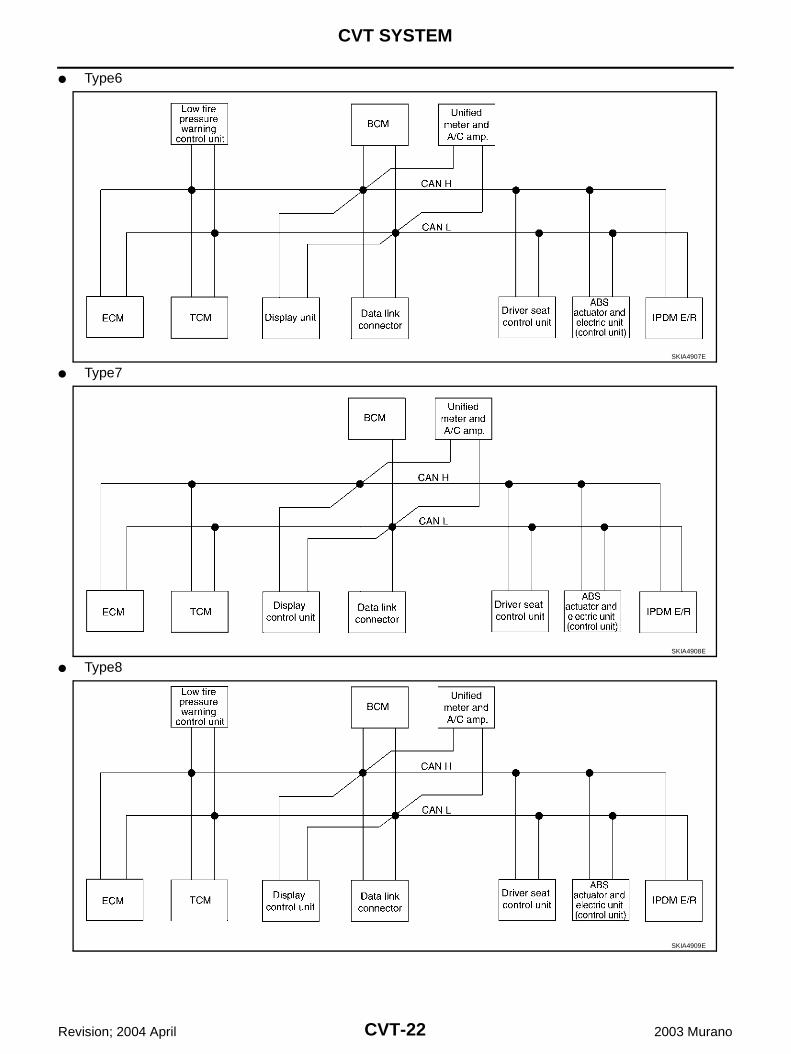
TYPE 1/TYPE 2/TYPE 3/TYPE 4/TYPE 5/TYPE 6/TYPE 7/TYPE 8System Diagram Type1
Type2SKIA4902E
SKIA4903E
CVT SYSTEM
CVT-21
D
E
F
G
H
I
J
K
L
M
A
B
CVT
Revision; 2004 April 2003 Murano
Type3
Type4
Type5
SKIA4904E
SKIA4905E
SKIA4906E
CVT-22
CVT SYSTEM
Revision; 2004 April 2003 Murano
Type6
Type7
Type8
SKIA4907E
SKIA4908E
SKIA4909E
CVT SYSTEM
CVT-23
D
E
F
G
H
I
J
K
L
M
A
B
CVT
Revision; 2004 April 2003 Murano
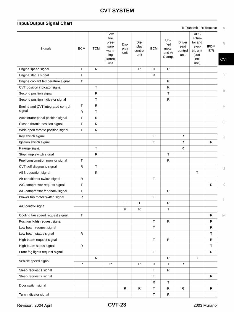
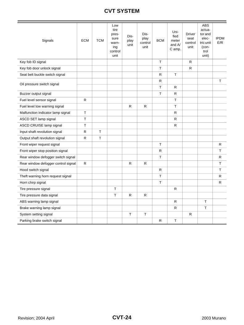
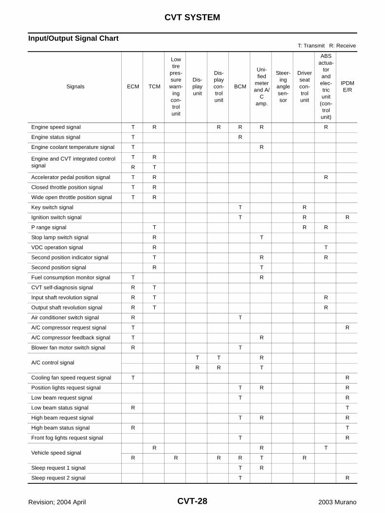
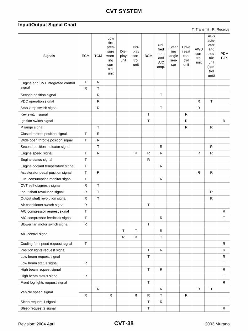
Input/Output Signal ChartT: Transmit R: Receive
Signals ECM TCM
Low tire
pres-sure warn-
ing control
unit
Dis-play unit
Dis-play
control unit
BCM
Uni-fied
meter and A/C amp.
Driver seat
control unit
ABS actua-tor and elec-
tric unit (con-trol
unit)
IPDM E/R
Engine speed signal T R R R R
Engine status signal T R
Engine coolant temperature signal T R
CVT position indicator signal T R
Second position signal R T
Second position indicator signal T R
Engine and CVT integrated control signal
T R
R T
Accelerator pedal position signal T R
Closed throttle position signal T R
Wide open throttle position signal T R
Key switch signal T R
Ignition switch signal T R R
P range signal T R
Stop lamp switch signal R T
Fuel consumption monitor signal T R
CVT self-diagnosis signal R T
ABS operation signal R T
Air conditioner switch signal R T
A/C compressor request signal T R
A/C compressor feedback signal T R
Blower fan motor switch signal R T
A/C control signalT T R
R R T
Cooling fan speed request signal T R
Position lights request signal T R R
Low beam request signal T R
Low beam status signal R T
High beam request signal T R R
High beam status signal R T
Front fog lights request signal T R
Vehicle speed signalR R T
R R R R T R
Sleep request 1 signal T R
Sleep request 2 signal T R
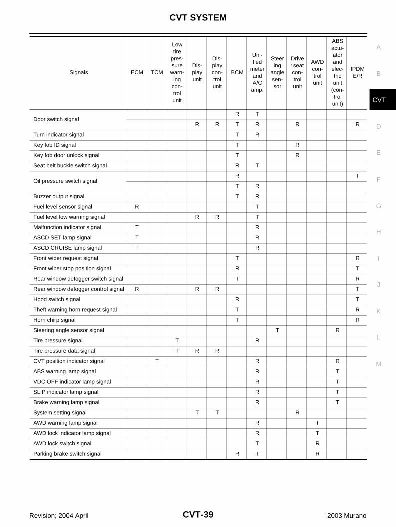
Door switch signalR T
R R T R R R
Turn indicator signal T R
CVT-24
CVT SYSTEM
Revision; 2004 April 2003 Murano
Key fob ID signal T R
Key fob door unlock signal T R
Seat belt buckle switch signal R T
Oil pressure switch signalR T
T R
Buzzer output signal T R
Fuel level sensor signal R T
Fuel level low warning signal R R T
Malfunction indicator lamp signal T R
ASCD SET lamp signal T R
ASCD CRUISE lamp signal T R
Input shaft revolution signal R T
Output shaft revolution signal R T
Front wiper request signal T R
Front wiper stop position signal R T
Rear window defogger switch signal T R
Rear window defogger control signal R R R T
Hood switch signal R T
Theft warning horn request signal T R
Horn chirp signal T R
Tire pressure signal T R
Tire pressure data signal T R R
ABS warning lamp signal R T
Brake warning lamp signal R T
System setting signal T T R
Parking brake switch signal R T
Signals ECM TCM
Low tire
pres-sure
warn-ing
control unit
Dis-play unit
Dis-play
control unit
BCM
Uni-fied
meter and A/C amp.
Driver seat
control unit
ABS actua-tor and elec-
tric unit (con-trol
unit)
IPDM E/R
CVT SYSTEM
CVT-25
D
E
F
G
H
I
J
K
L
M
A
B
CVT
Revision; 2004 April 2003 Murano
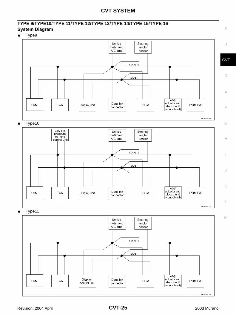
TYPE 9/TYPE10/TYPE 11/TYPE 12/TYPE 13/TYPE 14/TYPE 15/TYPE 16System Diagram Type9
Type10
Type11
SKIA4910E
SKIA4911E
SKIA4912E
CVT-26
CVT SYSTEM
Revision; 2004 April 2003 Murano
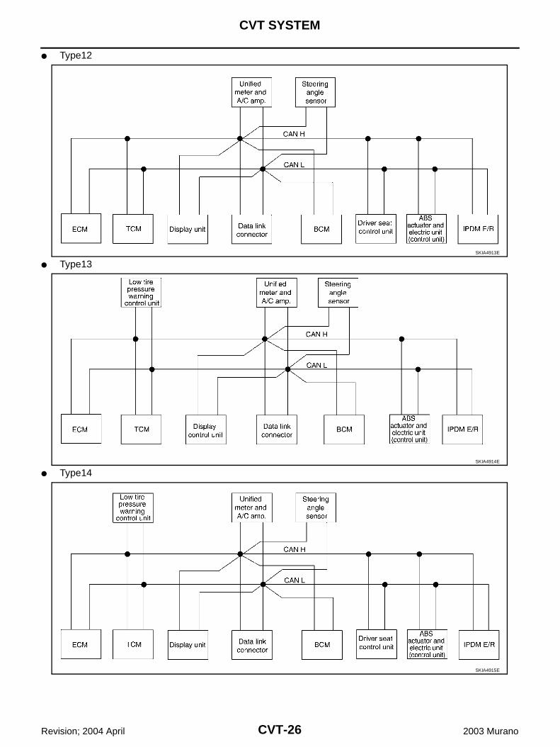
Type12
Type13
Type14
SKIA4913E
SKIA4914E
SKIA4915E
CVT SYSTEM
CVT-27
D
E
F
G
H
I
J
K
L
M
A
B
CVT
Revision; 2004 April 2003 Murano
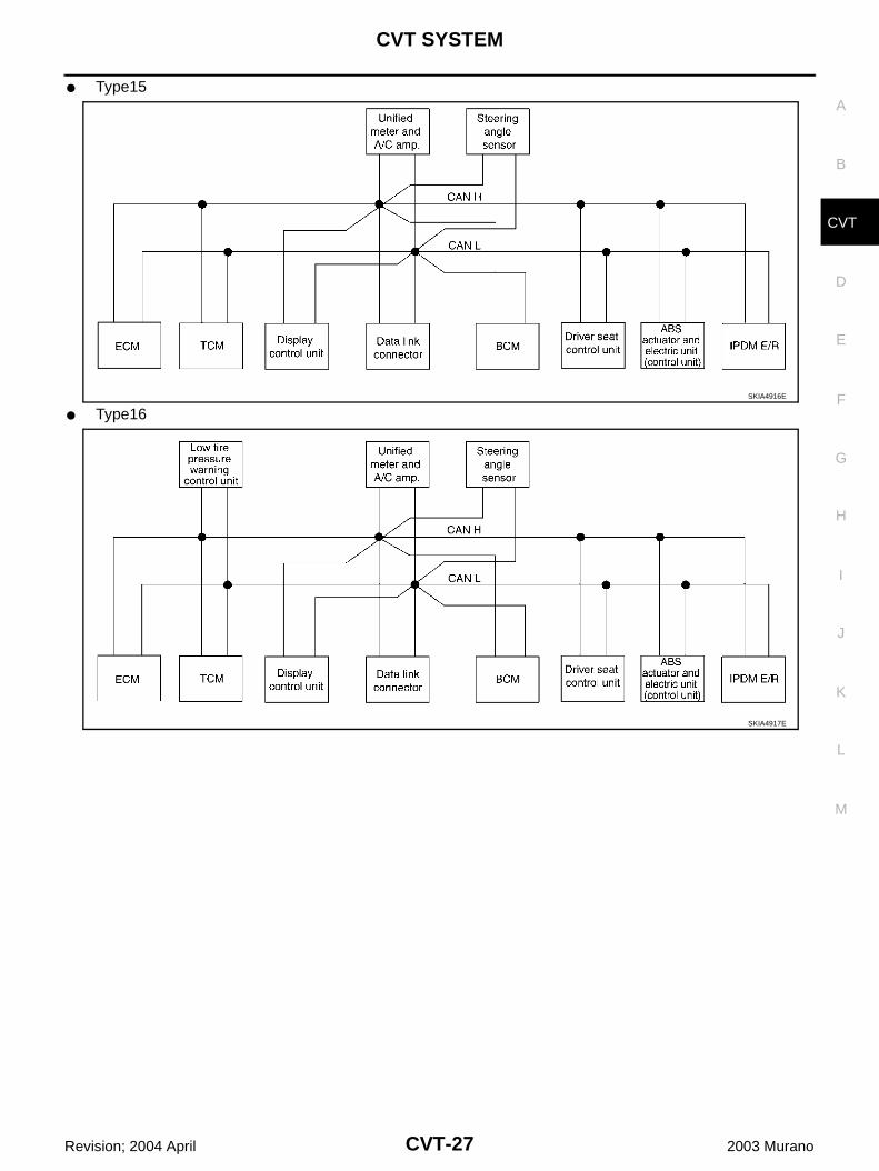
Type15
Type16SKIA4916E
SKIA4917E
CVT-28
CVT SYSTEM
Revision; 2004 April 2003 Murano
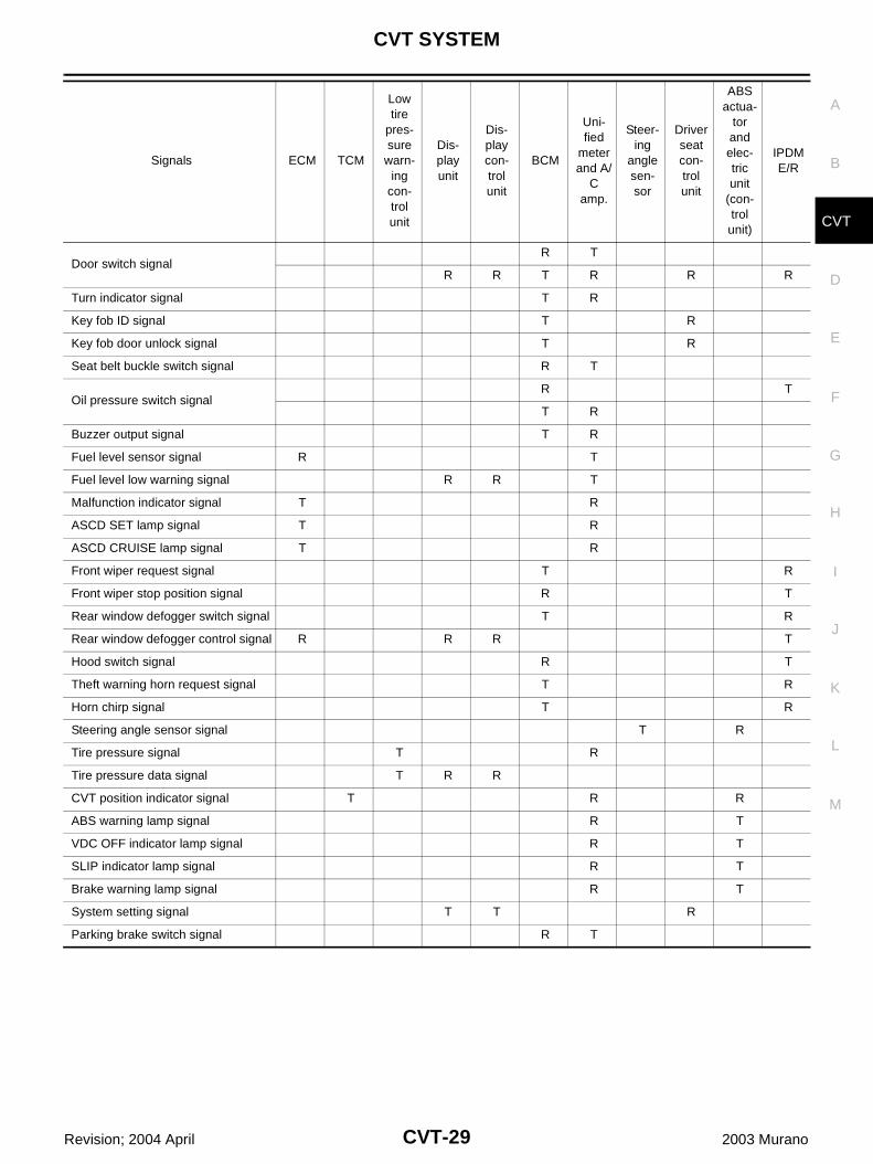
Input/Output Signal ChartT: Transmit R: Receive
Signals ECM TCM
Low tire
pres-sure warn-
ing con-trol unit
Dis-play unit
Dis-play con-trol unit
BCM
Uni-fied
meter and A/
C amp.
Steer-ing
angle sen-sor
Driver seat con-trol unit
ABS actua-
tor and elec-tric unit
(con-trol
unit)
IPDM E/R
Engine speed signal T R R R R R
Engine status signal T R
Engine coolant temperature signal T R
Engine and CVT integrated control signal
T R
R T
Accelerator pedal position signal T R R
Closed throttle position signal T R
Wide open throttle position signal T R
Key switch signal T R
Ignition switch signal T R R
P range signal T R R
Stop lamp switch signal R T
VDC operation signal R T
Second position indicator signal T R R
Second position signal R T
Fuel consumption monitor signal T R
CVT self-diagnosis signal R T
Input shaft revolution signal R T R
Output shaft revolution signal R T R
Air conditioner switch signal R T
A/C compressor request signal T R
A/C compressor feedback signal T R
Blower fan motor switch signal R T
A/C control signalT T R
R R T
Cooling fan speed request signal T R
Position lights request signal T R R
Low beam request signal T R
Low beam status signal R T
High beam request signal T R R
High beam status signal R T
Front fog lights request signal T R
Vehicle speed signalR R T
R R R R T R
Sleep request 1 signal T R
Sleep request 2 signal T R
CVT SYSTEM
CVT-29
D
E
F
G
H
I
J
K
L
M
A
B
CVT
Revision; 2004 April 2003 Murano
Door switch signalR T
R R T R R R
Turn indicator signal T R
Key fob ID signal T R
Key fob door unlock signal T R
Seat belt buckle switch signal R T
Oil pressure switch signalR T
T R
Buzzer output signal T R
Fuel level sensor signal R T
Fuel level low warning signal R R T
Malfunction indicator signal T R
ASCD SET lamp signal T R
ASCD CRUISE lamp signal T R
Front wiper request signal T R
Front wiper stop position signal R T
Rear window defogger switch signal T R
Rear window defogger control signal R R R T
Hood switch signal R T
Theft warning horn request signal T R
Horn chirp signal T R
Steering angle sensor signal T R
Tire pressure signal T R
Tire pressure data signal T R R
CVT position indicator signal T R R
ABS warning lamp signal R T
VDC OFF indicator lamp signal R T
SLIP indicator lamp signal R T
Brake warning lamp signal R T
System setting signal T T R
Parking brake switch signal R T
Signals ECM TCM
Low tire
pres-sure
warn-ing
con-trol unit
Dis-play unit
Dis-play con-trol unit
BCM
Uni-fied
meter and A/
C amp.
Steer-ing
angle sen-sor
Driver seat con-trol unit
ABS actua-
tor and elec-tric unit
(con-trol unit)
IPDM E/R
CVT-30
CVT SYSTEM
Revision; 2004 April 2003 Murano
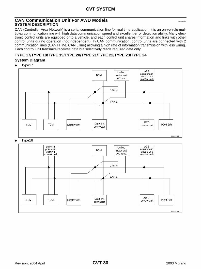
CAN Communication Unit For AWD Models ACS003L4
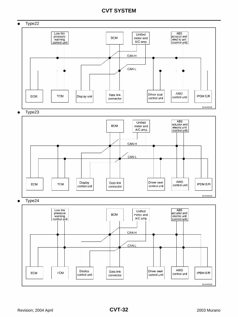
SYSTEM DESCRIPTION CAN (Controller Area Network) is a serial communication line for real time application. It is an on-vehicle mul-tiplex communication line with high data communication speed and excellent error detection ability. Many elec-tronic control units are equipped onto a vehicle, and each control unit shares information and links with othercontrol units during operation (not independent). In CAN communication, control units are connected with 2communication lines (CAN H line, CAN L line) allowing a high rate of information transmission with less wiring.Each control unit transmits/receives data but selectively reads required data only.
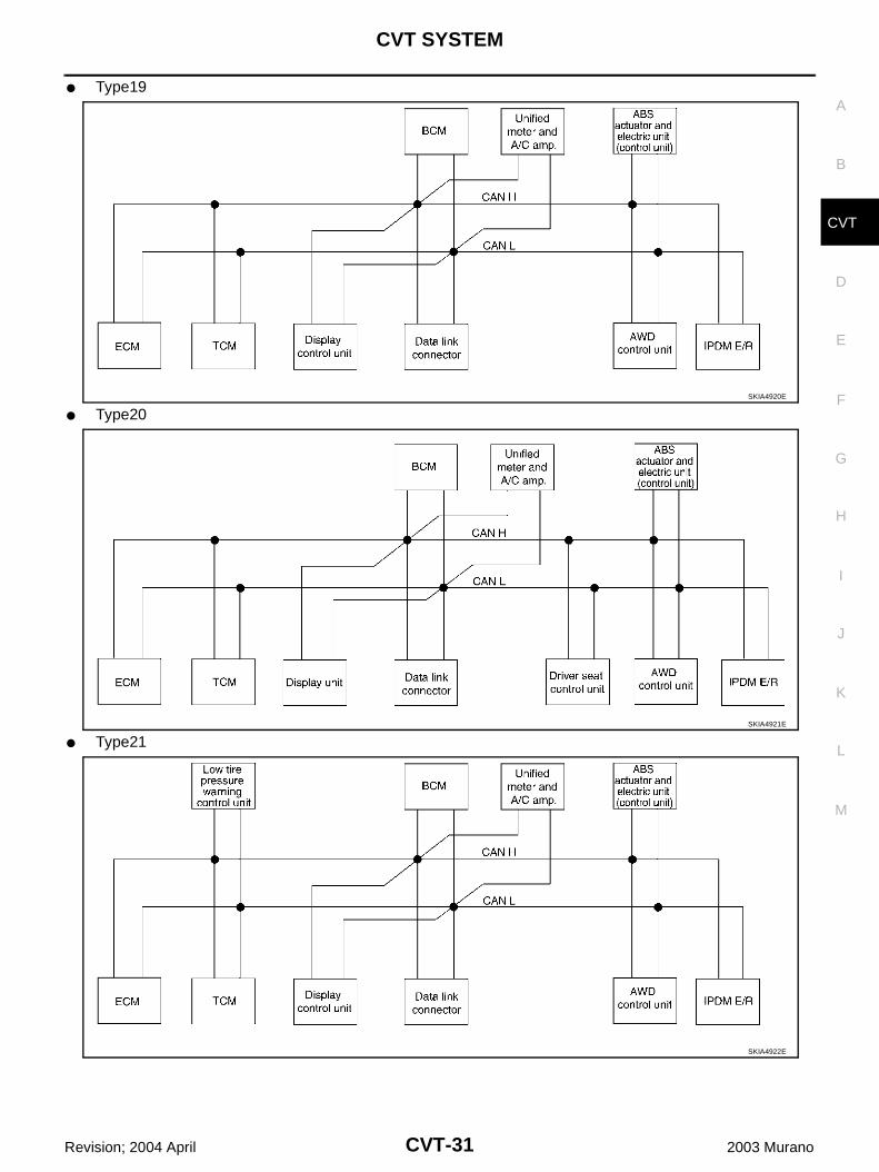
TYPE 17/TYPE 18/TYPE 19/TYPE 20/TYPE 21/TYPE 22/TYPE 23/TYPE 24System Diagram Type17
Type18SKIA4918E
SKIA4919E
CVT SYSTEM
CVT-31
D
E
F
G
H
I
J
K
L
M
A
B
CVT
Revision; 2004 April 2003 Murano
Type19
Type20
Type21
SKIA4920E
SKIA4921E
SKIA4922E
CVT-32
CVT SYSTEM
Revision; 2004 April 2003 Murano
Type22
Type23
Type24
SKIA4923E
SKIA4924E
SKIA4925E
CVT SYSTEM
CVT-33
D
E
F
G
H
I
J
K
L
M
A
B
CVT
Revision; 2004 April 2003 Murano
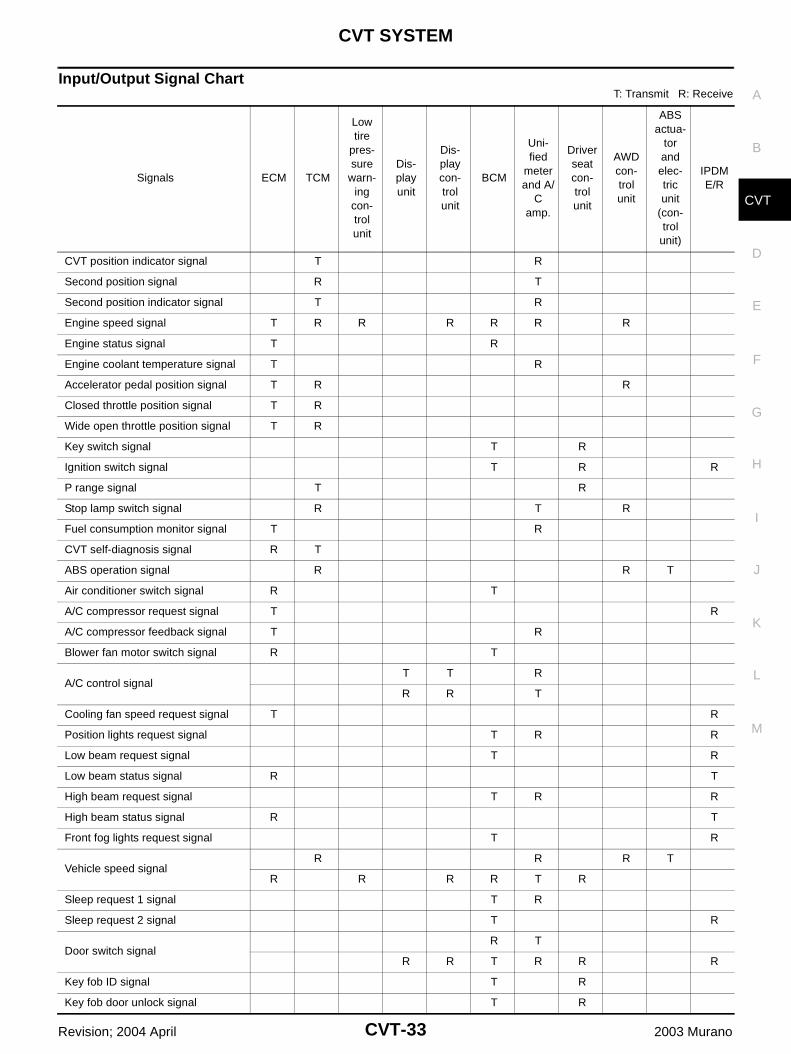
Input/Output Signal ChartT: Transmit R: Receive
Signals ECM TCM
Low tire
pres-sure
warn-ing
con-trol unit
Dis-play unit
Dis-play con-trol unit
BCM
Uni-fied
meter and A/
C amp.
Driver seat con-trol unit
AWD con-trol unit
ABS actua-
tor and elec-tric unit
(con-trol
unit)
IPDM E/R
CVT position indicator signal T R
Second position signal R T
Second position indicator signal T R
Engine speed signal T R R R R R R
Engine status signal T R
Engine coolant temperature signal T R
Accelerator pedal position signal T R R
Closed throttle position signal T R
Wide open throttle position signal T R
Key switch signal T R
Ignition switch signal T R R
P range signal T R
Stop lamp switch signal R T R
Fuel consumption monitor signal T R
CVT self-diagnosis signal R T
ABS operation signal R R T
Air conditioner switch signal R T
A/C compressor request signal T R
A/C compressor feedback signal T R
Blower fan motor switch signal R T
A/C control signalT T R
R R T
Cooling fan speed request signal T R
Position lights request signal T R R
Low beam request signal T R
Low beam status signal R T
High beam request signal T R R
High beam status signal R T
Front fog lights request signal T R
Vehicle speed signalR R R T
R R R R T R
Sleep request 1 signal T R
Sleep request 2 signal T R
Door switch signalR T
R R T R R R
Key fob ID signal T R
Key fob door unlock signal T R

CVT-34
CVT SYSTEM
Revision; 2004 April 2003 Murano
Turn indicator signal T R
Seat belt buckle switch signal R T
Oil pressure switch signalR T
T R
Buzzer output signal T R
Fuel level sensor signal R T
Fuel level low warning signal R R T
Malfunction indicator lamp signal T R
ASCD SET lamp signal T R
ASCD CRUISE lamp signal T R
Input shaft revolution signal R T
Output shaft revolution signal R T
Front wiper request signal T R
Front wiper stop position signal R T
Rear window defogger switch signal T R
Rear window defogger control signal R R R T
Engine and CVT integrated control signal
T R
R T
Hood switch signal R T
Theft warning horn request signal T R
Horn chirp signal T R
Tire pressure signal T R
Tire pressure data signal T R R
ABS warning lamp signal R T
Brake warning lamp signal R T
System setting signal T T R
AWD warning lamp signal R T
AWD lock indicator lamp signal R T
AWD lock switch signal T R
Parking brake switch signal R T R
Signals ECM TCM
Low tire
pres-sure warn-
ing con-trol unit
Dis-play unit
Dis-play con-trol unit
BCM
Uni-fied
meter and A/
C amp.
Driver seat con-trol unit
AWD con-trol unit
ABS actua-
tor and elec-tric unit
(con-trol unit)
IPDM E/R
CVT SYSTEM
CVT-35
D
E
F
G
H
I
J
K
L
M
A
B
CVT
Revision; 2004 April 2003 Murano
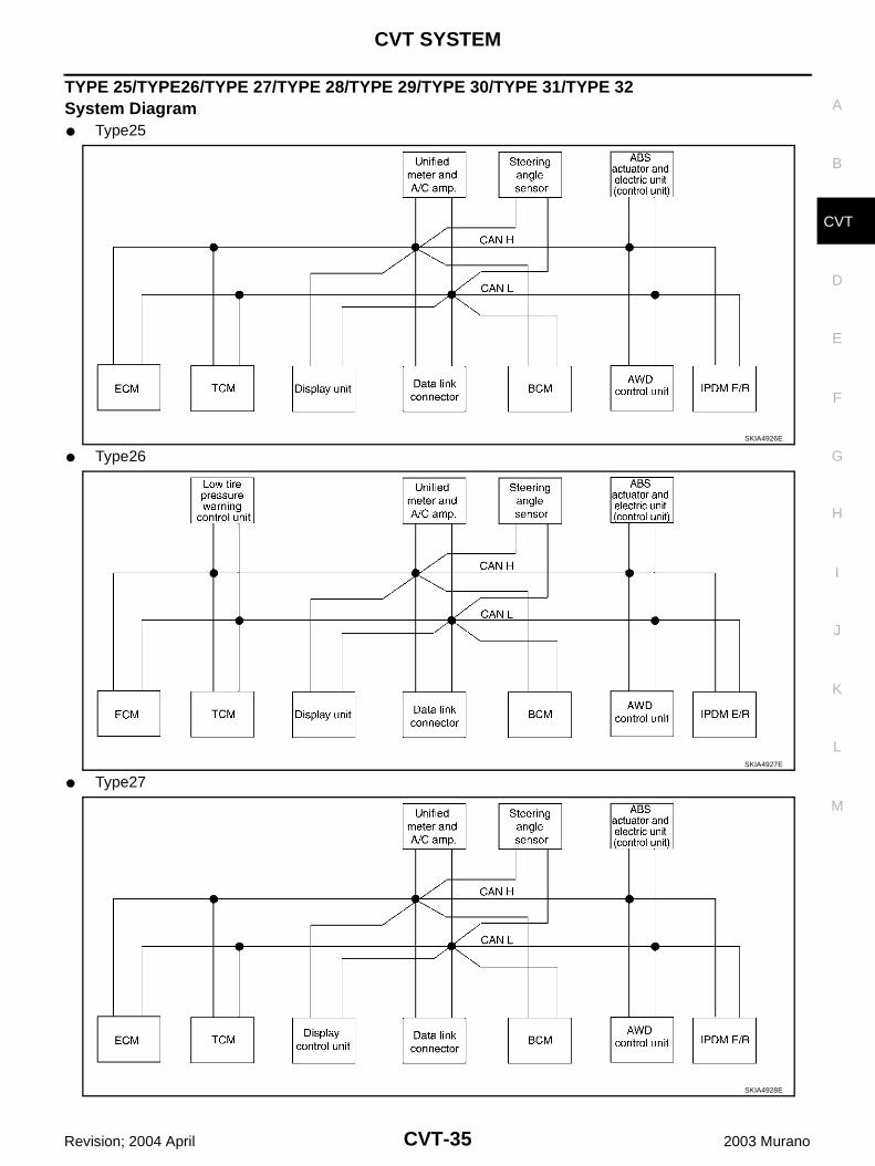
TYPE 25/TYPE26/TYPE 27/TYPE 28/TYPE 29/TYPE 30/TYPE 31/TYPE 32System Diagram Type25
Type26
Type27
SKIA4926E
SKIA4927E
SKIA4928E
CVT-36
CVT SYSTEM
Revision; 2004 April 2003 Murano
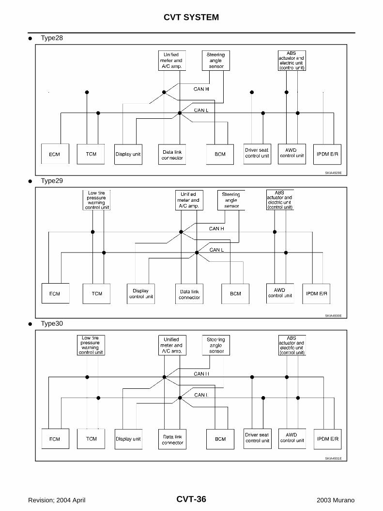
Type28
Type29
Type30
SKIA4929E
SKIA4930E
SKIA4931E

CVT SYSTEM
CVT-37
D
E
F
G
H
I
J
K
L
M
A
B
CVT
Revision; 2004 April 2003 Murano
Type31
Type32SKIA4932E
SKIA4933E
CVT-38
CVT SYSTEM
Revision; 2004 April 2003 Murano
Input/Output Signal ChartT: Transmit R: Receive
Signals ECM TCM
Low tire
pres-sure warn-
ing con-trol unit
Dis-play unit
Dis-play con-trol unit
BCM
Uni-fied
meter and A/C
amp.
Steering
angle sen-sor
Driver seat con-trol unit
AWD con-trol unit
ABS actu-ator and elec-tric unit
(con-trol unit)
IPDM E/R
Engine and CVT integrated control signal
T R
R T
Second position signal R T
VDC operation signal R R T
Stop lamp switch signal R T R
Key switch signal T R
Ignition switch signal T R R
P range signal T R R
Closed throttle position signal T R
Wide open throttle position signal T R
Second position indicator signal T R R
Engine speed signal T R R R R R R
Engine status signal T R
Engine coolant temperature signal T R
Accelerator pedal position signal T R R R
Fuel consumption monitor signal T R
CVT self-diagnosis signal R T
Input shaft revolution signal R T R
Output shaft revolution signal R T R
Air conditioner switch signal R T
A/C compressor request signal T R
A/C compressor feedback signal T R T
Blower fan motor switch signal R T
A/C control signalT T R
R R T
Cooling fan speed request signal T R
Position lights request signal T R R
Low beam request signal T R
Low beam status signal R T
High beam request signal T R R
High beam status signal R T
Front fog lights request signal T R
Vehicle speed signalR R R T
R R R R T R
Sleep request 1 signal T R
Sleep request 2 signal T R
CVT SYSTEM
CVT-39
D
E
F
G
H
I
J
K
L
M
A
B
CVT
Revision; 2004 April 2003 Murano
Door switch signalR T
R R T R R R
Turn indicator signal T R
Key fob ID signal T R
Key fob door unlock signal T R
Seat belt buckle switch signal R T
Oil pressure switch signalR T
T R
Buzzer output signal T R
Fuel level sensor signal R T
Fuel level low warning signal R R T
Malfunction indicator signal T R
ASCD SET lamp signal T R
ASCD CRUISE lamp signal T R
Front wiper request signal T R
Front wiper stop position signal R T
Rear window defogger switch signal T R
Rear window defogger control signal R R R T
Hood switch signal R T
Theft warning horn request signal T R
Horn chirp signal T R
Steering angle sensor signal T R
Tire pressure signal T R
Tire pressure data signal T R R
CVT position indicator signal T R R
ABS warning lamp signal R T
VDC OFF indicator lamp signal R T
SLIP indicator lamp signal R T
Brake warning lamp signal R T
System setting signal T T R
AWD warning lamp signal R T
AWD lock indicator lamp signal R T
AWD lock switch signal T R
Parking brake switch signal R T R
Signals ECM TCM
Low tire
pres-sure
warn-ing
con-trol unit
Dis-play unit
Dis-play con-trol unit
BCM
Uni-fied
meter and A/C
amp.
Steering
angle sen-sor
Driver seat con-trol unit
AWD con-trol unit
ABS actu-ator and elec-tric unit
(con-trol
unit)
IPDM E/R
CVT-40
CVT SYSTEM
Revision; 2004 April 2003 Murano
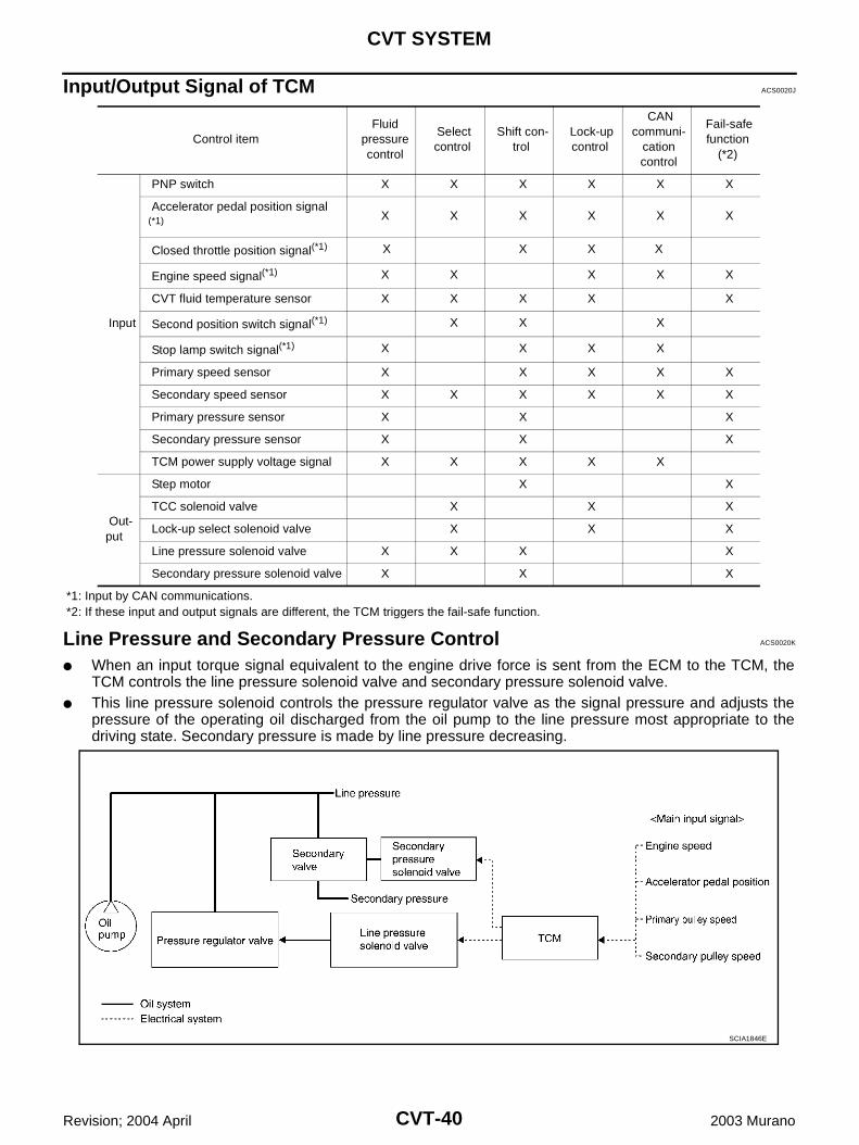
Input/Output Signal of TCM ACS0020J
*1: Input by CAN communications. *2: If these input and output signals are different, the TCM triggers the fail-safe function.
Line Pressure and Secondary Pressure Control ACS0020K
When an input torque signal equivalent to the engine drive force is sent from the ECM to the TCM, theTCM controls the line pressure solenoid valve and secondary pressure solenoid valve.
This line pressure solenoid controls the pressure regulator valve as the signal pressure and adjusts thepressure of the operating oil discharged from the oil pump to the line pressure most appropriate to thedriving state. Secondary pressure is made by line pressure decreasing.
Control item Fluid
pressure control
Select control
Shift con-trol
Lock-up control
CAN communi-
cation control
Fail-safe function
(*2)
Input
PNP switch X X X X X X
Accelerator pedal position signal (*1) X X X X X X
Closed throttle position signal(*1) X X X X
Engine speed signal(*1) X X X X X
CVT fluid temperature sensor X X X X X
Second position switch signal(*1) X X X
Stop lamp switch signal(*1) X X X X
Primary speed sensor X X X X X
Secondary speed sensor X X X X X X
Primary pressure sensor X X X
Secondary pressure sensor X X X
TCM power supply voltage signal X X X X X
Out-put
Step motor X X
TCC solenoid valve X X X
Lock-up select solenoid valve X X X
Line pressure solenoid valve X X X X
Secondary pressure solenoid valve X X X
SCIA1846E
CVT SYSTEM
CVT-41
D
E
F
G
H
I
J
K
L
M
A
B
CVT
Revision; 2004 April 2003 Murano
NORMAL CONTROLOptimize the line pressure and secondary pressure, depending on driving conditions, on the basis of the throt-tle position, the engine speed, the primary pulley (input) revolution speed, the secondary pulley (output) revo-lution speed, the brake signal, the PNP switch signal, the lock-up signal, the voltage, the target gear ratio, thefluid temperature, and the fluid pressure.
FEEDBACK CONTROL When controlling the normal fluid pressure or the selected fluid pressure, the secondary pressure can be setmore accurately by using the fluid pressure sensor to detect the secondary pressure and controlling the feed-back.
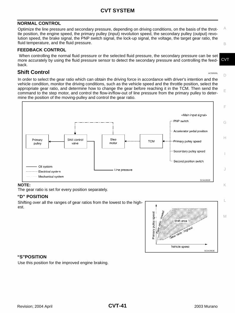
Shift Control ACS0020L
In order to select the gear ratio which can obtain the driving force in accordance with driver's intention and thevehicle condition, monitor the driving conditions, such as the vehicle speed and the throttle position, select theappropriate gear ratio, and determine how to change the gear before reaching it in the TCM. Then send thecommand to the step motor, and control the flow-in/flow-out of line pressure from the primary pulley to deter-mine the position of the moving-pulley and control the gear ratio.
NOTE:The gear ratio is set for every position separately.
“D” POSITIONShifting over all the ranges of gear ratios from the lowest to the high-est.
“S”POSITIONUse this position for the improved engine braking.
SCIA1952E
SCIA1953E
CVT-42
CVT SYSTEM
Revision; 2004 April 2003 Murano
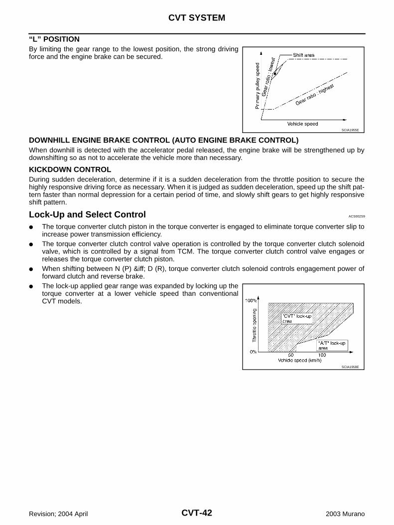
“L” POSITIONBy limiting the gear range to the lowest position, the strong drivingforce and the engine brake can be secured.
DOWNHILL ENGINE BRAKE CONTROL (AUTO ENGINE BRAKE CONTROL)When downhill is detected with the accelerator pedal released, the engine brake will be strengthened up bydownshifting so as not to accelerate the vehicle more than necessary.
KICKDOWN CONTROLDuring sudden deceleration, determine if it is a sudden deceleration from the throttle position to secure thehighly responsive driving force as necessary. When it is judged as sudden deceleration, speed up the shift pat-tern faster than normal depression for a certain period of time, and slowly shift gears to get highly responsiveshift pattern.
Lock-Up and Select Control ACS002S9
The torque converter clutch piston in the torque converter is engaged to eliminate torque converter slip toincrease power transmission efficiency.
The torque converter clutch control valve operation is controlled by the torque converter clutch solenoidvalve, which is controlled by a signal from TCM. The torque converter clutch control valve engages orreleases the torque converter clutch piston.
When shifting between N (P) ⇔ D (R), torque converter clutch solenoid controls engagement power offorward clutch and reverse brake.
The lock-up applied gear range was expanded by locking up thetorque converter at a lower vehicle speed than conventionalCVT models.
SCIA1955E
SCIA1958E
CVT SYSTEM
CVT-43
D
E
F
G
H
I
J
K
L
M
A
B
CVT
Revision; 2004 April 2003 Murano
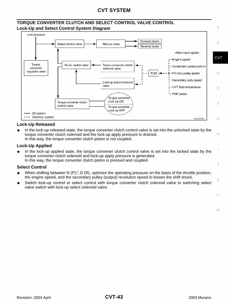
TORQUE CONVERTER CLUTCH AND SELECT CONTROL VALVE CONTROL Lock-Up and Select Control System Diagram
Lock-Up Released In the lock-up released state, the torque converter clutch control valve is set into the unlocked state by the
torque converter clutch solenoid and the lock-up apply pressure is drained.In this way, the torque converter clutch piston is not coupled.
Lock-Up Applied In the lock-up applied state, the torque converter clutch control valve is set into the locked state by the
torque converter clutch solenoid and lock-up apply pressure is generated.In this way, the torque converter clutch piston is pressed and coupled.
Select Control When shifting between N (P)⇔D (R), optimize the operating pressure on the basis of the throttle position,
the engine speed, and the secondary pulley (output) revolution speed to lessen the shift shock. Switch lock-up control or select control with torque converter clutch solenoid valve to switching select
valve switch with lock-up select solenoid valve.
SCIA2374E
CVT-44
CVT SYSTEM
Revision; 2004 April 2003 Murano
Control Valve ACS002S8
FUNCTION OF CONTROL VALVEName Function
Torque converter regulator valve Optimize the supply pressure for the torque converter depending on driving conditions.
Pressure regulator valve Optimize the discharge pressure from the oil pump depending on driving conditions.
TCC control valve Activate or deactivate the lock-up.
Lock-up smoothly by opening lock-up operation excessively.
TCC solenoid valve Controls the TCC control valve or select control valve.
Shift control valveControls flow-in/out of line pressure from the primary pulley depending on the stroke dif-ference between the stepping motor and the primary pulley.
Secondary valveControls the line pressure from the secondary pulley depending on operating condi-tions.
Clutch regulator valve Adjust the clutch operating pressure depending on operating conditions.
Secondary pressure solenoid valve Controls the secondary valve.
Line pressure solenoid valve Controls the line pressure control valve.
Step motor Controls the pulley ratio.
Manual valveTransmit the clutch operating pressure to each circuit in accordance with the selected position.
Select control valve Engage forward clutch, reverse brake smoothly depending on select operation.
Select switch valveSwitch torque converter clutch solenoid valve control pressure use to torque converter clutch control valve or select control valve.
Lock-up select solenoid valve Controls the select switch valve.
ON BOARD DIAGNOSTIC (OBD) SYSTEM
CVT-45
D
E
F
G
H
I
J
K
L
M
A
B
CVT
Revision; 2004 April 2003 Murano
ON BOARD DIAGNOSTIC (OBD) SYSTEM PFP:00028
Introduction ACS001SS
The CVT system has two self-diagnostic systems.The first is the emission-related on board diagnostic system (OBD-II) performed by the TCM in combinationwith the ECM. The malfunction is indicated by the MIL (malfunction indicator lamp) and is stored as a DTC inthe ECM memory, and the TCM memory.The second is the TCM original self-diagnosis performed by the TCM. The malfunction is stored in the TCMmemory. The detected items are overlapped with OBD-II self-diagnostic items. For detail, refer to CVT-71,"Self-Diagnostic Result Test Mode" .
OBD-II Function for CVT System ACS001ST
The ECM provides emission-related on board diagnostic (OBD-II) functions for the CVT system. One functionis to receive a signal from the TCM used with OBD-related parts of the CVT system. The signal is sent to theECM when a malfunction occurs in the corresponding OBD-related part. The other function is to indicate adiagnostic result by means of the MIL (malfunction indicator lamp) on the instrument panel. Sensors, switchesand solenoid valves are used as sensing elements.The MIL automatically illuminates in One or Two Trip Detection Logic when a malfunction is sensed in relationto CVT system parts.
One or Two Trip Detection Logic of OBD-II ACS001SU
ONE TRIP DETECTION LOGICIf a malfunction is sensed during the first test drive, the MIL will illuminate and the malfunction will be stored inthe ECM memory as a DTC. The TCM is not provided with such a memory function.
TWO TRIP DETECTION LOGICWhen a malfunction is sensed during the first test drive, it is stored in the ECM memory as a 1st trip DTC(diagnostic trouble code) or 1st trip freeze frame data. At this point, the MIL will not illuminate. — First TripIf the same malfunction as that experienced during the first test drive is sensed during the second test drive,the MIL will illuminate. — Second TripThe “trip” in the “One or Two Trip Detection Logic” means a driving mode in which self-diagnosis is performedduring vehicle operation.
OBD-II Diagnostic Trouble Code (DTC) ACS001SV
HOW TO READ DTC AND 1ST TRIP DTCDTC and 1st trip DTC can be read by the following methods.( with CONSULT-II or GST) CONSULT-II or GST (Generic Scan Tool) Examples: P0705, P0720 etc.These DTC are prescribed by SAE J2012.(CONSULT-II also displays the malfunctioning component or system.) 1st trip DTC No. is the same as DTC No. Output of the diagnostic trouble code indicates that the indicated circuit has a malfunction. How-
ever, in case of the Mode II and GST, they do not indicate whether the malfunction is still occurringor occurred in the past and returned to normal.CONSULT-II can identify them as shown below, therefore, CONSULT-II (if available) is recom-mended.
A sample of CONSULT-II display for DTC and 1st trip DTC is shownon the next page. DTC or 1st trip DTC of a malfunction is displayedin SELF-DIAGNOSTIC RESULTS mode for “ENGINE” with CON-SULT-II. Time data indicates how many times the vehicle was drivenafter the last detection of a DTC.
SCIA2272E
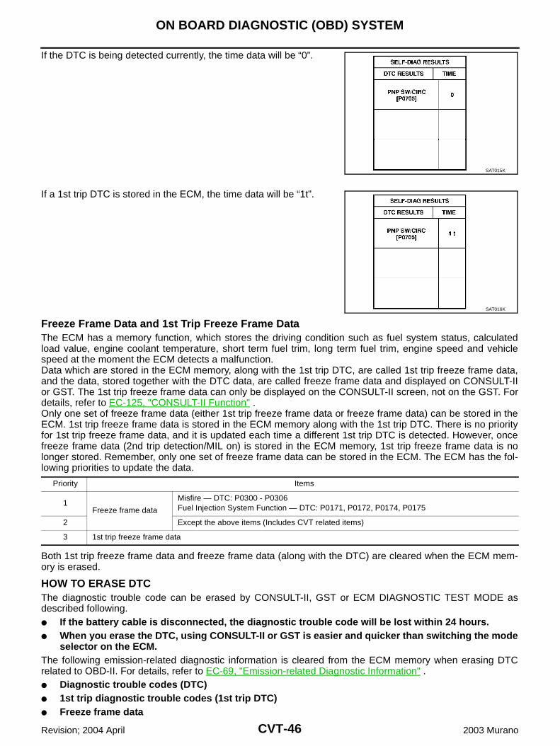
CVT-46
ON BOARD DIAGNOSTIC (OBD) SYSTEM
Revision; 2004 April 2003 Murano
If the DTC is being detected currently, the time data will be “0”.
If a 1st trip DTC is stored in the ECM, the time data will be “1t”.
Freeze Frame Data and 1st Trip Freeze Frame DataThe ECM has a memory function, which stores the driving condition such as fuel system status, calculatedload value, engine coolant temperature, short term fuel trim, long term fuel trim, engine speed and vehiclespeed at the moment the ECM detects a malfunction.Data which are stored in the ECM memory, along with the 1st trip DTC, are called 1st trip freeze frame data,and the data, stored together with the DTC data, are called freeze frame data and displayed on CONSULT-IIor GST. The 1st trip freeze frame data can only be displayed on the CONSULT-II screen, not on the GST. Fordetails, refer to EC-125, "CONSULT-II Function" .Only one set of freeze frame data (either 1st trip freeze frame data or freeze frame data) can be stored in theECM. 1st trip freeze frame data is stored in the ECM memory along with the 1st trip DTC. There is no priorityfor 1st trip freeze frame data, and it is updated each time a different 1st trip DTC is detected. However, oncefreeze frame data (2nd trip detection/MIL on) is stored in the ECM memory, 1st trip freeze frame data is nolonger stored. Remember, only one set of freeze frame data can be stored in the ECM. The ECM has the fol-lowing priorities to update the data.
Both 1st trip freeze frame data and freeze frame data (along with the DTC) are cleared when the ECM mem-ory is erased.
HOW TO ERASE DTCThe diagnostic trouble code can be erased by CONSULT-II, GST or ECM DIAGNOSTIC TEST MODE asdescribed following. If the battery cable is disconnected, the diagnostic trouble code will be lost within 24 hours. When you erase the DTC, using CONSULT-II or GST is easier and quicker than switching the mode
selector on the ECM.The following emission-related diagnostic information is cleared from the ECM memory when erasing DTCrelated to OBD-II. For details, refer to EC-69, "Emission-related Diagnostic Information" . Diagnostic trouble codes (DTC) 1st trip diagnostic trouble codes (1st trip DTC) Freeze frame data
SAT015K
SAT016K
Priority Items
1Freeze frame data
Misfire — DTC: P0300 - P0306Fuel Injection System Function — DTC: P0171, P0172, P0174, P0175
2 Except the above items (Includes CVT related items)
3 1st trip freeze frame data
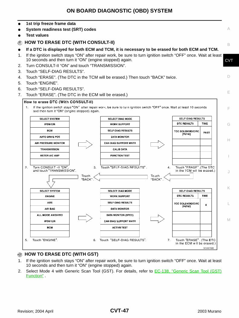
ON BOARD DIAGNOSTIC (OBD) SYSTEM
CVT-47
D
E
F
G
H
I
J
K
L
M
A
B
CVT
Revision; 2004 April 2003 Murano
1st trip freeze frame data System readiness test (SRT) codes Test values
HOW TO ERASE DTC (WITH CONSULT-II)
If a DTC is displayed for both ECM and TCM, it is necessary to be erased for both ECM and TCM.1. If the ignition switch stays “ON” after repair work, be sure to turn ignition switch “OFF” once. Wait at least
10 seconds and then turn it “ON” (engine stopped) again.2. Turn CONSULT-II “ON” and touch “TRANSMISSION”.3. Touch “SELF-DIAG RESULTS”.4. Touch “ERASE”. (The DTC in the TCM will be erased.) Then touch “BACK” twice.5. Touch “ENGINE”.6. Touch “SELF-DIAG RESULTS”.7. Touch “ERASE”. (The DTC in the ECM will be erased.)
HOW TO ERASE DTC (WITH GST)1. If the ignition switch stays “ON” after repair work, be sure to turn ignition switch “OFF” once. Wait at least
10 seconds and then turn it “ON” (engine stopped) again.2. Select Mode 4 with Generic Scan Tool (GST). For details, refer to EC-138, "Generic Scan Tool (GST)
Function" .
SCIA5768E
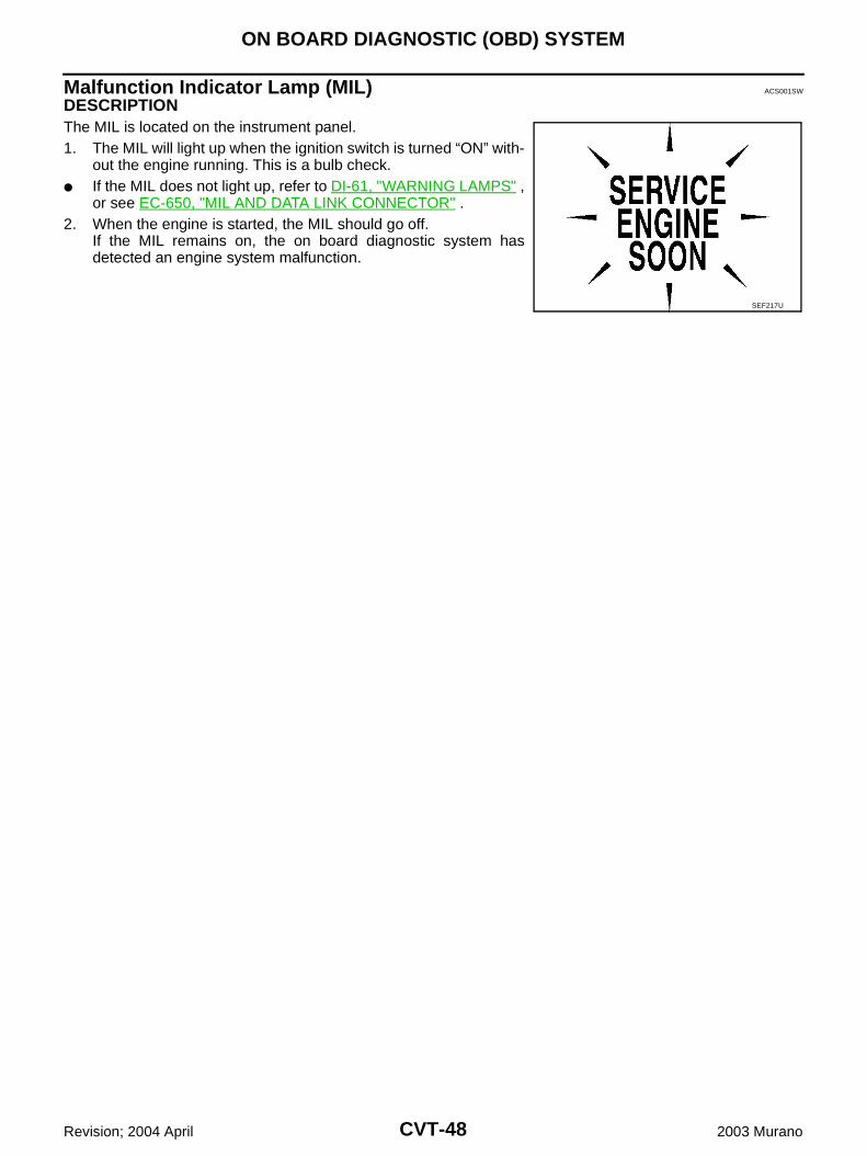
CVT-48
ON BOARD DIAGNOSTIC (OBD) SYSTEM
Revision; 2004 April 2003 Murano
Malfunction Indicator Lamp (MIL) ACS001SW
DESCRIPTION The MIL is located on the instrument panel.1. The MIL will light up when the ignition switch is turned “ON” with-
out the engine running. This is a bulb check. If the MIL does not light up, refer to DI-61, "WARNING LAMPS" ,
or see EC-650, "MIL AND DATA LINK CONNECTOR" .2. When the engine is started, the MIL should go off.
If the MIL remains on, the on board diagnostic system hasdetected an engine system malfunction.
SEF217U

TROUBLE DIAGNOSIS
CVT-49
D
E
F
G
H
I
J
K
L
M
A
B
CVT
Revision; 2004 April 2003 Murano
TROUBLE DIAGNOSIS PFP:00004
DTC Inspection Priority Chart ACS001SX
If some DTCs are displayed at the same time, perform inspections one by one based on the following prioritychart.NOTE:If DTC U1000 is displayed with other DTCs, first perform the trouble diagnosis for DTC U1000. Refer toCVT-76 .
Fail-Safe ACS001SY
The TCM has an electrical fail-safe mode. This mode makes it possible to operate even if there is an error in amain electronic control input/output signal circuit.
FAIL-SAFE FUNCTION If any malfunction occurs in a sensor or solenoid, this function controls the CVT to make driving possible.
Output Speed Sensor (Secondary Speed Sensor) The shift pattern is changed in accordance with throttle position when an unexpected signal is sent from
the output speed sensor (secondary speed sensor) to the TCM. The Second position is inhibited, and thetransmission is put in “D” if “S” is selected.
Input Speed Sensor (Primary Speed Sensor) The shift pattern is changed in accordance with throttle position and secondary speed (vehicle speed)
when an unexpected signal is sent from the input speed sensor (primary speed sensor) to the TCM. TheSecond position is inhibited and the transmission is put in “D” if “S” is selected.
PNP Switch If an unexpected signal is sent from the PNP switch to the TCM, the transmission is put in “D”
CVT Fluid Temperature Sensor If an unexpected signal is sent from the CVT fluid temperature sensor to the TCM, the gear ratio in use
before receiving the unexpected signal is maintained or the gear ratio is controlled to keep engine speedunder 5000 rpm.
Transmission Fluid Pressure Sensor A (Secondary Pressure Sensor) If an unexpected signal is sent from the transmission fluid pressure sensor A (secondary pressure sensor)
to the TCM, the secondary pressure feedback control is stopped and the offset value obtained before thenon-standard condition occurs is used to control line pressure.
If transmission fluid pressure sensor A (secondary pressure sensor) error signal is input to TCM, second-ary pressure feedback control stops, but line pressure is controlled normally.
Pressure Control Solenoid A (Line Pressure Solenoid) If an unexpected signal is sent from the solenoid to the TCM, the pressure control solenoid A (line pres-
sure solenoid) is turned “off” to achieve the maximum fluid pressure.
Pressure Control Solenoid B (Secondary Pressure Solenoid) If an unexpected signal is sent from the solenoid to the TCM, the pressure control solenoid B (secondary
pressure solenoid) is turned “off” to achieve the maximum fluid pressure.
Torque Converter Clutch Solenoid If an unexpected signal is sent from the solenoid to the TCM, the torque converter clutch solenoid is
turned “off” to cancel the lock-up.
Step Motor If an unexpected signal is sent from the step motor to the TCM, the step motor coil phases “A” through “D”
are all turned “off” to hold the gear ratio used right before the non-standard condition occurred.
Priority Detected items (DTC)
1 U1000 CAN communication line
2 Except above
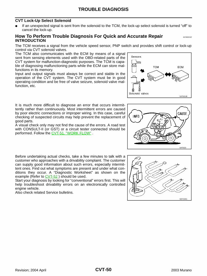
CVT-50
TROUBLE DIAGNOSIS
Revision; 2004 April 2003 Murano
CVT Lock-Up Select Solenoid If an unexpected signal is sent from the solenoid to the TCM, the lock-up select solenoid is turned “off” to
cancel the lock-up.
How To Perform Trouble Diagnosis For Quick and Accurate Repair ACS001SZ
INTRODUCTIONThe TCM receives a signal from the vehicle speed sensor, PNP switch and provides shift control or lock-upcontrol via CVT solenoid valves.The TCM also communicates with the ECM by means of a signalsent from sensing elements used with the OBD-related parts of theCVT system for malfunction-diagnostic purposes. The TCM is capa-ble of diagnosing malfunctioning parts while the ECM can store mal-functions in its memory.Input and output signals must always be correct and stable in theoperation of the CVT system. The CVT system must be in goodoperating condition and be free of valve seizure, solenoid valve mal-function, etc.
It is much more difficult to diagnose an error that occurs intermit-tently rather than continuously. Most intermittent errors are causedby poor electric connections or improper wiring. In this case, carefulchecking of suspected circuits may help prevent the replacement ofgood parts.A visual check only may not find the cause of the errors. A road testwith CONSULT-II (or GST) or a circuit tester connected should beperformed. Follow the CVT-51, "WORK FLOW" .
Before undertaking actual checks, take a few minutes to talk with acustomer who approaches with a drivability complaint. The customercan supply good information about such errors, especially intermit-tent ones. Find out what symptoms are present and under what con-ditions they occur. A “Diagnostic Worksheet” as shown on theexample (Refer to CVT-52 ) should be used.Start your diagnosis by looking for “conventional” errors first. This willhelp troubleshoot drivability errors on an electronically controlledengine vehicle.Also check related Service bulletins.
SAT631IB
SAT632I
SEF234G
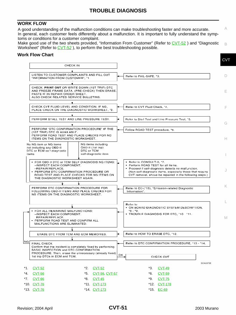
TROUBLE DIAGNOSIS
CVT-51
D
E
F
G
H
I
J
K
L
M
A
B
CVT
Revision; 2004 April 2003 Murano
WORK FLOWA good understanding of the malfunction conditions can make troubleshooting faster and more accurate.In general, each customer feels differently about a malfunction. It is important to fully understand the symp-toms or conditions for a customer complaint.Make good use of the two sheets provided, “Information From Customer” (Refer to CVT-52 ) and “DiagnosticWorksheet” (Refer to CVT-52 ), to perform the best troubleshooting possible.
Work Flow Chart
*1. CVT-52 *2. CVT-52 *3. CVT-49
*4. CVT-56 *5. CVT-56, CVT-57 *6. CVT-59
*7. CVT-66 *8. CVT-45 *9. CVT-75
*10. CVT-76 *11. CVT-173 *12. CVT-178
*13. CVT-76 *14. CVT-173 *15. EC-69
SCIA1973E
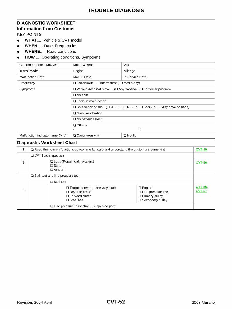
CVT-52
TROUBLE DIAGNOSIS
Revision; 2004 April 2003 Murano
DIAGNOSTIC WORKSHEETInformation from CustomerKEY POINTS WHAT..... Vehicle & CVT model WHEN..... Date, Frequencies WHERE..... Road conditions HOW..... Operating conditions, Symptoms
Diagnostic Worksheet Chart
Customer name MR/MS Model & Year VIN
Trans. Model Engine Mileage
malfunction Date Manuf. Date In Service Date
Frequency Continuous Intermittent ( times a day)
Symptoms Vehicle does not move. ( Any position Particular position)
No shift
Lock-up malfunction
Shift shock or slip ( N → D N → R Lock-up Any drive position)
Noise or vibration
No pattern select
Others( )
Malfunction indicator lamp (MIL) Continuously lit Not lit
1 Read the item on “cautions concerning fail-safe and understand the customer's complaint. CVT-49
2
CVT fluid inspection
CVT-56 Leak (Repair leak location.) State Amount
3
Stall test and line pressure test
CVT-56, CVT-57
Stall test
Torque converter one-way clutch Reverse brake Forward clutch Steel belt
Engine Line pressure low Primary pulley Secondary pulley
Line pressure inspection - Suspected part:
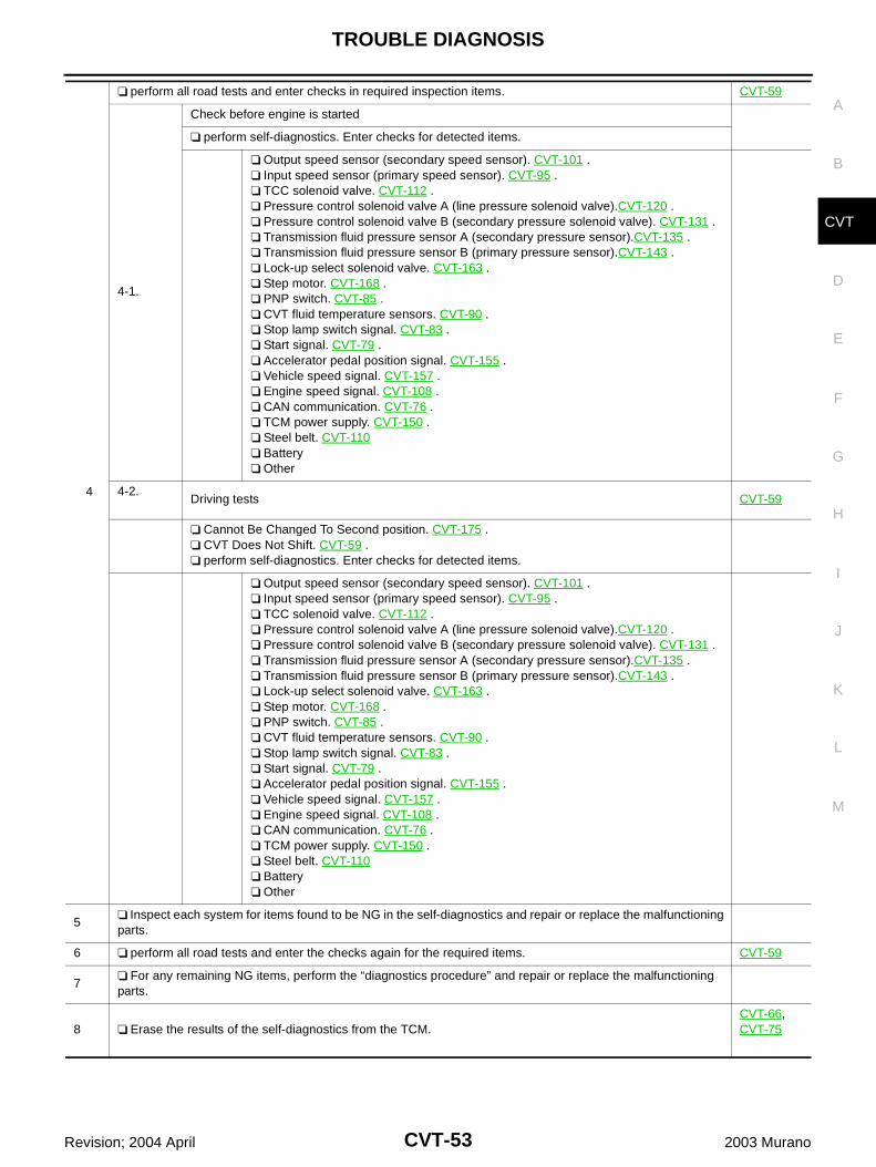
TROUBLE DIAGNOSIS
CVT-53
D
E
F
G
H
I
J
K
L
M
A
B
CVT
Revision; 2004 April 2003 Murano
4
perform all road tests and enter checks in required inspection items. CVT-59
4-1.
Check before engine is started
perform self-diagnostics. Enter checks for detected items.
Output speed sensor (secondary speed sensor). CVT-101 . Input speed sensor (primary speed sensor). CVT-95 . TCC solenoid valve. CVT-112 . Pressure control solenoid valve A (line pressure solenoid valve).CVT-120 . Pressure control solenoid valve B (secondary pressure solenoid valve). CVT-131 . Transmission fluid pressure sensor A (secondary pressure sensor).CVT-135 . Transmission fluid pressure sensor B (primary pressure sensor).CVT-143 . Lock-up select solenoid valve. CVT-163 . Step motor. CVT-168 . PNP switch. CVT-85 . CVT fluid temperature sensors. CVT-90 . Stop lamp switch signal. CVT-83 . Start signal. CVT-79 . Accelerator pedal position signal. CVT-155 . Vehicle speed signal. CVT-157 . Engine speed signal. CVT-108 . CAN communication. CVT-76 . TCM power supply. CVT-150 . Steel belt. CVT-110 Battery Other
4-2.Driving tests CVT-59
Cannot Be Changed To Second position. CVT-175 . CVT Does Not Shift. CVT-59 . perform self-diagnostics. Enter checks for detected items.
Output speed sensor (secondary speed sensor). CVT-101 . Input speed sensor (primary speed sensor). CVT-95 . TCC solenoid valve. CVT-112 . Pressure control solenoid valve A (line pressure solenoid valve).CVT-120 . Pressure control solenoid valve B (secondary pressure solenoid valve). CVT-131 . Transmission fluid pressure sensor A (secondary pressure sensor).CVT-135 . Transmission fluid pressure sensor B (primary pressure sensor).CVT-143 . Lock-up select solenoid valve. CVT-163 . Step motor. CVT-168 . PNP switch. CVT-85 . CVT fluid temperature sensors. CVT-90 . Stop lamp switch signal. CVT-83 . Start signal. CVT-79 . Accelerator pedal position signal. CVT-155 . Vehicle speed signal. CVT-157 . Engine speed signal. CVT-108 . CAN communication. CVT-76 . TCM power supply. CVT-150 . Steel belt. CVT-110 Battery Other
5 Inspect each system for items found to be NG in the self-diagnostics and repair or replace the malfunctioning parts.
6 perform all road tests and enter the checks again for the required items. CVT-59
7 For any remaining NG items, perform the “diagnostics procedure” and repair or replace the malfunctioning parts.
8 Erase the results of the self-diagnostics from the TCM.CVT-66, CVT-75
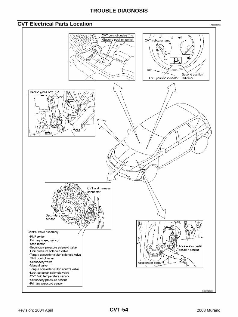
CVT-54
TROUBLE DIAGNOSIS
Revision; 2004 April 2003 Murano
CVT Electrical Parts Location ACS001T0
SCIA4282E
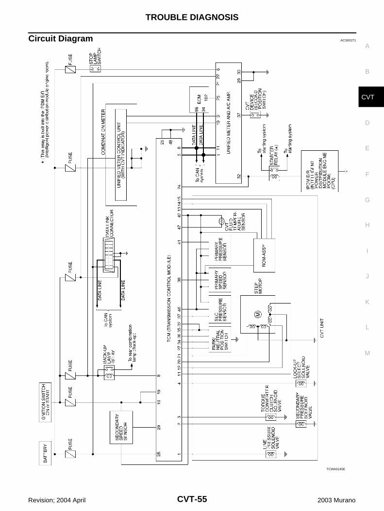
TROUBLE DIAGNOSIS
CVT-55
D
E
F
G
H
I
J
K
L
M
A
B
CVT
Revision; 2004 April 2003 Murano
Circuit Diagram ACS001T1
TCWA0145E
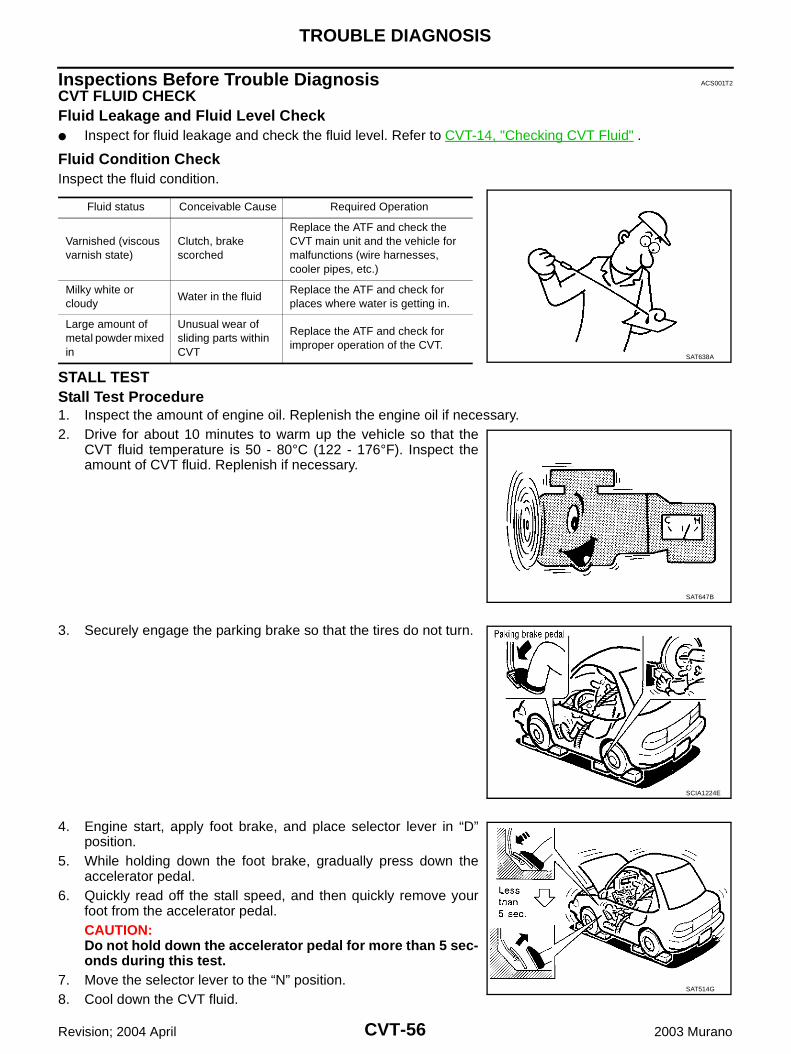
CVT-56
TROUBLE DIAGNOSIS
Revision; 2004 April 2003 Murano
Inspections Before Trouble Diagnosis ACS001T2
CVT FLUID CHECKFluid Leakage and Fluid Level Check Inspect for fluid leakage and check the fluid level. Refer to CVT-14, "Checking CVT Fluid" .
Fluid Condition CheckInspect the fluid condition.
STALL TESTStall Test Procedure1. Inspect the amount of engine oil. Replenish the engine oil if necessary.2. Drive for about 10 minutes to warm up the vehicle so that the
CVT fluid temperature is 50 - 80°C (122 - 176°F). Inspect theamount of CVT fluid. Replenish if necessary.
3. Securely engage the parking brake so that the tires do not turn.
4. Engine start, apply foot brake, and place selector lever in “D”position.
5. While holding down the foot brake, gradually press down theaccelerator pedal.
6. Quickly read off the stall speed, and then quickly remove yourfoot from the accelerator pedal.CAUTION:Do not hold down the accelerator pedal for more than 5 sec-onds during this test.
7. Move the selector lever to the “N” position.8. Cool down the CVT fluid.
Fluid status Conceivable Cause Required Operation
Varnished (viscous varnish state)
Clutch, brake scorched
Replace the ATF and check the CVT main unit and the vehicle for malfunctions (wire harnesses, cooler pipes, etc.)
Milky white or cloudy
Water in the fluidReplace the ATF and check for places where water is getting in.
Large amount of metal powder mixed in
Unusual wear of sliding parts within CVT
Replace the ATF and check for improper operation of the CVT.
SAT638A
SAT647B
SCIA1224E
SAT514G
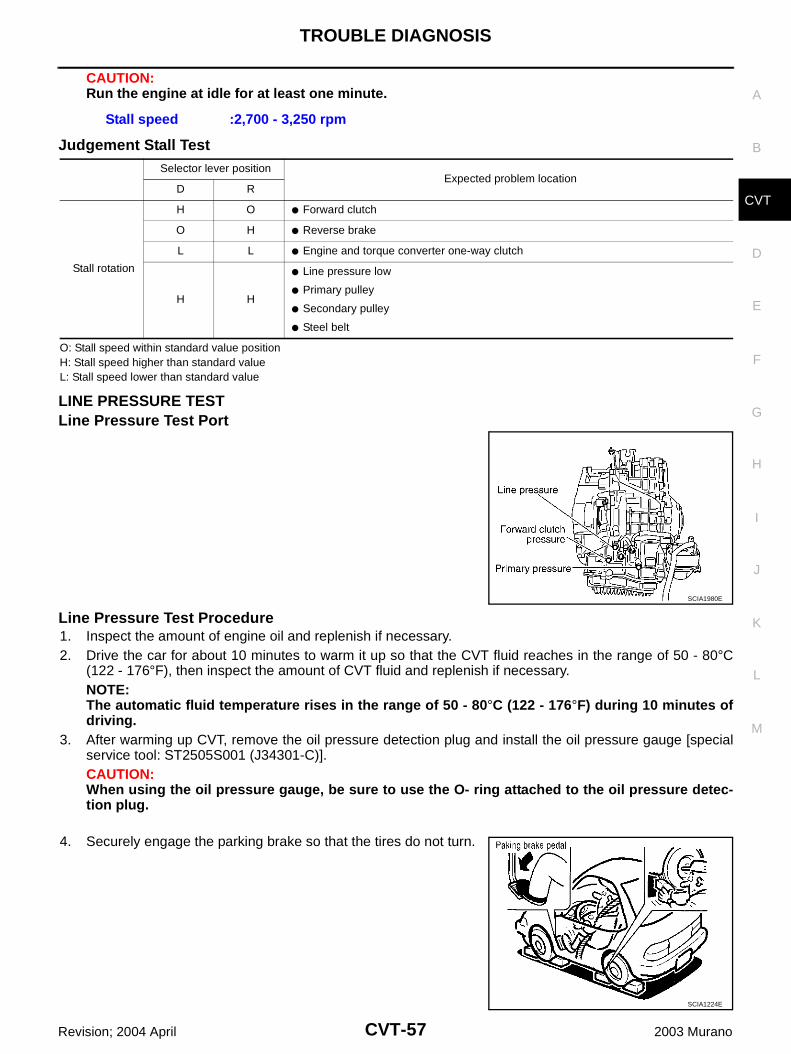
TROUBLE DIAGNOSIS
CVT-57
D
E
F
G
H
I
J
K
L
M
A
B
CVT
Revision; 2004 April 2003 Murano
CAUTION:Run the engine at idle for at least one minute.
Judgement Stall Test
O: Stall speed within standard value positionH: Stall speed higher than standard valueL: Stall speed lower than standard value
LINE PRESSURE TESTLine Pressure Test Port
Line Pressure Test Procedure1. Inspect the amount of engine oil and replenish if necessary.2. Drive the car for about 10 minutes to warm it up so that the CVT fluid reaches in the range of 50 - 80°C
(122 - 176°F), then inspect the amount of CVT fluid and replenish if necessary.NOTE:The automatic fluid temperature rises in the range of 50 - 80°C (122 - 176°F) during 10 minutes ofdriving.
3. After warming up CVT, remove the oil pressure detection plug and install the oil pressure gauge [specialservice tool: ST2505S001 (J34301-C)].CAUTION:When using the oil pressure gauge, be sure to use the O- ring attached to the oil pressure detec-tion plug.
4. Securely engage the parking brake so that the tires do not turn.
Stall speed :2,700 - 3,250 rpm
Selector lever positionExpected problem location
D R
Stall rotation
H O Forward clutch
O H Reverse brake
L L Engine and torque converter one-way clutch
H H
Line pressure low
Primary pulley
Secondary pulley
Steel belt
SCIA1980E
SCIA1224E
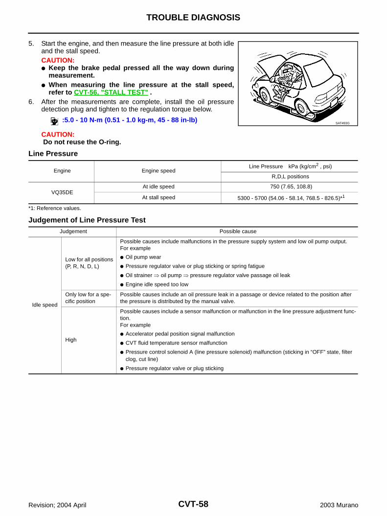
CVT-58
TROUBLE DIAGNOSIS
Revision; 2004 April 2003 Murano
5. Start the engine, and then measure the line pressure at both idleand the stall speed.CAUTION: Keep the brake pedal pressed all the way down during
measurement. When measuring the line pressure at the stall speed,
refer to CVT-56, "STALL TEST" . 6. After the measurements are complete, install the oil pressure
detection plug and tighten to the regulation torque below.
CAUTION: Do not reuse the O-ring.
Line Pressure
*1: Reference values.
Judgement of Line Pressure Test
:5.0 - 10 N-m (0.51 - 1.0 kg-m, 45 - 88 in-lb)SAT493G
Engine Engine speedLine Pressure kPa (kg/cm2 , psi)
R,D,L positions
VQ35DEAt idle speed 750 (7.65, 108.8)
At stall speed 5300 - 5700 (54.06 - 58.14, 768.5 - 826.5)*1
Judgement Possible cause
Idle speed
Low for all positions (P, R, N, D, L)
Possible causes include malfunctions in the pressure supply system and low oil pump output.For example
Oil pump wear
Pressure regulator valve or plug sticking or spring fatigue
Oil strainer oil pump pressure regulator valve passage oil leak
Engine idle speed too low
Only low for a spe-cific position
Possible causes include an oil pressure leak in a passage or device related to the position after the pressure is distributed by the manual valve.
High
Possible causes include a sensor malfunction or malfunction in the line pressure adjustment func-tion.For example
Accelerator pedal position signal malfunction
CVT fluid temperature sensor malfunction
Pressure control solenoid A (line pressure solenoid) malfunction (sticking in “OFF” state, filter clog, cut line)
Pressure regulator valve or plug sticking
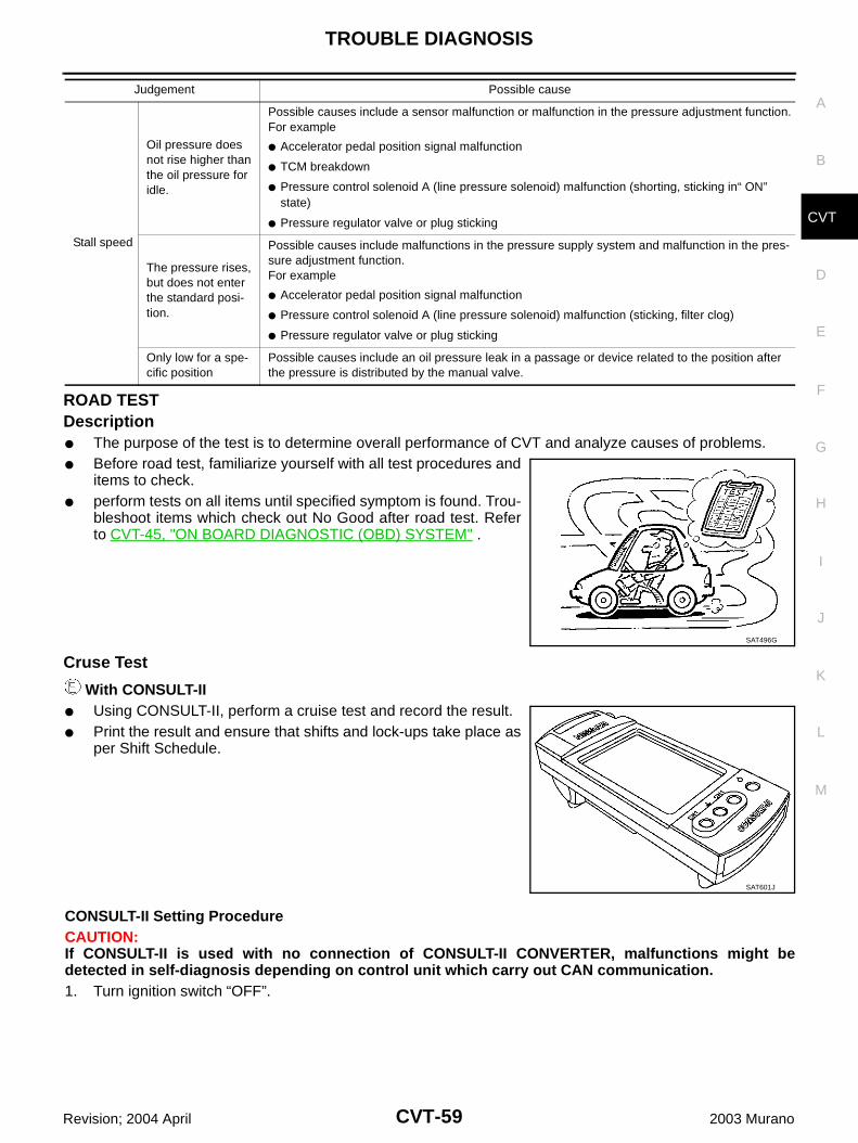
TROUBLE DIAGNOSIS
CVT-59
D
E
F
G
H
I
J
K
L
M
A
B
CVT
Revision; 2004 April 2003 Murano
ROAD TESTDescription The purpose of the test is to determine overall performance of CVT and analyze causes of problems. Before road test, familiarize yourself with all test procedures and
items to check. perform tests on all items until specified symptom is found. Trou-
bleshoot items which check out No Good after road test. Referto CVT-45, "ON BOARD DIAGNOSTIC (OBD) SYSTEM" .
Cruse Test
With CONSULT-II Using CONSULT-II, perform a cruise test and record the result. Print the result and ensure that shifts and lock-ups take place as
per Shift Schedule.
CONSULT-II Setting ProcedureCAUTION:If CONSULT-II is used with no connection of CONSULT-II CONVERTER, malfunctions might bedetected in self-diagnosis depending on control unit which carry out CAN communication.1. Turn ignition switch “OFF”.
Stall speed
Oil pressure does not rise higher than the oil pressure for idle.
Possible causes include a sensor malfunction or malfunction in the pressure adjustment function.For example
Accelerator pedal position signal malfunction
TCM breakdown
Pressure control solenoid A (line pressure solenoid) malfunction (shorting, sticking in“ ON” state)
Pressure regulator valve or plug sticking
The pressure rises, but does not enter the standard posi-tion.
Possible causes include malfunctions in the pressure supply system and malfunction in the pres-sure adjustment function.For example
Accelerator pedal position signal malfunction
Pressure control solenoid A (line pressure solenoid) malfunction (sticking, filter clog)
Pressure regulator valve or plug sticking
Only low for a spe-cific position
Possible causes include an oil pressure leak in a passage or device related to the position after the pressure is distributed by the manual valve.
Judgement Possible cause
SAT496G
SAT601J
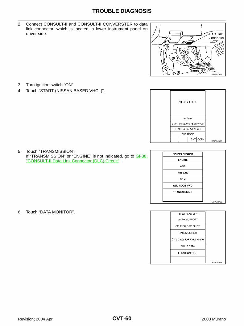
CVT-60
TROUBLE DIAGNOSIS
Revision; 2004 April 2003 Murano
2. Connect CONSULT-II and CONSULT-II CONVERSTER to datalink connector, which is located in lower instrument panel ondriver side.
3. Turn ignition switch “ON”.4. Touch “START (NISSAN BASED VHCL)”.
5. Touch “TRANSMISSION”.If “TRANSMISSION” or “ENGINE” is not indicated, go to GI-38,"CONSULT-II Data Link Connector (DLC) Circuit" .
6. Touch “DATA MONITOR”.
PBIB0196E
SAIA0450E
SCIA2272E
SCIA5492E
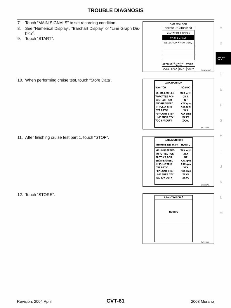
TROUBLE DIAGNOSIS
CVT-61
D
E
F
G
H
I
J
K
L
M
A
B
CVT
Revision; 2004 April 2003 Murano
7. Touch “MAIN SIGNALS” to set recording condition.8. See “Numerical Display”, “Barchart Display” or “Line Graph Dis-
play”.9. Touch “START”.
10. When performing cruise test, touch “Store Data”.
11. After finishing cruise test part 1, touch “STOP”.
12. Touch “STORE”.
SCIA5493E
SAT236K
SAT237K
SAT254K
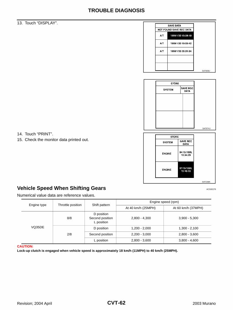
CVT-62
TROUBLE DIAGNOSIS
Revision; 2004 April 2003 Murano
13. Touch “DISPLAY”.
14. Touch “PRINT”.15. Check the monitor data printed out.
Vehicle Speed When Shifting Gears ACS001T8
Numerical value data are reference values.
CAUTION:Lock-up clutch is engaged when vehicle speed is approximately 18 km/h (11MPH) to 40 km/h (25MPH).
SAT608J
SAT974J
SAT238K
Engine type Throttle position Shift patternEngine speed (rpm)
At 40 km/h (25MPH) At 60 km/h (37MPH)
VQ35DE
8/8D position
Second positionL position
2,800 - 4,300 3,900 - 5,300
2/8
D position 1,200 - 2,000 1,300 - 2,100
Second position 2,200 - 3,000 2,800 - 3,600
L position 2,800 - 3,600 3,800 - 4,600
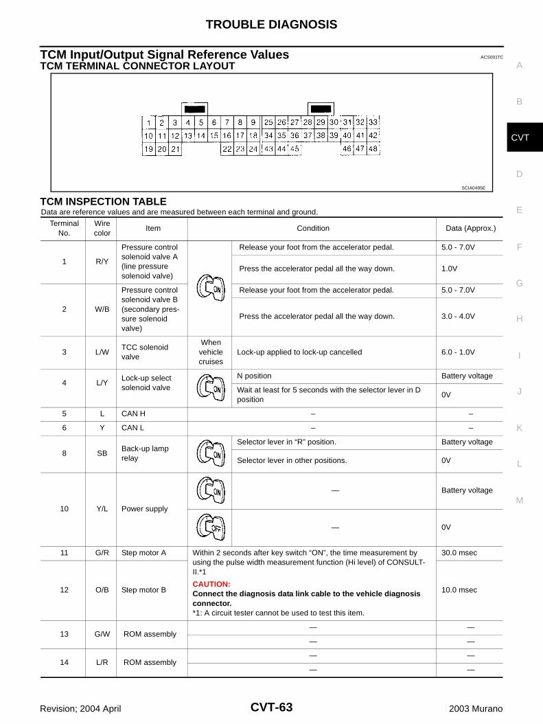
TROUBLE DIAGNOSIS
CVT-63
D
E
F
G
H
I
J
K
L
M
A
B
CVT
Revision; 2004 April 2003 Murano
TCM Input/Output Signal Reference Values ACS001TC
TCM TERMINAL CONNECTOR LAYOUT
TCM INSPECTION TABLEData are reference values and are measured between each terminal and ground.
SCIA0495E
Terminal No.
Wire color
Item Condition Data (Approx.)
1 R/Y
Pressure control solenoid valve A (line pressure solenoid valve)
Release your foot from the accelerator pedal. 5.0 - 7.0V
Press the accelerator pedal all the way down. 1.0V
2 W/B
Pressure control solenoid valve B (secondary pres-sure solenoid valve)
Release your foot from the accelerator pedal. 5.0 - 7.0V
Press the accelerator pedal all the way down. 3.0 - 4.0V
3 L/WTCC solenoid valve
When vehicle cruises
Lock-up applied to lock-up cancelled 6.0 - 1.0V
4 L/YLock-up select solenoid valve
N position Battery voltage
Wait at least for 5 seconds with the selector lever in D position
0V
5 L CAN H – –
6 Y CAN L – –
8 SBBack-up lamp relay
Selector lever in “R” position. Battery voltage
Selector lever in other positions. 0V
10 Y/L Power supply
— Battery voltage
— 0V
11 G/R Step motor A Within 2 seconds after key switch “ON”, the time measurement by using the pulse width measurement function (Hi level) of CONSULT-II.*1
CAUTION:Connect the diagnosis data link cable to the vehicle diagnosis connector.*1: A circuit tester cannot be used to test this item.
30.0 msec
12 O/B Step motor B 10.0 msec
13 G/W ROM assembly— —
— —
14 L/R ROM assembly— —
— —
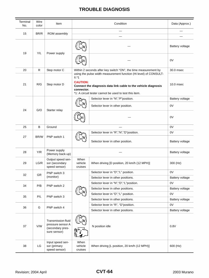
CVT-64
TROUBLE DIAGNOSIS
Revision; 2004 April 2003 Murano
15 BR/R ROM assembly— —
— —
19 Y/L Power supply
— Battery voltage
— 0V
20 R Step motor C Within 2 seconds after key switch “ON”, the time measurement by using the pulse width measurement function (Hi level) of CONSULT-II.*1
CAUTION:Connect the diagnosis data link cable to the vehicle diagnosis connector.*1: A circuit tester cannot be used to test this item.
30.0 msec
21 R/G Step motor D 10.0 msec
24 G/O Starter relay
Selector lever in “N”,“P”position. Battery voltage
Selector lever in other position. 0V
— 0V
25 B Ground — 0V
27 BR/W PNP switch 1
Selector lever in “R”,“N”,“D”position. 0V
Selector lever in other position. Battery voltage
28 Y/RPower supply(Memory back-up)
— Battery voltage
29 LG/ROutput speed sen-sor (secondary speed sensor)
When vehicle cruises
When driving [D position, 20 km/h (12 MPH)] 300 (Hz)
32 GRPNP switch 3 (monitor)
Selector lever in “D”,“L” position. 0V
Selector lever in other positions. Battery voltage
34 P/B PNP switch 2Selector lever in “N”,“D”,“L”position. 0V
Selector lever in other positions. Battery voltage
35 P/L PNP switch 3Selector lever in “D”,“L” position. 0V
Selector lever in other positions. Battery voltage
36 G PNP switch 4Selector lever in “R”, “D”position. 0V
Selector lever in other positions. Battery voltage
37 V/W
Transmission fluid pressure sensor A (secondary pres-sure sensor)
N position idle 0.8V
38 LGInput speed sen-sor (primary speed sensor)
When vehicle cruises
When driving [L position, 20 km/h (12 MPH)] 600 (Hz)
Terminal No.
Wire color
Item Condition Data (Approx.)

TROUBLE DIAGNOSIS
CVT-65
D
E
F
G
H
I
J
K
L
M
A
B
CVT
Revision; 2004 April 2003 Murano
41 V/O
Transmission fluid pressure sensor B (primary pressure sensor)
N position idle 0.7 - 1.2V
42 W/R Sensor ground — 0V
46 L/O Sensor power— 4.5 - 5.5V
47 VCVT fluid temper-ature sensor
When CVT fluid temperature is 20°C (68°F) 2.0V
When CVT fluid temperature is 80°C (176°F) 1.0V
48 B Ground — 0V
Terminal No.
Wire color
Item Condition Data (Approx.)
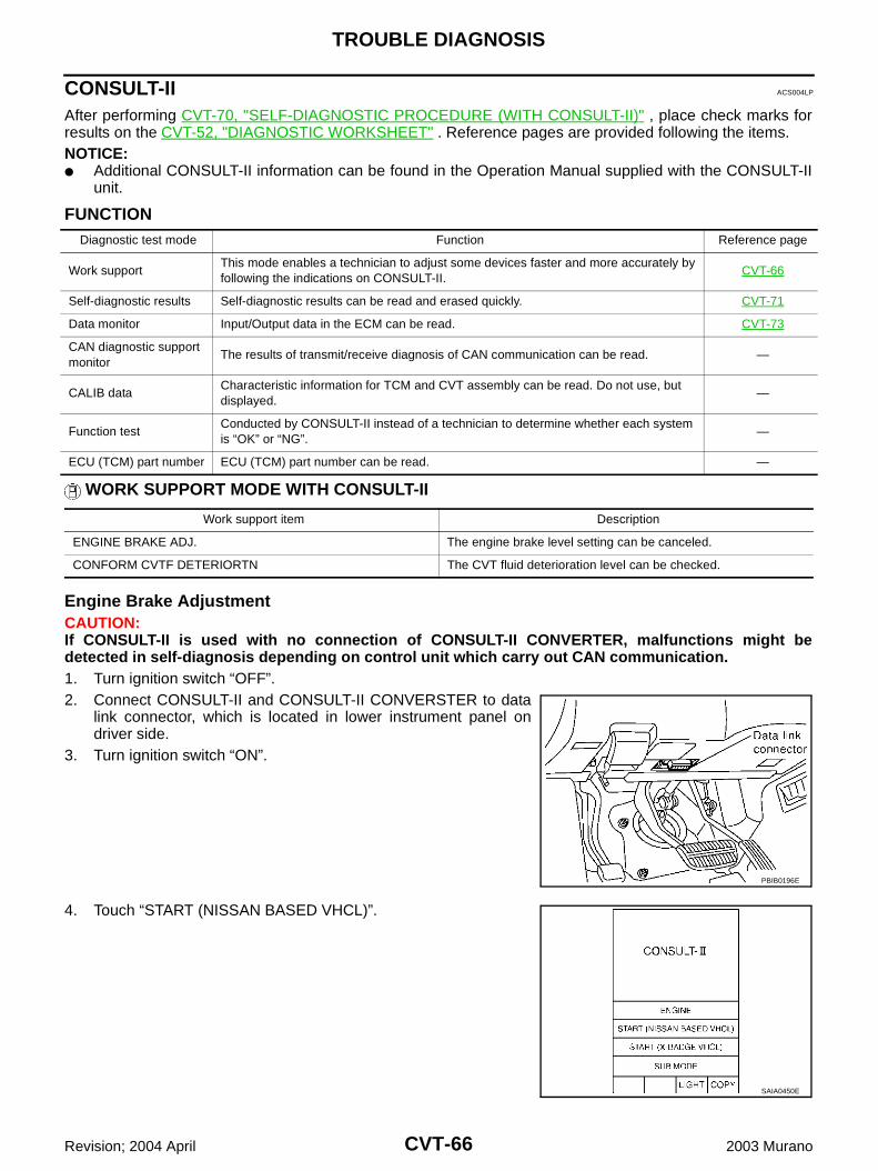
CVT-66
TROUBLE DIAGNOSIS
Revision; 2004 April 2003 Murano
CONSULT-II ACS004LP
After performing CVT-70, "SELF-DIAGNOSTIC PROCEDURE (WITH CONSULT-II)" , place check marks forresults on the CVT-52, "DIAGNOSTIC WORKSHEET" . Reference pages are provided following the items.NOTICE: Additional CONSULT-II information can be found in the Operation Manual supplied with the CONSULT-II
unit.
FUNCTION
WORK SUPPORT MODE WITH CONSULT-II
Engine Brake AdjustmentCAUTION:If CONSULT-II is used with no connection of CONSULT-II CONVERTER, malfunctions might bedetected in self-diagnosis depending on control unit which carry out CAN communication.1. Turn ignition switch “OFF”.2. Connect CONSULT-II and CONSULT-II CONVERSTER to data
link connector, which is located in lower instrument panel ondriver side.
3. Turn ignition switch “ON”.
4. Touch “START (NISSAN BASED VHCL)”.
Diagnostic test mode Function Reference page
Work supportThis mode enables a technician to adjust some devices faster and more accurately by following the indications on CONSULT-II.
CVT-66
Self-diagnostic results Self-diagnostic results can be read and erased quickly. CVT-71
Data monitor Input/Output data in the ECM can be read. CVT-73
CAN diagnostic support monitor
The results of transmit/receive diagnosis of CAN communication can be read. —
CALIB dataCharacteristic information for TCM and CVT assembly can be read. Do not use, but displayed.
—
Function testConducted by CONSULT-II instead of a technician to determine whether each system is “OK” or “NG”.
—
ECU (TCM) part number ECU (TCM) part number can be read. —
Work support item Description
ENGINE BRAKE ADJ. The engine brake level setting can be canceled.
CONFORM CVTF DETERIORTN The CVT fluid deterioration level can be checked.
PBIB0196E
SAIA0450E

TROUBLE DIAGNOSIS
CVT-67
D
E
F
G
H
I
J
K
L
M
A
B
CVT
Revision; 2004 April 2003 Murano
5. Touch “TRANSMISSION”.
6. Touch “WORK SUPPORT”.
7. Touch “ENGINE BRAKE ADJUSTMENT”.
8. Touch “START”.
9. Set “ENGINE BRAKE LEVEL” by touching “UP” or “DOWN”.
10. Turn ignition switch “OFF”, wait at least 5 seconds and then turnignition switch “ON”.
SCIA2272E
SCIA5492E
SCIA4287E
SCIA4288E
ENGINE BRAKE LEVEL0: Initial set value (Engine brake level control is activated)
OFF: Engine brake level control is deactivated.
SAT934J
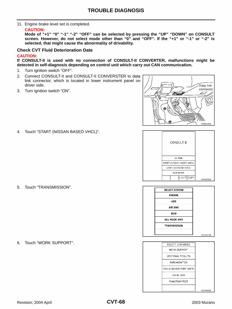
CVT-68
TROUBLE DIAGNOSIS
Revision; 2004 April 2003 Murano
11. Engine brake level set is completed.CAUTION:Mode of “+1” “0” “-1” “-2” “OFF” can be selected by pressing the “UP” “DOWN” on CONSULTscreen. However, do not select mode other than “0” and “OFF”. If the “+1” or “-1” or “-2” isselected, that might cause the abnormality of drivability.
Check CVT Fluid Deterioration DateCAUTION:If CONSULT-II is used with no connection of CONSULT-II CONVERTER, malfunctions might bedetected in self-diagnosis depending on control unit which carry out CAN communication.1. Turn ignition switch “OFF”.2. Connect CONSULT-II and CONSULT-II CONVERSTER to data
link connector, which is located in lower instrument panel ondriver side.
3. Turn ignition switch “ON”.
4. Touch “START (NISSAN BASED VHCL)”.
5. Touch “TRANSMISSION”.
6. Touch “WORK SUPPORT”.
PBIB0196E
SAIA0450E
SCIA2272E
SCIA5492E
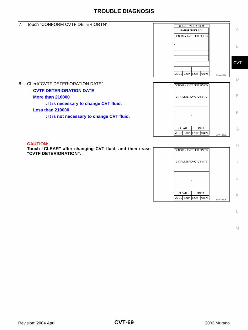
TROUBLE DIAGNOSIS
CVT-69
D
E
F
G
H
I
J
K
L
M
A
B
CVT
Revision; 2004 April 2003 Murano
7. Touch “CONFORM CVTF DETERIORTN”.
8. Check“CVTF DETERIORATION DATE”
CAUTION:Touch “CLEAR” after changing CVT fluid, and then erase“CVTF DETERIORATION”.
SCIA4287E
CVTF DETERIORATION DATEMore than 210000
: It is necessary to change CVT fluid.Less than 210000
: It is not necessary to change CVT fluid.
SCIA4289E
SCIA4290E
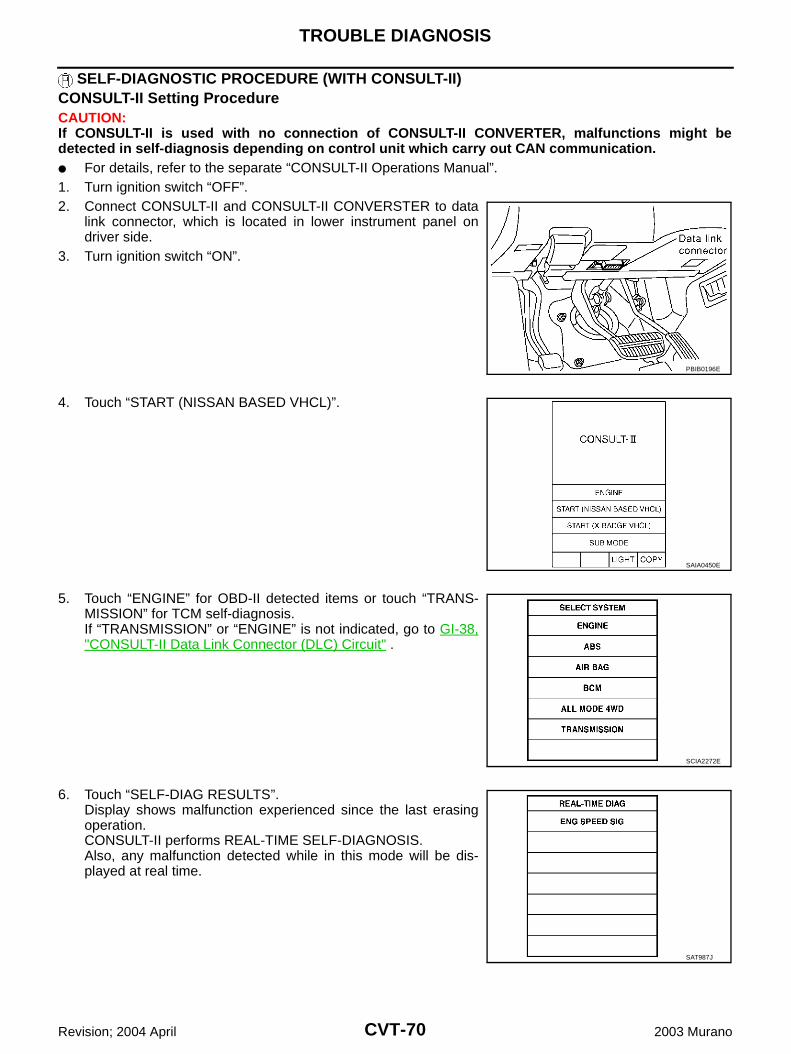
CVT-70
TROUBLE DIAGNOSIS
Revision; 2004 April 2003 Murano
SELF-DIAGNOSTIC PROCEDURE (WITH CONSULT-II)CONSULT-II Setting Procedure CAUTION:If CONSULT-II is used with no connection of CONSULT-II CONVERTER, malfunctions might bedetected in self-diagnosis depending on control unit which carry out CAN communication. For details, refer to the separate “CONSULT-II Operations Manual”.1. Turn ignition switch “OFF”.2. Connect CONSULT-II and CONSULT-II CONVERSTER to data
link connector, which is located in lower instrument panel ondriver side.
3. Turn ignition switch “ON”.
4. Touch “START (NISSAN BASED VHCL)”.
5. Touch “ENGINE” for OBD-II detected items or touch “TRANS-MISSION” for TCM self-diagnosis.If “TRANSMISSION” or “ENGINE” is not indicated, go to GI-38,"CONSULT-II Data Link Connector (DLC) Circuit" .
6. Touch “SELF-DIAG RESULTS”.Display shows malfunction experienced since the last erasingoperation.CONSULT-II performs REAL-TIME SELF-DIAGNOSIS.Also, any malfunction detected while in this mode will be dis-played at real time.
PBIB0196E
SAIA0450E
SCIA2272E
SAT987J
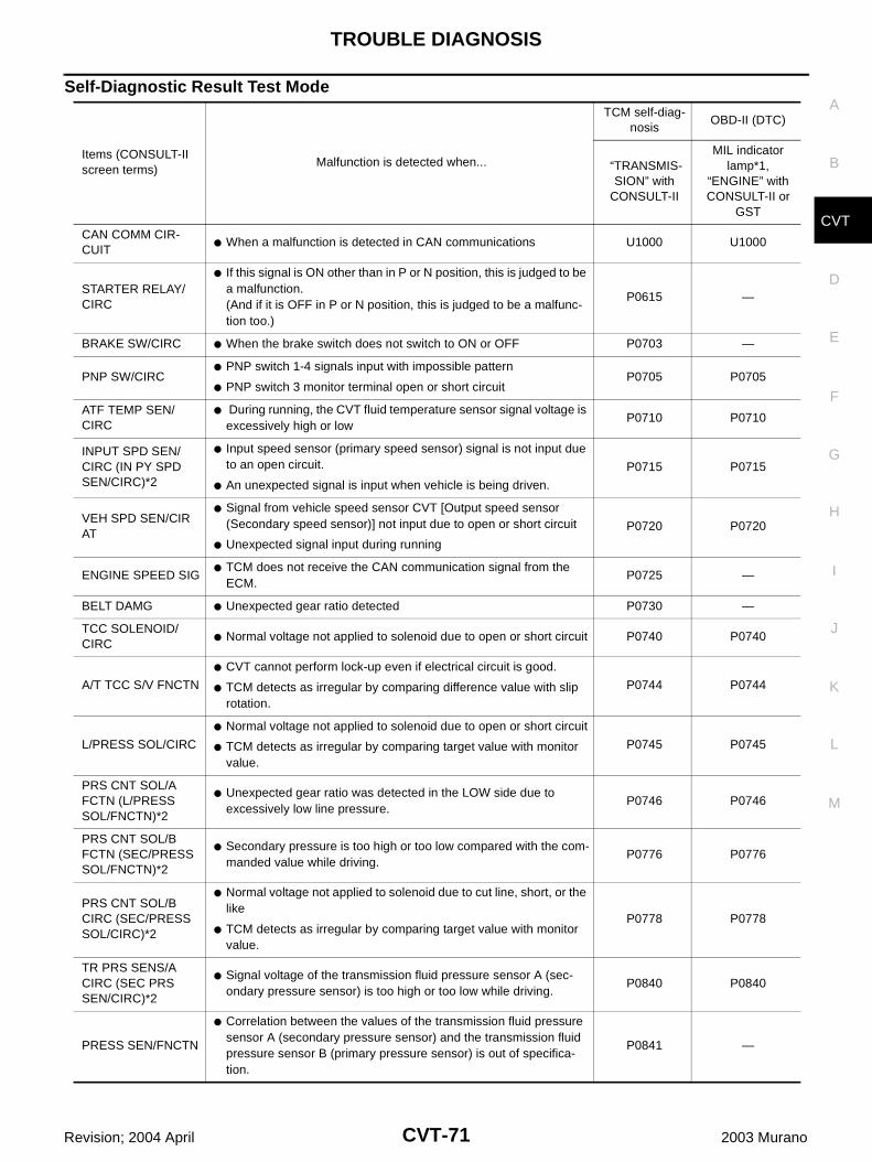
TROUBLE DIAGNOSIS
CVT-71
D
E
F
G
H
I
J
K
L
M
A
B
CVT
Revision; 2004 April 2003 Murano
Self-Diagnostic Result Test Mode
Items (CONSULT-II screen terms)
Malfunction is detected when...
TCM self-diag-nosis
OBD-II (DTC)
“TRANSMIS-SION” with
CONSULT-II
MIL indicator lamp*1,
“ENGINE” with CONSULT-II or
GST
CAN COMM CIR-CUIT
When a malfunction is detected in CAN communications U1000 U1000
STARTER RELAY/CIRC
If this signal is ON other than in P or N position, this is judged to be a malfunction.(And if it is OFF in P or N position, this is judged to be a malfunc-tion too.)
P0615 —
BRAKE SW/CIRC When the brake switch does not switch to ON or OFF P0703 —
PNP SW/CIRC PNP switch 1-4 signals input with impossible pattern
PNP switch 3 monitor terminal open or short circuitP0705 P0705
ATF TEMP SEN/CIRC
During running, the CVT fluid temperature sensor signal voltage is excessively high or low
P0710 P0710
INPUT SPD SEN/CIRC (IN PY SPD SEN/CIRC)*2
Input speed sensor (primary speed sensor) signal is not input due to an open circuit.
An unexpected signal is input when vehicle is being driven.
P0715 P0715
VEH SPD SEN/CIR AT
Signal from vehicle speed sensor CVT [Output speed sensor (Secondary speed sensor)] not input due to open or short circuit
Unexpected signal input during running
P0720 P0720
ENGINE SPEED SIG TCM does not receive the CAN communication signal from the
ECM.P0725 —
BELT DAMG Unexpected gear ratio detected P0730 —
TCC SOLENOID/CIRC
Normal voltage not applied to solenoid due to open or short circuit P0740 P0740
A/T TCC S/V FNCTN
CVT cannot perform lock-up even if electrical circuit is good.
TCM detects as irregular by comparing difference value with slip rotation.
P0744 P0744
L/PRESS SOL/CIRC
Normal voltage not applied to solenoid due to open or short circuit
TCM detects as irregular by comparing target value with monitor value.
P0745 P0745
PRS CNT SOL/A FCTN (L/PRESS SOL/FNCTN)*2
Unexpected gear ratio was detected in the LOW side due to excessively low line pressure.
P0746 P0746
PRS CNT SOL/B FCTN (SEC/PRESS SOL/FNCTN)*2
Secondary pressure is too high or too low compared with the com-manded value while driving.
P0776 P0776
PRS CNT SOL/B CIRC (SEC/PRESS SOL/CIRC)*2
Normal voltage not applied to solenoid due to cut line, short, or the like
TCM detects as irregular by comparing target value with monitor value.
P0778 P0778
TR PRS SENS/A CIRC (SEC PRS SEN/CIRC)*2
Signal voltage of the transmission fluid pressure sensor A (sec-ondary pressure sensor) is too high or too low while driving.
P0840 P0840
PRESS SEN/FNCTN
Correlation between the values of the transmission fluid pressure sensor A (secondary pressure sensor) and the transmission fluid pressure sensor B (primary pressure sensor) is out of specifica-tion.
P0841 —
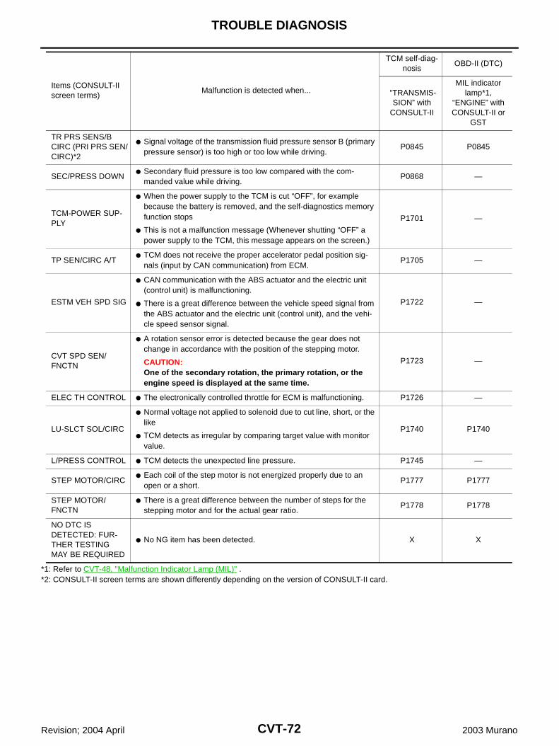
CVT-72
TROUBLE DIAGNOSIS
Revision; 2004 April 2003 Murano
*1: Refer to CVT-48, "Malfunction Indicator Lamp (MIL)" .*2: CONSULT-II screen terms are shown differently depending on the version of CONSULT-II card.
TR PRS SENS/B CIRC (PRI PRS SEN/CIRC)*2
Signal voltage of the transmission fluid pressure sensor B (primary pressure sensor) is too high or too low while driving.
P0845 P0845
SEC/PRESS DOWN Secondary fluid pressure is too low compared with the com-
manded value while driving.P0868 —
TCM-POWER SUP-PLY
When the power supply to the TCM is cut “OFF”, for example because the battery is removed, and the self-diagnostics memory function stops
This is not a malfunction message (Whenever shutting “OFF” a power supply to the TCM, this message appears on the screen.)
P1701 —
TP SEN/CIRC A/T TCM does not receive the proper accelerator pedal position sig-
nals (input by CAN communication) from ECM.P1705 —
ESTM VEH SPD SIG
CAN communication with the ABS actuator and the electric unit (control unit) is malfunctioning.
There is a great difference between the vehicle speed signal from the ABS actuator and the electric unit (control unit), and the vehi-cle speed sensor signal.
P1722 —
CVT SPD SEN/FNCTN
A rotation sensor error is detected because the gear does not change in accordance with the position of the stepping motor.
CAUTION:One of the secondary rotation, the primary rotation, or the engine speed is displayed at the same time.
P1723 —
ELEC TH CONTROL The electronically controlled throttle for ECM is malfunctioning. P1726 —
LU-SLCT SOL/CIRC
Normal voltage not applied to solenoid due to cut line, short, or the like
TCM detects as irregular by comparing target value with monitor value.
P1740 P1740
L/PRESS CONTROL TCM detects the unexpected line pressure. P1745 —
STEP MOTOR/CIRC Each coil of the step motor is not energized properly due to an
open or a short.P1777 P1777
STEP MOTOR/FNCTN
There is a great difference between the number of steps for the stepping motor and for the actual gear ratio.
P1778 P1778
NO DTC IS DETECTED: FUR-THER TESTING MAY BE REQUIRED
No NG item has been detected. X X
Items (CONSULT-II screen terms)
Malfunction is detected when...
TCM self-diag-nosis
OBD-II (DTC)
“TRANSMIS-SION” with
CONSULT-II
MIL indicator lamp*1,
“ENGINE” with CONSULT-II or
GST
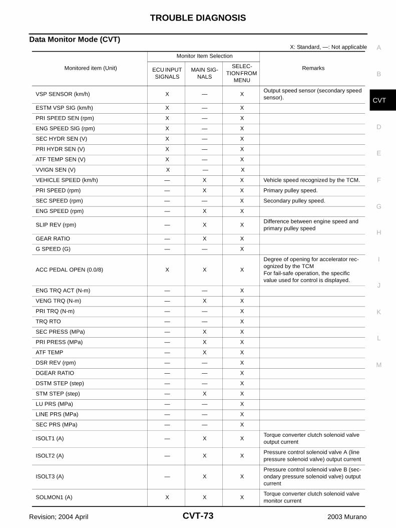
TROUBLE DIAGNOSIS
CVT-73
D
E
F
G
H
I
J
K
L
M
A
B
CVT
Revision; 2004 April 2003 Murano
Data Monitor Mode (CVT) X: Standard, —: Not applicable
Monitored item (Unit)
Monitor Item Selection
Remarks ECU INPUT SIGNALS
MAIN SIG-NALS
SELEC-TION FROM
MENU
VSP SENSOR (km/h) X — XOutput speed sensor (secondary speed sensor).
ESTM VSP SIG (km/h) X — X
PRI SPEED SEN (rpm) X — X
ENG SPEED SIG (rpm) X — X
SEC HYDR SEN (V) X — X
PRI HYDR SEN (V) X — X
ATF TEMP SEN (V) X — X
VVIGN SEN (V) X — X
VEHICLE SPEED (km/h) — X X Vehicle speed recognized by the TCM.
PRI SPEED (rpm) — X X Primary pulley speed.
SEC SPEED (rpm) — — X Secondary pulley speed.
ENG SPEED (rpm) — X X
SLIP REV (rpm) — X XDifference between engine speed and primary pulley speed
GEAR RATIO — X X
G SPEED (G) — — X
ACC PEDAL OPEN (0.0/8) X X X
Degree of opening for accelerator rec-ognized by the TCMFor fail-safe operation, the specific value used for control is displayed.
ENG TRQ ACT (N-m) — — X
VENG TRQ (N-m) — X X
PRI TRQ (N-m) — — X
TRQ RTO — — X
SEC PRESS (MPa) — X X
PRI PRESS (MPa) — X X
ATF TEMP — X X
DSR REV (rpm) — — X
DGEAR RATIO — — X
DSTM STEP (step) — — X
STM STEP (step) — X X
LU PRS (MPa) — — X
LINE PRS (MPa) — — X
SEC PRS (MPa) — — X
ISOLT1 (A) — X XTorque converter clutch solenoid valve output current
ISOLT2 (A) — X XPressure control solenoid valve A (line pressure solenoid valve) output current
ISOLT3 (A) — X XPressure control solenoid valve B (sec-ondary pressure solenoid valve) output current
SOLMON1 (A) X X XTorque converter clutch solenoid valve monitor current
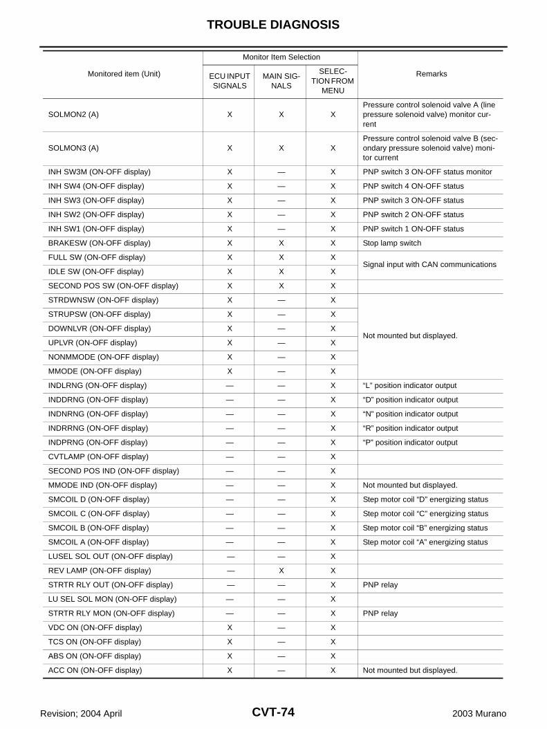
CVT-74
TROUBLE DIAGNOSIS
Revision; 2004 April 2003 Murano
SOLMON2 (A) X X XPressure control solenoid valve A (line pressure solenoid valve) monitor cur-rent
SOLMON3 (A) X X XPressure control solenoid valve B (sec-ondary pressure solenoid valve) moni-tor current
INH SW3M (ON-OFF display) X — X PNP switch 3 ON-OFF status monitor
INH SW4 (ON-OFF display) X — X PNP switch 4 ON-OFF status
INH SW3 (ON-OFF display) X — X PNP switch 3 ON-OFF status
INH SW2 (ON-OFF display) X — X PNP switch 2 ON-OFF status
INH SW1 (ON-OFF display) X — X PNP switch 1 ON-OFF status
BRAKESW (ON-OFF display) X X X Stop lamp switch
FULL SW (ON-OFF display) X X XSignal input with CAN communications
IDLE SW (ON-OFF display) X X X
SECOND POS SW (ON-OFF display) X X X
STRDWNSW (ON-OFF display) X — X
Not mounted but displayed.
STRUPSW (ON-OFF display) X — X
DOWNLVR (ON-OFF display) X — X
UPLVR (ON-OFF display) X — X
NONMMODE (ON-OFF display) X — X
MMODE (ON-OFF display) X — X
INDLRNG (ON-OFF display) — — X “L” position indicator output
INDDRNG (ON-OFF display) — — X “D” position indicator output
INDNRNG (ON-OFF display) — — X “N” position indicator output
INDRRNG (ON-OFF display) — — X “R” position indicator output
INDPRNG (ON-OFF display) — — X “P” position indicator output
CVTLAMP (ON-OFF display) — — X
SECOND POS IND (ON-OFF display) — — X
MMODE IND (ON-OFF display) — — X Not mounted but displayed.
SMCOIL D (ON-OFF display) — — X Step motor coil “D” energizing status
SMCOIL C (ON-OFF display) — — X Step motor coil “C” energizing status
SMCOIL B (ON-OFF display) — — X Step motor coil “B” energizing status
SMCOIL A (ON-OFF display) — — X Step motor coil “A” energizing status
LUSEL SOL OUT (ON-OFF display) — — X
REV LAMP (ON-OFF display) — X X
STRTR RLY OUT (ON-OFF display) — — X PNP relay
LU SEL SOL MON (ON-OFF display) — — X
STRTR RLY MON (ON-OFF display) — — X PNP relay
VDC ON (ON-OFF display) X — X
TCS ON (ON-OFF display) X — X
ABS ON (ON-OFF display) X — X
ACC ON (ON-OFF display) X — X Not mounted but displayed.
Monitored item (Unit)
Monitor Item Selection
Remarks ECU INPUT SIGNALS
MAIN SIG-NALS
SELEC-TION FROM
MENU
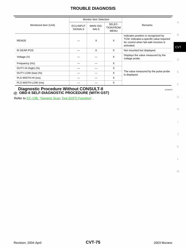
TROUBLE DIAGNOSIS
CVT-75
D
E
F
G
H
I
J
K
L
M
A
B
CVT
Revision; 2004 April 2003 Murano
Diagnostic Procedure Without CONSULT-II ACS001TE
OBD-II SELF-DIAGNOSTIC PROCEDURE (WITH GST)
Refer to EC-138, "Generic Scan Tool (GST) Function" .
RENGE — X X
Indicates position is recognized by TCM. Indicates a specific value required for control when fail-safe function is activated.
M GEAR POS — X X Not mounted but displayed.
Voltage (V) — — XDisplays the value measured by the voltage probe.
Frequency (Hz) — — X
The value measured by the pulse probe is displayed.
DUTY·HI (high) (%) — — X
DUTY·LOW (low) (%) — — X
PLS WIDTH·HI (ms) — — X
PLS WIDTH·LOW (ms) — — X
Monitored item (Unit)
Monitor Item Selection
Remarks ECU INPUT SIGNALS
MAIN SIG-NALS
SELEC-TION FROM
MENU
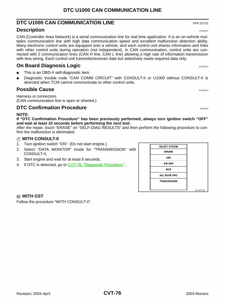
CVT-76
DTC U1000 CAN COMMUNICATION LINE
Revision; 2004 April 2003 Murano
DTC U1000 CAN COMMUNICATION LINE PFP:23710
Description ACS001TF
CAN (Controller Area Network) is a serial communication line for real time application. It is an on-vehicle mul-tiplex communication line with high data communication speed and excellent malfunction detection ability.Many electronic control units are equipped onto a vehicle, and each control unit shares information and linkswith other control units during operation (not independent). In CAN communication, control units are con-nected with 2 communication lines (CAN H line, CAN L line) allowing a high rate of information transmissionwith less wiring. Each control unit transmits/receives data but selectively reads required data only.
On Board Diagnosis Logic ACS001TG
This is an OBD-II self-diagnostic item. Diagnostic trouble code “CAN COMM CIRCUIT” with CONSULT-II or U1000 without CONSULT-II is
detected when TCM cannot communicate to other control units.
Possible Cause ACS001TH
Harness or connectors(CAN communication line is open or shorted.)
DTC Confirmation Procedure ACS001TI
NOTE:If “DTC Confirmation Procedure” has been previously performed, always turn ignition switch “OFF”and wait at least 10 seconds before performing the next test.After the repair, touch “ERASE” on “SELF-DIAG RESULTS” and then perform the following procedure to con-firm the malfunction is eliminated.
WITH CONSULT-II1. Turn ignition switch “ON”. (Do not start engine.)2. Select “DATA MONITOR” mode for “TRANSMISSION” with
CONSULT-II.3. Start engine and wait for at least 6 seconds.4. If DTC is detected, go to CVT-78, "Diagnostic Procedure" .
WITH GSTFollow the procedure “WITH CONSULT-II”.
SCIA2272E
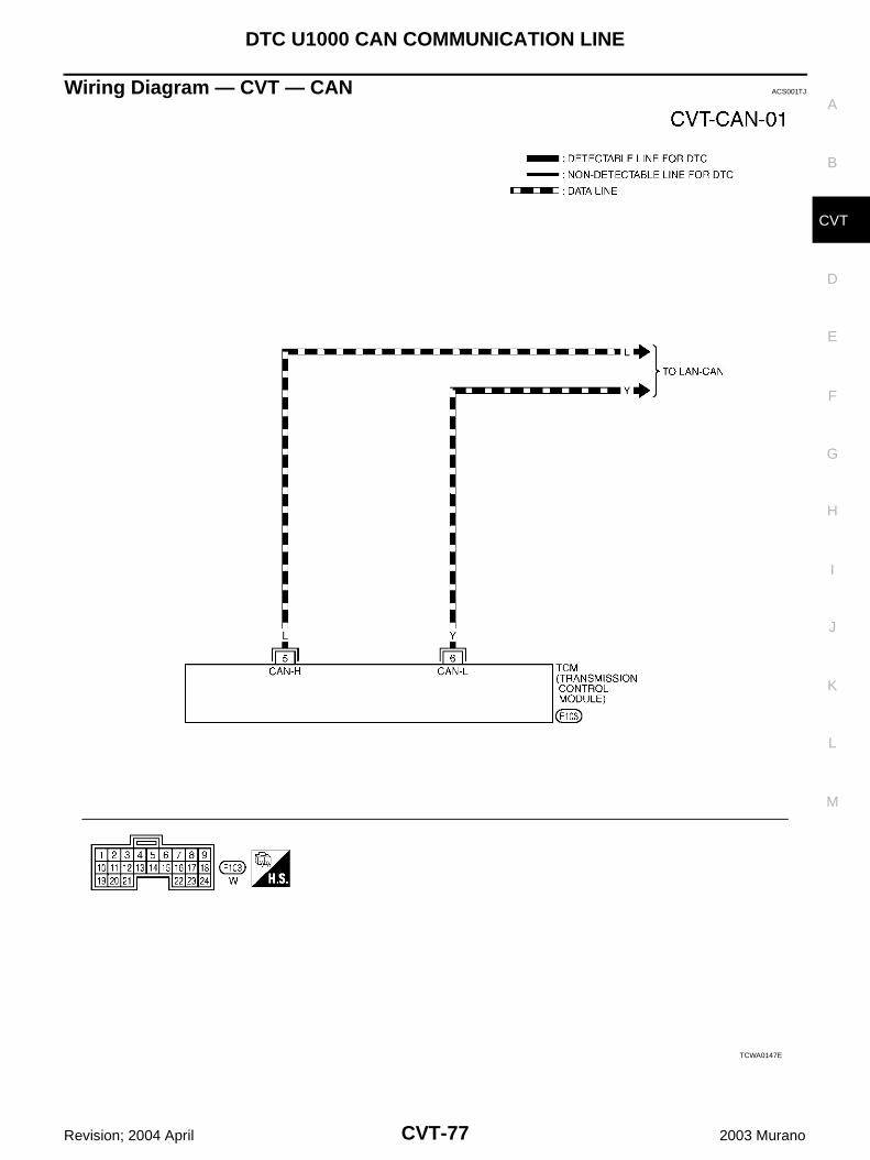
DTC U1000 CAN COMMUNICATION LINE
CVT-77
D
E
F
G
H
I
J
K
L
M
A
B
CVT
Revision; 2004 April 2003 Murano
Wiring Diagram — CVT — CAN ACS001TJ
TCWA0147E
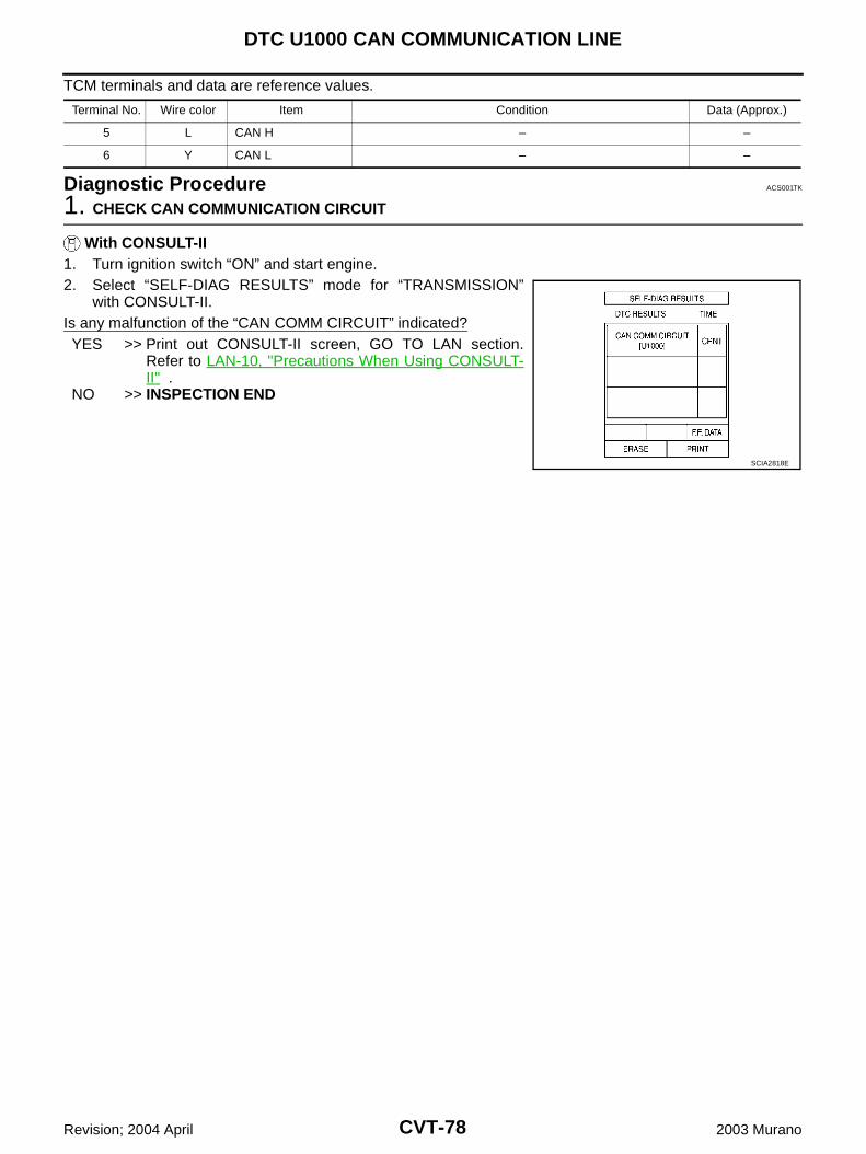
CVT-78
DTC U1000 CAN COMMUNICATION LINE
Revision; 2004 April 2003 Murano
TCM terminals and data are reference values.
Diagnostic Procedure ACS001TK
1. CHECK CAN COMMUNICATION CIRCUIT
With CONSULT-II1. Turn ignition switch “ON” and start engine.2. Select “SELF-DIAG RESULTS” mode for “TRANSMISSION”
with CONSULT-II.Is any malfunction of the “CAN COMM CIRCUIT” indicated?YES >> Print out CONSULT-II screen, GO TO LAN section.
Refer to LAN-10, "Precautions When Using CONSULT-II" .
NO >> INSPECTION END
Terminal No. Wire color Item Condition Data (Approx.)
5 L CAN H – –
6 Y CAN L – –
SCIA2818E
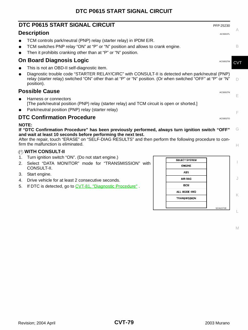
DTC P0615 START SIGNAL CIRCUIT
CVT-79
D
E
F
G
H
I
J
K
L
M
A
B
CVT
Revision; 2004 April 2003 Murano
DTC P0615 START SIGNAL CIRCUIT PFP:25230
Description ACS001TL
TCM controls park/neutral (PNP) relay (starter relay) in IPDM E/R. TCM switches PNP relay “ON” at “P” or “N” position and allows to crank engine. Then it prohibits cranking other than at “P” or “N” position.
On Board Diagnosis Logic ACS001TM
This is not an OBD-II self-diagnostic item. Diagnostic trouble code “STARTER RELAY/CIRC” with CONSULT-II is detected when park/neutral (PNP)
relay (starter relay) switched “ON” other than at “P” or “N” position. (Or when switched “OFF” at “P” or “N”position).
Possible Cause ACS001TN
Harness or connectors[The park/neutral position (PNP) relay (starter relay) and TCM circuit is open or shorted.]
Park/neutral position (PNP) relay (starter relay)
DTC Confirmation Procedure ACS001TO
NOTE:If “DTC Confirmation Procedure” has been previously performed, always turn ignition switch “OFF”and wait at least 10 seconds before performing the next test.After the repair, touch “ERASE” on “SELF-DIAG RESULTS” and then perform the following procedure to con-firm the malfunction is eliminated.
WITH CONSULT-II1. Turn ignition switch “ON”. (Do not start engine.)2. Select “DATA MONITOR” mode for “TRANSMISSION” with
CONSULT-II.3. Start engine.4. Drive vehicle for at least 2 consecutive seconds.5. If DTC is detected, go to CVT-81, "Diagnostic Procedure" .
SCIA2272E
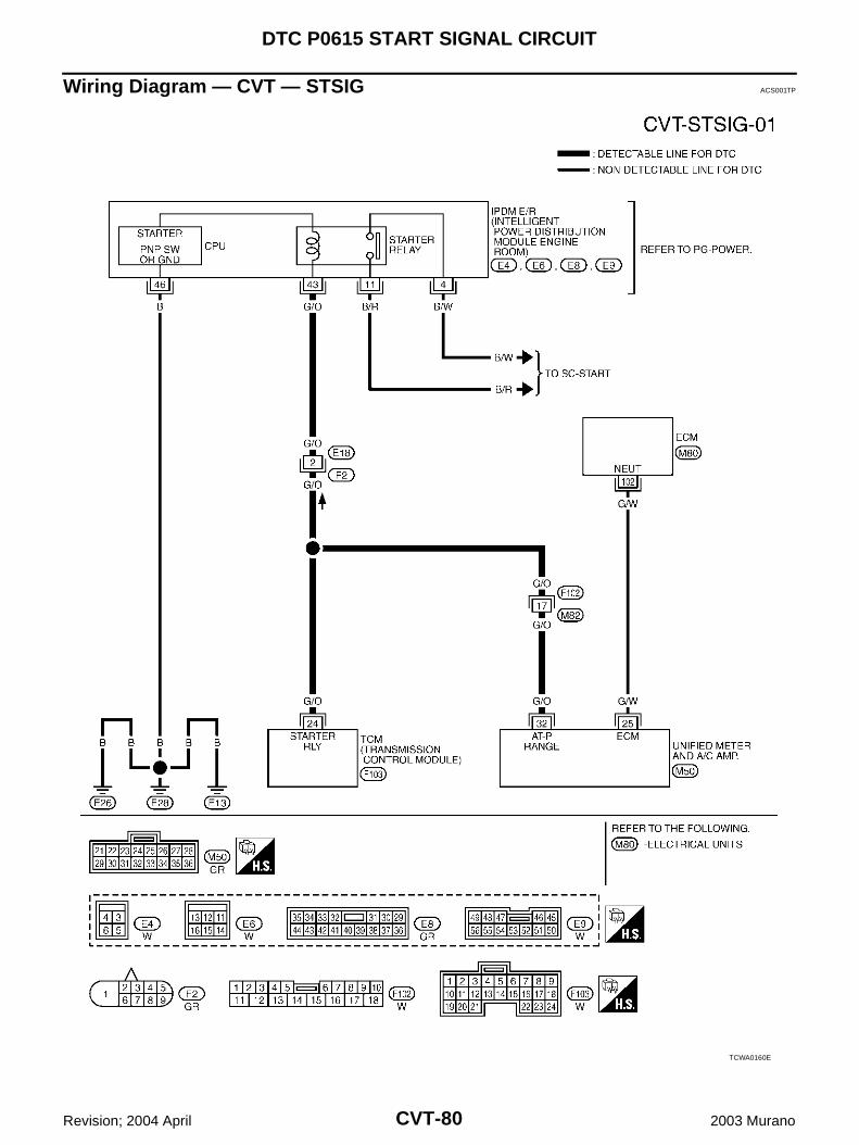
CVT-80
DTC P0615 START SIGNAL CIRCUIT
Revision; 2004 April 2003 Murano
Wiring Diagram — CVT — STSIG ACS001TP
TCWA0160E
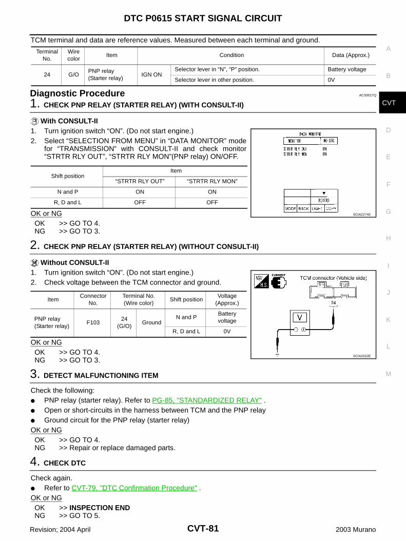
DTC P0615 START SIGNAL CIRCUIT
CVT-81
D
E
F
G
H
I
J
K
L
M
A
B
CVT
Revision; 2004 April 2003 Murano
TCM terminal and data are reference values. Measured between each terminal and ground.
Diagnostic Procedure ACS001TQ
1. CHECK PNP RELAY (STARTER RELAY) (WITH CONSULT-II)
With CONSULT-II1. Turn ignition switch “ON”. (Do not start engine.)2. Select “SELECTION FROM MENU” in “DATA MONITOR” mode
for “TRANSMISSION” with CONSULT-II and check monitor“STRTR RLY OUT”, “STRTR RLY MON”(PNP relay) ON/OFF.
OK or NGOK >> GO TO 4.NG >> GO TO 3.
2. CHECK PNP RELAY (STARTER RELAY) (WITHOUT CONSULT-II)
Without CONSULT-II1. Turn ignition switch “ON”. (Do not start engine.)2. Check voltage between the TCM connector and ground.
OK or NGOK >> GO TO 4.NG >> GO TO 3.
3. DETECT MALFUNCTIONING ITEM
Check the following: PNP relay (starter relay). Refer to PG-85, "STANDARDIZED RELAY" . Open or short-circuits in the harness between TCM and the PNP relay Ground circuit for the PNP relay (starter relay)OK or NGOK >> GO TO 4.NG >> Repair or replace damaged parts.
4. CHECK DTC
Check again. Refer to CVT-79, "DTC Confirmation Procedure" .OK or NGOK >> INSPECTION ENDNG >> GO TO 5.
Terminal No.
Wire color
Item Condition Data (Approx.)
24 G/OPNP relay(Starter relay)
IGN ONSelector lever in “N”, “P” position. Battery voltage
Selector lever in other position. 0V
Shift positionItem
“STRTR RLY OUT” “STRTR RLY MON”
N and P ON ON
R, D and L OFF OFF
SCIA2274E
ItemConnector
No.Terminal No.(Wire color)
Shift positionVoltage
(Approx.)
PNP relay(Starter relay)
F10324
(G/O)Ground
N and PBattery voltage
R, D and L 0V
SCIA2022E
CVT-82
DTC P0615 START SIGNAL CIRCUIT
Revision; 2004 April 2003 Murano
5. CHECK TCM INSPECTION
1. Perform TCM input/output signal inspection.2. If NG, re-check TCM pin terminals for damage or loose connection with harness connector.OK or NGOK >> INSPECTION ENDNG >> Repair or replace damaged parts.
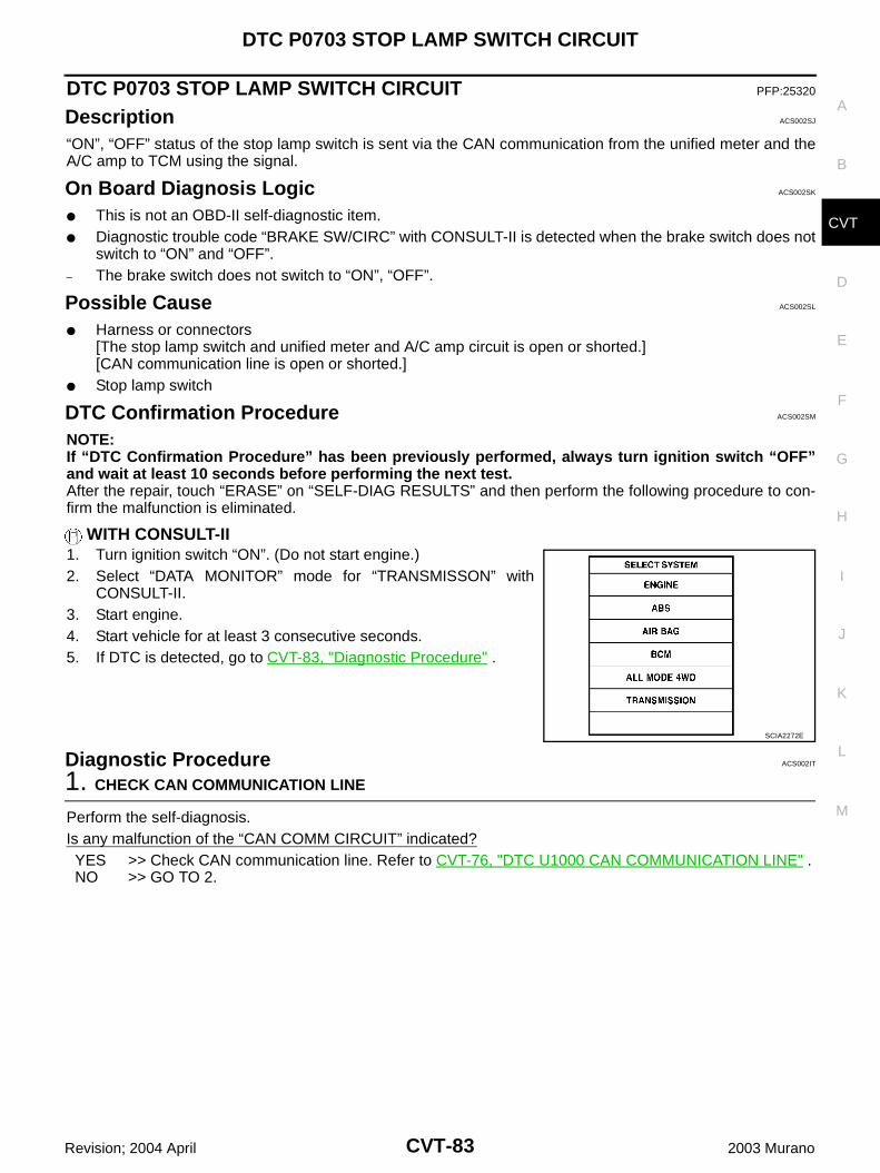
DTC P0703 STOP LAMP SWITCH CIRCUIT
CVT-83
D
E
F
G
H
I
J
K
L
M
A
B
CVT
Revision; 2004 April 2003 Murano
DTC P0703 STOP LAMP SWITCH CIRCUIT PFP:25320
Description ACS002SJ
“ON”, “OFF” status of the stop lamp switch is sent via the CAN communication from the unified meter and theA/C amp to TCM using the signal.
On Board Diagnosis Logic ACS002SK
This is not an OBD-II self-diagnostic item. Diagnostic trouble code “BRAKE SW/CIRC” with CONSULT-II is detected when the brake switch does not
switch to “ON” and “OFF”.– The brake switch does not switch to “ON”, “OFF”.
Possible Cause ACS002SL
Harness or connectors[The stop lamp switch and unified meter and A/C amp circuit is open or shorted.][CAN communication line is open or shorted.]
Stop lamp switch
DTC Confirmation Procedure ACS002SM
NOTE:If “DTC Confirmation Procedure” has been previously performed, always turn ignition switch “OFF”and wait at least 10 seconds before performing the next test.After the repair, touch “ERASE” on “SELF-DIAG RESULTS” and then perform the following procedure to con-firm the malfunction is eliminated.
WITH CONSULT-II1. Turn ignition switch “ON”. (Do not start engine.)2. Select “DATA MONITOR” mode for “TRANSMISSON” with
CONSULT-II.3. Start engine.4. Start vehicle for at least 3 consecutive seconds.5. If DTC is detected, go to CVT-83, "Diagnostic Procedure" .
Diagnostic Procedure ACS002IT
1. CHECK CAN COMMUNICATION LINE
Perform the self-diagnosis.Is any malfunction of the “CAN COMM CIRCUIT” indicated?YES >> Check CAN communication line. Refer to CVT-76, "DTC U1000 CAN COMMUNICATION LINE" .NO >> GO TO 2.
SCIA2272E
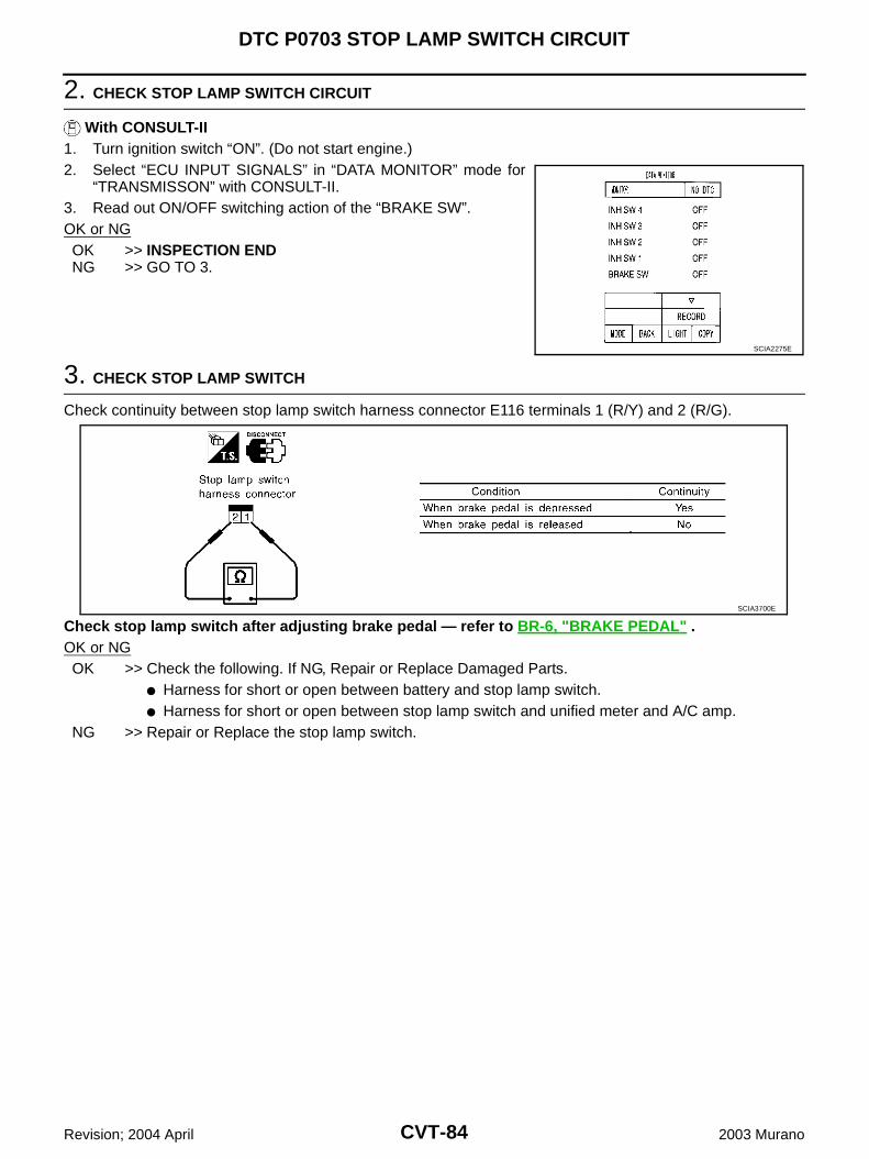
CVT-84
DTC P0703 STOP LAMP SWITCH CIRCUIT
Revision; 2004 April 2003 Murano
2. CHECK STOP LAMP SWITCH CIRCUIT
With CONSULT-II1. Turn ignition switch “ON”. (Do not start engine.)2. Select “ECU INPUT SIGNALS” in “DATA MONITOR” mode for
“TRANSMISSON” with CONSULT-II.3. Read out ON/OFF switching action of the “BRAKE SW”.OK or NGOK >> INSPECTION ENDNG >> GO TO 3.
3. CHECK STOP LAMP SWITCH
Check continuity between stop lamp switch harness connector E116 terminals 1 (R/Y) and 2 (R/G).
Check stop lamp switch after adjusting brake pedal — refer to BR-6, "BRAKE PEDAL" .OK or NGOK >> Check the following. If NG, Repair or Replace Damaged Parts.
Harness for short or open between battery and stop lamp switch. Harness for short or open between stop lamp switch and unified meter and A/C amp.
NG >> Repair or Replace the stop lamp switch.
SCIA2275E
SCIA3700E
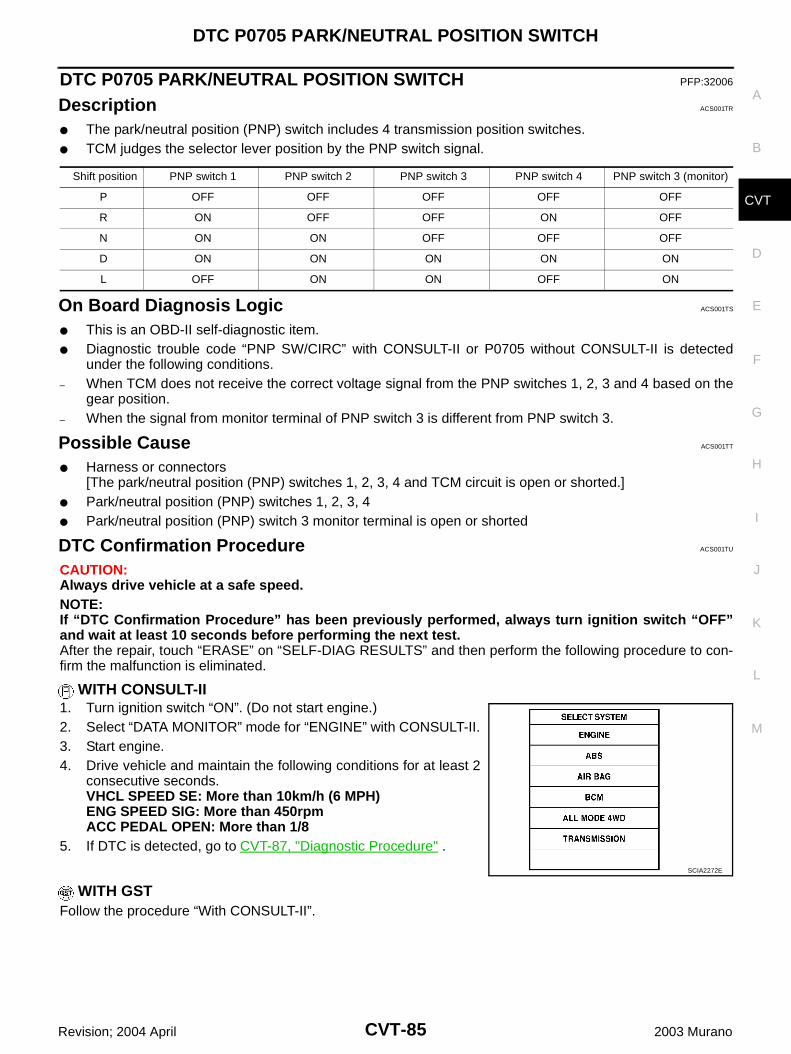
DTC P0705 PARK/NEUTRAL POSITION SWITCH
CVT-85
D
E
F
G
H
I
J
K
L
M
A
B
CVT
Revision; 2004 April 2003 Murano
DTC P0705 PARK/NEUTRAL POSITION SWITCH PFP:32006
Description ACS001TR
The park/neutral position (PNP) switch includes 4 transmission position switches. TCM judges the selector lever position by the PNP switch signal.
On Board Diagnosis Logic ACS001TS
This is an OBD-II self-diagnostic item. Diagnostic trouble code “PNP SW/CIRC” with CONSULT-II or P0705 without CONSULT-II is detected
under the following conditions.– When TCM does not receive the correct voltage signal from the PNP switches 1, 2, 3 and 4 based on the
gear position.– When the signal from monitor terminal of PNP switch 3 is different from PNP switch 3.
Possible Cause ACS001TT
Harness or connectors[The park/neutral position (PNP) switches 1, 2, 3, 4 and TCM circuit is open or shorted.]
Park/neutral position (PNP) switches 1, 2, 3, 4 Park/neutral position (PNP) switch 3 monitor terminal is open or shorted
DTC Confirmation Procedure ACS001TU
CAUTION:Always drive vehicle at a safe speed.NOTE:If “DTC Confirmation Procedure” has been previously performed, always turn ignition switch “OFF”and wait at least 10 seconds before performing the next test.After the repair, touch “ERASE” on “SELF-DIAG RESULTS” and then perform the following procedure to con-firm the malfunction is eliminated.
WITH CONSULT-II1. Turn ignition switch “ON”. (Do not start engine.)2. Select “DATA MONITOR” mode for “ENGINE” with CONSULT-II.3. Start engine.4. Drive vehicle and maintain the following conditions for at least 2
consecutive seconds.VHCL SPEED SE: More than 10km/h (6 MPH)ENG SPEED SIG: More than 450rpmACC PEDAL OPEN: More than 1/8
5. If DTC is detected, go to CVT-87, "Diagnostic Procedure" .
WITH GSTFollow the procedure “With CONSULT-II”.
Shift position PNP switch 1 PNP switch 2 PNP switch 3 PNP switch 4 PNP switch 3 (monitor)
P OFF OFF OFF OFF OFF
R ON OFF OFF ON OFF
N ON ON OFF OFF OFF
D ON ON ON ON ON
L OFF ON ON OFF ON
SCIA2272E
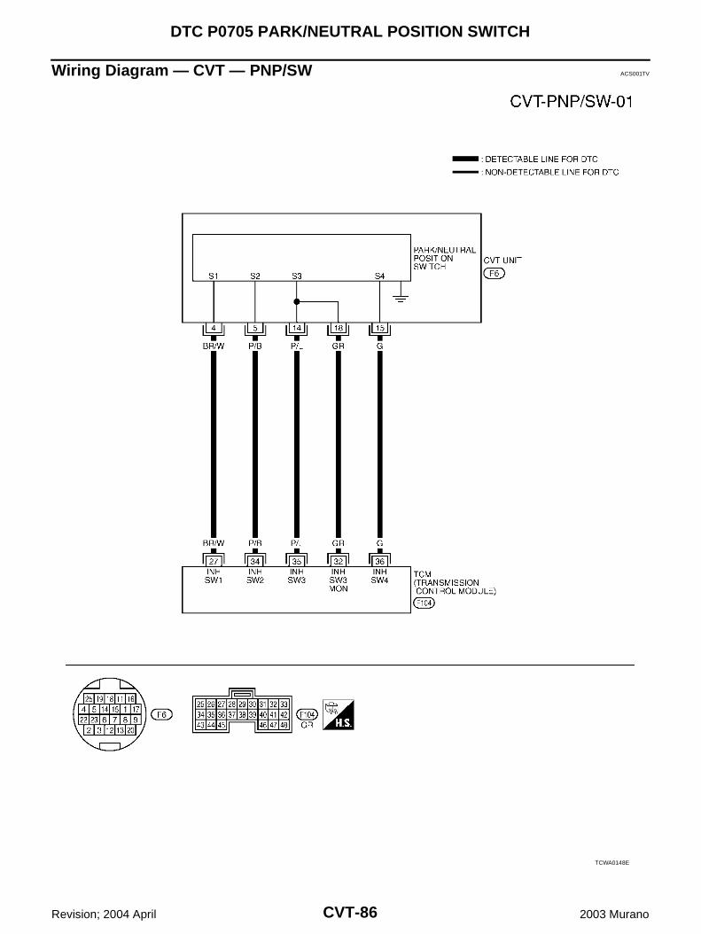
CVT-86
DTC P0705 PARK/NEUTRAL POSITION SWITCH
Revision; 2004 April 2003 Murano
Wiring Diagram — CVT — PNP/SW ACS001TV
TCWA0148E
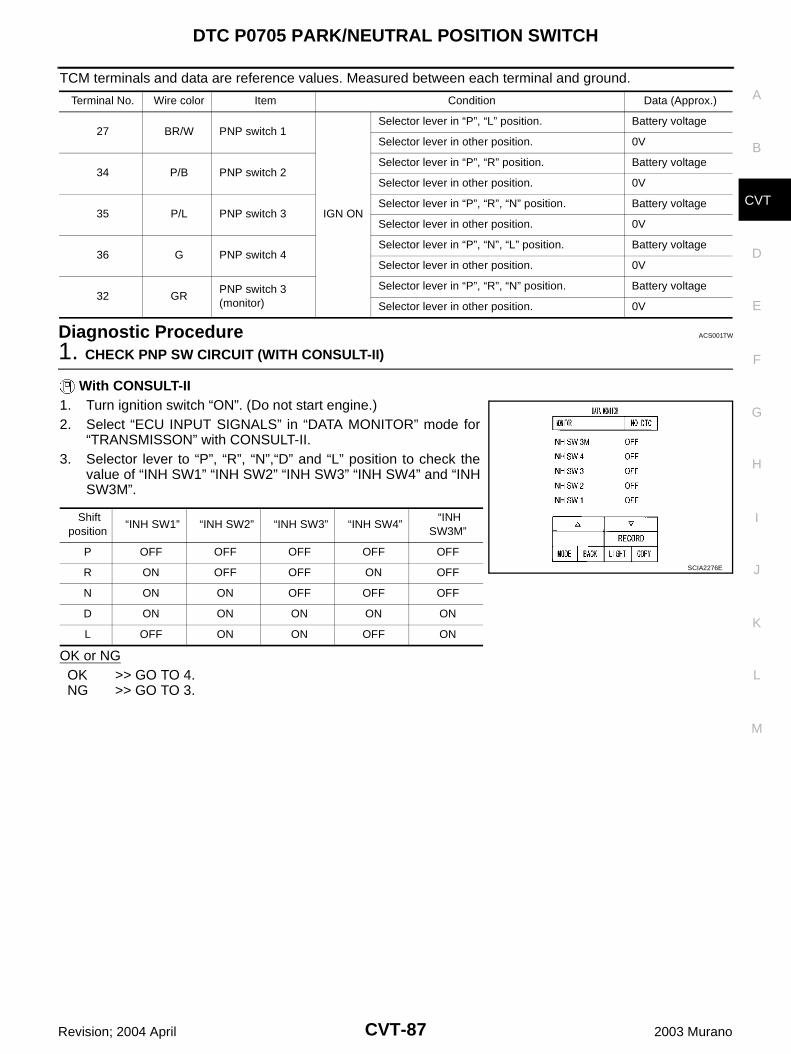
DTC P0705 PARK/NEUTRAL POSITION SWITCH
CVT-87
D
E
F
G
H
I
J
K
L
M
A
B
CVT
Revision; 2004 April 2003 Murano
TCM terminals and data are reference values. Measured between each terminal and ground.
Diagnostic Procedure ACS001TW
1. CHECK PNP SW CIRCUIT (WITH CONSULT-II)
With CONSULT-II1. Turn ignition switch “ON”. (Do not start engine.)2. Select “ECU INPUT SIGNALS” in “DATA MONITOR” mode for
“TRANSMISSON” with CONSULT-II.3. Selector lever to “P”, “R”, “N”,“D” and “L” position to check the
value of “INH SW1” “INH SW2” “INH SW3” “INH SW4” and “INHSW3M”.
OK or NGOK >> GO TO 4.NG >> GO TO 3.
Terminal No. Wire color Item Condition Data (Approx.)
27 BR/W PNP switch 1
IGN ON
Selector lever in “P”, “L” position. Battery voltage
Selector lever in other position. 0V
34 P/B PNP switch 2Selector lever in “P”, “R” position. Battery voltage
Selector lever in other position. 0V
35 P/L PNP switch 3Selector lever in “P”, “R”, “N” position. Battery voltage
Selector lever in other position. 0V
36 G PNP switch 4Selector lever in “P”, “N”, “L” position. Battery voltage
Selector lever in other position. 0V
32 GRPNP switch 3 (monitor)
Selector lever in “P”, “R”, “N” position. Battery voltage
Selector lever in other position. 0V
Shift position
“INH SW1” “INH SW2” “INH SW3” “INH SW4” “INH
SW3M”
P OFF OFF OFF OFF OFF
R ON OFF OFF ON OFF
N ON ON OFF OFF OFF
D ON ON ON ON ON
L OFF ON ON OFF ON
SCIA2276E
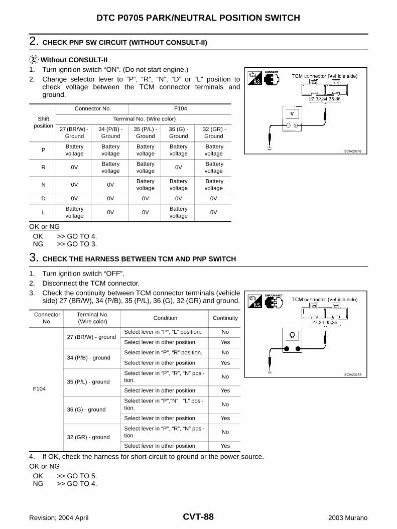
CVT-88
DTC P0705 PARK/NEUTRAL POSITION SWITCH
Revision; 2004 April 2003 Murano
2. CHECK PNP SW CIRCUIT (WITHOUT CONSULT-II)
Without CONSULT-II1. Turn ignition switch “ON”. (Do not start engine.)2. Change selector lever to “P“, “R”, “N”, “D” or “L” position to
check voltage between the TCM connector terminals andground.
OK or NGOK >> GO TO 4.NG >> GO TO 3.
3. CHECK THE HARNESS BETWEEN TCM AND PNP SWITCH
1. Turn ignition switch “OFF”.2. Disconnect the TCM connector.3. Check the continuity between TCM connector terminals (vehicle
side) 27 (BR/W), 34 (P/B), 35 (P/L), 36 (G), 32 (GR) and ground.
4. If OK, check the harness for short-circuit to ground or the power source. OK or NGOK >> GO TO 5.NG >> GO TO 4.
Shift position
Connector No. F104
Terminal No. (Wire color)
27 (BR/W) - Ground
34 (P/B) - Ground
35 (P/L) - Ground
36 (G) - Ground
32 (GR) - Ground
PBattery voltage
Battery voltage
Battery voltage
Battery voltage
Battery voltage
R 0VBattery voltage
Battery voltage
0V Battery voltage
N 0V 0VBattery voltage
Battery voltage
Battery voltage
D 0V 0V 0V 0V 0V
LBattery voltage
0V 0VBattery voltage
0V
SCIA2024E
Connector No.
Terminal No.(Wire color)
Condition Continuity
F104
27 (BR/W) - groundSelect lever in “P”, “L” position. No
Select lever in other position. Yes
34 (P/B) - groundSelect lever in “P”, “R” position. No
Select lever in other position. Yes
35 (P/L) - ground
Select lever in “P”, “R”, “N” posi-tion.
No
Select lever in other position. Yes
36 (G) - ground
Select lever in “P”,“N”, “L” posi-tion.
No
Select lever in other position. Yes
32 (GR) - ground
Select lever in “P”, “R”, “N” posi-tion.
No
Select lever in other position. Yes
SCIA2337E
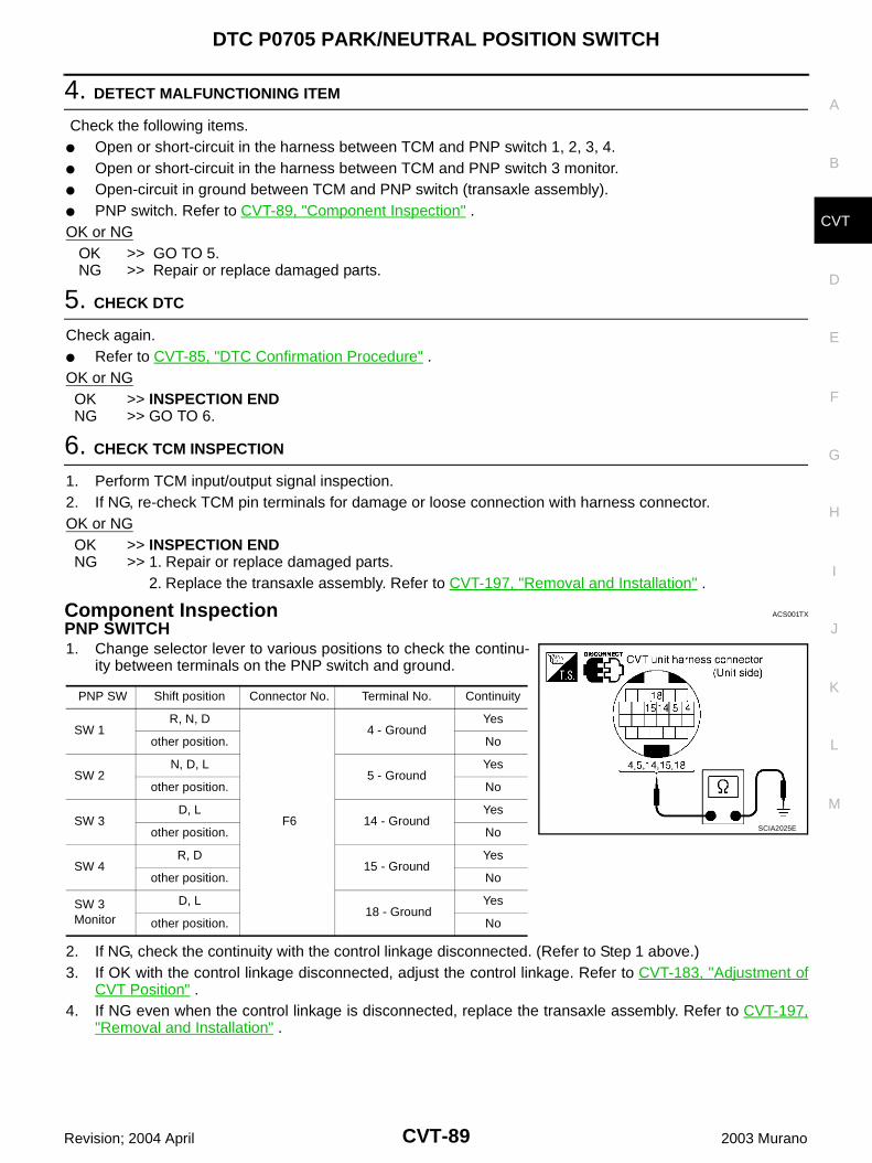
DTC P0705 PARK/NEUTRAL POSITION SWITCH
CVT-89
D
E
F
G
H
I
J
K
L
M
A
B
CVT
Revision; 2004 April 2003 Murano
4. DETECT MALFUNCTIONING ITEM
Check the following items. Open or short-circuit in the harness between TCM and PNP switch 1, 2, 3, 4. Open or short-circuit in the harness between TCM and PNP switch 3 monitor. Open-circuit in ground between TCM and PNP switch (transaxle assembly). PNP switch. Refer to CVT-89, "Component Inspection" .OK or NG OK >> GO TO 5. NG >> Repair or replace damaged parts.
5. CHECK DTC
Check again. Refer to CVT-85, "DTC Confirmation Procedure" .OK or NGOK >> INSPECTION ENDNG >> GO TO 6.
6. CHECK TCM INSPECTION
1. Perform TCM input/output signal inspection.2. If NG, re-check TCM pin terminals for damage or loose connection with harness connector.OK or NGOK >> INSPECTION ENDNG >> 1. Repair or replace damaged parts.
2. Replace the transaxle assembly. Refer to CVT-197, "Removal and Installation" .
Component Inspection ACS001TX
PNP SWITCH1. Change selector lever to various positions to check the continu-
ity between terminals on the PNP switch and ground.
2. If NG, check the continuity with the control linkage disconnected. (Refer to Step 1 above.)3. If OK with the control linkage disconnected, adjust the control linkage. Refer to CVT-183, "Adjustment of
CVT Position" .4. If NG even when the control linkage is disconnected, replace the transaxle assembly. Refer to CVT-197,
"Removal and Installation" .
PNP SW Shift position Connector No. Terminal No. Continuity
SW 1R, N, D
F6
4 - GroundYes
other position. No
SW 2N, D, L
5 - GroundYes
other position. No
SW 3D, L
14 - GroundYes
other position. No
SW 4R, D
15 - GroundYes
other position. No
SW 3 Monitor
D, L 18 - Ground
Yes
other position. No
SCIA2025E
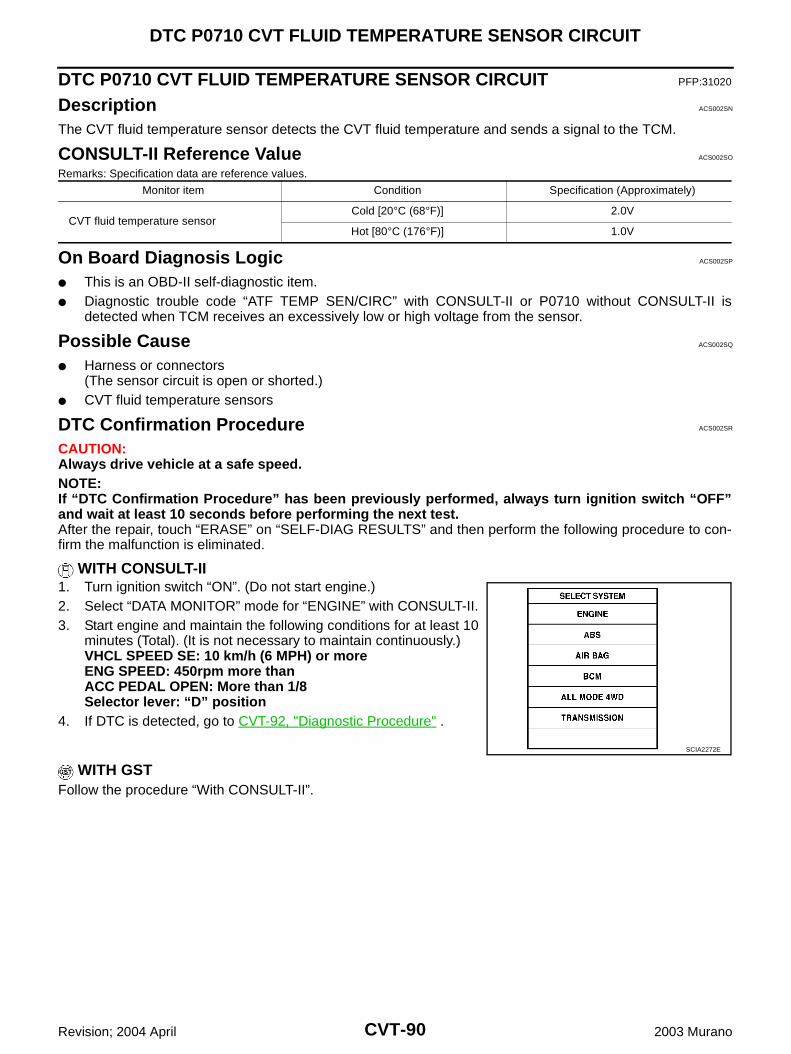
CVT-90
DTC P0710 CVT FLUID TEMPERATURE SENSOR CIRCUIT
Revision; 2004 April 2003 Murano
DTC P0710 CVT FLUID TEMPERATURE SENSOR CIRCUIT PFP:31020
Description ACS002SN
The CVT fluid temperature sensor detects the CVT fluid temperature and sends a signal to the TCM.
CONSULT-II Reference Value ACS002SO
Remarks: Specification data are reference values.
On Board Diagnosis Logic ACS002SP
This is an OBD-II self-diagnostic item. Diagnostic trouble code “ATF TEMP SEN/CIRC” with CONSULT-II or P0710 without CONSULT-II is
detected when TCM receives an excessively low or high voltage from the sensor.
Possible Cause ACS002SQ
Harness or connectors(The sensor circuit is open or shorted.)
CVT fluid temperature sensors
DTC Confirmation Procedure ACS002SR
CAUTION:Always drive vehicle at a safe speed.NOTE:If “DTC Confirmation Procedure” has been previously performed, always turn ignition switch “OFF”and wait at least 10 seconds before performing the next test.After the repair, touch “ERASE” on “SELF-DIAG RESULTS” and then perform the following procedure to con-firm the malfunction is eliminated.
WITH CONSULT-II1. Turn ignition switch “ON”. (Do not start engine.)2. Select “DATA MONITOR” mode for “ENGINE” with CONSULT-II.3. Start engine and maintain the following conditions for at least 10
minutes (Total). (It is not necessary to maintain continuously.)VHCL SPEED SE: 10 km/h (6 MPH) or moreENG SPEED: 450rpm more thanACC PEDAL OPEN: More than 1/8Selector lever: “D” position
4. If DTC is detected, go to CVT-92, "Diagnostic Procedure" .
WITH GSTFollow the procedure “With CONSULT-II”.
Monitor item Condition Specification (Approximately)
CVT fluid temperature sensor Cold [20°C (68°F)] 2.0V
Hot [80°C (176°F)] 1.0V
SCIA2272E
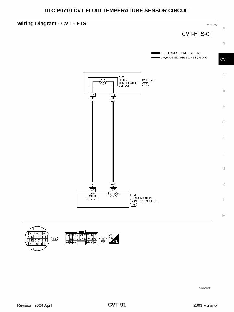
DTC P0710 CVT FLUID TEMPERATURE SENSOR CIRCUIT
CVT-91
D
E
F
G
H
I
J
K
L
M
A
B
CVT
Revision; 2004 April 2003 Murano
Wiring Diagram - CVT - FTS ACS0020Q
TCWA0149E
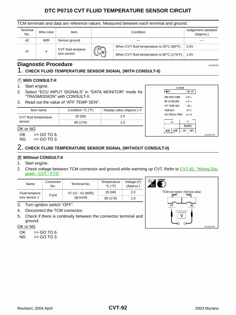
CVT-92
DTC P0710 CVT FLUID TEMPERATURE SENSOR CIRCUIT
Revision; 2004 April 2003 Murano
TCM terminals and data are reference values. Measured between each terminal and ground.
Diagnostic Procedure ACS002SS
1. CHECK FLUID TEMPERATURE SENSOR SIGNAL (WITH CONSULT-II)
With CONSULT-II1. Start engine.2. Select “ECU INPUT SIGNALS” in “DATA MONITOR” mode for
“TRASMISSION” with CONSULT-II.3. Read out the value of “ATF TEMP SEN”.
OK or NGOK >> GO TO 6.NG >> GO TO 3.
2. CHECK FLUID TEMPERATURE SENSOR SIGNAL (WITHOUT CONSULT-II)
Without CONSULT-II1. Start engine.2. Check voltage between TCM connector and ground while warming up CVT. Refer to CVT-91, "Wiring Dia-
gram - CVT - FTS" .
3. Turn ignition switch “OFF”.4. Disconnect the TCM connector.5. Check if there is continuity between the connector terminal and
ground.OK or NGOK >> GO TO 6.NG >> GO TO 3.
Terminal No.
Wire color Item ConditionJudgement standard
(Approx.)
42 W/R Sensor ground — —
47 VCVT fluid tempera-ture sensor
When CVT fluid temperature is 20°C (68°F). 2.0V
When CVT fluid temperature is 80°C (176°F). 1.0V
Item name Condition °C (°F) Display value (Approx.) V
CVT fluid temperature sensor
20 (68) 2.0
80 (176) 1.0
SCIA2277E
NameConnector
No.Terminal No.
Temperature °C (°F)
Voltage (V) (Approx.)
Fluid tempera-ture sensor 1
F10447 (V) - 42 (W/R)
(ground)
20 (68) 2.0
80 (176) 1.0
SCIA2027E
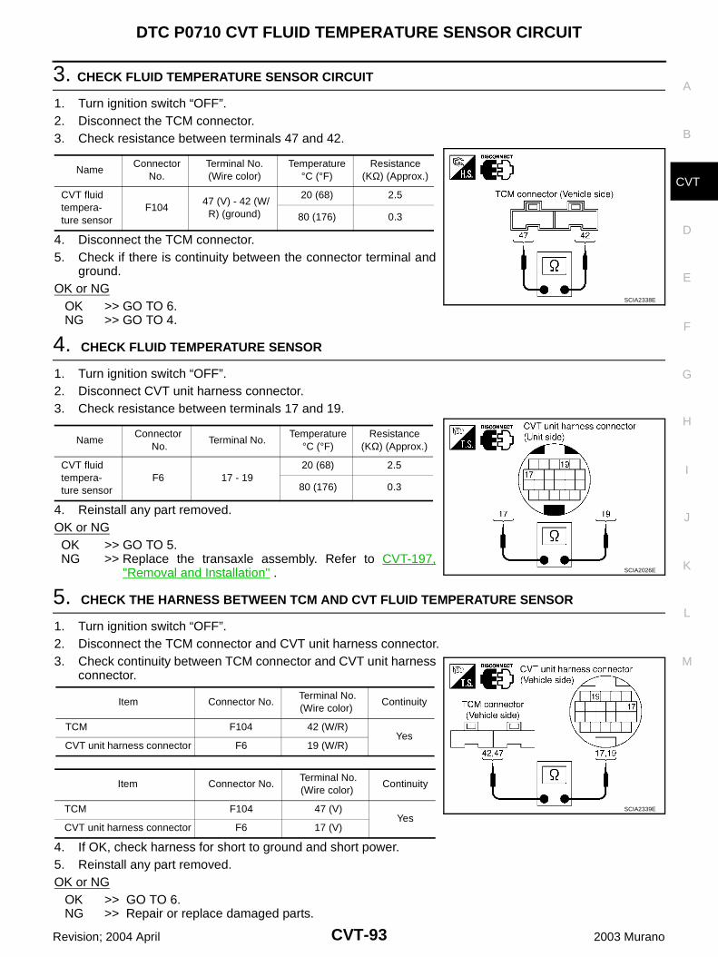
DTC P0710 CVT FLUID TEMPERATURE SENSOR CIRCUIT
CVT-93
D
E
F
G
H
I
J
K
L
M
A
B
CVT
Revision; 2004 April 2003 Murano
3. CHECK FLUID TEMPERATURE SENSOR CIRCUIT
1. Turn ignition switch “OFF”.2. Disconnect the TCM connector.3. Check resistance between terminals 47 and 42.
4. Disconnect the TCM connector.5. Check if there is continuity between the connector terminal and
ground.OK or NG OK >> GO TO 6. NG >> GO TO 4.
4. CHECK FLUID TEMPERATURE SENSOR
1. Turn ignition switch “OFF”.2. Disconnect CVT unit harness connector.3. Check resistance between terminals 17 and 19.
4. Reinstall any part removed.OK or NGOK >> GO TO 5.NG >> Replace the transaxle assembly. Refer to CVT-197,
"Removal and Installation" .
5. CHECK THE HARNESS BETWEEN TCM AND CVT FLUID TEMPERATURE SENSOR
1. Turn ignition switch “OFF”.2. Disconnect the TCM connector and CVT unit harness connector.3. Check continuity between TCM connector and CVT unit harness
connector.
4. If OK, check harness for short to ground and short power.5. Reinstall any part removed.OK or NG OK >> GO TO 6. NG >> Repair or replace damaged parts.
NameConnector
No.Terminal No. (Wire color)
Temperature °C (°F)
Resistance (KΩ) (Approx.)
CVT fluid tempera-ture sensor
F104 47 (V) - 42 (W/
R) (ground)
20 (68) 2.5
80 (176) 0.3
SCIA2338E
NameConnector
No.Terminal No.
Temperature °C (°F)
Resistance (KΩ) (Approx.)
CVT fluid tempera-ture sensor
F6 17 - 1920 (68) 2.5
80 (176) 0.3
SCIA2026E
Item Connector No. Terminal No. (Wire color)
Continuity
TCM F104 42 (W/R) Yes
CVT unit harness connector F6 19 (W/R)
Item Connector No. Terminal No. (Wire color)
Continuity
TCM F104 47 (V) Yes
CVT unit harness connector F6 17 (V)
SCIA2339E
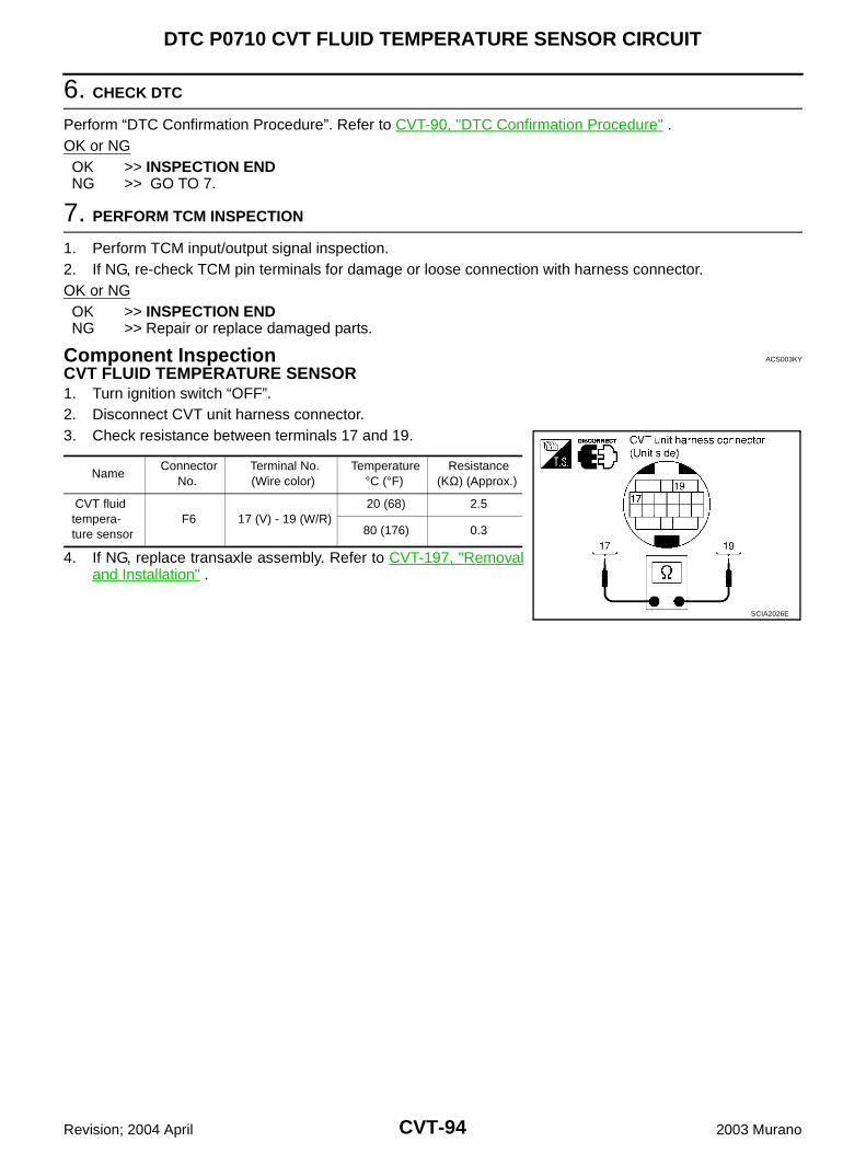
CVT-94
DTC P0710 CVT FLUID TEMPERATURE SENSOR CIRCUIT
Revision; 2004 April 2003 Murano
6. CHECK DTC
Perform “DTC Confirmation Procedure”. Refer to CVT-90, "DTC Confirmation Procedure" .OK or NGOK >> INSPECTION ENDNG >> GO TO 7.
7. PERFORM TCM INSPECTION
1. Perform TCM input/output signal inspection.2. If NG, re-check TCM pin terminals for damage or loose connection with harness connector.OK or NGOK >> INSPECTION ENDNG >> Repair or replace damaged parts.
Component Inspection ACS003KY
CVT FLUID TEMPERATURE SENSOR1. Turn ignition switch “OFF”.2. Disconnect CVT unit harness connector.3. Check resistance between terminals 17 and 19.
4. If NG, replace transaxle assembly. Refer to CVT-197, "Removaland Installation" .
Name Connector
No. Terminal No. (Wire color)
Temperature °C (°F)
Resistance (KΩ) (Approx.)
CVT fluid tempera-ture sensor
F6 17 (V) - 19 (W/R) 20 (68) 2.5
80 (176) 0.3
SCIA2026E
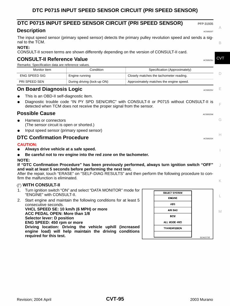
DTC P0715 INPUT SPEED SENSOR CIRCUIT (PRI SPEED SENSOR)
CVT-95
D
E
F
G
H
I
J
K
L
M
A
B
CVT
Revision; 2004 April 2003 Murano
DTC P0715 INPUT SPEED SENSOR CIRCUIT (PRI SPEED SENSOR) PFP:31935
Description ACS002ST
The input speed sensor (primary speed sensor) detects the primary pulley revolution speed and sends a sig-nal to the TCM.NOTE:CONSULT-II screen terms are shown differently depending on the version of CONSULT-II card.
CONSULT-II Reference Value ACS002SU
Remarks: Specification data are reference values.
On Board Diagnosis Logic ACS002SV
This is an OBD-II self-diagnostic item. Diagnostic trouble code “IN PY SPD SEN/CIRC” with CONSULT-II or P0715 without CONSULT-II is
detected when TCM does not receive the proper signal from the sensor.
Possible Cause ACS002SW
Harness or connectors(The sensor circuit is open or shorted.)
Input speed sensor (primary speed sensor)
DTC Confirmation Procedure ACS002SX
CAUTION: Always drive vehicle at a safe speed. Be careful not to rev engine into the red zone on the tachometer.NOTE:If “DTC Confirmation Procedure” has been previously performed, always turn ignition switch “OFF”and wait at least 5 seconds before performing the next test.After the repair, touch “ERASE” on “SELF-DIAG RESULTS” and then perform the following procedure to con-firm the malfunction is eliminated.
WITH CONSULT-II1. Turn ignition switch “ON” and select “DATA MONITOR” mode for
“ENGINE” with CONSULT-II.2. Start engine and maintain the following conditions for at least 5
consecutive seconds.VHCL SPEED SE: 10 km/h (6 MPH) or moreACC PEDAL OPEN: More than 1/8Selector lever: D positionENG SPEED: 450 rpm or moreDriving location: Driving the vehicle uphill (increasedengine load) will help maintain the driving conditionsrequired for this test.
Monitor item Condition Specification (Approximately)
ENG SPEED SIG Engine running Closely matches the tachometer reading.
PRI SPEED SEN During driving (lock-up ON) Approximately matches the engine speed.
SCIA2272E
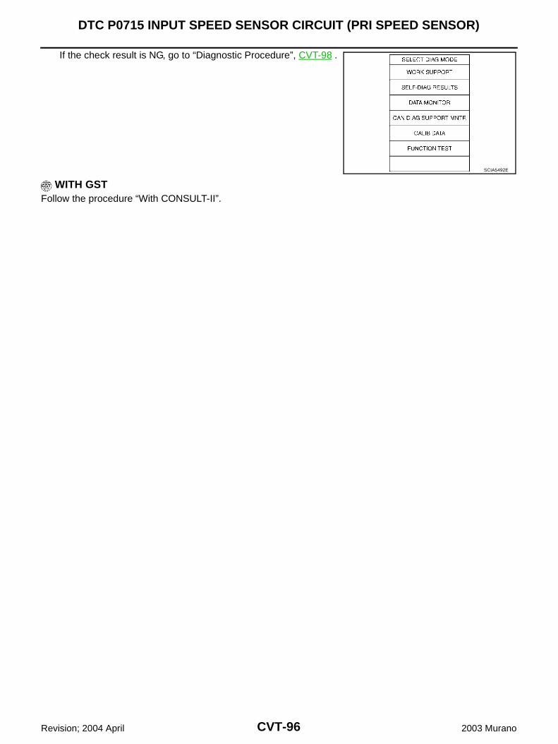
CVT-96
DTC P0715 INPUT SPEED SENSOR CIRCUIT (PRI SPEED SENSOR)
Revision; 2004 April 2003 Murano
If the check result is NG, go to “Diagnostic Procedure”, CVT-98 .
WITH GSTFollow the procedure “With CONSULT-II”.
SCIA5492E
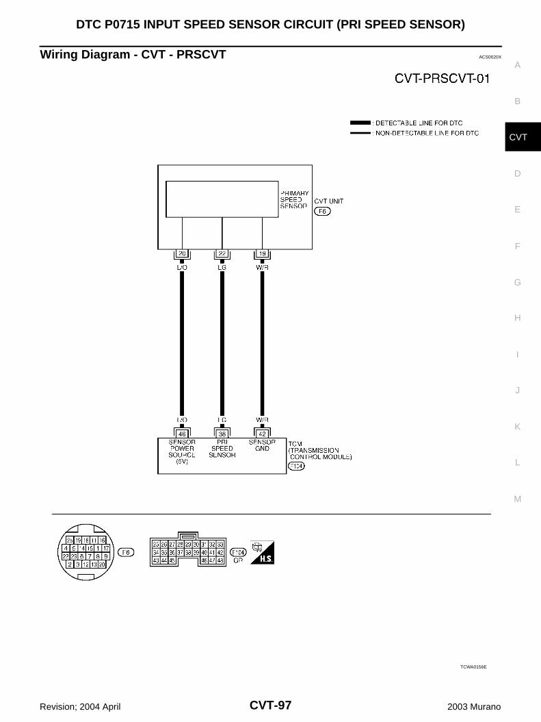
DTC P0715 INPUT SPEED SENSOR CIRCUIT (PRI SPEED SENSOR)
CVT-97
D
E
F
G
H
I
J
K
L
M
A
B
CVT
Revision; 2004 April 2003 Murano
Wiring Diagram - CVT - PRSCVT ACS0020X
TCWA0156E
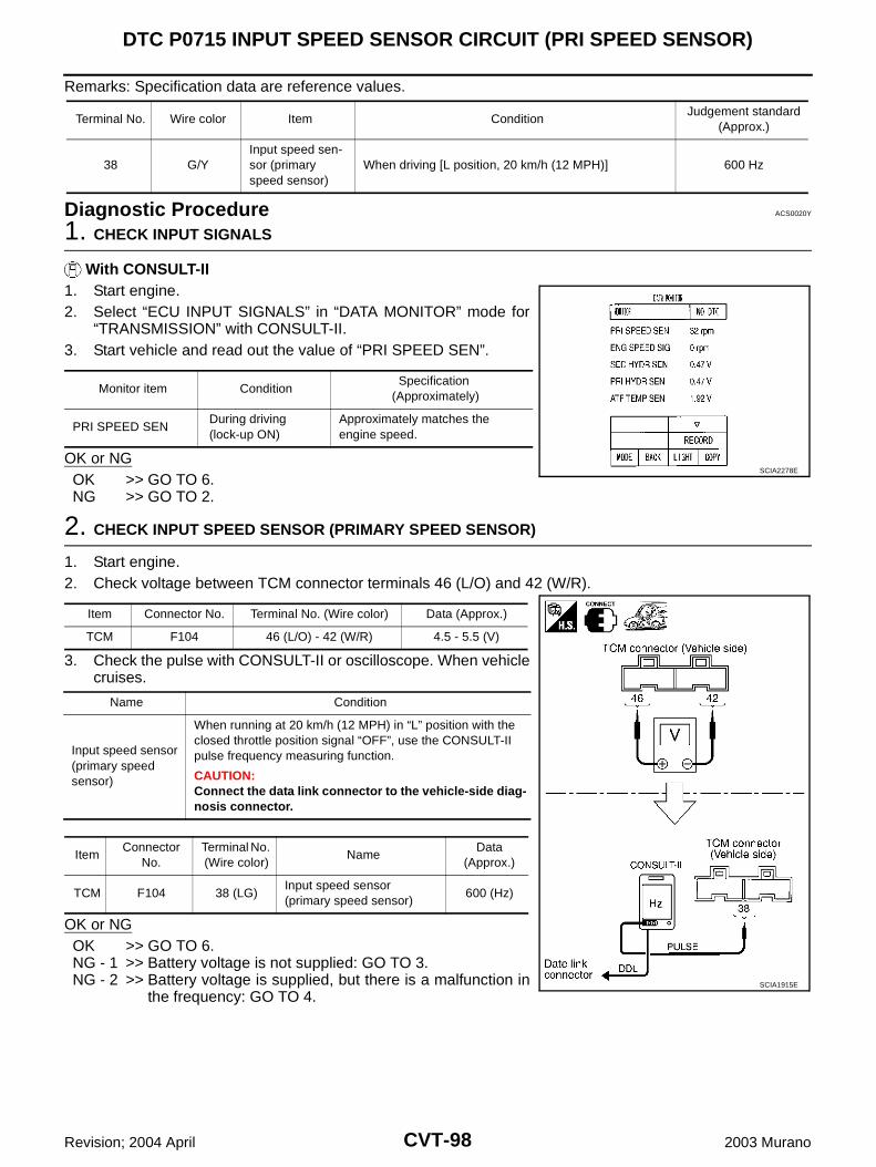
CVT-98
DTC P0715 INPUT SPEED SENSOR CIRCUIT (PRI SPEED SENSOR)
Revision; 2004 April 2003 Murano
Remarks: Specification data are reference values.
Diagnostic Procedure ACS0020Y
1. CHECK INPUT SIGNALS
With CONSULT-II1. Start engine.2. Select “ECU INPUT SIGNALS” in “DATA MONITOR” mode for
“TRANSMISSION” with CONSULT-II.3. Start vehicle and read out the value of “PRI SPEED SEN”.
OK or NGOK >> GO TO 6.NG >> GO TO 2.
2. CHECK INPUT SPEED SENSOR (PRIMARY SPEED SENSOR)
1. Start engine.2. Check voltage between TCM connector terminals 46 (L/O) and 42 (W/R).
3. Check the pulse with CONSULT-II or oscilloscope. When vehiclecruises.
OK or NGOK >> GO TO 6.NG - 1 >> Battery voltage is not supplied: GO TO 3.NG - 2 >> Battery voltage is supplied, but there is a malfunction in
the frequency: GO TO 4.
Terminal No. Wire color Item ConditionJudgement standard
(Approx.)
38 G/YInput speed sen-sor (primary speed sensor)
When driving [L position, 20 km/h (12 MPH)] 600 Hz
Monitor item ConditionSpecification
(Approximately)
PRI SPEED SEN During driving (lock-up ON)
Approximately matches the engine speed.
SCIA2278E
Item Connector No. Terminal No. (Wire color) Data (Approx.)
TCM F104 46 (L/O) - 42 (W/R) 4.5 - 5.5 (V)
Name Condition
Input speed sensor (primary speed sensor)
When running at 20 km/h (12 MPH) in “L” position with the closed throttle position signal “OFF”, use the CONSULT-II pulse frequency measuring function.
CAUTION:Connect the data link connector to the vehicle-side diag-nosis connector.
ItemConnector
No.Terminal No. (Wire color)
NameData
(Approx.)
TCM F104 38 (LG)Input speed sensor(primary speed sensor)
600 (Hz)
SCIA1915E
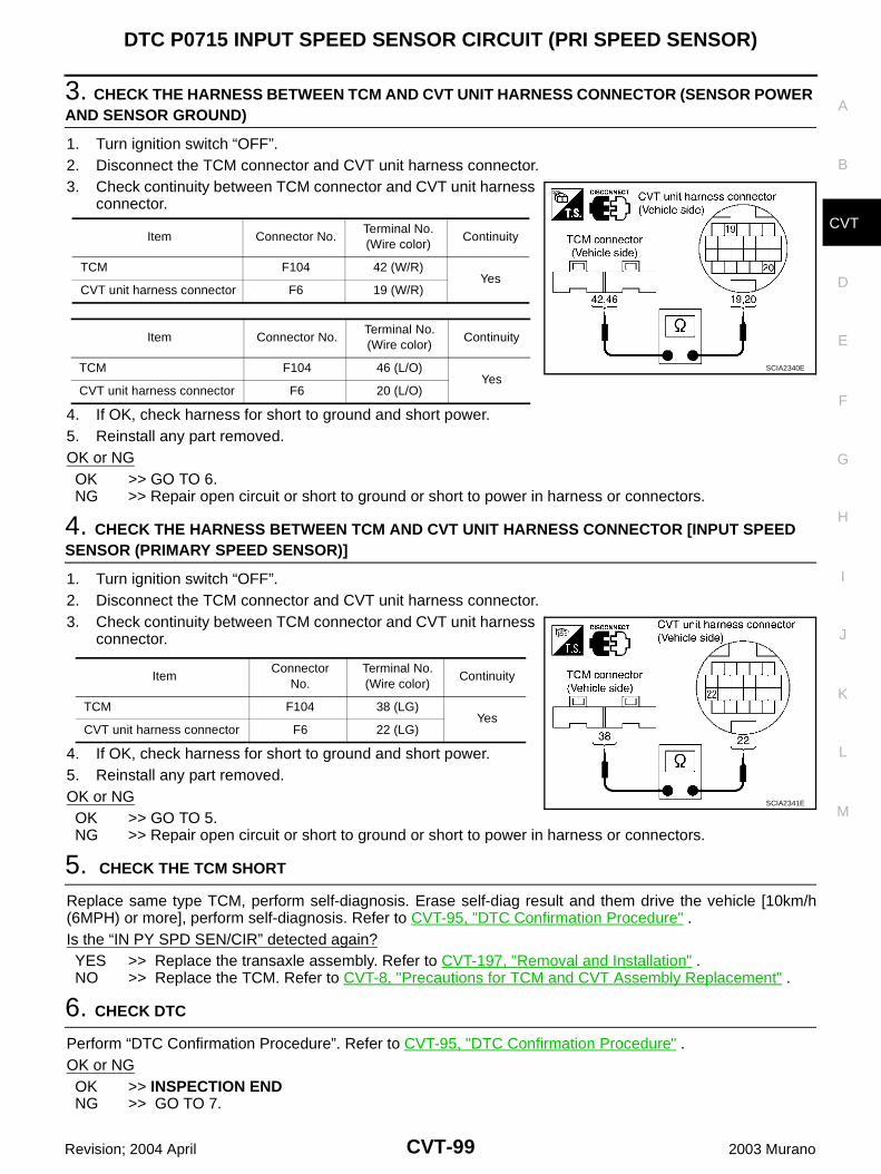
DTC P0715 INPUT SPEED SENSOR CIRCUIT (PRI SPEED SENSOR)
CVT-99
D
E
F
G
H
I
J
K
L
M
A
B
CVT
Revision; 2004 April 2003 Murano
3. CHECK THE HARNESS BETWEEN TCM AND CVT UNIT HARNESS CONNECTOR (SENSOR POWER AND SENSOR GROUND)
1. Turn ignition switch “OFF”.2. Disconnect the TCM connector and CVT unit harness connector.3. Check continuity between TCM connector and CVT unit harness
connector.
4. If OK, check harness for short to ground and short power.5. Reinstall any part removed.OK or NGOK >> GO TO 6.NG >> Repair open circuit or short to ground or short to power in harness or connectors.
4. CHECK THE HARNESS BETWEEN TCM AND CVT UNIT HARNESS CONNECTOR [INPUT SPEED SENSOR (PRIMARY SPEED SENSOR)]
1. Turn ignition switch “OFF”.2. Disconnect the TCM connector and CVT unit harness connector.3. Check continuity between TCM connector and CVT unit harness
connector.
4. If OK, check harness for short to ground and short power.5. Reinstall any part removed.OK or NGOK >> GO TO 5.NG >> Repair open circuit or short to ground or short to power in harness or connectors.
5. CHECK THE TCM SHORT
Replace same type TCM, perform self-diagnosis. Erase self-diag result and them drive the vehicle [10km/h(6MPH) or more], perform self-diagnosis. Refer to CVT-95, "DTC Confirmation Procedure" .Is the “IN PY SPD SEN/CIR” detected again?YES >> Replace the transaxle assembly. Refer to CVT-197, "Removal and Installation" .NO >> Replace the TCM. Refer to CVT-8, "Precautions for TCM and CVT Assembly Replacement" .
6. CHECK DTC
Perform “DTC Confirmation Procedure”. Refer to CVT-95, "DTC Confirmation Procedure" .OK or NGOK >> INSPECTION ENDNG >> GO TO 7.
Item Connector No.Terminal No. (Wire color)
Continuity
TCM F104 42 (W/R)Yes
CVT unit harness connector F6 19 (W/R)
Item Connector No.Terminal No. (Wire color)
Continuity
TCM F104 46 (L/O)Yes
CVT unit harness connector F6 20 (L/O)
SCIA2340E
ItemConnector
No.Terminal No. (Wire color)
Continuity
TCM F104 38 (LG)Yes
CVT unit harness connector F6 22 (LG)
SCIA2341E
CVT-100
DTC P0715 INPUT SPEED SENSOR CIRCUIT (PRI SPEED SENSOR)
Revision; 2004 April 2003 Murano
7. PERFORM TCM INSPECTION
1. Perform TCM input/output signal inspection.2. If NG, re-check TCM pin terminals for damage or loose connection with harness connector.OK or NGOK >> INSPECTION ENDNG >> Repair or replace damaged parts.

DTC P0720 VEHICLE SPEED SENSOR CVT (SECONDARY SPEED SENSOR)
CVT-101
D
E
F
G
H
I
J
K
L
M
A
B
CVT
Revision; 2004 April 2003 Murano
DTC P0720 VEHICLE SPEED SENSOR CVT (SECONDARY SPEED SENSOR)PFP:31935
Description ACS002SY
The vehicle speed sensor CVT [output speed sensor (secondary speed sensor)] detects the revolution of theCVT output shaft and emits a pulse signal. The pulse signal is sent to the TCM, which converts it into vehiclespeed.NOTE:CONSULT-II screen terms are shown differently depending on the version of CONSULT-II card.
CONSULT-II Reference Value ACS002SZ
Remarks: Specification data are reference values.
On Board Diagnosis Logic ACS002T0
This is an OBD-II self-diagnostic item. Diagnostic trouble code “VEH SPD SEN/CIR AT” with CONSULT-II or P0720 without CONSULT-II is
detected TCM does not receive the proper signal from the sensor.
Possible Cause ACS002T1
Harness or connectors(The sensor circuit is open or shorted.)
Output speed sensor (secondary speed sensor)
DTC Confirmation Procedure ACS002T2
CAUTION: Always drive vehicle at a safe speed. Be careful not to rev engine into the red zone on the tachometer.NOTE:If “DTC Confirmation Procedure” has been previously performed, always turn ignition switch “OFF”and wait at least 5 seconds before performing the next test.After the repair, touch “ERASE” on “SELF-DIAG RESULTS” and then perform the following procedure to con-firm the malfunction is eliminated.
WITH CONSULT-II1. Turn ignition switch “ON” and select “DATA MONITOR” mode for
“ENGINE” with CONSULT-II.2. Start engine and maintain the following conditions for at least 12
consecutive seconds.ACC PEDAL OPEN: More than 1/8Selector lever: D positionDriving location: Driving the vehicle uphill (increasedengine load) will help maintain the driving conditionsrequired for this test.
Monitor item Condition Specification (Approximately)
Vehicle speed During driving Approximately matches the speedometer reading.
SCIA2272E
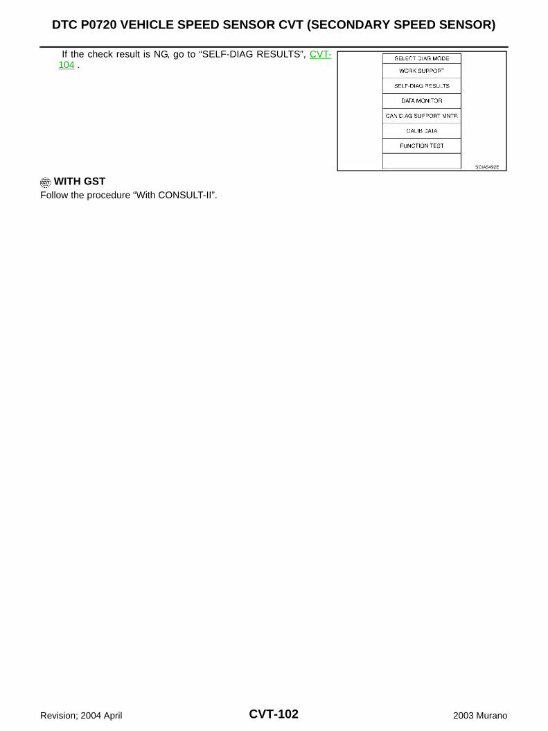
CVT-102
DTC P0720 VEHICLE SPEED SENSOR CVT (SECONDARY SPEED SENSOR)
Revision; 2004 April 2003 Murano
If the check result is NG, go to “SELF-DIAG RESULTS”, CVT-104 .
WITH GSTFollow the procedure “With CONSULT-II”.
SCIA5492E
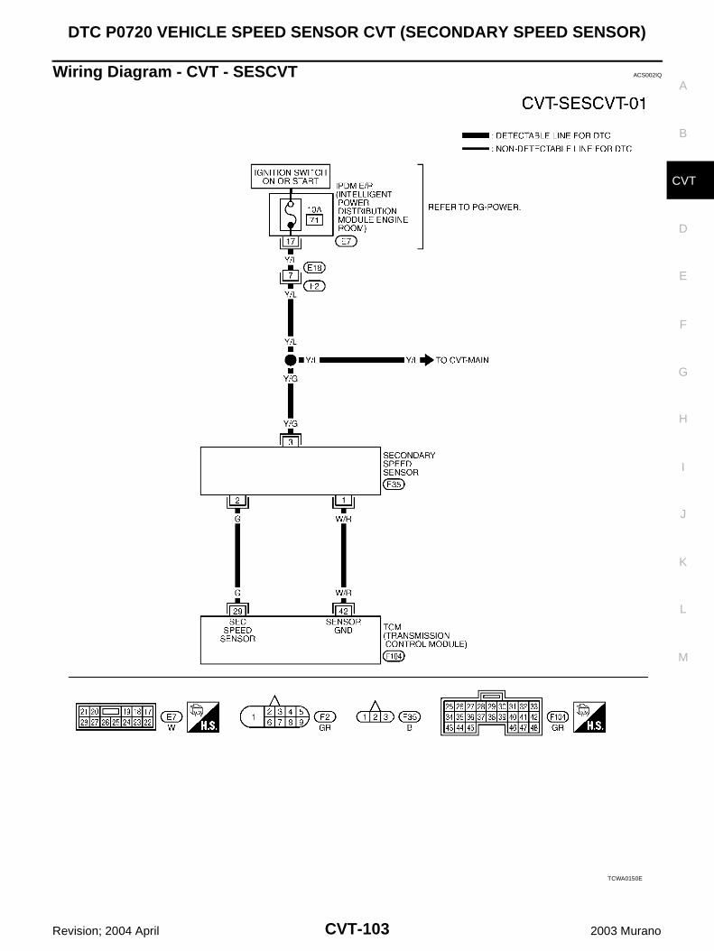
DTC P0720 VEHICLE SPEED SENSOR CVT (SECONDARY SPEED SENSOR)
CVT-103
D
E
F
G
H
I
J
K
L
M
A
B
CVT
Revision; 2004 April 2003 Murano
Wiring Diagram - CVT - SESCVT ACS002IQ
TCWA0150E
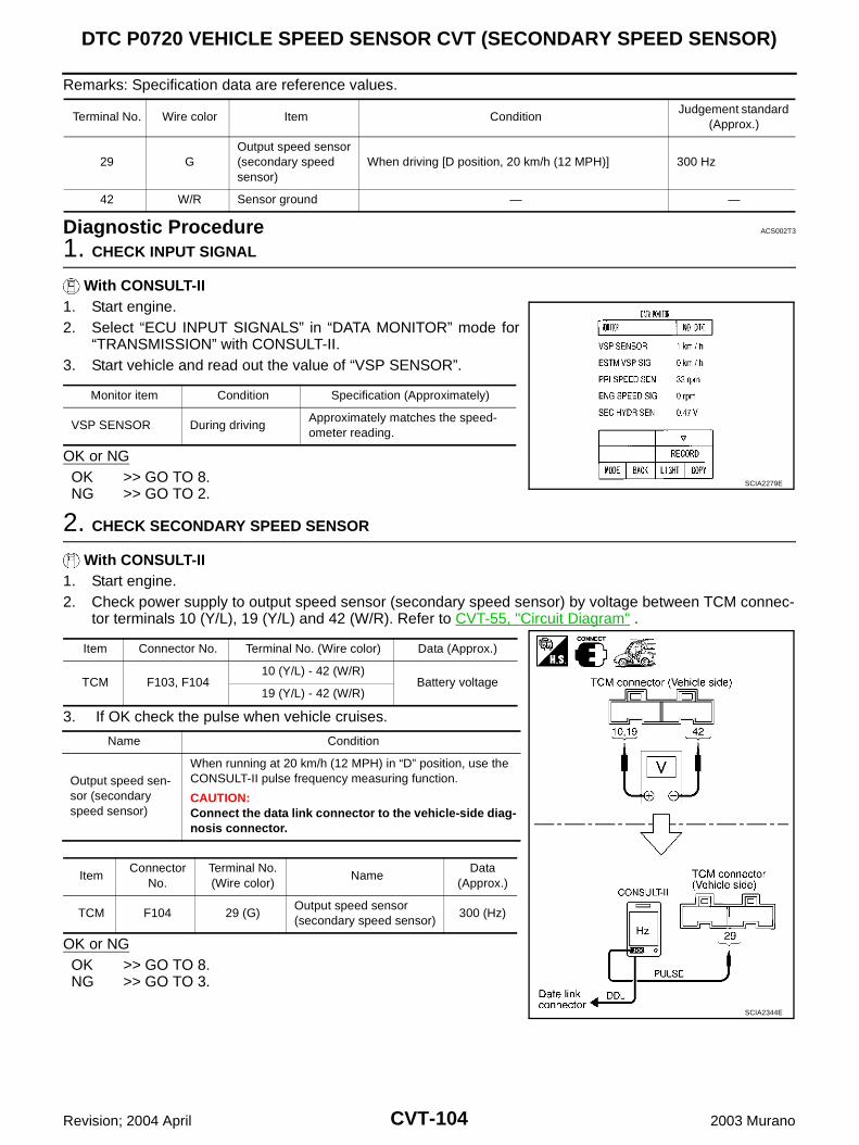
CVT-104
DTC P0720 VEHICLE SPEED SENSOR CVT (SECONDARY SPEED SENSOR)
Revision; 2004 April 2003 Murano
Remarks: Specification data are reference values.
Diagnostic Procedure ACS002T3
1. CHECK INPUT SIGNAL
With CONSULT-II1. Start engine.2. Select “ECU INPUT SIGNALS” in “DATA MONITOR” mode for
“TRANSMISSION” with CONSULT-II.3. Start vehicle and read out the value of “VSP SENSOR”.
OK or NGOK >> GO TO 8.NG >> GO TO 2.
2. CHECK SECONDARY SPEED SENSOR
With CONSULT-II1. Start engine.2. Check power supply to output speed sensor (secondary speed sensor) by voltage between TCM connec-
tor terminals 10 (Y/L), 19 (Y/L) and 42 (W/R). Refer to CVT-55, "Circuit Diagram" .
3. If OK check the pulse when vehicle cruises.
OK or NGOK >> GO TO 8.NG >> GO TO 3.
Terminal No. Wire color Item ConditionJudgement standard
(Approx.)
29 GOutput speed sensor (secondary speed sensor)
When driving [D position, 20 km/h (12 MPH)] 300 Hz
42 W/R Sensor ground — —
Monitor item Condition Specification (Approximately)
VSP SENSOR During drivingApproximately matches the speed-ometer reading.
SCIA2279E
Item Connector No. Terminal No. (Wire color) Data (Approx.)
TCM F103, F10410 (Y/L) - 42 (W/R)
Battery voltage19 (Y/L) - 42 (W/R)
Name Condition
Output speed sen-sor (secondary speed sensor)
When running at 20 km/h (12 MPH) in “D” position, use the CONSULT-II pulse frequency measuring function.
CAUTION:Connect the data link connector to the vehicle-side diag-nosis connector.
ItemConnector
No.Terminal No.(Wire color)
NameData
(Approx.)
TCM F104 29 (G)Output speed sensor(secondary speed sensor)
300 (Hz)
SCIA2344E
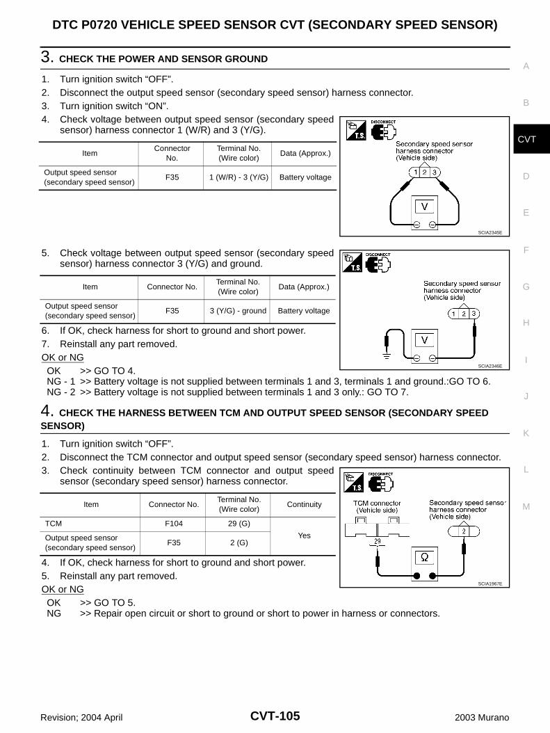
DTC P0720 VEHICLE SPEED SENSOR CVT (SECONDARY SPEED SENSOR)
CVT-105
D
E
F
G
H
I
J
K
L
M
A
B
CVT
Revision; 2004 April 2003 Murano
3. CHECK THE POWER AND SENSOR GROUND
1. Turn ignition switch “OFF”.2. Disconnect the output speed sensor (secondary speed sensor) harness connector.3. Turn ignition switch “ON”.4. Check voltage between output speed sensor (secondary speed
sensor) harness connector 1 (W/R) and 3 (Y/G).
5. Check voltage between output speed sensor (secondary speedsensor) harness connector 3 (Y/G) and ground.
6. If OK, check harness for short to ground and short power.7. Reinstall any part removed.OK or NGOK >> GO TO 4.NG - 1 >> Battery voltage is not supplied between terminals 1 and 3, terminals 1 and ground.:GO TO 6.NG - 2 >> Battery voltage is not supplied between terminals 1 and 3 only.: GO TO 7.
4. CHECK THE HARNESS BETWEEN TCM AND OUTPUT SPEED SENSOR (SECONDARY SPEED SENSOR)
1. Turn ignition switch “OFF”.2. Disconnect the TCM connector and output speed sensor (secondary speed sensor) harness connector.3. Check continuity between TCM connector and output speed
sensor (secondary speed sensor) harness connector.
4. If OK, check harness for short to ground and short power.5. Reinstall any part removed.OK or NGOK >> GO TO 5.NG >> Repair open circuit or short to ground or short to power in harness or connectors.
ItemConnector
No.Terminal No. (Wire color)
Data (Approx.)
Output speed sensor (secondary speed sensor)
F35 1 (W/R) - 3 (Y/G) Battery voltage
SCIA2345E
Item Connector No.Terminal No. (Wire color)
Data (Approx.)
Output speed sensor (secondary speed sensor)
F35 3 (Y/G) - ground Battery voltage
SCIA2346E
Item Connector No.Terminal No. (Wire color)
Continuity
TCM F104 29 (G)
YesOutput speed sensor (secondary speed sensor)
F35 2 (G)
SCIA1967E
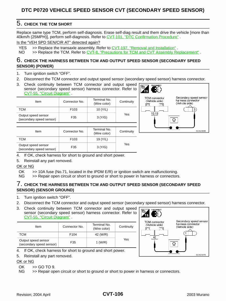
CVT-106
DTC P0720 VEHICLE SPEED SENSOR CVT (SECONDARY SPEED SENSOR)
Revision; 2004 April 2003 Murano
5. CHECK THE TCM SHORT
Replace same type TCM, perform self-diagnosis. Erase self-diag result and them drive the vehicle [more than40km/h (25MPH)], perform self-diagnosis. Refer to CVT-101, "DTC Confirmation Procedure" .Is the “VEH SPD SEN/CIR AT” detected again?YES >> Replace the transaxle assembly. Refer to CVT-197, "Removal and Installation" .NO >> Replace the TCM. Refer to CVT-8, "Precautions for TCM and CVT Assembly Replacement" .
6. CHECK THE HARNESS BETWEEN TCM AND OUTPUT SPEED SENSOR (SECONDARY SPEED SENSOR) (POWER)
1. Turn ignition switch “OFF”.2. Disconnect the TCM connector and output speed sensor (secondary speed sensor) harness connector.3. Check continuity between TCM connector and output speed
sensor (secondary speed sensor) harness connector. Refer toCVT-55, "Circuit Diagram" .
4. If OK, check harness for short to ground and short power.5. Reinstall any part removed.OK or NGOK >> 10A fuse (No.71, located in the IPDM E/R) or ignition switch are malfunctioning. NG >> Repair open circuit or short to ground or short to power in harness or connectors.
7. CHECK THE HARNESS BETWEEN TCM AND OUTPUT SPEED SENSOR (SECONDARY SPEED SENSOR) (SENSOR GROUND)
1. Turn ignition switch “OFF”.2. Disconnect the TCM connector and output speed sensor (secondary speed sensor) harness connector.3. Check continuity between TCM connector and output speed
sensor (secondary speed sensor) harness connector. Refer toCVT-55, "Circuit Diagram" .
4. If OK, check harness for short to ground and short power.5. Reinstall any part removed.OK or NGOK >> GO TO 9.NG >> Repair open circuit or short to ground or short to power in harness or connectors.
Item Connector No.Terminal No. (Wire color)
Continuity
TCM F103 10 (Y/L)
YesOutput speed sensor (secondary speed sensor)
F35 3 (Y/G)
Item Connector No.Terminal No. (Wire color)
Continuity
TCM F103 19 (Y/L)
YesOutput speed sensor (secondary speed sensor)
F35 3 (Y/G)
SCIA2369E
Item Connector No.Terminal No. (Wire color)
Continuity
TCM F104 42 (W/R)
YesOutput speed sensor (secondary speed sensor)
F35 1 (W/R)
SCIA2347E
DTC P0720 VEHICLE SPEED SENSOR CVT (SECONDARY SPEED SENSOR)
CVT-107
D
E
F
G
H
I
J
K
L
M
A
B
CVT
Revision; 2004 April 2003 Murano
8. CHECK DTC
Perform “DTC Confirmation Procedure”. Refer to CVT-101, "DTC Confirmation Procedure" .OK or NGOK >> INSPECTION ENDNG >> GO TO 9.
9. PERFORM TCM INSPECTION
1. Perform TCM input/output signal inspection.2. If NG, re-check TCM pin terminals for damage or loose connection with harness connector.OK or NGOK >> INSPECTION ENDNG >> Repair or replace damaged parts.
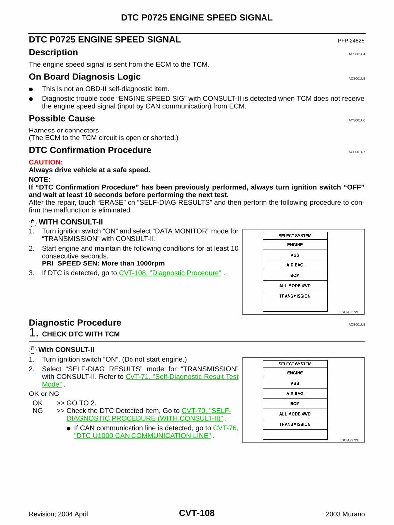
CVT-108
DTC P0725 ENGINE SPEED SIGNAL
Revision; 2004 April 2003 Murano
DTC P0725 ENGINE SPEED SIGNAL PFP:24825
Description ACS001U4
The engine speed signal is sent from the ECM to the TCM.
On Board Diagnosis Logic ACS001U5
This is not an OBD-II self-diagnostic item. Diagnostic trouble code “ENGINE SPEED SIG” with CONSULT-II is detected when TCM does not receive
the engine speed signal (input by CAN communication) from ECM.
Possible Cause ACS001U6
Harness or connectors(The ECM to the TCM circuit is open or shorted.)
DTC Confirmation Procedure ACS001U7
CAUTION:Always drive vehicle at a safe speed.NOTE:If “DTC Confirmation Procedure” has been previously performed, always turn ignition switch “OFF”and wait at least 10 seconds before performing the next test.After the repair, touch “ERASE” on “SELF-DIAG RESULTS” and then perform the following procedure to con-firm the malfunction is eliminated.
WITH CONSULT-II1. Turn ignition switch “ON” and select “DATA MONITOR” mode for
“TRANSMISSION” with CONSULT-II.2. Start engine and maintain the following conditions for at least 10
consecutive seconds.PRI SPEED SEN: More than 1000rpm
3. If DTC is detected, go to CVT-108, "Diagnostic Procedure" .
Diagnostic Procedure ACS001U8
1. CHECK DTC WITH TCM
With CONSULT-II1. Turn ignition switch “ON”. (Do not start engine.)2. Select “SELF-DIAG RESULTS” mode for “TRANSMISSION”
with CONSULT-II. Refer to CVT-71, "Self-Diagnostic Result TestMode" .
OK or NGOK >> GO TO 2.NG >> Check the DTC Detected Item, Go to CVT-70, "SELF-
DIAGNOSTIC PROCEDURE (WITH CONSULT-II)" . If CAN communication line is detected, go to CVT-76,
"DTC U1000 CAN COMMUNICATION LINE" .
SCIA2272E
SCIA2272E
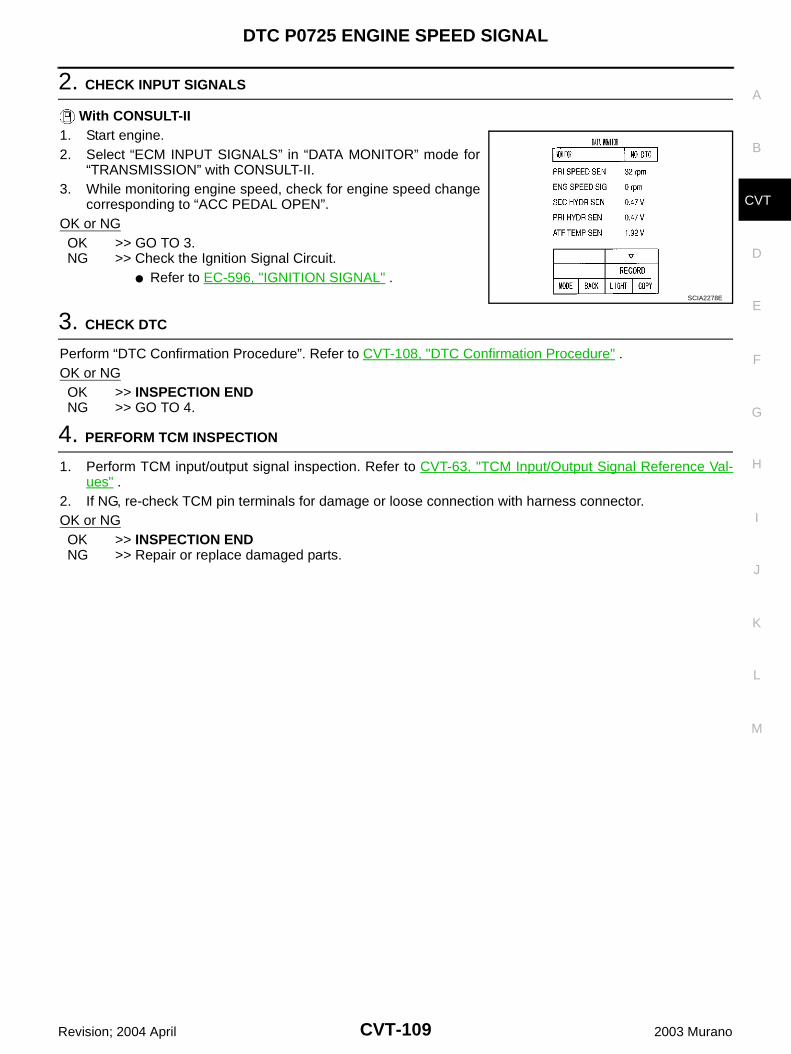
DTC P0725 ENGINE SPEED SIGNAL
CVT-109
D
E
F
G
H
I
J
K
L
M
A
B
CVT
Revision; 2004 April 2003 Murano
2. CHECK INPUT SIGNALS
With CONSULT-II1. Start engine.2. Select “ECM INPUT SIGNALS” in “DATA MONITOR” mode for
“TRANSMISSION” with CONSULT-II.3. While monitoring engine speed, check for engine speed change
corresponding to “ACC PEDAL OPEN”.OK or NGOK >> GO TO 3.NG >> Check the Ignition Signal Circuit.
Refer to EC-596, "IGNITION SIGNAL" .
3. CHECK DTC
Perform “DTC Confirmation Procedure”. Refer to CVT-108, "DTC Confirmation Procedure" .OK or NGOK >> INSPECTION ENDNG >> GO TO 4.
4. PERFORM TCM INSPECTION
1. Perform TCM input/output signal inspection. Refer to CVT-63, "TCM Input/Output Signal Reference Val-ues" .
2. If NG, re-check TCM pin terminals for damage or loose connection with harness connector.OK or NGOK >> INSPECTION ENDNG >> Repair or replace damaged parts.
SCIA2278E
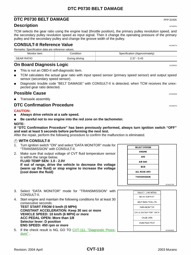
CVT-110
DTC P0730 BELT DAMAGE
Revision; 2004 April 2003 Murano
DTC P0730 BELT DAMAGE PFP:31935
Description ACS002IU
TCM selects the gear ratio using the engine load (throttle position), the primary pulley revolution speed, andthe secondary pulley revolution speed as input signal. Then it change the operating pressure of the primarypulley and the secondary pulley and change the groove width of the pulley.
CONSULT-II Reference Value ACS002T4
Remarks: Specification data are reference values.
On Board Diagnosis Logic ACS002IV
This is not an OBD-II self-diagnostic item. TCM calculates the actual gear ratio with input speed sensor (primary speed sensor) and output speed
sensor (secondary speed sensor). Diagnostic trouble code “BELT DAMAGE” with CONSULT-II is detected, when TCM receives the unex-
pected gear ratio detected.
Possible Cause ACS002IW
Transaxle assembly
DTC Confirmation Procedure ACS002T5
CAUTION: Always drive vehicle at a safe speed. Be careful not to rev engine into the red zone on the tachometer.NOTE:If “DTC Confirmation Procedure” has been previously performed, always turn ignition switch “OFF”and wait at least 5 seconds before performing the next test.After the repair, perform the following procedure to confirm the malfunction is eliminated.
WITH CONSULT-II1. Turn ignition switch “ON” and select “DATA MONITOR” mode for
“TRANSMISSION” with CONSULT-II.2. Make sure that output voltage of CVT fluid temperature sensor
is within the range below.FLUID TEMP SEN: 1.0 - 2.0VIf out of range, drive the vehicle to decrease the voltage(warm up the fluid) or stop engine to increase the voltage(cool down the fluid)
3. Select “DATA MONITOR” mode for “TRANSMISSION” withCONSULT-II.
4. Start engine and maintain the following conditions for at least 30consecutive seconds.TEST START FROM 0 km/h (0 MPH)CONSTANT ACCELERATION: Keep 30 sec or moreVEHICLE SPEED: 10 km/h (6 MPH) or moreACC PEDAL OPEN: More than 1/8Selector lever: D positionENG SPEED: 450 rpm or more
5. If the check result is NG, GO TO CVT-111, "Diagnostic Proce-dure" .
Monitor item Condition Specification (Approximately)
GEAR RATIO During driving 2.37 - 0.43
SCIA2272E
SCIA5492E
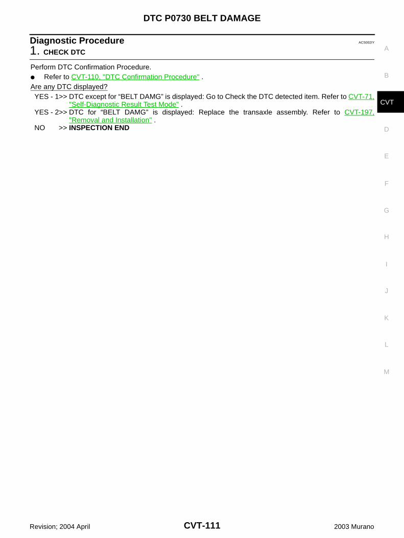
DTC P0730 BELT DAMAGE
CVT-111
D
E
F
G
H
I
J
K
L
M
A
B
CVT
Revision; 2004 April 2003 Murano
Diagnostic Procedure ACS002IY
1. CHECK DTC
Perform DTC Confirmation Procedure. Refer to CVT-110, "DTC Confirmation Procedure" .Are any DTC displayed?YES - 1>> DTC except for “BELT DAMG” is displayed: Go to Check the DTC detected item. Refer to CVT-71,
"Self-Diagnostic Result Test Mode" .YES - 2>> DTC for “BELT DAMG” is displayed: Replace the transaxle assembly. Refer to CVT-197,
"Removal and Installation" . NO >> INSPECTION END
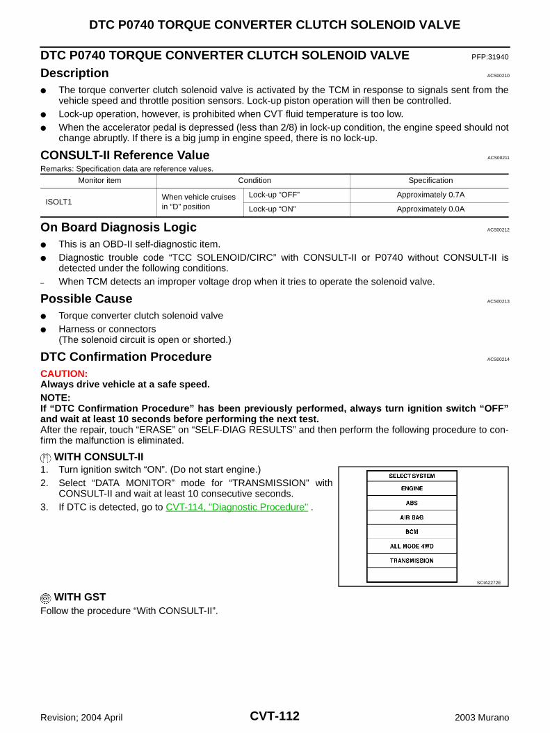
CVT-112
DTC P0740 TORQUE CONVERTER CLUTCH SOLENOID VALVE
Revision; 2004 April 2003 Murano
DTC P0740 TORQUE CONVERTER CLUTCH SOLENOID VALVE PFP:31940
Description ACS00210
The torque converter clutch solenoid valve is activated by the TCM in response to signals sent from thevehicle speed and throttle position sensors. Lock-up piston operation will then be controlled.
Lock-up operation, however, is prohibited when CVT fluid temperature is too low. When the accelerator pedal is depressed (less than 2/8) in lock-up condition, the engine speed should not
change abruptly. If there is a big jump in engine speed, there is no lock-up.
CONSULT-II Reference Value ACS00211
Remarks: Specification data are reference values.
On Board Diagnosis Logic ACS00212
This is an OBD-II self-diagnostic item. Diagnostic trouble code “TCC SOLENOID/CIRC” with CONSULT-II or P0740 without CONSULT-II is
detected under the following conditions.– When TCM detects an improper voltage drop when it tries to operate the solenoid valve.
Possible Cause ACS00213
Torque converter clutch solenoid valve Harness or connectors
(The solenoid circuit is open or shorted.)
DTC Confirmation Procedure ACS00214
CAUTION:Always drive vehicle at a safe speed.NOTE:If “DTC Confirmation Procedure” has been previously performed, always turn ignition switch “OFF”and wait at least 10 seconds before performing the next test.After the repair, touch “ERASE” on “SELF-DIAG RESULTS” and then perform the following procedure to con-firm the malfunction is eliminated.
WITH CONSULT-II1. Turn ignition switch “ON”. (Do not start engine.)2. Select “DATA MONITOR” mode for “TRANSMISSION” with
CONSULT-II and wait at least 10 consecutive seconds.3. If DTC is detected, go to CVT-114, "Diagnostic Procedure" .
WITH GSTFollow the procedure “With CONSULT-II”.
Monitor item Condition Specification
ISOLT1When vehicle cruises in “D” position
Lock-up “OFF” Approximately 0.7A
Lock-up “ON” Approximately 0.0A
SCIA2272E

DTC P0740 TORQUE CONVERTER CLUTCH SOLENOID VALVE
CVT-113
D
E
F
G
H
I
J
K
L
M
A
B
CVT
Revision; 2004 April 2003 Murano
Wiring Diagram - CVT - TCV ACS002T6
TCWA0153E
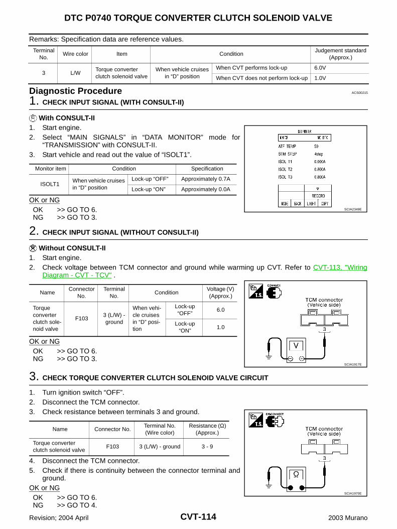
CVT-114
DTC P0740 TORQUE CONVERTER CLUTCH SOLENOID VALVE
Revision; 2004 April 2003 Murano
Remarks: Specification data are reference values.
Diagnostic Procedure ACS00215
1. CHECK INPUT SIGNAL (WITH CONSULT-II)
With CONSULT-II1. Start engine.2. Select “MAIN SIGNALS” in “DATA MONITOR” mode for
“TRANSMISSION” with CONSULT-II.3. Start vehicle and read out the value of “ISOLT1”.
OK or NGOK >> GO TO 6.NG >> GO TO 3.
2. CHECK INPUT SIGNAL (WITHOUT CONSULT-II)
Without CONSULT-II1. Start engine.2. Check voltage between TCM connector and ground while warming up CVT. Refer to CVT-113, "Wiring
Diagram - CVT - TCV" .
OK or NGOK >> GO TO 6.NG >> GO TO 3.
3. CHECK TORQUE CONVERTER CLUTCH SOLENOID VALVE CIRCUIT
1. Turn ignition switch “OFF”.2. Disconnect the TCM connector.3. Check resistance between terminals 3 and ground.
4. Disconnect the TCM connector.5. Check if there is continuity between the connector terminal and
ground.OK or NGOK >> GO TO 6.NG >> GO TO 4.
Terminal No.
Wire color Item ConditionJudgement standard
(Approx.)
3 L/WTorque converter clutch solenoid valve
When vehicle cruises in “D” position
When CVT performs lock-up 6.0V
When CVT does not perform lock-up 1.0V
Monitor item Condition Specification
ISOLT1When vehicle cruises in “D” position
Lock-up “OFF” Approximately 0.7A
Lock-up “ON” Approximately 0.0A
SCIA2349E
NameConnector
No.Terminal
No.Condition
Voltage (V) (Approx.)
Torque converter clutch sole-noid valve
F1033 (L/W) - ground
When vehi-cle cruises in “D” posi-tion
Lock-up “OFF”
6.0
Lock-up “ON”
1.0
SCIA1917E
Name Connector No.Terminal No. (Wire color)
Resistance (Ω) (Approx.)
Torque converter clutch solenoid valve
F103 3 (L/W) - ground 3 - 9
SCIA1970E
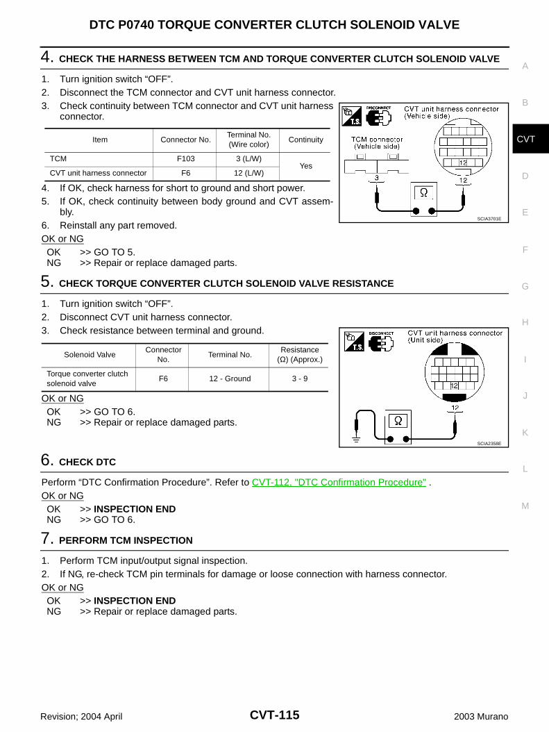
DTC P0740 TORQUE CONVERTER CLUTCH SOLENOID VALVE
CVT-115
D
E
F
G
H
I
J
K
L
M
A
B
CVT
Revision; 2004 April 2003 Murano
4. CHECK THE HARNESS BETWEEN TCM AND TORQUE CONVERTER CLUTCH SOLENOID VALVE
1. Turn ignition switch “OFF”.2. Disconnect the TCM connector and CVT unit harness connector.3. Check continuity between TCM connector and CVT unit harness
connector.
4. If OK, check harness for short to ground and short power.5. If OK, check continuity between body ground and CVT assem-
bly.6. Reinstall any part removed.OK or NGOK >> GO TO 5.NG >> Repair or replace damaged parts.
5. CHECK TORQUE CONVERTER CLUTCH SOLENOID VALVE RESISTANCE
1. Turn ignition switch “OFF”.2. Disconnect CVT unit harness connector.3. Check resistance between terminal and ground.
OK or NGOK >> GO TO 6.NG >> Repair or replace damaged parts.
6. CHECK DTC
Perform “DTC Confirmation Procedure”. Refer to CVT-112, "DTC Confirmation Procedure" .OK or NGOK >> INSPECTION ENDNG >> GO TO 6.
7. PERFORM TCM INSPECTION
1. Perform TCM input/output signal inspection.2. If NG, re-check TCM pin terminals for damage or loose connection with harness connector.OK or NGOK >> INSPECTION ENDNG >> Repair or replace damaged parts.
Item Connector No.Terminal No. (Wire color)
Continuity
TCM F103 3 (L/W)Yes
CVT unit harness connector F6 12 (L/W)
SCIA3701E
Solenoid ValveConnector
No.Terminal No.
Resistance (Ω) (Approx.)
Torque converter clutch solenoid valve
F6 12 - Ground 3 - 9
SCIA2358E
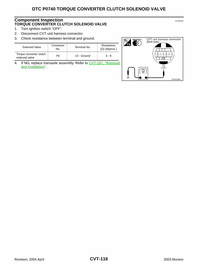
CVT-116
DTC P0740 TORQUE CONVERTER CLUTCH SOLENOID VALVE
Revision; 2004 April 2003 Murano
Component Inspection ACS003KZ
TORQUE CONVERTER CLUTCH SOLENOID VALVE1. Turn ignition switch “OFF”.2. Disconnect CVT unit harness connector.3. Check resistance between terminal and ground.
4. If NG, replace transaxle assembly. Refer to CVT-197, "Removaland Installation" .
Solenoid ValveConnector
No.Terminal No.
Resistance (Ω) (Approx.)
Torque converter clutch solenoid valve
F6 12 - Ground 3 - 9
SCIA2358E
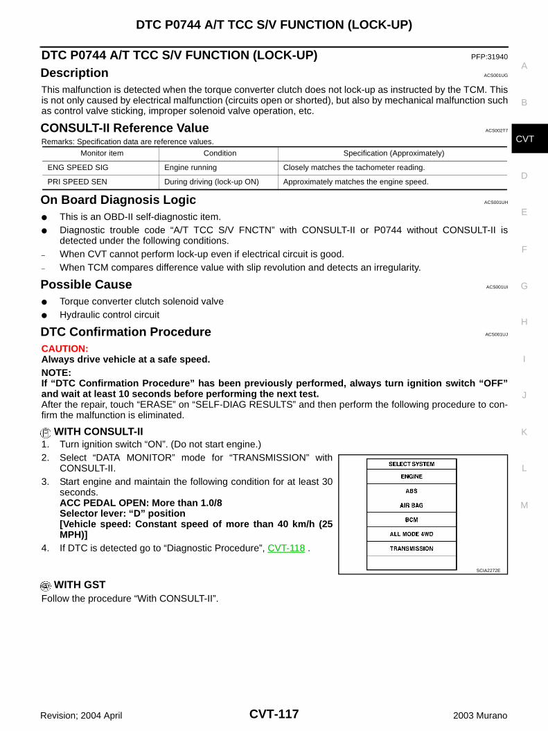
DTC P0744 A/T TCC S/V FUNCTION (LOCK-UP)
CVT-117
D
E
F
G
H
I
J
K
L
M
A
B
CVT
Revision; 2004 April 2003 Murano
DTC P0744 A/T TCC S/V FUNCTION (LOCK-UP) PFP:31940
Description ACS001UG
This malfunction is detected when the torque converter clutch does not lock-up as instructed by the TCM. Thisis not only caused by electrical malfunction (circuits open or shorted), but also by mechanical malfunction suchas control valve sticking, improper solenoid valve operation, etc.
CONSULT-II Reference Value ACS002T7
Remarks: Specification data are reference values.
On Board Diagnosis Logic ACS001UH
This is an OBD-II self-diagnostic item. Diagnostic trouble code “A/T TCC S/V FNCTN” with CONSULT-II or P0744 without CONSULT-II is
detected under the following conditions.– When CVT cannot perform lock-up even if electrical circuit is good.– When TCM compares difference value with slip revolution and detects an irregularity.
Possible Cause ACS001UI
Torque converter clutch solenoid valve Hydraulic control circuit
DTC Confirmation Procedure ACS001UJ
CAUTION:Always drive vehicle at a safe speed.NOTE:If “DTC Confirmation Procedure” has been previously performed, always turn ignition switch “OFF”and wait at least 10 seconds before performing the next test.After the repair, touch “ERASE” on “SELF-DIAG RESULTS” and then perform the following procedure to con-firm the malfunction is eliminated.
WITH CONSULT-II1. Turn ignition switch “ON”. (Do not start engine.)2. Select “DATA MONITOR” mode for “TRANSMISSION” with
CONSULT-II.3. Start engine and maintain the following condition for at least 30
seconds.ACC PEDAL OPEN: More than 1.0/8Selector lever: “D” position [Vehicle speed: Constant speed of more than 40 km/h (25MPH)]
4. If DTC is detected go to “Diagnostic Procedure”, CVT-118 .
WITH GSTFollow the procedure “With CONSULT-II”.
Monitor item Condition Specification (Approximately)
ENG SPEED SIG Engine running Closely matches the tachometer reading.
PRI SPEED SEN During driving (lock-up ON) Approximately matches the engine speed.
SCIA2272E
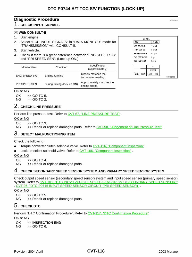
CVT-118
DTC P0744 A/T TCC S/V FUNCTION (LOCK-UP)
Revision; 2004 April 2003 Murano
Diagnostic Procedure ACS001UL
1. CHECK INPUT SIGNALS
With CONSULT-II1. Start engine.2. Select “ECU INPUT SIGNALS” in “DATA MONITOR” mode for
“TRANSMISSION” with CONSULT-II.3. Start vehicle.4. Check if there is a great difference between “ENG SPEED SIG”
and “PRI SPEED SEN”. (Lock-up ON.)
OK or NGOK >> GO TO 5.NG >> GO TO 2.
2. CHECK LINE PRESSURE
Perform line pressure test. Refer to CVT-57, "LINE PRESSURE TEST" .OK or NGOK >> GO TO 3.NG >> Repair or replace damaged parts. Refer to CVT-58, "Judgement of Line Pressure Test" .
3. DETECT MALFUNCTIONING ITEM
Check the following: Torque converter clutch solenoid valve. Refer to CVT-116, "Component Inspection" . Lock-up select solenoid valve. Refer to CVT-166, "Component Inspection" .OK or NGOK >> GO TO 4.NG >> Repair or replace damaged parts.
4. CHECK SECONDARY SPEED SENSOR SYSTEM AND PRIMARY SPEED SENSOR SYSTEM
Check output speed sensor (secondary speed sensor) system and input speed sensor (primary speed sensor)system. Refer to CVT-101, "DTC P0720 VEHICLE SPEED SENSOR CVT (SECONDARY SPEED SENSOR)", CVT-95, "DTC P0715 INPUT SPEED SENSOR CIRCUIT (PRI SPEED SENSOR)" .OK or NGOK >> GO TO 5.NG >> Repair or replace damaged parts.
5. CHECK DTC
Perform “DTC Confirmation Procedure”. Refer to CVT-117, "DTC Confirmation Procedure" .OK or NGOK >> INSPECTION ENDNG >> GO TO 6.
Monitor item ConditionSpecification
(Approximately)
ENG SPEED SIG Engine runningClosely matches the tachometer reading.
PRI SPEED SEN During driving (lock-up ON)Approximately matches the engine speed.
SCIA2279E
DTC P0744 A/T TCC S/V FUNCTION (LOCK-UP)
CVT-119
D
E
F
G
H
I
J
K
L
M
A
B
CVT
Revision; 2004 April 2003 Murano
6. PERFORM TCM INSPECTION
1. Perform TCM input/output signal inspection.2. If NG, re-check TCM pin terminals for damage or loose connection with harness connector.OK or NGOK >> INSPECTION ENDNG >> 1. Repair or replace damaged parts.
2. Replace the transaxle assembly. Refer to CVT-197, "Removal and Installation" .
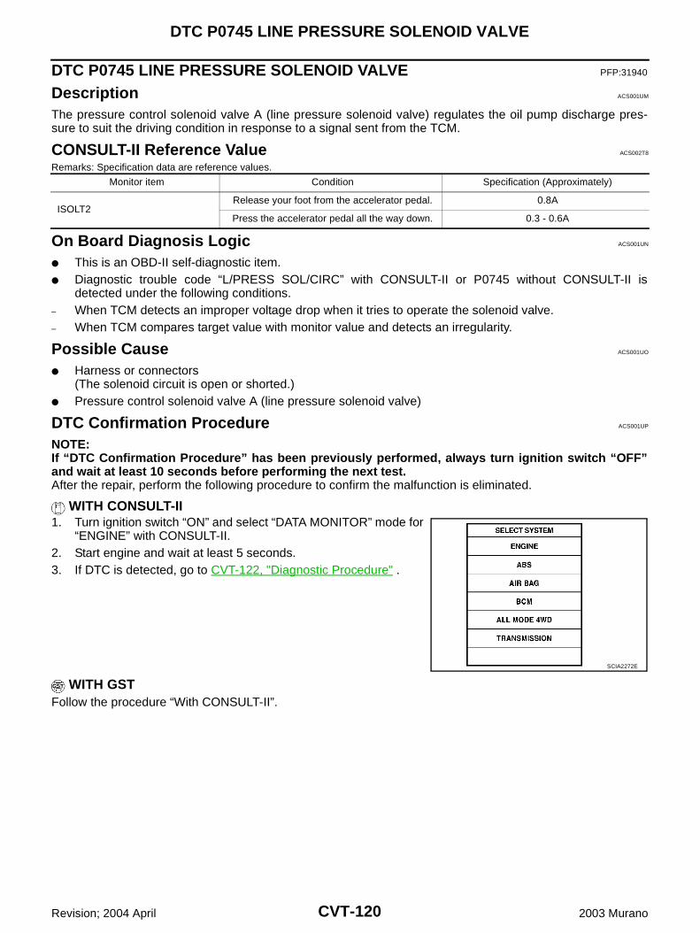
CVT-120
DTC P0745 LINE PRESSURE SOLENOID VALVE
Revision; 2004 April 2003 Murano
DTC P0745 LINE PRESSURE SOLENOID VALVE PFP:31940
Description ACS001UM
The pressure control solenoid valve A (line pressure solenoid valve) regulates the oil pump discharge pres-sure to suit the driving condition in response to a signal sent from the TCM.
CONSULT-II Reference Value ACS002T8
Remarks: Specification data are reference values.
On Board Diagnosis Logic ACS001UN
This is an OBD-II self-diagnostic item. Diagnostic trouble code “L/PRESS SOL/CIRC” with CONSULT-II or P0745 without CONSULT-II is
detected under the following conditions.– When TCM detects an improper voltage drop when it tries to operate the solenoid valve.– When TCM compares target value with monitor value and detects an irregularity.
Possible Cause ACS001UO
Harness or connectors(The solenoid circuit is open or shorted.)
Pressure control solenoid valve A (line pressure solenoid valve)
DTC Confirmation Procedure ACS001UP
NOTE:If “DTC Confirmation Procedure” has been previously performed, always turn ignition switch “OFF”and wait at least 10 seconds before performing the next test.After the repair, perform the following procedure to confirm the malfunction is eliminated.
WITH CONSULT-II1. Turn ignition switch “ON” and select “DATA MONITOR” mode for
“ENGINE” with CONSULT-II.2. Start engine and wait at least 5 seconds.3. If DTC is detected, go to CVT-122, "Diagnostic Procedure" .
WITH GSTFollow the procedure “With CONSULT-II”.
Monitor item Condition Specification (Approximately)
ISOLT2Release your foot from the accelerator pedal. 0.8A
Press the accelerator pedal all the way down. 0.3 - 0.6A
SCIA2272E
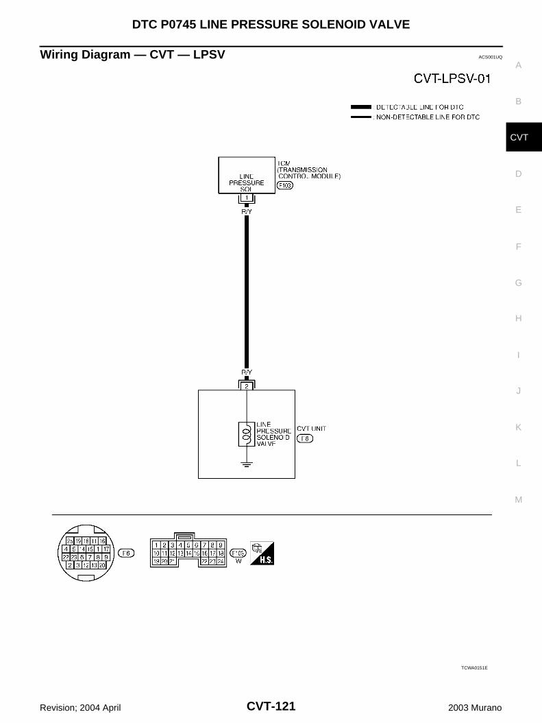
DTC P0745 LINE PRESSURE SOLENOID VALVE
CVT-121
D
E
F
G
H
I
J
K
L
M
A
B
CVT
Revision; 2004 April 2003 Murano
Wiring Diagram — CVT — LPSV ACS001UQ
TCWA0151E
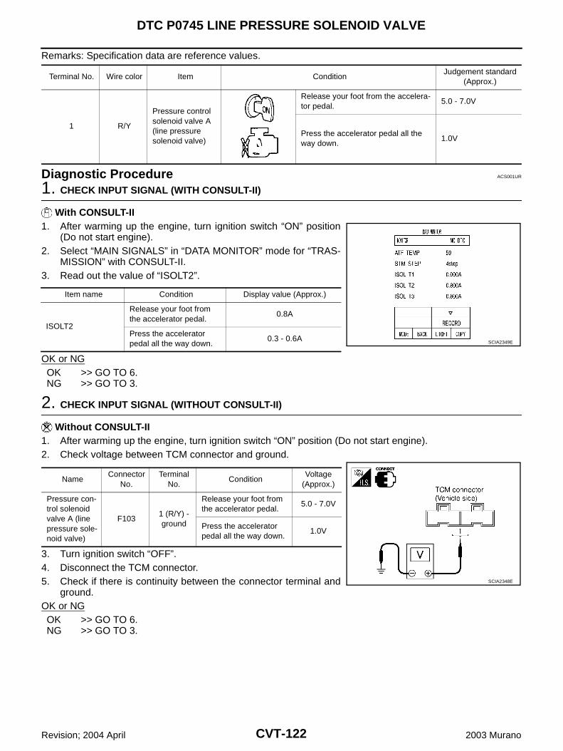
CVT-122
DTC P0745 LINE PRESSURE SOLENOID VALVE
Revision; 2004 April 2003 Murano
Remarks: Specification data are reference values.
Diagnostic Procedure ACS001UR
1. CHECK INPUT SIGNAL (WITH CONSULT-II)
With CONSULT-II1. After warming up the engine, turn ignition switch “ON” position
(Do not start engine).2. Select “MAIN SIGNALS” in “DATA MONITOR” mode for “TRAS-
MISSION” with CONSULT-II.3. Read out the value of “ISOLT2”.
OK or NGOK >> GO TO 6.NG >> GO TO 3.
2. CHECK INPUT SIGNAL (WITHOUT CONSULT-II)
Without CONSULT-II1. After warming up the engine, turn ignition switch “ON” position (Do not start engine).2. Check voltage between TCM connector and ground.
3. Turn ignition switch “OFF”.4. Disconnect the TCM connector.5. Check if there is continuity between the connector terminal and
ground.OK or NGOK >> GO TO 6.NG >> GO TO 3.
Terminal No. Wire color Item ConditionJudgement standard
(Approx.)
1 R/Y
Pressure control solenoid valve A (line pressure solenoid valve)
Release your foot from the accelera-tor pedal.
5.0 - 7.0V
Press the accelerator pedal all the way down.
1.0V
Item name Condition Display value (Approx.)
ISOLT2
Release your foot from the accelerator pedal.
0.8A
Press the accelerator pedal all the way down.
0.3 - 0.6A SCIA2349E
NameConnector
No.Terminal
No.Condition
Voltage (Approx.)
Pressure con-trol solenoid valve A (line pressure sole-noid valve)
F1031 (R/Y) - ground
Release your foot from the accelerator pedal.
5.0 - 7.0V
Press the accelerator pedal all the way down.
1.0V
SCIA2348E
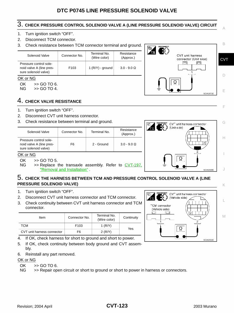
DTC P0745 LINE PRESSURE SOLENOID VALVE
CVT-123
D
E
F
G
H
I
J
K
L
M
A
B
CVT
Revision; 2004 April 2003 Murano
3. CHECK PRESSURE CONTROL SOLENOID VALVE A (LINE PRESSURE SOLENOID VALVE) CIRCUIT
1. Turn ignition switch “OFF”.2. Disconnect TCM connector.3. Check resistance between TCM connector terminal and ground.
OK or NGOK >> GO TO 6.NG >> GO TO 4.
4. CHECK VALVE RESISTANCE
1. Turn ignition switch “OFF”.2. Disconnect CVT unit harness connector.3. Check resistance between terminal and ground.
OK or NGOK >> GO TO 5.NG >> Replace the transaxle assembly. Refer to CVT-197,
"Removal and Installation" .
5. CHECK THE HARNESS BETWEEN TCM AND PRESSURE CONTROL SOLENOID VALVE A (LINE PRESSURE SOLENOID VALVE)
1. Turn ignition switch “OFF”.2. Disconnect CVT unit harness connector and TCM connector.3. Check continuity between CVT unit harness connector and TCM
connector.
4. If OK, check harness for short to ground and short to power.5. If OK, check continuity between body ground and CVT assem-
bly.6. Reinstall any part removed.OK or NGOK >> GO TO 6.NG >> Repair open circuit or short to ground or short to power in harness or connectors.
Solenoid Valve Connector No.Terminal No. (Wire color)
Resistance (Approx.)
Pressure control sole-noid valve A (line pres-sure solenoid valve)
F103 1 (R/Y) - ground 3.0 - 9.0 Ω
SCIA1971E
Solenoid Valve Connector No. Terminal No.Resistance (Approx.)
Pressure control sole-noid valve A (line pres-sure solenoid valve)
F6 2 - Ground 3.0 - 9.0 Ω
SCIA2030E
Item Connector No.Terminal No. (Wire color)
Continuity
TCM F103 1 (R/Y)Yes
CVT unit harness connector F6 2 (R/Y)
SCIA2031E
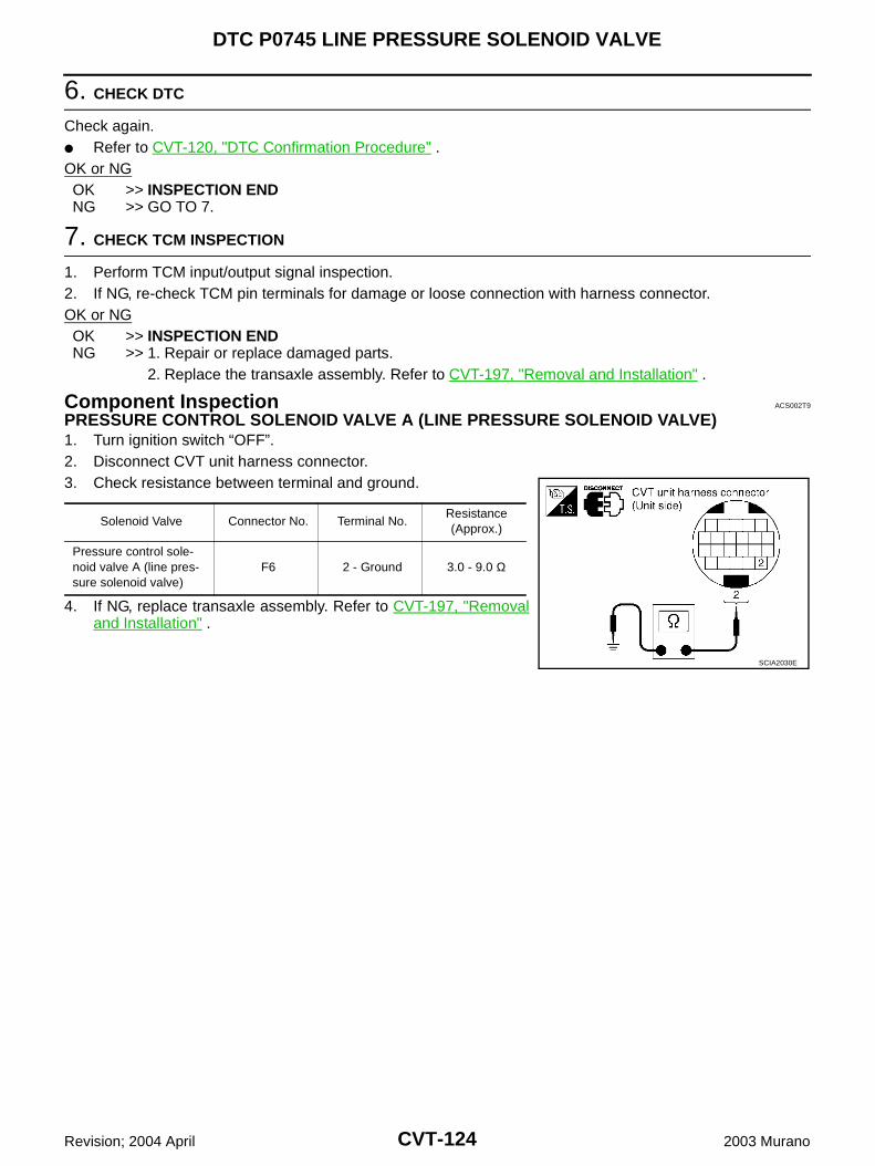
CVT-124
DTC P0745 LINE PRESSURE SOLENOID VALVE
Revision; 2004 April 2003 Murano
6. CHECK DTC
Check again. Refer to CVT-120, "DTC Confirmation Procedure" .OK or NGOK >> INSPECTION ENDNG >> GO TO 7.
7. CHECK TCM INSPECTION
1. Perform TCM input/output signal inspection.2. If NG, re-check TCM pin terminals for damage or loose connection with harness connector.OK or NGOK >> INSPECTION ENDNG >> 1. Repair or replace damaged parts.
2. Replace the transaxle assembly. Refer to CVT-197, "Removal and Installation" .
Component Inspection ACS002T9
PRESSURE CONTROL SOLENOID VALVE A (LINE PRESSURE SOLENOID VALVE)1. Turn ignition switch “OFF”.2. Disconnect CVT unit harness connector.3. Check resistance between terminal and ground.
4. If NG, replace transaxle assembly. Refer to CVT-197, "Removaland Installation" .
Solenoid Valve Connector No. Terminal No.Resistance (Approx.)
Pressure control sole-noid valve A (line pres-sure solenoid valve)
F6 2 - Ground 3.0 - 9.0 Ω
SCIA2030E
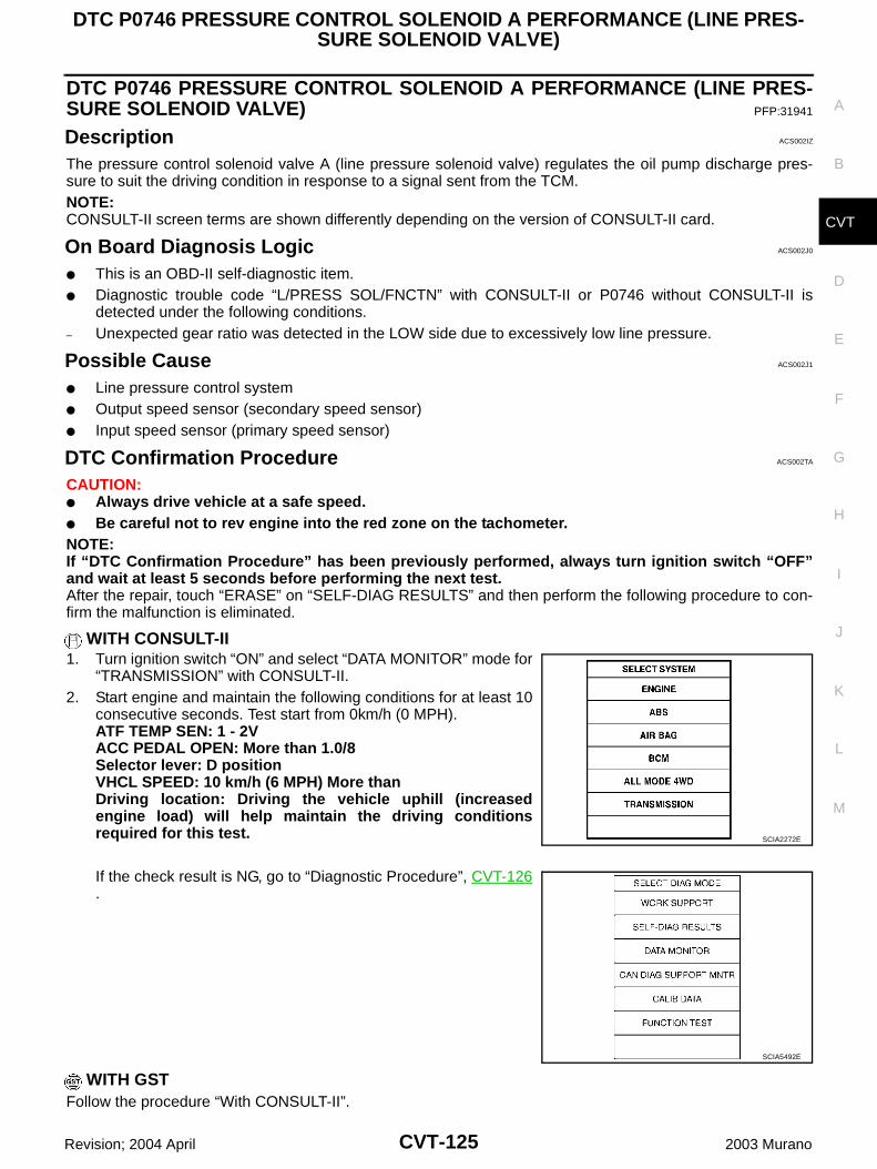
DTC P0746 PRESSURE CONTROL SOLENOID A PERFORMANCE (LINE PRES-SURE SOLENOID VALVE)
CVT-125
D
E
F
G
H
I
J
K
L
M
A
B
CVT
Revision; 2004 April 2003 Murano
DTC P0746 PRESSURE CONTROL SOLENOID A PERFORMANCE (LINE PRES-SURE SOLENOID VALVE) PFP:31941
Description ACS002IZ
The pressure control solenoid valve A (line pressure solenoid valve) regulates the oil pump discharge pres-sure to suit the driving condition in response to a signal sent from the TCM.NOTE:CONSULT-II screen terms are shown differently depending on the version of CONSULT-II card.
On Board Diagnosis Logic ACS002J0
This is an OBD-II self-diagnostic item. Diagnostic trouble code “L/PRESS SOL/FNCTN” with CONSULT-II or P0746 without CONSULT-II is
detected under the following conditions.– Unexpected gear ratio was detected in the LOW side due to excessively low line pressure.
Possible Cause ACS002J1
Line pressure control system Output speed sensor (secondary speed sensor) Input speed sensor (primary speed sensor)
DTC Confirmation Procedure ACS002TA
CAUTION: Always drive vehicle at a safe speed. Be careful not to rev engine into the red zone on the tachometer.NOTE:If “DTC Confirmation Procedure” has been previously performed, always turn ignition switch “OFF”and wait at least 5 seconds before performing the next test.After the repair, touch “ERASE” on “SELF-DIAG RESULTS” and then perform the following procedure to con-firm the malfunction is eliminated.
WITH CONSULT-II1. Turn ignition switch “ON” and select “DATA MONITOR” mode for
“TRANSMISSION” with CONSULT-II.2. Start engine and maintain the following conditions for at least 10
consecutive seconds. Test start from 0km/h (0 MPH).ATF TEMP SEN: 1 - 2VACC PEDAL OPEN: More than 1.0/8Selector lever: D positionVHCL SPEED: 10 km/h (6 MPH) More thanDriving location: Driving the vehicle uphill (increasedengine load) will help maintain the driving conditionsrequired for this test.
If the check result is NG, go to “Diagnostic Procedure”, CVT-126.
WITH GSTFollow the procedure “With CONSULT-II”.
SCIA2272E
SCIA5492E
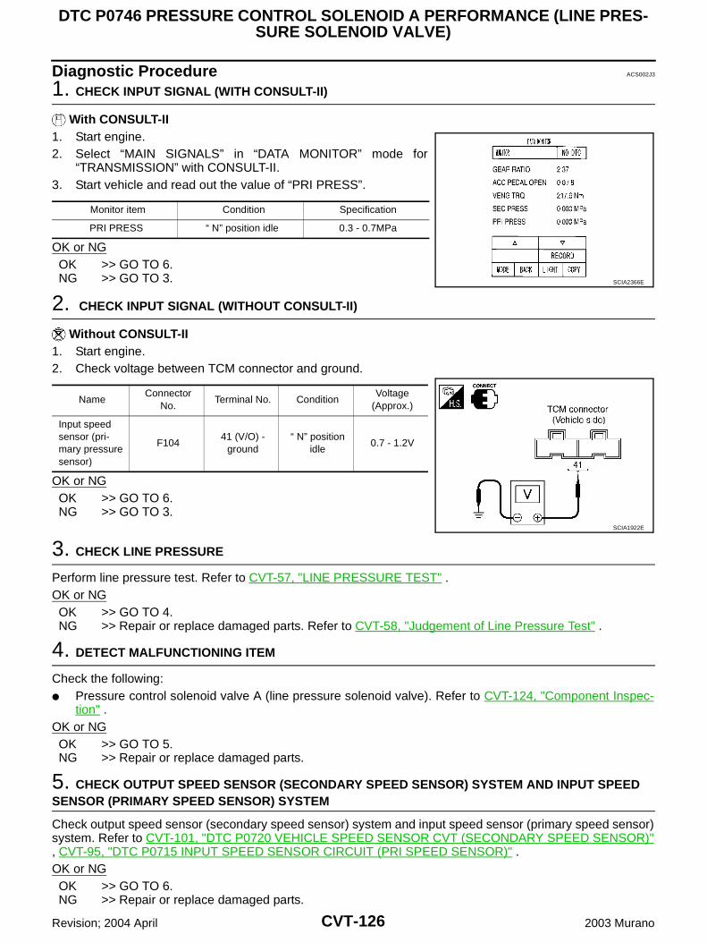
CVT-126
DTC P0746 PRESSURE CONTROL SOLENOID A PERFORMANCE (LINE PRES-SURE SOLENOID VALVE)
Revision; 2004 April 2003 Murano
Diagnostic Procedure ACS002J3
1. CHECK INPUT SIGNAL (WITH CONSULT-II)
With CONSULT-II1. Start engine.2. Select “MAIN SIGNALS” in “DATA MONITOR” mode for
“TRANSMISSION” with CONSULT-II.3. Start vehicle and read out the value of “PRI PRESS”.
OK or NGOK >> GO TO 6.NG >> GO TO 3.
2. CHECK INPUT SIGNAL (WITHOUT CONSULT-II)
Without CONSULT-II1. Start engine.2. Check voltage between TCM connector and ground.
OK or NGOK >> GO TO 6.NG >> GO TO 3.
3. CHECK LINE PRESSURE
Perform line pressure test. Refer to CVT-57, "LINE PRESSURE TEST" .OK or NGOK >> GO TO 4.NG >> Repair or replace damaged parts. Refer to CVT-58, "Judgement of Line Pressure Test" .
4. DETECT MALFUNCTIONING ITEM
Check the following: Pressure control solenoid valve A (line pressure solenoid valve). Refer to CVT-124, "Component Inspec-
tion" .OK or NGOK >> GO TO 5.NG >> Repair or replace damaged parts.
5. CHECK OUTPUT SPEED SENSOR (SECONDARY SPEED SENSOR) SYSTEM AND INPUT SPEED SENSOR (PRIMARY SPEED SENSOR) SYSTEM
Check output speed sensor (secondary speed sensor) system and input speed sensor (primary speed sensor)system. Refer to CVT-101, "DTC P0720 VEHICLE SPEED SENSOR CVT (SECONDARY SPEED SENSOR)", CVT-95, "DTC P0715 INPUT SPEED SENSOR CIRCUIT (PRI SPEED SENSOR)" .OK or NGOK >> GO TO 6.NG >> Repair or replace damaged parts.
Monitor item Condition Specification
PRI PRESS “ N” position idle 0.3 - 0.7MPa
SCIA2366E
NameConnector
No.Terminal No. Condition
Voltage (Approx.)
Input speed sensor (pri-mary pressure sensor)
F10441 (V/O) -
ground“ N” position
idle0.7 - 1.2V
SCIA1922E
DTC P0746 PRESSURE CONTROL SOLENOID A PERFORMANCE (LINE PRES-SURE SOLENOID VALVE)
CVT-127
D
E
F
G
H
I
J
K
L
M
A
B
CVT
Revision; 2004 April 2003 Murano
6. DETECT MALFUNCTIONING ITEM
Check the following: Power supply and ground circuit for TCM. The TCM pin terminals for damage or loose connection with harness connector.OK or NGOK >> GO TO 7.NG >> Repair or replace damaged parts.
7. CHECK DTC
Perform DTC Confirmation Procedure. Refer to CVT-125, "DTC Confirmation Procedure" .OK or NGOK >> INSPECTION ENDNG >> Replace the transaxle assembly or TCM. Refer to CVT-197, "Removal and Installation" .
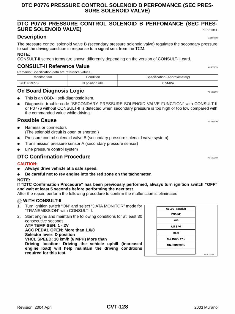
CVT-128
DTC P0776 PRESSURE CONTROL SOLENOID B PERFOMANCE (SEC PRES-SURE SOLENOID VALVE)
Revision; 2004 April 2003 Murano
DTC P0776 PRESSURE CONTROL SOLENOID B PERFOMANCE (SEC PRES-SURE SOLENOID VALVE) PFP:31941
Description ACS002J4
The pressure control solenoid valve B (secondary pressure solenoid valve) regulates the secondary pressureto suit the driving condition in response to a signal sent from the TCM.NOTE:CONSULT-II screen terms are shown differently depending on the version of CONSULT-II card.
CONSULT-II Reference Value ACS002TB
Remarks: Specification data are reference values.
On Board Diagnosis Logic ACS002TC
This is an OBD-II self-diagnostic item. Diagnostic trouble code “SECONDARY PRESSURE SOLENOID VALVE FUNCTION” with CONSULT-II
or P0776 without CONSULT-II is detected when secondary pressure is too high or too low compared withthe commanded value while driving.
Possible Cause ACS002J6
Harness or connectors(The solenoid circuit is open or shorted.)
Pressure control solenoid valve B (secondary pressure solenoid valve system) Transmission pressure sensor A (secondary pressure sensor) Line pressure control system
DTC Confirmation Procedure ACS002TD
CAUTION: Always drive vehicle at a safe speed. Be careful not to rev engine into the red zone on the tachometer.NOTE:If “DTC Confirmation Procedure” has been previously performed, always turn ignition switch “OFF”and wait at least 5 seconds before performing the next test.After the repair, perform the following procedure to confirm the malfunction is eliminated.
WITH CONSULT-II1. Turn ignition switch “ON” and select “DATA MONITOR” mode for
“TRANSMISSION” with CONSULT-II.2. Start engine and maintain the following conditions for at least 30
consecutive seconds.ATF TEMP SEN: 1 - 2VACC PEDAL OPEN: More than 1.0/8Selector lever: D positionVHCL SPEED: 10 km/h (6 MPH) More thanDriving location: Driving the vehicle uphill (increasedengine load) will help maintain the driving conditionsrequired for this test.
Monitor item Condition Specification (Approximately)
SEC PRESS N position idle 0.5MPa
SCIA2272E
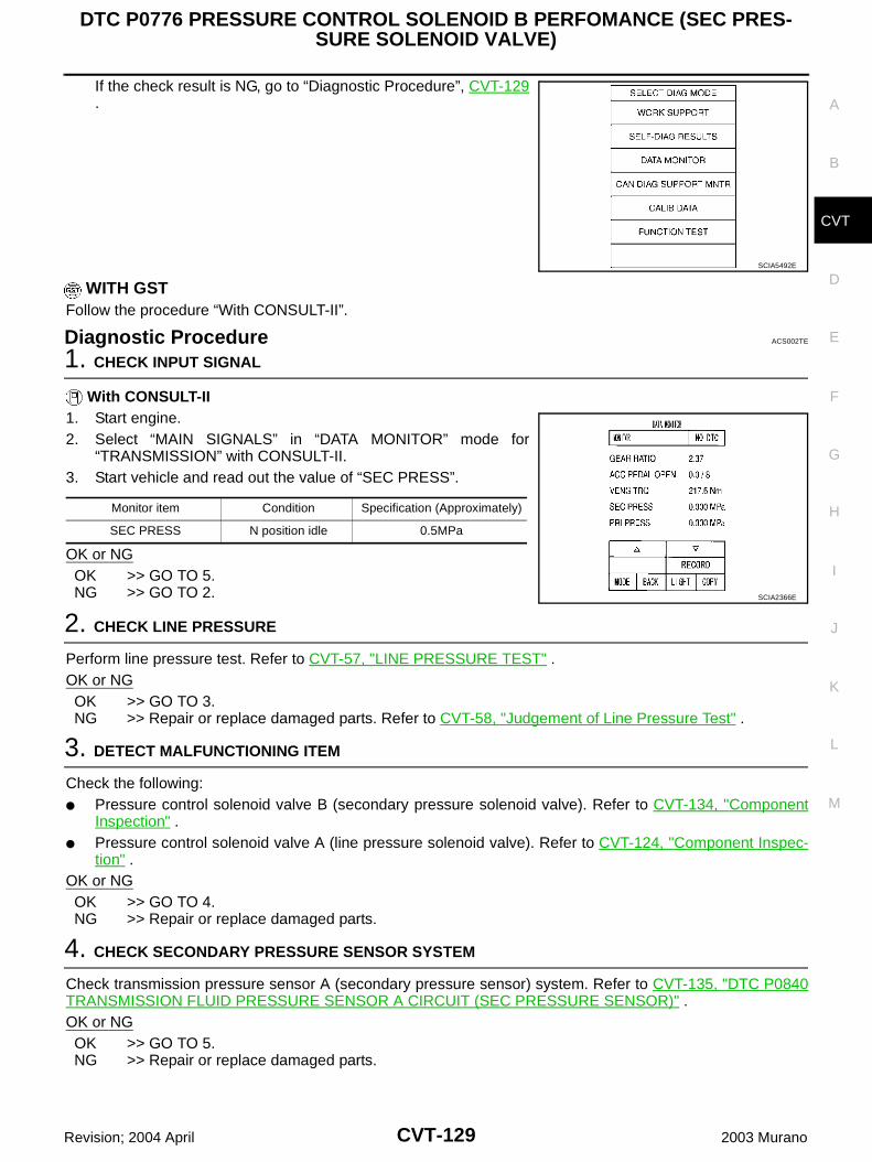
DTC P0776 PRESSURE CONTROL SOLENOID B PERFOMANCE (SEC PRES-SURE SOLENOID VALVE)
CVT-129
D
E
F
G
H
I
J
K
L
M
A
B
CVT
Revision; 2004 April 2003 Murano
If the check result is NG, go to “Diagnostic Procedure”, CVT-129.
WITH GSTFollow the procedure “With CONSULT-II”.
Diagnostic Procedure ACS002TE
1. CHECK INPUT SIGNAL
With CONSULT-II1. Start engine.2. Select “MAIN SIGNALS” in “DATA MONITOR” mode for
“TRANSMISSION” with CONSULT-II.3. Start vehicle and read out the value of “SEC PRESS”.
OK or NGOK >> GO TO 5.NG >> GO TO 2.
2. CHECK LINE PRESSURE
Perform line pressure test. Refer to CVT-57, "LINE PRESSURE TEST" .OK or NGOK >> GO TO 3.NG >> Repair or replace damaged parts. Refer to CVT-58, "Judgement of Line Pressure Test" .
3. DETECT MALFUNCTIONING ITEM
Check the following: Pressure control solenoid valve B (secondary pressure solenoid valve). Refer to CVT-134, "Component
Inspection" . Pressure control solenoid valve A (line pressure solenoid valve). Refer to CVT-124, "Component Inspec-
tion" .OK or NGOK >> GO TO 4.NG >> Repair or replace damaged parts.
4. CHECK SECONDARY PRESSURE SENSOR SYSTEM
Check transmission pressure sensor A (secondary pressure sensor) system. Refer to CVT-135, "DTC P0840TRANSMISSION FLUID PRESSURE SENSOR A CIRCUIT (SEC PRESSURE SENSOR)" .OK or NGOK >> GO TO 5.NG >> Repair or replace damaged parts.
SCIA5492E
Monitor item Condition Specification (Approximately)
SEC PRESS N position idle 0.5MPa
SCIA2366E
CVT-130
DTC P0776 PRESSURE CONTROL SOLENOID B PERFOMANCE (SEC PRES-SURE SOLENOID VALVE)
Revision; 2004 April 2003 Murano
5. DETECT MALFUNCTIONING ITEM
Check the following: Power supply and ground circuit for TCM. The TCM pin terminals for damage or loose connection with harness connector.OK or NGOK >> GO TO 6.NG >> Repair or replace damaged parts.
6. CHECK DTC
Perform DTC Confirmation Procedure. Refer to CVT-128, "DTC Confirmation Procedure" .OK or NGOK >> INSPECTION ENDNG >> Replace the transaxle assembly. Refer to CVT-197, "Removal and Installation" .
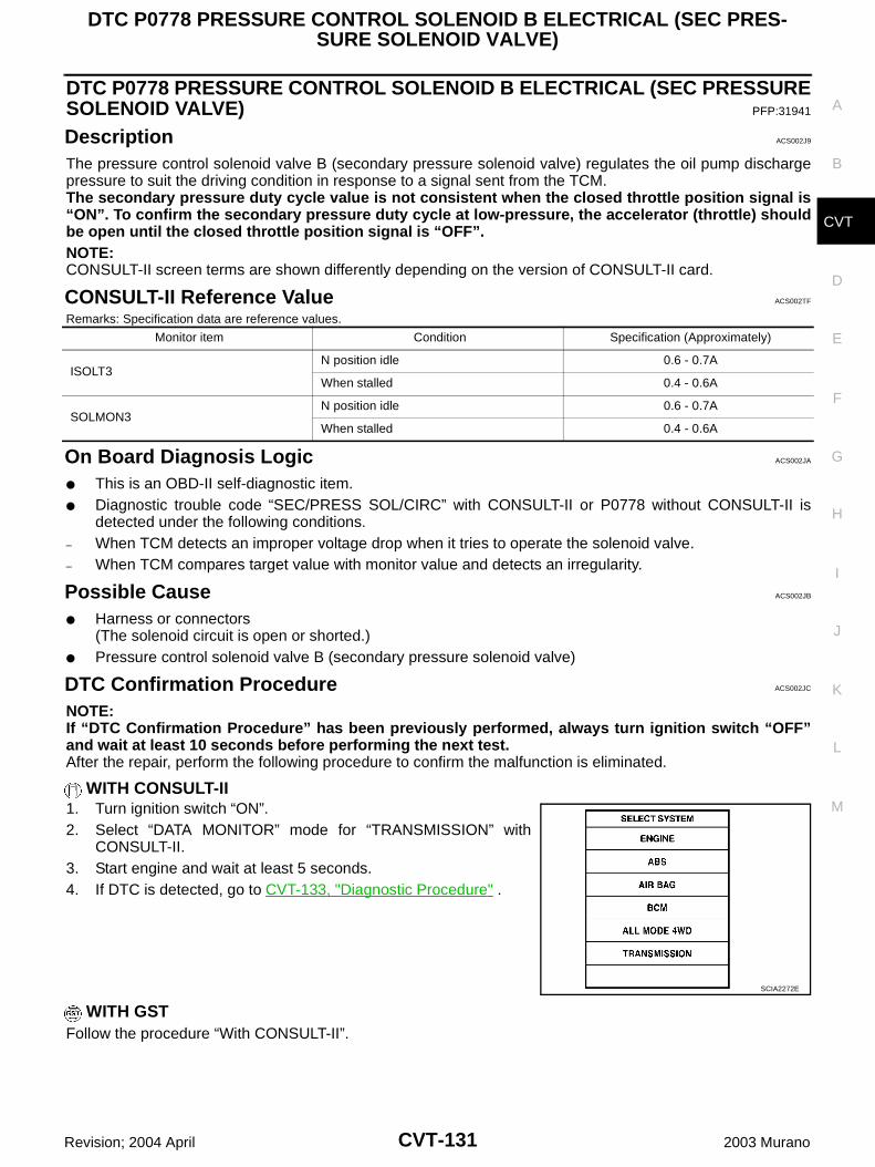
DTC P0778 PRESSURE CONTROL SOLENOID B ELECTRICAL (SEC PRES-SURE SOLENOID VALVE)
CVT-131
D
E
F
G
H
I
J
K
L
M
A
B
CVT
Revision; 2004 April 2003 Murano
DTC P0778 PRESSURE CONTROL SOLENOID B ELECTRICAL (SEC PRESSURESOLENOID VALVE) PFP:31941
Description ACS002J9
The pressure control solenoid valve B (secondary pressure solenoid valve) regulates the oil pump dischargepressure to suit the driving condition in response to a signal sent from the TCM.The secondary pressure duty cycle value is not consistent when the closed throttle position signal is“ON”. To confirm the secondary pressure duty cycle at low-pressure, the accelerator (throttle) shouldbe open until the closed throttle position signal is “OFF”.NOTE:CONSULT-II screen terms are shown differently depending on the version of CONSULT-II card.
CONSULT-II Reference Value ACS002TF
Remarks: Specification data are reference values.
On Board Diagnosis Logic ACS002JA
This is an OBD-II self-diagnostic item. Diagnostic trouble code “SEC/PRESS SOL/CIRC” with CONSULT-II or P0778 without CONSULT-II is
detected under the following conditions.– When TCM detects an improper voltage drop when it tries to operate the solenoid valve.– When TCM compares target value with monitor value and detects an irregularity.
Possible Cause ACS002JB
Harness or connectors(The solenoid circuit is open or shorted.)
Pressure control solenoid valve B (secondary pressure solenoid valve)
DTC Confirmation Procedure ACS002JC
NOTE:If “DTC Confirmation Procedure” has been previously performed, always turn ignition switch “OFF”and wait at least 10 seconds before performing the next test.After the repair, perform the following procedure to confirm the malfunction is eliminated.
WITH CONSULT-II1. Turn ignition switch “ON”.2. Select “DATA MONITOR” mode for “TRANSMISSION” with
CONSULT-II.3. Start engine and wait at least 5 seconds.4. If DTC is detected, go to CVT-133, "Diagnostic Procedure" .
WITH GSTFollow the procedure “With CONSULT-II”.
Monitor item Condition Specification (Approximately)
ISOLT3N position idle 0.6 - 0.7A
When stalled 0.4 - 0.6A
SOLMON3N position idle 0.6 - 0.7A
When stalled 0.4 - 0.6A
SCIA2272E
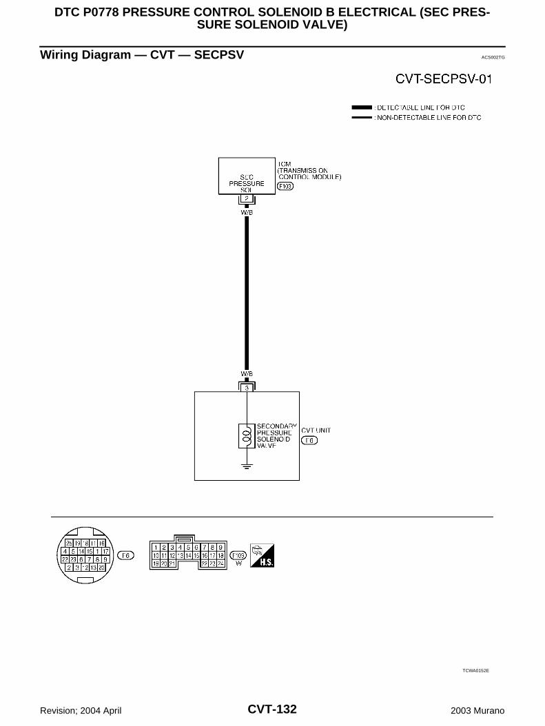
CVT-132
DTC P0778 PRESSURE CONTROL SOLENOID B ELECTRICAL (SEC PRES-SURE SOLENOID VALVE)
Revision; 2004 April 2003 Murano
Wiring Diagram — CVT — SECPSV ACS002TG
TCWA0152E
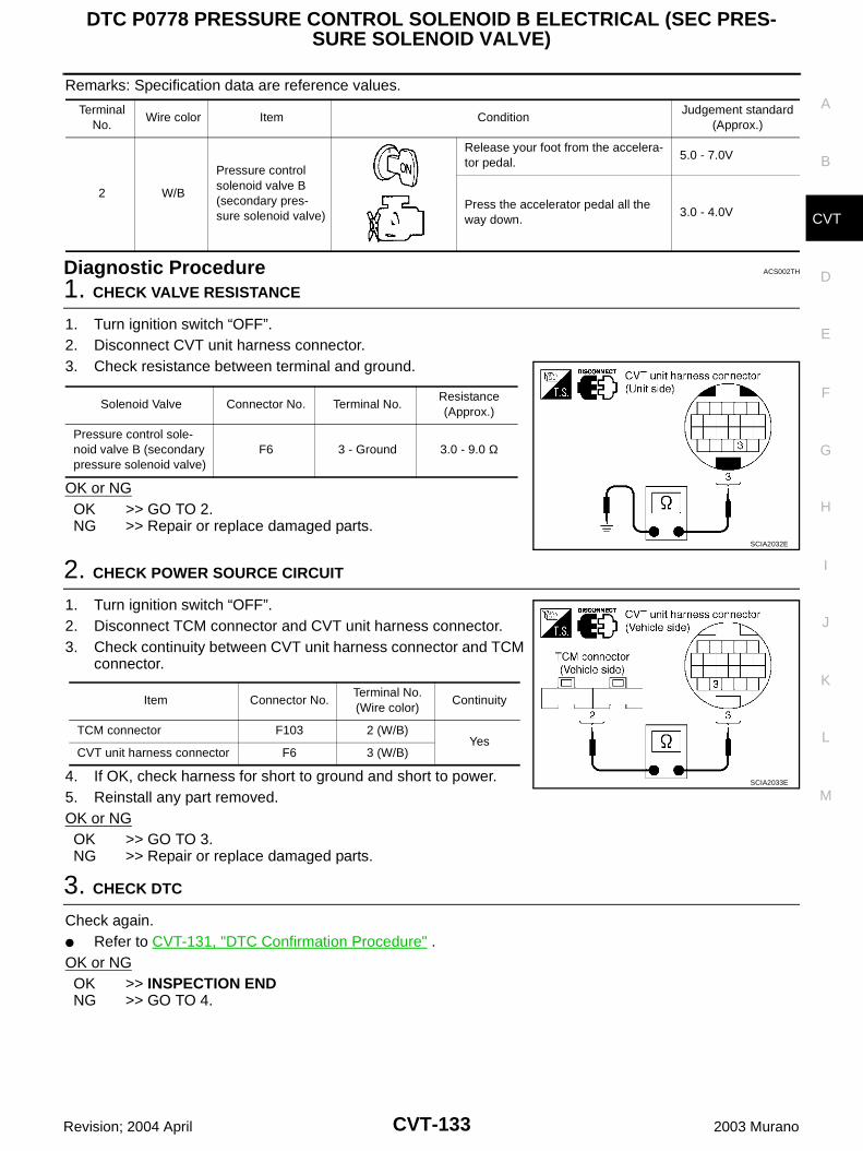
DTC P0778 PRESSURE CONTROL SOLENOID B ELECTRICAL (SEC PRES-SURE SOLENOID VALVE)
CVT-133
D
E
F
G
H
I
J
K
L
M
A
B
CVT
Revision; 2004 April 2003 Murano
Remarks: Specification data are reference values.
Diagnostic Procedure ACS002TH
1. CHECK VALVE RESISTANCE
1. Turn ignition switch “OFF”.2. Disconnect CVT unit harness connector.3. Check resistance between terminal and ground.
OK or NGOK >> GO TO 2.NG >> Repair or replace damaged parts.
2. CHECK POWER SOURCE CIRCUIT
1. Turn ignition switch “OFF”.2. Disconnect TCM connector and CVT unit harness connector.3. Check continuity between CVT unit harness connector and TCM
connector.
4. If OK, check harness for short to ground and short to power.5. Reinstall any part removed.OK or NGOK >> GO TO 3.NG >> Repair or replace damaged parts.
3. CHECK DTC
Check again. Refer to CVT-131, "DTC Confirmation Procedure" .OK or NGOK >> INSPECTION ENDNG >> GO TO 4.
Terminal No.
Wire color Item ConditionJudgement standard
(Approx.)
2 W/B
Pressure control solenoid valve B (secondary pres-sure solenoid valve)
Release your foot from the accelera-tor pedal.
5.0 - 7.0V
Press the accelerator pedal all the way down.
3.0 - 4.0V
Solenoid Valve Connector No. Terminal No.Resistance (Approx.)
Pressure control sole-noid valve B (secondary pressure solenoid valve)
F6 3 - Ground 3.0 - 9.0 Ω
SCIA2032E
Item Connector No.Terminal No. (Wire color)
Continuity
TCM connector F103 2 (W/B)Yes
CVT unit harness connector F6 3 (W/B)
SCIA2033E
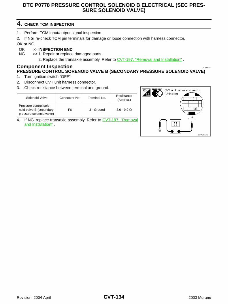
CVT-134
DTC P0778 PRESSURE CONTROL SOLENOID B ELECTRICAL (SEC PRES-SURE SOLENOID VALVE)
Revision; 2004 April 2003 Murano
4. CHECK TCM INSPECTION
1. Perform TCM input/output signal inspection.2. If NG, re-check TCM pin terminals for damage or loose connection with harness connector.OK or NGOK >> INSPECTION ENDNG >> 1. Repair or replace damaged parts.
2. Replace the transaxle assembly. Refer to CVT-197, "Removal and Installation" .
Component Inspection ACS002TI
PRESSURE CONTROL SORENOID VALVE B (SECONDARY PRESSURE SOLENOID VALVE)1. Turn ignition switch “OFF”.2. Disconnect CVT unit harness connector.3. Check resistance between terminal and ground.
4. If NG, replace transaxle assembly. Refer to CVT-197, "Removaland Installation" .
Solenoid Valve Connector No. Terminal No.Resistance (Approx.)
Pressure control sole-noid valve B (secondary pressure solenoid valve)
F6 3 - Ground 3.0 - 9.0 Ω
SCIA2032E
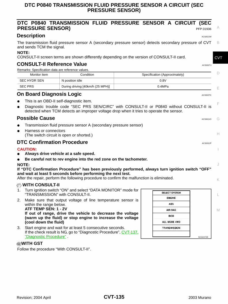
DTC P0840 TRANSMISSION FLUID PRESSURE SENSOR A CIRCUIT (SEC PRESSURE SENSOR)
CVT-135
D
E
F
G
H
I
J
K
L
M
A
B
CVT
Revision; 2004 April 2003 Murano
DTC P0840 TRANSMISSION FLUID PRESSURE SENSOR A CIRCUIT (SECPRESSURE SENSOR) PFP:31936
Description ACS002JM
The transmission fluid pressure sensor A (secondary pressure sensor) detects secondary pressure of CVTand sends TCM the signal.NOTE:CONSULT-II screen terms are shown differently depending on the version of CONSULT-II card.
CONSULT-II Reference Value ACS002TJ
Remarks: Specification data are reference values.
On Board Diagnosis Logic ACS002TK
This is an OBD-II self-diagnostic item. Diagnostic trouble code “SEC PRS SEN/CIRC” with CONSULT-II or P0840 without CONSULT-II is
detected when TCM detects an improper voltage drop when it tries to operate the sensor.
Possible Cause ACS002JO
Transmission fluid pressure sensor A (secondary pressure sensor) Harness or connectors
(The switch circuit is open or shorted.)
DTC Confirmation Procedure ACS002JP
CAUTION: Always drive vehicle at a safe speed. Be careful not to rev engine into the red zone on the tachometer.NOTE:If “DTC Confirmation Procedure” has been previously performed, always turn ignition switch “OFF”and wait at least 5 seconds before performing the next test.After the repair, perform the following procedure to confirm the malfunction is eliminated.
WITH CONSULT-II1. Turn ignition switch “ON” and select “DATA MONITOR” mode for
“TRANSMISSION” with CONSULT-II.2. Make sure that output voltage of line temperature sensor is
within the range below.ATF TEMP SEN: 1 - 2VIf out of range, drive the vehicle to decrease the voltage(warm up the fluid) or stop engine to increase the voltage(cool down the fluid)
3. Start engine and wait for at least 5 consecutive seconds.If the check result is NG, go to “Diagnostic Procedure”, CVT-137,"Diagnostic Procedure" .
WITH GSTFollow the procedure “With CONSULT-II”.
Monitor item Condition Specification (Approximately)
SEC HYDR SEN N position idle 0.8V
SEC PRS During driving [40km/h (25 MPH)] 0.4MPa
SCIA2272E

CVT-136
DTC P0840 TRANSMISSION FLUID PRESSURE SENSOR A CIRCUIT (SEC PRESSURE SENSOR)
Revision; 2004 April 2003 Murano
Wiring Diagram - CVT - SECPS ACS002TL
TCWA0155E
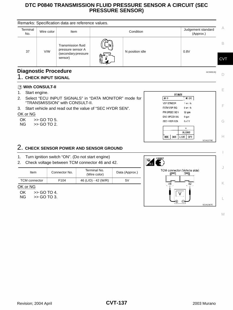
DTC P0840 TRANSMISSION FLUID PRESSURE SENSOR A CIRCUIT (SEC PRESSURE SENSOR)
CVT-137
D
E
F
G
H
I
J
K
L
M
A
B
CVT
Revision; 2004 April 2003 Murano
Remarks: Specification data are reference values.
Diagnostic Procedure ACS002JQ
1. CHECK INPUT SIGNAL
With CONSULT-II1. Start engine.2. Select “ECU INPUT SIGNALS” in “DATA MONITOR” mode for
“TRANSMISSION” with CONSULT-II.3. Start vehicle and read out the value of “SEC HYDR SEN”.OK or NGOK >> GO TO 5.NG >> GO TO 2.
2. CHECK SENSOR POWER AND SENSOR GROUND
1. Turn ignition switch “ON”. (Do not start engine)2. Check voltage between TCM connector 46 and 42.
OK or NGOK >> GO TO 4.NG >> GO TO 3.
Terminal No.
Wire color Item ConditionJudgement standard
(Approx.)
37 V/W
Transmission fluid pressure sensor A (secondary pressure sensor)
N position idle 0.8V
SCIA2279E
Item Connector No.Terminal No. (Wire color)
Data (Approx.)
TCM connector F104 46 (L/O) - 42 (W/R) 5V
SCIA2367E
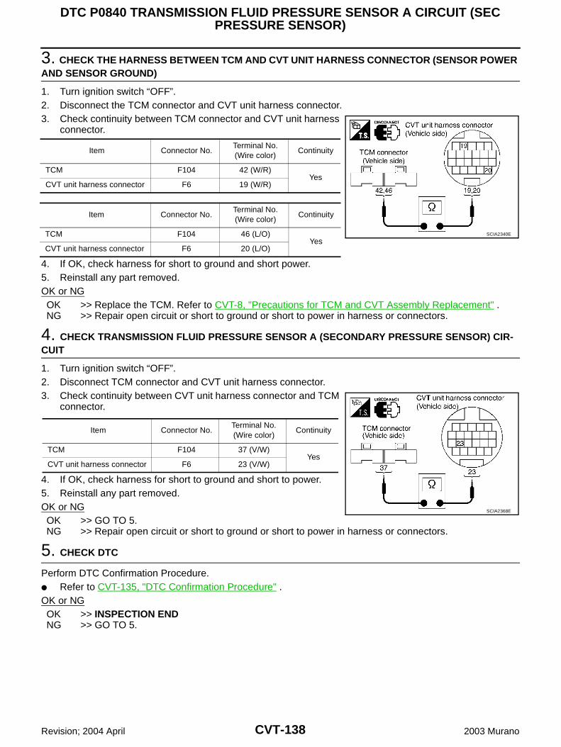
CVT-138
DTC P0840 TRANSMISSION FLUID PRESSURE SENSOR A CIRCUIT (SEC PRESSURE SENSOR)
Revision; 2004 April 2003 Murano
3. CHECK THE HARNESS BETWEEN TCM AND CVT UNIT HARNESS CONNECTOR (SENSOR POWER AND SENSOR GROUND)
1. Turn ignition switch “OFF”.2. Disconnect the TCM connector and CVT unit harness connector.3. Check continuity between TCM connector and CVT unit harness
connector.
4. If OK, check harness for short to ground and short power.5. Reinstall any part removed.OK or NGOK >> Replace the TCM. Refer to CVT-8, "Precautions for TCM and CVT Assembly Replacement" .NG >> Repair open circuit or short to ground or short to power in harness or connectors.
4. CHECK TRANSMISSION FLUID PRESSURE SENSOR A (SECONDARY PRESSURE SENSOR) CIR-CUIT
1. Turn ignition switch “OFF”.2. Disconnect TCM connector and CVT unit harness connector.3. Check continuity between CVT unit harness connector and TCM
connector.
4. If OK, check harness for short to ground and short to power.5. Reinstall any part removed.OK or NGOK >> GO TO 5.NG >> Repair open circuit or short to ground or short to power in harness or connectors.
5. CHECK DTC
Perform DTC Confirmation Procedure. Refer to CVT-135, "DTC Confirmation Procedure" .OK or NGOK >> INSPECTION ENDNG >> GO TO 5.
Item Connector No.Terminal No. (Wire color)
Continuity
TCM F104 42 (W/R)Yes
CVT unit harness connector F6 19 (W/R)
Item Connector No.Terminal No. (Wire color)
Continuity
TCM F104 46 (L/O)Yes
CVT unit harness connector F6 20 (L/O)
SCIA2340E
Item Connector No.Terminal No. (Wire color)
Continuity
TCM F104 37 (V/W)Yes
CVT unit harness connector F6 23 (V/W)
SCIA2368E
DTC P0840 TRANSMISSION FLUID PRESSURE SENSOR A CIRCUIT (SEC PRESSURE SENSOR)
CVT-139
D
E
F
G
H
I
J
K
L
M
A
B
CVT
Revision; 2004 April 2003 Murano
6. PERFORM TCM INSPECTION
1. Perform TCM input/output signal inspection.2. If NG, re-check TCM pin terminals for damage or loose connection with harness connector.OK or NGOK >> Replace the transaxle assembly. Refer to CVT-197, "Removal and Installation" .NG >> Repair or replace damaged parts.
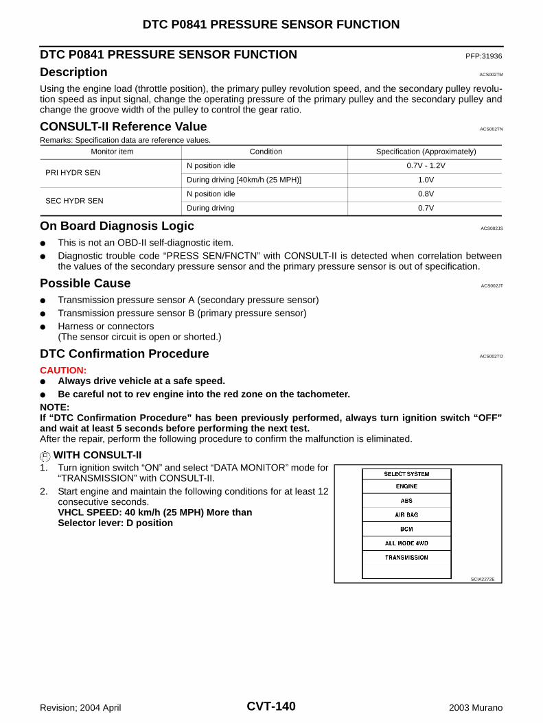
CVT-140
DTC P0841 PRESSURE SENSOR FUNCTION
Revision; 2004 April 2003 Murano
DTC P0841 PRESSURE SENSOR FUNCTION PFP:31936
Description ACS002TM
Using the engine load (throttle position), the primary pulley revolution speed, and the secondary pulley revolu-tion speed as input signal, change the operating pressure of the primary pulley and the secondary pulley andchange the groove width of the pulley to control the gear ratio.
CONSULT-II Reference Value ACS002TN
Remarks: Specification data are reference values.
On Board Diagnosis Logic ACS002JS
This is not an OBD-II self-diagnostic item. Diagnostic trouble code “PRESS SEN/FNCTN” with CONSULT-II is detected when correlation between
the values of the secondary pressure sensor and the primary pressure sensor is out of specification.
Possible Cause ACS002JT
Transmission pressure sensor A (secondary pressure sensor) Transmission pressure sensor B (primary pressure sensor) Harness or connectors
(The sensor circuit is open or shorted.)
DTC Confirmation Procedure ACS002TO
CAUTION: Always drive vehicle at a safe speed. Be careful not to rev engine into the red zone on the tachometer.NOTE:If “DTC Confirmation Procedure” has been previously performed, always turn ignition switch “OFF”and wait at least 5 seconds before performing the next test.After the repair, perform the following procedure to confirm the malfunction is eliminated.
WITH CONSULT-II1. Turn ignition switch “ON” and select “DATA MONITOR” mode for
“TRANSMISSION” with CONSULT-II.2. Start engine and maintain the following conditions for at least 12
consecutive seconds.VHCL SPEED: 40 km/h (25 MPH) More thanSelector lever: D position
Monitor item Condition Specification (Approximately)
PRI HYDR SENN position idle 0.7V - 1.2V
During driving [40km/h (25 MPH)] 1.0V
SEC HYDR SENN position idle 0.8V
During driving 0.7V
SCIA2272E
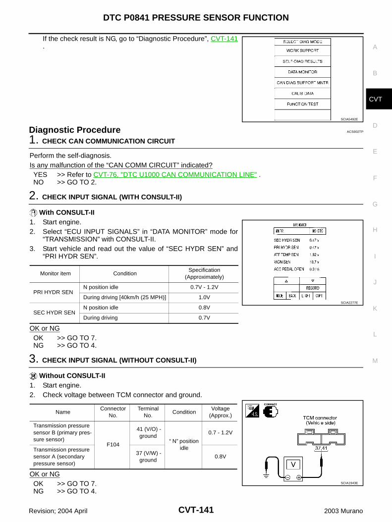
DTC P0841 PRESSURE SENSOR FUNCTION
CVT-141
D
E
F
G
H
I
J
K
L
M
A
B
CVT
Revision; 2004 April 2003 Murano
If the check result is NG, go to “Diagnostic Procedure”, CVT-141.
Diagnostic Procedure ACS002TP
1. CHECK CAN COMMUNICATION CIRCUIT
Perform the self-diagnosis.Is any malfunction of the “CAN COMM CIRCUIT” indicated?YES >> Refer to CVT-76, "DTC U1000 CAN COMMUNICATION LINE" .NO >> GO TO 2.
2. CHECK INPUT SIGNAL (WITH CONSULT-II)
With CONSULT-II1. Start engine.2. Select “ECU INPUT SIGNALS” in “DATA MONITOR” mode for
“TRANSMISSION” with CONSULT-II.3. Start vehicle and read out the value of “SEC HYDR SEN” and
“PRI HYDR SEN”.
OK or NGOK >> GO TO 7.NG >> GO TO 4.
3. CHECK INPUT SIGNAL (WITHOUT CONSULT-II)
Without CONSULT-II1. Start engine.2. Check voltage between TCM connector and ground.
OK or NGOK >> GO TO 7.NG >> GO TO 4.
SCIA5492E
Monitor item ConditionSpecification
(Approximately)
PRI HYDR SENN position idle 0.7V - 1.2V
During driving [40km/h (25 MPH)] 1.0V
SEC HYDR SENN position idle 0.8V
During driving 0.7V
SCIA2277E
NameConnector
No.Terminal
No.Condition
Voltage (Approx.)
Transmission pressure sensor B (primary pres-sure sensor)
F104
41 (V/O) - ground
“ N” position idle
0.7 - 1.2V
Transmission pressure sensor A (secondary pressure sensor)
37 (V/W) - ground
0.8V
SCIA1943E
CVT-142
DTC P0841 PRESSURE SENSOR FUNCTION
Revision; 2004 April 2003 Murano
4. CHECK LINE PRESSURE
Perform line pressure test. Refer to CVT-57, "LINE PRESSURE TEST" .OK or NGOK >> GO TO 5.NG >> Repair or replace damaged parts. Refer to CVT-58, "Judgement of Line Pressure Test" .
5. CHECK TRANSMISSION PRESSORE SENSOR A (SECONDARY PRESSURE SENSOR) SYSTEM AND TRANSMISSION PRESSURE SENSOR B (PRIMARY PRESSURE SENSOR) SYSTEM
Check secondary pressure sensor system and primary pressure sensor system. Refer to CVT-135, "DTCP0840 TRANSMISSION FLUID PRESSURE SENSOR A CIRCUIT (SEC PRESSURE SENSOR)" , CVT-143,"DTC P0845 TRANSMISSION FLUID PRESSURE SENSOR B CIRCUIT (PRI PRESSURE SENSOR)" .OK or NGOK >> GO TO 6.NG >> Repair or replace damaged parts.
6. DETECT MALFUNCTIONING ITEM
Check the following: Line pressure solenoid valve. Refer to CVT-124, "Component Inspection" . Secondary pressure solenoid valve. Refer to CVT-134, "Component Inspection" . Step motor. Refer to CVT-172, "Component Inspection" .OK or NGOK >> GO TO 7.NG >> Repair or replace damaged parts.
7. CHECK DTC
Perform DTC Confirmation Procedure. Refer to CVT-140, "DTC Confirmation Procedure" .OK or NGOK >> INSPECTION ENDNG >> Replace the TCM or transaxle assembly. Refer to CVT-197, "Removal and Installation" .
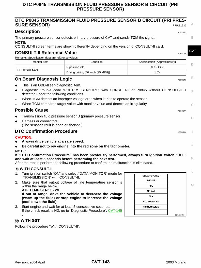
DTC P0845 TRANSMISSION FLUID PRESSURE SENSOR B CIRCUIT (PRI PRESSURE SENSOR)
CVT-143
D
E
F
G
H
I
J
K
L
M
A
B
CVT
Revision; 2004 April 2003 Murano
DTC P0845 TRANSMISSION FLUID PRESSURE SENSOR B CIRCUIT (PRI PRES-SURE SENSOR) PFP:31936
Description ACS002TQ
The primary pressure sensor detects primary pressure of CVT and sends TCM the signal.NOTE:CONSULT-II screen terms are shown differently depending on the version of CONSULT-II card.
CONSULT-II Reference Value ACS002TR
Remarks: Specification data are reference values.
On Board Diagnosis Logic ACS002TS
This is an OBD-II self-diagnostic item. Diagnostic trouble code “PRI PRS SEN/CIRC” with CONSULT-II or P0845 without CONSULT-II is
detected under the following conditions.– When TCM detects an improper voltage drop when it tries to operate the sensor.– When TCM compares target value with monitor value and detects an irregularity.
Possible Cause ACS002TT
Transmission fluid pressure sensor B (primary pressure sensor) Harness or connectors
(The sensor circuit is open or shorted.)
DTC Confirmation Procedure ACS002TU
CAUTION: Always drive vehicle at a safe speed. Be careful not to rev engine into the red zone on the tachometer.NOTE:If “DTC Confirmation Procedure” has been previously performed, always turn ignition switch “OFF”and wait at least 5 seconds before performing the next test.After the repair, perform the following procedure to confirm the malfunction is eliminated.
WITH CONSULT-II1. Turn ignition switch “ON” and select “DATA MONITOR” mode for
“TRANSMISSION” with CONSULT-II.2. Make sure that output voltage of line temperature sensor is
within the range below.ATF TEMP SEN: 1 - 2VIf out of range, drive the vehicle to decrease the voltage(warm up the fluid) or stop engine to increase the voltage(cool down the fluid).
3. Start engine and wait for at least 5 consecutive seconds.If the check result is NG, go to “Diagnostic Procedure”, CVT-145.
WITH GST
Follow the procedure “With CONSULT-II”.
Monitor item Condition Specification (Approximately)
PRI HYDR SENN position idle 0.7 - 1.2V
During driving [40 km/h (25 MPH)] 1.0V
SCIA2272E
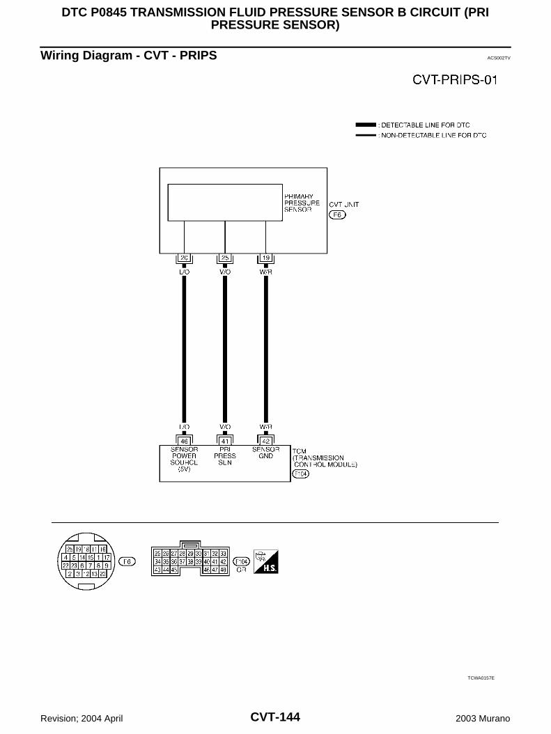
CVT-144
DTC P0845 TRANSMISSION FLUID PRESSURE SENSOR B CIRCUIT (PRI PRESSURE SENSOR)
Revision; 2004 April 2003 Murano
Wiring Diagram - CVT - PRIPS ACS002TV
TCWA0157E
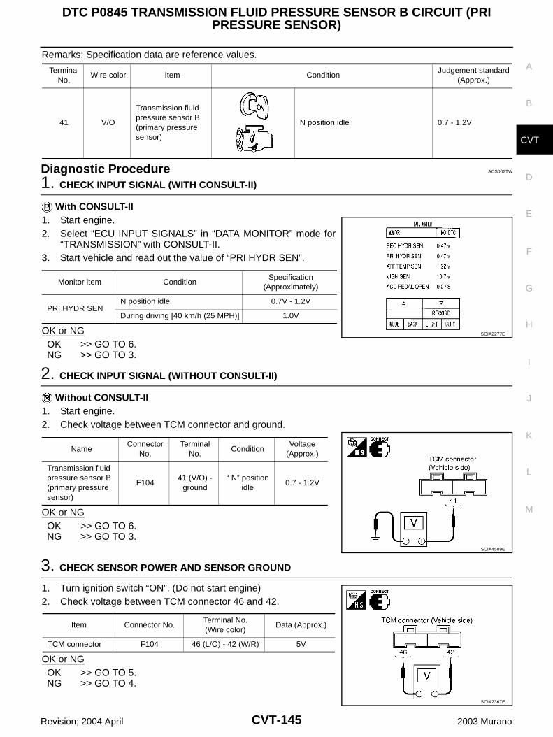
DTC P0845 TRANSMISSION FLUID PRESSURE SENSOR B CIRCUIT (PRI PRESSURE SENSOR)
CVT-145
D
E
F
G
H
I
J
K
L
M
A
B
CVT
Revision; 2004 April 2003 Murano
Remarks: Specification data are reference values.
Diagnostic Procedure ACS002TW
1. CHECK INPUT SIGNAL (WITH CONSULT-II)
With CONSULT-II1. Start engine.2. Select “ECU INPUT SIGNALS” in “DATA MONITOR” mode for
“TRANSMISSION” with CONSULT-II.3. Start vehicle and read out the value of “PRI HYDR SEN”.
OK or NGOK >> GO TO 6.NG >> GO TO 3.
2. CHECK INPUT SIGNAL (WITHOUT CONSULT-II)
Without CONSULT-II1. Start engine.2. Check voltage between TCM connector and ground.
OK or NGOK >> GO TO 6.NG >> GO TO 3.
3. CHECK SENSOR POWER AND SENSOR GROUND
1. Turn ignition switch “ON”. (Do not start engine)2. Check voltage between TCM connector 46 and 42.
OK or NGOK >> GO TO 5.NG >> GO TO 4.
Terminal No.
Wire color Item ConditionJudgement standard
(Approx.)
41 V/O
Transmission fluid pressure sensor B (primary pressure sensor)
N position idle 0.7 - 1.2V
Monitor item ConditionSpecification
(Approximately)
PRI HYDR SENN position idle 0.7V - 1.2V
During driving [40 km/h (25 MPH)] 1.0V
SCIA2277E
NameConnector
No.Terminal
No.Condition
Voltage (Approx.)
Transmission fluid pressure sensor B (primary pressure sensor)
F10441 (V/O) -
ground“ N” position
idle0.7 - 1.2V
SCIA4509E
Item Connector No.Terminal No. (Wire color)
Data (Approx.)
TCM connector F104 46 (L/O) - 42 (W/R) 5V
SCIA2367E
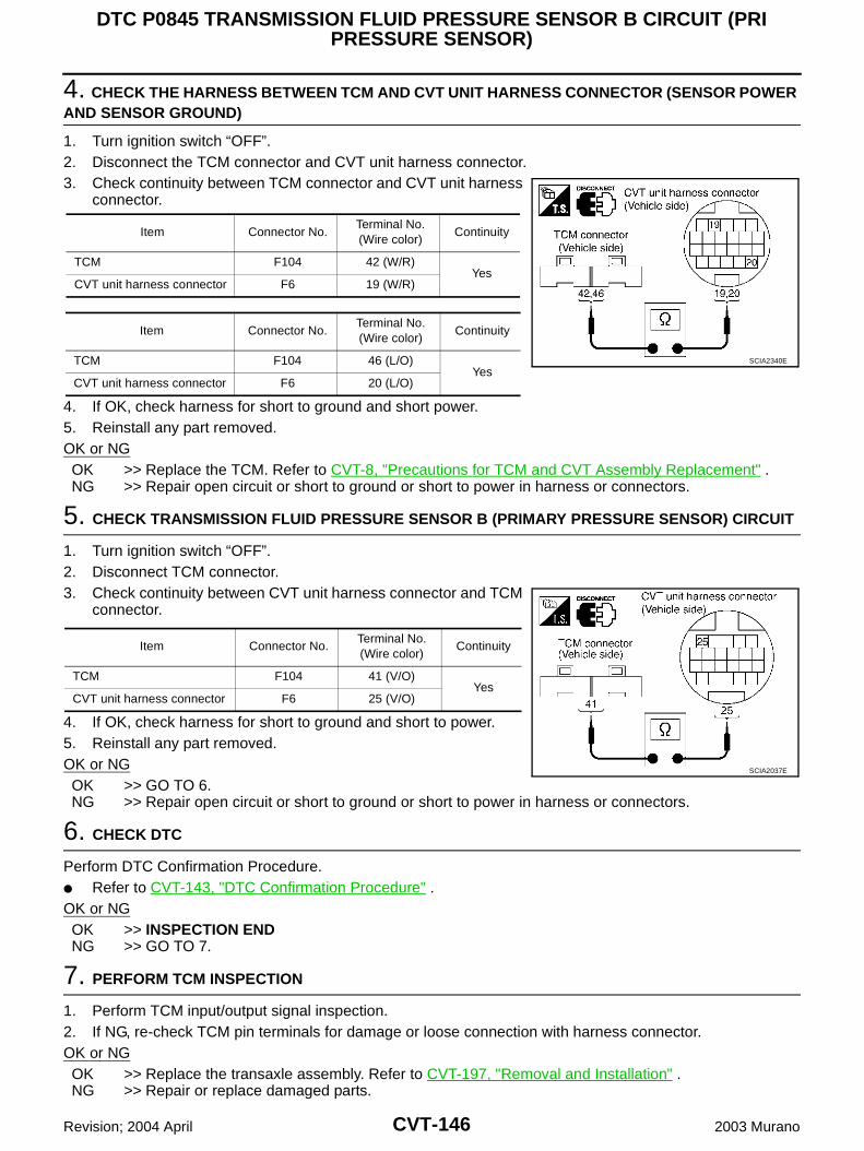
CVT-146
DTC P0845 TRANSMISSION FLUID PRESSURE SENSOR B CIRCUIT (PRI PRESSURE SENSOR)
Revision; 2004 April 2003 Murano
4. CHECK THE HARNESS BETWEEN TCM AND CVT UNIT HARNESS CONNECTOR (SENSOR POWER AND SENSOR GROUND)
1. Turn ignition switch “OFF”.2. Disconnect the TCM connector and CVT unit harness connector.3. Check continuity between TCM connector and CVT unit harness
connector.
4. If OK, check harness for short to ground and short power.5. Reinstall any part removed.OK or NGOK >> Replace the TCM. Refer to CVT-8, "Precautions for TCM and CVT Assembly Replacement" .NG >> Repair open circuit or short to ground or short to power in harness or connectors.
5. CHECK TRANSMISSION FLUID PRESSURE SENSOR B (PRIMARY PRESSURE SENSOR) CIRCUIT
1. Turn ignition switch “OFF”.2. Disconnect TCM connector.3. Check continuity between CVT unit harness connector and TCM
connector.
4. If OK, check harness for short to ground and short to power.5. Reinstall any part removed.OK or NGOK >> GO TO 6.NG >> Repair open circuit or short to ground or short to power in harness or connectors.
6. CHECK DTC
Perform DTC Confirmation Procedure. Refer to CVT-143, "DTC Confirmation Procedure" .OK or NGOK >> INSPECTION ENDNG >> GO TO 7.
7. PERFORM TCM INSPECTION
1. Perform TCM input/output signal inspection.2. If NG, re-check TCM pin terminals for damage or loose connection with harness connector.OK or NGOK >> Replace the transaxle assembly. Refer to CVT-197, "Removal and Installation" .NG >> Repair or replace damaged parts.
Item Connector No.Terminal No. (Wire color)
Continuity
TCM F104 42 (W/R)Yes
CVT unit harness connector F6 19 (W/R)
Item Connector No.Terminal No. (Wire color)
Continuity
TCM F104 46 (L/O)Yes
CVT unit harness connector F6 20 (L/O)
SCIA2340E
Item Connector No.Terminal No. (Wire color)
Continuity
TCM F104 41 (V/O)Yes
CVT unit harness connector F6 25 (V/O)
SCIA2037E
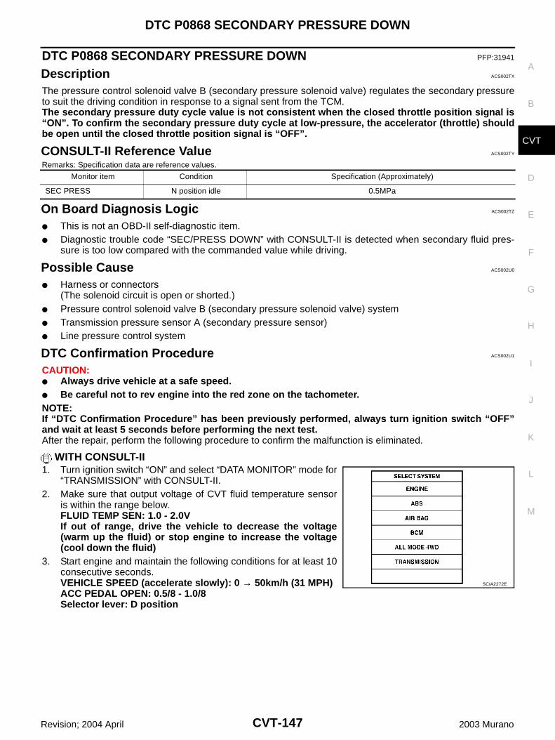
DTC P0868 SECONDARY PRESSURE DOWN
CVT-147
D
E
F
G
H
I
J
K
L
M
A
B
CVT
Revision; 2004 April 2003 Murano
DTC P0868 SECONDARY PRESSURE DOWN PFP:31941
Description ACS002TX
The pressure control solenoid valve B (secondary pressure solenoid valve) regulates the secondary pressureto suit the driving condition in response to a signal sent from the TCM.The secondary pressure duty cycle value is not consistent when the closed throttle position signal is“ON”. To confirm the secondary pressure duty cycle at low-pressure, the accelerator (throttle) shouldbe open until the closed throttle position signal is “OFF”.
CONSULT-II Reference Value ACS002TY
Remarks: Specification data are reference values.
On Board Diagnosis Logic ACS002TZ
This is not an OBD-II self-diagnostic item. Diagnostic trouble code “SEC/PRESS DOWN” with CONSULT-II is detected when secondary fluid pres-
sure is too low compared with the commanded value while driving.
Possible Cause ACS002U0
Harness or connectors(The solenoid circuit is open or shorted.)
Pressure control solenoid valve B (secondary pressure solenoid valve) system Transmission pressure sensor A (secondary pressure sensor) Line pressure control system
DTC Confirmation Procedure ACS002U1
CAUTION: Always drive vehicle at a safe speed. Be careful not to rev engine into the red zone on the tachometer.NOTE:If “DTC Confirmation Procedure” has been previously performed, always turn ignition switch “OFF”and wait at least 5 seconds before performing the next test.After the repair, perform the following procedure to confirm the malfunction is eliminated.
WITH CONSULT-II1. Turn ignition switch “ON” and select “DATA MONITOR” mode for
“TRANSMISSION” with CONSULT-II.2. Make sure that output voltage of CVT fluid temperature sensor
is within the range below.FLUID TEMP SEN: 1.0 - 2.0VIf out of range, drive the vehicle to decrease the voltage(warm up the fluid) or stop engine to increase the voltage(cool down the fluid)
3. Start engine and maintain the following conditions for at least 10consecutive seconds.VEHICLE SPEED (accelerate slowly): 0 → 50km/h (31 MPH)ACC PEDAL OPEN: 0.5/8 - 1.0/8Selector lever: D position
Monitor item Condition Specification (Approximately)
SEC PRESS N position idle 0.5MPa
SCIA2272E
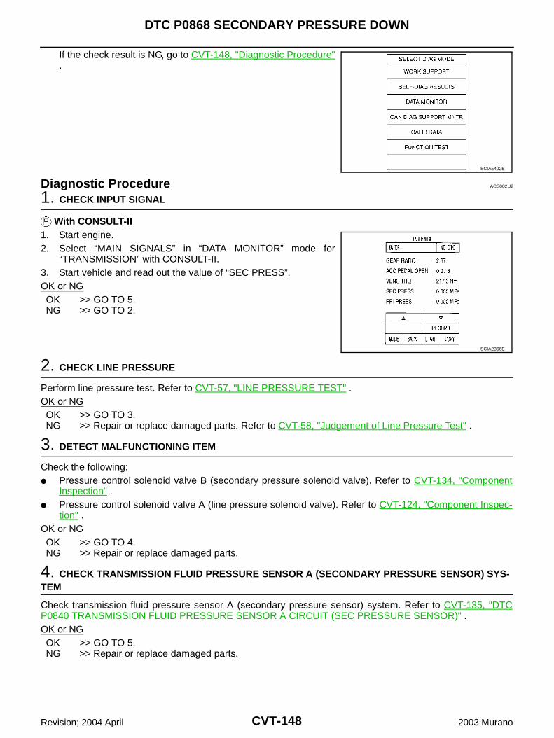
CVT-148
DTC P0868 SECONDARY PRESSURE DOWN
Revision; 2004 April 2003 Murano
If the check result is NG, go to CVT-148, "Diagnostic Procedure".
Diagnostic Procedure ACS002U2
1. CHECK INPUT SIGNAL
With CONSULT-II1. Start engine.2. Select “MAIN SIGNALS” in “DATA MONITOR” mode for
“TRANSMISSION” with CONSULT-II.3. Start vehicle and read out the value of “SEC PRESS”.OK or NGOK >> GO TO 5.NG >> GO TO 2.
2. CHECK LINE PRESSURE
Perform line pressure test. Refer to CVT-57, "LINE PRESSURE TEST" .OK or NGOK >> GO TO 3.NG >> Repair or replace damaged parts. Refer to CVT-58, "Judgement of Line Pressure Test" .
3. DETECT MALFUNCTIONING ITEM
Check the following: Pressure control solenoid valve B (secondary pressure solenoid valve). Refer to CVT-134, "Component
Inspection" . Pressure control solenoid valve A (line pressure solenoid valve). Refer to CVT-124, "Component Inspec-
tion" .OK or NGOK >> GO TO 4.NG >> Repair or replace damaged parts.
4. CHECK TRANSMISSION FLUID PRESSURE SENSOR A (SECONDARY PRESSURE SENSOR) SYS-TEM
Check transmission fluid pressure sensor A (secondary pressure sensor) system. Refer to CVT-135, "DTCP0840 TRANSMISSION FLUID PRESSURE SENSOR A CIRCUIT (SEC PRESSURE SENSOR)" .OK or NGOK >> GO TO 5.NG >> Repair or replace damaged parts.
SCIA5492E
SCIA2366E
DTC P0868 SECONDARY PRESSURE DOWN
CVT-149
D
E
F
G
H
I
J
K
L
M
A
B
CVT
Revision; 2004 April 2003 Murano
5. DETECT MALFUNCTIONING ITEM
Check the following: Power supply and ground circuit for TCM. The TCM pin terminals for damage or loose connection with harness connector.OK or NGOK >> GO TO 6.NG >> Repair or replace damaged parts.
6. CHECK DTC
Perform DTC Confirmation Procedure. Refer to CVT-147, "DTC Confirmation Procedure" .OK or NGOK >> INSPECTION ENDNG >> Replace the transaxle assembly. Refer to CVT-197, "Removal and Installation" .
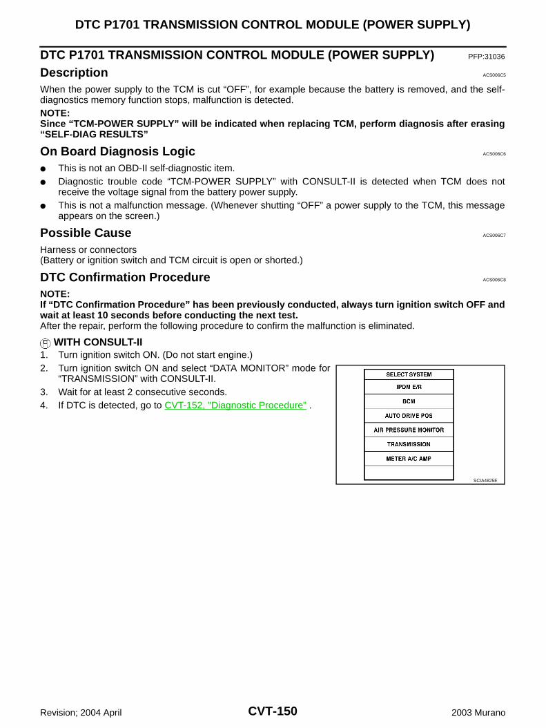
CVT-150
DTC P1701 TRANSMISSION CONTROL MODULE (POWER SUPPLY)
Revision; 2004 April 2003 Murano
DTC P1701 TRANSMISSION CONTROL MODULE (POWER SUPPLY) PFP:31036
Description ACS006C5
When the power supply to the TCM is cut “OFF”, for example because the battery is removed, and the self-diagnostics memory function stops, malfunction is detected.NOTE:Since “TCM-POWER SUPPLY” will be indicated when replacing TCM, perform diagnosis after erasing“SELF-DIAG RESULTS”
On Board Diagnosis Logic ACS006C6
This is not an OBD-II self-diagnostic item. Diagnostic trouble code “TCM-POWER SUPPLY” with CONSULT-II is detected when TCM does not
receive the voltage signal from the battery power supply. This is not a malfunction message. (Whenever shutting “OFF” a power supply to the TCM, this message
appears on the screen.)
Possible Cause ACS006C7
Harness or connectors(Battery or ignition switch and TCM circuit is open or shorted.)
DTC Confirmation Procedure ACS006C8
NOTE:If “DTC Confirmation Procedure” has been previously conducted, always turn ignition switch OFF andwait at least 10 seconds before conducting the next test.After the repair, perform the following procedure to confirm the malfunction is eliminated.
WITH CONSULT-II1. Turn ignition switch ON. (Do not start engine.)2. Turn ignition switch ON and select “DATA MONITOR” mode for
“TRANSMISSION” with CONSULT-II.3. Wait for at least 2 consecutive seconds.4. If DTC is detected, go to CVT-152, "Diagnostic Procedure" .
SCIA4825E
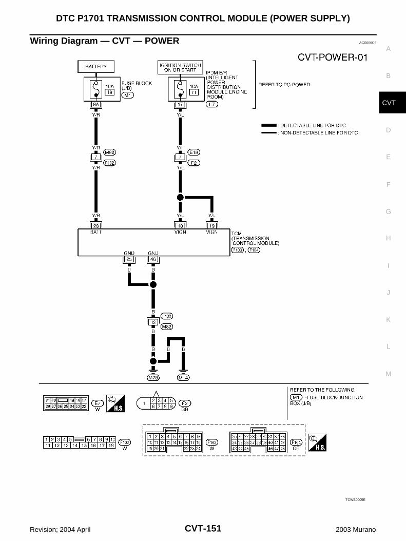
DTC P1701 TRANSMISSION CONTROL MODULE (POWER SUPPLY)
CVT-151
D
E
F
G
H
I
J
K
L
M
A
B
CVT
Revision; 2004 April 2003 Murano
Wiring Diagram — CVT — POWER ACS006C9
TCWB0005E
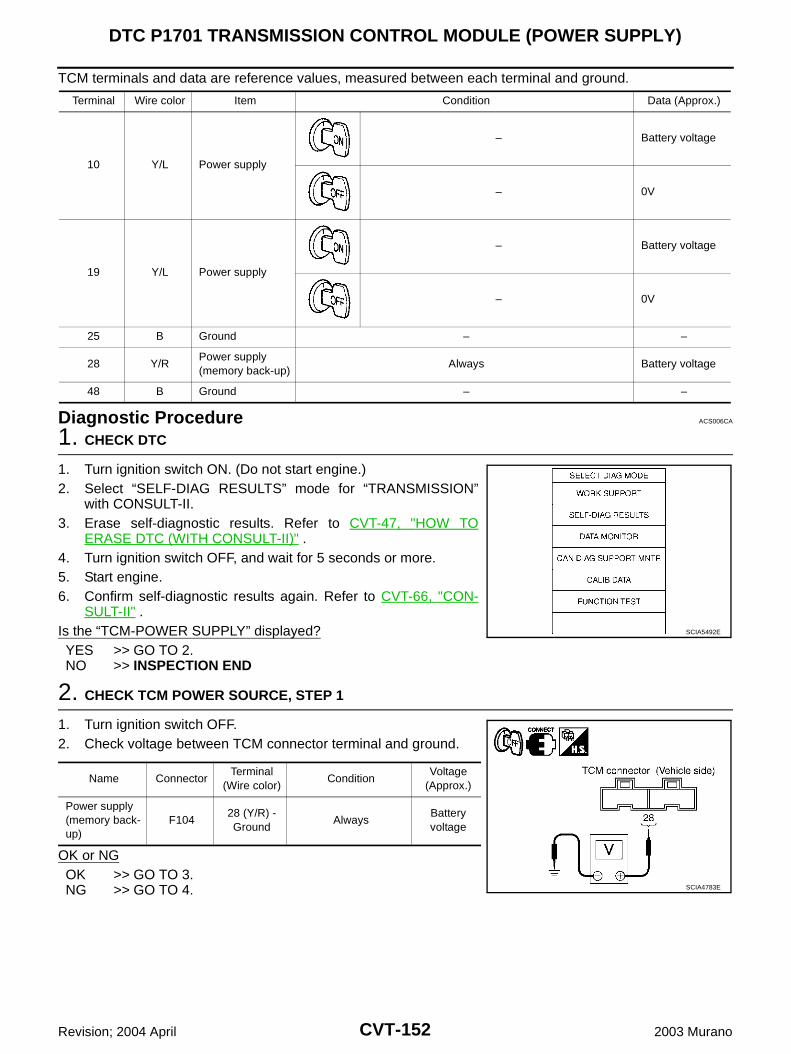
CVT-152
DTC P1701 TRANSMISSION CONTROL MODULE (POWER SUPPLY)
Revision; 2004 April 2003 Murano
TCM terminals and data are reference values, measured between each terminal and ground.
Diagnostic Procedure ACS006CA
1. CHECK DTC
1. Turn ignition switch ON. (Do not start engine.)2. Select “SELF-DIAG RESULTS” mode for “TRANSMISSION”
with CONSULT-II.3. Erase self-diagnostic results. Refer to CVT-47, "HOW TO
ERASE DTC (WITH CONSULT-II)" .4. Turn ignition switch OFF, and wait for 5 seconds or more.5. Start engine.6. Confirm self-diagnostic results again. Refer to CVT-66, "CON-
SULT-II" .Is the “TCM-POWER SUPPLY” displayed?YES >> GO TO 2.NO >> INSPECTION END
2. CHECK TCM POWER SOURCE, STEP 1
1. Turn ignition switch OFF.2. Check voltage between TCM connector terminal and ground.
OK or NGOK >> GO TO 3.NG >> GO TO 4.
Terminal Wire color Item Condition Data (Approx.)
10 Y/L Power supply
– Battery voltage
– 0V
19 Y/L Power supply
– Battery voltage
– 0V
25 B Ground – –
28 Y/RPower supply (memory back-up)
Always Battery voltage
48 B Ground – –
SCIA5492E
Name ConnectorTerminal
(Wire color)Condition
Voltage (Approx.)
Power supply (memory back-up)
F10428 (Y/R) - Ground
AlwaysBattery voltage
SCIA4783E
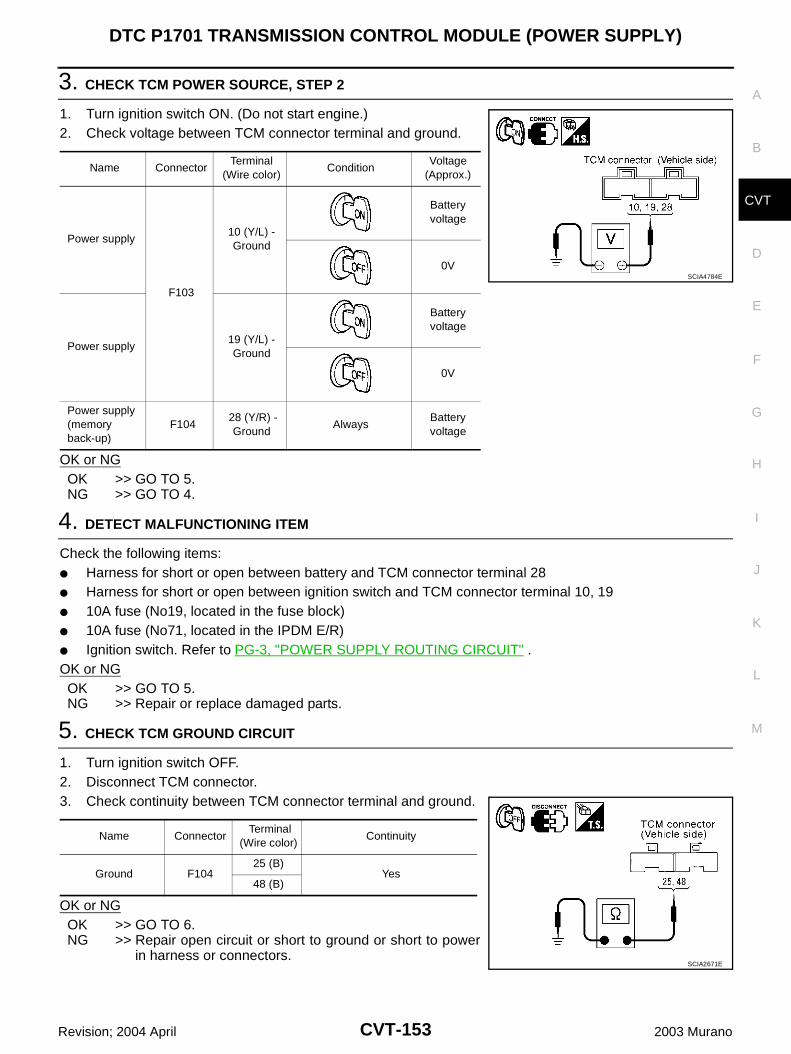
DTC P1701 TRANSMISSION CONTROL MODULE (POWER SUPPLY)
CVT-153
D
E
F
G
H
I
J
K
L
M
A
B
CVT
Revision; 2004 April 2003 Murano
3. CHECK TCM POWER SOURCE, STEP 2
1. Turn ignition switch ON. (Do not start engine.)2. Check voltage between TCM connector terminal and ground.
OK or NGOK >> GO TO 5.NG >> GO TO 4.
4. DETECT MALFUNCTIONING ITEM
Check the following items: Harness for short or open between battery and TCM connector terminal 28 Harness for short or open between ignition switch and TCM connector terminal 10, 19 10A fuse (No19, located in the fuse block) 10A fuse (No71, located in the IPDM E/R) Ignition switch. Refer to PG-3, "POWER SUPPLY ROUTING CIRCUIT" .OK or NGOK >> GO TO 5.NG >> Repair or replace damaged parts.
5. CHECK TCM GROUND CIRCUIT
1. Turn ignition switch OFF.2. Disconnect TCM connector.3. Check continuity between TCM connector terminal and ground.
OK or NGOK >> GO TO 6.NG >> Repair open circuit or short to ground or short to power
in harness or connectors.
Name ConnectorTerminal
(Wire color)Condition
Voltage (Approx.)
Power supply
F103
10 (Y/L) - Ground
Battery voltage
0V
Power supply19 (Y/L) - Ground
Battery voltage
0V
Power supply (memory back-up)
F104 28 (Y/R) -
GroundAlways
Battery voltage
SCIA4784E
Name Connector Terminal
(Wire color)Continuity
Ground F10425 (B)
Yes48 (B)
SCIA2671E
CVT-154
DTC P1701 TRANSMISSION CONTROL MODULE (POWER SUPPLY)
Revision; 2004 April 2003 Murano
6. CHECK DTC
Check again. Refer to CVT-150, "DTC Confirmation Procedure" .OK or NGOK >> INSPECTION ENDNG >> GO TO 7.
7. CHECK TCM
1. Check TCM input/output signal. Refer to CVT-63, "TCM Input/Output Signal Reference Values" .2. If NG, recheck TCM pin terminals for damage or loose connection with harness connector.OK or NGOK >> INSPECTION ENDNG >> Repair or replace damaged parts.
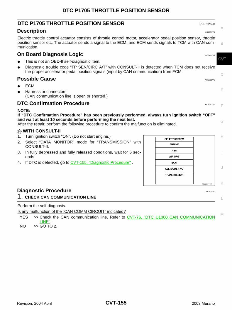
DTC P1705 THROTTLE POSITION SENSOR
CVT-155
D
E
F
G
H
I
J
K
L
M
A
B
CVT
Revision; 2004 April 2003 Murano
DTC P1705 THROTTLE POSITION SENSOR PFP:22620
Description ACS001VE
Electric throttle control actuator consists of throttle control motor, accelerator pedal position sensor, throttleposition sensor etc. The actuator sends a signal to the ECM, and ECM sends signals to TCM with CAN com-munication.
On Board Diagnosis Logic ACS001VF
This is not an OBD-II self-diagnostic item. Diagnostic trouble code “TP SEN/CIRC A/T” with CONSULT-II is detected when TCM does not receive
the proper accelerator pedal position signals (input by CAN communication) from ECM.
Possible Cause ACS001VG
ECM Harness or connectors
(CAN communication line is open or shorted.)
DTC Confirmation Procedure ACS001VH
NOTE:If “DTC Confirmation Procedure” has been previously performed, always turn ignition switch “OFF”and wait at least 10 seconds before performing the next test.After the repair, perform the following procedure to confirm the malfunction is eliminated.
WITH CONSULT-II1. Turn ignition switch “ON”. (Do not start engine.)2. Select “DATA MONITOR” mode for “TRANSMISSION” with
CONSULT-II.3. In fully depressed and fully released conditions, wait for 5 sec-
onds.4. If DTC is detected, go to CVT-155, "Diagnostic Procedure" .
Diagnostic Procedure ACS001VI
1. CHECK CAN COMMUNICATION LINE
Perform the self-diagnosis.Is any malfunction of the “CAN COMM CIRCUIT” indicated?YES >> Check the CAN communication line. Refer to CVT-76, "DTC U1000 CAN COMMUNICATION
LINE" .NO >> GO TO 2.
SCIA2272E
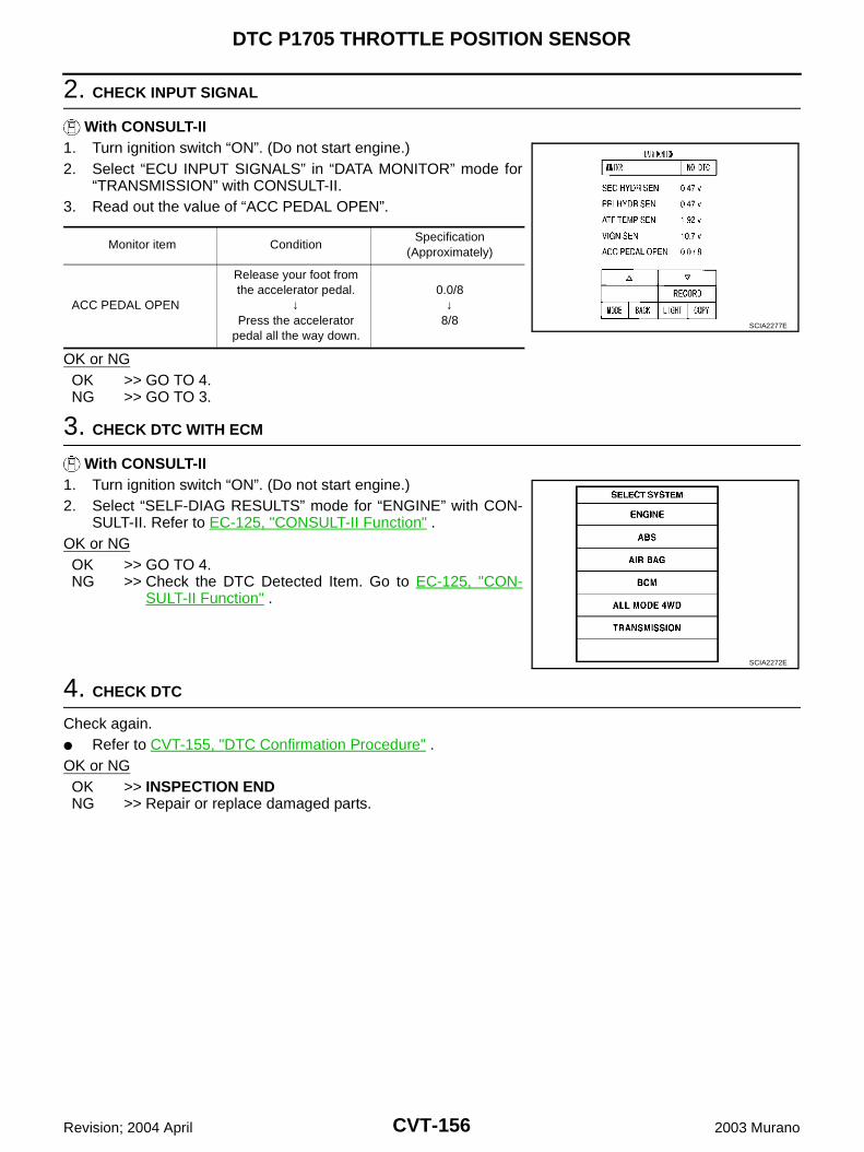
CVT-156
DTC P1705 THROTTLE POSITION SENSOR
Revision; 2004 April 2003 Murano
2. CHECK INPUT SIGNAL
With CONSULT-II1. Turn ignition switch “ON”. (Do not start engine.)2. Select “ECU INPUT SIGNALS” in “DATA MONITOR” mode for
“TRANSMISSION” with CONSULT-II.3. Read out the value of “ACC PEDAL OPEN”.
OK or NGOK >> GO TO 4.NG >> GO TO 3.
3. CHECK DTC WITH ECM
With CONSULT-II1. Turn ignition switch “ON”. (Do not start engine.)2. Select “SELF-DIAG RESULTS” mode for “ENGINE” with CON-
SULT-II. Refer to EC-125, "CONSULT-II Function" .OK or NGOK >> GO TO 4.NG >> Check the DTC Detected Item. Go to EC-125, "CON-
SULT-II Function" .
4. CHECK DTC
Check again. Refer to CVT-155, "DTC Confirmation Procedure" .OK or NGOK >> INSPECTION ENDNG >> Repair or replace damaged parts.
Monitor item ConditionSpecification
(Approximately)
ACC PEDAL OPEN
Release your foot from the accelerator pedal.
↓Press the accelerator
pedal all the way down.
0.0/8↓
8/8 SCIA2277E
SCIA2272E
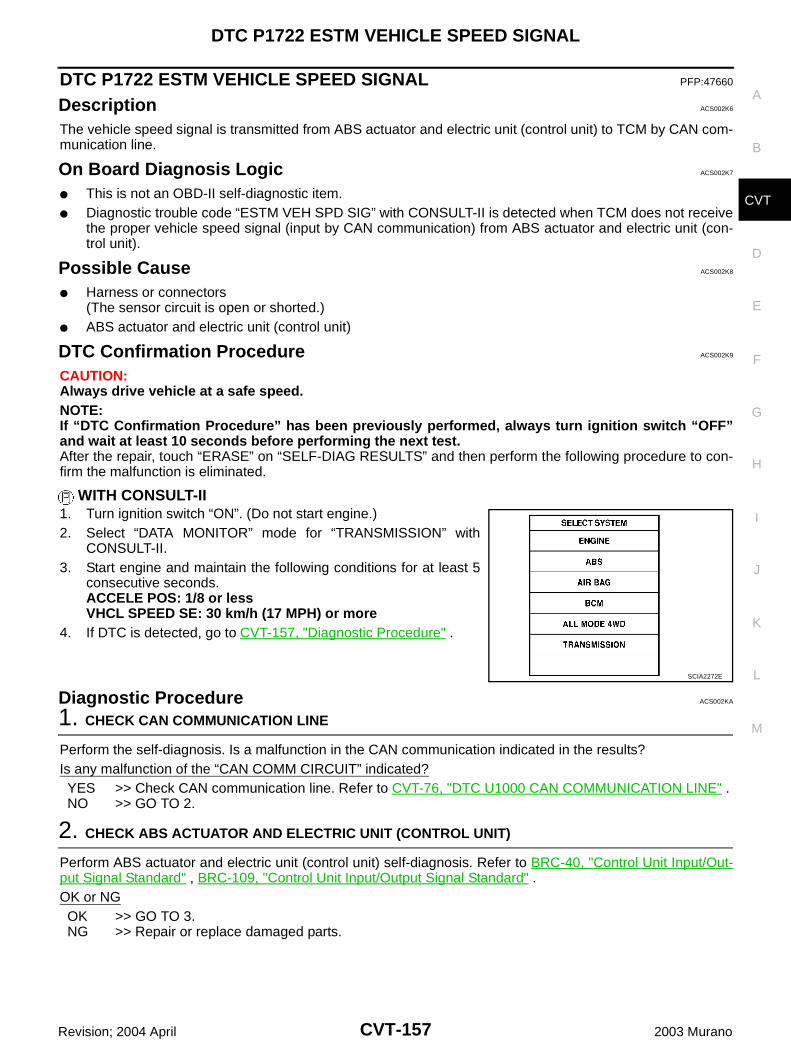
DTC P1722 ESTM VEHICLE SPEED SIGNAL
CVT-157
D
E
F
G
H
I
J
K
L
M
A
B
CVT
Revision; 2004 April 2003 Murano
DTC P1722 ESTM VEHICLE SPEED SIGNAL PFP:47660
Description ACS002K6
The vehicle speed signal is transmitted from ABS actuator and electric unit (control unit) to TCM by CAN com-munication line.
On Board Diagnosis Logic ACS002K7
This is not an OBD-II self-diagnostic item. Diagnostic trouble code “ESTM VEH SPD SIG” with CONSULT-II is detected when TCM does not receive
the proper vehicle speed signal (input by CAN communication) from ABS actuator and electric unit (con-trol unit).
Possible Cause ACS002K8
Harness or connectors(The sensor circuit is open or shorted.)
ABS actuator and electric unit (control unit)
DTC Confirmation Procedure ACS002K9
CAUTION:Always drive vehicle at a safe speed.NOTE:If “DTC Confirmation Procedure” has been previously performed, always turn ignition switch “OFF”and wait at least 10 seconds before performing the next test.After the repair, touch “ERASE” on “SELF-DIAG RESULTS” and then perform the following procedure to con-firm the malfunction is eliminated.
WITH CONSULT-II1. Turn ignition switch “ON”. (Do not start engine.)2. Select “DATA MONITOR” mode for “TRANSMISSION” with
CONSULT-II.3. Start engine and maintain the following conditions for at least 5
consecutive seconds.ACCELE POS: 1/8 or lessVHCL SPEED SE: 30 km/h (17 MPH) or more
4. If DTC is detected, go to CVT-157, "Diagnostic Procedure" .
Diagnostic Procedure ACS002KA
1. CHECK CAN COMMUNICATION LINE
Perform the self-diagnosis. Is a malfunction in the CAN communication indicated in the results?Is any malfunction of the “CAN COMM CIRCUIT” indicated?YES >> Check CAN communication line. Refer to CVT-76, "DTC U1000 CAN COMMUNICATION LINE" .NO >> GO TO 2.
2. CHECK ABS ACTUATOR AND ELECTRIC UNIT (CONTROL UNIT)
Perform ABS actuator and electric unit (control unit) self-diagnosis. Refer to BRC-40, "Control Unit Input/Out-put Signal Standard" , BRC-109, "Control Unit Input/Output Signal Standard" .OK or NGOK >> GO TO 3.NG >> Repair or replace damaged parts.
SCIA2272E
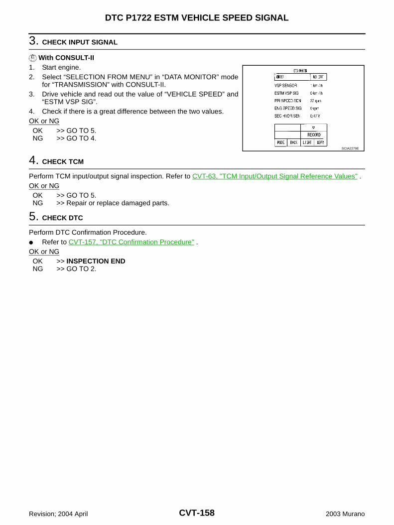
CVT-158
DTC P1722 ESTM VEHICLE SPEED SIGNAL
Revision; 2004 April 2003 Murano
3. CHECK INPUT SIGNAL
With CONSULT-II1. Start engine.2. Select “SELECTION FROM MENU” in “DATA MONITOR” mode
for “TRANSMISSION” with CONSULT-II.3. Drive vehicle and read out the value of “VEHICLE SPEED” and
“ESTM VSP SIG”.4. Check if there is a great difference between the two values.OK or NGOK >> GO TO 5.NG >> GO TO 4.
4. CHECK TCM
Perform TCM input/output signal inspection. Refer to CVT-63, "TCM Input/Output Signal Reference Values" .OK or NGOK >> GO TO 5.NG >> Repair or replace damaged parts.
5. CHECK DTC
Perform DTC Confirmation Procedure. Refer to CVT-157, "DTC Confirmation Procedure" .OK or NGOK >> INSPECTION ENDNG >> GO TO 2.
SCIA2279E
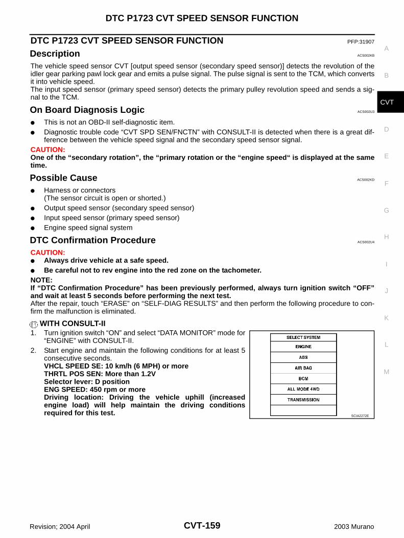
DTC P1723 CVT SPEED SENSOR FUNCTION
CVT-159
D
E
F
G
H
I
J
K
L
M
A
B
CVT
Revision; 2004 April 2003 Murano
DTC P1723 CVT SPEED SENSOR FUNCTION PFP:31907
Description ACS002KB
The vehicle speed sensor CVT [output speed sensor (secondary speed sensor)] detects the revolution of theidler gear parking pawl lock gear and emits a pulse signal. The pulse signal is sent to the TCM, which convertsit into vehicle speed.The input speed sensor (primary speed sensor) detects the primary pulley revolution speed and sends a sig-nal to the TCM.
On Board Diagnosis Logic ACS002U3
This is not an OBD-II self-diagnostic item. Diagnostic trouble code “CVT SPD SEN/FNCTN” with CONSULT-II is detected when there is a great dif-
ference between the vehicle speed signal and the secondary speed sensor signal.CAUTION:One of the “secondary rotation”, the “primary rotation or the “engine speed“ is displayed at the sametime.
Possible Cause ACS002KD
Harness or connectors(The sensor circuit is open or shorted.)
Output speed sensor (secondary speed sensor) Input speed sensor (primary speed sensor) Engine speed signal system
DTC Confirmation Procedure ACS002U4
CAUTION: Always drive vehicle at a safe speed. Be careful not to rev engine into the red zone on the tachometer.NOTE:If “DTC Confirmation Procedure” has been previously performed, always turn ignition switch “OFF”and wait at least 5 seconds before performing the next test.After the repair, touch “ERASE” on “SELF-DIAG RESULTS” and then perform the following procedure to con-firm the malfunction is eliminated.
WITH CONSULT-II1. Turn ignition switch “ON” and select “DATA MONITOR” mode for
“ENGINE” with CONSULT-II.2. Start engine and maintain the following conditions for at least 5
consecutive seconds.VHCL SPEED SE: 10 km/h (6 MPH) or moreTHRTL POS SEN: More than 1.2VSelector lever: D positionENG SPEED: 450 rpm or moreDriving location: Driving the vehicle uphill (increasedengine load) will help maintain the driving conditionsrequired for this test. SCIA2272E
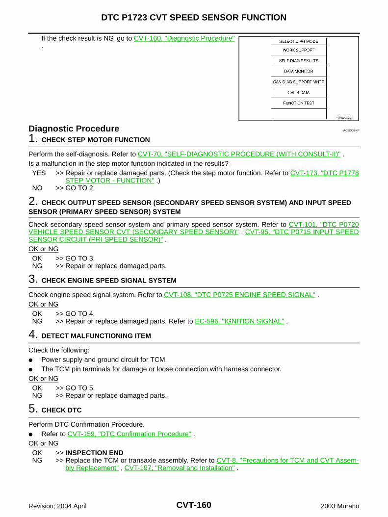
CVT-160
DTC P1723 CVT SPEED SENSOR FUNCTION
Revision; 2004 April 2003 Murano
If the check result is NG, go to CVT-160, "Diagnostic Procedure".
Diagnostic Procedure ACS002KF
1. CHECK STEP MOTOR FUNCTION
Perform the self-diagnosis. Refer to CVT-70, "SELF-DIAGNOSTIC PROCEDURE (WITH CONSULT-II)" .Is a malfunction in the step motor function indicated in the results?YES >> Repair or replace damaged parts. (Check the step motor function. Refer to CVT-173, "DTC P1778
STEP MOTOR - FUNCTION" .)NO >> GO TO 2.
2. CHECK OUTPUT SPEED SENSOR (SECONDARY SPEED SENSOR SYSTEM) AND INPUT SPEED SENSOR (PRIMARY SPEED SENSOR) SYSTEM
Check secondary speed sensor system and primary speed sensor system. Refer to CVT-101, "DTC P0720VEHICLE SPEED SENSOR CVT (SECONDARY SPEED SENSOR)" , CVT-95, "DTC P0715 INPUT SPEEDSENSOR CIRCUIT (PRI SPEED SENSOR)" .OK or NGOK >> GO TO 3.NG >> Repair or replace damaged parts.
3. CHECK ENGINE SPEED SIGNAL SYSTEM
Check engine speed signal system. Refer to CVT-108, "DTC P0725 ENGINE SPEED SIGNAL" .OK or NGOK >> GO TO 4.NG >> Repair or replace damaged parts. Refer to EC-596, "IGNITION SIGNAL" .
4. DETECT MALFUNCTIONING ITEM
Check the following: Power supply and ground circuit for TCM. The TCM pin terminals for damage or loose connection with harness connector.OK or NGOK >> GO TO 5.NG >> Repair or replace damaged parts.
5. CHECK DTC
Perform DTC Confirmation Procedure. Refer to CVT-159, "DTC Confirmation Procedure" .OK or NGOK >> INSPECTION ENDNG >> Replace the TCM or transaxle assembly. Refer to CVT-8, "Precautions for TCM and CVT Assem-
bly Replacement" , CVT-197, "Removal and Installation" .
SCIA5492E
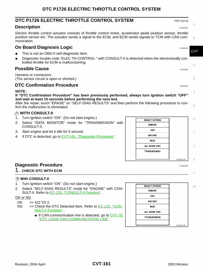
DTC P1726 ELECTRIC THROTTLE CONTROL SYSTEM
CVT-161
D
E
F
G
H
I
J
K
L
M
A
B
CVT
Revision; 2004 April 2003 Murano
DTC P1726 ELECTRIC THROTTLE CONTROL SYSTEM PFP:23710
Description ACS002KG
Electric throttle control actuator consists of throttle control motor, accelerator pedal position sensor, throttleposition sensor etc. The actuator sends a signal to the ECM, and ECM sends signals to TCM with CAN com-munication.
On Board Diagnosis Logic ACS002U5
This is not an OBD-II self-diagnostic item. Diagnostic trouble code “ELEC TH CONTROL·” with CONSULT-II is detected when the electronically con-
trolled throttle for ECM is malfunctioning.
Possible Cause ACS002KI
Harness or connectors(The sensor circuit is open or shorted.)
DTC Confirmation Procedure ACS002KJ
NOTE:If “DTC Confirmation Procedure” has been previously performed, always turn ignition switch “OFF”and wait at least 10 seconds before performing the next test.After the repair, touch “ERASE” on “SELF-DIAG RESULTS” and then perform the following procedure to con-firm the malfunction is eliminated.
WITH CONSULT-II1. Turn ignition switch “ON”. (Do not start engine.)2. Select “DATA MONITOR” mode for “TRANSMISSION” with
CONSULT-II.3. Start engine and let it idle for 5 second.4. If DTC is detected, go to CVT-161, "Diagnostic Procedure" .
Diagnostic Procedure ACS002KK
1. CHECK DTC WITH ECM
With CONSULT-II1. Turn ignition switch “ON”. (Do not start engine.)2. Select “SELF-DIAG RESULTS” mode for “ENGINE” with CON-
SULT-II. Refer to EC-125, "CONSULT-II Function" .OK or NGOK >> GO TO 2.NG >> Check the DTC Detected Item. Refer to EC-125, "CON-
SULT-II Function" . If CAN communication line is detected, go to CVT-76,
"DTC U1000 CAN COMMUNICATION LINE" .
SCIA2272E
SCIA2272E
CVT-162
DTC P1726 ELECTRIC THROTTLE CONTROL SYSTEM
Revision; 2004 April 2003 Murano
2. CHECK DTC
Perform DTC Confirmation Procedure. Refer to CVT-161, "DTC Confirmation Procedure" .OK or NGOK >> INSPECTION ENDNG >> GO TO 3.
3. DETECT MALFUNCTIONING ITEM
Check the following: The TCM pin terminals for damage or loose connection with harness connector.OK or NGOK >> Replace the TCM. Refer to CVT-8, "Precautions for TCM and CVT Assembly Replacement" .NG >> Repair or replace damaged parts.
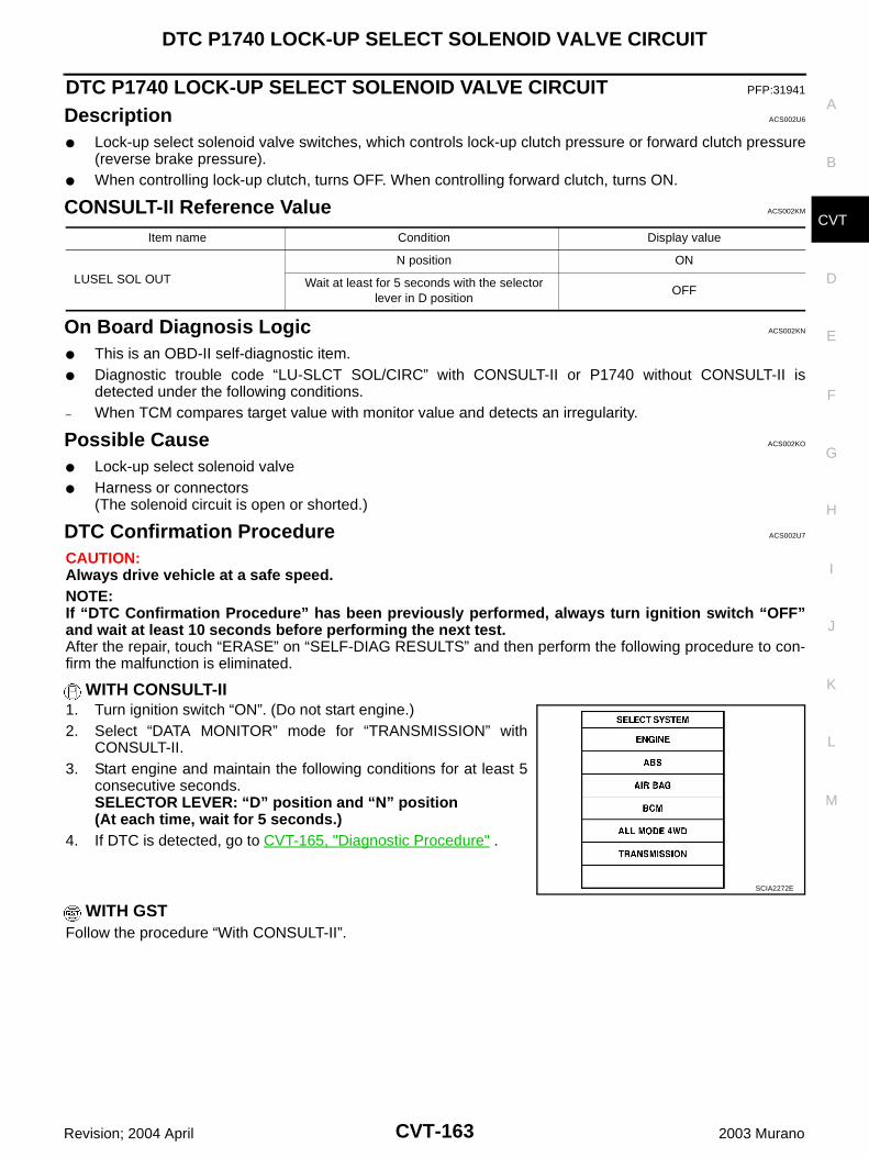
DTC P1740 LOCK-UP SELECT SOLENOID VALVE CIRCUIT
CVT-163
D
E
F
G
H
I
J
K
L
M
A
B
CVT
Revision; 2004 April 2003 Murano
DTC P1740 LOCK-UP SELECT SOLENOID VALVE CIRCUIT PFP:31941
Description ACS002U6
Lock-up select solenoid valve switches, which controls lock-up clutch pressure or forward clutch pressure(reverse brake pressure).
When controlling lock-up clutch, turns OFF. When controlling forward clutch, turns ON.
CONSULT-II Reference Value ACS002KM
On Board Diagnosis Logic ACS002KN
This is an OBD-II self-diagnostic item. Diagnostic trouble code “LU-SLCT SOL/CIRC” with CONSULT-II or P1740 without CONSULT-II is
detected under the following conditions.– When TCM compares target value with monitor value and detects an irregularity.
Possible Cause ACS002KO
Lock-up select solenoid valve Harness or connectors
(The solenoid circuit is open or shorted.)
DTC Confirmation Procedure ACS002U7
CAUTION:Always drive vehicle at a safe speed.NOTE:If “DTC Confirmation Procedure” has been previously performed, always turn ignition switch “OFF”and wait at least 10 seconds before performing the next test.After the repair, touch “ERASE” on “SELF-DIAG RESULTS” and then perform the following procedure to con-firm the malfunction is eliminated.
WITH CONSULT-II1. Turn ignition switch “ON”. (Do not start engine.)2. Select “DATA MONITOR” mode for “TRANSMISSION” with
CONSULT-II.3. Start engine and maintain the following conditions for at least 5
consecutive seconds.SELECTOR LEVER: “D” position and “N” position (At each time, wait for 5 seconds.)
4. If DTC is detected, go to CVT-165, "Diagnostic Procedure" .
WITH GSTFollow the procedure “With CONSULT-II”.
Item name Condition Display value
LUSEL SOL OUT
N position ON
Wait at least for 5 seconds with the selector lever in D position
OFF
SCIA2272E
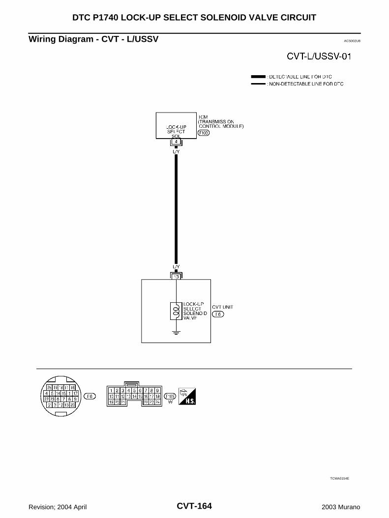
CVT-164
DTC P1740 LOCK-UP SELECT SOLENOID VALVE CIRCUIT
Revision; 2004 April 2003 Murano
Wiring Diagram - CVT - L/USSV ACS002U8
TCWA0154E
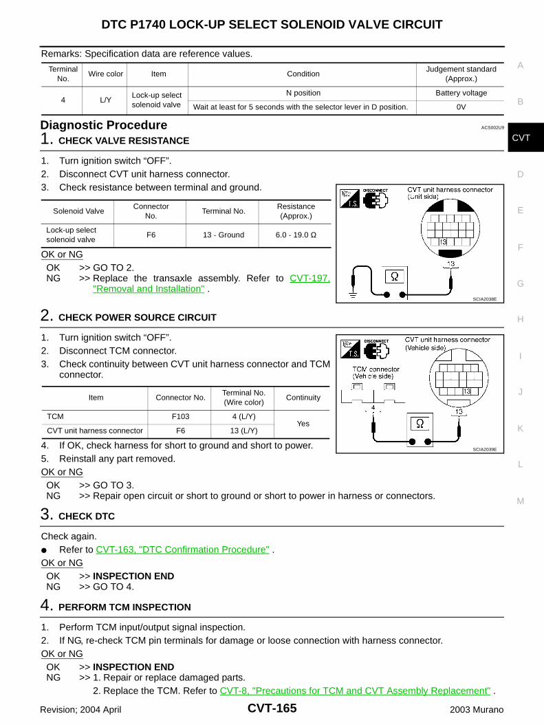
DTC P1740 LOCK-UP SELECT SOLENOID VALVE CIRCUIT
CVT-165
D
E
F
G
H
I
J
K
L
M
A
B
CVT
Revision; 2004 April 2003 Murano
Remarks: Specification data are reference values.
Diagnostic Procedure ACS002U9
1. CHECK VALVE RESISTANCE
1. Turn ignition switch “OFF”.2. Disconnect CVT unit harness connector.3. Check resistance between terminal and ground.
OK or NGOK >> GO TO 2.NG >> Replace the transaxle assembly. Refer to CVT-197,
"Removal and Installation" .
2. CHECK POWER SOURCE CIRCUIT
1. Turn ignition switch “OFF”.2. Disconnect TCM connector.3. Check continuity between CVT unit harness connector and TCM
connector.
4. If OK, check harness for short to ground and short to power.5. Reinstall any part removed.OK or NGOK >> GO TO 3.NG >> Repair open circuit or short to ground or short to power in harness or connectors.
3. CHECK DTC
Check again. Refer to CVT-163, "DTC Confirmation Procedure" .OK or NGOK >> INSPECTION ENDNG >> GO TO 4.
4. PERFORM TCM INSPECTION
1. Perform TCM input/output signal inspection.2. If NG, re-check TCM pin terminals for damage or loose connection with harness connector.OK or NGOK >> INSPECTION END NG >> 1. Repair or replace damaged parts.
2. Replace the TCM. Refer to CVT-8, "Precautions for TCM and CVT Assembly Replacement" .
Terminal No.
Wire color Item ConditionJudgement standard
(Approx.)
4 L/YLock-up select solenoid valve
N position Battery voltage
Wait at least for 5 seconds with the selector lever in D position. 0V
Solenoid ValveConnector
No.Terminal No.
Resistance (Approx.)
Lock-up select solenoid valve
F6 13 - Ground 6.0 - 19.0 Ω
SCIA2038E
Item Connector No.Terminal No. (Wire color)
Continuity
TCM F103 4 (L/Y)Yes
CVT unit harness connector F6 13 (L/Y)
SCIA2039E
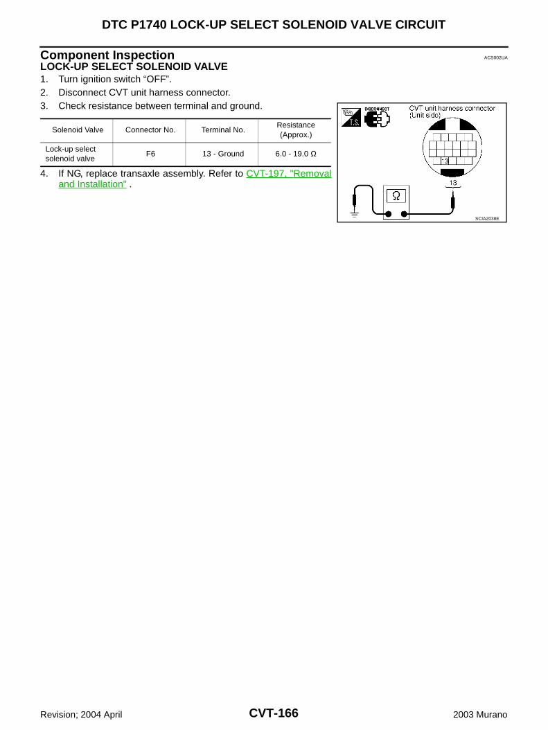
CVT-166
DTC P1740 LOCK-UP SELECT SOLENOID VALVE CIRCUIT
Revision; 2004 April 2003 Murano
Component Inspection ACS002UA
LOCK-UP SELECT SOLENOID VALVE1. Turn ignition switch “OFF”.2. Disconnect CVT unit harness connector.3. Check resistance between terminal and ground.
4. If NG, replace transaxle assembly. Refer to CVT-197, "Removaland Installation" .
Solenoid Valve Connector No. Terminal No. Resistance (Approx.)
Lock-up select solenoid valve
F6 13 - Ground 6.0 - 19.0 Ω
SCIA2038E
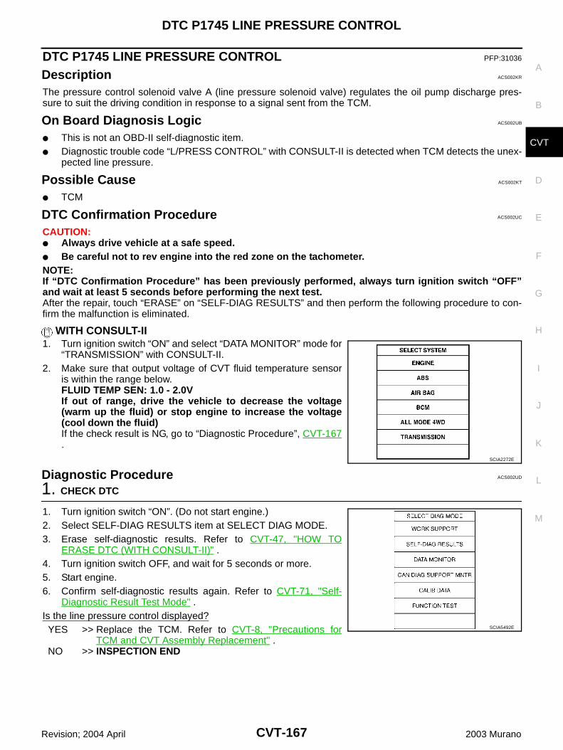
DTC P1745 LINE PRESSURE CONTROL
CVT-167
D
E
F
G
H
I
J
K
L
M
A
B
CVT
Revision; 2004 April 2003 Murano
DTC P1745 LINE PRESSURE CONTROL PFP:31036
Description ACS002KR
The pressure control solenoid valve A (line pressure solenoid valve) regulates the oil pump discharge pres-sure to suit the driving condition in response to a signal sent from the TCM.
On Board Diagnosis Logic ACS002UB
This is not an OBD-II self-diagnostic item. Diagnostic trouble code “L/PRESS CONTROL” with CONSULT-II is detected when TCM detects the unex-
pected line pressure.
Possible Cause ACS002KT
TCM
DTC Confirmation Procedure ACS002UC
CAUTION: Always drive vehicle at a safe speed. Be careful not to rev engine into the red zone on the tachometer.NOTE:If “DTC Confirmation Procedure” has been previously performed, always turn ignition switch “OFF”and wait at least 5 seconds before performing the next test.After the repair, touch “ERASE” on “SELF-DIAG RESULTS” and then perform the following procedure to con-firm the malfunction is eliminated.
WITH CONSULT-II1. Turn ignition switch “ON” and select “DATA MONITOR” mode for
“TRANSMISSION” with CONSULT-II.2. Make sure that output voltage of CVT fluid temperature sensor
is within the range below.FLUID TEMP SEN: 1.0 - 2.0VIf out of range, drive the vehicle to decrease the voltage(warm up the fluid) or stop engine to increase the voltage(cool down the fluid)If the check result is NG, go to “Diagnostic Procedure”, CVT-167.
Diagnostic Procedure ACS002UD
1. CHECK DTC
1. Turn ignition switch “ON”. (Do not start engine.)2. Select SELF-DIAG RESULTS item at SELECT DIAG MODE.3. Erase self-diagnostic results. Refer to CVT-47, "HOW TO
ERASE DTC (WITH CONSULT-II)" .4. Turn ignition switch OFF, and wait for 5 seconds or more.5. Start engine.6. Confirm self-diagnostic results again. Refer to CVT-71, "Self-
Diagnostic Result Test Mode" .Is the line pressure control displayed?YES >> Replace the TCM. Refer to CVT-8, "Precautions for
TCM and CVT Assembly Replacement" .NO >> INSPECTION END
SCIA2272E
SCIA5492E
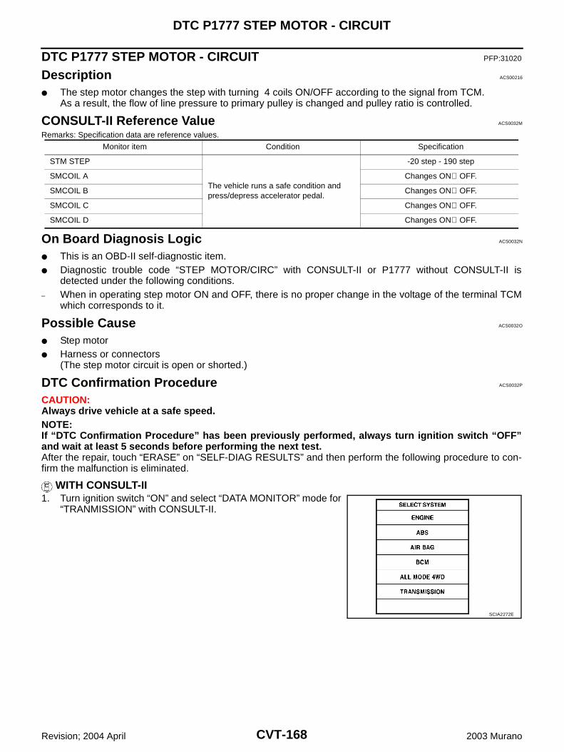
CVT-168
DTC P1777 STEP MOTOR - CIRCUIT
Revision; 2004 April 2003 Murano
DTC P1777 STEP MOTOR - CIRCUIT PFP:31020
Description ACS00216
The step motor changes the step with turning 4 coils ON/OFF according to the signal from TCM.As a result, the flow of line pressure to primary pulley is changed and pulley ratio is controlled.
CONSULT-II Reference Value ACS0032M
Remarks: Specification data are reference values.
On Board Diagnosis Logic ACS0032N
This is an OBD-II self-diagnostic item. Diagnostic trouble code “STEP MOTOR/CIRC” with CONSULT-II or P1777 without CONSULT-II is
detected under the following conditions.– When in operating step motor ON and OFF, there is no proper change in the voltage of the terminal TCM
which corresponds to it.
Possible Cause ACS0032O
Step motor Harness or connectors
(The step motor circuit is open or shorted.)
DTC Confirmation Procedure ACS0032P
CAUTION:Always drive vehicle at a safe speed.NOTE:If “DTC Confirmation Procedure” has been previously performed, always turn ignition switch “OFF”and wait at least 5 seconds before performing the next test.After the repair, touch “ERASE” on “SELF-DIAG RESULTS” and then perform the following procedure to con-firm the malfunction is eliminated.
WITH CONSULT-II1. Turn ignition switch “ON” and select “DATA MONITOR” mode for
“TRANMISSION” with CONSULT-II.
Monitor item Condition Specification
STM STEP
The vehicle runs a safe condition and press/depress accelerator pedal.
-20 step - 190 step
SMCOIL A Changes ON⇔OFF.
SMCOIL B Changes ON⇔OFF.
SMCOIL C Changes ON⇔OFF.
SMCOIL D Changes ON⇔OFF.
SCIA2272E
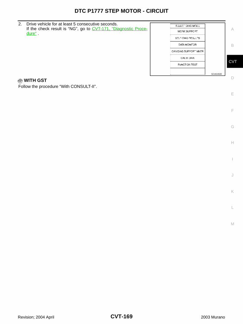
DTC P1777 STEP MOTOR - CIRCUIT
CVT-169
D
E
F
G
H
I
J
K
L
M
A
B
CVT
Revision; 2004 April 2003 Murano
2. Drive vehicle for at least 5 consecutive seconds.If the check result is “NG”, go to CVT-171, "Diagnostic Proce-dure" .
WITH GSTFollow the procedure “With CONSULT-II”.
SCIA5492E
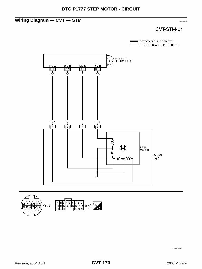
CVT-170
DTC P1777 STEP MOTOR - CIRCUIT
Revision; 2004 April 2003 Murano
Wiring Diagram — CVT — STM ACS00217
TCWA0158E
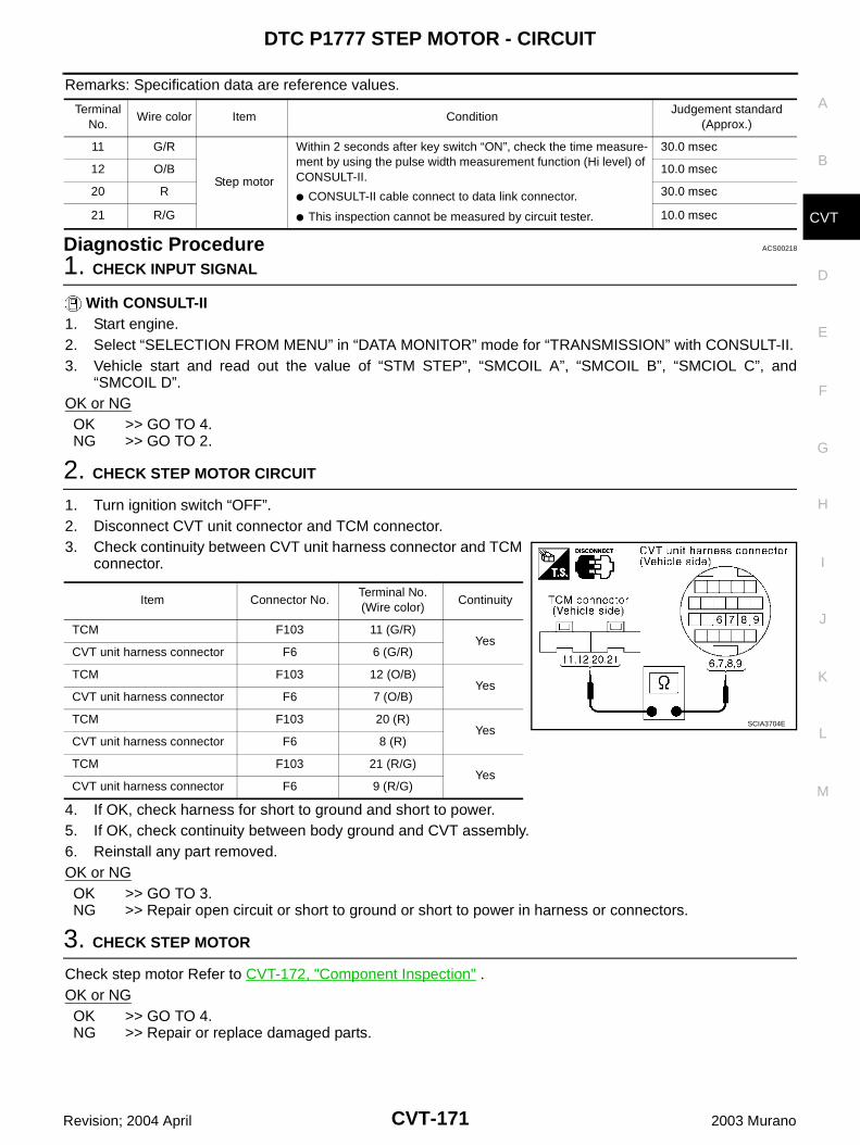
DTC P1777 STEP MOTOR - CIRCUIT
CVT-171
D
E
F
G
H
I
J
K
L
M
A
B
CVT
Revision; 2004 April 2003 Murano
Remarks: Specification data are reference values.
Diagnostic Procedure ACS00218
1. CHECK INPUT SIGNAL
With CONSULT-II1. Start engine.2. Select “SELECTION FROM MENU” in “DATA MONITOR” mode for “TRANSMISSION” with CONSULT-II.3. Vehicle start and read out the value of “STM STEP”, “SMCOIL A”, “SMCOIL B”, “SMCIOL C”, and
“SMCOIL D”.OK or NGOK >> GO TO 4.NG >> GO TO 2.
2. CHECK STEP MOTOR CIRCUIT
1. Turn ignition switch “OFF”.2. Disconnect CVT unit connector and TCM connector.3. Check continuity between CVT unit harness connector and TCM
connector.
4. If OK, check harness for short to ground and short to power.5. If OK, check continuity between body ground and CVT assembly.6. Reinstall any part removed.OK or NGOK >> GO TO 3.NG >> Repair open circuit or short to ground or short to power in harness or connectors.
3. CHECK STEP MOTOR
Check step motor Refer to CVT-172, "Component Inspection" .OK or NGOK >> GO TO 4.NG >> Repair or replace damaged parts.
Terminal No.
Wire color Item ConditionJudgement standard
(Approx.)
11 G/R
Step motor
Within 2 seconds after key switch “ON”, check the time measure-ment by using the pulse width measurement function (Hi level) of CONSULT-II.
CONSULT-II cable connect to data link connector.
This inspection cannot be measured by circuit tester.
30.0 msec
12 O/B 10.0 msec
20 R 30.0 msec
21 R/G 10.0 msec
Item Connector No.Terminal No. (Wire color)
Continuity
TCM F103 11 (G/R)Yes
CVT unit harness connector F6 6 (G/R)
TCM F103 12 (O/B)Yes
CVT unit harness connector F6 7 (O/B)
TCM F103 20 (R)Yes
CVT unit harness connector F6 8 (R)
TCM F103 21 (R/G)Yes
CVT unit harness connector F6 9 (R/G)
SCIA3704E
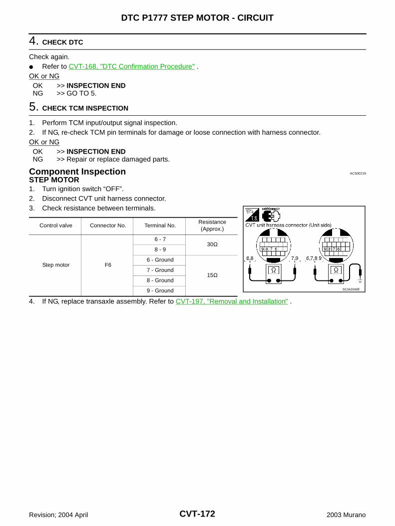
CVT-172
DTC P1777 STEP MOTOR - CIRCUIT
Revision; 2004 April 2003 Murano
4. CHECK DTC
Check again. Refer to CVT-168, "DTC Confirmation Procedure" .OK or NGOK >> INSPECTION ENDNG >> GO TO 5.
5. CHECK TCM INSPECTION
1. Perform TCM input/output signal inspection.2. If NG, re-check TCM pin terminals for damage or loose connection with harness connector.OK or NGOK >> INSPECTION ENDNG >> Repair or replace damaged parts.
Component Inspection ACS00219
STEP MOTOR1. Turn ignition switch “OFF”.2. Disconnect CVT unit harness connector.3. Check resistance between terminals.
4. If NG, replace transaxle assembly. Refer to CVT-197, "Removal and Installation" .
Control valve Connector No. Terminal No.Resistance (Approx.)
Step motor F6
6 - 730Ω
8 - 9
6 - Ground
15Ω7 - Ground
8 - Ground
9 - Ground SCIA2040E
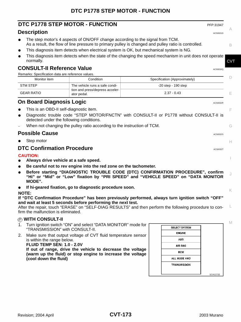
DTC P1778 STEP MOTOR - FUNCTION
CVT-173
D
E
F
G
H
I
J
K
L
M
A
B
CVT
Revision; 2004 April 2003 Murano
DTC P1778 STEP MOTOR - FUNCTION PFP:31947
Description ACS0021D
The step motor's 4 aspects of ON/OFF change according to the signal from TCM.As a result, the flow of line pressure to primary pulley is changed and pulley ratio is controlled.
This diagnosis item detects when electrical system is OK, but mechanical system is NG. This diagnosis item detects when the state of the changing the speed mechanism in unit does not operate
normally.
CONSULT-II Reference Value ACS0032Q
Remarks: Specification data are reference values.
On Board Diagnosis Logic ACS0032R
This is an OBD-II self-diagnostic item. Diagnostic trouble code “STEP MOTOR/FNCTN” with CONSULT-II or P1778 without CONSULT-II is
detected under the following conditions.– When not changing the pulley ratio according to the instruction of TCM.
Possible Cause ACS0032S
Step motor
DTC Confirmation Procedure ACS0032T
CAUTION: Always drive vehicle at a safe speed. Be careful not to rev engine into the red zone on the tachometer. Before starting “DIAGNOSTIC TROUBLE CODE (DTC) CONFIRMATION PROCEDURE”, confirm
“Hi” or “Mid” or “Low” fixation by “PRI SPEED” and “VEHICLE SPEED” on “DATA MONITORMODE”.
If hi-geared fixation, go to diagnostic procedure soon.NOTE:If “DTC Confirmation Procedure” has been previously performed, always turn ignition switch “OFF”and wait at least 5 seconds before performing the next test.After the repair, touch “ERASE” on “SELF-DIAG RESULTS” and then perform the following procedure to con-firm the malfunction is eliminated.
WITH CONSULT-II1. Turn ignition switch “ON” and select “DATA MONITOR” mode for
“TRANSMISSION” with CONSULT-II.2. Make sure that output voltage of CVT fluid temperature sensor
is within the range below.FLUID TEMP SEN: 1.0 - 2.0VIf out of range, drive the vehicle to decrease the voltage(warm up the fluid) or stop engine to increase the voltage(cool down the fluid)
Monitor item Condition Specification (Approximately)
STM STEP The vehicle runs a safe condi-tion and press/depress acceler-ator pedal.
-20 step - 190 step
GEAR RATIO 2.37 - 0.43
SCIA2272E
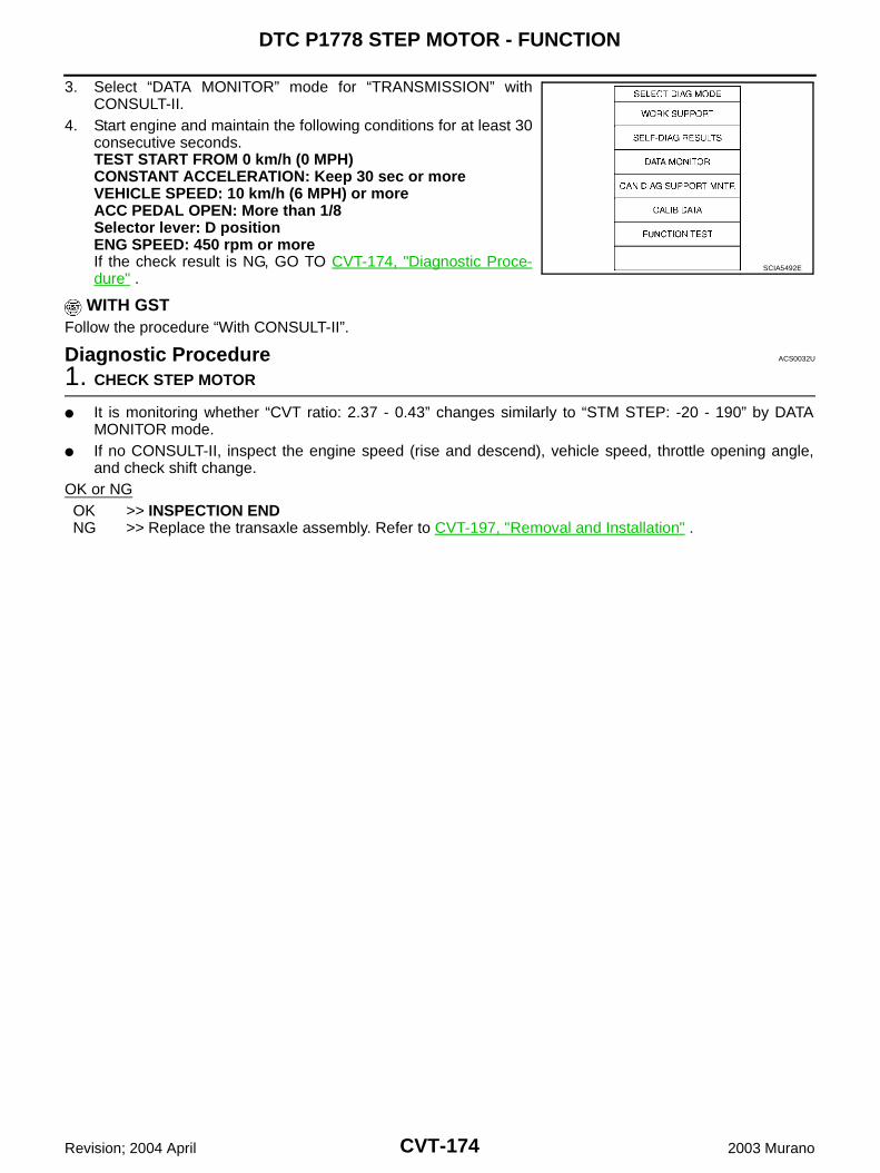
CVT-174
DTC P1778 STEP MOTOR - FUNCTION
Revision; 2004 April 2003 Murano
3. Select “DATA MONITOR” mode for “TRANSMISSION” withCONSULT-II.
4. Start engine and maintain the following conditions for at least 30consecutive seconds.TEST START FROM 0 km/h (0 MPH)CONSTANT ACCELERATION: Keep 30 sec or moreVEHICLE SPEED: 10 km/h (6 MPH) or moreACC PEDAL OPEN: More than 1/8Selector lever: D positionENG SPEED: 450 rpm or moreIf the check result is NG, GO TO CVT-174, "Diagnostic Proce-dure" .
WITH GSTFollow the procedure “With CONSULT-II”.
Diagnostic Procedure ACS0032U
1. CHECK STEP MOTOR
It is monitoring whether “CVT ratio: 2.37 - 0.43” changes similarly to “STM STEP: -20 - 190” by DATAMONITOR mode.
If no CONSULT-II, inspect the engine speed (rise and descend), vehicle speed, throttle opening angle,and check shift change.
OK or NGOK >> INSPECTION ENDNG >> Replace the transaxle assembly. Refer to CVT-197, "Removal and Installation" .
SCIA5492E
SECOND POSITION SWITCH
CVT-175
D
E
F
G
H
I
J
K
L
M
A
B
CVT
Revision; 2004 April 2003 Murano
SECOND POSITION SWITCH PFP:34910
Description ACS0032V
Second position switch is built into CVT control device.When selector lever is in “S” or “L” positions, second position switch turns ON and sends a signal to unifiedmeter and A/C amp. Then signal is transferred to TCM with CAN communications to improve engine brake performance.
CONSULT-II Reference Value ACS00332
Remarks: Specification data are reference values.
Possible Cause ACS0032Y
Harness or connectors(These switch circuits are open or shorted.)
Second position switch (Into control device)
Monitor item Condition Specification
SECOND POS SWSelector lever in “S” position ON
Other than the above (except “L” position) OFF
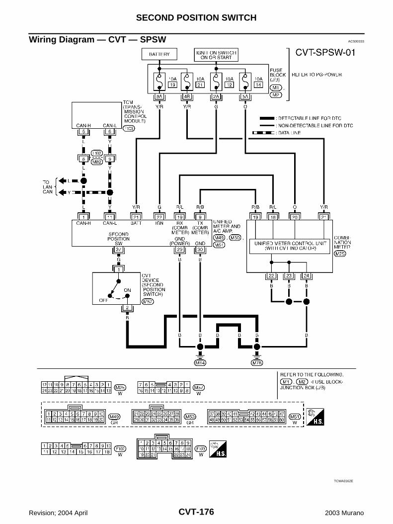
CVT-176
SECOND POSITION SWITCH
Revision; 2004 April 2003 Murano
Wiring Diagram — CVT — SPSW ACS00333
TCWA0162E
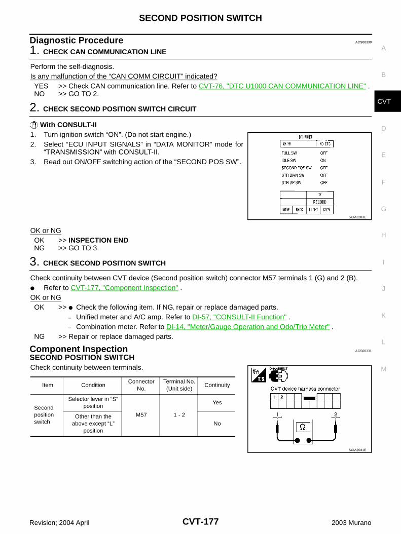
SECOND POSITION SWITCH
CVT-177
D
E
F
G
H
I
J
K
L
M
A
B
CVT
Revision; 2004 April 2003 Murano
Diagnostic Procedure ACS00330
1. CHECK CAN COMMUNICATION LINE
Perform the self-diagnosis.Is any malfunction of the “CAN COMM CIRCUIT” indicated?YES >> Check CAN communication line. Refer to CVT-76, "DTC U1000 CAN COMMUNICATION LINE" .NO >> GO TO 2.
2. CHECK SECOND POSITION SWITCH CIRCUIT
With CONSULT-II1. Turn ignition switch “ON”. (Do not start engine.)2. Select “ECU INPUT SIGNALS” in “DATA MONITOR” mode for
“TRANSMISSION” with CONSULT-II.3. Read out ON/OFF switching action of the “SECOND POS SW”.
OK or NGOK >> INSPECTION ENDNG >> GO TO 3.
3. CHECK SECOND POSITION SWITCH
Check continuity between CVT device (Second position switch) connector M57 terminals 1 (G) and 2 (B). Refer to CVT-177, "Component Inspection" .OK or NGOK >> Check the following item. If NG, repair or replace damaged parts.
– Unified meter and A/C amp. Refer to DI-57, "CONSULT-II Function" .– Combination meter. Refer to DI-14, "Meter/Gauge Operation and Odo/Trip Meter" .
NG >> Repair or replace damaged parts.
Component Inspection ACS00331
SECOND POSITION SWITCHCheck continuity between terminals.
SCIA2283E
Item ConditionConnector
No.Terminal No.(Unit side)
Continuity
Second position switch
Selector lever in “S” position
M57 1 - 2
Yes
Other than the above except “L”
positionNo
SCIA2041E
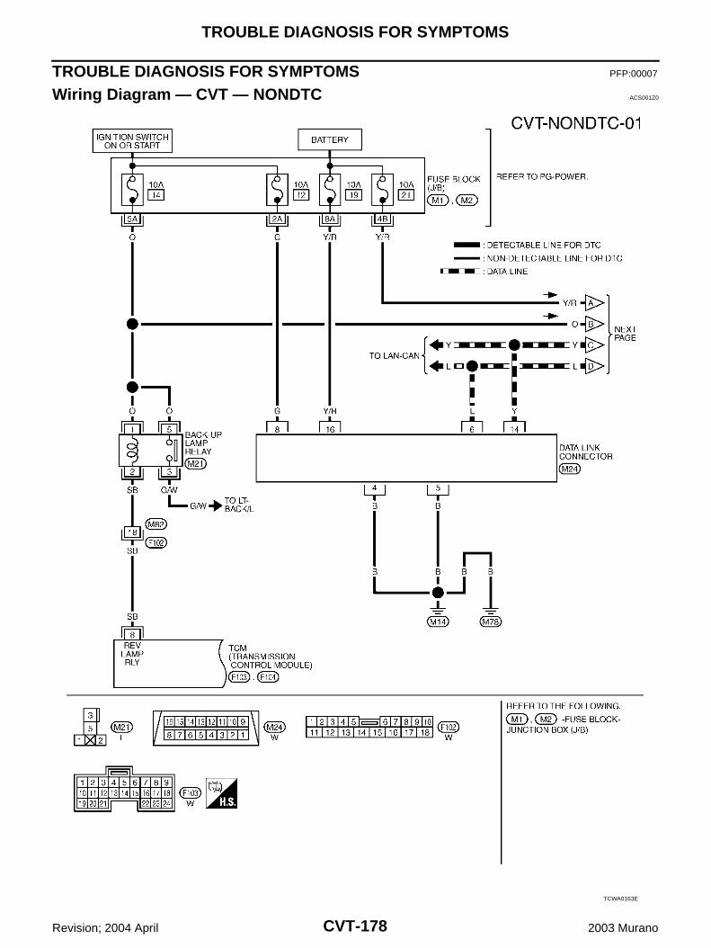
CVT-178
TROUBLE DIAGNOSIS FOR SYMPTOMS
Revision; 2004 April 2003 Murano
TROUBLE DIAGNOSIS FOR SYMPTOMS PFP:00007
Wiring Diagram — CVT — NONDTC ACS001Z0
TCWA0163E
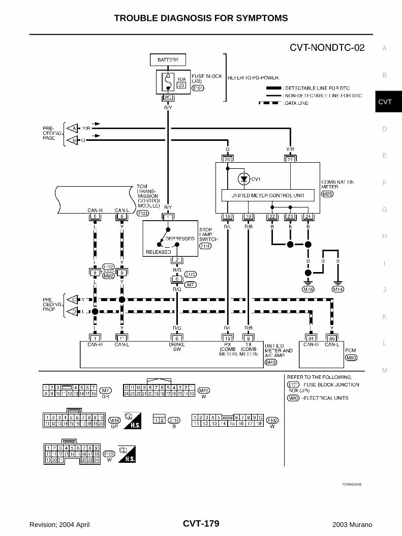
TROUBLE DIAGNOSIS FOR SYMPTOMS
CVT-179
D
E
F
G
H
I
J
K
L
M
A
B
CVT
Revision; 2004 April 2003 Murano
TCWA0164E
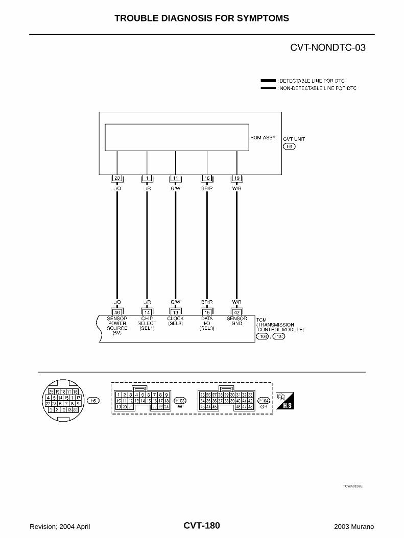
CVT-180
TROUBLE DIAGNOSIS FOR SYMPTOMS
Revision; 2004 April 2003 Murano
TCWA0159E
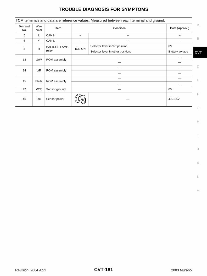
TROUBLE DIAGNOSIS FOR SYMPTOMS
CVT-181
D
E
F
G
H
I
J
K
L
M
A
B
CVT
Revision; 2004 April 2003 Murano
TCM terminals and data are reference values. Measured between each terminal and ground.
Terminal No.
Wire color
Item Condition Data (Approx.)
5 L CAN H – – –
6 Y CAN L – – –
8 RBACK-UP LAMP relay
IGN ONSelector lever in “R” position. 0V
Selector lever in other position. Battery voltage
13 G/W ROM assembly— —
— —
14 L/R ROM assembly— —
— —
15 BR/R ROM assembly— —
— —
42 W/R Sensor ground — 0V
46 L/O Sensor power — 4.5-5.5V
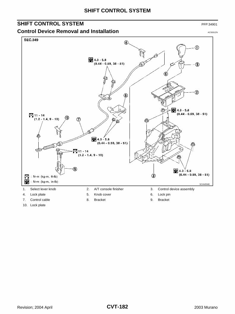
CVT-182
SHIFT CONTROL SYSTEM
Revision; 2004 April 2003 Murano
SHIFT CONTROL SYSTEM PFP:34901
Control Device Removal and Installation ACS001ZN
1. Select lever knob 2. A/T console finisher 3. Control device assembly
4. Lock plate 5. Knob cover 6. Lock pin
7. Control cable 8. Bracket 9. Bracket
10. Lock plate
SCIA4594E
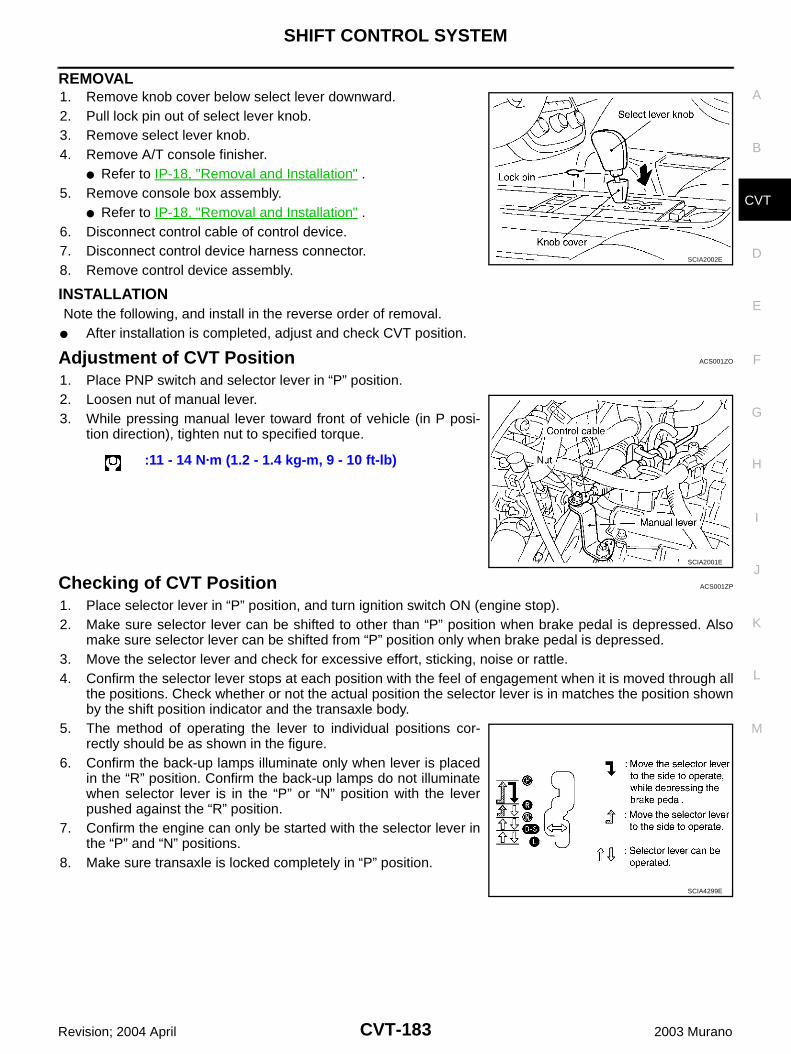
SHIFT CONTROL SYSTEM
CVT-183
D
E
F
G
H
I
J
K
L
M
A
B
CVT
Revision; 2004 April 2003 Murano
REMOVAL1. Remove knob cover below select lever downward.2. Pull lock pin out of select lever knob.3. Remove select lever knob.4. Remove A/T console finisher.
Refer to IP-18, "Removal and Installation" .5. Remove console box assembly.
Refer to IP-18, "Removal and Installation" .6. Disconnect control cable of control device.7. Disconnect control device harness connector.8. Remove control device assembly.
INSTALLATION Note the following, and install in the reverse order of removal. After installation is completed, adjust and check CVT position.
Adjustment of CVT Position ACS001ZO
1. Place PNP switch and selector lever in “P” position.2. Loosen nut of manual lever.3. While pressing manual lever toward front of vehicle (in P posi-
tion direction), tighten nut to specified torque.
Checking of CVT Position ACS001ZP
1. Place selector lever in “P” position, and turn ignition switch ON (engine stop).2. Make sure selector lever can be shifted to other than “P” position when brake pedal is depressed. Also
make sure selector lever can be shifted from “P” position only when brake pedal is depressed.3. Move the selector lever and check for excessive effort, sticking, noise or rattle.4. Confirm the selector lever stops at each position with the feel of engagement when it is moved through all
the positions. Check whether or not the actual position the selector lever is in matches the position shownby the shift position indicator and the transaxle body.
5. The method of operating the lever to individual positions cor-rectly should be as shown in the figure.
6. Confirm the back-up lamps illuminate only when lever is placedin the “R” position. Confirm the back-up lamps do not illuminatewhen selector lever is in the “P” or “N” position with the leverpushed against the “R” position.
7. Confirm the engine can only be started with the selector lever inthe “P” and “N” positions.
8. Make sure transaxle is locked completely in “P” position.
SCIA2002E
:11 - 14 N·m (1.2 - 1.4 kg-m, 9 - 10 ft-lb)
SCIA2001E
SCIA4299E
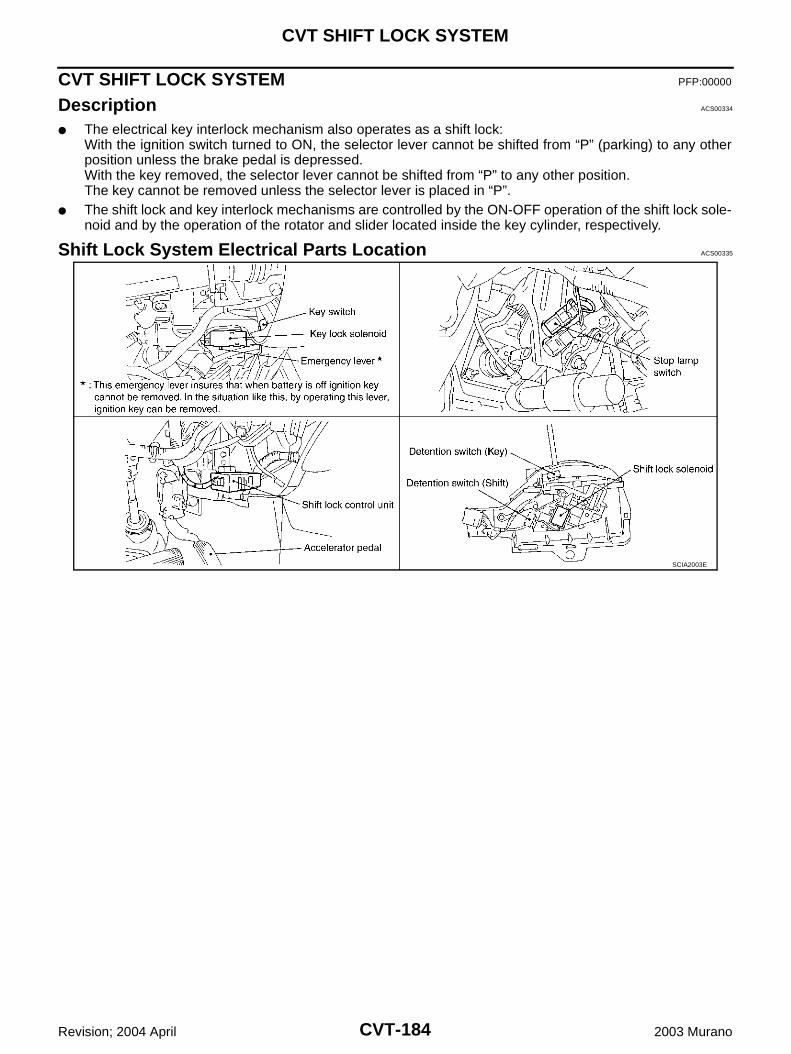
CVT-184
CVT SHIFT LOCK SYSTEM
Revision; 2004 April 2003 Murano
CVT SHIFT LOCK SYSTEM PFP:00000
Description ACS00334
The electrical key interlock mechanism also operates as a shift lock:With the ignition switch turned to ON, the selector lever cannot be shifted from “P” (parking) to any otherposition unless the brake pedal is depressed.With the key removed, the selector lever cannot be shifted from “P” to any other position.The key cannot be removed unless the selector lever is placed in “P”.
The shift lock and key interlock mechanisms are controlled by the ON-OFF operation of the shift lock sole-noid and by the operation of the rotator and slider located inside the key cylinder, respectively.
Shift Lock System Electrical Parts Location ACS00335
SCIA2003E
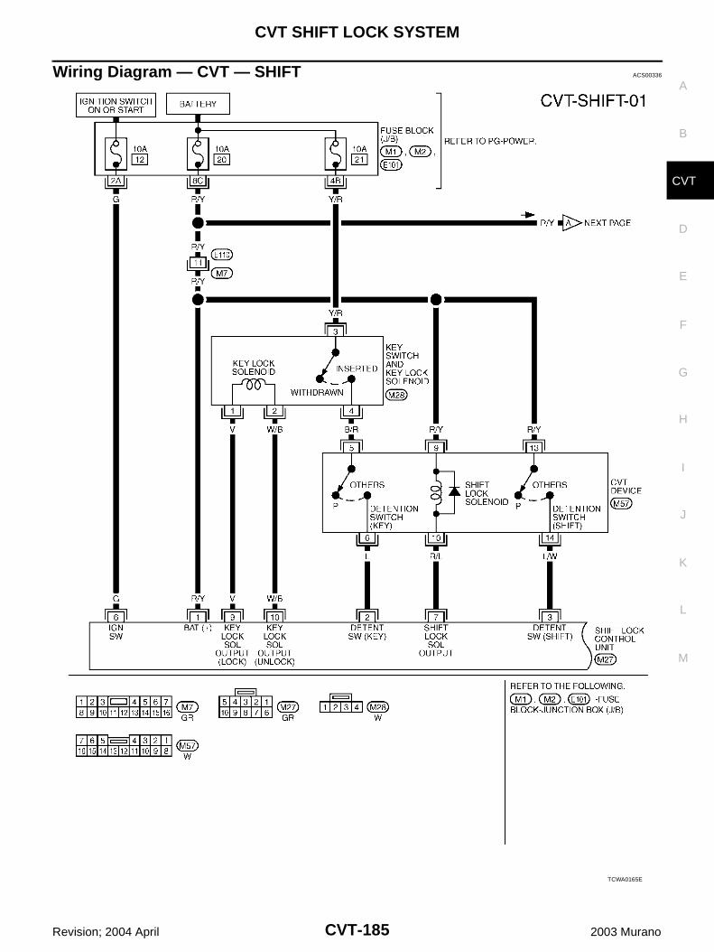
CVT SHIFT LOCK SYSTEM
CVT-185
D
E
F
G
H
I
J
K
L
M
A
B
CVT
Revision; 2004 April 2003 Murano
Wiring Diagram — CVT — SHIFT ACS00336
TCWA0165E
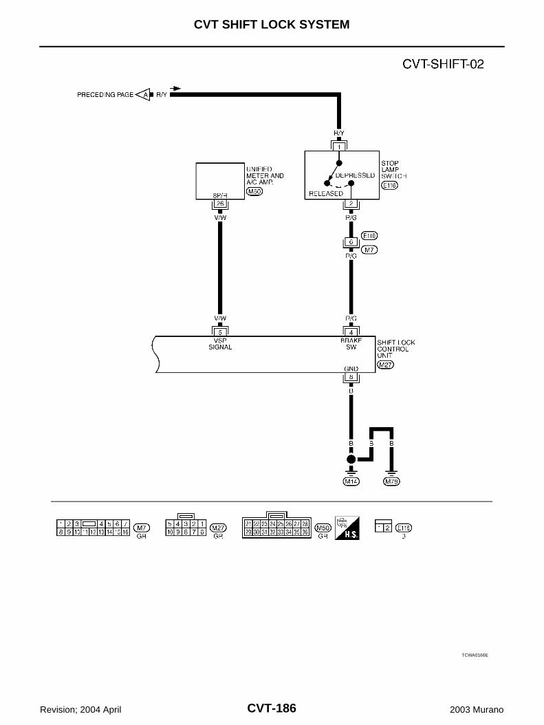
CVT-186
CVT SHIFT LOCK SYSTEM
Revision; 2004 April 2003 Murano
TCWA0166E
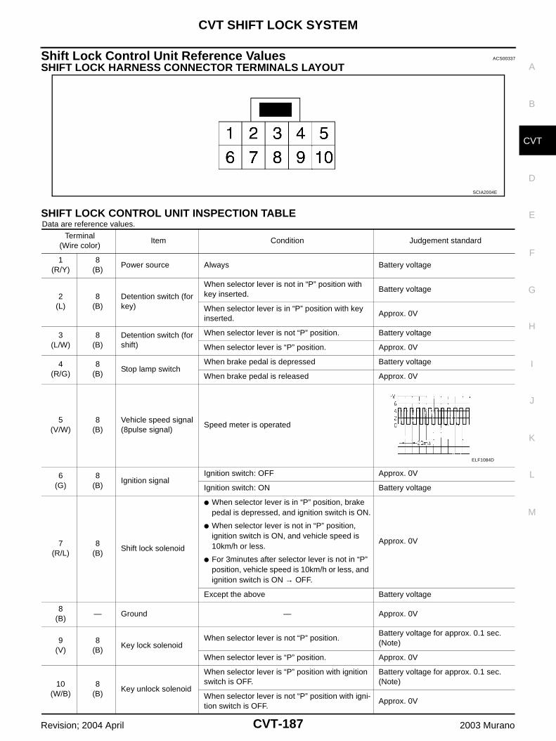
CVT SHIFT LOCK SYSTEM
CVT-187
D
E
F
G
H
I
J
K
L
M
A
B
CVT
Revision; 2004 April 2003 Murano
Shift Lock Control Unit Reference Values ACS00337
SHIFT LOCK HARNESS CONNECTOR TERMINALS LAYOUT
SHIFT LOCK CONTROL UNIT INSPECTION TABLEData are reference values.
SCIA2004E
Terminal(Wire color)
Item Condition Judgement standard
1(R/Y)
8(B)
Power source Always Battery voltage
2(L)
8(B)
Detention switch (for key)
When selector lever is not in “P” position with key inserted.
Battery voltage
When selector lever is in “P” position with key inserted.
Approx. 0V
3(L/W)
8(B)
Detention switch (for shift)
When selector lever is not “P” position. Battery voltage
When selector lever is “P” position. Approx. 0V
4(R/G)
8(B)
Stop lamp switchWhen brake pedal is depressed Battery voltage
When brake pedal is released Approx. 0V
5(V/W)
8(B)
Vehicle speed signal (8pulse signal)
Speed meter is operated
6(G)
8(B)
Ignition signalIgnition switch: OFF Approx. 0V
Ignition switch: ON Battery voltage
7(R/L)
8(B)
Shift lock solenoid
When selector lever is in “P” position, brake pedal is depressed, and ignition switch is ON.
When selector lever is not in “P” position, ignition switch is ON, and vehicle speed is 10km/h or less.
For 3minutes after selector lever is not in “P” position, vehicle speed is 10km/h or less, and ignition switch is ON → OFF.
Approx. 0V
Except the above Battery voltage
8(B)
— Ground — Approx. 0V
9(V)
8(B)
Key lock solenoidWhen selector lever is not “P” position.
Battery voltage for approx. 0.1 sec. (Note)
When selector lever is “P” position. Approx. 0V
10(W/B)
8(B)
Key unlock solenoid
When selector lever is “P” position with ignition switch is OFF.
Battery voltage for approx. 0.1 sec. (Note)
When selector lever is not “P” position with igni-tion switch is OFF.
Approx. 0V
ELF1084D
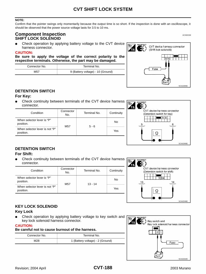
CVT-188
CVT SHIFT LOCK SYSTEM
Revision; 2004 April 2003 Murano
NOTE:Confirm that the pointer swings only momentarily because the output time is so short. If the inspection is done with an oscilloscope, itshould be observed that the power source voltage lasts for 3.5 to 10 ms.
Component Inspection ACS00338
SHIFT LOCK SOLENOID Check operation by applying battery voltage to the CVT device
harness connector.CAUTION:Be sure to apply the voltage of the correct polarity to therespective terminals. Otherwise, the part may be damaged.
DETENTION SWITCHFor Key: Check continuity between terminals of the CVT device harness
connector.
DETENTION SWITCHFor Shift: Check continuity between terminals of the CVT device harness
connector.
KEY LOCK SOLENOIDKey Lock Check operation by applying battery voltage to key switch and
key lock solenoid harness connector.CAUTION:Be careful not to cause burnout of the harness.
Connector No. Terminal No.
M57 9 (Battery voltage) - 10 (Ground)
SCIA2005E
ConditionConnector
No.Terminal No. Continuity
When selector lever is “P” position.
M57 5 - 6
No
When selector lever is not “P” position.
Yes
SCIA2006E
ConditionConnector
No.Terminal No. Continuity
When selector lever is “P” position.
M57 13 - 14
No
When selector lever is not “P” position.
Yes
SCIA2046E
Connector No. Terminal No.
M28 1 (Battery voltage) - 2 (Ground)
SCIA2042E
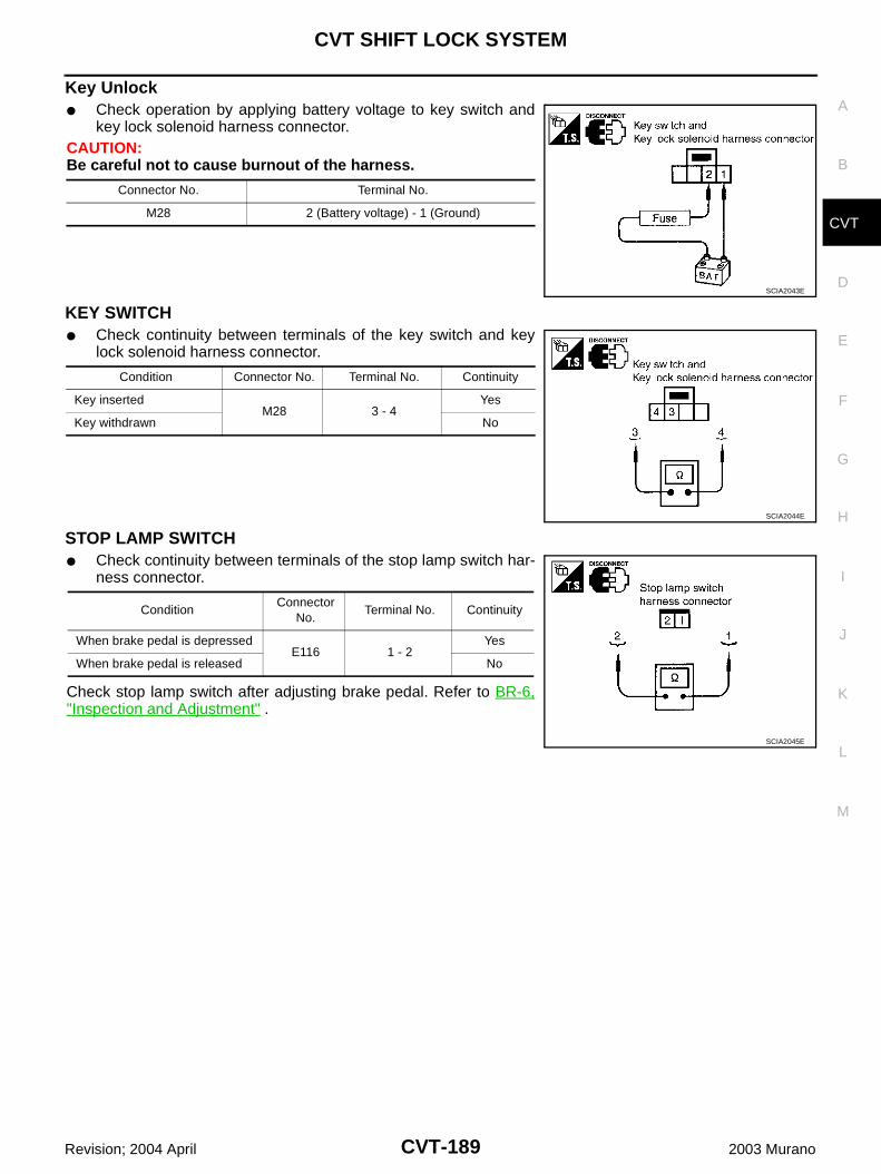
CVT SHIFT LOCK SYSTEM
CVT-189
D
E
F
G
H
I
J
K
L
M
A
B
CVT
Revision; 2004 April 2003 Murano
Key Unlock Check operation by applying battery voltage to key switch and
key lock solenoid harness connector.CAUTION:Be careful not to cause burnout of the harness.
KEY SWITCH Check continuity between terminals of the key switch and key
lock solenoid harness connector.
STOP LAMP SWITCH Check continuity between terminals of the stop lamp switch har-
ness connector.
Check stop lamp switch after adjusting brake pedal. Refer to BR-6,"Inspection and Adjustment" .
Connector No. Terminal No.
M28 2 (Battery voltage) - 1 (Ground)
SCIA2043E
Condition Connector No. Terminal No. Continuity
Key insertedM28 3 - 4
Yes
Key withdrawn No
SCIA2044E
ConditionConnector
No.Terminal No. Continuity
When brake pedal is depressedE116 1 - 2
Yes
When brake pedal is released No
SCIA2045E
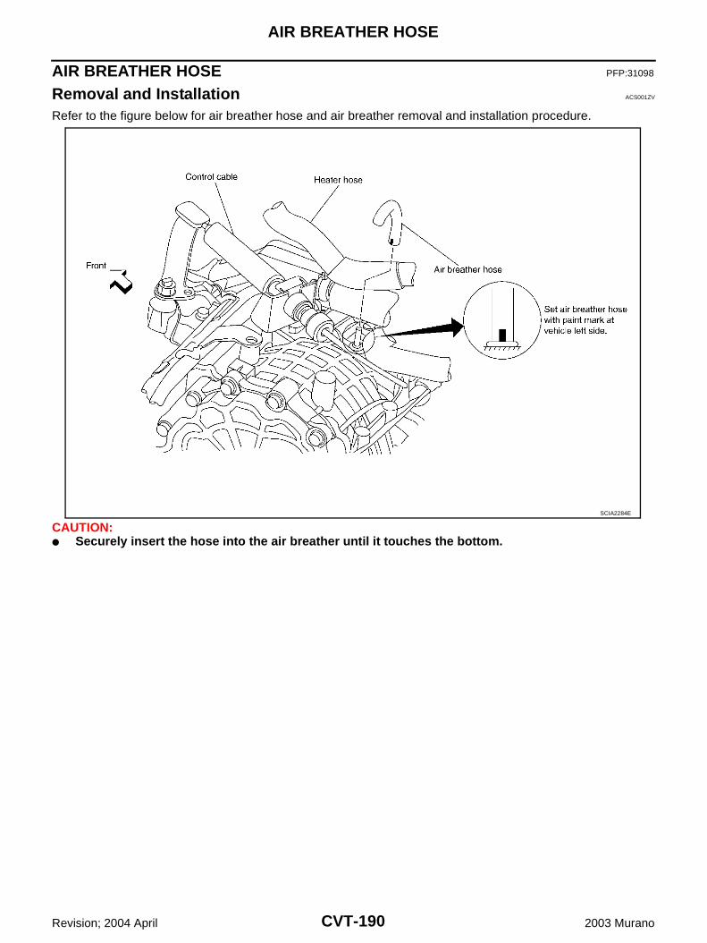
CVT-190
AIR BREATHER HOSE
Revision; 2004 April 2003 Murano
AIR BREATHER HOSE PFP:31098
Removal and Installation ACS001ZV
Refer to the figure below for air breather hose and air breather removal and installation procedure.
CAUTION: Securely insert the hose into the air breather until it touches the bottom.
SCIA2284E
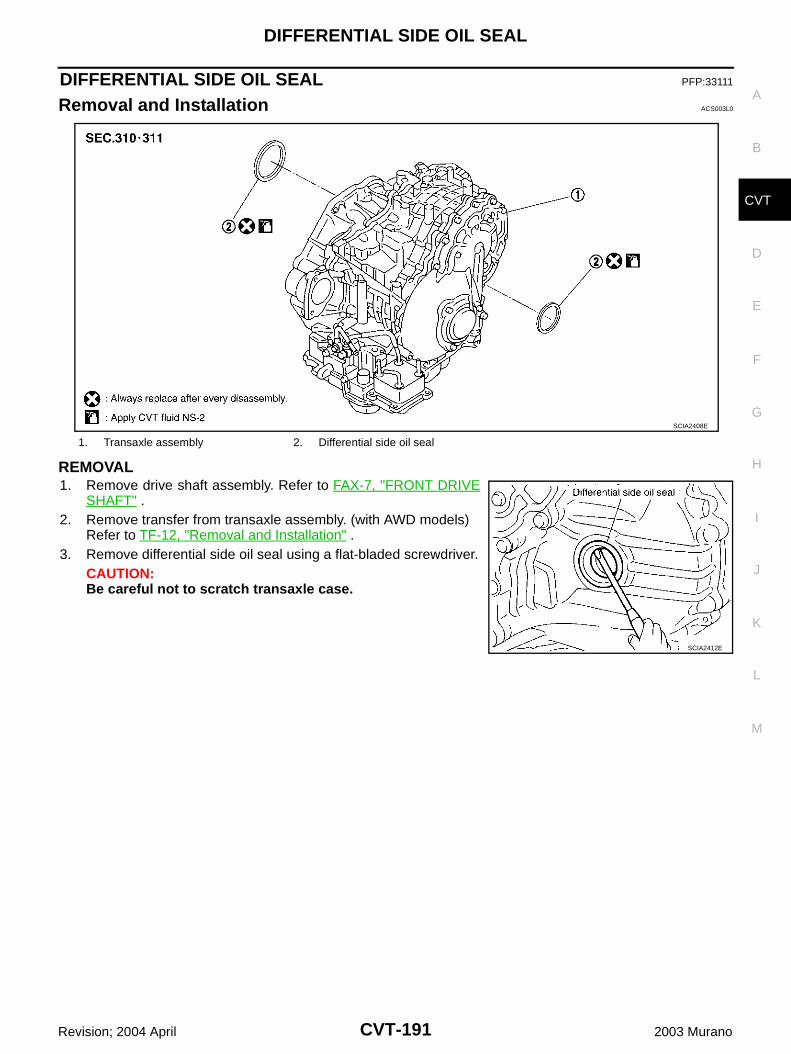
DIFFERENTIAL SIDE OIL SEAL
CVT-191
D
E
F
G
H
I
J
K
L
M
A
B
CVT
Revision; 2004 April 2003 Murano
DIFFERENTIAL SIDE OIL SEAL PFP:33111
Removal and Installation ACS003L0
REMOVAL1. Remove drive shaft assembly. Refer to FAX-7, "FRONT DRIVE
SHAFT" .2. Remove transfer from transaxle assembly. (with AWD models)
Refer to TF-12, "Removal and Installation" .3. Remove differential side oil seal using a flat-bladed screwdriver.
CAUTION:Be careful not to scratch transaxle case.
1. Transaxle assembly 2. Differential side oil seal
SCIA2408E
SCIA2412E
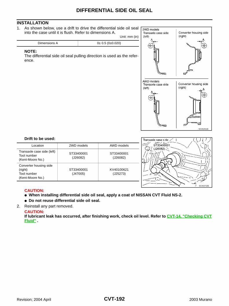
CVT-192
DIFFERENTIAL SIDE OIL SEAL
Revision; 2004 April 2003 Murano
INSTALLATION1. As shown below, use a drift to drive the differential side oil seal
into the case until it is flush. Refer to dimensions A.Unit: mm (in)
NOTE:The differential side oil seal pulling direction is used as the refer-ence.
Drift to be used:
CAUTION: When installing differential side oil seal, apply a coat of NISSAN CVT Fluid NS-2. Do not reuse differential side oil seal.
2. Reinstall any part removed.CAUTION:If lubricant leak has occurred, after finishing work, check oil level. Refer to CVT-14, "Checking CVTFluid" .
Dimensions A 0± 0.5 (0±0.020)
SCIA2411E
Location 2WD models AWD models
Transaxle case side (left)Tool number(Kent-Moore No.)
ST33400001(J26082)
ST33400001(J26082)
Converter housing side (right)Tool number(Kent-Moore No.)
ST33400001(J47005)
KV40100621(J25273)
SCIA3710E
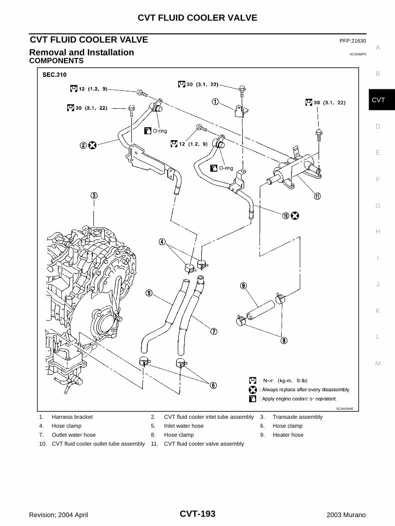
CVT FLUID COOLER VALVE
CVT-193
D
E
F
G
H
I
J
K
L
M
A
B
CVT
Revision; 2004 April 2003 Murano
CVT FLUID COOLER VALVE PFP:21630
Removal and Installation ACS006P5
COMPONENTS
1. Harness bracket 2. CVT fluid cooler inlet tube assembly 3. Transaxle assembly
4. Hose clamp 5. Inlet water hose 6. Hose clamp
7. Outlet water hose 8. Hose clamp 9. Heater hose
10. CVT fluid cooler outlet tube assembly 11. CVT fluid cooler valve assembly
SCIA4344E
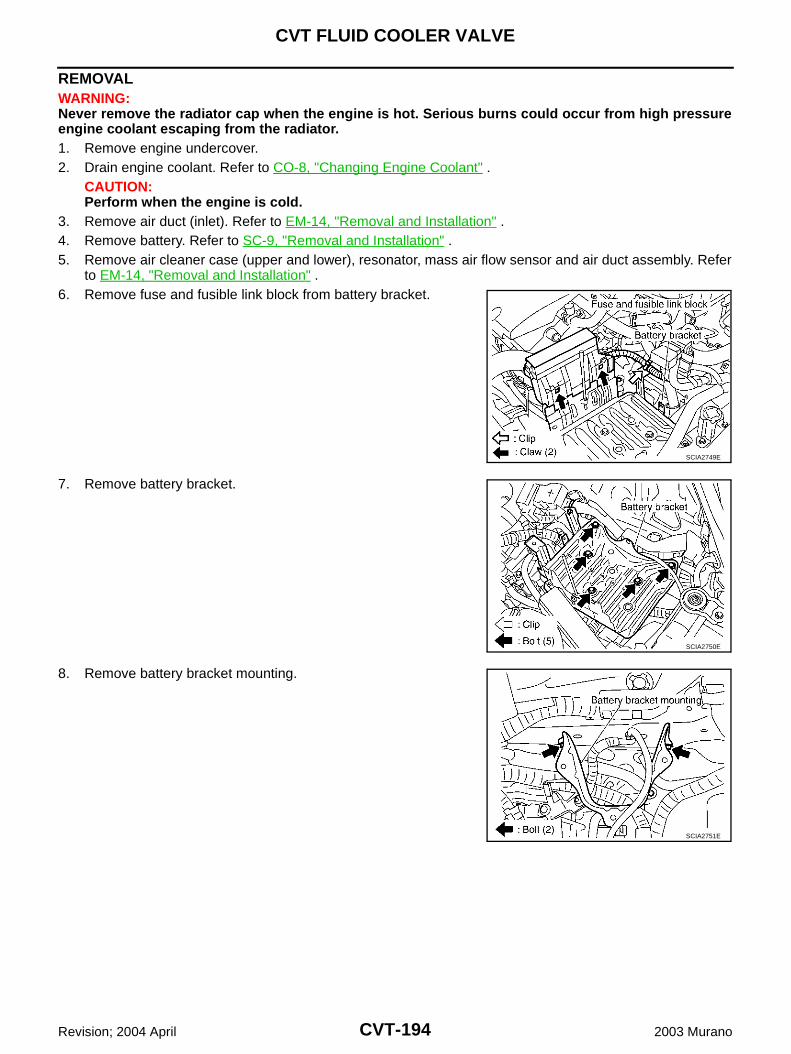
CVT-194
CVT FLUID COOLER VALVE
Revision; 2004 April 2003 Murano
REMOVALWARNING:Never remove the radiator cap when the engine is hot. Serious burns could occur from high pressureengine coolant escaping from the radiator. 1. Remove engine undercover.2. Drain engine coolant. Refer to CO-8, "Changing Engine Coolant" .
CAUTION:Perform when the engine is cold.
3. Remove air duct (inlet). Refer to EM-14, "Removal and Installation" .4. Remove battery. Refer to SC-9, "Removal and Installation" .5. Remove air cleaner case (upper and lower), resonator, mass air flow sensor and air duct assembly. Refer
to EM-14, "Removal and Installation" .6. Remove fuse and fusible link block from battery bracket.
7. Remove battery bracket.
8. Remove battery bracket mounting.
SCIA2749E
SCIA2750E
SCIA2751E
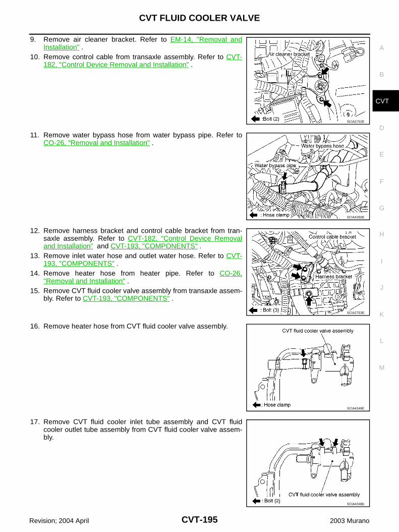
CVT FLUID COOLER VALVE
CVT-195
D
E
F
G
H
I
J
K
L
M
A
B
CVT
Revision; 2004 April 2003 Murano
9. Remove air cleaner bracket. Refer to EM-14, "Removal andInstallation" .
10. Remove control cable from transaxle assembly. Refer to CVT-182, "Control Device Removal and Installation" .
11. Remove water bypass hose from water bypass pipe. Refer toCO-26, "Removal and Installation" .
12. Remove harness bracket and control cable bracket from tran-saxle assembly. Refer to CVT-182, "Control Device Removaland Installation" and CVT-193, "COMPONENTS" .
13. Remove inlet water hose and outlet water hose. Refer to CVT-193, "COMPONENTS" .
14. Remove heater hose from heater pipe. Refer to CO-26,"Removal and Installation" .
15. Remove CVT fluid cooler valve assembly from transaxle assem-bly. Refer to CVT-193, "COMPONENTS" .
16. Remove heater hose from CVT fluid cooler valve assembly.
17. Remove CVT fluid cooler inlet tube assembly and CVT fluidcooler outlet tube assembly from CVT fluid cooler valve assem-bly.
SCIA2752E
SCIA4350E
SCIA2753E
SCIA4349E
SCIA4348E
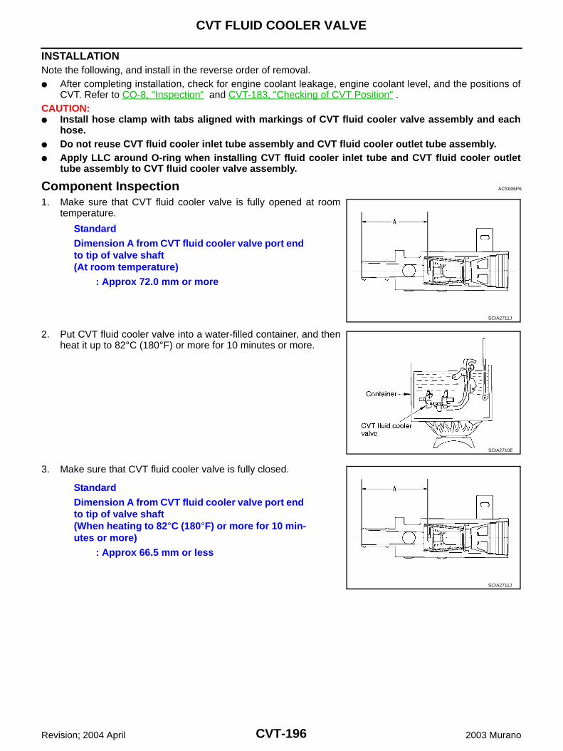
CVT-196
CVT FLUID COOLER VALVE
Revision; 2004 April 2003 Murano
INSTALLATIONNote the following, and install in the reverse order of removal. After completing installation, check for engine coolant leakage, engine coolant level, and the positions of
CVT. Refer to CO-8, "Inspection" and CVT-183, "Checking of CVT Position" .CAUTION: Install hose clamp with tabs aligned with markings of CVT fluid cooler valve assembly and each
hose. Do not reuse CVT fluid cooler inlet tube assembly and CVT fluid cooler outlet tube assembly. Apply LLC around O-ring when installing CVT fluid cooler inlet tube and CVT fluid cooler outlet
tube assembly to CVT fluid cooler valve assembly.
Component Inspection ACS006P6
1. Make sure that CVT fluid cooler valve is fully opened at roomtemperature.
2. Put CVT fluid cooler valve into a water-filled container, and thenheat it up to 82°C (180°F) or more for 10 minutes or more.
3. Make sure that CVT fluid cooler valve is fully closed.
StandardDimension A from CVT fluid cooler valve port end to tip of valve shaft(At room temperature)
: Approx 72.0 mm or more
SCIA2711J
SCIA2710E
StandardDimension A from CVT fluid cooler valve port end to tip of valve shaft(When heating to 82°C (180°F) or more for 10 min-utes or more)
: Approx 66.5 mm or less
SCIA2711J
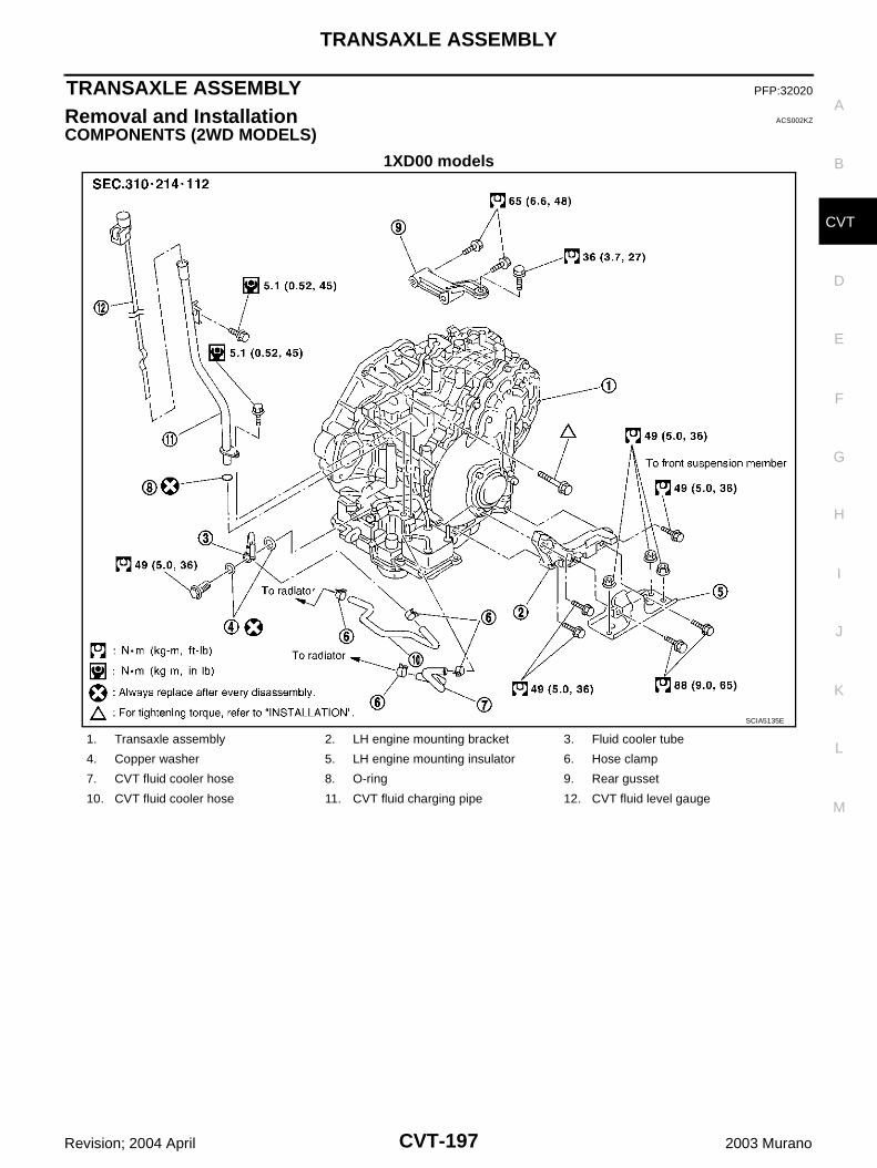
TRANSAXLE ASSEMBLY
CVT-197
D
E
F
G
H
I
J
K
L
M
A
B
CVT
Revision; 2004 April 2003 Murano
TRANSAXLE ASSEMBLY PFP:32020
Removal and Installation ACS002KZ
COMPONENTS (2WD MODELS)
1XD00 models
SCIA5135E
1. Transaxle assembly 2. LH engine mounting bracket 3. Fluid cooler tube
4. Copper washer 5. LH engine mounting insulator 6. Hose clamp
7. CVT fluid cooler hose 8. O-ring 9. Rear gusset
10. CVT fluid cooler hose 11. CVT fluid charging pipe 12. CVT fluid level gauge
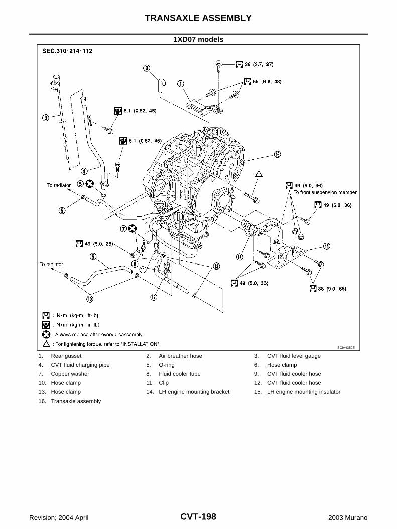
CVT-198
TRANSAXLE ASSEMBLY
Revision; 2004 April 2003 Murano
1XD07 models
SCIA4352E
1. Rear gusset 2. Air breather hose 3. CVT fluid level gauge
4. CVT fluid charging pipe 5. O-ring 6. Hose clamp
7. Copper washer 8. Fluid cooler tube 9. CVT fluid cooler hose
10. Hose clamp 11. Clip 12. CVT fluid cooler hose
13. Hose clamp 14. LH engine mounting bracket 15. LH engine mounting insulator
16. Transaxle assembly
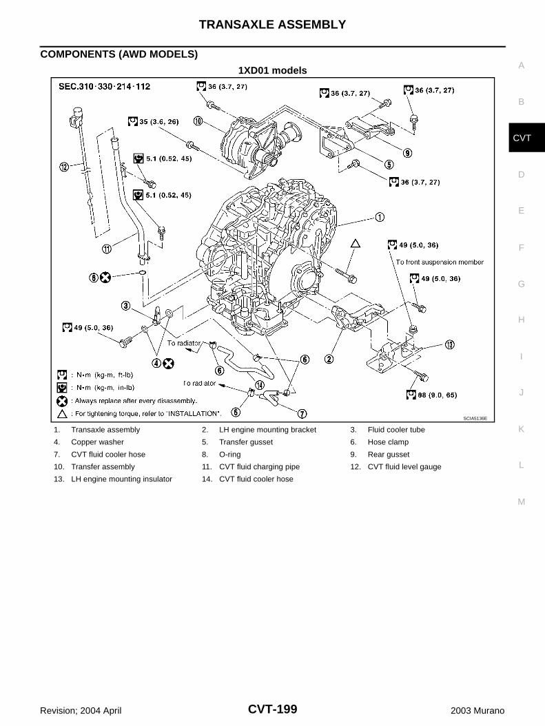
TRANSAXLE ASSEMBLY
CVT-199
D
E
F
G
H
I
J
K
L
M
A
B
CVT
Revision; 2004 April 2003 Murano
COMPONENTS (AWD MODELS)
1XD01 models
SCIA5136E
1. Transaxle assembly 2. LH engine mounting bracket 3. Fluid cooler tube
4. Copper washer 5. Transfer gusset 6. Hose clamp
7. CVT fluid cooler hose 8. O-ring 9. Rear gusset
10. Transfer assembly 11. CVT fluid charging pipe 12. CVT fluid level gauge
13. LH engine mounting insulator 14. CVT fluid cooler hose

CVT-200
TRANSAXLE ASSEMBLY
Revision; 2004 April 2003 Murano
1XD08 models
SCIA4353E
1. Rear gusset 2. Transfer gusset 3. Air breather hose
4. Transfer assembly 5. Front engine mounting bracket 6. CVT fluid level gauge
7. CVT fluid charging pipe 8. O-ring 9. Hose clamp
10. Copper washer 11. Fluid cooler tube 12. CVT fluid cooler hose
13. Hose clamp 14. Clip 15. CVT fluid cooler hose
16. Hose clamp 17. LH engine mounting bracket 18. LH engine mounting insulator
19. Transaxle assembly 20. Rear engine mounting bracket
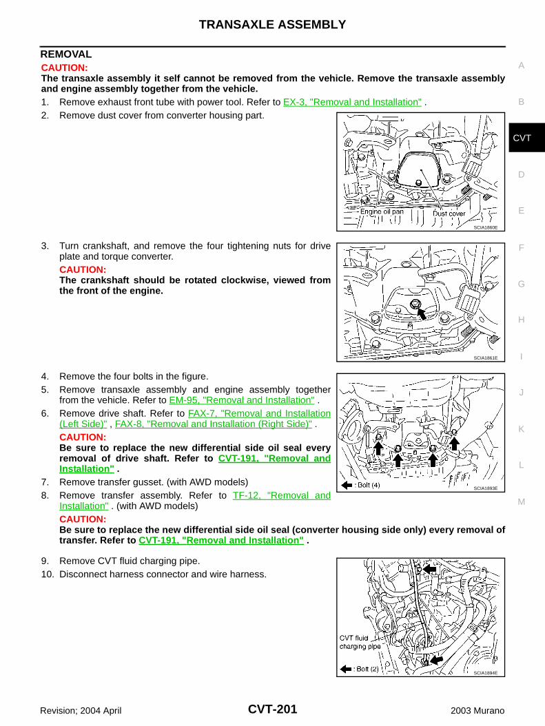
TRANSAXLE ASSEMBLY
CVT-201
D
E
F
G
H
I
J
K
L
M
A
B
CVT
Revision; 2004 April 2003 Murano
REMOVAL CAUTION:The transaxle assembly it self cannot be removed from the vehicle. Remove the transaxle assemblyand engine assembly together from the vehicle. 1. Remove exhaust front tube with power tool. Refer to EX-3, "Removal and Installation" .2. Remove dust cover from converter housing part.
3. Turn crankshaft, and remove the four tightening nuts for driveplate and torque converter.CAUTION:The crankshaft should be rotated clockwise, viewed fromthe front of the engine.
4. Remove the four bolts in the figure.5. Remove transaxle assembly and engine assembly together
from the vehicle. Refer to EM-95, "Removal and Installation" .6. Remove drive shaft. Refer to FAX-7, "Removal and Installation
(Left Side)" , FAX-8, "Removal and Installation (Right Side)" .CAUTION:Be sure to replace the new differential side oil seal everyremoval of drive shaft. Refer to CVT-191, "Removal andInstallation" .
7. Remove transfer gusset. (with AWD models)8. Remove transfer assembly. Refer to TF-12, "Removal and
Installation" . (with AWD models)CAUTION:Be sure to replace the new differential side oil seal (converter housing side only) every removal oftransfer. Refer to CVT-191, "Removal and Installation" .
9. Remove CVT fluid charging pipe.10. Disconnect harness connector and wire harness.
SCIA1860E
SCIA1861E
SCIA1893E
SCIA1894E

CVT-202
TRANSAXLE ASSEMBLY
Revision; 2004 April 2003 Murano
11. Remove POS sensor, from engine assembly. Refer to EM-26,"Removal and Installation" .CAUTION: Do not subject it to impact by dropping or hitting it. Do not disassemble. Do not allow metal filings, etc., to get on the sensor's
front edge magnetic area. Do not place in an area affected by magnetism.
12. Remove starter motor. Refer to SC-16, "Removal and Installa-tion" .
13. Remove CVT fluid cooler valve assembly. (With CVT fluid coolertube assembly and heater hose).
14. Install slinger to transaxle assembly.15. Remove rear gusset.16. Remove LH engine mounting bracket and LH engine mounting
insulator.17. Remove front suspension member from transaxle assembly and
engine assembly. Refer to EM-95, "Removal and Installation" .(with AWD models)
18. Remove transaxle assembly fixing bolts with power tool.
19. Remove transaxle assembly from engine assembly with a hoist. Secure torque converter to prevent it from dropping.
SCIA1895E
SCIA1896E
SCIA1898E
SCIA1868E
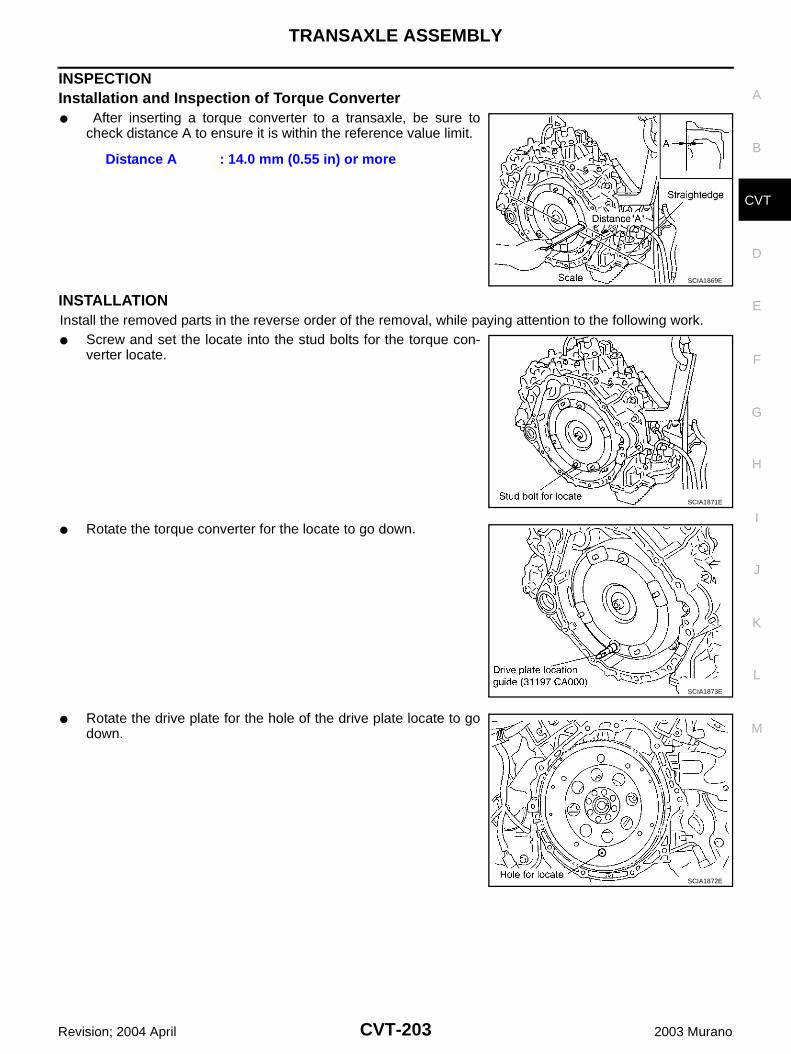
TRANSAXLE ASSEMBLY
CVT-203
D
E
F
G
H
I
J
K
L
M
A
B
CVT
Revision; 2004 April 2003 Murano
INSPECTIONInstallation and Inspection of Torque Converter After inserting a torque converter to a transaxle, be sure to
check distance A to ensure it is within the reference value limit.
INSTALLATIONInstall the removed parts in the reverse order of the removal, while paying attention to the following work. Screw and set the locate into the stud bolts for the torque con-
verter locate.
Rotate the torque converter for the locate to go down.
Rotate the drive plate for the hole of the drive plate locate to godown.
Distance A : 14.0 mm (0.55 in) or more
SCIA1869E
SCIA1871E
SCIA1873E
SCIA1872E
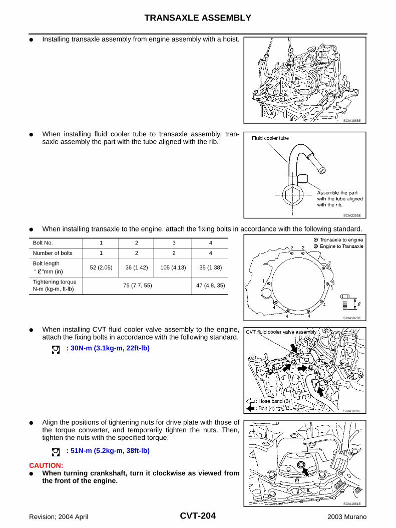
CVT-204
TRANSAXLE ASSEMBLY
Revision; 2004 April 2003 Murano
Installing transaxle assembly from engine assembly with a hoist.
When installing fluid cooler tube to transaxle assembly, tran-saxle assembly the part with the tube aligned with the rib.
When installing transaxle to the engine, attach the fixing bolts in accordance with the following standard.
When installing CVT fluid cooler valve assembly to the engine,attach the fixing bolts in accordance with the following standard.
Align the positions of tightening nuts for drive plate with those ofthe torque converter, and temporarily tighten the nuts. Then,tighten the nuts with the specified torque.
CAUTION: When turning crankshaft, turn it clockwise as viewed from
the front of the engine.
SCIA1868E
SCIA2285E
Bolt No. 1 2 3 4
Number of bolts 1 2 2 4
Bolt length
“ ”mm (in)52 (2.05) 36 (1.42) 105 (4.13) 35 (1.38)
Tightening torqueN-m (kg-m, ft-lb)
75 (7.7, 55) 47 (4.8, 35)
SCIA1870E
: 30N-m (3.1kg-m, 22ft-lb)
SCIA1896E
: 51N-m (5.2kg-m, 38ft-lb)
SCIA1861E
TRANSAXLE ASSEMBLY
CVT-205
D
E
F
G
H
I
J
K
L
M
A
B
CVT
Revision; 2004 April 2003 Murano
When tightening the tightening nuts for the torque converter after fixing the crankshaft pulleybolts, be sure to confirm the tightening torque of the crankshaft pulley mounting bolts.
After converter is installed to drive plate, rotate crankshaft several turns and check to be sure thattransaxle rotates freely without binding.
Install POS sensor. Refer to EM-26, "Removal and Installation" . After completing installation, check for fluid leakage, fluid level, and the positions of CVT. Refer to CVT-14,
"Checking CVT Fluid" , CVT-183, "Adjustment of CVT Position" , CVT-183, "Checking of CVT Position" . When replacing the CVT assembly, erase EEP ROM in TCM. Refer to CVT-8, "Precautions for TCM and
CVT Assembly Replacement" .
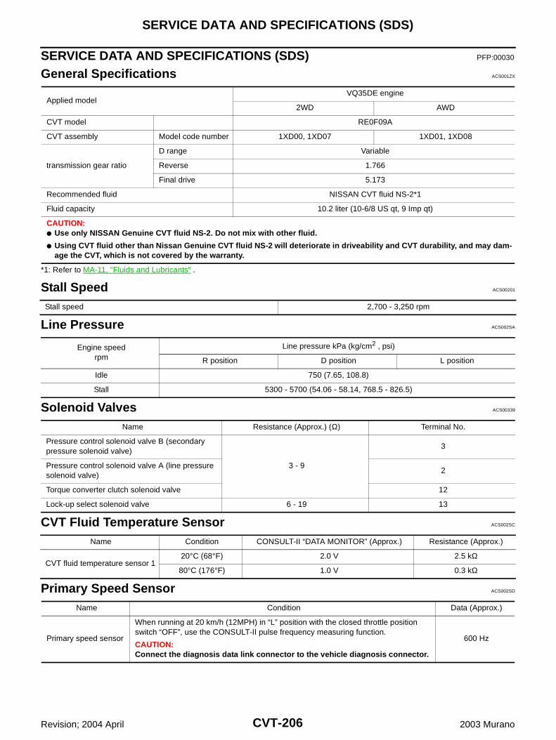
CVT-206
SERVICE DATA AND SPECIFICATIONS (SDS)
Revision; 2004 April 2003 Murano
SERVICE DATA AND SPECIFICATIONS (SDS) PFP:00030
General Specifications ACS001ZX
*1: Refer to MA-11, "Fluids and Lubricants" .
Stall Speed ACS00201
Line Pressure ACS002SA
Solenoid Valves ACS00339
CVT Fluid Temperature Sensor ACS002SC
Primary Speed Sensor ACS002SD
Applied modelVQ35DE engine
2WD AWD
CVT model RE0F09A
CVT assembly Model code number 1XD00, 1XD07 1XD01, 1XD08
transmission gear ratio
D range Variable
Reverse 1.766
Final drive 5.173
Recommended fluid NISSAN CVT fluid NS-2*1
Fluid capacity 10.2 liter (10-6/8 US qt, 9 Imp qt)
CAUTION: Use only NISSAN Genuine CVT fluid NS-2. Do not mix with other fluid.
Using CVT fluid other than Nissan Genuine CVT fluid NS-2 will deteriorate in driveability and CVT durability, and may dam-age the CVT, which is not covered by the warranty.
Stall speed 2,700 - 3,250 rpm
Engine speedrpm
Line pressure kPa (kg/cm2 , psi)
R position D position L position
Idle 750 (7.65, 108.8)
Stall 5300 - 5700 (54.06 - 58.14, 768.5 - 826.5)
Name Resistance (Approx.) (Ω) Terminal No.
Pressure control solenoid valve B (secondary pressure solenoid valve)
3 - 9
3
Pressure control solenoid valve A (line pressure solenoid valve)
2
Torque converter clutch solenoid valve 12
Lock-up select solenoid valve 6 - 19 13
Name Condition CONSULT-II “DATA MONITOR” (Approx.) Resistance (Approx.)
CVT fluid temperature sensor 120°C (68°F) 2.0 V 2.5 kΩ
80°C (176°F) 1.0 V 0.3 kΩ
Name Condition Data (Approx.)
Primary speed sensor
When running at 20 km/h (12MPH) in “L” position with the closed throttle position switch “OFF”, use the CONSULT-II pulse frequency measuring function.
CAUTION:Connect the diagnosis data link connector to the vehicle diagnosis connector.
600 Hz
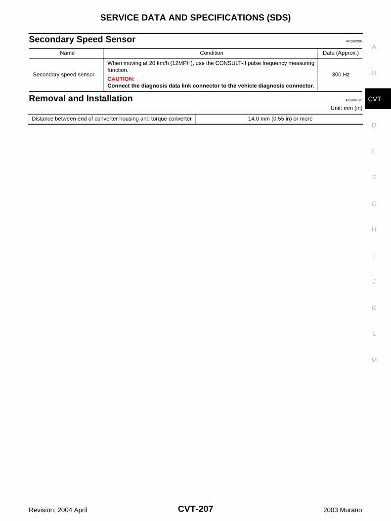
SERVICE DATA AND SPECIFICATIONS (SDS)
CVT-207
D
E
F
G
H
I
J
K
L
M
A
B
CVT
Revision; 2004 April 2003 Murano
Secondary Speed Sensor ACS002SE
Removal and Installation ACS002SG
Unit: mm (in)
Name Condition Data (Approx.)
Secondary speed sensor
When moving at 20 km/h (12MPH), use the CONSULT-II pulse frequency measuring function.
CAUTION:Connect the diagnosis data link connector to the vehicle diagnosis connector.
300 Hz
Distance between end of converter housing and torque converter 14.0 mm (0.55 in) or more
CVT-208
SERVICE DATA AND SPECIFICATIONS (SDS)
Revision; 2004 April 2003 Murano