
CVD ServerRoomDesignGuide AUG13
89
Server Room TECHNOLOGY DESIGN GUIDE August 2013
-
Upload
wawan-ymci-kupang -
Category
Documents
-
view
72 -
download
5
description
server room
Transcript of CVD ServerRoomDesignGuide AUG13
Server Roomtechnology deSign guide
August 2013
table of contents
Table of Contents
Preface ........................................................................................................................................1
CVD Navigator .............................................................................................................................2use cases .................................................................................................................................. 2Scope ......................................................................................................................................... 2Proficiency .................................................................................................................................. 2
Introduction .................................................................................................................................3technology use cases ............................................................................................................... 5
use case: deploy Server Room lAn in central and Remote locations ................................. 5use case: Secure Server Room Resources with cisco ASA .................................................. 5
design overview ......................................................................................................................... 6Server Room ethernet lAn ................................................................................................... 6Server Room Security ........................................................................................................... 7
Server Room Ethernet LAN ..........................................................................................................8design overview ......................................................................................................................... 8deployment details .................................................................................................................... 9
configuring the Server Room ethernet lAn ........................................................................... 9
Server Room Security ................................................................................................................21design overview ....................................................................................................................... 21
Security topology design .................................................................................................... 22Security Policy development ................................................................................................ 23
deployment details ................................................................................................................... 24configuring Firewall connectivity for the Server Room ......................................................... 25configuring the Server Room Firewall .................................................................................. 29configuring Firewall high Availability ..................................................................................... 34evaluating and deploying Firewall Security Policy ................................................................. 36deploying Firewall intrusion Prevention Systems (iPS) .......................................................... 47
Appendix A: Product List ...........................................................................................................61
Appendix B: Configuration Examples .........................................................................................62cisco catalyst 3750-X Switch Stack ......................................................................................... 62cisco ASA 5500-X Firewall-Primary ......................................................................................... 72cisco ASA 5500-X iPS-Primary ................................................................................................ 77cisco ASA 5500-X Firewall-Secondary .................................................................................... 79cisco ASA 5500-X iPS-Secondary........................................................................................... 85
Preface August 20131
Prefacecisco Validated designs (cVds) provide the framework for systems design based on common use cases or current engineering system priorities. they incorporate a broad set of technologies, features, and applications to address customer needs. cisco engineers have comprehensively tested and documented each cVd in order to ensure faster, more reliable, and fully predictable deployment.
cVds include two guide types that provide tested and validated design and deployment details:
• Technology design guides provide deployment details, information about validated products andsoftware, and best practices for specific types of technology.
• Solution design guides integrate or reference existing cVds, but also include product features andfunctionality across cisco products and may include information about third-party integration.
Both cVd types provide a tested starting point for cisco partners or customers to begin designing and deploying systems using their own setup and configuration.
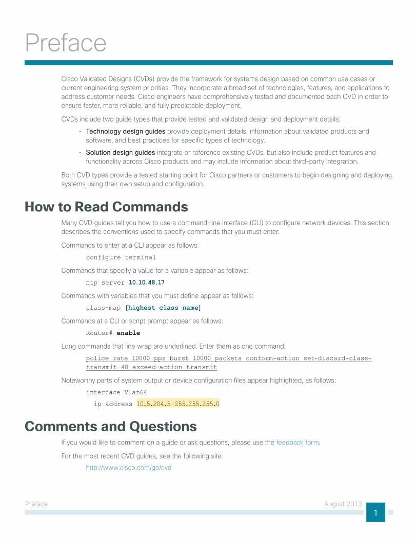
How to Read CommandsMany cVd guides tell you how to use a command-line interface (cli) to configure network devices. this section describes the conventions used to specify commands that you must enter.
commands to enter at a cli appear as follows:
configure terminal
commands that specify a value for a variable appear as follows:
ntp server 10.10.48.17
commands with variables that you must define appear as follows:
class-map [highest class name]
commands at a cli or script prompt appear as follows:
Router# enable
long commands that line wrap are underlined. enter them as one command:
police rate 10000 pps burst 10000 packets conform-action set-discard-class-transmit 48 exceed-action transmit
noteworthy parts of system output or device configuration files appear highlighted, as follows:
interface Vlan64
ip address 10.5.204.5 255.255.255.0
Comments and Questionsif you would like to comment on a guide or ask questions, please use the feedback form.
For the most recent cVd guides, see the following site:
http://www.cisco.com/go/cvd
cVd navigator August 20132
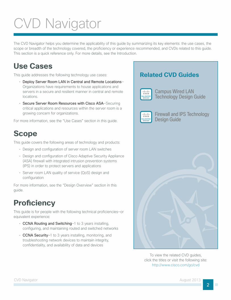
cVd navigatorthe cVd navigator helps you determine the applicability of this guide by summarizing its key elements: the use cases, the scope or breadth of the technology covered, the proficiency or experience recommended, and cVds related to this guide. this section is a quick reference only. For more details, see the introduction.
Use Casesthis guide addresses the following technology use cases:
• Deploy Server Room LAN in Central and Remote Locations—organizations have requirements to house applications and servers in a secure and resilient manner in central and remote locations.
• Secure Server Room Resources with Cisco ASA—Securing critical applications and resources within the server room is a growing concern for organizations.
For more information, see the “use cases” section in this guide.
Scopethis guide covers the following areas of technology and products:
• design and configuration of server room lAn switches
• design and configuration of cisco Adaptive Security Appliance (ASA) firewall with integrated intrusion prevention systems (iPS) in order to protect servers and applications
• Server room lAn quality of service (QoS) design and configuration
For more information, see the “design overview” section in this guide.
Proficiencythis guide is for people with the following technical proficiencies—or equivalent experience:
• CCNA Routing and Switching—1 to 3 years installing, configuring, and maintaining routed and switched networks
• CCNA Security—1 to 3 years installing, monitoring, and troubleshooting network devices to maintain integrity, confidentiality, and availability of data and devices
Related CVD Guides
Campus Wired LANTechnology Design GuideVALIDATED
DESIGN
VALIDATEDDESIGN
Firewall and IPS TechnologyDesign Guide
to view the related cVd guides, click the titles or visit the following site:
http://www.cisco.com/go/cvd
introduction August 20133
introductionthis guide is designed to provide a growing organization its first formal foundation for centralizing up to 24 physical servers in a secure and resilient environment. it can also be used to provide a server room deployment for a regional site or in-country location for a larger organization. this guide is a prescriptive design based on the campus Wired lAn design guide so that you can use the layer 3 services of your cisco Validated design (cVd) lAn distribution layer for routing traffic to and from the iP subnets in the server room.
cVd incorporates lAn, WAn, wireless, security, WAn optimization, and unified communication technologies tested together as a solution. the cVd server room is part of the larger cVd design and incorporates the same equipment, processes, and procedures as the cVd campus design in order to provide seamless extension of service for the servers and appliances in the server room.
this guide, Server Room Design Guide, includes the following chapters:
• “Server Room ethernet lAn” includes guidance for the configuration of server ports on the switches, VlAn usage and trunking, resiliency, and connectivity to the lAn distribution layer or collapsed lAn core.
• “Server Room Security” focuses on the deployment of firewalls and intrusion prevention systems (iPS) in order to help protect the information assets of your organization.
• the appendices provides the complete list of products used in the lab testing of this design, software revisions used on the products in the system, a summary of changes to this guide since it was last published, and configuration examples for the products used.
As organizations scale beyond the server room to data centers with many application servers and larger storage environments, the data center design guide provides a methodology for a smooth transition.
introduction August 20134
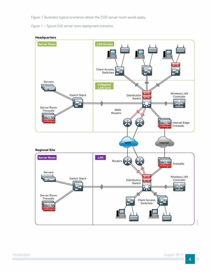
Figure 1 illustrates typical scenarios where the cVd server room would apply.
Figure 1 - Typical CVD server room deployment scenarios
30
22
DistributionSwitch
Wireless LANController
DistributionSwitch
Wireless LANController
Headquarters
Regional Site
CollapsedLAN Core
LAN Access
Server Room
Server Room
LAN
WANRouters
WAN
Routers
Internet
Internet EdgeFirewalls
Firewalls
Server RoomFirewalls
Servers
Switch Stack
Server RoomFirewalls
Servers
Client AccessSwitches
Client AccessSwitches
Switch Stack
introduction August 20135
Technology Use Casesthe Server Room Design Guide is designed to address two primary use cases:
• deploy Server Room lAn for central and remote locations
• Secure server room resources with cisco ASA
the design illustrates how to cleanly integrate network security capabilities such as firewall and intrusion prevention, while protecting areas of the network housing critical server and storage resources. the architecture provides the flexibility to secure specific portions of the server room or insert firewall capability between tiers of a multi-tier application, according to the security policy agreed upon by the organization.
Use Case: Deploy Server Room LAN in Central and Remote Locationsorganizations and businesses often begin their it practices with application servers sitting under desks or in closets with switches—and perhaps some storage tapes for ad hoc backups stacked on top. As the organization grows and its reliance on data grows, so does the need to provide a more stable environment for its critical applications. Whether it is the fear of an outage delaying productivity, data loss that could harm the perception of an organization, or regulatory compliance, the it person or group is forced to build a more suitable environment.
the server room represents the first move into a serious it environment onsite with the business. An example environment will have controlled cooling and power, two to three equipment racks for application servers, supporting network connectivity, and a small backup system.
Also, many organizations have large remote-site locations that might house hundreds of employees and require local processing for communication services, file sharing, and low-latency access to information. organizations extending their presence to a global reach often require regional offices located in a foreign country in order to focus on geographic and business requirements. these remote-site locations often require an it environment for their local servers in order to provide high availability and security for the applications being used. the Server Room Design Guide provides a foundation for housing those applications and servers in a secure and resilient manner.
this guide enables the following server room capabilities:
• deployment of up to 24 physical servers in central or remote locations
• establishment of resilient 1ge server connections using dual server access layer switches
• deployment of layer 2 switches using cisco StackWise Plus, 802.1Q trunks, link Aggregation control Protocol (lAcP), and quality of service (QoS) for server access environments
Use Case: Secure Server Room Resources with Cisco ASAWith communication and commerce in the world becoming increasingly internet-based, network security quickly becomes a primary concern in a growing organization. often organizations will begin by securing their internet edge connection, considering the internal network a trusted entity. however, an internet firewall is only one component of building security into the network infrastructure.
Frequently, threats to an organization’s data may come from within the internal network. this may come in the form of onsite vendors, contaminated employee laptops, or existing servers that have already become compromised and may be used as a platform to launch further attacks. With the centralized repository of the organization’s most critical data typically being the data center, security is no longer considered an optional component of a complete data center architecture plan.
the server room of a small organization contains some of the organization’s most valuable assets. customer and personnel records, financial data, email stores, and intellectual property must be maintained in a secure environment to ensure confidentiality and availability. Additionally, portions of networks in specific business
introduction August 20136
sectors may be subject to industry or government regulations that mandate specific security controls in order to protect customer or client information. Some regional offices may require a server room for in-country operation where the need to protect customer and business information dictates local security measures.
this guide enables the following server room capabilities:
• deployment of cisco ASA Firewalls in active-standby configuration
• deployment of a basic firewall security policy to protect server room resources
• deployment of an integrated cisco ASA intrusion Prevention System (iPS) in an in-line configuration
• deployment of in-line iPS security policy to protect server room resources
Design Overviewthe chapters in this guide describe a design that enables communications across the organization. this section provides architectural guidance specific to the network components or services you need to deploy.
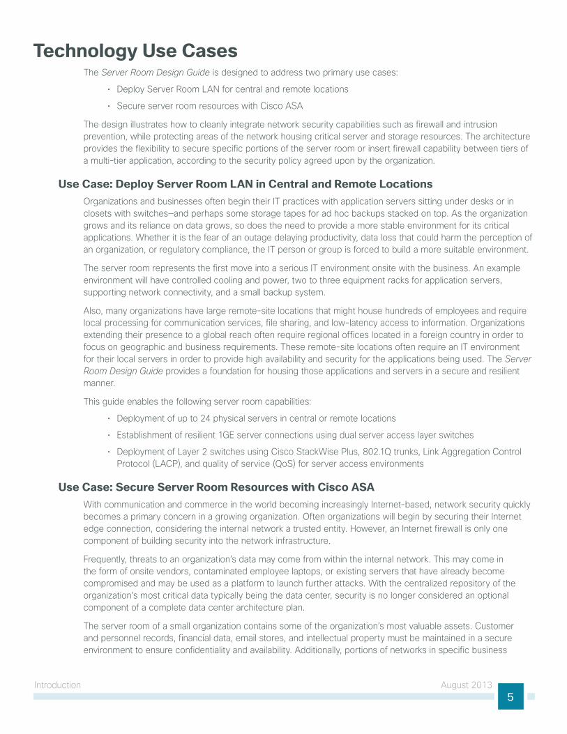
Server Room Ethernet LAN the server room switches provide network connectivity for servers and appliances that offer network and user services to a variety of devices in the network. the server room design has two product lines to choose from: cisco catalyst 3750-X Series and cisco catalyst 3560-X Series switches. cisco catalyst 3750-X Series offers flexible port density and server port connection speeds from 10-Mb ethernet to 1-gigabit ethernet. With a cisco catalyst 3750-X Series switch stack, you can build in fault tolerance by dual-homing servers to the server room and dual-homing the server room to the lAn distribution layer with redundant gigabit ethernet or 10-gigabit ethernet links in an etherchannel. cisco catalyst 3750-X Series provides platform resilience when stacked through cisco StackWise Plus, which allows the control plane for the server room ethernet switches to reside on either of the catalyst 3750-X Series switches and fail over in the event of a failure. cisco StackPower on the catalyst 3750-X Series switch provides the ability to spread the power load over multiple power supplies in each chassis for diversity and resilience. the cisco catalyst 3560-X Series switch offers a lower-cost option for applications where ethernet lAn switch resiliency is not a priority.
Figure 2 - Resilience in the server room design
30
13
ServersSwitchStack
DistributionSwitch
Both the server room and the client lAn access methods connect devices to the network; the difference between the two methods that changes the switch model is the requirement in the lAn access for Power over ethernet (Poe). Although Poe-capable devices are not typical in the server room, using Poe-capable switches offers a benefit worth considering: the minor initial cost savings of a non-Poe switch may not be worth the benefits of using the same switch across multiple modules of your local lAn. Although configurations differ between lAn access switches and server room switches, the ability to use a single switch type between multiple modules can lower operational costs by allowing for simpler sparing and management, as well as provide a better chance of reuse as the organization grows.
introduction August 20137
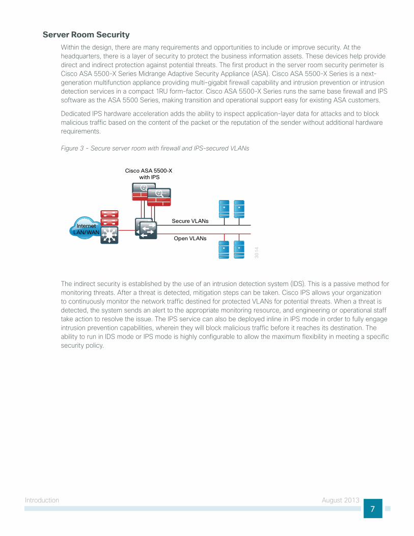
Server Room Security Within the design, there are many requirements and opportunities to include or improve security. At the headquarters, there is a layer of security to protect the business information assets. these devices help provide direct and indirect protection against potential threats. the first product in the server room security perimeter is cisco ASA 5500-X Series Midrange Adaptive Security Appliance (ASA). cisco ASA 5500-X Series is a next-generation multifunction appliance providing multi-gigabit firewall capability and intrusion prevention or intrusion detection services in a compact 1Ru form-factor. cisco ASA 5500-X Series runs the same base firewall and iPS software as the ASA 5500 Series, making transition and operational support easy for existing ASA customers.
dedicated iPS hardware acceleration adds the ability to inspect application-layer data for attacks and to block malicious traffic based on the content of the packet or the reputation of the sender without additional hardware requirements.
Figure 3 - Secure server room with firewall and IPS-secured VLANs
30
14
Secure VLANs
Open VLANs
Cisco ASA 5500-X with IPS
InternetLAN/WAN
the indirect security is established by the use of an intrusion detection system (idS). this is a passive method for monitoring threats. After a threat is detected, mitigation steps can be taken. cisco iPS allows your organization to continuously monitor the network traffic destined for protected VlAns for potential threats. When a threat is detected, the system sends an alert to the appropriate monitoring resource, and engineering or operational staff take action to resolve the issue. the iPS service can also be deployed inline in iPS mode in order to fully engage intrusion prevention capabilities, wherein they will block malicious traffic before it reaches its destination. the ability to run in idS mode or iPS mode is highly configurable to allow the maximum flexibility in meeting a specific security policy.
Server Room ethernet lAn August 20138
Server Room ethernet lAn
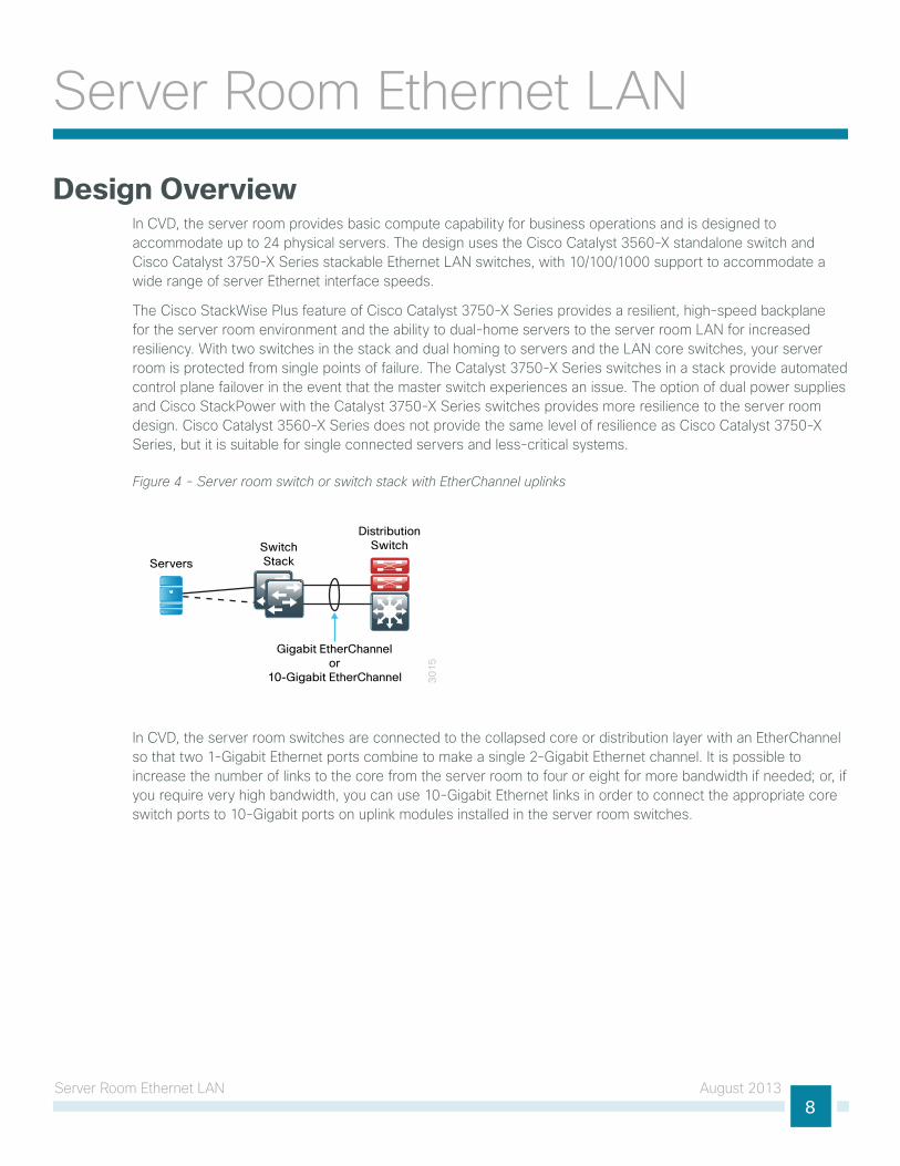
Design Overviewin cVd, the server room provides basic compute capability for business operations and is designed to accommodate up to 24 physical servers. the design uses the cisco catalyst 3560-X standalone switch and cisco catalyst 3750-X Series stackable ethernet lAn switches, with 10/100/1000 support to accommodate a wide range of server ethernet interface speeds.
the cisco StackWise Plus feature of cisco catalyst 3750-X Series provides a resilient, high-speed backplane for the server room environment and the ability to dual-home servers to the server room lAn for increased resiliency. With two switches in the stack and dual homing to servers and the lAn core switches, your server room is protected from single points of failure. the catalyst 3750-X Series switches in a stack provide automated control plane failover in the event that the master switch experiences an issue. the option of dual power supplies and cisco StackPower with the catalyst 3750-X Series switches provides more resilience to the server room design. cisco catalyst 3560-X Series does not provide the same level of resilience as cisco catalyst 3750-X Series, but it is suitable for single connected servers and less-critical systems.
Figure 4 - Server room switch or switch stack with EtherChannel uplinks
30
15
ServersSwitchStack
Gigabit EtherChannelor
10-Gigabit EtherChannel
DistributionSwitch
in cVd, the server room switches are connected to the collapsed core or distribution layer with an etherchannel so that two 1-gigabit ethernet ports combine to make a single 2-gigabit ethernet channel. it is possible to increase the number of links to the core from the server room to four or eight for more bandwidth if needed; or, if you require very high bandwidth, you can use 10-gigabit ethernet links in order to connect the appropriate core switch ports to 10-gigabit ports on uplink modules installed in the server room switches.
Server Room ethernet lAn August 20139
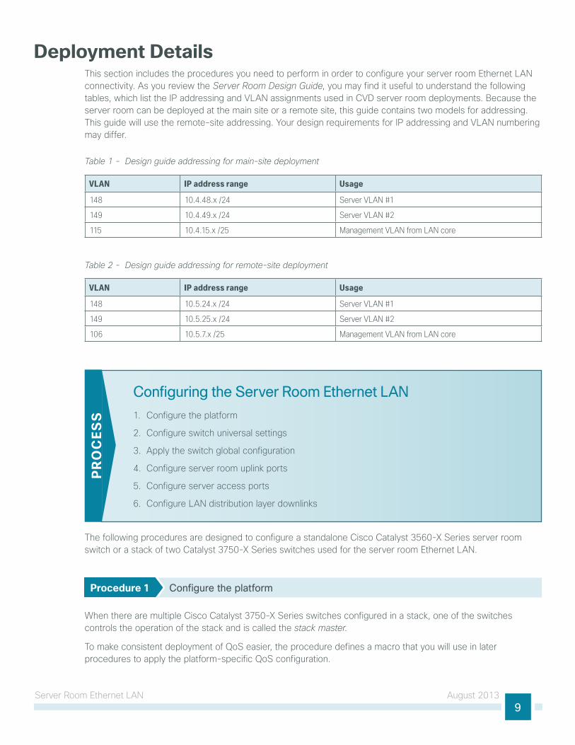
Deployment Details this section includes the procedures you need to perform in order to configure your server room ethernet lAn connectivity. As you review the Server Room Design Guide, you may find it useful to understand the following tables, which list the iP addressing and VlAn assignments used in cVd server room deployments. Because the server room can be deployed at the main site or a remote site, this guide contains two models for addressing. this guide will use the remote-site addressing. your design requirements for iP addressing and VlAn numbering may differ.
Table 1 - Design guide addressing for main-site deployment
VLAN IP address range Usage
148 10.4.48.x /24 Server VLAN #1
149 10.4.49.x /24 Server VLAN #2
115 10.4.15.x /25 Management VLAN from LAN core
Table 2 - Design guide addressing for remote-site deployment
VLAN IP address range Usage
148 10.5.24.x /24 Server VLAN #1
149 10.5.25.x /24 Server VLAN #2
106 10.5.7.x /25 Management VLAN from LAN core
Configuring the Server Room Ethernet LAN
1. configure the platform
2. configure switch universal settings
3. Apply the switch global configuration
4. configure server room uplink ports
5. configure server access ports
6. configure lAn distribution layer downlinks
PR
OC
ESS
the following procedures are designed to configure a standalone cisco catalyst 3560-X Series server room switch or a stack of two catalyst 3750-X Series switches used for the server room ethernet lAn.
Procedure 1 Configure the platform
When there are multiple cisco catalyst 3750-X Series switches configured in a stack, one of the switches controls the operation of the stack and is called the stack master.
to make consistent deployment of QoS easier, the procedure defines a macro that you will use in later procedures to apply the platform-specific QoS configuration.
Server Room ethernet lAn August 201310
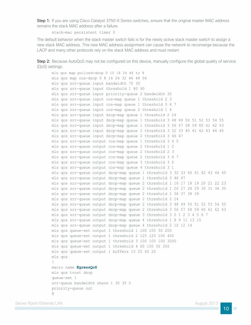
Step 1: if you are using cisco catalyst 3750-X Series switches, ensure that the original master MAc address remains the stack MAc address after a failure.
stack-mac persistent timer 0
the default behavior when the stack master switch fails is for the newly active stack master switch to assign a new stack MAc address. this new MAc address assignment can cause the network to reconverge because the lAcP and many other protocols rely on the stack MAc address and must restart.
Step 2: Because AutoQoS may not be configured on this device, manually configure the global quality of service (QoS) settings.
mls qos map policed-dscp 0 10 18 24 46 to 8 mls qos map cos-dscp 0 8 16 24 32 46 48 56 mls qos srr-queue input bandwidth 70 30 mls qos srr-queue input threshold 1 80 90 mls qos srr-queue input priority-queue 2 bandwidth 30 mls qos srr-queue input cos-map queue 1 threshold 2 3 mls qos srr-queue input cos-map queue 1 threshold 3 6 7 mls qos srr-queue input cos-map queue 2 threshold 1 4 mls qos srr-queue input dscp-map queue 1 threshold 2 24 mls qos srr-queue input dscp-map queue 1 threshold 3 48 49 50 51 52 53 54 55 mls qos srr-queue input dscp-map queue 1 threshold 3 56 57 58 59 60 61 62 63 mls qos srr-queue input dscp-map queue 2 threshold 3 32 33 40 41 42 43 44 45 mls qos srr-queue input dscp-map queue 2 threshold 3 46 47 mls qos srr-queue output cos-map queue 1 threshold 3 4 5 mls qos srr-queue output cos-map queue 2 threshold 1 2 mls qos srr-queue output cos-map queue 2 threshold 2 3 mls qos srr-queue output cos-map queue 2 threshold 3 6 7 mls qos srr-queue output cos-map queue 3 threshold 3 0 mls qos srr-queue output cos-map queue 4 threshold 3 1 mls qos srr-queue output dscp-map queue 1 threshold 3 32 33 40 41 42 43 44 45 mls qos srr-queue output dscp-map queue 1 threshold 3 46 47 mls qos srr-queue output dscp-map queue 2 threshold 1 16 17 18 19 20 21 22 23 mls qos srr-queue output dscp-map queue 2 threshold 1 26 27 28 29 30 31 34 35 mls qos srr-queue output dscp-map queue 2 threshold 1 36 37 38 39 mls qos srr-queue output dscp-map queue 2 threshold 2 24 mls qos srr-queue output dscp-map queue 2 threshold 3 48 49 50 51 52 53 54 55 mls qos srr-queue output dscp-map queue 2 threshold 3 56 57 58 59 60 61 62 63 mls qos srr-queue output dscp-map queue 3 threshold 3 0 1 2 3 4 5 6 7 mls qos srr-queue output dscp-map queue 4 threshold 1 8 9 11 13 15 mls qos srr-queue output dscp-map queue 4 threshold 2 10 12 14 mls qos queue-set output 1 threshold 1 100 100 50 200 mls qos queue-set output 1 threshold 2 125 125 100 400 mls qos queue-set output 1 threshold 3 100 100 100 3200 mls qos queue-set output 1 threshold 4 60 150 50 200 mls qos queue-set output 1 buffers 15 25 40 20 mls qos !macro name EgressQoS mls qos trust dscp queue-set 1 srr-queue bandwidth share 1 30 35 5 priority-queue out @
Server Room ethernet lAn August 201311
Procedure 2 Configure switch universal settings
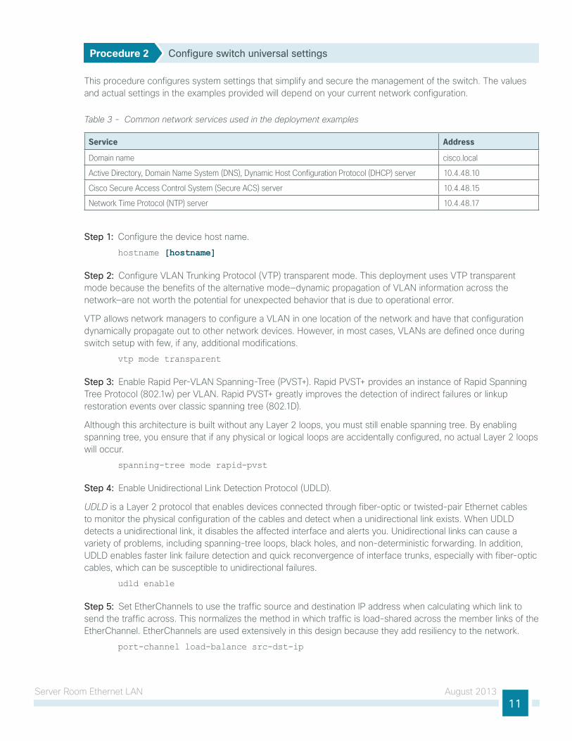
this procedure configures system settings that simplify and secure the management of the switch. the values and actual settings in the examples provided will depend on your current network configuration.
Table 3 - Common network services used in the deployment examples
Service Address
Domain name cisco.local
Active Directory, Domain Name System (DNS), Dynamic Host Configuration Protocol (DHCP) server 10.4.48.10
Cisco Secure Access Control System (Secure ACS) server 10.4.48.15
Network Time Protocol (NTP) server 10.4.48.17
Step 1: configure the device host name.
hostname [hostname]
Step 2: configure VlAn trunking Protocol (VtP) transparent mode. this deployment uses VtP transparent mode because the benefits of the alternative mode—dynamic propagation of VlAn information across the network—are not worth the potential for unexpected behavior that is due to operational error.
VtP allows network managers to configure a VlAn in one location of the network and have that configuration dynamically propagate out to other network devices. however, in most cases, VlAns are defined once during switch setup with few, if any, additional modifications.
vtp mode transparent
Step 3: enable Rapid Per-VlAn Spanning-tree (PVSt+). Rapid PVSt+ provides an instance of Rapid Spanning tree Protocol (802.1w) per VlAn. Rapid PVSt+ greatly improves the detection of indirect failures or linkup restoration events over classic spanning tree (802.1d).
Although this architecture is built without any layer 2 loops, you must still enable spanning tree. By enabling spanning tree, you ensure that if any physical or logical loops are accidentally configured, no actual layer 2 loops will occur.
spanning-tree mode rapid-pvst
Step 4: enable unidirectional link detection Protocol (udld).
UDLD is a layer 2 protocol that enables devices connected through fiber-optic or twisted-pair ethernet cables to monitor the physical configuration of the cables and detect when a unidirectional link exists. When udld detects a unidirectional link, it disables the affected interface and alerts you. unidirectional links can cause a variety of problems, including spanning-tree loops, black holes, and non-deterministic forwarding. in addition, udld enables faster link failure detection and quick reconvergence of interface trunks, especially with fiber-optic cables, which can be susceptible to unidirectional failures.
udld enable
Step 5: Set etherchannels to use the traffic source and destination iP address when calculating which link to send the traffic across. this normalizes the method in which traffic is load-shared across the member links of the etherchannel. etherchannels are used extensively in this design because they add resiliency to the network.
port-channel load-balance src-dst-ip
Server Room ethernet lAn August 201312
Step 6: configure dnS for host lookup.
At the command line of a cisco ioS device, it is helpful to be able to type a domain name instead of the iP address for a destination.
ip name-server 10.4.48.10
Step 7: configure device management protocols.
Secure httP (httPS) and Secure Shell (SSh) Protocol are secure replacements for the httP and telnet protocols. they use SSl and transport layer Security (tlS) in order to provide device authentication and data encryption.
the SSh and httPS protocols enable secure management of the lAn device. Both protocols are encrypted for privacy, and the unsecure protocols—telnet and httP—are turned off.
Specify the transport preferred none command on vty lines. this prevents errant connection attempts from the cli prompt. Without this command, if the iP name server is unreachable, long timeout delays may occur for mistyped commands.
ip domain-name cisco.localip ssh version 2
no ip http server
ip http secure-server
line vty 0 15
transport input ssh
transport preferred none
Step 8: enable Simple network Management Protocol (SnMP), and then configure SnMPv2c both for a read-only and a read-write community string.
snmp-server community cisco RO snmp-server community cisco123 RW
Step 9: if network operational support is centralized in your network, you can increase network security by using an access list to limit the networks that can access your device. in this example, only devices on the 10.4.48.0/24 network will be able to access the device via SSh or SnMP.
access-list 55 permit 10.4.48.0 0.0.0.255line vty 0 15
access-class 55 in !
snmp-server community cisco RO 55 snmp-server community cisco123 RW 55
if you configure an access list on the vty interface, you may lose the ability to use SSh to log in from one router to the next for hop-by-hop troubleshooting.
Caution
Server Room ethernet lAn August 201313
Step 10: configure the local login and password.
the local login account and password provide basic device access authentication in order to view platform operation. the enable password secures access to the device configuration mode. By enabling password encryption, you prevent the use of plaintext passwords when viewing configuration files.
username admin password c1sco123enable secret c1sco123service password-encryption
aaa new-model
By default, httPS access to the switch uses the enable password for authentication.
Step 11: if you want to reduce operational tasks per device, configure centralized user authentication by using the tAcAcS+ protocol to authenticate management logins on the infrastructure devices to the authentication, authorization, and accounting (AAA) server.
As networks scale in the number of devices to maintain, the operational burden to maintain local user accounts on every device also scales. A centralized AAA service reduces operational tasks per device and provides an audit log of user access for security compliance and root-cause analysis. When AAA is enabled for access control, all management access to the network infrastructure devices (SSh and httPS) is controlled by AAA.
tAcAcS+ is the primary protocol used to authenticate management logins on the infrastructure devices to the AAA server. A local AAA user database is also defined in Step 10 on each network infrastructure device in order to provide a fallback authentication source in case the centralized tAcAcS+ server is unavailable.
tacacs server TACACS-SERVER-1address ipv4 10.4.48.15key SecretKey!
aaa group server tacacs+ TACACS-SERVERS server name TACACS-SERVER-1!
aaa authentication login default group TACACS-SERVERS localaaa authorization exec default group TACACS-SERVERS localaaa authorization console
ip http authentication aaa
Step 12: configure a synchronized clock by programming network devices to synchronize to a local ntP server in the network. the local ntP server typically references a more accurate clock feed from an outside source. configure console messages, logs, and debug output to provide time stamps on output, which allows cross-referencing of events in a network.
ntp server 10.4.48.17!
clock timezone PST -8 clock summer-time PDT recurring !
service timestamps debug datetime msec localtime
service timestamps log datetime msec localtime
Server Room ethernet lAn August 201314
Procedure 3 Apply the switch global configuration
configure VlAns on the switch for all VlAns to which the server needs connectivity. configure the switch management VlAn to match the cVd lAn foundation management VlAn in use at the location of this server room deployment.
Step 1: configure the server and management VlAns.
vlan [vlan number]name Server_VLAN_1vlan [vlan number]name Server_VLAN_2vlan [vlan number]name Management
Step 2: configure the switch with an iP address so that it can be managed via in-band connectivity, and then assign an iP default gateway.
interface vlan [management vlan] ip address [ip address] [mask] no shutdown
ip default-gateway [default router]
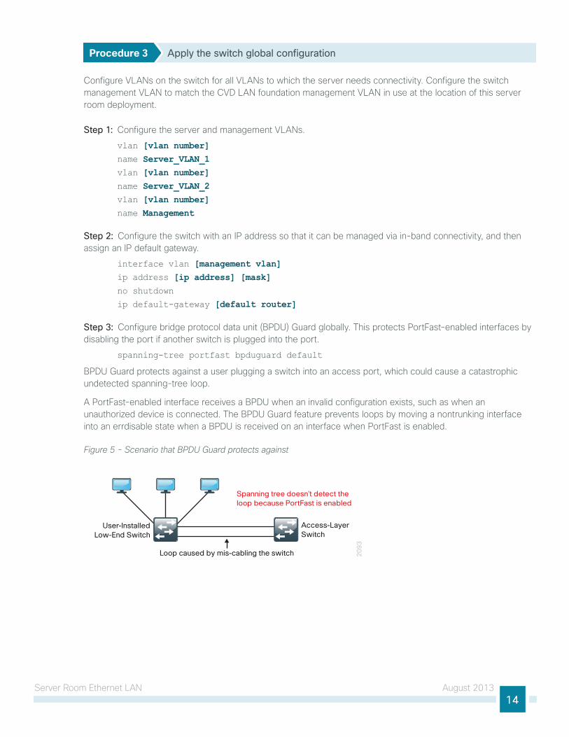
Step 3: configure bridge protocol data unit (BPdu) guard globally. this protects PortFast-enabled interfaces by disabling the port if another switch is plugged into the port.
spanning-tree portfast bpduguard default
BPdu guard protects against a user plugging a switch into an access port, which could cause a catastrophic undetected spanning-tree loop.
A PortFast-enabled interface receives a BPdu when an invalid configuration exists, such as when an unauthorized device is connected. the BPdu guard feature prevents loops by moving a nontrunking interface into an errdisable state when a BPdu is received on an interface when PortFast is enabled.
Figure 5 - Scenario that BPDU Guard protects against
20
93
Loop caused by mis-cabling the switch
User-InstalledLow-End Switch
Access-LayerSwitch
Spanning tree doesn’t detect theloop because PortFast is enabled
Server Room ethernet lAn August 201315
Examplevlan 148name Server_VLAN_1vlan 149name Server_VLAN_2vlan 106name Management!
interface vlan 106 ip address 10.5.7.4 255.255.255.128 no shutdown
ip default-gateway 10.5.7.1
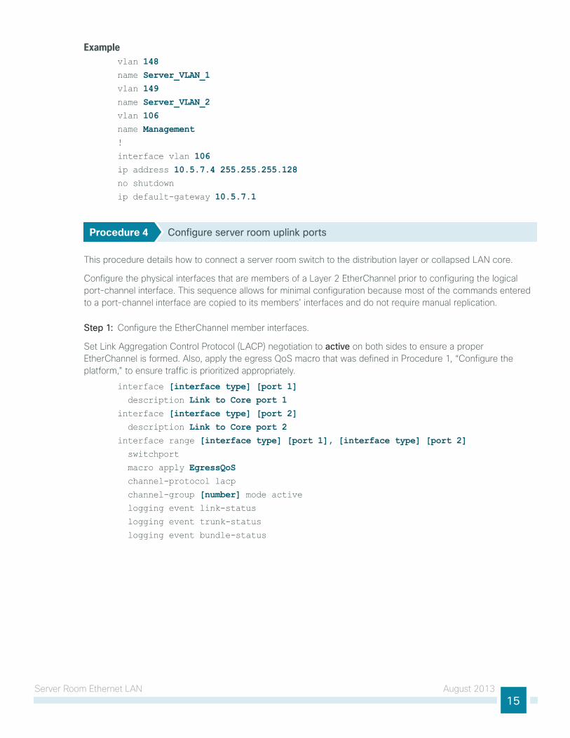
Procedure 4 Configure server room uplink ports
this procedure details how to connect a server room switch to the distribution layer or collapsed lAn core.
configure the physical interfaces that are members of a layer 2 etherchannel prior to configuring the logical port-channel interface. this sequence allows for minimal configuration because most of the commands entered to a port-channel interface are copied to its members’ interfaces and do not require manual replication.
Step 1: configure the etherchannel member interfaces.
Set link Aggregation control Protocol (lAcP) negotiation to active on both sides to ensure a proper etherchannel is formed. Also, apply the egress QoS macro that was defined in Procedure 1, “configure the platform,” to ensure traffic is prioritized appropriately.
interface [interface type] [port 1] description Link to Core port 1interface [interface type] [port 2] description Link to Core port 2interface range [interface type] [port 1], [interface type] [port 2] switchport
macro apply EgressQoS channel-protocol lacp
channel-group [number] mode active logging event link-status
logging event trunk-status
logging event bundle-status

Server Room ethernet lAn August 201316
Step 2: configure the 802.1Q trunk.
An 802.1Q trunk is used for the connection to this upstream device, which allows the uplink to provide layer 3 services to all the VlAns defined on the server room switch. Prune the VlAns allowed on the trunk to only the VlAns that are active on the server room switch. When using etherchannel, the interface type is port-channel, and the number must match the channel-group configured in Step 1.
interface Port-channel [number] description EtherChannel Link to Core switchport trunk encapsulation dot1q
switchport trunk allowed vlan [server vlan 1],[server vlan 2],[management vlan] switchport mode trunk
logging event link-status
no shutdown
next, mitigate the remote risk of a VlAn hopping attack on the trunk.
there is a remote possibility that an attacker can create a double 802.1Q encapsulated packet. if the attacker has specific knowledge of the 802.1Q native VlAn, a packet could be crafted that when processed, the first or outermost tag is removed when the packet is switched onto the untagged native VlAn. When the packet reaches the target switch, the inner or second tag is then processed and the potentially malicious packet is switched to the target VlAn.
Figure 6 - VLAN hopping attack
20
97
Attacker Host802.1Q Trunk
80
2.1
Q T
ags
802.1Q Trunk withNative VLAN A
AccessInterfaceVLAN B
Data
VLAN A
VLAN B VLAN B
Data Data
80
2.1
Q T
ag
At first glance, this appears to be a serious risk. however, the traffic in this attack scenario is in a single direction, and no return traffic can be switched by this mechanism. Additionally, this attack cannot work unless the attacker knows the native VlAn id.
Step 3: configure an unused VlAn on the switch-to-switch 802.1Q trunk link from the server room to the distribution layer. using a hard-to-guess, unused VlAn for the native VlAn reduces the possibility that a double 802.1Q-tagged packet can hop VlAns. if you are running the recommended etherchannel uplink to the lAn access layer switch, configure the switchport trunk native vlan on the port-channel interface.
vlan 999!
interface Port-channel [number] switchport trunk native vlan 999
Server Room ethernet lAn August 201317
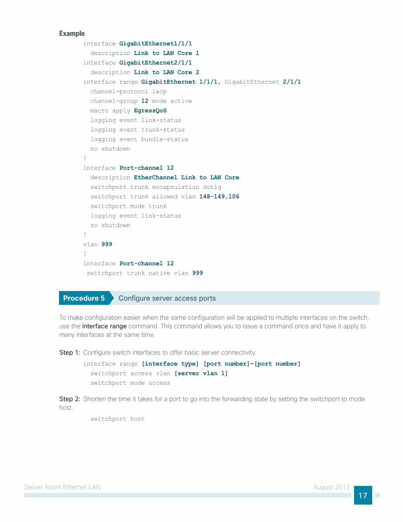
Exampleinterface GigabitEthernet1/1/1 description Link to LAN Core 1interface GigabitEthernet2/1/1 description Link to LAN Core 2interface range GigabitEthernet 1/1/1, GigabitEthernet 2/1/1 channel-protocol lacp
channel-group 12 mode active macro apply EgressQoS logging event link-status logging event trunk-status
logging event bundle-status
no shutdown
!
interface Port-channel 12 description EtherChannel Link to LAN Core switchport trunk encapsulation dot1q
switchport trunk allowed vlan 148-149,106 switchport mode trunk
logging event link-status
no shutdown
!
vlan 999!
interface Port-channel 12 switchport trunk native vlan 999
Procedure 5 Configure server access ports
to make configuration easier when the same configuration will be applied to multiple interfaces on the switch, use the interface range command. this command allows you to issue a command once and have it apply to many interfaces at the same time.
Step 1: configure switch interfaces to offer basic server connectivity.
interface range [interface type] [port number]–[port number] switchport access vlan [server vlan 1] switchport mode access
Step 2: Shorten the time it takes for a port to go into the forwarding state by setting the switchport to mode host.
switchport host
Server Room ethernet lAn August 201318
Step 3: if you want to trust the QoS markings on the traffic from the servers based on the QoS macro configuration, enter the following command.
macro apply EgressQoS
it is possible that your server or application may require special configuration like trunking or port channeling. Refer to vendor documentation for this information.
Reader Tip
Step 4: Save the running configuration that you have entered. it will be used as the startup configuration file when your switch is rebooted or power-cycled.
copy running-config startup-config
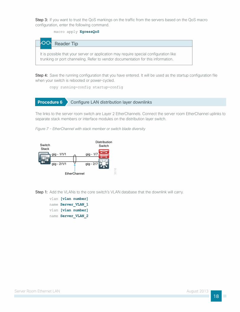
Procedure 6 Configure LAN distribution layer downlinks
the links to the server room switch are layer 2 etherchannels. connect the server room etherchannel uplinks to separate stack members or interface modules on the distribution layer switch.
Figure 7 - EtherChannel with stack member or switch blade diversity
30
16
SwitchStack
gig - 1/1/1
gig - 2/1/1
gig - 1/7
gig - 2/7
EtherChannel
DistributionSwitch
Step 1: Add the VlAns to the core switch’s VlAn database that the downlink will carry.
vlan [vlan number]name Server_VLAN_1vlan [vlan number]name Server_VLAN_2
Server Room ethernet lAn August 201319
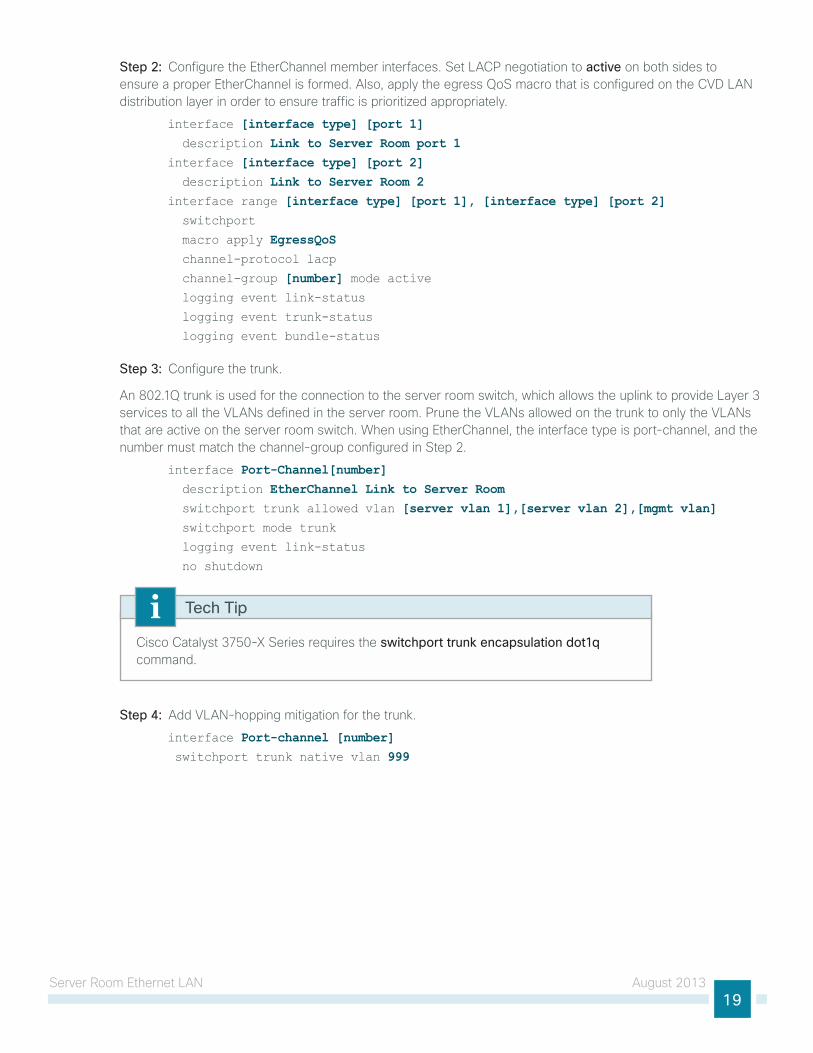
Step 2: configure the etherchannel member interfaces. Set lAcP negotiation to active on both sides to ensure a proper etherchannel is formed. Also, apply the egress QoS macro that is configured on the cVd lAn distribution layer in order to ensure traffic is prioritized appropriately.
interface [interface type] [port 1] description Link to Server Room port 1interface [interface type] [port 2] description Link to Server Room 2interface range [interface type] [port 1], [interface type] [port 2] switchport
macro apply EgressQoS channel-protocol lacp
channel-group [number] mode active logging event link-status
logging event trunk-status
logging event bundle-status
Step 3: configure the trunk.
An 802.1Q trunk is used for the connection to the server room switch, which allows the uplink to provide layer 3 services to all the VlAns defined in the server room. Prune the VlAns allowed on the trunk to only the VlAns that are active on the server room switch. When using etherchannel, the interface type is port-channel, and the number must match the channel-group configured in Step 2.
interface Port-Channel[number] description EtherChannel Link to Server Room switchport trunk allowed vlan [server vlan 1],[server vlan 2],[mgmt vlan] switchport mode trunk
logging event link-status
no shutdown
cisco catalyst 3750-X Series requires the switchport trunk encapsulation dot1q command.
Tech Tip
Step 4: Add VlAn-hopping mitigation for the trunk.
interface Port-channel [number] switchport trunk native vlan 999
Server Room ethernet lAn August 201320
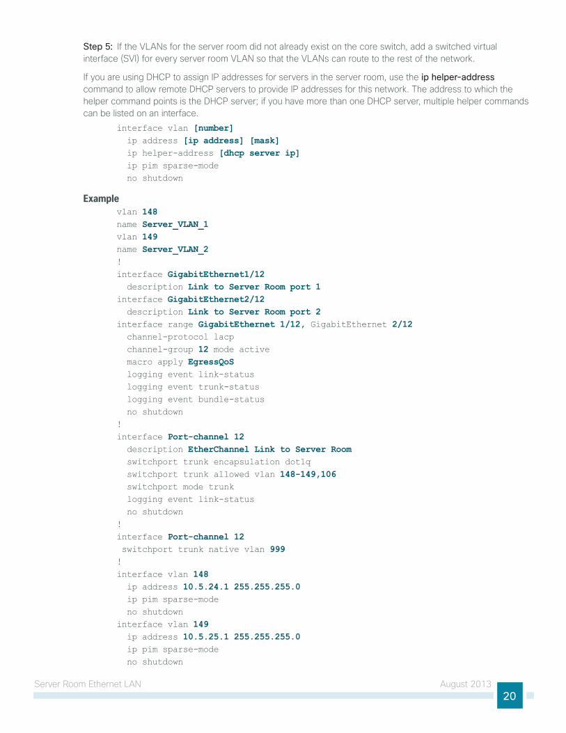
Step 5: if the VlAns for the server room did not already exist on the core switch, add a switched virtual interface (SVi) for every server room VlAn so that the VlAns can route to the rest of the network.
if you are using dhcP to assign iP addresses for servers in the server room, use the ip helper-address command to allow remote dhcP servers to provide iP addresses for this network. the address to which the helper command points is the dhcP server; if you have more than one dhcP server, multiple helper commands can be listed on an interface.
interface vlan [number] ip address [ip address] [mask] ip helper-address [dhcp server ip] ip pim sparse-mode no shutdown
Examplevlan 148name Server_VLAN_1vlan 149name Server_VLAN_2!interface GigabitEthernet1/12 description Link to Server Room port 1interface GigabitEthernet2/12 description Link to Server Room port 2interface range GigabitEthernet 1/12, GigabitEthernet 2/12 channel-protocol lacp channel-group 12 mode active macro apply EgressQoS logging event link-status logging event trunk-status logging event bundle-status no shutdown!interface Port-channel 12 description EtherChannel Link to Server Room switchport trunk encapsulation dot1q switchport trunk allowed vlan 148-149,106 switchport mode trunk logging event link-status no shutdown!interface Port-channel 12 switchport trunk native vlan 999!interface vlan 148 ip address 10.5.24.1 255.255.255.0 ip pim sparse-mode no shutdown interface vlan 149 ip address 10.5.25.1 255.255.255.0 ip pim sparse-mode no shutdown
Server Room Security August 201321
Server Room Security
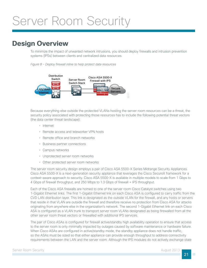
Design Overviewto minimize the impact of unwanted network intrusions, you should deploy firewalls and intrusion prevention systems (iPSs) between clients and centralized data resources.
Figure 8 - Deploy firewall inline to help protect data resources
30
17
LAN/WANInternet
Cisco ASA 5500-XFirewall with IPSServer Room
Switch Stack
DistributionSwitch
SecureServers
Because everything else outside the protected VlAns hosting the server room resources can be a threat, the security policy associated with protecting those resources has to include the following potential threat vectors (the data center threat landscape):
• internet
• Remote access and teleworker VPn hosts
• Remote office and branch networks
• Business partner connections
• campus networks
• unprotected server room networks
• other protected server room networks
the server room security design employs a pair of cisco ASA 5500-X Series Midrange Security Appliances. cisco ASA 5500-X is a next-generation security appliance that leverages the cisco SecureX framework for a context-aware approach to security. cisco ASA 5500-X is available in multiple models to scale from 1 gbps to 4 gbps of firewall throughput, and 250 Mbps to 1.3 gbps of firewall + iPS throughput.
each of the cisco ASA firewalls are homed to one of the server room cisco catalyst switches using two 1-gigabit ethernet links. the first 1-gigabit ethernet link on each cisco ASA is configured to carry traffic from the cVd lAn distribution layer. this link is designated as the outside VlAn for the firewall, and any hosts or servers that reside in that VlAn are outside the firewall and therefore receive no protection from cisco ASA for attacks originating from anywhere else in the organization’s network. the second 1-gigabit ethernet link on each cisco ASA is configured as a VlAn trunk to transport server room VlAns designated as being firewalled from all the other server room threat vectors or firewalled with additional iPS services.
the pair of cisco ASAs is configured for firewall active/standby high availability operation to ensure that access to the server room is only minimally impacted by outages caused by software maintenance or hardware failure. When cisco ASAs are configured in active/standby mode, the standby appliance does not handle traffic, so the ASAs must be sized so that either appliance can provide enough throughput to address connectivity requirements between the lAn and the server room. Although the iPS modules do not actively exchange state
Server Room Security August 201322
traffic, they participate in the firewall appliances’ active/standby status by way of reporting their status to the firewall’s status monitor. A firewall failover will occur if either the appliance itself has an issue or the iPS module becomes unavailable.
cisco ASAs are configured in routing mode; as a result, the secure network must be in a separate subnet from the client subnets. iP subnet allocation would be simplified if the appliance were deployed in transparent mode; however, hosts might inadvertently be connected to the wrong VlAn, where they would still be able to communicate with the network, incurring an unwanted security exposure.
the server room iPS monitors for and mitigates potential malicious activity that is contained within traffic allowed by the security policy defined on cisco ASA. the iPS sensors can be deployed in promiscuous, or IDS, mode so that they only monitor and alert for abnormal traffic. the iPS sensors can be deployed in inline, or IPS, mode in order to fully engage their intrusion prevention capabilities, wherein they will block malicious traffic before it reaches its destination. the choice to have the sensor drop traffic or not is one that is influenced by several factors: risk tolerance for having a security incident, risk aversion for inadvertently dropping valid traffic, and other possibly externally driven reasons such as compliance requirements for iPS. the ability to run in idS or iPS mode is highly configurable to allow the maximum flexibility in meeting a specific security policy.
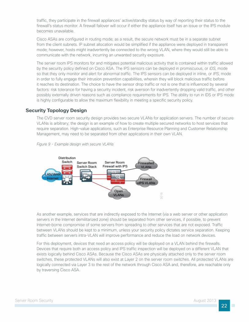
Security Topology Design the cVd server room security design provides two secure VlAns for application servers. the number of secure VlAns is arbitrary; the design is an example of how to create multiple secured networks to host services that require separation. high-value applications, such as enterprise Resource Planning and customer Relationship Management, may need to be separated from other applications in their own VlAn.
Figure 9 - Example design with secure VLANs
30
18
LAN/WANInternet
Server Room Firewall with IPS
Server RoomSwitch Stack
DistributionSwitch Firewalled
VLANs
Firewall+IPS VLANs
OpenVLANs
As another example, services that are indirectly exposed to the internet (via a web server or other application servers in the internet demilitarized zone) should be separated from other services, if possible, to prevent internet-borne compromise of some servers from spreading to other services that are not exposed. traffic between VlAns should be kept to a minimum, unless your security policy dictates service separation. Keeping traffic between servers intra-VlAn will improve performance and reduce the load on network devices.
For this deployment, devices that need an access policy will be deployed on a VlAn behind the firewalls. devices that require both an access policy and iPS traffic inspection will be deployed on a different VlAn that exists logically behind cisco ASAs. Because the cisco ASAs are physically attached only to the server room switches, these protected VlAns will also exist at layer 2 on the server room switches. All protected VlAns are logically connected via layer 3 to the rest of the network through cisco ASA and, therefore, are reachable only by traversing cisco ASA.
Server Room Security August 201323
Security Policy DevelopmentAn organization should have an it security policy as a starting point in defining its firewall policy. if there is no organization-wide security policy, it will be very difficult to define an effective policy for the organization while maintaining a secure computing environment.
A detailed examination of regulatory compliance considerations exceeds the scope of this document. you should include industry regulation in your network security design. noncompliance may result in regulatory penalties such as fines or suspension of business activity.
Reader Tip
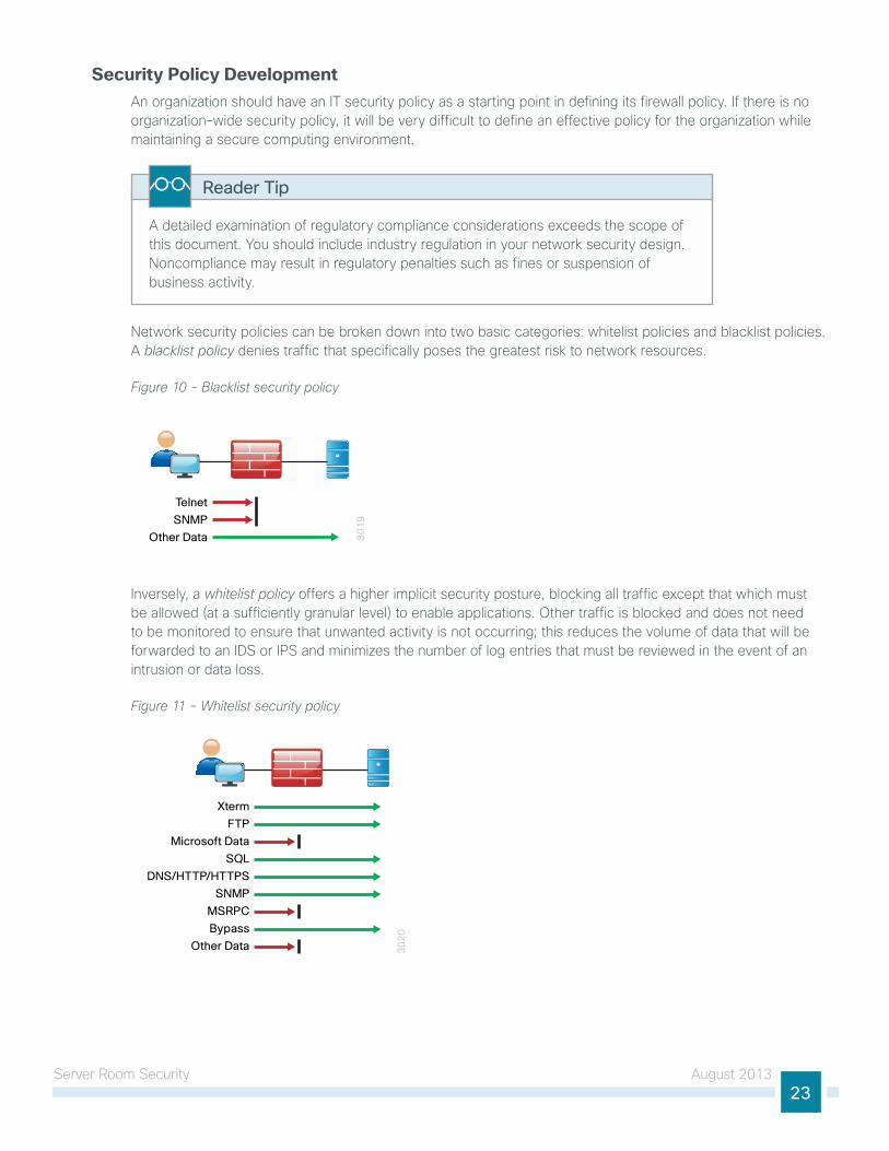
network security policies can be broken down into two basic categories: whitelist policies and blacklist policies. A blacklist policy denies traffic that specifically poses the greatest risk to network resources.
Figure 10 - Blacklist security policy
30
19
Telnet
SNMP
Other Data
inversely, a whitelist policy offers a higher implicit security posture, blocking all traffic except that which must be allowed (at a sufficiently granular level) to enable applications. other traffic is blocked and does not need to be monitored to ensure that unwanted activity is not occurring; this reduces the volume of data that will be forwarded to an idS or iPS and minimizes the number of log entries that must be reviewed in the event of an intrusion or data loss.
Figure 11 - Whitelist security policy
30
20
Xterm
FTP
Microsoft Data
SQL
DNS/HTTP/HTTPS
SNMP
MSRPC
Bypass
Other Data
Server Room Security August 201324
Whitelist policies can be identified by the last rule of the policy rule-set: whitelist policies always end with a rule to deny any traffic that has not been denied or allowed by previous rules. cisco ASA firewalls implicitly add a deny-all rule at the end of an access list. Blacklist policies include an explicit rule, prior to the implicit deny-all rule, to allow any traffic that is not explicitly allowed or denied.
A blacklist policy is simpler to maintain and less likely to interfere with network applications. A whitelist policy is the best-practice option if you have the opportunity to examine the network’s requirements and adjust the policy to avoid interfering with desired network activity. Whitelist policies are generally better positioned to meet regulatory requirements because only traffic that must be allowed in order to conduct business is allowed.
Whether you choose a whitelist or blacklist policy basis, idS or iPS can monitor malicious activity on otherwise trustworthy application traffic. At a minimum, idS or iPS can aid with forensics to determine the origin of a data breach. iPS can detect and prevent known attacks as they occur and provide detailed information to track the malicious activity to its source. idS or iPS may also be required by the regulatory oversight to which a network is subject (for example, Pci 2.0).
A blacklist policy that blocks high-risk traffic offers a lower-impact, less-secure option (as compared to a whitelist policy) in cases where either:
• A detailed study of the network’s application activity is impractical.
• the network availability requirements prohibit application troubleshooting.
if identifying all of the application requirements is not practical, an organization can apply a blacklist policy with logging enabled to develop a detailed study of the policy. With details about its network’s behavior in hand, an organization can more easily develop an effective whitelist policy.
Deployment DetailsFor deployment in the server room, cisco ASA 5500-X firewall with iPS will be deployed to enforce the security policy between the network core and the application server network, and between the different application server networks.
cisco ASA is set up as a highly available active/standby pair. Active/standby:
• is much simpler than an active/active configuration.
• Allows the use of the same appliance for firewall and VPn (VPn functionality is disabled when cisco ASA is configured as active/active).
the performance needs in this design do not surpass the performance of a single appliance.
in the event that the active appliance fails or needs to be taken out of service for maintenance, the secondary appliance will take over all firewall and iPS functions.
cisco ASA is statically routed to the cVd lAn distribution on the outside interface in order to simplify the routing configuration. A second interface is trunked to the server room switch with a VlAn interface for each application server network.
Server Room Security August 201325
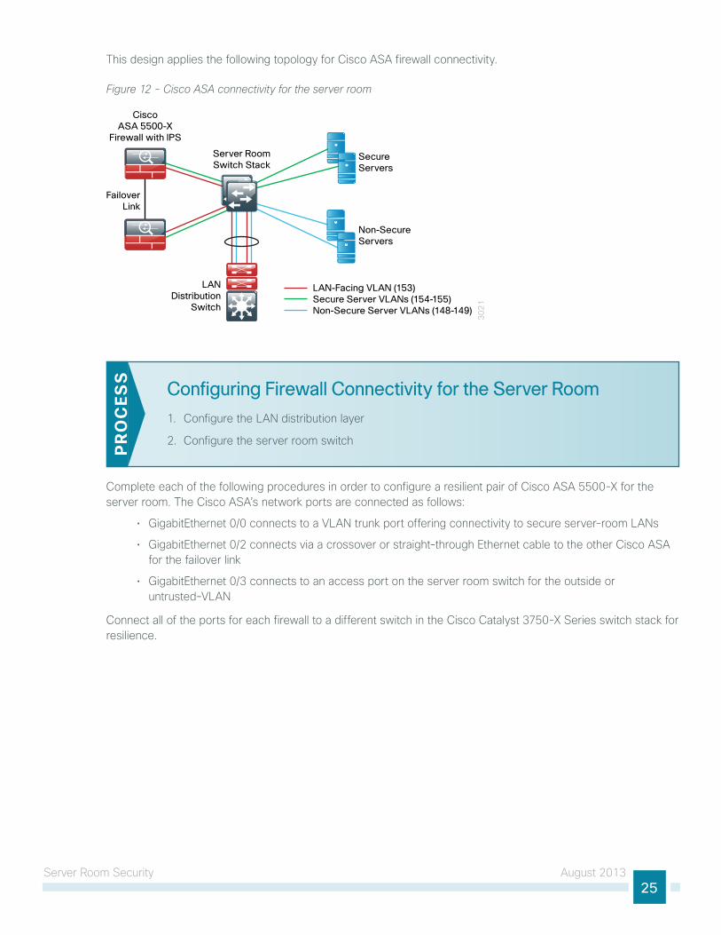
this design applies the following topology for cisco ASA firewall connectivity.
Figure 12 - Cisco ASA connectivity for the server room
30
21
Server RoomSwitch Stack
FailoverLink
Secure Servers
Non-Secure Servers
LAN-Facing VLAN (153)Secure Server VLANs (154-155)Non-Secure Server VLANs (148-149)
CiscoASA 5500-X
Firewall with IPS
LANDistribution
Switch
Configuring Firewall Connectivity for the Server Room
1. configure the lAn distribution layer
2. configure the server room switchPR
OC
ESS
complete each of the following procedures in order to configure a resilient pair of cisco ASA 5500-X for the server room. the cisco ASA’s network ports are connected as follows:
• gigabitethernet 0/0 connects to a VlAn trunk port offering connectivity to secure server-room lAns
• gigabitethernet 0/2 connects via a crossover or straight-through ethernet cable to the other cisco ASA for the failover link
• gigabitethernet 0/3 connects to an access port on the server room switch for the outside or untrusted-VlAn
connect all of the ports for each firewall to a different switch in the cisco catalyst 3750-X Series switch stack for resilience.
Server Room Security August 201326
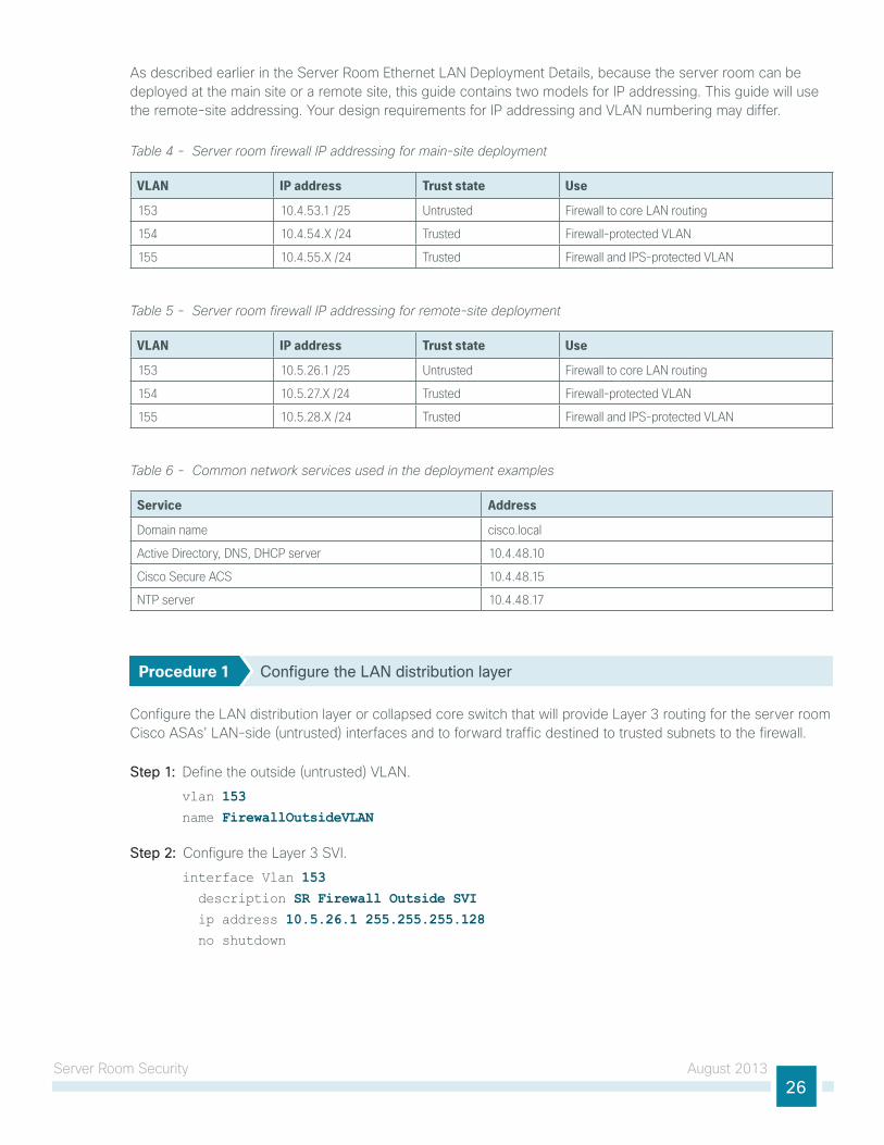
As described earlier in the Server Room ethernet lAn deployment details, because the server room can be deployed at the main site or a remote site, this guide contains two models for iP addressing. this guide will use the remote-site addressing. your design requirements for iP addressing and VlAn numbering may differ.
Table 4 - Server room firewall IP addressing for main-site deployment
VLAN IP address Trust state Use
153 10.4.53.1 /25 Untrusted Firewall to core LAN routing
154 10.4.54.X /24 Trusted Firewall-protected VLAN
155 10.4.55.X /24 Trusted Firewall and IPS-protected VLAN
Table 5 - Server room firewall IP addressing for remote-site deployment
VLAN IP address Trust state Use
153 10.5.26.1 /25 Untrusted Firewall to core LAN routing
154 10.5.27.X /24 Trusted Firewall-protected VLAN
155 10.5.28.X /24 Trusted Firewall and IPS-protected VLAN
Table 6 - Common network services used in the deployment examples
Service Address
Domain name cisco.local
Active Directory, DNS, DHCP server 10.4.48.10
Cisco Secure ACS 10.4.48.15
NTP server 10.4.48.17
Procedure 1 Configure the LAN distribution layer
configure the lAn distribution layer or collapsed core switch that will provide layer 3 routing for the server room cisco ASAs’ lAn-side (untrusted) interfaces and to forward traffic destined to trusted subnets to the firewall.
Step 1: define the outside (untrusted) VlAn.
vlan 153 name FirewallOutsideVLAN
Step 2: configure the layer 3 SVi.
interface Vlan 153 description SR Firewall Outside SVI ip address 10.5.26.1 255.255.255.128 no shutdown
Server Room Security August 201327
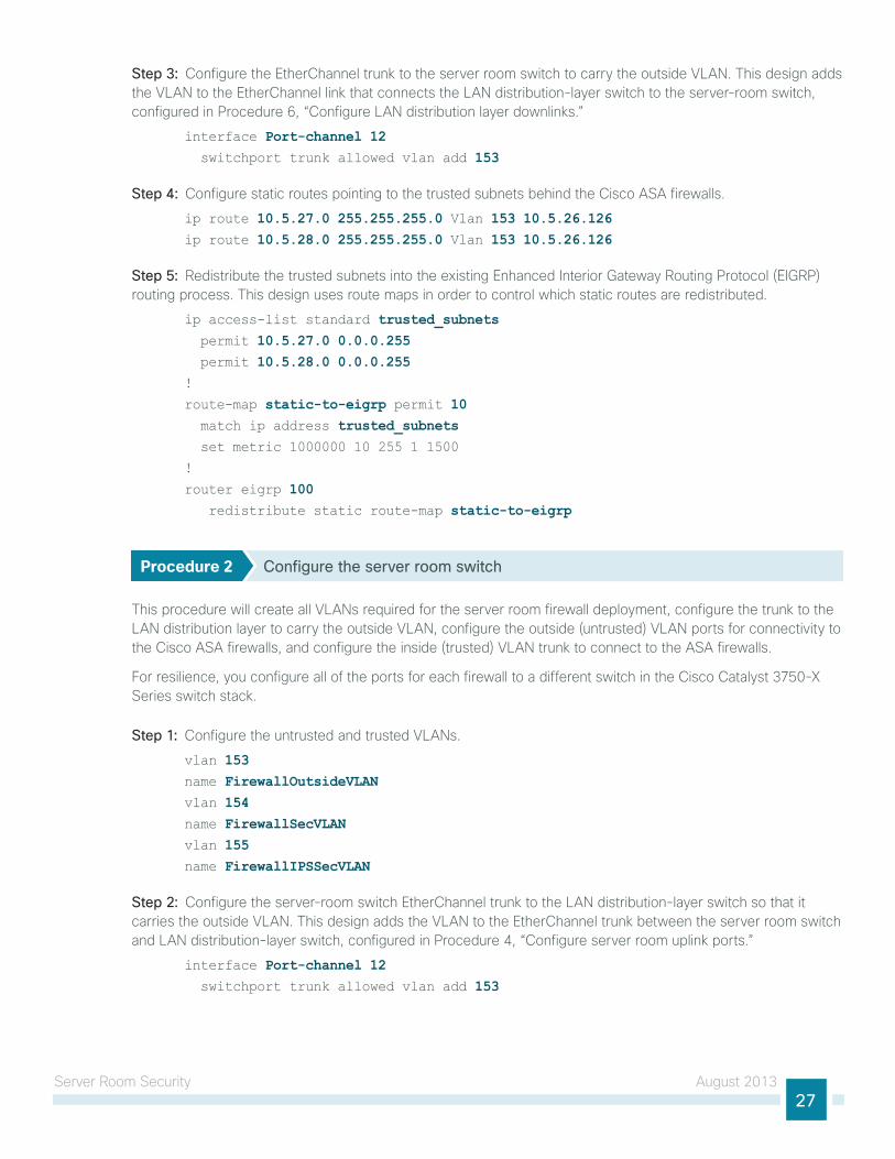
Step 3: configure the etherchannel trunk to the server room switch to carry the outside VlAn. this design adds the VlAn to the etherchannel link that connects the lAn distribution-layer switch to the server-room switch, configured in Procedure 6, “configure lAn distribution layer downlinks.”
interface Port-channel 12 switchport trunk allowed vlan add 153
Step 4: configure static routes pointing to the trusted subnets behind the cisco ASA firewalls.
ip route 10.5.27.0 255.255.255.0 Vlan 153 10.5.26.126ip route 10.5.28.0 255.255.255.0 Vlan 153 10.5.26.126
Step 5: Redistribute the trusted subnets into the existing enhanced interior gateway Routing Protocol (eigRP) routing process. this design uses route maps in order to control which static routes are redistributed.
ip access-list standard trusted_subnets permit 10.5.27.0 0.0.0.255 permit 10.5.28.0 0.0.0.255!
route-map static-to-eigrp permit 10 match ip address trusted_subnets set metric 1000000 10 255 1 1500
!
router eigrp 100 redistribute static route-map static-to-eigrp
Procedure 2 Configure the server room switch
this procedure will create all VlAns required for the server room firewall deployment, configure the trunk to the lAn distribution layer to carry the outside VlAn, configure the outside (untrusted) VlAn ports for connectivity to the cisco ASA firewalls, and configure the inside (trusted) VlAn trunk to connect to the ASA firewalls.
For resilience, you configure all of the ports for each firewall to a different switch in the cisco catalyst 3750-X Series switch stack.
Step 1: configure the untrusted and trusted VlAns.
vlan 153 name FirewallOutsideVLANvlan 154name FirewallSecVLANvlan 155name FirewallIPSSecVLAN
Step 2: configure the server-room switch etherchannel trunk to the lAn distribution-layer switch so that it carries the outside VlAn. this design adds the VlAn to the etherchannel trunk between the server room switch and lAn distribution-layer switch, configured in Procedure 4, “configure server room uplink ports.”
interface Port-channel 12 switchport trunk allowed vlan add 153
Server Room Security August 201328
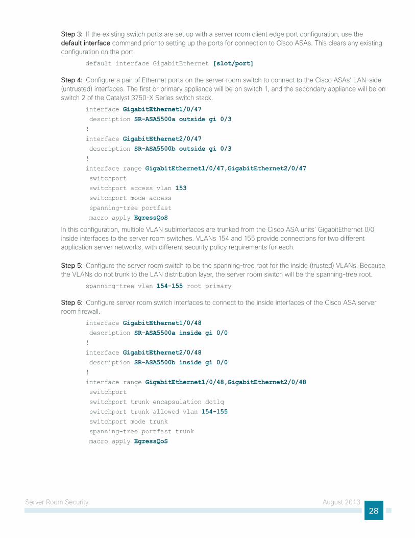
Step 3: if the existing switch ports are set up with a server room client edge port configuration, use the default interface command prior to setting up the ports for connection to cisco ASAs. this clears any existing configuration on the port.
default interface GigabitEthernet [slot/port]
Step 4: configure a pair of ethernet ports on the server room switch to connect to the cisco ASAs’ lAn-side (untrusted) interfaces. the first or primary appliance will be on switch 1, and the secondary appliance will be on switch 2 of the catalyst 3750-X Series switch stack.
interface GigabitEthernet1/0/47 description SR-ASA5500a outside gi 0/3!
interface GigabitEthernet2/0/47 description SR-ASA5500b outside gi 0/3!
interface range GigabitEthernet1/0/47,GigabitEthernet2/0/47 switchport
switchport access vlan 153 switchport mode access
spanning-tree portfast
macro apply EgressQoS
in this configuration, multiple VlAn subinterfaces are trunked from the cisco ASA units’ gigabitethernet 0/0 inside interfaces to the server room switches. VlAns 154 and 155 provide connections for two different application server networks, with different security policy requirements for each.
Step 5: configure the server room switch to be the spanning-tree root for the inside (trusted) VlAns. Because the VlAns do not trunk to the lAn distribution layer, the server room switch will be the spanning-tree root.
spanning-tree vlan 154-155 root primary
Step 6: configure server room switch interfaces to connect to the inside interfaces of the cisco ASA server room firewall.
interface GigabitEthernet1/0/48 description SR-ASA5500a inside gi 0/0!
interface GigabitEthernet2/0/48 description SR-ASA5500b inside gi 0/0!
interface range GigabitEthernet1/0/48,GigabitEthernet2/0/48 switchport
switchport trunk encapsulation dot1q
switchport trunk allowed vlan 154-155 switchport mode trunk
spanning-tree portfast trunk
macro apply EgressQoS
Server Room Security August 201329
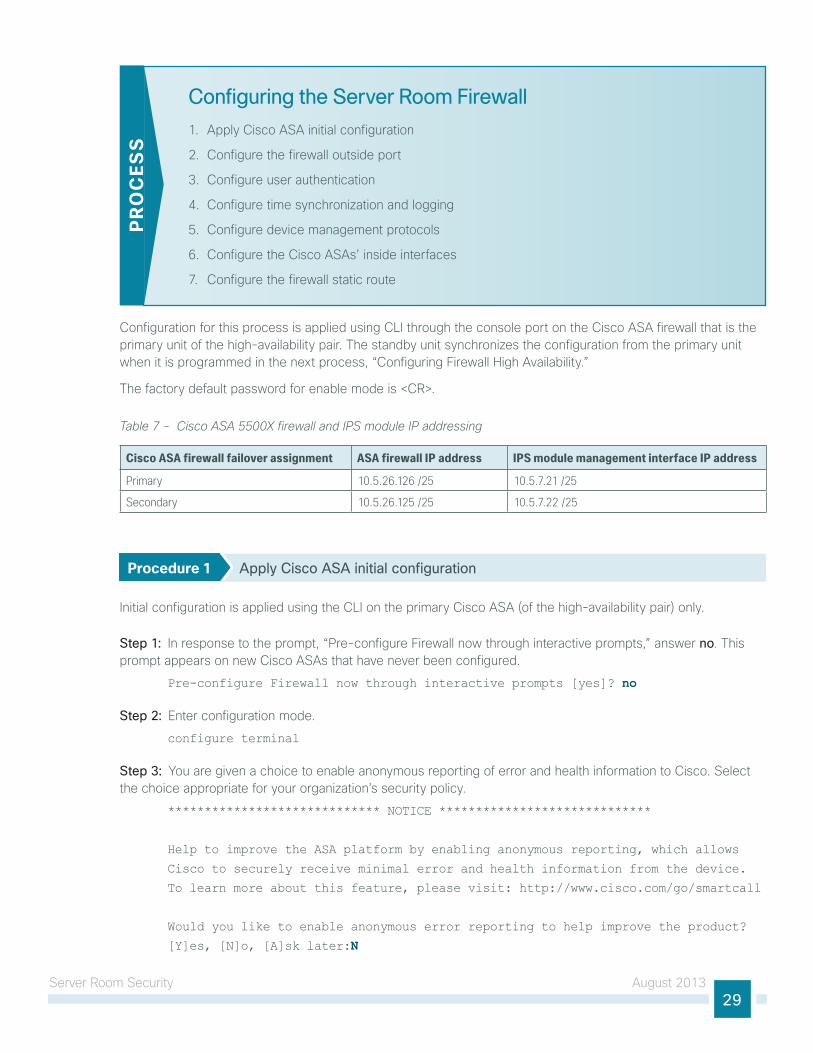
Configuring the Server Room Firewall
1. Apply cisco ASA initial configuration
2. configure the firewall outside port
3. configure user authentication
4. configure time synchronization and logging
5. configure device management protocols
6. configure the cisco ASAs’ inside interfaces
7. configure the firewall static route
PR
OC
ESS
configuration for this process is applied using cli through the console port on the cisco ASA firewall that is the primary unit of the high-availability pair. the standby unit synchronizes the configuration from the primary unit when it is programmed in the next process, “configuring Firewall high Availability.”
the factory default password for enable mode is <cR>.
Table 7 - Cisco ASA 5500X firewall and IPS module IP addressing
Cisco ASA firewall failover assignment ASA firewall IP address IPS module management interface IP address
Primary 10.5.26.126 /25 10.5.7.21 /25
Secondary 10.5.26.125 /25 10.5.7.22 /25
Procedure 1 Apply Cisco ASA initial configuration
initial configuration is applied using the cli on the primary cisco ASA (of the high-availability pair) only.
Step 1: in response to the prompt, “Pre-configure Firewall now through interactive prompts,” answer no. this prompt appears on new cisco ASAs that have never been configured.
Pre-configure Firewall now through interactive prompts [yes]? no
Step 2: enter configuration mode.
configure terminal
Step 3: you are given a choice to enable anonymous reporting of error and health information to cisco. Select the choice appropriate for your organization’s security policy.
***************************** NOTICE *****************************
Help to improve the ASA platform by enabling anonymous reporting, which allows
Cisco to securely receive minimal error and health information from the device.
To learn more about this feature, please visit: http://www.cisco.com/go/smartcall
Would you like to enable anonymous error reporting to help improve the product?
[Y]es, [N]o, [A]sk later:N
Server Room Security August 201330
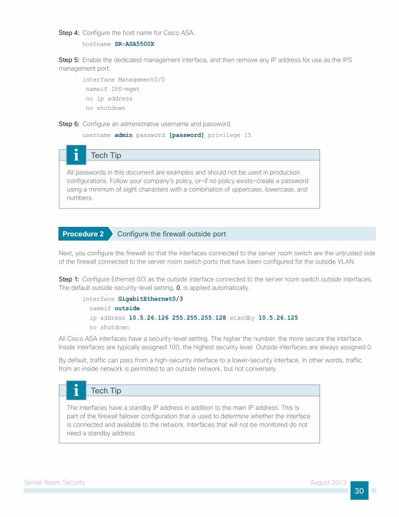
Step 4: configure the host name for cisco ASA.
hostname SR-ASA5500X
Step 5: enable the dedicated management interface, and then remove any iP address for use as the iPS management port.
interface Management0/0
nameif IPS-mgmt
no ip address
no shutdown
Step 6: configure an administrative username and password.
username admin password [password] privilege 15
All passwords in this document are examples and should not be used in production configurations. Follow your company’s policy, or—if no policy exists—create a password using a minimum of eight characters with a combination of uppercase, lowercase, and numbers.
Tech Tip
Procedure 2 Configure the firewall outside port
next, you configure the firewall so that the interfaces connected to the server room switch are the untrusted side of the firewall connected to the server room switch ports that have been configured for the outside VlAn.
Step 1: configure ethernet 0/3 as the outside interface connected to the server room switch outside interfaces. the default outside security-level setting, 0, is applied automatically.
interface GigabitEthernet0/3 nameif outside ip address 10.5.26.126 255.255.255.128 standby 10.5.26.125 no shutdown
All cisco ASA interfaces have a security-level setting. the higher the number, the more secure the interface. inside interfaces are typically assigned 100, the highest security level. outside interfaces are always assigned 0.
By default, traffic can pass from a high-security interface to a lower-security interface. in other words, traffic from an inside network is permitted to an outside network, but not conversely.
the interfaces have a standby iP address in addition to the main iP address. this is part of the firewall failover configuration that is used to determine whether the interface is connected and available to the network. interfaces that will not be monitored do not need a standby address.
Tech Tip
Server Room Security August 201331
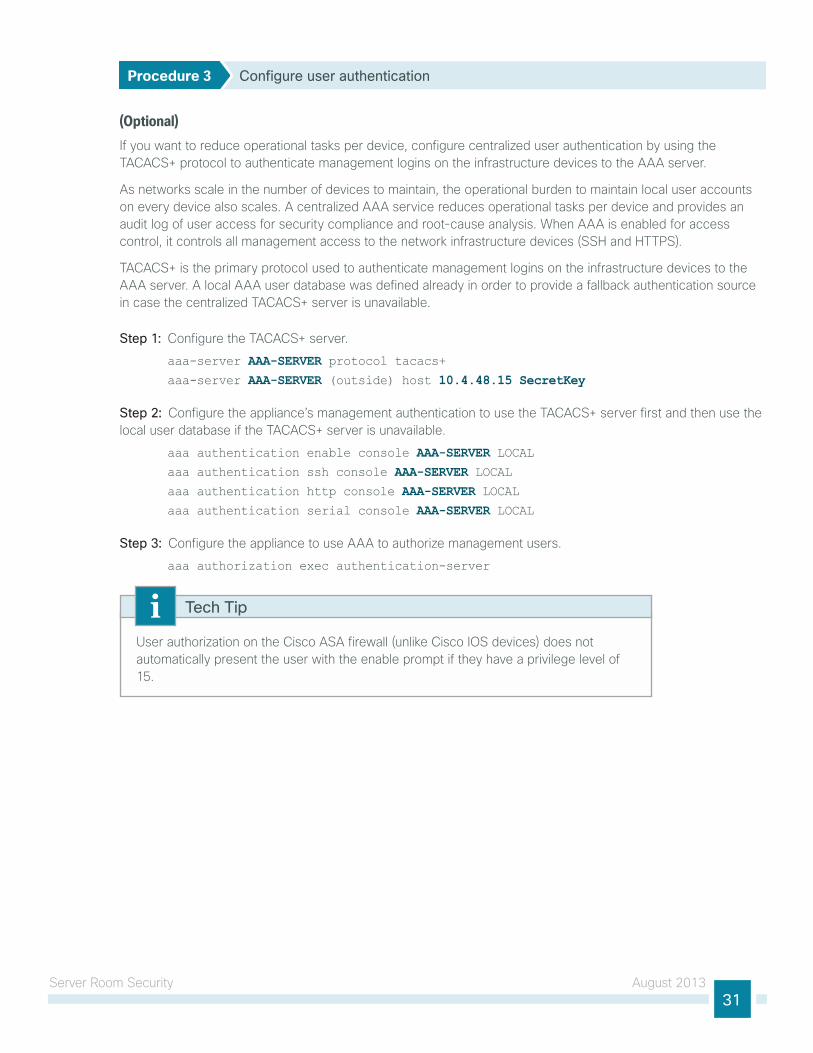
Procedure 3 Configure user authentication
(Optional)if you want to reduce operational tasks per device, configure centralized user authentication by using the tAcAcS+ protocol to authenticate management logins on the infrastructure devices to the AAA server.
As networks scale in the number of devices to maintain, the operational burden to maintain local user accounts on every device also scales. A centralized AAA service reduces operational tasks per device and provides an audit log of user access for security compliance and root-cause analysis. When AAA is enabled for access control, it controls all management access to the network infrastructure devices (SSh and httPS).
tAcAcS+ is the primary protocol used to authenticate management logins on the infrastructure devices to the AAA server. A local AAA user database was defined already in order to provide a fallback authentication source in case the centralized tAcAcS+ server is unavailable.
Step 1: configure the tAcAcS+ server.
aaa-server AAA-SERVER protocol tacacs+aaa-server AAA-SERVER (outside) host 10.4.48.15 SecretKey
Step 2: configure the appliance’s management authentication to use the tAcAcS+ server first and then use the local user database if the tAcAcS+ server is unavailable.
aaa authentication enable console AAA-SERVER LOCALaaa authentication ssh console AAA-SERVER LOCALaaa authentication http console AAA-SERVER LOCALaaa authentication serial console AAA-SERVER LOCAL
Step 3: configure the appliance to use AAA to authorize management users.
aaa authorization exec authentication-server
user authorization on the cisco ASA firewall (unlike cisco ioS devices) does not automatically present the user with the enable prompt if they have a privilege level of 15.
Tech Tip
Server Room Security August 201332
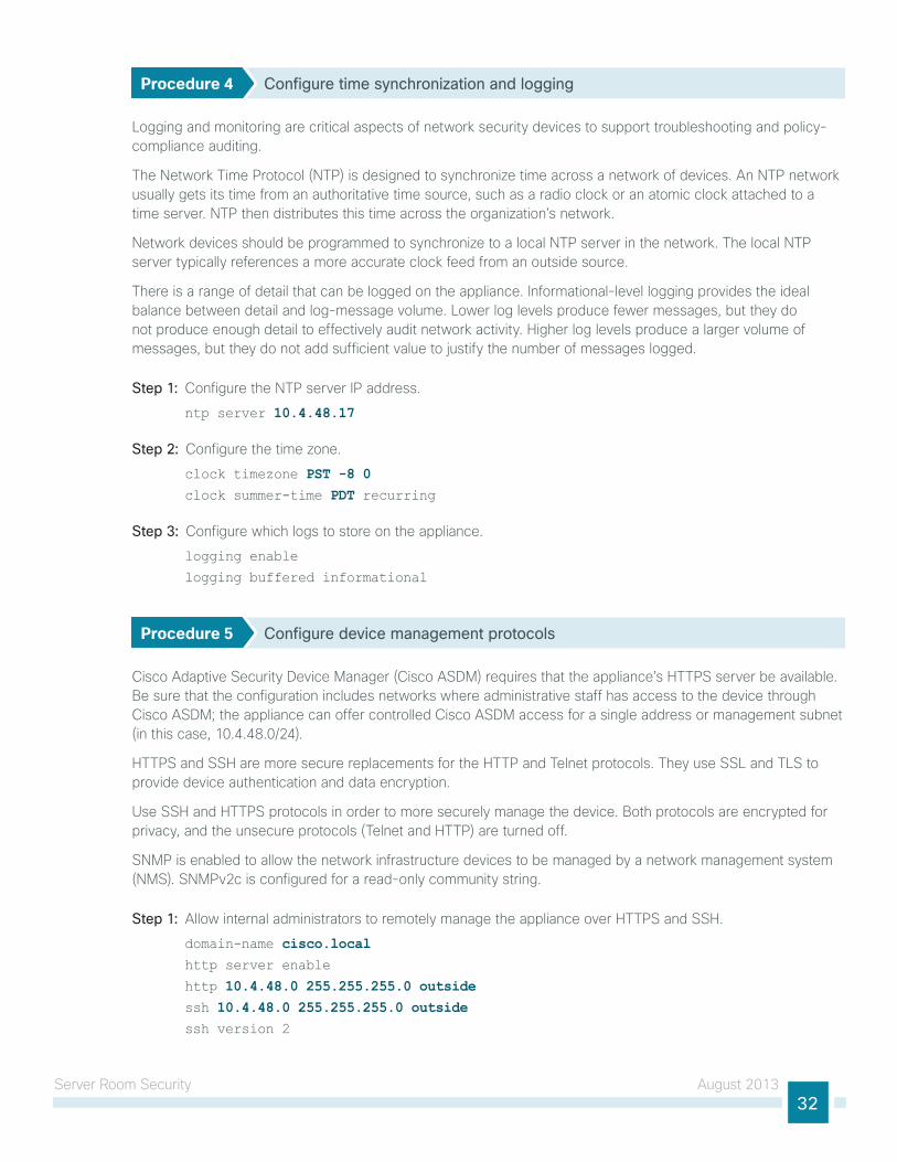
Procedure 4 Configure time synchronization and logging
logging and monitoring are critical aspects of network security devices to support troubleshooting and policy-compliance auditing.
the network time Protocol (ntP) is designed to synchronize time across a network of devices. An ntP network usually gets its time from an authoritative time source, such as a radio clock or an atomic clock attached to a time server. ntP then distributes this time across the organization’s network.
network devices should be programmed to synchronize to a local ntP server in the network. the local ntP server typically references a more accurate clock feed from an outside source.
there is a range of detail that can be logged on the appliance. informational-level logging provides the ideal balance between detail and log-message volume. lower log levels produce fewer messages, but they do not produce enough detail to effectively audit network activity. higher log levels produce a larger volume of messages, but they do not add sufficient value to justify the number of messages logged.
Step 1: configure the ntP server iP address.
ntp server 10.4.48.17
Step 2: configure the time zone.
clock timezone PST -8 0clock summer-time PDT recurring
Step 3: configure which logs to store on the appliance.
logging enable
logging buffered informational
Procedure 5 Configure device management protocols
cisco Adaptive Security device Manager (cisco ASdM) requires that the appliance’s httPS server be available. Be sure that the configuration includes networks where administrative staff has access to the device through cisco ASdM; the appliance can offer controlled cisco ASdM access for a single address or management subnet (in this case, 10.4.48.0/24).
httPS and SSh are more secure replacements for the httP and telnet protocols. they use SSl and tlS to provide device authentication and data encryption.
use SSh and httPS protocols in order to more securely manage the device. Both protocols are encrypted for privacy, and the unsecure protocols (telnet and httP) are turned off.
SnMP is enabled to allow the network infrastructure devices to be managed by a network management system (nMS). SnMPv2c is configured for a read-only community string.
Step 1: Allow internal administrators to remotely manage the appliance over httPS and SSh.
domain-name cisco.local http server enable
http 10.4.48.0 255.255.255.0 outside ssh 10.4.48.0 255.255.255.0 outsidessh version 2
Server Room Security August 201333
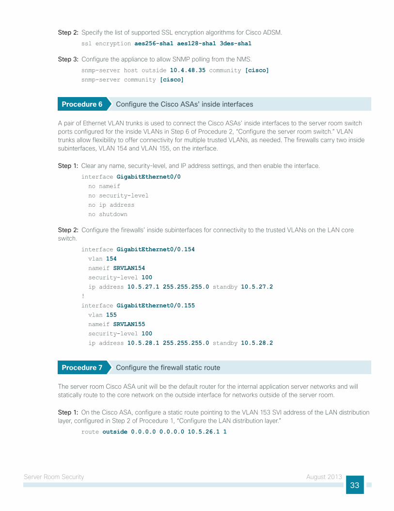
Step 2: Specify the list of supported SSl encryption algorithms for cisco AdSM.
ssl encryption aes256-sha1 aes128-sha1 3des-sha1
Step 3: configure the appliance to allow SnMP polling from the nMS.
snmp-server host outside 10.4.48.35 community [cisco]snmp-server community [cisco]
Procedure 6 Configure the Cisco ASAs’ inside interfaces
A pair of ethernet VlAn trunks is used to connect the cisco ASAs’ inside interfaces to the server room switch ports configured for the inside VlAns in Step 6 of Procedure 2, “configure the server room switch.” VlAn trunks allow flexibility to offer connectivity for multiple trusted VlAns, as needed. the firewalls carry two inside subinterfaces, VlAn 154 and VlAn 155, on the interface.
Step 1: clear any name, security-level, and iP address settings, and then enable the interface.
interface GigabitEthernet0/0 no nameif
no security-level
no ip address
no shutdown
Step 2: configure the firewalls’ inside subinterfaces for connectivity to the trusted VlAns on the lAn core switch.
interface GigabitEthernet0/0.154 vlan 154 nameif SRVLAN154 security-level 100 ip address 10.5.27.1 255.255.255.0 standby 10.5.27.2!
interface GigabitEthernet0/0.155 vlan 155 nameif SRVLAN155 security-level 100 ip address 10.5.28.1 255.255.255.0 standby 10.5.28.2
Procedure 7 Configure the firewall static route
the server room cisco ASA unit will be the default router for the internal application server networks and will statically route to the core network on the outside interface for networks outside of the server room.
Step 1: on the cisco ASA, configure a static route pointing to the VlAn 153 SVi address of the lAn distribution layer, configured in Step 2 of Procedure 1, “configure the lAn distribution layer.”
route outside 0.0.0.0 0.0.0.0 10.5.26.1 1
Server Room Security August 201334
Configuring Firewall High Availability
1. configure hA on the primary appliance
2. configure hA on the secondary appliancePR
OC
ESS
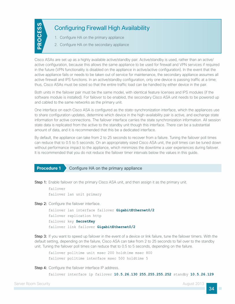
cisco ASAs are set up as a highly available active/standby pair. Active/standby is used, rather than an active/active configuration, because this allows the same appliance to be used for firewall and VPn services if required in the future (VPn functionality is disabled on the appliance in active/active configuration). in the event that the active appliance fails or needs to be taken out of service for maintenance, the secondary appliance assumes all active firewall and iPS functions. in an active/standby configuration, only one device is passing traffic at a time; thus, cisco ASAs must be sized so that the entire traffic load can be handled by either device in the pair.
Both units in the failover pair must be the same model, with identical feature licenses and iPS modules (if the software module is installed). For failover to be enabled, the secondary cisco ASA unit needs to be powered up and cabled to the same networks as the primary unit.
one interface on each cisco ASA is configured as the state-synchronization interface, which the appliances use to share configuration updates, determine which device in the high-availability pair is active, and exchange state information for active connections. the failover interface carries the state synchronization information. All session state data is replicated from the active to the standby unit though this interface. there can be a substantial amount of data, and it is recommended that this be a dedicated interface.
By default, the appliance can take from 2 to 25 seconds to recover from a failure. tuning the failover poll times can reduce that to 0.5 to 5 seconds. on an appropriately sized cisco ASA unit, the poll times can be tuned down without performance impact to the appliance, which minimizes the downtime a user experiences during failover. it is recommended that you do not reduce the failover timer intervals below the values in this guide.
Procedure 1 Configure HA on the primary appliance
Step 1: enable failover on the primary cisco ASA unit, and then assign it as the primary unit.
failover
failover lan unit primary
Step 2: configure the failover interface.
failover lan interface failover GigabitEthernet0/2 failover replication http
failover key SecretKey failover link failover GigabitEthernet0/2
Step 3: if you want to speed up failover in the event of a device or link failure, tune the failover timers. With the default setting, depending on the failure, cisco ASA can take from 2 to 25 seconds to fail over to the standby unit. tuning the failover poll times can reduce that to 0.5 to 5 seconds, depending on the failure.
failover polltime unit msec 200 holdtime msec 800
failover polltime interface msec 500 holdtime 5
Step 4: configure the failover interface iP address.
failover interface ip failover 10.5.26.130 255.255.255.252 standby 10.5.26.129
Server Room Security August 201335
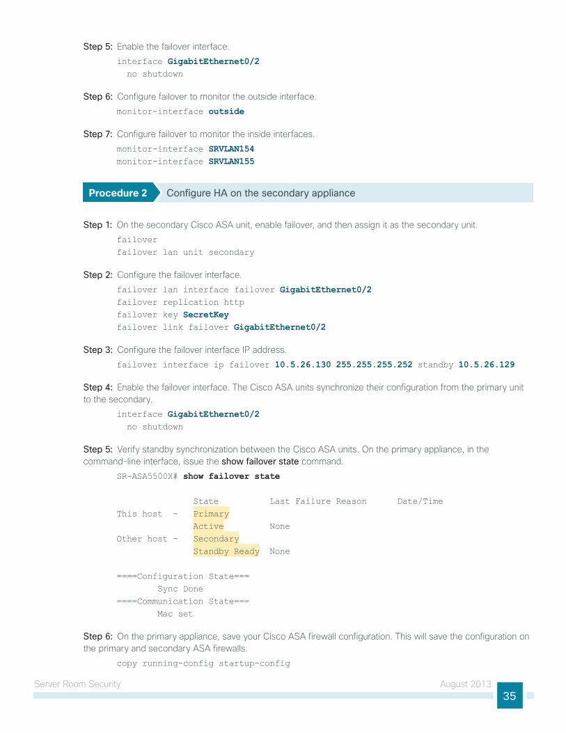
Step 5: enable the failover interface.interface GigabitEthernet0/2 no shutdown
Step 6: configure failover to monitor the outside interface.monitor-interface outside
Step 7: configure failover to monitor the inside interfaces.monitor-interface SRVLAN154monitor-interface SRVLAN155
Procedure 2 Configure HA on the secondary appliance
Step 1: on the secondary cisco ASA unit, enable failover, and then assign it as the secondary unit.failover failover lan unit secondary
Step 2: configure the failover interface.failover lan interface failover GigabitEthernet0/2 failover replication httpfailover key SecretKey failover link failover GigabitEthernet0/2
Step 3: configure the failover interface iP address.failover interface ip failover 10.5.26.130 255.255.255.252 standby 10.5.26.129
Step 4: enable the failover interface. the cisco ASA units synchronize their configuration from the primary unit to the secondary.
interface GigabitEthernet0/2 no shutdown
Step 5: Verify standby synchronization between the cisco ASA units. on the primary appliance, in the command-line interface, issue the show failover state command.
SR-ASA5500X# show failover state
State Last Failure Reason Date/TimeThis host - Primary Active NoneOther host - Secondary Standby Ready None
====Configuration State=== Sync Done====Communication State=== Mac set
Step 6: on the primary appliance, save your cisco ASA firewall configuration. this will save the configuration on the primary and secondary ASA firewalls.
copy running-config startup-config
Server Room Security August 201336
Evaluating and Deploying Firewall Security Policy
1. evaluate security policy requirements
2. deploy the appropriate security policyPR
OC
ESS
this process describes the steps required to evaluate which type of policy fits an organization’s security requirements for a server room and provides the procedures necessary to apply these policies.
Procedure 1 Evaluate security policy requirements
Step 1: evaluate security policy requirements by answering the following questions:
• What applications will be served from the secure server room?
• can the applications’ traffic be characterized at the protocol level?
• is a detailed description of application behavior available to facilitate troubleshooting if the security policy interferes with the application?
• What is the network’s baseline performance expectation between the controlled and uncontrolled portions of the network?
• What is the peak level of throughput that security controls will be expected to handle, including bandwidth-intensive activity such as workstation backups or data transfers to a secondary data replication site?
Step 2: For each server room VlAn, determine which security policy enables application requirements. each firewall VlAn requires either a permissive (blacklist) or restrictive (whitelist) security policy.
Procedure 2 Deploy the appropriate security policy
network security policy configuration can vary greatly among organizations and is dependent on the policy and management requirements of the organization. thus, examples here should be used as a basis for security policy configuration.
After the system setup and high availability is complete via cli, you will use the integrated gui management tool, cisco ASdM, to program the following security policies:
• network objects such as hosts and iP subnets
• Firewall access rules
if you are deploying a whitelist security policy, complete option 1 of this procedure. if you are deploying a blacklist security policy, complete option 2 of this procedure.
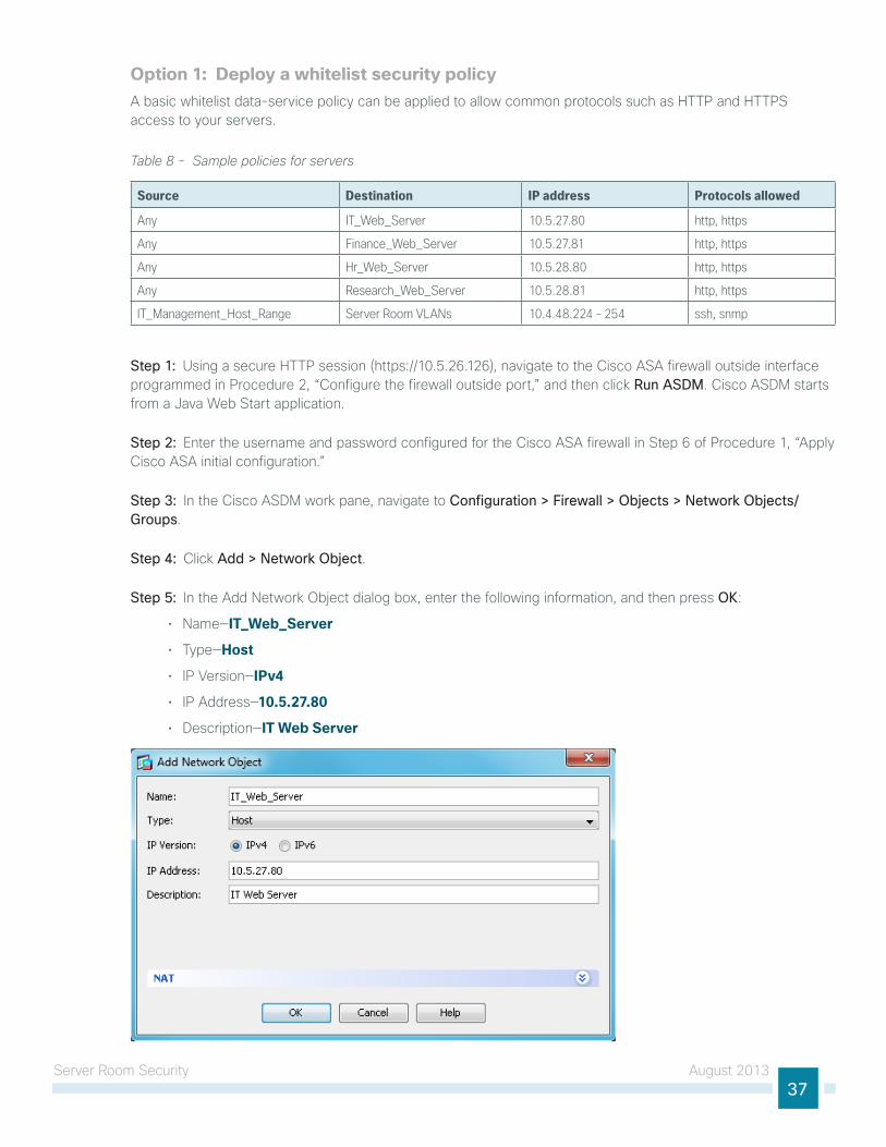
Server Room Security August 201337
Option 1: Deploy a whitelist security policy A basic whitelist data-service policy can be applied to allow common protocols such as httP and httPS access to your servers.
Table 8 - Sample policies for servers
Source Destination IP address Protocols allowed
Any IT_Web_Server 10.5.27.80 http, https
Any Finance_Web_Server 10.5.27.81 http, https
Any Hr_Web_Server 10.5.28.80 http, https
Any Research_Web_Server 10.5.28.81 http, https
IT_Management_Host_Range Server Room VLANs 10.4.48.224 – 254 ssh, snmp
Step 1: using a secure httP session (https://10.5.26.126), navigate to the cisco ASA firewall outside interface programmed in Procedure 2, “configure the firewall outside port,” and then click Run ASDM. cisco ASdM starts from a Java Web Start application.
Step 2: enter the username and password configured for the cisco ASA firewall in Step 6 of Procedure 1, “Apply cisco ASA initial configuration.”
Step 3: in the cisco ASdM work pane, navigate to Configuration > Firewall > Objects > Network Objects/Groups.
Step 4: click Add > Network Object.
Step 5: in the Add network object dialog box, enter the following information, and then press OK:
• name—IT_Web_Server
• type—Host
• iP Version—IPv4
• iP Address—10.5.27.80
• description—IT Web Server
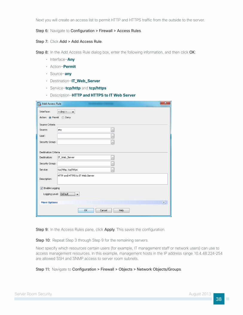
Server Room Security August 201338
next you will create an access list to permit httP and httPS traffic from the outside to the server.
Step 6: navigate to Configuration > Firewall > Access Rules.
Step 7: click Add > Add Access Rule.
Step 8: in the Add Access Rule dialog box, enter the following information, and then click OK:
• interface—Any
• Action—Permit
• Source—any
• destination—IT_Web_Server
• Service—tcp/http and tcp/https
• description—HTTP and HTTPS to IT Web Server
Step 9: in the Access Rules pane, click Apply. this saves the configuration.
Step 10: Repeat Step 3 through Step 9 for the remaining servers.
next specify which resources certain users (for example, it management staff or network users) can use to access management resources. in this example, management hosts in the iP address range 10.4.48.224–254 are allowed SSh and SnMP access to server room subnets.
Step 11: navigate to Configuration > Firewall > Objects > Network Objects/Groups.
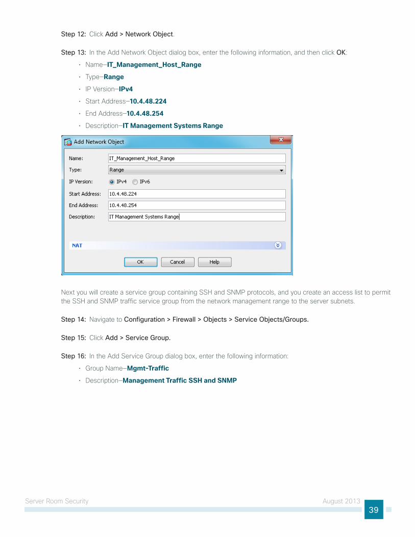
Server Room Security August 201339
Step 12: click Add > Network Object.
Step 13: in the Add network object dialog box, enter the following information, and then click OK:
• name—IT_Management_Host_Range
• type—Range
• iP Version—IPv4
• Start Address—10.4.48.224
• end Address—10.4.48.254
• description—IT Management Systems Range
next you will create a service group containing SSh and SnMP protocols, and you create an access list to permit the SSh and SnMP traffic service group from the network management range to the server subnets.
Step 14: navigate to Configuration > Firewall > Objects > Service Objects/Groups.
Step 15: click Add > Service Group.
Step 16: in the Add Service group dialog box, enter the following information:
• group name—Mgmt-Traffic
• description—Management Traffic SSH and SNMP
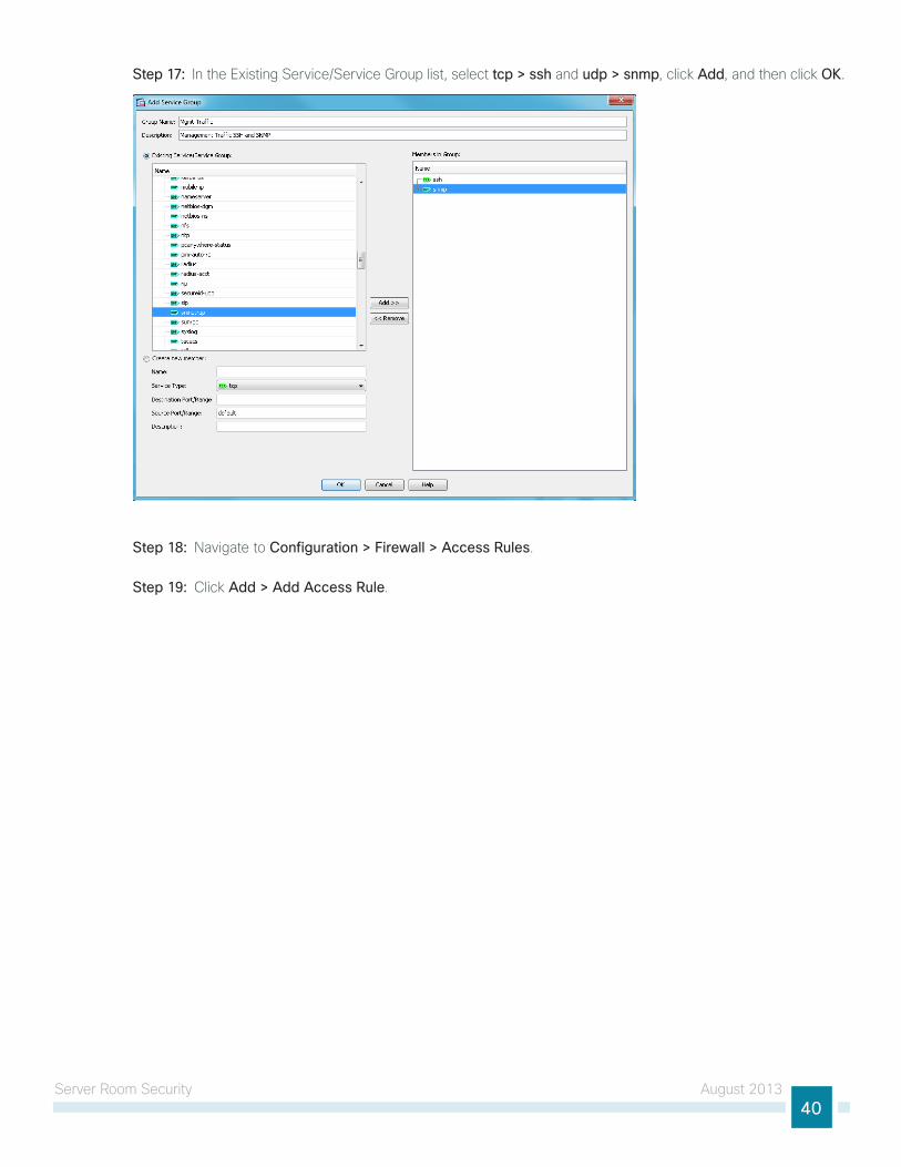
Server Room Security August 201340
Step 17: in the existing Service/Service group list, select tcp > ssh and udp > snmp, click Add, and then click OK.
Step 18: navigate to Configuration > Firewall > Access Rules.
Step 19: click Add > Add Access Rule.
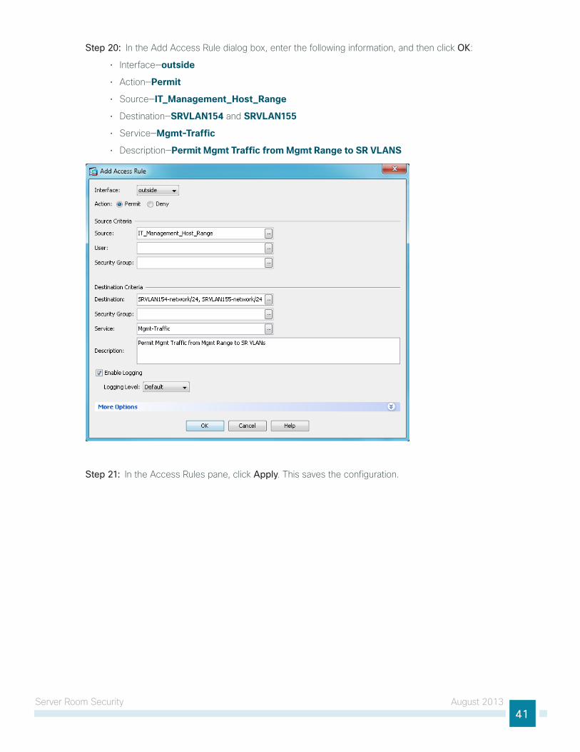
Server Room Security August 201341
Step 20: in the Add Access Rule dialog box, enter the following information, and then click OK:
• interface—outside
• Action—Permit
• Source—IT_Management_Host_Range
• destination—SRVLAN154 and SRVLAN155
• Service—Mgmt-Traffic
• description—Permit Mgmt Traffic from Mgmt Range to SR VLANS
Step 21: in the Access Rules pane, click Apply. this saves the configuration.
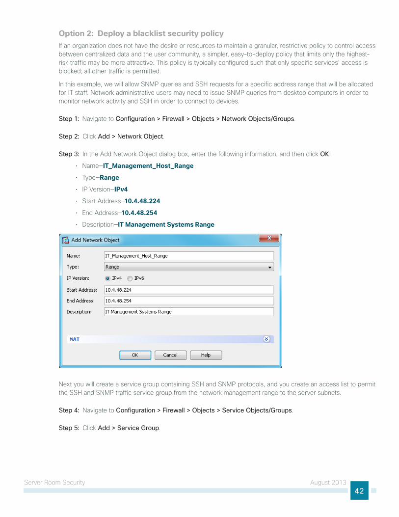
Server Room Security August 201342
Option 2: Deploy a blacklist security policyif an organization does not have the desire or resources to maintain a granular, restrictive policy to control access between centralized data and the user community, a simpler, easy-to-deploy policy that limits only the highest-risk traffic may be more attractive. this policy is typically configured such that only specific services’ access is blocked; all other traffic is permitted.
in this example, we will allow SnMP queries and SSh requests for a specific address range that will be allocated for it staff. network administrative users may need to issue SnMP queries from desktop computers in order to monitor network activity and SSh in order to connect to devices.
Step 1: navigate to Configuration > Firewall > Objects > Network Objects/Groups.
Step 2: click Add > Network Object.
Step 3: in the Add network object dialog box, enter the following information, and then click OK:
• name—IT_Management_Host_Range
• type—Range
• iP Version—IPv4
• Start Address—10.4.48.224
• end Address—10.4.48.254
• description—IT Management Systems Range
next you will create a service group containing SSh and SnMP protocols, and you create an access list to permit the SSh and SnMP traffic service group from the network management range to the server subnets.
Step 4: navigate to Configuration > Firewall > Objects > Service Objects/Groups.
Step 5: click Add > Service Group.
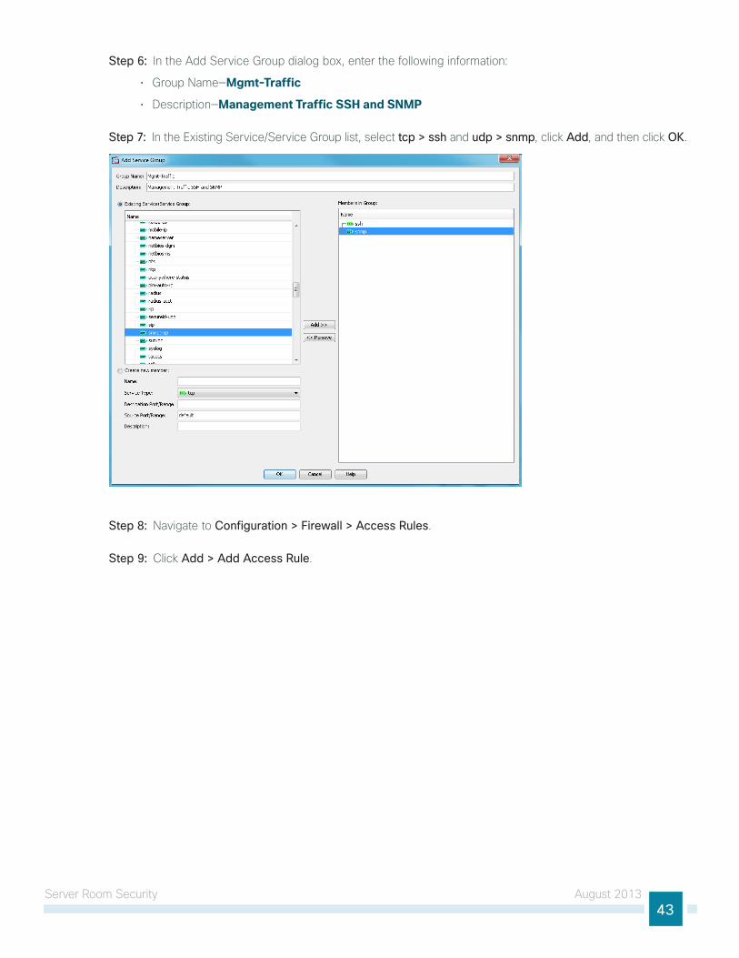
Server Room Security August 201343
Step 6: in the Add Service group dialog box, enter the following information:
• group name—Mgmt-Traffic
• description—Management Traffic SSH and SNMP
Step 7: in the existing Service/Service group list, select tcp > ssh and udp > snmp, click Add, and then click OK.
Step 8: navigate to Configuration > Firewall > Access Rules.
Step 9: click Add > Add Access Rule.
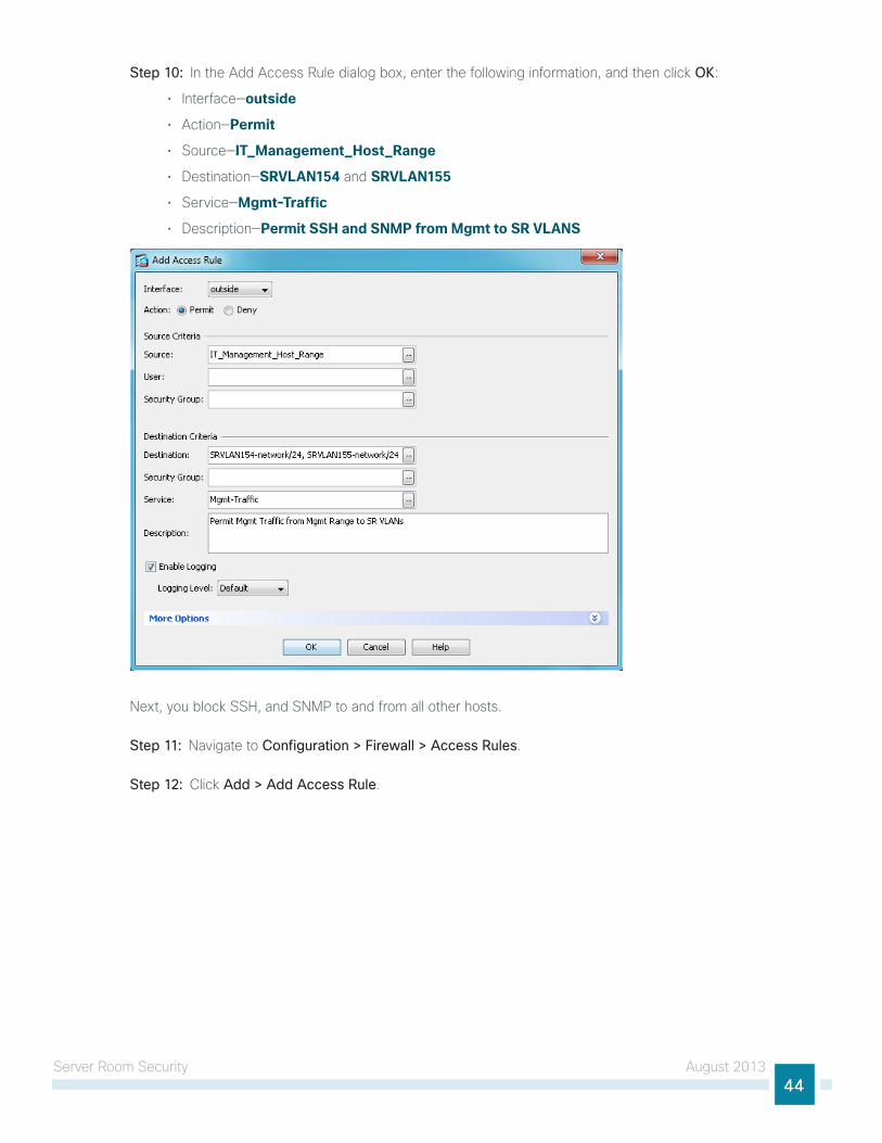
Server Room Security August 201344
Step 10: in the Add Access Rule dialog box, enter the following information, and then click OK:
• interface—outside
• Action—Permit
• Source—IT_Management_Host_Range
• destination—SRVLAN154 and SRVLAN155
• Service—Mgmt-Traffic
• description—Permit SSH and SNMP from Mgmt to SR VLANS
next, you block SSh, and SnMP to and from all other hosts.
Step 11: navigate to Configuration > Firewall > Access Rules.
Step 12: click Add > Add Access Rule.
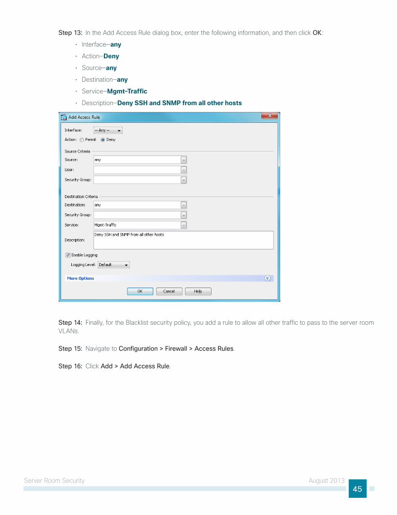
Server Room Security August 201345
Step 13: in the Add Access Rule dialog box, enter the following information, and then click OK:
• interface—any
• Action—Deny
• Source—any
• destination—any
• Service—Mgmt-Traffic
• description—Deny SSH and SNMP from all other hosts
Step 14: Finally, for the Blacklist security policy, you add a rule to allow all other traffic to pass to the server room VlAns.
Step 15: navigate to Configuration > Firewall > Access Rules.
Step 16: click Add > Add Access Rule.
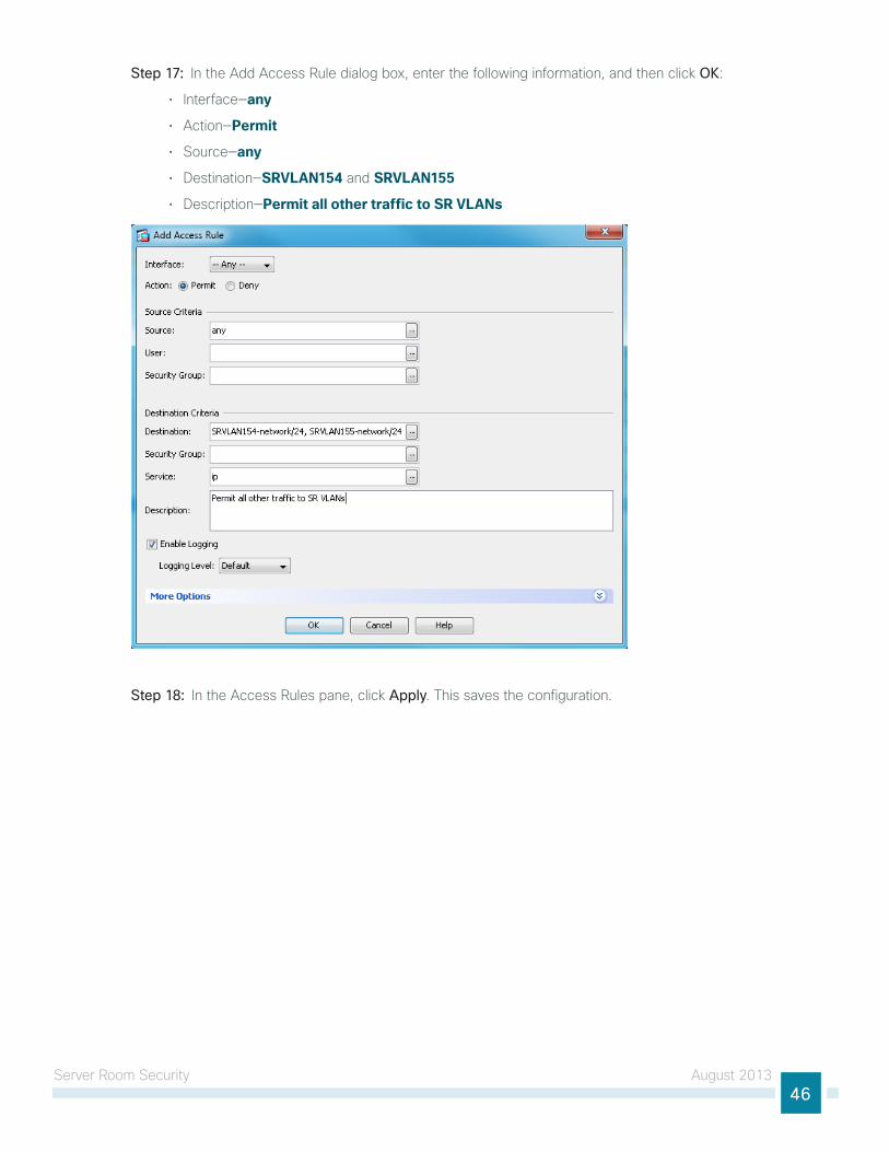
Server Room Security August 201346
Step 17: in the Add Access Rule dialog box, enter the following information, and then click OK:
• interface—any
• Action—Permit
• Source—any
• destination—SRVLAN154 and SRVLAN155
• description—Permit all other traffic to SR VLANs
Step 18: in the Access Rules pane, click Apply. this saves the configuration.
Server Room Security August 201347
Deploying Firewall Intrusion Prevention Systems (IPS)
1. configure the lAn switch access port
2. initialize the iPS module
3. Apply initial configuration
4. complete basic configuration
5. Modify the inline security policy
PR
OC
ESS
From a security standpoint, intrusion detection systems (idS) and intrusion prevention systems (iPS) are complementary to firewalls because firewalls are generally access-control devices that are built to block access to an application or host. in this way, a firewall can be used to remove access to a large number of application ports, reducing the threat to the servers. idS and iPS sensors look for attacks in network and application traffic that is permitted to go through the firewall. if an idS-configured sensor detects an attack, it generates an alert to inform the organization about the activity. An iPS-configured sensor is similar in that it generates alerts due to malicious activity and, additionally, it can apply an action to block the attack before it reaches the destination.
Promiscuous versus Inline Deployment Modesthere are two primary deployment modes when using iPS sensors: promiscuous (idS) or inline (iPS). there are specific reasons for each deployment model, based on risk tolerance and fault tolerance:
• in promiscuous mode (idS), the sensor inspects copies of packets, which prevents it from being able to stop a malicious packet when it sees one. An idS sensor must use another inline enforcement device in order to stop malicious traffic. this means that for activity such as single-packet attacks (for example, slammer worm over user datagram Protocol [udP]), an idS sensor could not prevent the attack from occurring. however, an idS sensor can offer great value when identifying and cleaning up infected hosts.
• in an inline (iPS) deployment, because the packet flow is sent through the sensor and returned to cisco ASA, the sensor inspects the actual data packets. the advantage iPS mode offers is that when the sensor detects malicious behavior, the sensor can simply drop the malicious packet. this allows the iPS device a much greater capacity to actually prevent attacks.
Deployment Considerationsuse idS when you do not want to impact the availability of the network or create latency issues. use iPS when you need higher security than idS can provide and when you need the ability to drop malicious data packets.
the secure server room design using cisco ASA 5500-X Series with iPS implements a policy for iPS, which sends all traffic to the iPS module inline.
your organization may choose an iPS or idS deployment, depending on regulatory and application requirements. it is very easy to initially deploy an idS, or promiscuous, design and then move to iPS after you understand the traffic and performance profile of your network and you are comfortable that production traffic will not be affected.
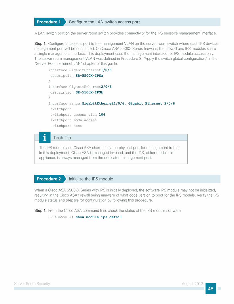
Server Room Security August 201348
Procedure 1 Configure the LAN switch access port
A lAn switch port on the server room switch provides connectivity for the iPS sensor’s management interface.
Step 1: configure an access port to the management VlAn on the server room switch where each iPS device’s management port will be connected. on cisco ASA 5500X Series firewalls, the firewall and iPS modules share a single management interface. this deployment uses the management interface for iPS module access only. the server room management VlAn was defined in Procedure 3, “Apply the switch global configuration,” in the “Server Room ethernet lAn” chapter of this guide.
interface GigabitEthernet1/0/6 description SR-5500X-IPSa!
interface GigabitEthernet2/0/6 description SR-5500X-IPSb!
Interface range GigabitEthernet1/0/6, Gigabit Ethernet 2/0/6 switchport
switchport access vlan 106 switchport mode access
switchport host
the iPS module and cisco ASA share the same physical port for management traffic. in this deployment, cisco ASA is managed in-band, and the iPS, either module or appliance, is always managed from the dedicated management port.
Tech Tip
Procedure 2 Initialize the IPS module
When a cisco ASA 5500-X Series with iPS is initially deployed, the software iPS module may not be initialized, resulting in the cisco ASA firewall being unaware of what code version to boot for the iPS module. Verify the iPS module status and prepare for configuration by following this procedure.
Step 1: From the cisco ASA command line, check the status of the iPS module software.
SR-ASA5500X# show module ips detail
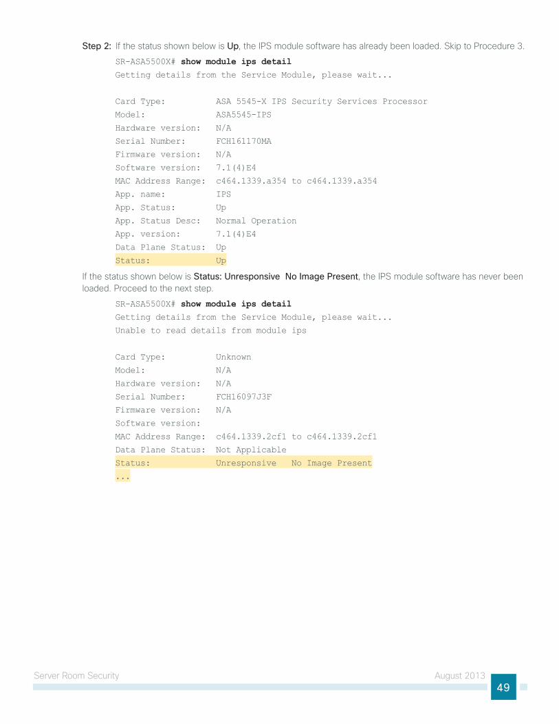
Server Room Security August 201349
Step 2: if the status shown below is Up, the iPS module software has already been loaded. Skip to Procedure 3.
SR-ASA5500X# show module ips detailGetting details from the Service Module, please wait...
Card Type: ASA 5545-X IPS Security Services Processor
Model: ASA5545-IPS
Hardware version: N/A
Serial Number: FCH161170MA
Firmware version: N/A
Software version: 7.1(4)E4
MAC Address Range: c464.1339.a354 to c464.1339.a354
App. name: IPS
App. Status: Up
App. Status Desc: Normal Operation
App. version: 7.1(4)E4
Data Plane Status: Up
Status: Up
if the status shown below is Status: Unresponsive No Image Present, the iPS module software has never been loaded. Proceed to the next step.
SR-ASA5500X# show module ips detailGetting details from the Service Module, please wait...
Unable to read details from module ips
Card Type: Unknown
Model: N/A
Hardware version: N/A
Serial Number: FCH16097J3F
Firmware version: N/A
Software version:
MAC Address Range: c464.1339.2cf1 to c464.1339.2cf1
Data Plane Status: Not Applicable
Status: Unresponsive No Image Present
...
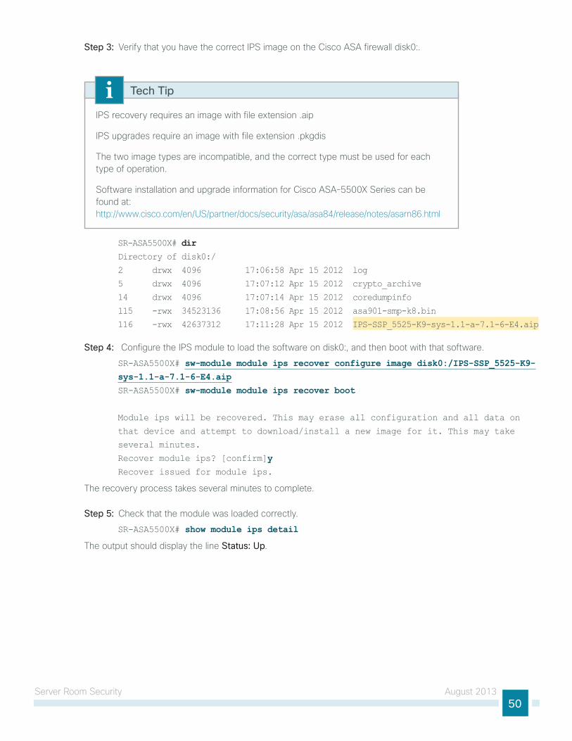
Server Room Security August 201350
Step 3: Verify that you have the correct iPS image on the cisco ASA firewall disk0:.
iPS recovery requires an image with file extension .aip
iPS upgrades require an image with file extension .pkgdis
the two image types are incompatible, and the correct type must be used for each type of operation.
Software installation and upgrade information for cisco ASA-5500X Series can be found at: http://www.cisco.com/en/uS/partner/docs/security/asa/asa84/release/notes/asarn86.html
Tech Tip
SR-ASA5500X# dirDirectory of disk0:/
2 drwx 4096 17:06:58 Apr 15 2012 log
5 drwx 4096 17:07:12 Apr 15 2012 crypto_archive
14 drwx 4096 17:07:14 Apr 15 2012 coredumpinfo
115 -rwx 34523136 17:08:56 Apr 15 2012 asa901-smp-k8.bin
116 -rwx 42637312 17:11:28 Apr 15 2012 IPS-SSP_5525-K9-sys-1.1-a-7.1-6-E4.aip
Step 4: configure the iPS module to load the software on disk0:, and then boot with that software.
SR-ASA5500X# sw-module module ips recover configure image disk0:/IPS-SSP_5525-K9-sys-1.1-a-7.1-6-E4.aipSR-ASA5500X# sw-module module ips recover boot
Module ips will be recovered. This may erase all configuration and all data on
that device and attempt to download/install a new image for it. This may take
several minutes.
Recover module ips? [confirm]yRecover issued for module ips.
the recovery process takes several minutes to complete.
Step 5: check that the module was loaded correctly.
SR-ASA5500X# show module ips detail
the output should display the line Status: Up.
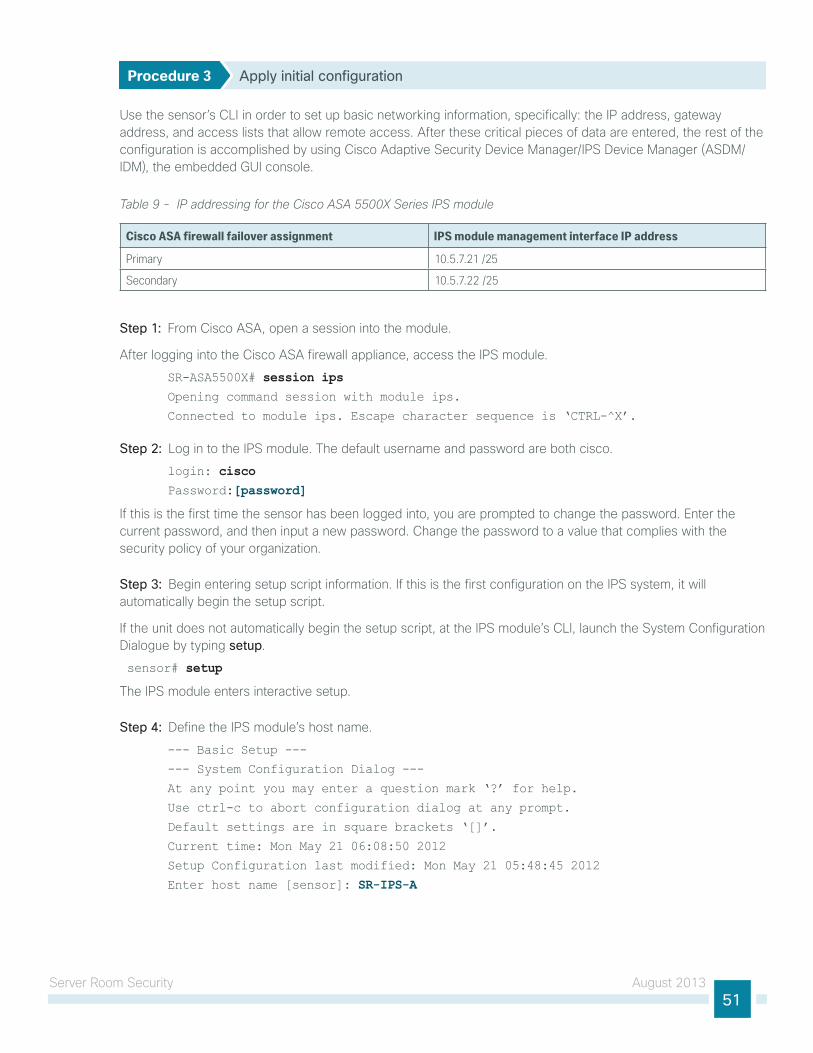
Server Room Security August 201351
Procedure 3 Apply initial configuration
use the sensor’s cli in order to set up basic networking information, specifically: the iP address, gateway address, and access lists that allow remote access. After these critical pieces of data are entered, the rest of the configuration is accomplished by using cisco Adaptive Security device Manager/iPS device Manager (ASdM/idM), the embedded gui console.
Table 9 - IP addressing for the Cisco ASA 5500X Series IPS module
Cisco ASA firewall failover assignment IPS module management interface IP address
Primary 10.5.7.21 /25
Secondary 10.5.7.22 /25
Step 1: From cisco ASA, open a session into the module.
After logging into the cisco ASA firewall appliance, access the iPS module.
SR-ASA5500X# session ipsOpening command session with module ips.
Connected to module ips. Escape character sequence is ‘CTRL-^X’.
Step 2: log in to the iPS module. the default username and password are both cisco.
login: cisco Password:[password]
if this is the first time the sensor has been logged into, you are prompted to change the password. enter the current password, and then input a new password. change the password to a value that complies with the security policy of your organization.
Step 3: Begin entering setup script information. if this is the first configuration on the iPS system, it will automatically begin the setup script.
if the unit does not automatically begin the setup script, at the iPS module’s cli, launch the System configuration dialogue by typing setup.
sensor# setup
the iPS module enters interactive setup.
Step 4: define the iPS module’s host name.
--- Basic Setup ---
--- System Configuration Dialog ---
At any point you may enter a question mark ‘?’ for help.
Use ctrl-c to abort configuration dialog at any prompt.
Default settings are in square brackets ‘[]’.
Current time: Mon May 21 06:08:50 2012
Setup Configuration last modified: Mon May 21 05:48:45 2012
Enter host name [sensor]: SR-IPS-A
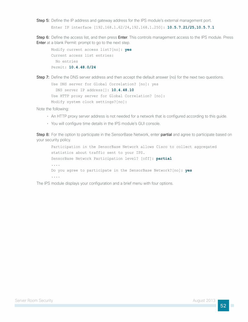
Server Room Security August 201352
Step 5: define the iP address and gateway address for the iPS module’s external management port.
Enter IP interface [192.168.1.62/24,192.168.1.250]: 10.5.7.21/25,10.5.7.1
Step 6: define the access list, and then press Enter. this controls management access to the iPS module. Press Enter at a blank Permit: prompt to go to the next step.
Modify current access list?[no]: yesCurrent access list entries:
No entries
Permit: 10.4.48.0/24
Step 7: define the dnS server address and then accept the default answer (no) for the next two questions.
Use DNS server for Global Correlation? [no]: yes
DNS server IP address[]: 10.4.48.10Use HTTP proxy server for Global Correlation? [no]:
Modify system clock settings?[no]:
note the following:
• An httP proxy server address is not needed for a network that is configured according to this guide.
• you will configure time details in the iPS module’s gui console.
Step 8: For the option to participate in the SensorBase network, enter partial and agree to participate based on your security policy.
Participation in the SensorBase Network allows Cisco to collect aggregated
statistics about traffic sent to your IPS.
SensorBase Network Participation level? [off]: partial ....
Do you agree to participate in the SensorBase Network?[no]: yes....
the iPS module displays your configuration and a brief menu with four options.
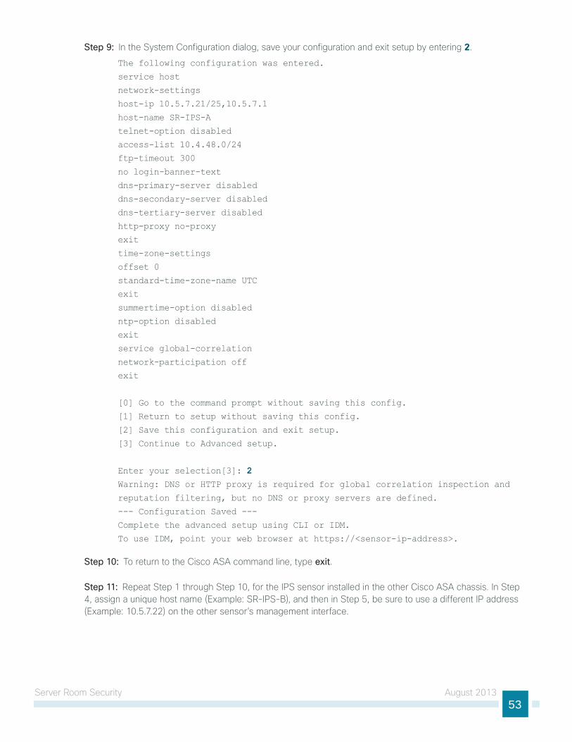
Server Room Security August 201353
Step 9: in the System configuration dialog, save your configuration and exit setup by entering 2.
The following configuration was entered.
service host
network-settings
host-ip 10.5.7.21/25,10.5.7.1
host-name SR-IPS-A
telnet-option disabled
access-list 10.4.48.0/24
ftp-timeout 300
no login-banner-text
dns-primary-server disabled
dns-secondary-server disabled
dns-tertiary-server disabled
http-proxy no-proxy
exit
time-zone-settings
offset 0
standard-time-zone-name UTC
exit
summertime-option disabled
ntp-option disabled
exit
service global-correlation
network-participation off
exit
[0] Go to the command prompt without saving this config.
[1] Return to setup without saving this config.
[2] Save this configuration and exit setup.
[3] Continue to Advanced setup.
Enter your selection[3]: 2Warning: DNS or HTTP proxy is required for global correlation inspection and
reputation filtering, but no DNS or proxy servers are defined.
--- Configuration Saved ---
Complete the advanced setup using CLI or IDM.
To use IDM, point your web browser at https://<sensor-ip-address>.
Step 10: to return to the cisco ASA command line, type exit.
Step 11: Repeat Step 1 through Step 10, for the iPS sensor installed in the other cisco ASA chassis. in Step 4, assign a unique host name (example: SR-iPS-B), and then in Step 5, be sure to use a different iP address (example: 10.5.7.22) on the other sensor’s management interface.
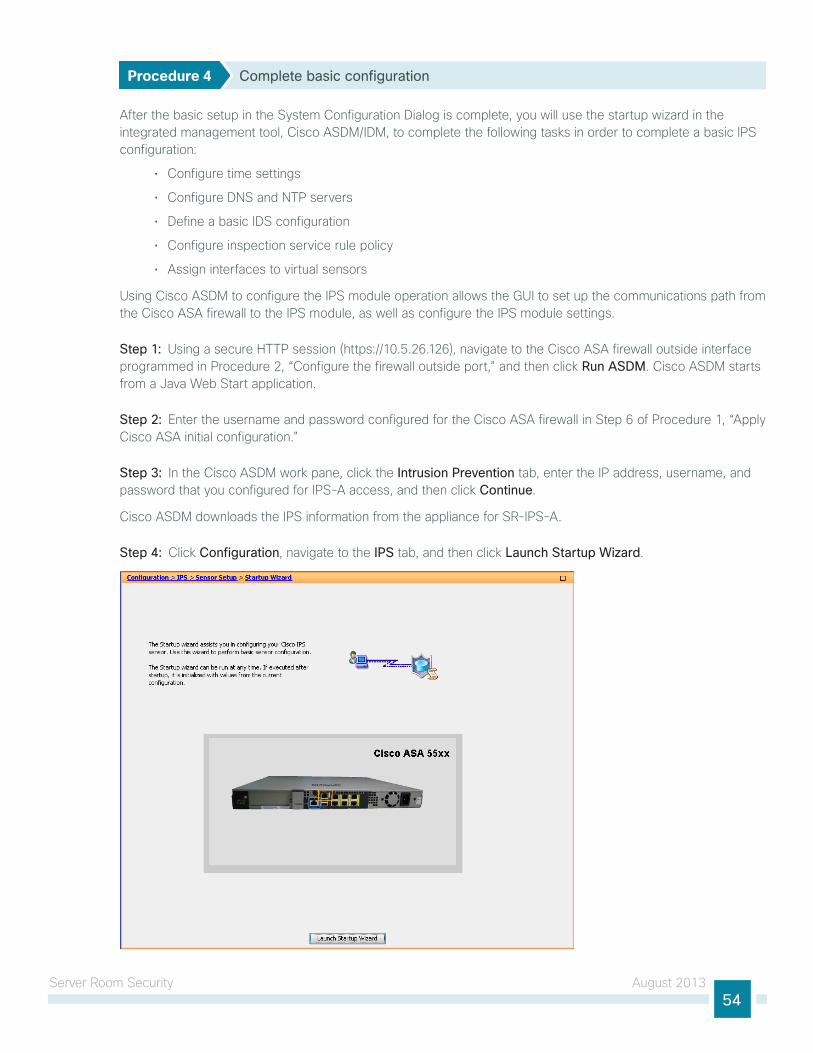
Server Room Security August 201354
Procedure 4 Complete basic configuration
After the basic setup in the System configuration dialog is complete, you will use the startup wizard in the integrated management tool, cisco ASdM/idM, to complete the following tasks in order to complete a basic iPS configuration:
• configure time settings
• configure dnS and ntP servers
• define a basic idS configuration
• configure inspection service rule policy
• Assign interfaces to virtual sensors
using cisco ASdM to configure the iPS module operation allows the gui to set up the communications path from the cisco ASA firewall to the iPS module, as well as configure the iPS module settings.
Step 1: using a secure httP session (https://10.5.26.126), navigate to the cisco ASA firewall outside interface programmed in Procedure 2, “configure the firewall outside port,” and then click Run ASDM. cisco ASdM starts from a Java Web Start application.
Step 2: enter the username and password configured for the cisco ASA firewall in Step 6 of Procedure 1, “Apply cisco ASA initial configuration.”
Step 3: in the cisco ASdM work pane, click the Intrusion Prevention tab, enter the iP address, username, and password that you configured for iPS-A access, and then click Continue.
cisco ASdM downloads the iPS information from the appliance for SR-iPS-A.
Step 4: click Configuration, navigate to the IPS tab, and then click Launch Startup Wizard.
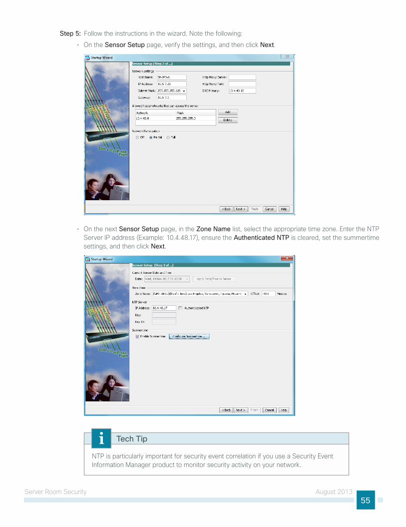
Server Room Security August 201355
Step 5: Follow the instructions in the wizard. note the following:
• on the Sensor Setup page, verify the settings, and then click Next.
• on the next Sensor Setup page, in the Zone Name list, select the appropriate time zone. enter the ntP Server iP address (example: 10.4.48.17), ensure the Authenticated NTP is cleared, set the summertime settings, and then click Next.
ntP is particularly important for security event correlation if you use a Security event information Manager product to monitor security activity on your network.
Tech Tip
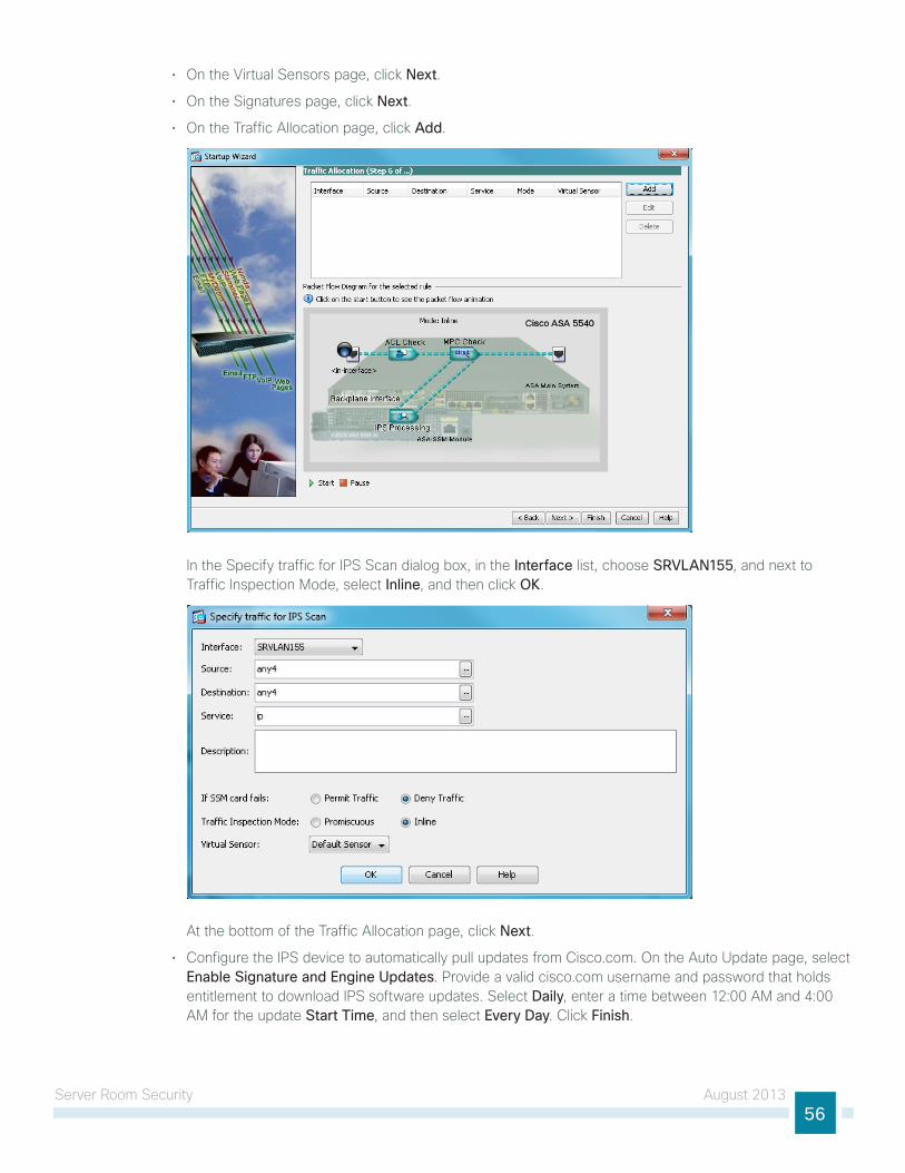
Server Room Security August 201356
• on the Virtual Sensors page, click Next.
• on the Signatures page, click Next.
• on the traffic Allocation page, click Add.
in the Specify traffic for iPS Scan dialog box, in the Interface list, choose SRVLAN155, and next to traffic inspection Mode, select Inline, and then click OK.
At the bottom of the traffic Allocation page, click Next.
• configure the iPS device to automatically pull updates from cisco.com. on the Auto update page, select Enable Signature and Engine Updates. Provide a valid cisco.com username and password that holds entitlement to download iPS software updates. Select Daily, enter a time between 12:00 AM and 4:00 AM for the update Start Time, and then select Every Day. click Finish.
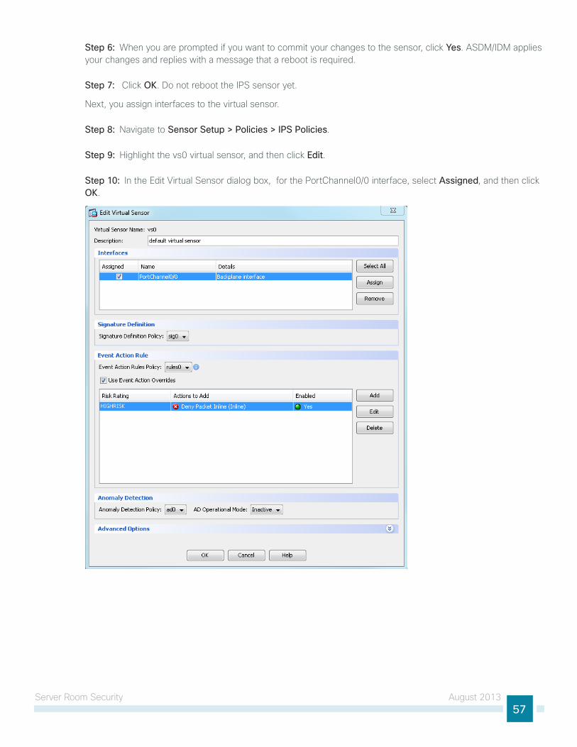
Server Room Security August 201357
Step 6: When you are prompted if you want to commit your changes to the sensor, click Yes. ASdM/idM applies your changes and replies with a message that a reboot is required.
Step 7: click OK. do not reboot the iPS sensor yet.
next, you assign interfaces to the virtual sensor.
Step 8: navigate to Sensor Setup > Policies > IPS Policies.
Step 9: highlight the vs0 virtual sensor, and then click Edit.
Step 10: in the edit Virtual Sensor dialog box, for the Portchannel0/0 interface, select Assigned, and then click OK.
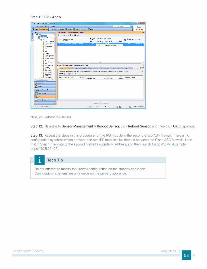
Server Room Security August 201358
Step 11: click Apply.
next, you reboot the sensor.
Step 12: navigate to Sensor Management > Reboot Sensor, click Reboot Sensor, and then click OK to approve.
Step 13: Repeat the steps in this procedure for the iPS module in the second cisco ASA firewall. there is no configuration synchronization between the two iPS modules like there is between the cisco ASA firewalls. note that in Step 1, navigate to the second firewall’s outside iP address, and then launch cisco ASdM. (example: https://10.5.26.125).
do not attempt to modify the firewall configuration on the standby appliance. configuration changes are only made on the primary appliance.
Tech Tip
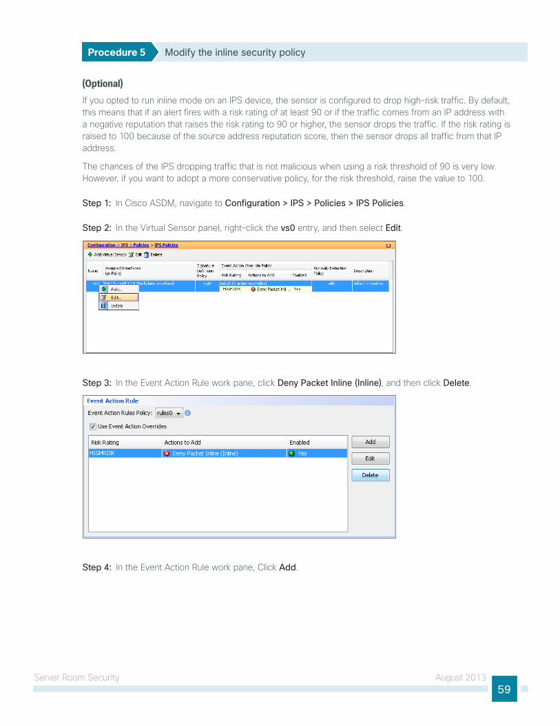
Server Room Security August 201359
Procedure 5 Modify the inline security policy
(Optional)if you opted to run inline mode on an iPS device, the sensor is configured to drop high-risk traffic. By default, this means that if an alert fires with a risk rating of at least 90 or if the traffic comes from an iP address with a negative reputation that raises the risk rating to 90 or higher, the sensor drops the traffic. if the risk rating is raised to 100 because of the source address reputation score, then the sensor drops all traffic from that iP address.
the chances of the iPS dropping traffic that is not malicious when using a risk threshold of 90 is very low. however, if you want to adopt a more conservative policy, for the risk threshold, raise the value to 100.
Step 1: in cisco ASdM, navigate to Configuration > IPS > Policies > IPS Policies.
Step 2: in the Virtual Sensor panel, right-click the vs0 entry, and then select Edit.
Step 3: in the event Action Rule work pane, click Deny Packet Inline (Inline), and then click Delete.
Step 4: in the event Action Rule work pane, click Add.
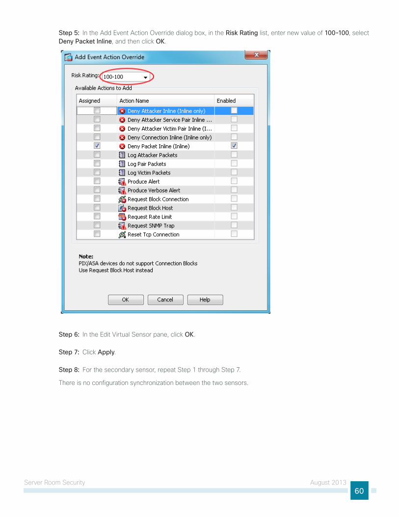
Server Room Security August 201360
Step 5: in the Add event Action override dialog box, in the Risk Rating list, enter new value of 100-100, select Deny Packet Inline, and then click OK.
Step 6: in the edit Virtual Sensor pane, click OK.
Step 7: click Apply.
Step 8: For the secondary sensor, repeat Step 1 through Step 7.
there is no configuration synchronization between the two sensors.
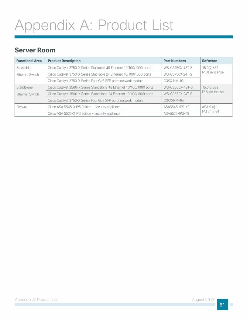
Appendix A: Product list August 201361
Appendix A: Product listServer Room
Functional Area Product Description Part Numbers Software
Stackable
Ethernet Switch
Cisco Catalyst 3750-X Series Stackable 48 Ethernet 10/100/1000 ports WS-C3750X-48T-S 15.0(2)SE2 IP Base licenseCisco Catalyst 3750-X Series Stackable 24 Ethernet 10/100/1000 ports WS-C3750X-24T-S
Cisco Catalyst 3750-X Series Four GbE SFP ports network module C3KX-NM-1G
Standalone
Ethernet Switch
Cisco Catalyst 3560-X Series Standalone 48 Ethernet 10/100/1000 ports WS-C3560X-48T-S 15.0(2)SE2 IP Base licenseCisco Catalyst 3560-X Series Standalone 24 Ethernet 10/100/1000 ports WS-C3560X-24T-S
Cisco Catalyst 3750-X Series Four GbE SFP ports network module C3KX-NM-1G
Firewall Cisco ASA 5545-X IPS Edition - security appliance ASA5545-IPS-K9 ASA 9.0(1) IPS 7.1(7)E4Cisco ASA 5525-X IPS Edition - security appliance ASA5525-IPS-K9
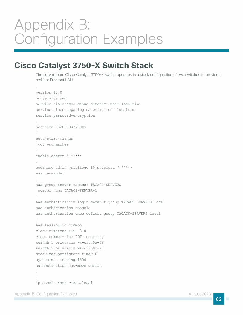
Appendix B: configuration examples August 201362
Appendix B: configuration examples
Cisco Catalyst 3750-X Switch Stackthe server room cisco catalyst 3750-X switch operates in a stack configuration of two switches to provide a resilient ethernet lAn.
!
version 15.0
no service pad
service timestamps debug datetime msec localtime
service timestamps log datetime msec localtime
service password-encryption
!
hostname RS200-SR3750Xy
!
boot-start-marker
boot-end-marker
!
enable secret 5 *****
!
username admin privilege 15 password 7 *****
aaa new-model
!
aaa group server tacacs+ TACACS-SERVERS
server name TACACS-SERVER-1
!
aaa authentication login default group TACACS-SERVERS local
aaa authorization console
aaa authorization exec default group TACACS-SERVERS local
!
aaa session-id common
clock timezone PST -8 0
clock summer-time PDT recurring
switch 1 provision ws-c3750x-48
switch 2 provision ws-c3750x-48
stack-mac persistent timer 0
system mtu routing 1500
authentication mac-move permit
!
!
ip domain-name cisco.local

Appendix B: configuration examples August 201363
ip name-server 10.4.48.10
vtp mode transparent
udld enable
!
mls qos map policed-dscp 0 10 18 to 8
mls qos map cos-dscp 0 8 16 24 32 46 48 56
mls qos srr-queue input bandwidth 70 30
mls qos srr-queue input threshold 1 80 90
mls qos srr-queue input priority-queue 2 bandwidth 30
mls qos srr-queue input cos-map queue 1 threshold 2 3
mls qos srr-queue input cos-map queue 1 threshold 3 6 7
mls qos srr-queue input cos-map queue 2 threshold 1 4
mls qos srr-queue input dscp-map queue 1 threshold 2 24
mls qos srr-queue input dscp-map queue 1 threshold 3 48 49 50 51 52 53 54 55
mls qos srr-queue input dscp-map queue 1 threshold 3 56 57 58 59 60 61 62 63
mls qos srr-queue input dscp-map queue 2 threshold 3 32 33 40 41 42 43 44 45
mls qos srr-queue input dscp-map queue 2 threshold 3 46 47
mls qos srr-queue output cos-map queue 1 threshold 3 4 5
mls qos srr-queue output cos-map queue 2 threshold 1 2
mls qos srr-queue output cos-map queue 2 threshold 2 3
mls qos srr-queue output cos-map queue 2 threshold 3 6 7
mls qos srr-queue output cos-map queue 3 threshold 3 0
mls qos srr-queue output cos-map queue 4 threshold 3 1
mls qos srr-queue output dscp-map queue 1 threshold 3 32 33 40 41 42 43 44 45
mls qos srr-queue output dscp-map queue 1 threshold 3 46 47
mls qos srr-queue output dscp-map queue 2 threshold 1 16 17 18 19 20 21 22 23
mls qos srr-queue output dscp-map queue 2 threshold 1 26 27 28 29 30 31 34 35
mls qos srr-queue output dscp-map queue 2 threshold 1 36 37 38 39
mls qos srr-queue output dscp-map queue 2 threshold 2 24
mls qos srr-queue output dscp-map queue 2 threshold 3 48 49 50 51 52 53 54 55
mls qos srr-queue output dscp-map queue 2 threshold 3 56 57 58 59 60 61 62 63
mls qos srr-queue output dscp-map queue 3 threshold 3 0 1 2 3 4 5 6 7
mls qos srr-queue output dscp-map queue 4 threshold 1 8 9 11 13 15
mls qos srr-queue output dscp-map queue 4 threshold 2 10 12 14
mls qos queue-set output 1 threshold 1 100 100 50 200
mls qos queue-set output 1 threshold 2 125 125 100 400
mls qos queue-set output 1 threshold 3 100 100 100 3200
mls qos queue-set output 1 threshold 4 60 150 50 200
mls qos queue-set output 1 buffers 15 25 40 20
mls qos
!
crypto pki trustpoint TP-self-signed-251756672
enrollment selfsigned
subject-name cn=IOS-Self-Signed-Certificate-251756672
revocation-check none
rsakeypair TP-self-signed-251756672
!
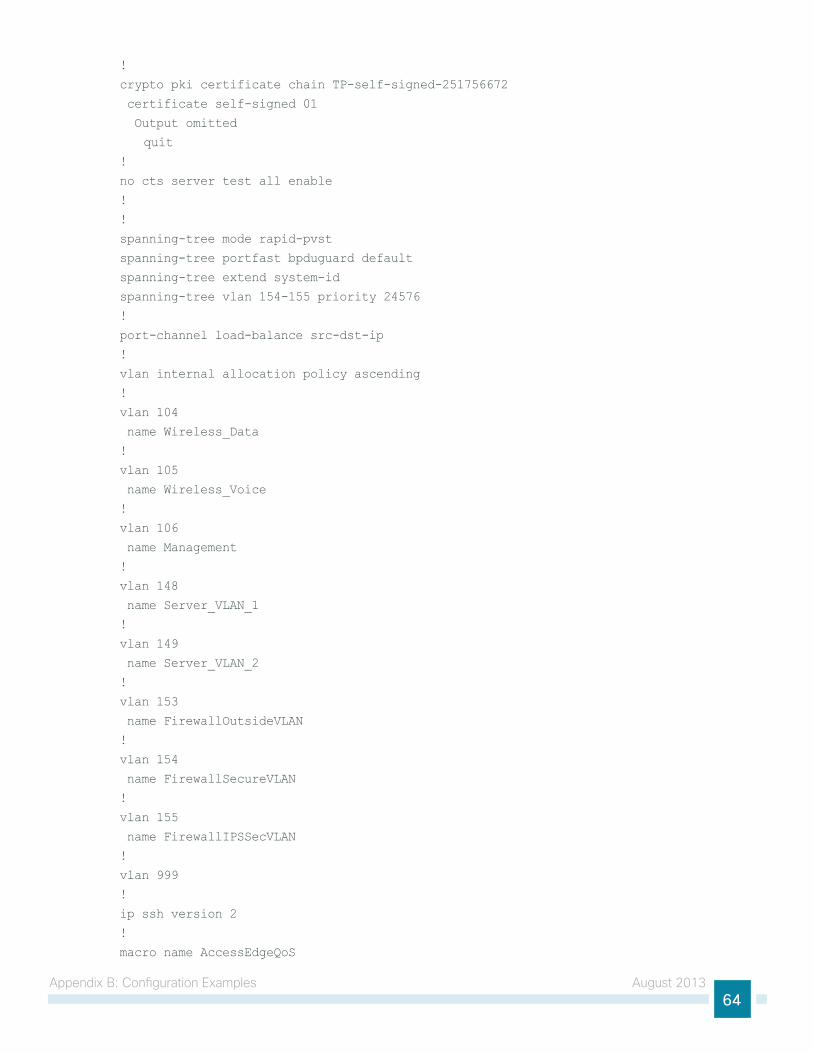
Appendix B: configuration examples August 201364
!
crypto pki certificate chain TP-self-signed-251756672
certificate self-signed 01
Output omitted
quit
!
no cts server test all enable
!
!
spanning-tree mode rapid-pvst
spanning-tree portfast bpduguard default
spanning-tree extend system-id
spanning-tree vlan 154-155 priority 24576
!
port-channel load-balance src-dst-ip
!
vlan internal allocation policy ascending
!
vlan 104
name Wireless_Data
!
vlan 105
name Wireless_Voice
!
vlan 106
name Management
!
vlan 148
name Server_VLAN_1
!
vlan 149
name Server_VLAN_2
!
vlan 153
name FirewallOutsideVLAN
!
vlan 154
name FirewallSecureVLAN
!
vlan 155
name FirewallIPSSecVLAN
!
vlan 999
!
ip ssh version 2
!
macro name AccessEdgeQoS
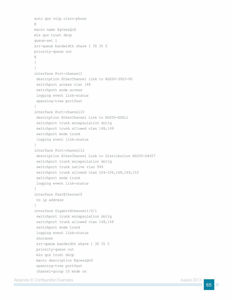
Appendix B: configuration examples August 201365
auto qos voip cisco-phone
@
macro name EgressQoS
mls qos trust dscp
queue-set 1
srr-queue bandwidth share 1 30 35 5
priority-queue out
@
!
!
interface Port-channel1
description EtherChannel link to RS200-3925-VG
switchport access vlan 148
switchport mode access
logging event link-status
spanning-tree portfast
!
interface Port-channel10
description EtherChannel Link to RS200-ESXi1
switchport trunk encapsulation dot1q
switchport trunk allowed vlan 148,149
switchport mode trunk
logging event link-status
!
interface Port-channel12
description EtherChannel Link to Distribution RS200-D4507
switchport trunk encapsulation dot1q
switchport trunk native vlan 999
switchport trunk allowed vlan 104-106,148,149,153
switchport mode trunk
logging event link-status
!
interface FastEthernet0
no ip address
!
interface GigabitEthernet1/0/1
switchport trunk encapsulation dot1q
switchport trunk allowed vlan 148,149
switchport mode trunk
logging event link-status
shutdown
srr-queue bandwidth share 1 30 35 5
priority-queue out
mls qos trust dscp
macro description EgressQoS
spanning-tree portfast
channel-group 10 mode on
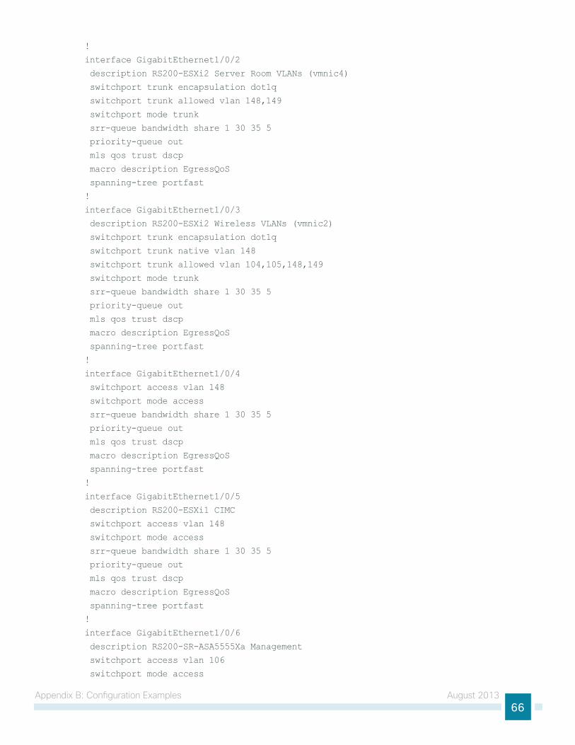
Appendix B: configuration examples August 201366
!
interface GigabitEthernet1/0/2
description RS200-ESXi2 Server Room VLANs (vmnic4)
switchport trunk encapsulation dot1q
switchport trunk allowed vlan 148,149
switchport mode trunk
srr-queue bandwidth share 1 30 35 5
priority-queue out
mls qos trust dscp
macro description EgressQoS
spanning-tree portfast
!
interface GigabitEthernet1/0/3
description RS200-ESXi2 Wireless VLANs (vmnic2)
switchport trunk encapsulation dot1q
switchport trunk native vlan 148
switchport trunk allowed vlan 104,105,148,149
switchport mode trunk
srr-queue bandwidth share 1 30 35 5
priority-queue out
mls qos trust dscp
macro description EgressQoS
spanning-tree portfast
!
interface GigabitEthernet1/0/4
switchport access vlan 148
switchport mode access
srr-queue bandwidth share 1 30 35 5
priority-queue out
mls qos trust dscp
macro description EgressQoS
spanning-tree portfast
!
interface GigabitEthernet1/0/5
description RS200-ESXi1 CIMC
switchport access vlan 148
switchport mode access
srr-queue bandwidth share 1 30 35 5
priority-queue out
mls qos trust dscp
macro description EgressQoS
spanning-tree portfast
!
interface GigabitEthernet1/0/6
description RS200-SR-ASA5555Xa Management
switchport access vlan 106
switchport mode access
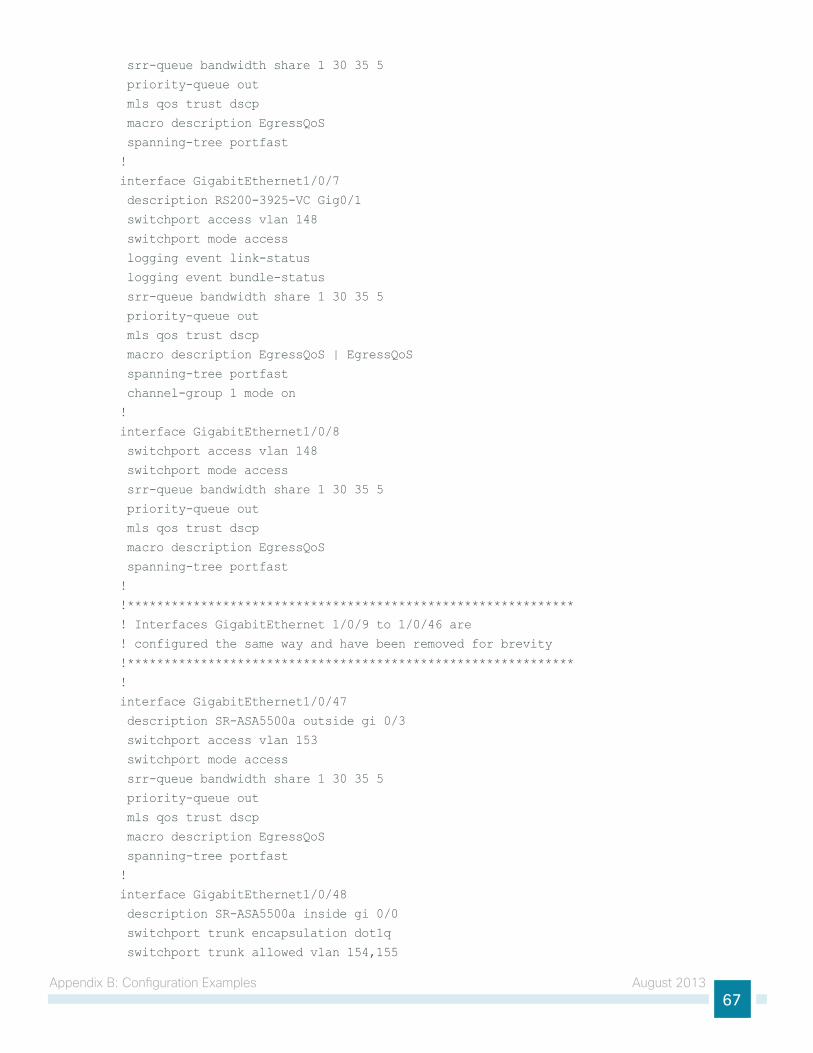
Appendix B: configuration examples August 201367
srr-queue bandwidth share 1 30 35 5
priority-queue out
mls qos trust dscp
macro description EgressQoS
spanning-tree portfast
!
interface GigabitEthernet1/0/7
description RS200-3925-VC Gig0/1
switchport access vlan 148
switchport mode access
logging event link-status
logging event bundle-status
srr-queue bandwidth share 1 30 35 5
priority-queue out
mls qos trust dscp
macro description EgressQoS | EgressQoS
spanning-tree portfast
channel-group 1 mode on
!
interface GigabitEthernet1/0/8
switchport access vlan 148
switchport mode access
srr-queue bandwidth share 1 30 35 5
priority-queue out
mls qos trust dscp
macro description EgressQoS
spanning-tree portfast
!
!*************************************************************
! Interfaces GigabitEthernet 1/0/9 to 1/0/46 are
! configured the same way and have been removed for brevity
!*************************************************************
!
interface GigabitEthernet1/0/47
description SR-ASA5500a outside gi 0/3
switchport access vlan 153
switchport mode access
srr-queue bandwidth share 1 30 35 5
priority-queue out
mls qos trust dscp
macro description EgressQoS
spanning-tree portfast
!
interface GigabitEthernet1/0/48
description SR-ASA5500a inside gi 0/0
switchport trunk encapsulation dot1q
switchport trunk allowed vlan 154,155
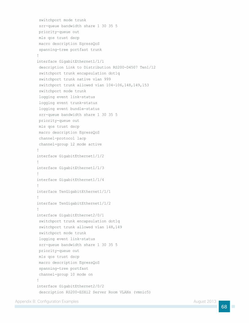
Appendix B: configuration examples August 201368
switchport mode trunk
srr-queue bandwidth share 1 30 35 5
priority-queue out
mls qos trust dscp
macro description EgressQoS
spanning-tree portfast trunk
!
interface GigabitEthernet1/1/1
description Link to Distribution RS200-D4507 Ten1/12
switchport trunk encapsulation dot1q
switchport trunk native vlan 999
switchport trunk allowed vlan 104-106,148,149,153
switchport mode trunk
logging event link-status
logging event trunk-status
logging event bundle-status
srr-queue bandwidth share 1 30 35 5
priority-queue out
mls qos trust dscp
macro description EgressQoS
channel-protocol lacp
channel-group 12 mode active
!
interface GigabitEthernet1/1/2
!
interface GigabitEthernet1/1/3
!
interface GigabitEthernet1/1/4
!
interface TenGigabitEthernet1/1/1
!
interface TenGigabitEthernet1/1/2
!
interface GigabitEthernet2/0/1
switchport trunk encapsulation dot1q
switchport trunk allowed vlan 148,149
switchport mode trunk
logging event link-status
srr-queue bandwidth share 1 30 35 5
priority-queue out
mls qos trust dscp
macro description EgressQoS
spanning-tree portfast
channel-group 10 mode on
!
interface GigabitEthernet2/0/2
description RS200-ESXi2 Server Room VLANs (vmnic5)
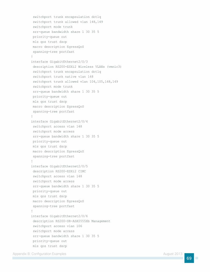
Appendix B: configuration examples August 201369
switchport trunk encapsulation dot1q
switchport trunk allowed vlan 148,149
switchport mode trunk
srr-queue bandwidth share 1 30 35 5
priority-queue out
mls qos trust dscp
macro description EgressQoS
spanning-tree portfast
!
interface GigabitEthernet2/0/3
description RS200-ESXi2 Wireless VLANs (vmnic3)
switchport trunk encapsulation dot1q
switchport trunk native vlan 148
switchport trunk allowed vlan 104,105,148,149
switchport mode trunk
srr-queue bandwidth share 1 30 35 5
priority-queue out
mls qos trust dscp
macro description EgressQoS
spanning-tree portfast
!
interface GigabitEthernet2/0/4
switchport access vlan 148
switchport mode access
srr-queue bandwidth share 1 30 35 5
priority-queue out
mls qos trust dscp
macro description EgressQoS
spanning-tree portfast
!
interface GigabitEthernet2/0/5
description RS200-ESXi2 CIMC
switchport access vlan 148
switchport mode access
srr-queue bandwidth share 1 30 35 5
priority-queue out
mls qos trust dscp
macro description EgressQoS
spanning-tree portfast
!
interface GigabitEthernet2/0/6
description RS200-SR-ASA5555Xb Management
switchport access vlan 106
switchport mode access
srr-queue bandwidth share 1 30 35 5
priority-queue out
mls qos trust dscp
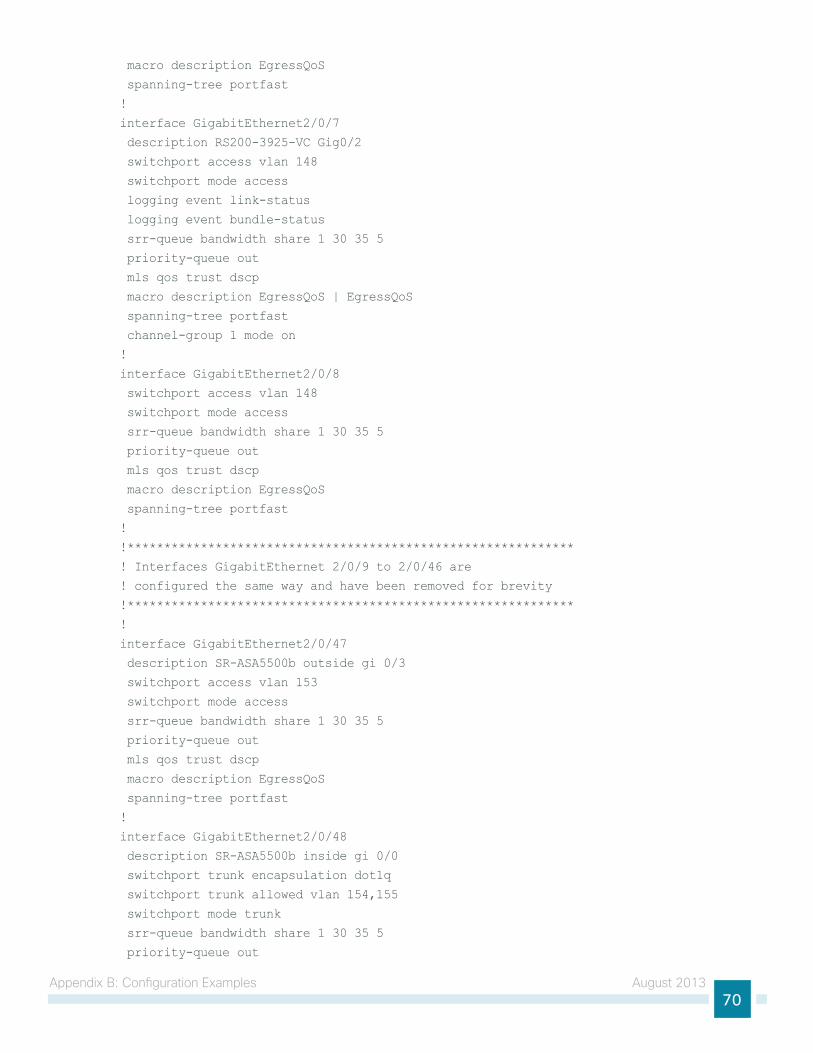
Appendix B: configuration examples August 201370
macro description EgressQoS
spanning-tree portfast
!
interface GigabitEthernet2/0/7
description RS200-3925-VC Gig0/2
switchport access vlan 148
switchport mode access
logging event link-status
logging event bundle-status
srr-queue bandwidth share 1 30 35 5
priority-queue out
mls qos trust dscp
macro description EgressQoS | EgressQoS
spanning-tree portfast
channel-group 1 mode on
!
interface GigabitEthernet2/0/8
switchport access vlan 148
switchport mode access
srr-queue bandwidth share 1 30 35 5
priority-queue out
mls qos trust dscp
macro description EgressQoS
spanning-tree portfast
!
!*************************************************************
! Interfaces GigabitEthernet 2/0/9 to 2/0/46 are
! configured the same way and have been removed for brevity
!*************************************************************
!
interface GigabitEthernet2/0/47
description SR-ASA5500b outside gi 0/3
switchport access vlan 153
switchport mode access
srr-queue bandwidth share 1 30 35 5
priority-queue out
mls qos trust dscp
macro description EgressQoS
spanning-tree portfast
!
interface GigabitEthernet2/0/48
description SR-ASA5500b inside gi 0/0
switchport trunk encapsulation dot1q
switchport trunk allowed vlan 154,155
switchport mode trunk
srr-queue bandwidth share 1 30 35 5
priority-queue out
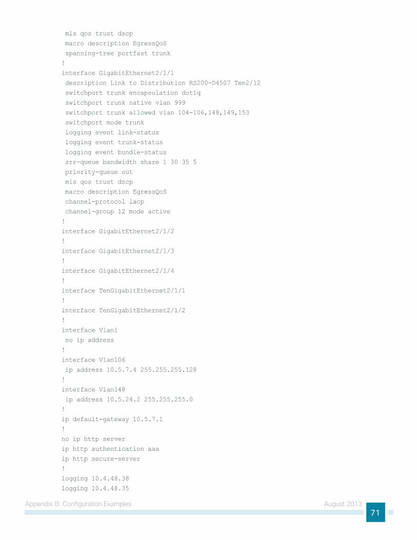
Appendix B: configuration examples August 201371
mls qos trust dscp
macro description EgressQoS
spanning-tree portfast trunk
!
interface GigabitEthernet2/1/1
description Link to Distribution RS200-D4507 Ten2/12
switchport trunk encapsulation dot1q
switchport trunk native vlan 999
switchport trunk allowed vlan 104-106,148,149,153
switchport mode trunk
logging event link-status
logging event trunk-status
logging event bundle-status
srr-queue bandwidth share 1 30 35 5
priority-queue out
mls qos trust dscp
macro description EgressQoS
channel-protocol lacp
channel-group 12 mode active
!
interface GigabitEthernet2/1/2
!
interface GigabitEthernet2/1/3
!
interface GigabitEthernet2/1/4
!
interface TenGigabitEthernet2/1/1
!
interface TenGigabitEthernet2/1/2
!
interface Vlan1
no ip address
!
interface Vlan106
ip address 10.5.7.4 255.255.255.128
!
interface Vlan148
ip address 10.5.24.2 255.255.255.0
!
ip default-gateway 10.5.7.1
!
no ip http server
ip http authentication aaa
ip http secure-server
!
logging 10.4.48.38
logging 10.4.48.35
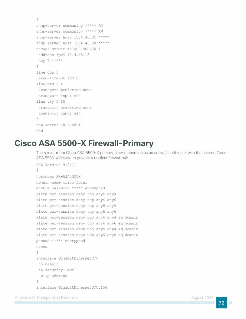
Appendix B: configuration examples August 201372
!
snmp-server community ***** RO
snmp-server community ***** RW
snmp-server host 10.4.48.35 *****
snmp-server host 10.4.48.38 *****
tacacs server TACACS-SERVER-1
address ipv4 10.4.48.15
key 7 *****
!
line con 0
exec-timeout 120 0
line vty 0 4
transport preferred none
transport input ssh
line vty 5 15
transport preferred none
transport input ssh
!
ntp server 10.4.48.17
end
Cisco ASA 5500-X Firewall-Primarythe server room cisco ASA 5500-X primary firewall operates as an active/standby pair with the second cisco ASA 5500-X firewall to provide a resilient firewall pair.
ASA Version 9.0(1)
!
hostname SR-ASA5500X
domain-name cisco.local
enable password ***** encrypted
xlate per-session deny tcp any4 any4
xlate per-session deny tcp any4 any6
xlate per-session deny tcp any6 any4
xlate per-session deny tcp any6 any6
xlate per-session deny udp any4 any4 eq domain
xlate per-session deny udp any4 any6 eq domain
xlate per-session deny udp any6 any4 eq domain
xlate per-session deny udp any6 any6 eq domain
passwd ***** encrypted
names
!
interface GigabitEthernet0/0
no nameif
no security-level
no ip address
!
interface GigabitEthernet0/0.154
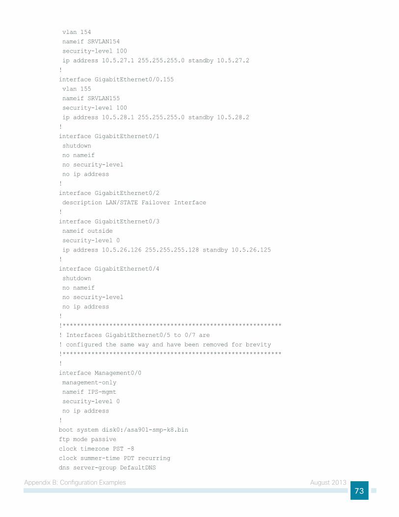
Appendix B: configuration examples August 201373
vlan 154
nameif SRVLAN154
security-level 100
ip address 10.5.27.1 255.255.255.0 standby 10.5.27.2
!
interface GigabitEthernet0/0.155
vlan 155
nameif SRVLAN155
security-level 100
ip address 10.5.28.1 255.255.255.0 standby 10.5.28.2
!
interface GigabitEthernet0/1
shutdown
no nameif
no security-level
no ip address
!
interface GigabitEthernet0/2
description LAN/STATE Failover Interface
!
interface GigabitEthernet0/3
nameif outside
security-level 0
ip address 10.5.26.126 255.255.255.128 standby 10.5.26.125
!
interface GigabitEthernet0/4
shutdown
no nameif
no security-level
no ip address
!
!*************************************************************
! Interfaces GigabitEthernet0/5 to 0/7 are
! configured the same way and have been removed for brevity
!*************************************************************
!
interface Management0/0
management-only
nameif IPS-mgmt
security-level 0
no ip address
!
boot system disk0:/asa901-smp-k8.bin
ftp mode passive
clock timezone PST -8
clock summer-time PDT recurring
dns server-group DefaultDNS
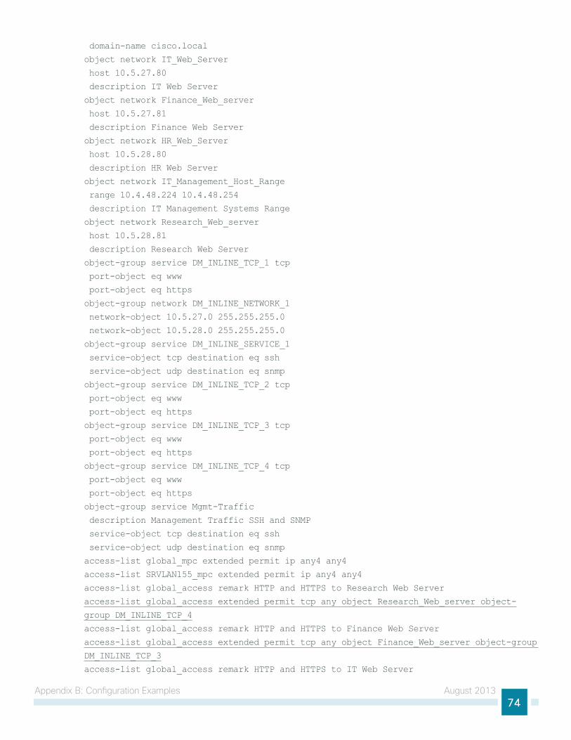
Appendix B: configuration examples August 201374
domain-name cisco.local
object network IT_Web_Server
host 10.5.27.80
description IT Web Server
object network Finance_Web_server
host 10.5.27.81
description Finance Web Server
object network HR_Web_Server
host 10.5.28.80
description HR Web Server
object network IT_Management_Host_Range
range 10.4.48.224 10.4.48.254
description IT Management Systems Range
object network Research_Web_server
host 10.5.28.81
description Research Web Server
object-group service DM_INLINE_TCP_1 tcp
port-object eq www
port-object eq https
object-group network DM_INLINE_NETWORK_1
network-object 10.5.27.0 255.255.255.0
network-object 10.5.28.0 255.255.255.0
object-group service DM_INLINE_SERVICE_1
service-object tcp destination eq ssh
service-object udp destination eq snmp
object-group service DM_INLINE_TCP_2 tcp
port-object eq www
port-object eq https
object-group service DM_INLINE_TCP_3 tcp
port-object eq www
port-object eq https
object-group service DM_INLINE_TCP_4 tcp
port-object eq www
port-object eq https
object-group service Mgmt-Traffic
description Management Traffic SSH and SNMP
service-object tcp destination eq ssh
service-object udp destination eq snmp
access-list global_mpc extended permit ip any4 any4
access-list SRVLAN155_mpc extended permit ip any4 any4
access-list global_access remark HTTP and HTTPS to Research Web Server
access-list global_access extended permit tcp any object Research_Web_server object-
group DM_INLINE_TCP_4
access-list global_access remark HTTP and HTTPS to Finance Web Server
access-list global_access extended permit tcp any object Finance_Web_server object-group
DM_INLINE_TCP_3
access-list global_access remark HTTP and HTTPS to IT Web Server
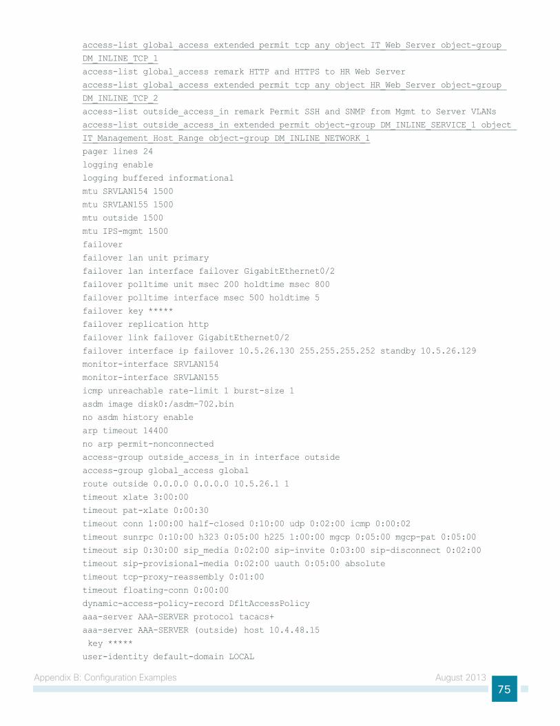
Appendix B: configuration examples August 201375
access-list global_access extended permit tcp any object IT_Web_Server object-group
DM_INLINE_TCP_1
access-list global_access remark HTTP and HTTPS to HR Web Server
access-list global_access extended permit tcp any object HR_Web_Server object-group
DM_INLINE_TCP_2
access-list outside_access_in remark Permit SSH and SNMP from Mgmt to Server VLANs
access-list outside_access_in extended permit object-group DM_INLINE_SERVICE_1 object
IT_Management_Host_Range object-group DM_INLINE_NETWORK_1
pager lines 24
logging enable
logging buffered informational
mtu SRVLAN154 1500
mtu SRVLAN155 1500
mtu outside 1500
mtu IPS-mgmt 1500
failover
failover lan unit primary
failover lan interface failover GigabitEthernet0/2
failover polltime unit msec 200 holdtime msec 800
failover polltime interface msec 500 holdtime 5
failover key *****
failover replication http
failover link failover GigabitEthernet0/2
failover interface ip failover 10.5.26.130 255.255.255.252 standby 10.5.26.129
monitor-interface SRVLAN154
monitor-interface SRVLAN155
icmp unreachable rate-limit 1 burst-size 1
asdm image disk0:/asdm-702.bin
no asdm history enable
arp timeout 14400
no arp permit-nonconnected
access-group outside_access_in in interface outside
access-group global_access global
route outside 0.0.0.0 0.0.0.0 10.5.26.1 1
timeout xlate 3:00:00
timeout pat-xlate 0:00:30
timeout conn 1:00:00 half-closed 0:10:00 udp 0:02:00 icmp 0:00:02
timeout sunrpc 0:10:00 h323 0:05:00 h225 1:00:00 mgcp 0:05:00 mgcp-pat 0:05:00
timeout sip 0:30:00 sip_media 0:02:00 sip-invite 0:03:00 sip-disconnect 0:02:00
timeout sip-provisional-media 0:02:00 uauth 0:05:00 absolute
timeout tcp-proxy-reassembly 0:01:00
timeout floating-conn 0:00:00
dynamic-access-policy-record DfltAccessPolicy
aaa-server AAA-SERVER protocol tacacs+
aaa-server AAA-SERVER (outside) host 10.4.48.15
key *****
user-identity default-domain LOCAL
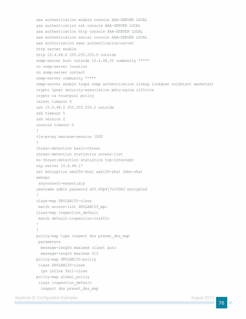
Appendix B: configuration examples August 201376
aaa authentication enable console AAA-SERVER LOCAL
aaa authentication ssh console AAA-SERVER LOCAL
aaa authentication http console AAA-SERVER LOCAL
aaa authentication serial console AAA-SERVER LOCAL
aaa authorization exec authentication-server
http server enable
http 10.4.48.0 255.255.255.0 outside
snmp-server host outside 10.4.48.35 community *****
no snmp-server location
no snmp-server contact
snmp-server community *****
snmp-server enable traps snmp authentication linkup linkdown coldstart warmstart
crypto ipsec security-association pmtu-aging infinite
crypto ca trustpool policy
telnet timeout 5
ssh 10.4.48.0 255.255.255.0 outside
ssh timeout 5
ssh version 2
console timeout 0
!
tls-proxy maximum-session 1000
!
threat-detection basic-threat
threat-detection statistics access-list
no threat-detection statistics tcp-intercept
ntp server 10.4.48.17
ssl encryption aes256-sha1 aes128-sha1 3des-sha1
webvpn
anyconnect-essentials
username admin password w2Y.6Op4j7clVDk2 encrypted
!
class-map SRVLAN155-class
match access-list SRVLAN155_mpc
class-map inspection_default
match default-inspection-traffic
!
!
policy-map type inspect dns preset_dns_map
parameters
message-length maximum client auto
message-length maximum 512
policy-map SRVLAN155-policy
class SRVLAN155-class
ips inline fail-close
policy-map global_policy
class inspection_default
inspect dns preset_dns_map
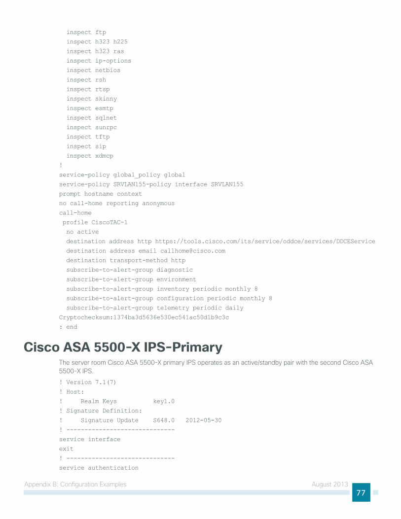
Appendix B: configuration examples August 201377
inspect ftp
inspect h323 h225
inspect h323 ras
inspect ip-options
inspect netbios
inspect rsh
inspect rtsp
inspect skinny
inspect esmtp
inspect sqlnet
inspect sunrpc
inspect tftp
inspect sip
inspect xdmcp
!
service-policy global_policy global
service-policy SRVLAN155-policy interface SRVLAN155
prompt hostname context
no call-home reporting anonymous
call-home
profile CiscoTAC-1
no active
destination address http https://tools.cisco.com/its/service/oddce/services/DDCEService
destination address email [email protected]
destination transport-method http
subscribe-to-alert-group diagnostic
subscribe-to-alert-group environment
subscribe-to-alert-group inventory periodic monthly 8
subscribe-to-alert-group configuration periodic monthly 8
subscribe-to-alert-group telemetry periodic daily
Cryptochecksum:1374ba3d5636e530ec541ac50d1b9c3c
: end
Cisco ASA 5500-X IPS-Primarythe server room cisco ASA 5500-X primary iPS operates as an active/standby pair with the second cisco ASA 5500-X iPS.
! Version 7.1(7)
! Host:
! Realm Keys key1.0
! Signature Definition:
! Signature Update S648.0 2012-05-30
! ------------------------------
service interface
exit
! ------------------------------
service authentication
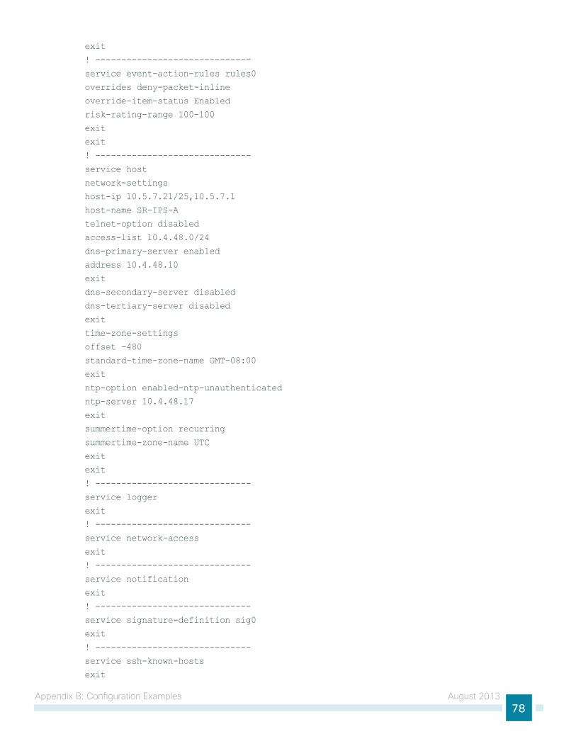
Appendix B: configuration examples August 201378
exit
! ------------------------------
service event-action-rules rules0
overrides deny-packet-inline
override-item-status Enabled
risk-rating-range 100-100
exit
exit
! ------------------------------
service host
network-settings
host-ip 10.5.7.21/25,10.5.7.1
host-name SR-IPS-A
telnet-option disabled
access-list 10.4.48.0/24
dns-primary-server enabled
address 10.4.48.10
exit
dns-secondary-server disabled
dns-tertiary-server disabled
exit
time-zone-settings
offset -480
standard-time-zone-name GMT-08:00
exit
ntp-option enabled-ntp-unauthenticated
ntp-server 10.4.48.17
exit
summertime-option recurring
summertime-zone-name UTC
exit
exit
! ------------------------------
service logger
exit
! ------------------------------
service network-access
exit
! ------------------------------
service notification
exit
! ------------------------------
service signature-definition sig0
exit
! ------------------------------
service ssh-known-hosts
exit
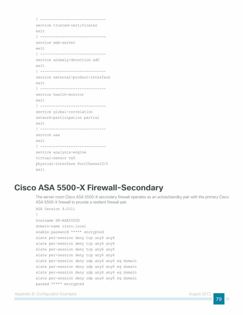
Appendix B: configuration examples August 201379
! ------------------------------
service trusted-certificates
exit
! ------------------------------
service web-server
exit
! ------------------------------
service anomaly-detection ad0
exit
! ------------------------------
service external-product-interface
exit
! ------------------------------
service health-monitor
exit
! ------------------------------
service global-correlation
network-participation partial
exit
! ------------------------------
service aaa
exit
! ------------------------------
service analysis-engine
virtual-sensor vs0
physical-interface PortChannel0/0
exit
Cisco ASA 5500-X Firewall-Secondarythe server room cisco ASA 5500-X secondary firewall operates as an active/standby pair with the primary cisco ASA 5500-X firewall to provide a resilient firewall pair.
ASA Version 9.0(1)
!
hostname SR-ASA5500X
domain-name cisco.local
enable password ***** encrypted
xlate per-session deny tcp any4 any4
xlate per-session deny tcp any4 any6
xlate per-session deny tcp any6 any4
xlate per-session deny tcp any6 any6
xlate per-session deny udp any4 any4 eq domain
xlate per-session deny udp any4 any6 eq domain
xlate per-session deny udp any6 any4 eq domain
xlate per-session deny udp any6 any6 eq domain
passwd ***** encrypted
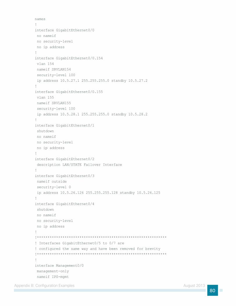
Appendix B: configuration examples August 201380
names
!
interface GigabitEthernet0/0
no nameif
no security-level
no ip address
!
interface GigabitEthernet0/0.154
vlan 154
nameif SRVLAN154
security-level 100
ip address 10.5.27.1 255.255.255.0 standby 10.5.27.2
!
interface GigabitEthernet0/0.155
vlan 155
nameif SRVLAN155
security-level 100
ip address 10.5.28.1 255.255.255.0 standby 10.5.28.2
!
interface GigabitEthernet0/1
shutdown
no nameif
no security-level
no ip address
!
interface GigabitEthernet0/2
description LAN/STATE Failover Interface
!
interface GigabitEthernet0/3
nameif outside
security-level 0
ip address 10.5.26.126 255.255.255.128 standby 10.5.26.125
!
interface GigabitEthernet0/4
shutdown
no nameif
no security-level
no ip address
!
!*************************************************************
! Interfaces GigabitEthernet0/5 to 0/7 are
! configured the same way and have been removed for brevity
!*************************************************************
!
interface Management0/0
management-only
nameif IPS-mgmt
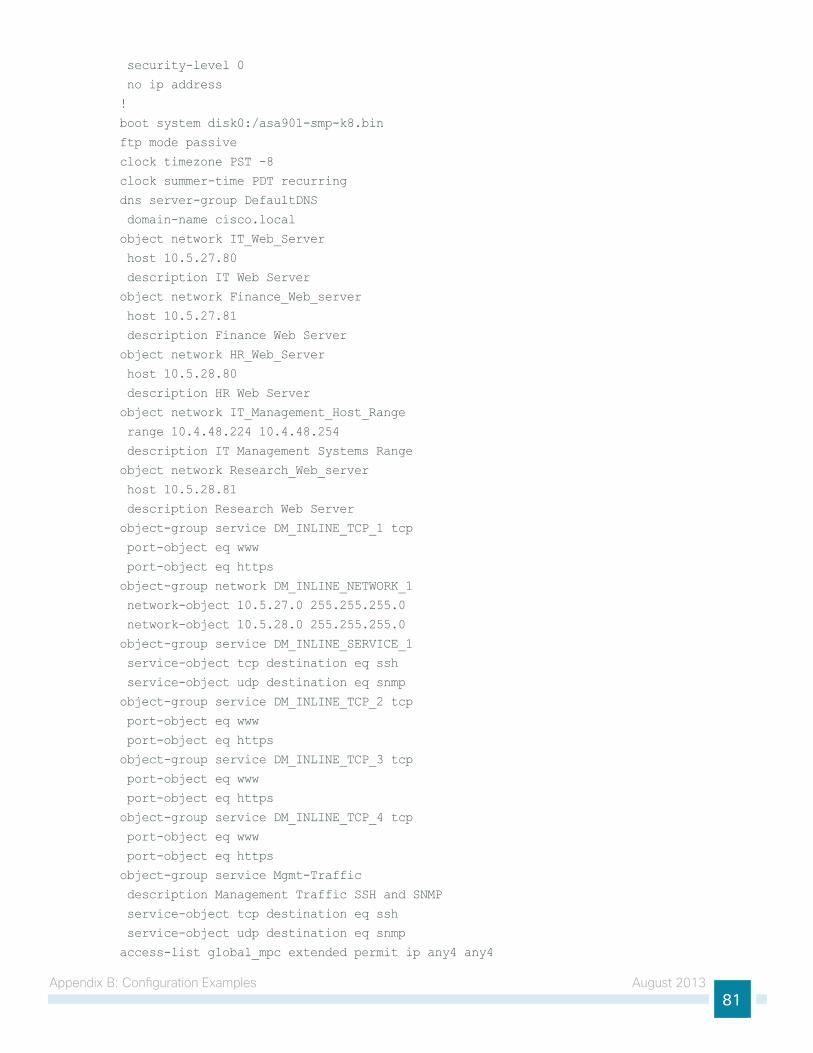
Appendix B: configuration examples August 201381
security-level 0
no ip address
!
boot system disk0:/asa901-smp-k8.bin
ftp mode passive
clock timezone PST -8
clock summer-time PDT recurring
dns server-group DefaultDNS
domain-name cisco.local
object network IT_Web_Server
host 10.5.27.80
description IT Web Server
object network Finance_Web_server
host 10.5.27.81
description Finance Web Server
object network HR_Web_Server
host 10.5.28.80
description HR Web Server
object network IT_Management_Host_Range
range 10.4.48.224 10.4.48.254
description IT Management Systems Range
object network Research_Web_server
host 10.5.28.81
description Research Web Server
object-group service DM_INLINE_TCP_1 tcp
port-object eq www
port-object eq https
object-group network DM_INLINE_NETWORK_1
network-object 10.5.27.0 255.255.255.0
network-object 10.5.28.0 255.255.255.0
object-group service DM_INLINE_SERVICE_1
service-object tcp destination eq ssh
service-object udp destination eq snmp
object-group service DM_INLINE_TCP_2 tcp
port-object eq www
port-object eq https
object-group service DM_INLINE_TCP_3 tcp
port-object eq www
port-object eq https
object-group service DM_INLINE_TCP_4 tcp
port-object eq www
port-object eq https
object-group service Mgmt-Traffic
description Management Traffic SSH and SNMP
service-object tcp destination eq ssh
service-object udp destination eq snmp
access-list global_mpc extended permit ip any4 any4
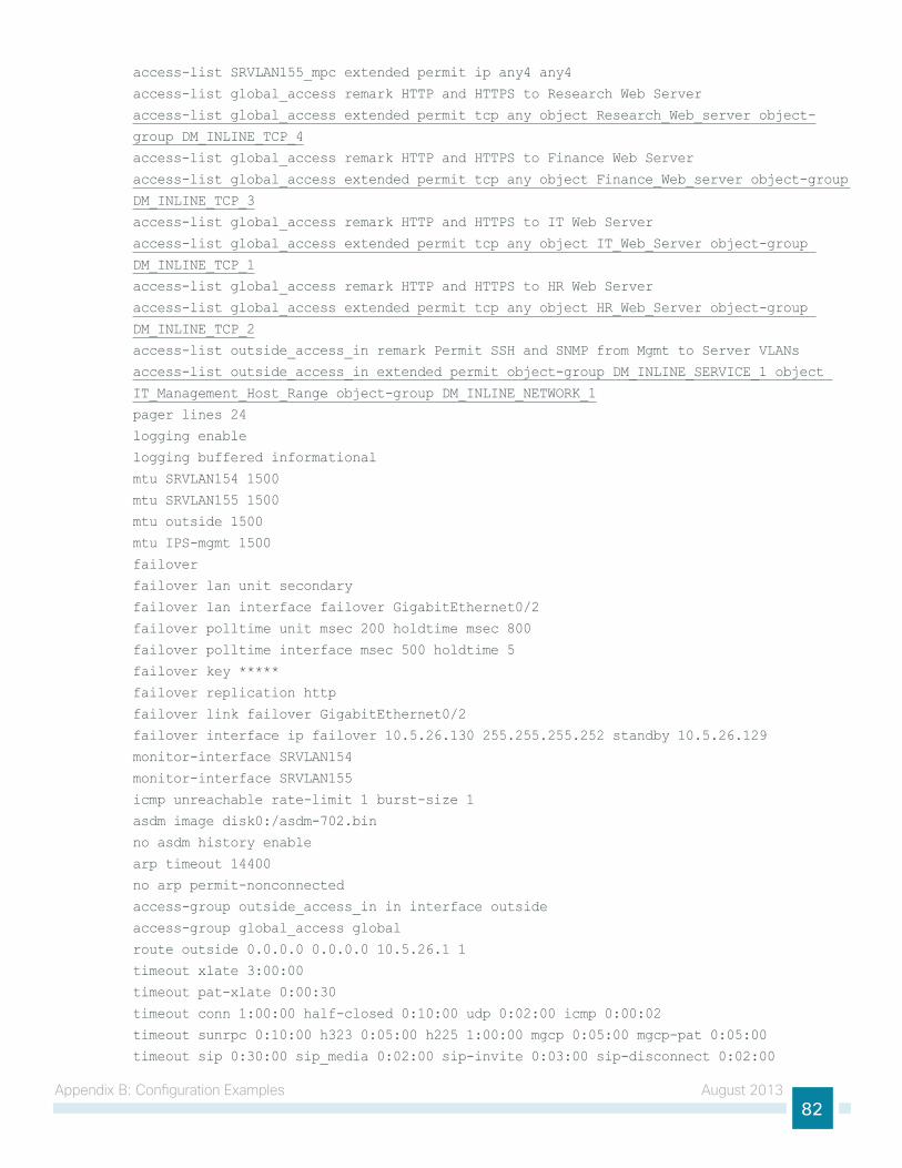
Appendix B: configuration examples August 201382
access-list SRVLAN155_mpc extended permit ip any4 any4
access-list global_access remark HTTP and HTTPS to Research Web Server
access-list global_access extended permit tcp any object Research_Web_server object-
group DM_INLINE_TCP_4
access-list global_access remark HTTP and HTTPS to Finance Web Server
access-list global_access extended permit tcp any object Finance_Web_server object-group
DM_INLINE_TCP_3
access-list global_access remark HTTP and HTTPS to IT Web Server
access-list global_access extended permit tcp any object IT_Web_Server object-group
DM_INLINE_TCP_1
access-list global_access remark HTTP and HTTPS to HR Web Server
access-list global_access extended permit tcp any object HR_Web_Server object-group
DM_INLINE_TCP_2
access-list outside_access_in remark Permit SSH and SNMP from Mgmt to Server VLANs
access-list outside_access_in extended permit object-group DM_INLINE_SERVICE_1 object
IT_Management_Host_Range object-group DM_INLINE_NETWORK_1
pager lines 24
logging enable
logging buffered informational
mtu SRVLAN154 1500
mtu SRVLAN155 1500
mtu outside 1500
mtu IPS-mgmt 1500
failover
failover lan unit secondary
failover lan interface failover GigabitEthernet0/2
failover polltime unit msec 200 holdtime msec 800
failover polltime interface msec 500 holdtime 5
failover key *****
failover replication http
failover link failover GigabitEthernet0/2
failover interface ip failover 10.5.26.130 255.255.255.252 standby 10.5.26.129
monitor-interface SRVLAN154
monitor-interface SRVLAN155
icmp unreachable rate-limit 1 burst-size 1
asdm image disk0:/asdm-702.bin
no asdm history enable
arp timeout 14400
no arp permit-nonconnected
access-group outside_access_in in interface outside
access-group global_access global
route outside 0.0.0.0 0.0.0.0 10.5.26.1 1
timeout xlate 3:00:00
timeout pat-xlate 0:00:30
timeout conn 1:00:00 half-closed 0:10:00 udp 0:02:00 icmp 0:00:02
timeout sunrpc 0:10:00 h323 0:05:00 h225 1:00:00 mgcp 0:05:00 mgcp-pat 0:05:00
timeout sip 0:30:00 sip_media 0:02:00 sip-invite 0:03:00 sip-disconnect 0:02:00
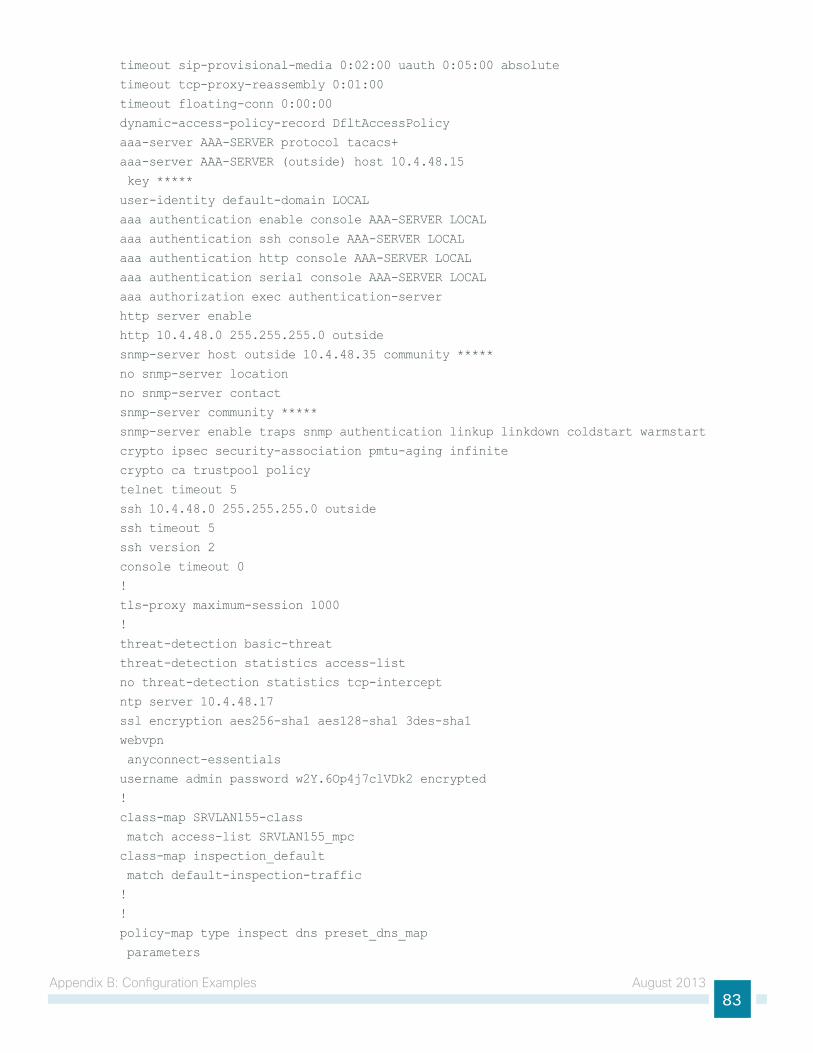
Appendix B: configuration examples August 201383
timeout sip-provisional-media 0:02:00 uauth 0:05:00 absolute
timeout tcp-proxy-reassembly 0:01:00
timeout floating-conn 0:00:00
dynamic-access-policy-record DfltAccessPolicy
aaa-server AAA-SERVER protocol tacacs+
aaa-server AAA-SERVER (outside) host 10.4.48.15
key *****
user-identity default-domain LOCAL
aaa authentication enable console AAA-SERVER LOCAL
aaa authentication ssh console AAA-SERVER LOCAL
aaa authentication http console AAA-SERVER LOCAL
aaa authentication serial console AAA-SERVER LOCAL
aaa authorization exec authentication-server
http server enable
http 10.4.48.0 255.255.255.0 outside
snmp-server host outside 10.4.48.35 community *****
no snmp-server location
no snmp-server contact
snmp-server community *****
snmp-server enable traps snmp authentication linkup linkdown coldstart warmstart
crypto ipsec security-association pmtu-aging infinite
crypto ca trustpool policy
telnet timeout 5
ssh 10.4.48.0 255.255.255.0 outside
ssh timeout 5
ssh version 2
console timeout 0
!
tls-proxy maximum-session 1000
!
threat-detection basic-threat
threat-detection statistics access-list
no threat-detection statistics tcp-intercept
ntp server 10.4.48.17
ssl encryption aes256-sha1 aes128-sha1 3des-sha1
webvpn
anyconnect-essentials
username admin password w2Y.6Op4j7clVDk2 encrypted
!
class-map SRVLAN155-class
match access-list SRVLAN155_mpc
class-map inspection_default
match default-inspection-traffic
!
!
policy-map type inspect dns preset_dns_map
parameters
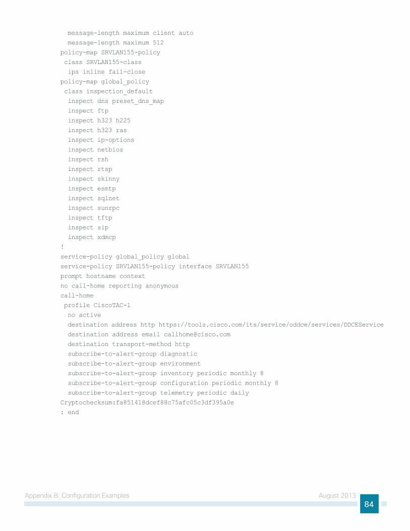
Appendix B: configuration examples August 201384
message-length maximum client auto
message-length maximum 512
policy-map SRVLAN155-policy
class SRVLAN155-class
ips inline fail-close
policy-map global_policy
class inspection_default
inspect dns preset_dns_map
inspect ftp
inspect h323 h225
inspect h323 ras
inspect ip-options
inspect netbios
inspect rsh
inspect rtsp
inspect skinny
inspect esmtp
inspect sqlnet
inspect sunrpc
inspect tftp
inspect sip
inspect xdmcp
!
service-policy global_policy global
service-policy SRVLAN155-policy interface SRVLAN155
prompt hostname context
no call-home reporting anonymous
call-home
profile CiscoTAC-1
no active
destination address http https://tools.cisco.com/its/service/oddce/services/DDCEService
destination address email [email protected]
destination transport-method http
subscribe-to-alert-group diagnostic
subscribe-to-alert-group environment
subscribe-to-alert-group inventory periodic monthly 8
subscribe-to-alert-group configuration periodic monthly 8
subscribe-to-alert-group telemetry periodic daily
Cryptochecksum:fa851418dcef88c75afc05c3df395a0e
: end
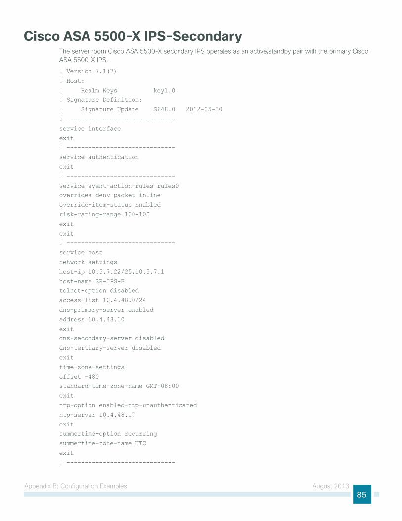
Appendix B: configuration examples August 201385
Cisco ASA 5500-X IPS-Secondarythe server room cisco ASA 5500-X secondary iPS operates as an active/standby pair with the primary cisco ASA 5500-X iPS.
! Version 7.1(7)
! Host:
! Realm Keys key1.0
! Signature Definition:
! Signature Update S648.0 2012-05-30
! ------------------------------
service interface
exit
! ------------------------------
service authentication
exit
! ------------------------------
service event-action-rules rules0
overrides deny-packet-inline
override-item-status Enabled
risk-rating-range 100-100
exit
exit
! ------------------------------
service host
network-settings
host-ip 10.5.7.22/25,10.5.7.1
host-name SR-IPS-B
telnet-option disabled
access-list 10.4.48.0/24
dns-primary-server enabled
address 10.4.48.10
exit
dns-secondary-server disabled
dns-tertiary-server disabled
exit
time-zone-settings
offset -480
standard-time-zone-name GMT-08:00
exit
ntp-option enabled-ntp-unauthenticated
ntp-server 10.4.48.17
exit
summertime-option recurring
summertime-zone-name UTC
exit
! ------------------------------
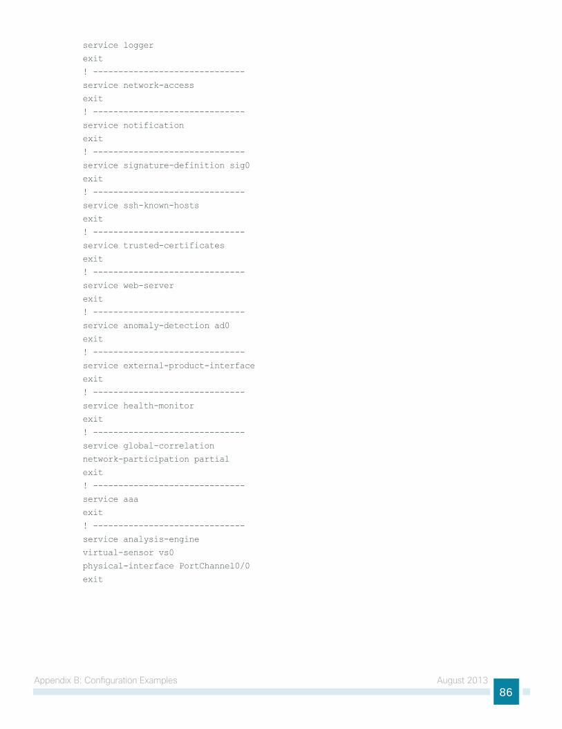
Appendix B: configuration examples August 201386
service logger
exit
! ------------------------------
service network-access
exit
! ------------------------------
service notification
exit
! ------------------------------
service signature-definition sig0
exit
! ------------------------------
service ssh-known-hosts
exit
! ------------------------------
service trusted-certificates
exit
! ------------------------------
service web-server
exit
! ------------------------------
service anomaly-detection ad0
exit
! ------------------------------
service external-product-interface
exit
! ------------------------------
service health-monitor
exit
! ------------------------------
service global-correlation
network-participation partial
exit
! ------------------------------
service aaa
exit
! ------------------------------
service analysis-engine
virtual-sensor vs0
physical-interface PortChannel0/0
exit
Americas HeadquartersCisco Systems, Inc.San Jose, CA
Asia Pacific HeadquartersCisco Systems (USA) Pte. Ltd.Singapore
Europe HeadquartersCisco Systems International BV Amsterdam,The Netherlands
Cisco has more than 200 offices worldwide. Addresses, phone numbers, and fax numbers are listed on the Cisco Website at www.cisco.com/go/offices.
ALL DESIGNS, SPECIFICATIONS, STATEMENTS, INFORMATION, AND RECOMMENDATIONS (COLLECTIVELY, “DESIGNS”) IN THIS MANUAL ARE PRESENTED “AS IS,” WITH ALL FAULTS. CISCO AND ITS SUPPLIERS DISCLAIM ALL WARRANTIES, INCLUDING, WITHOUT LIMITATION, THE WARRANTY OF MERCHANTABILITY, FITNESS FOR A PARTICULAR PURPOSE AND NONINFRINGEMENT OR ARISING FROM A COURSE OF DEALING, USAGE, OR TRADE PRACTICE. IN NO EVENT SHALL CISCO OR ITS SUPPLIERS BE LIABLE FOR ANY INDIRECT, SPECIAL, CONSEQUENTIAL, OR INCIDENTAL DAMAGES, INCLUDING, WITHOUT LIMITATION, LOST PROFITS OR LOSS OR DAMAGE TO DATA ARISING OUT OF THE USE OR INABILITY TO USE THE DESIGNS, EVEN IF CISCO OR ITS SUPPLIERS HAVE BEEN ADVISED OF THE POSSIBILITY OF SUCH DAMAGES. THE DESIGNS ARE SUBJECT TO CHANGE WITHOUT NOTICE. USERS ARE SOLELY RESPONSIBLE FOR THEIR APPLICATION OF THE DESIGNS. THE DESIGNS DO NOT CONSTITUTE THE TECHNICAL OR OTHER PROFESSIONAL ADVICE OF CISCO, ITS SUPPLIERS OR PARTNERS. USERS SHOULD CONSULT THEIR OWN TECHNICAL ADVISORS BEFORE IMPLEMENTING THE DESIGNS. RESULTS MAY VARY DEPENDING ON FACTORS NOT TESTED BY CISCO.
Any Internet Protocol (IP) addresses used in this document are not intended to be actual addresses. Any examples, command display output, and figures included in the document are shown for illustrative purposes only. Any use of actual IP addresses in illustrative content is unintentional and coincidental.
© 2013 Cisco Systems, Inc. All rights reserved.
Cisco and the Cisco logo are trademarks or registered trademarks of Cisco and/or its affiliates in the U.S. and other countries. To view a list of Cisco trademarks, go to this URL: www.cisco.com/go/trademarks. Third-party trademarks mentioned are the property of their respective owners. The use of the word partner does not imply a partnership relationship between Cisco and any other company. (1110R)
Please use the feedback form to send comments and suggestions about this guide.
Feedback
B-0000535-1 08/13