CVA 640x 680x TI - JustAnswer
104
TECHNICAL INFORMATION CVA 640x and CVA 680x Coffee Systems © 2015 Miele USA
Transcript of CVA 640x 680x TI - JustAnswer

TECHNICAL INFORMATION CVA 640x and CVA 680x Coffee Systems
© 2015 Miele USA

Technical Information
2
CVA 640x/680x
Table of Contents A Warning and Safety Instructions ....................................................................... 7 1 General .................................................................................................................. 7 2 Risk of Burning or Scalding ................................................................................... 7 3 Touch Current Measurement ................................................................................ 8
B Modification History ............................................................................................ 8
C Technical Data ..................................................................................................... 9
D Component Layouts .......................................................................................... 14 1 Optical Interface .................................................................................................. 14 2 Electrical Components ........................................................................................ 15
001 General ............................................................................................................... 21 2 Function ............................................................................................................... 21
2.1 Optical Interface ........................................................................................... 21 2.2 Water Paths .................................................................................................. 21
2.2.1 Overview .................................................................................................. 21 2.2.2 Water Path – Coffee ................................................................................ 22 2.2.3 Water Path - Decompression - Coffee .................................................... 23 2.2.4 Water Path – Hot Water .......................................................................... 23 2.2.5 Water Path – Decompression - Hot Water .............................................. 24 2.2.6 Water Path – Milk Froth ........................................................................... 24 2.2.7 Water Path – Hot Milk .............................................................................. 25 2.2.8 Water Path – Cold Rinse ......................................................................... 25 2.2.9 Water Path – Hot Rinse ........................................................................... 26
2.3 Brew Unit Control ......................................................................................... 26 2.3.1 Switch Positions ...................................................................................... 26 2.3.2 Electronic Grind Amount Compensation ................................................. 27 2.3.3 Brew Unit Drive, Home Position .............................................................. 28 2.3.4 Brew Unit Drive, Compressing Position (Brew Position) ......................... 29 2.3.5 Brew Unit Drive, Drain Position ............................................................... 30
2.4 Waste-Container Monitoring ......................................................................... 31 2.5 Machine Response after a Power Failure ..................................................... 31 2.6 Safety Concept for Water Intake (CVA 6x05 Only) ....................................... 31
3 Fault Repair ......................................................................................................... 32 3.1 F001 -- Coffee/Hot Water NTC (R30-14) Short-Circuited ............................. 32 3.2 F002 -- Coffee/Hot Water NTC (R30-14) Open-Circuited ............................. 32 3.3 F003 -- Steam NTC (R30-13) Short-Circuited .............................................. 33 3.4 F004 -- Steam NTC (R30-13) Open-Circuited .............................................. 33 3.5 F010 -- No Water Intake ............................................................................... 34 3.6 F017 -- Insufficient Water Intake ................................................................... 35 3.7 F028 -- Too Much Ground Coffee in Brew Unit ............................................ 36 3.8 F040 - Power Electronic EPL (N1-1) Fault.................................................... 36 3.9 F041 -- EEPROM Faulty/Data Fault ............................................................. 37 3.10 F042 -- Line Frequency Not Registered ....................................................... 37 3.11 F073 -- Brew Unit Fault................................................................................. 37 3.12 F074 -- Ceramic Valve (1M29) Fault ............................................................ 38 3.13 F076 -- Brew Unit Compression Fault .......................................................... 38 3.14 F077 -- Ceramic Valve (1M29) Initialization Fault ......................................... 38 3.15 F080 -- Coffee/Hot-Water Heater (R1-2) Not Heating .................................. 39 3.16 F081 -- Steam Heater (R1-1) Not Heating .................................................... 39

Technical Information
3
CVA 640x/680x
3.17 F082 -- Coffee/Hot-Water Heater (R1-2) Overheating .................................. 40 3.18 F083 -- Steam Heater (R1-1) Overheating ................................................... 41 3.19 F094 -- Water Intake Fault (CVA 6x05 Only) ................................................ 41 3.20 F225 -- Ceramic Valve (2M29) Fault ............................................................ 42 3.21 F226 -- Ceramic Valve (2M29) Initializing Fault ............................................ 43 3.22 F227 -- Cup-Edge Sensor (1B10) Short-Circuited ........................................ 43 3.23 F228 -- Cup-Edge Sensor (1B10) Open-Circuited ........................................ 43 3.24 F229 -- Cup-Edge Sensor (2B10) Short-Circuited ........................................ 43 3.25 F230 -- Cup-Edge Sensor (2B10) Open-Circuited ........................................ 44 3.26 F233 -- Cup Protection Switch (S86) Not Active ........................................... 44 3.27 F234 -- Cup Protection Switch (S86) Was Activated .................................... 45 3.28 F235 -- Display Electronic EPB (N1-2) Communication Fault ....................... 46 3.29 F236 -- Auxiliary Electronic EPZ (N1-25) Communication Fault ................... 46 3.30 "X Servings until Descaling" Shown in Display ............................................. 46 3.31 "Empty Drip Tray" Message, Even Though Drip Tray Is Not Full .................. 46 3.32 "Replace Drip Tray" Message, Even Though Drip Tray Is Inserted .............. 46 3.33 “Empty Waste Container” Message, But Waste Container Is Not Full .......... 47 3.34 ”Fill Milk Container” Message Not Displayed ................................................ 47 3.35 Built-In Depths Different ............................................................................... 47 3.36 Door Jams when Opening ............................................................................ 48 3.37 Coffee or Espresso Too Cold ....................................................................... 48 3.38 Milk Froth Unsatisfactory or Sputtering ......................................................... 48 3.39 No or Very Little Coffee Flowing from Spout ................................................. 49 3.40 Coffee Tastes Too Bitter ............................................................................... 49 3.41 Coffee Grounds Next to the Brew Unit ......................................................... 49 3.42 Coffee/Hot Water Pump or Steam Pump Inoperative ................................... 50 3.43 Diagnostic Support Cannot Establish a Connection ..................................... 50 3.44 Pump Running Constantly ............................................................................ 51 3.45 Milk Froth Stream is Inconsistent .................................................................. 51 3.46 Empty Milk Container Not Detected .............................................................. 51
4 Service ................................................................................................................ 52 4.1 Drink Settings (Customer Programming) ...................................................... 52
4.1.1 CVA 640x ................................................................................................ 52 4.1.2 CVA 680x ................................................................................................ 53
4.2 Machine Settings (Customer Programming) ................................................. 55 4.2.1 CVA 640x ................................................................................................ 55 4.2.2 CVA 680x ................................................................................................ 59
4.3 Service Programming Mode ......................................................................... 63 4.3.1 CVA 640x ................................................................................................ 63 4.3.2 CVA 680x ................................................................................................ 64
4.4 Service Mode ................................................................................................ 65 4.4.1 CVA 640x ................................................................................................ 65 4.4.2 CVA 680x ................................................................................................ 70
4.5 Removing the Appliance from a Cabinet ...................................................... 74 4.6 Top Rear Panel Removal ............................................................................. 74 4.7 Bottom Rear Panel Removal ........................................................................ 75 4.8 Preparing Machine for Servicing ................................................................... 76 4.9 Heater (Steam R1-1 or Coffee/Hot-Water R1-2) Removal ........................... 77 4.10 Heater NTC (Steam R30-13 or Coffee/Hot-Water R30-14) Removal ........... 78 4.11 Heater Temperature Limiter (Steam F1-5 or Coffee/Hot-Water F1-8) Removal
78 4.12 Heater Fuse (Steam F8-1 or Coffee/Hot-Water F8-2) Removal ................... 78 4.13 Pump (Steam M7-1 or Coffee/Hot-Water M7-2) Removal ............................ 78

Technical Information
4
CVA 640x/680x
4.14 Pump Temperature Limiter (Steam F3-1 or Coffee/Hot-Water F3-2) Removal79 4.15 Ceramic Valve 1M29 Removal ..................................................................... 79 4.16 Ceramic Valve 2M29 Removal ..................................................................... 80 4.17 Inlet Valve Removal (CVA 6x05 Only) .......................................................... 80 4.18 EPL Power Electronic (N1-1) Removal ......................................................... 80 4.19 Coffee Chute Monitor Switch (S87-5) Removal ............................................ 81 4.20 Beans Container Sensor (1B3-14, 2B3-14) Removal ................................... 83 4.21 Grinder (M25) Removal ................................................................................ 84 4.22 Grinder Temperature Limiter (F3-3) Removal ............................................... 85 4.23 Brew Unit Drive (M26) Removal ................................................................... 85 4.24 Brew Unit Present Switch (S87-2) Removal ................................................. 87 4.25 Brew Unit Position Switch (S60-1, S60-2) Removal ..................................... 87 4.26 Grind Amount Step Contact Switch (S51-4) Removal .................................. 87 4.27 Door Contact Switch (S24) Removal ............................................................ 87 4.28 Removing the Drip Tray Contact Springs from Inside the Appliance ............ 88 4.29 Water Tank Level Switch (S12-1 or S12-3) Removal ................................... 88 4.30 Flow Meter (B3-4) Removal .......................................................................... 88 4.31 Waste Container Present Switch (S87-4) Removal ...................................... 90 4.32 RemoteVision Module Removal (CVA 680x Only) ........................................ 90 4.33 Inner Door Cover Removal ........................................................................... 90 4.34 Dispenser Adjustment Motor (M19) Removal (CVA 680x Only) ................... 92 4.35 Spout Monitor Switch (S87-6) Removal ........................................................ 93
4.35.1 CVA 640x ................................................................................................ 93 4.35.2 CVA 680x ................................................................................................ 93
4.36 Dispensing-Area Light (H3) Removal ........................................................... 95 4.36.1 CVA 640x ................................................................................................ 95 4.36.2 CVA 680x ................................................................................................ 95
4.37 Cup Protection Switch (S86) Removal (CVA 680x Only) .............................. 97 4.38 Cup-Edge Sensor (1B10, 2B10) Removal (CVA 680x Only) ........................ 97 4.39 Milk Container Level Sensor (S12-4) Removal ............................................. 98 4.40 Milk Valve (M24) Removal .......................................................................... 100 4.41 Air Valve (M28) Removal ............................................................................ 101 4.42 Auxiliary Electronic EPZ (N1-25) Removal ................................................. 101 4.43 Control Panel and Display Electronic EPB (N1-2) Removal ....................... 102
List of Figures
Figure D-1: Optical Interface for Diagnostic Support and Program Updating ................. 14 Figure D-2: CVA 6401 ..................................................................................................... 15 Figure D-3: CVA 6405 ..................................................................................................... 16 Figure D-4: CVA 6800 ..................................................................................................... 17 Figure D-5: CVA 6805 ..................................................................................................... 19 Figure 001-1: CVA Water Path - Overview ..................................................................... 21 Figure 001-2: Coffee Water Path .................................................................................... 22 Figure 001-3: Coffee Water Path, Decompression ......................................................... 23 Figure 001-4: Hot-Water Path ......................................................................................... 23 Figure 001-5: Hot-Water Path, Decompression .............................................................. 24 Figure 001-6: Milk Froth Path .......................................................................................... 24 Figure 001-7: Hot-Milk Path ............................................................................................ 25 Figure 001-8: Cold-Rinse Path ........................................................................................ 25

Technical Information
5
CVA 640x/680x
Figure 001-9: Hot-Rinse Path ......................................................................................... 26 Figure 001-10: Brew Unit Microswitches ......................................................................... 27 Figure 001-11: Brew Unit Switching Cam, Ground Quantity Compensation Microswitch ..................................................................................................................... 27 Figure 001-12: Measurable Volume Areas 1, 2 and 3 .................................................... 28 Figure 001-13: Selectable Volume Areas 1, 2 and 3 ...................................................... 28 Figure 001-14: Home Position, Rear View ...................................................................... 29 Figure 001-15: Home Position, Front View ..................................................................... 29 Figure 001-16: Compressing Position, Rear View .......................................................... 30 Figure 001-17: Compressing Position, Front View .......................................................... 30 Figure 001-18: Drain Position, Rear View ....................................................................... 31 Figure 001-19: Drain Position, Front View ...................................................................... 31 Figure 001-20: Pressure Pump ....................................................................................... 34 Figure 001-21: Brew Unit Position Switches ................................................................... 37 Figure 001-22: Coffee Hose Placement .......................................................................... 45 Figure 001-23: Coupling Piece on Inside of Door ........................................................... 48 Figure 001-24: Ground Quantity Step Contact Switch .................................................... 50 Figure 001-25: Three-Part Connector on Flow Meter ..................................................... 51 Figure 001-26: Removing the Appliance from a Cabinet ................................................ 74 Figure 001-27: Top Rear Panel Removal ....................................................................... 75 Figure 001-28: Bottom Rear Panel and Service Door Screws ........................................ 76 Figure 001-29: Service Door, Open ................................................................................ 76 Figure 001-30: Service Door Open, Showing Heaters .................................................... 77 Figure 001-31: Heater Water Line Connections .............................................................. 77 Figure 001-32: Heater Assembly .................................................................................... 78 Figure 001-33: Pump Assembly ...................................................................................... 79 Figure 001-34: EPL Power Electronic (N1-1) Removal ................................................... 81 Figure 001-35: Adjustment Lever Handle ....................................................................... 81 Figure 001-36: Bean Container Guide Retaining Screws ............................................... 82 Figure 001-37: Grinder Screws ....................................................................................... 82 Figure 001-38: Chute Monitor Switch and Screws .......................................................... 83 Figure 001-39: Beans Container Sensor Removal ......................................................... 84 Figure 001-40: Grinder and Temperature Limiter ........................................................... 85 Figure 001-41: Brew Unit Drive ....................................................................................... 86 Figure 001-42: Brew Unit Removal ................................................................................. 86 Figure 001-43: Brew Unit Drive Retaining Screws .......................................................... 87 Figure 001-44: Flow Meter .............................................................................................. 89 Figure 001-45: Flow Meter (1) and Plastic Support (2) ................................................... 89 Figure 001-46: Access Hole for Waste Container Monitor Switch .................................. 90 Figure 001-47: Service Cover ......................................................................................... 91 Figure 001-48: Hose on Inner Door Cover ...................................................................... 91 Figure 001-49: Inner Door Cover Screws ....................................................................... 92 Figure 001-50: Dispenser Adjustment Motor M19 .......................................................... 93 Figure 001-51: Spout Holder and Pin Bracket, CVA 680x .............................................. 94 Figure 001-52: Spout Monitor Switch .............................................................................. 94 Figure 001-53: Hose Bracket and Lighting Assembly ..................................................... 96 Figure 001-54: Lighting Assembly Mounting Bracket ...................................................... 96 Figure 001-55: Cup Protection Switch ............................................................................ 97 Figure 001-56: Cup-Edge Sensors ................................................................................. 98 Figure 001-57: Auxiliary Electronic Cover ....................................................................... 99

Technical Information
6
CVA 640x/680x
Figure 001-58: Sensor Blades ...................................................................................... 100 Figure 001-59: Milk Valve, Air Valve, Hose Bracket and Auxiliary Electronic Cover .... 101 Figure 001-60: Milk Container Receptacle Screws ....................................................... 102 Figure 001-61: Control Panel Screws ........................................................................... 102 Figure 001-62: EPB/EPZ Electronic with Housing (CVA 680x) ..................................... 103 Figure 001-63: Touchscreen ZIF Plug .......................................................................... 103 Figure 001-64: Display Electronic Removal, CVA 680x ................................................ 104
List of Tables Table C-1: CVA 640x Technical Data ............................................................................. 11 Table C-2: CVA 680x Technical Data ............................................................................. 13 Table C-3: Drink Temperatures ....................................................................................... 13 Table C-4: Quantities until Obligatory Descaling ............................................................ 13 Table C-5: Brew Unit Drive Specifications ...................................................................... 13 Table C-6: Coffee/Hot-Water Heater Data ...................................................................... 13 Table C-7: Steam Heater Data ........................................................................................ 14 Table C-8: Coffee/Hot-Water Pump Data ....................................................................... 14 Table C-9: Steam Pump Data ......................................................................................... 14 Table C-10: Flow Meter Data .......................................................................................... 14 Table 001-1: Switch Cam Settings .................................................................................. 28 Table 001-2: Drink Settings (Customer Programming), CVA 640x ................................. 53 Table 001-3: Drink Settings (Customer Programming), CVA 680x ................................. 54 Table 001-4: Machine Settings (Customer Programming), CVA 640x ............................ 58 Table 001-5: Machine Settings (Customer Programming), CVA 680x ............................ 62 Table 001-6: Service Programming Settings, CVA 640x ................................................ 64 Table 001-7: Service Programming Settings, CVA 680x ................................................ 65 Table 001-8: Service Mode, CVA 640x ........................................................................... 69 Table 001-9: S12-1/S12-3 ............................................................................................... 69 Table 001-10: S60-1/S60-2 ............................................................................................. 69 Table 001-11: Service Mode, CVA 680x ......................................................................... 73

Technical Information
7
CVA 640x/680x
A Warning and Safety Instructions
1 General Any repairs or maintenance performed by unqualified personnel could be dangerous. All applicable laws, codes, regulations, and accident prevention guidelines must be observed when serving, modifying, testing or maintaining appliances. All repairs should be performed by a trained technician in strict accordance with local, state and national codes.
Before any service work is started, the machine must be safely disconnected from its power source. Even with the machine switched off, voltage may exist on some components.
After work has been completed, as a matter of standard practice, a visual as well as an operational check should be performed.
Note: Prior to starting service or repair work, remove all containers and the drip tray with the spill guard grid from the appliance.
2 Risk of Burning or Scalding Some components may be very hot, such as heaters. Also, some components may contain pressurized steam. Use caution when working on these parts.
To protect from burns:
1. Allow the CVA to cool down for approximately one hour before starting service or
repair work, so that the heaters can cool. 2. In service mode, pump cool water through the heater for a few minutes to shorten
the cooling time. Use the component test for each pump. See Section 001-4.4

Technical Information
8
CVA 640x/680x
3 Touch Current Measurement Touch current measurement should be carried out on all accessible conductive parts that are not connected to ground.
Warning! Touch current measurement may only be performed after the ground connection of the appliance under test has been checked and found to be satisfactory! A defective appliance, as well as accessible conductive parts that are not connected to ground, may carry dangerous voltages!
B Modification History
When? Who? What?
1/15/2015 Jessica Naples Minor changes throughout
12/17/2014 Jessica Naples Minor changes throughout
11/25/2014 Jessica Naples Minor changes throughout
7/18/2014 Jessica Naples CVA 680x info added
2/24/2014 Jessica Naples Conversion for Website
1/15/2014 Sabine Hötte Revision
10/16/2013 Sabine Hötte Revision
7/17/2013 Sabine Hötte Initial compilation

Technical Information
9
CVA 640x/680x
C Technical Data
Figure C-1: CVA 640x
Model CVA 6401 CVA 6405Type Built-in coffee machine with bean system Design PureLine Yes Yes ContourLine Yes Yes Display DirectSensor Beverage specialities Espresso Yes Yes Coffee Yes Yes Large coffee Yes Yes Cappuccino Yes Yes Latte macchiato Yes Yes Caffè latte Yes Yes Hot water Yes Yes Hot milk Yes Yes Milk froth Yes Yes Convenience features OneTouch Yes Yes OneTouch for Two preparation Yes Yes Aroma-friendly conical grinder Yes Yes Second coffee type in powder form possible
Yes Yes
Programmable user profiles 10 10 Selectable grinding grade Yes Yes Programmable ground quantity Yes Yes Programmable water quantity Yes Yes Programmable water temperature Yes Yes

Technical Information
10
CVA 640x/680x
Model CVA 6401 CVA 6405Convenience features Programmable pre-brewing Yes Yes Programmable milk and milk froth amount
Yes Yes
Coffee pot function Yes Yes User convenience Individual language selection Yes Yes Time of day display Yes Yes Date display Yes Yes CupSensor No No Infinitely variable height-adjustable serving spout
8.5 - 16.5 cm 8.5 - 16.5 cm
ComfortDoor Yes Yes Hidden door handle Yes Yes BrilliantLight Yes Yes Removable coffee bean container Yes Yes Removable Nespresso capsule magazine
No No
Capacity Water tank 2.3 liters 2.3 liters Beans container 500 grams 500 grams Waste container 15 pucks 15 pucks Programmable on and off times Yes Yes Programmable standby time Yes Yes Time buffer 200 hours 200 hours Optional connection for warming drawer
No No
Plumbed water connection No Yes Door Door hinge Left Left Cleaning and care Convenient cleaning program Yes Yes ComfortClean Yes Yes Automatic flushing of milk pipework from water container
Yes Yes
Removable milk pipework Yes Yes Removable brew unit Yes Yes Efficiency and sustainability Energy-saving Eco mode Yes Yes Appliance networking RemoteVision-ready No No Safety System lock Yes Yes Technical data Appliance dimensions Height 452mm 452mm Width 595mm 595mm Depth 480mm 480mm Depth with door open 1060mm 1060mm Niche dimensions Height 448 - 452 mm 448 - 452 mm Width 560 - 568 mm 560 - 568 mm Depth 550mm 550mm Rated load 2.8kW 2.8kW

Technical Information
11
CVA 640x/680x
Model CVA 6401 CVA 6405Technical data Fuse rating 10A 10A Voltage 110 - 120 V 110 - 120 V Water intake hose length - 1.5m Power cord length 2m 2m Standard accessories Milk container Yes Yes Can of Illy coffee (250g) Yes Yes Descaling agent Yes Yes Cleaning tablets Yes Yes Table C-1: CVA 640x Technical Data
Figure C-2: CVA 680x
Model CVA 6800 CVA 6805Type Built-in coffee machine with bean system Design PureLine Yes Yes ContourLine No No Display M-Touch Beverage specialties Espresso Yes Yes Coffee Yes Yes Large coffee Yes Yes Cappuccino Yes Yes Latte macchiato Yes Yes Caffè latte Yes Yes Hot water Yes Yes Hot milk Yes Yes Milk froth Yes Yes

Technical Information
12
CVA 640x/680x
Model CVA 6800 CVA 6805Convenience features OneTouch Yes Yes OneTouch for Two preparation Yes Yes Aroma-friendly conical grinder Yes Yes Second coffee type in powder form possible
Yes Yes
Programmable user profiles 10 10 Selectable grinding grade Yes Yes Programmable ground quantity Yes Yes Programmable water quantity Yes Yes Programmable water temperature Yes Yes Programmable pre-brewing Yes Yes Programmable milk and milk froth amount
Yes Yes
Coffee pot function Yes Yes User convenience Individual language selection Yes Yes Time of day display Yes Yes Date display Yes Yes CupSensor Yes Yes Infinitely variable height-adjustable serving spout
8.5 - 16.5 cm 8.5 - 16.5 cm
ComfortDoor Yes Yes Hidden door handle Yes Yes BrilliantLight Yes Yes Removable coffee bean container Yes Yes Removable Nespresso capsule magazine
No No
Capacity Water tank 2.3 liters 2.3 liters Beans container 500 grams 500 grams Waste container 15 pucks 15 pucks Programmable on and off times Yes Yes Programmable standby time Yes Yes Time buffer 200 hours 200 hours Optional connection for warming drawer
No No
Plumbed water connection No Yes Door Door hinge Left Left Cleaning and care Convenient cleaning program Yes Yes ComfortClean Yes Yes Automatic flushing of milk pipework from water container
Yes Yes
Removable milk pipework Yes Yes Removable brew unit Yes Yes Efficiency and sustainability Energy-saving Eco mode Yes Yes Appliance networking RemoteVision-ready Yes Yes Safety System lock Yes Yes

Technical Information
13
CVA 640x/680x
Model CVA 6800 CVA 6805Technical data Appliance dimensions Height 452mm 452mm Width 595mm 595mm Depth 480mm 480mm Depth with door open 1060mm 1060mm Niche dimensions Height 448 - 452 mm 448 - 452 mm Width 560 - 568 mm 560 - 568 mm Depth 550mm 550mm Rated load 2.8kW 2.8kW Fuse rating 10A 10A Voltage 110 - 120 V 110 - 120 V Water intake hose length - 1.5m Power cord length 2m 2m Standard accessories Milk container Yes Yes Can of Illy coffee (250g) Yes Yes Descaling agent Yes Yes Cleaning tablets Yes Yes Table C-2: CVA 680x Technical Data
Drink Temperature [°C] measured 1cm under spout1
Espresso 86 ± 3 Coffee 86 ± 3 Hot milk Min. 50 Milk froth Min. 50 Table C-3: Drink Temperatures
1 Measure the temperature half an inch (1 centimeter) below the spout, not in the cup.
Water hardness settings Quantities (approx.) until display shows "No. until
descaling: 50" Steam [min] Coffee [l] Soft 90 80 Medium 60 60 Hard 30 40 Very hard 20 20 Table C-4: Quantities until Obligatory Descaling
Brew unit drive (M26)
Voltage V 0 - 12 PWM voltage (pulse-width modulated)
Table C-5: Brew Unit Drive Specifications
Coffee/Hot-water heater (R1-2) (white wires)
Features With stainless-steel water pipe
Voltage V 120 Power rating W 1400 Overheating protection (F8-2) °C 172 Temperature monitor (F1-8) °C 116
NTC (R30-14) °C 25 100 160 kΩ 100 5.5 1
Table C-6: Coffee/Hot-Water Heater Data
Technical Information
14
CVA 640x/680x
Steam heater (R1-1) (red wires)
Features With stainless-steel water pipe
Voltage V 120 Power rating W 1400 Overheating protection (F8-1) °C 216 Temperature monitor (F1-5) °C 170
NTC (R30-13) °C 25 100 160 kΩ 100 5.5 1
Table C-7: Steam Heater Data
Coffee/Hot-water pump (M7-2)Construction type Reciprocating pump Voltage V 120 Power rating W 60 Temperature limiter (F3-2) °C 115 Table C-8: Coffee/Hot-Water Pump Data
Steam pump (M7-1)Construction type Reciprocating pump Voltage V 120 Power rating W 65 Temperature limiter (F3-1) °C 115 Table C-9: Steam Pump Data
Flow meter (B3-4)Pulses per rotation No. 2 Table C-10: Flow Meter Data
D Component Layouts
1 Optical Interface
Figure D-1: Optical Interface for Diagnostic Support and Program Updating

Technical Information
15
CVA 640x/680x
2 Electrical Components
Figure D-2: CVA 6401
1 Coffee/Hot-water pump (M7-2) 21 Flow meter (B3-4)
2 Steam pump (M7-1) 22 Waste container present switch (S87-4)
3 Coffee/Hot-water pump temperature limiter (F3-2)
23 Brew unit position switch, bottom (S60-2)
4 Steam pump temperature limiter (F3-1) 24 Brew unit position switch, top (S60-1)
5 Power socket 25 Serving-area light (H3)
6 Warming-drawer socket 26 Milk container level sensor (S12-4) 7 Power electronic EPL (N1-1) 27 Milk valve (M24)
8 Beans container sensor (1B3-14) 28 Air valve (M28)
9 Ground coffee chute switch (S87-5) 29 Control panel
10 Beans container sensor (2B3-14) 30 Display electronic EPB (N1-2)
11 Grinder temperature limiter (F3-3) 31 Ceramic valve (1M29) with positioning switch (1S60-3) and step contact switch (1S51-1)
12 Grinder (M25) 32 Steam heater NTC (R30-13)
13 Door contact switch (S24) 33 Ceramic valve (2M29) with positioning switch (2S60-3) and step contact switch (2S51-1)
14 Spout monitoring switch (S87-6) 34 Steam heater (R1-1)

Technical Information
16
CVA 640x/680x
15 Ground quantity step contact switch (S51-4) 35 Steam heater temperature limiter (F1-5)
16 Brew unit present switch (S87-2) 36 Steam heater fuse (F8-1)
17 Brew unit drive (M26) 37 Coffee/Hot-water heater NTC (R30-14) 18 Water tank minimum/maximum level
switches (S12-1/S12-3) 38 Coffee/Hot-water heater (R1-2)
19 Drip tray level switch (S12-2) 39 Coffee/Hot-water heater temperature limiter (F1-8)
20 Drip tray monitor switch (S87-1) 40 Coffee/Hot-water heater fuse (F8-2)
Figure D-3: CVA 6405
1 Coffee/Hot-water pump (M7-2) 22 Flow meter (B3-4)
2 Steam pump (M7-1) 23 Waste container present switch (S87-4)
3 Coffee/Hot-water pump temperature limiter (F3-2)
24 Brew unit position switch, bottom (S60-2)
4 Steam pump temperature limiter (F3-1) 25 Brew unit position switch, top (S60-1)
5 Power socket 26 Serving-area light (H3)
6 Warming-drawer socket 27 Milk container level sensor (S12-4) 7 Power electronic EPL (N1-1) 28 Milk valve (M24)
8 Beans container sensor (1B3-14) 29 Air valve (M28)
9 Ground coffee chute switch (S87-5) 30 Control panel

Technical Information
17
CVA 640x/680x
10 Beans container sensor (2B3-14) 31 Display electronic EPB (N1-2)
11 Grinder temperature limiter (F3-3) 32 Ceramic valve (1M29) with positioning switch (1S60-3) and step contact switch (1S51-1)
12 Grinder (M25) 33 Steam heater NTC (R30-13)
13 Door contact switch (S24) 34 Ceramic valve (2M29) with positioning switch (2S60-3) and step contact switch (2S51-1)
14 Spout monitoring switch (S87-6) 35 Steam heater (R1-1)
15 Ground quantity step contact switch (S51-4) 36 Steam heater temperature limiter (F1-5)
16 Inlet valve (1Y63, 2Y63) 37 Steam heater fuse (F8-1)
17 Brew unit present switch (S87-2) 38 Coffee/Hot-water heater NTC (R30-14)
18 Brew unit drive (M26) 39 Coffee/Hot-water heater (R1-2) 19 Water tank minimum/maximum level
switches (S12-1/S12-3) 40 Coffee/Hot-water heater temperature limiter
(F1-8)
20 Drip tray level switch (S12-2) 41 Coffee/Hot-water heater fuse (F8-2)
21 Drip tray monitor switch (S87-1)
Figure D-4: CVA 6800

Technical Information
18
CVA 640x/680x
1 Coffee/Hot-water pump (M7-2) 23 Drip tray monitor switch (S87-1)
2 Steam pump (M7-1) 24 Flow meter (B3-4)
3 Coffee/Hot-water pump temperature limiter (F3-2)
25 Waste container present switch (S87-4)
4 Steam pump temperature limiter (F3-1) 26 Brew unit position switch, bottom (S60-2)
5 Power socket 27 Brew unit position switch, top (S60-1)
6 Warming-drawer socket 28 Serving-area light (H3) 7 Power electronic EPL (N1-1) 29 Milk container level sensor (S12-4)
8 Beans container sensor (1B3-14) 30 Milk valve (M24)
9 Ground coffee chute switch (S87-5) 31 Air valve (M28)
10 Beans container sensor (2B3-14) 32 Dispenser adjustment motor (M19)
11 Grinder temperature limiter (F3-3) 33 Auxiliary electronic EPZ (N1-25)
12 Grinder (M25) 34 Display electronic EPB (N1-2)
13 Door contact switch (S24) 35 Circuit board (part of the display electronic assembly)
14 Spout monitoring switch (S87-6) 36 Ceramic valve (1M29) with positioning switch (1S60-3) and step contact switch (1S51-1)
15 Ground quantity step contact switch (S51-4) 37 Steam heater NTC (R30-13)
16 Brew unit present switch (S87-2) 38 Ceramic valve (2M29) with positioning switch (2S60-3) and step contact switch (2S51-1)
17 Brew unit drive (M26) 39 Steam heater (R1-1)
18 Water tank minimum/maximum level switches (S12-1/S12-3)
40 Steam heater temperature limiter (F1-5)
19 Cup-edge sensor (1B10) 41 Steam heater fuse (F8-1) 20 Cup-edge sensor (2B10) 42 Coffee/Hot-water heater NTC (R30-14)
21 Cup protection switch (S86) 43 Coffee/Hot-water heater (R1-2)22 Drip tray level switch (S12-2) 44 Coffee/Hot-water heater temperature limiter
(F1-8) 45 Coffee/Hot-water heater fuse (F8-2)

Technical Information
19
CVA 640x/680x
Figure D-5: CVA 6805
1 Coffee/Hot-water pump (M7-2) 24 Drip tray monitor switch (S87-1)2 Steam pump (M7-1) 25 Flow meter (B3-4)
3 Coffee/Hot-water pump temperature limiter (F3-2)
26 Waste container present switch (S87-4)
4 Steam pump temperature limiter (F3-1) 27 Brew unit position switch, bottom (S60-2)
5 Power socket 28 Brew unit position switch, top (S60-1)
6 Warming-drawer socket 29 Serving-area light (H3) 7 Power electronic EPL (N1-1) 30 Milk container level sensor (S12-4)
8 Beans container sensor (1B3-14) 31 Milk valve (M24)
9 Ground coffee chute switch (S87-5) 32 Air valve (M28)
10 Beans container sensor (2B3-14) 33 Dispenser adjustment motor (M19)
11 Grinder temperature limiter (F3-3) 34 Auxiliary electronic EPZ (N1-25)
12 Grinder (M25) 35 Display electronic EPB (N1-2)
13 Door contact switch (S24) 36 Circuit board (part of the display electronic assembly)
14 Spout monitoring switch (S87-6) 37 Ceramic valve (1M29) with positioning switch (1S60-3) and step contact switch (1S51-1)
15 Ground quantity step contact switch (S51-4) 38 Steam heater NTC (R30-13)

Technical Information
20
CVA 640x/680x
16 Inlet valves (1Y63, 2Y63) 39 Ceramic valve (2M29) with positioning switch (2S60-3) and step contact switch (2S51-1)
17 Brew unit present switch (S87-2) 40 Steam heater (R1-1)
18 Brew unit drive (M26) 41 Steam heater temperature limiter (F1-5)19 Water tank minimum/maximum level
switches (S12-1/S12-3) 42 Steam heater fuse (F8-1)
20 Cup-edge sensor (1B10) 43 Coffee/Hot-water heater NTC (R30-14)21 Cup-edge sensor (2B10) 44 Coffee/Hot-water heater (R1-2) 22 Cup protection switch (S86) 45 Coffee/Hot-water heater temperature limiter
(F1-8) 23 Drip tray level switch (S12-2) 46 Coffee/Hot-water heater fuse (F8-2)

Technical Information
21
CVA 640x/680x
001 General
2 Function 2.1 Optical Interface
The appliance has an optical interface for diagnostic support and program updating (see Figure D-1). Its location can be found by using the optical interface search function of the MDU (Miele Diagnostic Utility).
2.2 Water Paths 2.2.1 Overview
Figure 001-1: CVA Water Path - Overview
1 Decompression vessel 10 Drain valve 2 Flow meter 11 Milk valve (M24) 3 Coffee/hot-water pump Pos. 1 = Rinse 4 Steam pump Pos. 2 = Container - Rinse 5 Water tank Pos. 3 = Service 6 Ceramic valve (2M29) Pos. 4 = Milk froth Pos. 1 = Vacant Pos. 6 = Hot milk Pos. 2 = Closed Pos. 7 = Initializing - Closed Pos. 3 = Hot water 12 Air valve (M28) Pos. 4 = Closed 13 Grinder (M25) Pos. 5 = Hot rinse 14 Brew unit Pos. 6 = Cold rinse 15 Hot-water spout Pos. 7 = Closed 16 Coffee spout Pos. 8 = Vacant 17 Milk container 7 Steam heater 18 Drip tray 8 Coffee/hot-water heater 9 Ceramic valve (1M29) Pos. 1 = Vacant

Technical Information
22
CVA 640x/680x
Pos. 2 = Closed Pos. 3 = Steam Pos. 4 = Closed Pos. 5 = Vacant Pos. 6 = Decompression - Hot water Pos. 7 = Closed Pos. 8 = Coffee Pos. 8 = Decompression - Coffee
2.2.2 Water Path – Coffee
Figure 001-2: Coffee Water Path
2 Flow meter 10 Drain valve in Pos. Coffee 3 Coffee/hot-water pump 13 Grinder (M25) 5 Water tank 14 Brew unit 8 Coffee/hot-water heater 16 Coffee spout 9 Ceramic valve (1M29) in Pos. 8 =
Coffee

Technical Information
23
CVA 640x/680x
2.2.3 Water Path - Decompression - Coffee
Figure 001-3: Coffee Water Path, Decompression
2 Flow meter 9 Ceramic valve (1M29) in Pos. 8 = Decompression - Coffee
3 Coffee/hot-water pump 10 Drain valve in Pos. Decompression - Coffee
5 Water tank 18 Drip tray 8 Coffee/hot-water heater
2.2.4 Water Path – Hot Water
Figure 001-4: Hot-Water Path
2 Flow meter 6 Ceramic valve (2M29) in Pos. 3 = Hot water
3 Coffee/hot-water pump 8 Coffee/hot-water heater 5 Water tank 15 Hot-water spout

Technical Information
24
CVA 640x/680x
2.2.5 Water Path – Decompression - Hot Water
Figure 001-5: Hot-Water Path, Decompression
1 Decompression vessel 8 Coffee/hot-water heater 2 Flow meter 9 Ceramic valve (1M29) in Pos. 6
= Decompression - Hot water 3 Coffee/hot-water pump 18 Drip tray 5 Water tank
2.2.6 Water Path – Milk Froth
Figure 001-6: Milk Froth Path
4 Steam pump 11 Milk valve (M24) in Pos. 4 = Milk froth
5 Water tank 12 Air valve (M28)
7 Steam heater 16 Coffee spout

Technical Information
25
CVA 640x/680x
9 Ceramic valve (1M29) in Pos. 3 = Steam
17 Milk container
2.2.7 Water Path – Hot Milk
Figure 001-7: Hot-Milk Path
4 Steam pump 11 Milk valve (M24) in Pos. 6 = Hot milk
5 Water tank 16 Coffee spout
7 Steam heater 17 Milk container
9 Ceramic valve (1M29) in Pos. 3 = Steam
2.2.8 Water Path – Cold Rinse
Figure 001-8: Cold-Rinse Path
2 Flow meter 6 Ceramic valve (2M29) in Pos. 6 = Cold rinse

Technical Information
26
CVA 640x/680x
3 Coffee/Hot-water pump 11 Milk valve (M24) in Pos. 1 = Rinse
5 Water tank 16 Coffee spout
2.2.9 Water Path – Hot Rinse
Figure 001-9: Hot-Rinse Path
2 Flow meter 8 Coffee/Hot-water heater
3 Coffee/Hot-water pump 11 Milk valve (M24) in Pos. 1 = Rinse
5 Water tank 16 Coffee spout
6 Ceramic valve (2M29) in Pos. 5 = Hot rinse
2.3 Brew Unit Control
Coffee is dispensed into the hopper of the brew unit by the grinder operation. The brew unit drive motor is energized and the brew unit drives toward the “brew” position; the ground coffee is compressed between the filters. Once the brew unit position switch is actuated, power to the brew unit drive motor is interrupted. Hot water is pumped into the brew unit, which passes through the filters, mixes with the grounds, and then exits the brew unit as coffee. The brew unit drive motor is now energized in the reverse position. This drives the brew unit back toward the home position. The compressed used grounds are dumped as pucks into the waste container. Once the brew unit home switch is actuated, power to the brew unit drive motor is interrupted.
2.3.1 Switch Positions
The brew unit is controlled by 4 microswitches (Figure 001-10).
The drive system and actuator disk are in the neutral position when the left-hand actuator of the double cam is activating the upper microswitch (Figure 001-10, Item 3). This is the initial default position of the brew unit.
When the brew unit is correctly installed, the brew unit present switch (Figure 001-10, Item 2) is activated.
Technical Information
27
CVA 640x/680x
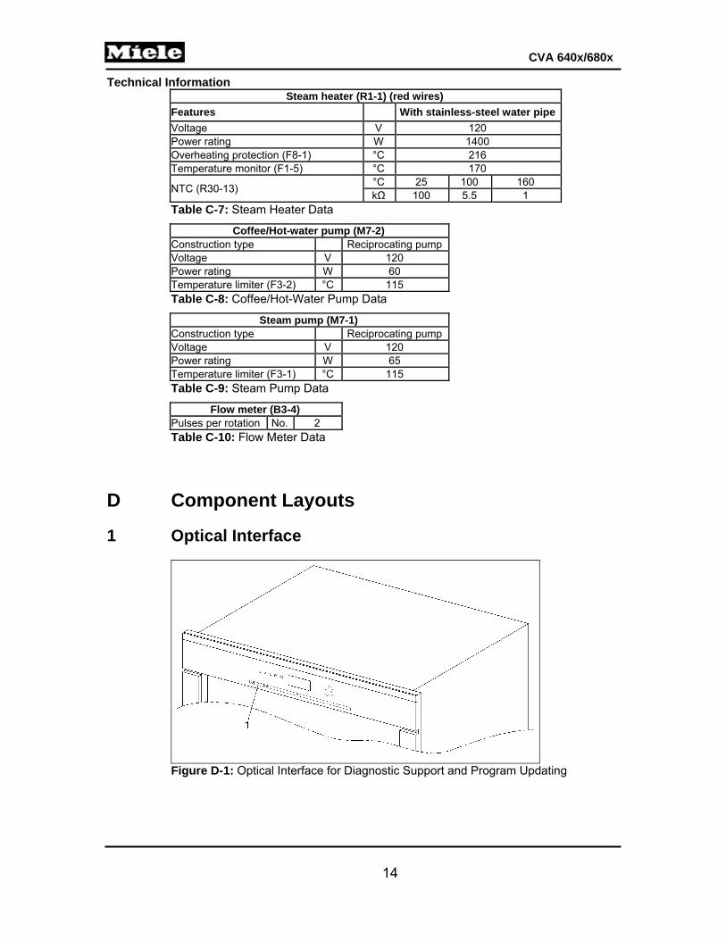
After the brew unit has been activated, if one of the two position switches (Figure 001-10, Item 3 or 4) has not switched within approximately 10 seconds, fault F073 will be indicated (see Section 001-3.11).
Figure 001-10: Brew Unit Microswitches
2.3.2 Electronic Grind Amount Compensation The grind amount compensation balances out variations in grinder settings and coffee types. The grind amount can be set in the customer programming mode for the various coffee types. The setting range is divided into levels 1 to 7, which cover grinding times of 4.6 to 8.3 seconds (± 1.6 seconds ground quantity compensation). To prevent the brewing mechanism from overfilling, the maximum grinding time is limited to 10 seconds.
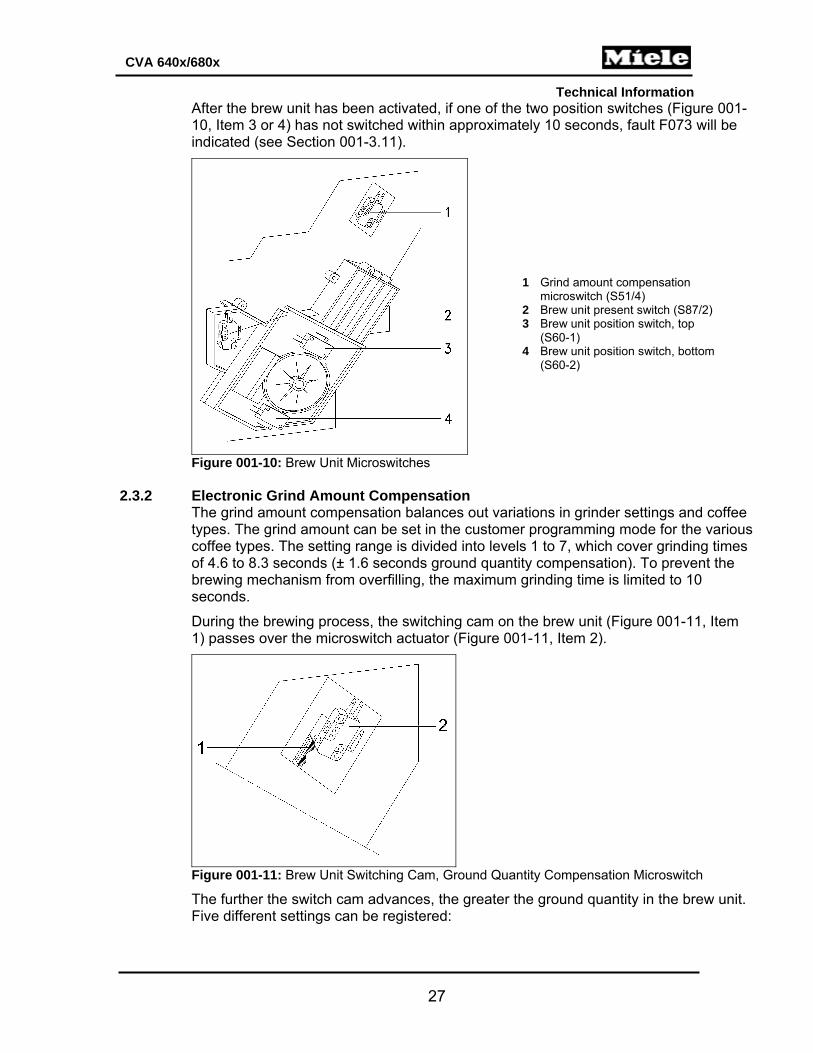
During the brewing process, the switching cam on the brew unit (Figure 001-11, Item 1) passes over the microswitch actuator (Figure 001-11, Item 2).
Figure 001-11: Brew Unit Switching Cam, Ground Quantity Compensation Microswitch
The further the switch cam advances, the greater the ground quantity in the brew unit. Five different settings can be registered:
1 Grind amount compensation microswitch (S51/4)
2 Brew unit present switch (S87/2) 3 Brew unit position switch, top
(S60-1) 4 Brew unit position switch, bottom
(S60-2)

Technical Information
28
CVA 640x/680x
Position Microswitch Position Switching Process
1 In front of the first cam Off
2 On the first cam Off, On
3 Between the two cams Off, On, Off
4 On the second cam Off, On, Off, On
5 Behind the second cam Off, On, Off, On, Off
Table 001-1: Switch Cam Settings
Three volume areas can be measured for the ground quantity; see Figure 001-12. They represent the selectable volume areas on the machine; see Figure 001-13.
Figure 001-12: Measurable Volume Areas 1, 2 and 3
Figure 001-13: Selectable Volume Areas 1, 2 and 3
If the measure quantity varies from the set quantity, then the grinding time will be increased or decreased by approximately 0.2 seconds as appropriate during the next grinding cycle. Because the maximum ground quantity compensation is ±1.6 seconds, this adjustment can be repeated up to 8 times.
2.3.3 Brew Unit Drive, Home Position
If the brew unit is in the home position, the left cam of the double-cam element activates the top microswitch; the bottom microswitch is not switched (Figure 001-14). The cam is in the home position (Figure 001-15).

Technical Information
29
CVA 640x/680x
Figure 001-14: Home Position, Rear View
Figure 001-15: Home Position, Front View
2.3.4 Brew Unit Drive, Compressing Position (Brew Position) The drive moves until the second cam of the double-cam element switches the bottom microswitch, and the top microswitch is no longer switched (Figure 001-16). The cam presses down on the spring (Figure 001-17) and closes the drain valve. The ground coffee is slightly compressed and brewed.

Technical Information
30
CVA 640x/680x
Figure 001-16: Compressing Position, Rear View
Figure 001-17: Compressing Position, Front View
2.3.5 Brew Unit Drive, Drain Position
After the coffee is brewed, the drive moves back until the first cam of the double-cam element activates the bottom microswitch and the top microswitch is switched (Figures 001-18 and 001-19). The tension of the spring is released, the drain valve is opened, and the residual water runs into the drip tray before the coffee puck is dropped.

Technical Information
31
CVA 640x/680x
Figure 001-18: Drain Position, Rear View
Figure 001-19: Drain Position, Front View
2.4 Waste-Container Monitoring
There are two situations where the “Empty waste container” message will be displayed.
Number of pucks in waste container > 15. First puck was deposited in waste container > 48 h ago.
If one of these conditions is met, the “Empty waste container” message will be displayed. See also Section 001-3.31.
2.5 Machine Response after a Power Failure
After a power failure, the machine remains switched off (standby). The fault memory and all modifications made by the operator are saved.
2.6 Safety Concept for Water Intake (CVA 6x05 Only)
2 water inlet valves (1Y63, 2Y63): These solenoids are connected in series in the water path. One solenoid is controlled

Technical Information
32
CVA 640x/680x
by the power electronic and one by the display electronic.
Power electronic (N1-1), display electronic (N1-2): If one electronic is defective, the second solenoid will be closed by the other electronic.
Water container monitoring with 2 float switches (S12-1, S12-3): The bottom float switch monitors the minimum level in the water container. The top float switch switches off the water inlet valves.
Water intake duration: The water intake time is monitored. If the top float switch has not switched after 2 minutes, the water inlet valves are closed.
Drip tray/appliance base plate: If the presence of water is registered by the drip tray contacts, the water inlet valves are closed.
3 Fault Repair
3.1 F001 -- Coffee/Hot Water NTC (R30-14) Short-Circuited
Symptom: NTC temperature as registered by the electronic is > 200°C or the resistance is < approx. 430Ω.
Cause: Coffee/hot water NTC (R30-14) short-circuited. Remedy: 1. Check the connection leads. 2. Replace the connection leads, if necessary. 3. Check the NTC via service mode. See Section 001-4.4.
Note: The approximate resistance values of this NTC are 100kΩ at 77°F (25°C), 5.5kΩ at 212°F (100°C), and 1kΩ at 320°F (160°C).
4. Check the resistance of the NTC at different temperatures and compare to the above values.
5. Replace the NTC, if necessary. See Section 001-4.9. 3.2 F002 -- Coffee/Hot Water NTC (R30-14) Open-Circuited
Symptom: NTC temperature as registered by the electronic is < -10°C or the resistance is > approx. 600kΩ.
Cause: Ambient temperature below 10°C for a long period. With ambient temperatures less than 10°C, the resistance of the NTC increases to a value that is registered as an open circuit by the electronic module.

Technical Information
33
CVA 640x/680x
Remedy:
Note: The ambient temperature must be greater than 15°C for a long period and the appliance can then be used normally. Replacing the electronic module or NTC will not provide a remedy.
Cause: Coffee/hot water NTC (R30-14) open-circuited. Remedy: 1. Check the connection leads. 2. Replace the connection leads, if necessary. 3. Check the NTC via service mode. See Section 001-4.4.
Note: The approximate resistance values of this NTC are 100kΩ at 77°F (25°C), 5.5kΩ at 212°F (100°C), and 1kΩ at 320°F (160°C).
4. Check the resistance of the NTC at different temperatures and compare to the above values.
5. Replace the NTC, if necessary. See Section 001-4.9. 3.3 F003 -- Steam NTC (R30-13) Short-Circuited
Symptom: NTC temperature as registered by the electronic is > 200°C or the resistance is < approx. 430Ω.
Cause: Steam NTC (R30-13) short-circuited. Remedy: 1. Check the connection leads. 2. Replace the connection leads, if necessary. 3. Check the NTC via service mode. See Section 001-4.4.
Note: The approximate resistance values of this NTC are 100kΩ at 77°F (25°C), 5.5kΩ at 212°F (100°C), and 1kΩ at 320°F (160°C).
4. Check the resistance of the NTC at different temperatures and compare to the above values.
5. Replace the NTC, if necessary. See Section 001-4.9. 3.4 F004 -- Steam NTC (R30-13) Open-Circuited
Symptom: NTC temperature as registered by the electronic is < -10°C or the resistance is > approx. 600kΩ.

Technical Information
34
CVA 640x/680x
Cause: Ambient temperature below 10°C for a long period. With ambient temperatures less than 10°C, the resistance of the NTC increases to a value that is registered as an open circuit by the electronic module.
Remedy:
Note: The ambient temperature must be greater than 15°C for a long period and the appliance can then be used normally. Replacing the electronic module or NTC will not provide a remedy.
Cause: Steam NTC (R30-13) open-circuited. Remedy: 1. Check the connection leads. 2. Replace the connection leads, if necessary. 3. Check the NTC via service mode. See Section 001-4.4.
Note: The approximate resistance values of this NTC are 100kΩ at 77°F (25°C), 5.5kΩ at 212°F (100°C), and 1kΩ at 320°F (160°C).
4. Check the resistance of the NTC at different temperatures and compare to the above values.
5. Replace the NTC, if necessary. See Section 001-4.9.
3.5 F010 -- No Water Intake
Symptom: The flow meter (B3-4) is not delivering any pulses within a 6-second interval.
Cause: Water container inserted incorrectly. Remedy: Insert the water container correctly.
Cause: The appliance has not been used for a long period. The pump is dry.
Figure 001-20: Pressure Pump

Technical Information
35
CVA 640x/680x
Remedy: 1. Remove the water tank. 2. Compress the pressure pump, Figure 001-20, and fill it with water. 3. Install the filled pressure pump on the connection for the water tank.
Note: When checking the pump in service mode, hold a magnet over the door contact switch.
4. Activate the appliance pump in the service mode (see Section 001-4.4) and at the same time press water into the system via the pressure pump.
Cause: Hose connections interrupted, blocked or kinked. Remedy: 1. Check hose connections. 2. Replace hoses, if necessary.
Cause: Water container valve jammed or clogged. Remedy: 1. Check water container valve. 2. Replace water container, if necessary.
Cause: Flow meter (B3-4) defective or clogged. Remedy: 1. Check the flow meter in service mode (see Section 001-4.4). 2. Replace the flow meter, if necessary. See Section 001-4.30.
Cause: Steam pump (M7-1) or coffee/hot-water pump (M7-2) defective. Remedy: 1. Check both pumps in service mode; see Section 001-4.4. 2. Replace pump(s), if necessary. See Section 001-4.13.
Warning! In order to avoid possible water system faults (e.g., clogging or blocking of valves), grease, oil or other slip lubricants should never be used when assembling and installing water system parts.
3.6 F017 -- Insufficient Water Intake
Symptom: Less than one pulse at flow meter input within a 7-second interval.
Cause: Water container inserted incorrectly. Remedy: Insert the water container correctly.
Cause: The appliance has not been used for a long period. The pump is dry.
Remedy:

Technical Information
36
CVA 640x/680x
1. Remove the water tank. 2. Compress the pressure pump (see Figure 001-20) and fill it with water. 3. Install the filled pressure pump on the connection for the water tank.
Note: When checking the pump in service mode, hold a magnet over the door contact switch.
4. Activate the appliance pump in the service mode (see Section 001-4.4) and at the same time press water into the system via the pressure pump.
Cause: Hose connections interrupted, blocked or kinked. Remedy: 1. Check hose connections. 2. Replace hoses, if necessary.
Cause: Water container valve jammed or clogged. Remedy: 1. Check water container valve. 2. Replace water container, if necessary.
Cause: Flow meter (B3-4) defective or clogged. Remedy: 1. Check the flow meter in service mode (see Section 001-4.4). 2. Replace the flow meter, if necessary. See Section 001-4.30.
Cause: Steam pump (M7-1) or coffee/hot-water pump (M7-2) defective. Remedy: 1. Check both pumps in service mode; see Section 001-4.4. 2. Replace pump(s), if necessary. See Section 001-4.13.
3.7 F028 -- Too Much Ground Coffee in Brew Unit
Symptom: When preparing beverages using ground coffee, the brew unit is not moving into the “Press” position; see Section 001-2.3.4. It can, however, move back to the reference position.
Cause: Excessive ground coffee was taken in through the chute or there are coffee grounds in
the brew unit. Remedy: 1. Remove the ground coffee. 2. Advise the customer about correct dispensing amounts as outlined in the operating
instructions.
3.8 F040 - Power Electronic EPL (N1-1) Fault
Symptom:

Technical Information
37
CVA 640x/680x
Impermissible state registered at power electronic.
Cause: Reset via power failure. Remedy: Switch the appliance off and back on.
3.9 F041 -- EEPROM Faulty/Data Fault
Symptom: Checksum at switch-on or when switching on out of standby mode triggers a fault.
Cause: Fault while saving data (power failure during data storage). EEPROM defective. Remedy: Replace the power electronic. See Section 001-4.18.
3.10 F042 -- Line Frequency Not Registered
Symptom: No or insufficient zero-crossings (voltage) were calculated during a 6-second interval.
Cause: Frequency fluctuations or power-supply interference. Remedy: Replace the power electronic. See Section 001-4.18.
3.11 F073 -- Brew Unit Fault
Symptom: Brew unit doesn‘t move to the desired position within 6 seconds.
Figure 001-21: Brew Unit Position Switches
After the brew unit is activated, if one of the two microswitches has not been activated within approximately 10 seconds, fault code F073 is indicated.
Cause: Brew unit jammed. Remedy: 1. Disconnect the appliance from the power supply. 2. Remove foreign objects. 3. Clean affected parts.
1 Brew unit position switch, top (S60-1) 2 Brew unit position switch, bottom (S60-2)

Technical Information
38
CVA 640x/680x
Cause: Brew unit drive defective. Remedy: Replace the brew unit drive. See Section 001-4.23.
Note: When re-installing the brew unit drive, make sure that the cam is in the home position. See Section 001-2.3.3.
3.12 F074 -- Ceramic Valve (1M29) Fault
Symptom: Ceramic valve (1M29) is activated, but its position switch (1S60-3) does not detect a new position within 3 seconds.
Cause: 1. Ceramic valve (1M29) defective. 2. Ceramic valve position switch (1S60-3) defective. Remedy: 1. Check plugs and wires. 2. Replace defective plugs and wires. 3. Check the position switch and ceramic valve in service mode; see Section 001-4.4. 4. If either the ceramic valve or its position switch is defective, then replace the
ceramic valve. See Section 001-4.15.
3.13 F076 -- Brew Unit Compression Fault
Symptom: When preparing beverages using coffee beans, the brew unit is not moving into the “Press” position; see Section 001-2.3.4. It can, however, move back to the reference position.
Cause: Grind amount too high or coffee grounds in brew unit. Remedy: Reduce the grind amount; see Section 001-4.1.
Cause: Grind level too coarse. Remedy: Adjust the grind level to a finer setting.
3.14 F077 -- Ceramic Valve (1M29) Initialization Fault
Symptom: Ceramic valve step contact switch (1S51-1) not activated. During initialization, the reference contact is detected multiple times or not at all, OR when approaching or passing over the reference position the reference contact is not detected or is detected in an undefined position.
Cause: Ceramic valve step contact switch (1S51-1) or ceramic valve (1M29) defective. Remedy:

Technical Information
39
CVA 640x/680x
1. Check plugs and wires. 2. Replace defective plugs and wires. 3. Test the ceramic valve and step contact switch in the service mode; see Section
001-4.4. 4. Replace the ceramic valve, if necessary; refer to Section 001-4.15.
3.15 F080 -- Coffee/Hot-Water Heater (R1-2) Not Heating
Symptom: Heater temperature not increasing during heat-up stage. Coffee heater (R1-2) is activated, but temperature increase is < 1°C within a 35-second interval. Temperature increasing too slowly within 1 second.
Cause: Coffee heater NTC (R30-14) defective. Remedy: 1. Check plugs and wires. 2. Replace defective plugs and wires. 3. Check the NTC in service mode; see Section 001-4.4.
Note: The approximate resistance values of this NTC are 100kΩ at 77°F (25°C), 5.5kΩ at 212°F (100°C), and 1kΩ at 320°F (160°C).
4. Check the resistance of the NTC at different temperatures and compare to the above values.
5. Replace the NTC, if necessary. See Section 001-4.9.
Cause: Coffee/hot-water heater (R1-2) not heating. Temperature is lower than 60°C. Remedy: 1. Test the coffee/hot-water heater in service mode. See Section 001-4.4. 2. Replace the heater, if necessary; see Section 001-4.9.
Cause: Heater fuse (F8-2) has blown. An overshoot can blow the fuse on the heater. Remedy: Replace the fuse. See Section 001-4.9.
Note: Because damage to the NTC cannot be ruled out, the coffee/hot-water heater NTC should also be replaced. See Section 001-4.9.
3.16 F081 -- Steam Heater (R1-1) Not Heating
Symptom: Heater temperature not increasing during heat-up stage. Heater (R1-1) is activated, but temperature increase is < 1°C within a 35-second interval. Temperature increasing too slowly within 1 second.
Cause:

Technical Information
40
CVA 640x/680x
Steam heater NTC (R30-13) defective. Remedy: 1. Check plugs and wires. 2. Replace defective plugs and wires. 3. Check the NTC in service mode; see Section 001-4.4.
Note: The approximate resistance values of this NTC are 100kΩ at 77°F (25°C), 5.5kΩ at 212°F (100°C), and 1kΩ at 320°F (160°C).
4. Check the resistance of the NTC at different temperatures and compare to the above values.
5. Replace the NTC, if necessary. See Section 001-4.9.
Cause: Steam heater (R1-1) not heating. Temperature is lower than 60°C. Remedy: 1. Test the steam heater in service mode. See Section 001-4.4. 2. Replace the heater, if necessary; see Section 001-4.9.
Cause: Heater fuse (F8-1) has blown. An overshoot can blow the fuse on the heater. Remedy:
Replace the heater fuse and NTC (since the NTC may also be damaged); see Section 001-4.9.
3.17 F082 -- Coffee/Hot-Water Heater (R1-2) Overheating
Symptom: Heater temperature higher than 123°C for 120 s or longer.
Cause: Coffee heater NTC (R30-14) defective. Remedy: 1. Check plugs and wires. 2. Replace defective plugs and wires. 3. Check the NTC in service mode; see Section 001-4.4.
Note: The approximate resistance values of this NTC are 100kΩ at 77°F (25°C), 5.5kΩ at 212°F (100°C), and 1kΩ at 320°F (160°C).
4. Check the resistance of the NTC at different temperatures and compare to the above values.
5. Replace the NTC, if necessary. See Section 001-4.9.

Technical Information
41
CVA 640x/680x
Note: Because damage to the NTC cannot be ruled out, the coffee/hot-water heater NTC should also be replaced. See Section 001-4.9.
Cause: Coffee/hot-water heater too hot. Temperature is higher than 130°C. An overshoot can cause the fuse to trip. Remedy: 1. Replace the fuse; see Section 001-4.9. 2. Because premature damage cannot be ruled out, also replace the NTC; see
Section 001-4.9. 3.18 F083 -- Steam Heater (R1-1) Overheating
Symptom: Heater temperature higher than 170°C for 120 s or longer.
Cause: Steam heater NTC (R30-13) defective. Remedy: 1. Check plugs and wires. 2. Replace defective plugs and wires. 3. Check the NTC in service mode; see Section 001-4.4.
Note: The approximate resistance values of this NTC are 100kΩ at 77°F (25°C), 5.5kΩ at 212°F (100°C), and 1kΩ at 320°F (160°C).
4. Check the resistance of the NTC at different temperatures and compare to the above values.
5. Replace the NTC, if necessary. See Section 001-4.9.
Note: Because damage to the NTC cannot be ruled out, the coffee/hot-water heater NTC should also be replaced. See Section 001-4.9.
Cause: Steam heater too hot. Temperature is higher than 180°C. An overshoot can cause the fuse to trip. Remedy: 1. Replace the fuse; see Section 001-4.9. 2. Because premature damage cannot be ruled out, also replace the NTC; see
Section 001-4.9. 3.19 F094 -- Water Intake Fault (CVA 6x05 Only)
Symptom: Inlet valves (1Y63, 2Y63) are energized, but after 5 minutes the top switch in the water container (S12-3) has not yet switched.
Cause:

Technical Information
42
CVA 640x/680x
During commissioning, the appliance water intake shutoff valve was closed. Remedy: 1. Open the shutoff valve. 2. Confirm the fault message with OK.
Cause: Hose kinked. Remedy: Lay the hose so that it is not kinked.
Cause: During water intake a large quantity of hot water has been dispensed. The top float in the water container has not switched within 5 minutes. Remedy: Confirm the fault message with OK.
Cause: During water intake the drip tray has been emptied. The top float in the water container has not switched within 5 minutes. Remedy: Confirm the fault message with OK.
Cause: During water intake the water container has been emptied. The top float in the water container has not switched within 5 minutes. Remedy: Confirm the fault message with OK. Cause: Inlet valves (1Y63, 2Y63) defective. Remedy: 1. Check plugs and wires. 2. Replace defective plugs and wires. 3. Check the inlet valves in service mode; see Section 001-4.4. 4. Replace the inlet valves, if necessary; see Section 001-4.17.
3.20 F225 -- Ceramic Valve (2M29) Fault
Symptom: Ceramic valve (2M29) is activated, but its position switch (2S60-3) does not detect a new position within 3 seconds.
Cause: Ceramic valve (2M29) or position switch (2S60-3) defective. Remedy: 1. Check plugs and wires. 2. Replace defective plugs and wires. 3. Check the ceramic valve and position switch in service mode; see Section 001-4.4. 4. If either the ceramic valve or its position switch is defective, then replace the
ceramic valve. See Section 001-4.16.

Technical Information
43
CVA 640x/680x
3.21 F226 -- Ceramic Valve (2M29) Initializing Fault
Symptom: Ceramic valve step contact switch (2S51-1) not activated. During initialization, the reference contact is detected multiple times or not at all, OR when approaching or passing over the reference position the reference contact is not detected or is detected in an undefined position.
Cause: Ceramic valve (2M29) or step contact switch (2S51-1) defective. Remedy: 1. Check plugs and wires. 2. Replace defective plugs and wires. 3. Check the ceramic valve and step contact switch in service mode; see Section
001-4.4. 4. If either the ceramic valve or its step contact switch is defective, then replace the
ceramic valve. See Section 001-4.16. 3.22 F227 -- Cup-Edge Sensor (1B10) Short-Circuited
Symptom: The cup-edge sensor's output voltage as measured by the electronic is > approx. 3.43V.
Cause: Cup-edge sensor (1B10) short-circuited.
Remedy: 1. Check wiring and plugs. 2. Replace defective wiring and/or plugs. 3. Check the sensor in service mode; see Section 001-4.4. 4. Replace the sensor if it is defective. See Section 001-4.38.
3.23 F228 -- Cup-Edge Sensor (1B10) Open-Circuited
Symptom: The cup-edge sensor's output voltage as measured by the electronic is < approx. 11mV.
Cause: Cup-edge sensor (1B10) open-circuited.
Remedy: 1. Check wiring and plugs. 2. Replace defective wiring and/or plugs. 3. Check the sensor in service mode; see Section 001-4.4. 4. Replace the sensor if it is defective. See Section 001-4.38.
3.24 F229 -- Cup-Edge Sensor (2B10) Short-Circuited
Symptom: The cup-edge sensor's output voltage as measured by the electronic is > approx. 3.43V.
Cause:

Technical Information
44
CVA 640x/680x
Cup-edge sensor (2B10) short-circuited.
Remedy: 1. Check wiring and plugs. 2. Replace defective wiring and/or plugs. 3. Check the sensor in service mode; see Section 001-4.4. 4. Replace the sensor if it is defective. See Section 001-4.38.
3.25 F230 -- Cup-Edge Sensor (2B10) Open-Circuited
Symptom: The cup-edge sensor's output voltage as measured by the electronic is < approx. 11mV.
Cause: Cup-edge sensor (1B10) open-circuited.
Remedy: 1. Check wiring and plugs. 2. Replace defective wiring and/or plugs. 3. Check the sensor in service mode; see Section 001-4.4. 4. Replace the sensor if it is defective. See Section 001-4.38.
3.26 F233 -- Cup Protection Switch (S86) Not Active
Symptom: Actuation of the reference/protection contact was not detected with upward initialization.
This fault can occur after switch-on, beverage preparation or a maintenance program.
Cause: Cup protection switch (S86) defective. Remedy: 1. Check plugs and wires. 2. Replace defective plugs and wires. 3. Check the switch in service mode; see Section 001-4.4. 4. Replace the switch if it is defective. See Section 001-4.37.
Cause: Dispenser is not moving all the way up.
When the dispenser adjustment motor (M19) is initialized, its wiring harness is blocking the dispenser from moving upward enough to activate the cup protection switch (S86). Remedy:
Required components:
1 Mat. no. 09818990 Dispenser (cup sensor) conversion kit, including instructions (mat. no. 09821142)
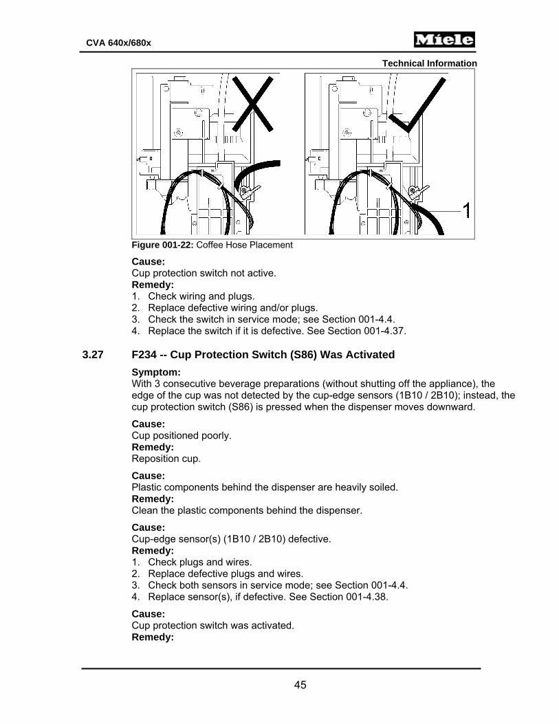
1. On the new dispenser, make sure that the coffee hose is laid correctly (Figure 001-22, Item 1).
2. Install the new dispenser as outlined in the conversion instructions.
Technical Information
45
CVA 640x/680x
Figure 001-22: Coffee Hose Placement
Cause: Cup protection switch not active. Remedy: 1. Check wiring and plugs. 2. Replace defective wiring and/or plugs. 3. Check the switch in service mode; see Section 001-4.4. 4. Replace the switch if it is defective. See Section 001-4.37.
3.27 F234 -- Cup Protection Switch (S86) Was Activated
Symptom: With 3 consecutive beverage preparations (without shutting off the appliance), the edge of the cup was not detected by the cup-edge sensors (1B10 / 2B10); instead, the cup protection switch (S86) is pressed when the dispenser moves downward.
Cause: Cup positioned poorly. Remedy: Reposition cup.
Cause: Plastic components behind the dispenser are heavily soiled. Remedy: Clean the plastic components behind the dispenser.
Cause: Cup-edge sensor(s) (1B10 / 2B10) defective. Remedy: 1. Check plugs and wires. 2. Replace defective plugs and wires. 3. Check both sensors in service mode; see Section 001-4.4. 4. Replace sensor(s), if defective. See Section 001-4.38.
Cause: Cup protection switch was activated. Remedy:

Technical Information
46
CVA 640x/680x
Note: The switch state can be displayed in service mode; see Section 001-4.4.
3.28 F235 -- Display Electronic EPB (N1-2) Communication Fault
Cause: Communication to display electronic EPB (N1-2) is faulty. Remedy: 1. Check all wires and plugs. See Section 001-4.43 and the wiring diagram, as
needed. 2. Replace any defective plugs or wiring.
3.29 F236 -- Auxiliary Electronic EPZ (N1-25) Communication Fault
Cause: Communication to auxiliary electronic EPZ (N1-25) is faulty. Remedy: 1. Check all wires and plugs. See Section 001-4.42 and the wiring diagram, as
needed. 2. Replace any defective plugs or wiring.
Note: Because the power electronic communicates with the display electronic via the auxiliary electronic (see the wiring diagram for reference), any wiring problems with the auxiliary electronic will automatically make the power electronic think that there’s also a communication fault with the display electronic, thereby triggering a concurrent F235 fault. If both F235 and F236 are stored in the fault memory, check the auxiliary electronic-power electronic connection (the 11-pin wiring harness) first and remedy as needed.
3.30 "X Servings until Descaling" Shown in Display
Cause: The maximum permitted flow of coffee/hot water or the maximum time for steam dispensing has been reached. The values monitored for this depend on the set water hardness. See Table C-4.
Remedy: Descale the appliance; see the operating instructions.
3.31 "Empty Drip Tray" Message, Even Though Drip Tray Is Not Full
Cause: Water is flowing out of the brew unit and touching the contacts in the machine. The drip tray contacts are incorrectly sensing a “full drip tray”. Remedy: Install the drip tray conversion kit (mat. no. 09763690) as per the instructions.
3.32 "Replace Drip Tray" Message, Even Though Drip Tray Is Inserted
Cause: Contact springs are dirty or covered with film (rinse aid from the dishwasher).

Technical Information
47
CVA 640x/680x
Remedy: 1. Shut off the appliance. 2. Remove and clean the drip tray. 3. Clean the contact springs using, e.g., isopropyl or rubbing alcohol.
3.33 “Empty Waste Container” Message, But Waste Container Is Not Full
Cause: If the waste container has not been emptied in the past 48 hours, the message Empty waste container will automatically appear. Remedy: No fault! Advise the customer of this automatic message.
Cause: The waste container was emptied while the appliance was shut off. Emptying of the waste container was not registered by the electronic. After 48 hours the message Empty waste container will appear automatically. Remedy: No fault! Advise the customer of this automatic message.
3.34 ”Fill Milk Container” Message Not Displayed
Symptom: The electronic is not recognizing that the milk container is empty.
Cause: The milk container lid was cleaned in a dishwasher. When the milk container lid is cleaned in a dishwasher, water will remain in the lid. This water electrically “connects” the milk container sensor blades. Therefore, the electronic thinks that the milk container is full.
Series modification: 1. The operating instructions have been modified. 2. The lid has been modified so that it can be better cleaned in a dishwasher.
Remedy: 1. Replace the milk container lid. 2. Advise the customer that the milk container lid should be cleaned by hand (see the
operating instructions). 3.35 Built-In Depths Different
Symptom: If coffee machines are combined with other built-in units, they are positioned approx. 2mm deeper in the niche.
Cause: Sealing strips missing. These coffee machines are suitable for building-in in housing units with integrated sealing strips. If these sealing strips are missing, the machine is seated 2mm deeper in the niche. Remedy: Install the adhesive strips kit (mat. no. 7716270).

Technical Information
48
CVA 640x/680x
Note: These adhesive strips replace the strips missing from the housing unit and ensure that machines are flush.
3.36 Door Jams when Opening
Cause: The coupling piece is not lubricated and jams in the brew unit. The coupling piece on the interior of the appliance door, Figure 001-23, has not been lubricated in accordance with the operating instructions. It jams in the brew unit. Remedy: 1. Lubricate the coupling piece, Figure 001-23. 2. Advise the customer that the coupling piece must be lubricated in accordance with
the operating instructions.
Figure 001-23: Coupling Piece on Inside of Door
3.37 Coffee or Espresso Too Cold
Cause: Machine settings.
Remedy:
Note: Measure the temperature half an inch (1 centimeter) below the dispenser, not in the cup. The temperature should be 187°F (± 3°F).
1. Pre-warm cups. 2. Set the temperature for coffee and espresso to maximum; see Section 001-4.1. 3. Set the grinding setting at least one level lower (finer). 4. Increase the grind (ground coffee) amount; see Section 001-4.1. 5. Activate pre-brewing; see Section 001-4.1.
Note: Additional increase in brewing temperature will burn the coffee and ruin its taste.
3.38 Milk Froth Unsatisfactory or Sputtering
Cause: The milk pipework has not been cleaned sufficiently by the customer. Remedy:

Technical Information
49
CVA 640x/680x
Advise the customer about the correct cleaning of the pipework in accordance with the operating instructions.
3.39 No or Very Little Coffee Flowing from Spout
Symptom: If the coffee/hot-water pump is operated in the service mode, it operates normally and pumps water.
Cause: The coffee/hot-water pump does not create sufficient pressure for the brew unit. Remedy: Replace the coffee/hot-water pump. See Section 001-4.13.
3.40 Coffee Tastes Too Bitter
Symptom: The prepared coffee tastes too bitter or strong. After only a few servings of coffee have been prepared, there is a considerable quantity of wasted ground coffee next to the brew unit.
Cause: The appliance has been set with extreme settings. The ground quantity compensation is at maximum. Remedy:
Note: The change in grinding grade only takes full effect after several servings have been prepared.
1. Reduce the grinding grade by sliding the lever one to two settings to the right. 2. Reduce the ground quantity; see Section 001-4.1. 3. To ensure that the ground quantity compensation can set correctly, reset the
appliance to standard settings; see Section 001-4.3. 4. If the problem occurs again, check the ground quantity switch contact; see Section
001-3.41. 3.41 Coffee Grounds Next to the Brew Unit
Symptom: After approximately 5 coffee servings, there is a large amount of coffee grounds next to the brew unit.
Cause: The holder for the ground quantity step contact switch (Figure 001-24, Item 1) has broken off. The switch remains in the correct position but it moves during the brewing process. See the function description for grind amount compensation, Section 001-2.3.2.
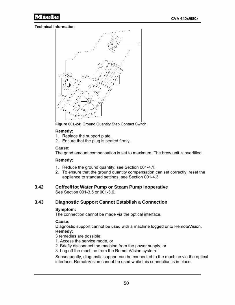
Technical Information
50
CVA 640x/680x
Figure 001-24: Ground Quantity Step Contact Switch
Remedy: 1. Replace the support plate. 2. Ensure that the plug is seated firmly.
Cause: The grind amount compensation is set to maximum. The brew unit is overfilled.
Remedy:
1. Reduce the ground quantity; see Section 001-4.1. 2. To ensure that the ground quantity compensation can set correctly, reset the
appliance to standard settings; see Section 001-4.3. 3.42 Coffee/Hot Water Pump or Steam Pump Inoperative
See Section 001-3.5 or 001-3.6. 3.43 Diagnostic Support Cannot Establish a Connection
Symptom: The connection cannot be made via the optical interface.
Cause: Diagnostic support cannot be used with a machine logged onto RemoteVision. Remedy: 3 remedies are possible:
1. Access the service mode, or 2. Briefly disconnect the machine from the power supply, or 3. Log off the machine from the RemoteVision system.
Subsequently, diagnostic support can be connected to the machine via the optical interface. RemoteVision cannot be used while this connection is in place.

Technical Information
51
CVA 640x/680x
To deactivate the optical interface again, depending on the selected remedy: 1. Quit the machine service mode, or 2. Briefly disconnect the machine from the power supply again, or 3. Log on the machine to the RemoteVision system.
After a maximum of 1 minute, the RemoteVision system can be used again. 3.44 Pump Running Constantly
Symptom: At first use or after the appliance is switched on, the pump is constantly pumping water into the drip tray.
Cause: There is a plastic fragment in the 3-part connector (in the direction of pump flow). Despite the obstruction, water flow is strong enough that no fault will be displayed (F10 or F17). Instead, it will take a long time for the flow meter to register sufficient pulses. Remedy: Replace the 3-part connector. See Figure 001-25.
Figure 001-25: Three-Part Connector on Flow Meter
3.45 Milk Froth Stream is Inconsistent
Symptom: During milk froth preparation, the milk froth stream is not constant.
Cause: Software fault. Imprecise temperature control.
Series modification: Software modification. All machines after index 12 have the improved software. Remedy: 1. Update software. 2. For machines up to index 10, also install the new flow meter (mat. no. 09725380).
3.46 Empty Milk Container Not Detected
Symptom: The electronic is not recognizing that the milk container is empty.
Cause: The milk container lid was cleaned in a dishwasher. When the milk container lid is
1 Flow meter 2, 4, 5 Hoses 3 3-part connector

Technical Information
52
CVA 640x/680x
cleaned in a dishwasher, water will remain in the lid. This water electrically “connects” the milk container sensor blades. Therefore, the electronic thinks that the milk container is full.
Series modification: 1. The operating instructions have been modified. 2. The lid has been modified so that it can be better cleaned in a dishwasher.
Remedy: 1. Replace the milk container lid. 2. Advise the customer that the milk container lid should be cleaned by hand (see the
operating instructions).
4 Service 4.1 Drink Settings (Customer Programming)
4.1.1 CVA 640x
Initial requirements: Switch the appliance on.
Accessing:
Press the touchpad.
Acknowledgement indicator:
The display shows the Parameter menu.
Options:
Note: If no control is operated for 15 s, the display automatically goes back one level without saving.
1. Touch or until the desired drink is displayed. 2. Press OK. 3. Touch or until the desired function is marked. 4. Touch or until the desired setting is marked.

Technical Information
53
CVA 640x/680x
Function Setting Standard setting
Portion size
Espresso: 30 - 250 ml 35 ml for solo espresso; 60 ml with cappuccino or latte macchiato
Coffee: 30 - 250 ml 125 ml
Milk froth: 1 - 60 s 15 s with cappuccino or latte macchiato; 20 s for solo milk froth
Hot milk: 1 - 80 s 20 s with cappuccino or latte macchiato; 35 s for solo hot milk
Large coffee: 30 - 250 ml 160 ml Hot water: 30 - 250 ml 125 ml
Ground quantity setting (does not apply to milk froth, hot milk or hot water)
Level 1 (4.6 s grinding time)
Level 3
Level 2 (5.2 s grinding time) Level 3 (5.8 s grinding time) Level 4 (6.4 s grinding time) Level 5 (7.1 s grinding time) Level 6 (7.6 s grinding time) Level 7 (8.3 s grinding time)
Brew temperature (does not apply to milk froth, hot milk or hot water)
Minimum (96°C)
Medium Low (98°C) Medium (100°C) High (102°C) Maximum (104°C)
Pre-brewing Off
Off Short (1.5 s) Long (3.0 s)
Table 001-2: Drink Settings (Customer Programming), CVA 640x
Back (without saving): Press the touchpad.
Save and quit: 1. Press the OK touchpad. The selected drink will be prepared. 2. Press the OK touchpad as soon as Save is shown and the desired portion size has
been reached. The portion size is saved for all subsequent servings of the drink.
3. Press the touchpad. The machine is switched off.
Quit (without saving):
Press the touchpad. The machine is switched off.
4.1.2 CVA 680x
Initial requirements: Switch the appliance on.
Accessing: 1. Press the Main menu touchpad. 2. Press the Drinks touchpad. 3. Press the Change touchpad.
Acknowledgement indicator: Drink-size options are displayed.

Technical Information
54
CVA 640x/680x
Options:
Note: If no touchpads are pressed for 15 s, the display will automatically go back one level.
To scroll, swipe a finger to the left or right across the display or press the < or > touchpad.
Function Setting Standard setting
Portion size (press the Save touchpad as soon as it appears and the drink size is satisfactory; the drink size will be saved for all future preparations of that particular beverage)
Espresso: 30 - 250 ml 35 ml for solo espresso; 60 ml with cappuccino or latte macchiato
Coffee: 30 - 250 ml 125 ml
Milk froth: 1 - 60 s 15 s with cappuccino or latte macchiato; 20 s for solo milk froth
Hot milk: 1 - 80 s 20 s with cappuccino or latte macchiato; 35 s for solo hot milk
Large coffee: 30 - 250 ml 160 ml Hot water: 30 - 250 ml 125 ml
Coffee jug: 3 cups (375 ml) to 8 cups (1000 ml)
3 cups: 375 ml 4 cups: 500 ml 5 cups: 625 ml 6 cups: 750 ml 7 cups: 875 ml 8 cups: 1000 ml
Ground quantity setting (does not apply to milk froth, hot milk or hot water)
Level 1 (4.6 s grinding time)
Level 3
Level 2 (5.2 s grinding time) Level 3 (5.8 s grinding time) Level 4 (6.4 s grinding time) Level 5 (7.1 s grinding time) Level 6 (7.6 s grinding time) Level 7 (8.3 s grinding time)
Brew temperature (does not apply to milk froth, hot milk or hot water)
Minimum (96°C)
Medium Low (98°C) Medium (100°C) High (102°C) Maximum (104°C)
Pre-brewing Off
Off Short (1.5 s) Long (3.0 s)
Reset drinks to factory settings
Yes: All customer drink settings (except for profile settings) are restored to their factory defaults.
No: All customer drink settings remain unchanged and will not be restored to their factory settings.
Table 001-3: Drink Settings (Customer Programming), CVA 680x
Back (without saving): Press the Back touchpad.
Save and quit:

Technical Information
55
CVA 640x/680x
1. Press the OK touchpad. The selected drink will be prepared.
2. Press the touchpad. The machine is switched off.
Quit (without saving):
Press the touchpad. The machine is switched off. 4.2 Machine Settings (Customer Programming) 4.2.1 CVA 640x
Initial requirements: Switch the appliance on.
Accessing:
Press the touchpad.
Acknowledgement indicator: The display shows the Settings menu.
Options:
Note: If no control is operated for 15 s, the display automatically goes back one level without saving.
If the language setting is incorrect, follow the symbol to access the language function. The language setting remains as selected even if standard settings are reset.
1. Touch or until the desired function is displayed. 2. Press OK. 3. Touch or until the desired setting is marked.
Function Setting Standard setting
Language
Bahasa malaysia (Malaysian) cestina (Czech) dansk (Danish)
deutsch (German)
Deutschland (Germany) Luxemburg (Luxembourg)Österreich (Austria)
Schweiz (Switzerland)
english
Australia United Kingdom Hong Kong India Ireland Canada Mexico New Zealand Singapore South Africa USA

Technical Information
56
CVA 640x/680x
Function Setting Standard setting
Language
espanol (Spanish)
Chile México España (Spain) EE UU (USA)
francais (French)
Belgique (Belgium) France Canada Luxembourg Suisse (Switzerland)
hrvatski (Croatian)
italiano (Italian) Italia (Italy) Svizzera (Switzerland)
magyar (Hungarian)
nederlands (Dutch) Belgien (Belgium) Nederland (the Netherlands)
norsk (Norwegian) polski (Polish) português (Portuguese) Română (Romanian) Slovenčina (Slovak) Slovenščina (Slovene) Srpski (Serbian) suomi (Finnish) svenska (Swedish) türkce (Turkish) griechisch (Greek)
russisch (Russian)
Russia Kazachstan Latvia Lithuania Estonia
ukrainisch (Ukranian)
arabic
chinesisch (Chinese) China
Hong Kong
Japanese
Persian
Time
Display
On (time of day is shown constantly) Off Off (time of day is not shown when the appliance is switched off) Night dimming (time of day is not shown between 11 pm and 5 am when the appliance is switched off)
Time format
24 h (time displayed in 24 h clock format)
24 h
12 h (time displayed in 12 h clock format)
Set Current time of day can be set
Date Set the date with the and touchpads.

Technical Information
57
CVA 640x/680x
Function Setting Standard setting
Timer (select Timer 1 or Timer 2)
Set
Switch on at (if the timer is activated, the appliance will switch on at the set time on the selected days)
Switch off after (the appliance will switch off after the set time has elapsed)1
00:15 to 09:00 [h:min]
00:30 [h:min]
Switch off at (if the timer is activated, the appliance will switch off at the set time on the selected days)
Day of the week
Monday to Sunday
Mark the desired days and accept them.
Accept
Activate
Switch on at Mark the desired setting and accept it. The timer is activated.
Switch off at
Accept
Eco mode On
Steam heater activated only occasionally
On
Off Steam heater constantly activated
Lighting
Brightness
Machine switched on
Level 0 to 7 (Level 0 = Lighting switched off)
Level 4
Machine switched off
Level 0 to 7 Level 0
Switch off after
00:00 to 06:00 [h:min]
The light will switch off after the set time has elapsed.
00:15 [h:min]
Info No. of drinks
Coffee drinks total
The number of serving cycles carried out is displayed.
Total number of servings
Espresso
Coffee
Cappuccino
Latte Macchiato
Large coffee
Caffè latte
Hot milk
Milk froth
Hot water

Technical Information
58
CVA 640x/680x
Function Setting Standard setting
Info Number of servings until
Descaling
The number of servings until descaling is required is displayed.
Degreasing the brew unit
The number of servings until brew unit degreasing is required is displayed.
System lock On
System lock is switched on. The machine can be safeguarded against accidental switch-on.
Off
Off System lock is switched off.
Water hardness 2,
3
Soft (0 - 4 grains per gallon) Very hard
Medium (5 - 9 grains per gallon)
Hard (10 - 18 grains per gallon)
Very hard (> 18 grains per gallon)
Display brightness
Level 1 to 7 Darker to brighter Level 4
Volume Buzzer tones Level 0 – 7 Level 0 = Switched
off
Level 7
Keypad tones Level 0 – 7 Level 7
Plumbed water connection
On
Off
Showroom program
On
The demonstration mode has been activated. The appliance can be operated but heating will not take place.
Off
Off The demonstration mode is deactivated. Heating will take place.
Factory default
Do not reset All modifications made by the customer will not be reset to standard settings.
Reset
All modifications (except the language setting) will be reset to standard settings. The showroom program remains unchanged. Settings made in service programming mode and in service mode remain unchanged.
Table 001-4: Machine Settings (Customer Programming), CVA 640x 1 Only available with Timer 1. 2 To prevent limescale buildup in the flow-through heater, descaling must be carried out more
frequently with hard water. 3 The set water hardness will affect when “50 servings until descaling” is displayed; see Table C-4.

Technical Information
59
CVA 640x/680x
Back (without saving): Press the touchpad.
Save and quit: 1. Press the OK touchpad. The setting is saved.
2. Press the touchpad. The machine is switched off.
Quit (without saving):
Press the touchpad. The machine is switched off. 4.2.2 CVA 680x
Initial requirements: Switch the appliance on.
Accessing: 1. Press the Main menu touchpad. 2. Press the Settings touchpad.
Acknowledgement indicator: Customer programming options are displayed.
Options:
Note: If no touchpads are pressed for 15 s, the display will automatically go back one level.
If the language setting is incorrect, follow the symbol to access the language function. The language setting remains as selected even if standard settings are reset.
1. To scroll, swipe a finger to the left or right across the display or press the < or > touchpad.
2. Press the touchpad for the desired function.
Function Setting Standard setting
Language
Bahasa malaysia (Malaysian) cestina (Czech) dansk (Danish)
deutsch (German)
Deutschland (Germany) Luxemburg (Luxembourg)Österreich (Austria)
Schweiz (Switzerland)
english
Australia United Kingdom Hong Kong India Ireland Canada Mexico New Zealand Singapore South Africa USA

Technical Information
60
CVA 640x/680x
Function Setting Standard setting
Language
espanol (Spanish)
Chile México España (Spain) EE UU (USA)
francais (French)
Belgique (Belgium) France Canada Luxembourg Suisse (Switzerland)
hrvatski (Croatian)
italiano (Italian) Italia (Italy) Svizzera (Switzerland)
magyar (Hungarian)
nederlands (Dutch) Belgien (Belgium) Nederland (the Netherlands)
norsk (Norwegian) polski (Polish) português (Portuguese) Română (Romanian) Slovenčina (Slovak) Slovenščina (Slovene) Srpski (Serbian) suomi (Finnish) svenska (Swedish) türkce (Turkish) griechisch (Greek)
russisch (Russian)
Russia Kazachstan Latvia Lithuania Estonia
ukrainisch (Ukranian)
arabic
chinesisch (Chinese) China
Hong Kong
Japanese
Persian
Time
Display
On (time of day is shown constantly) Off Off (time of day is not shown when the appliance is switched off) Night dimming (time of day is not shown between 11 pm and 5 am when the appliance is switched off)
Time format
24 h (time displayed in 24 h clock format)
24 h
12 h (time displayed in 12 h clock format)
Set Current time of day can be set
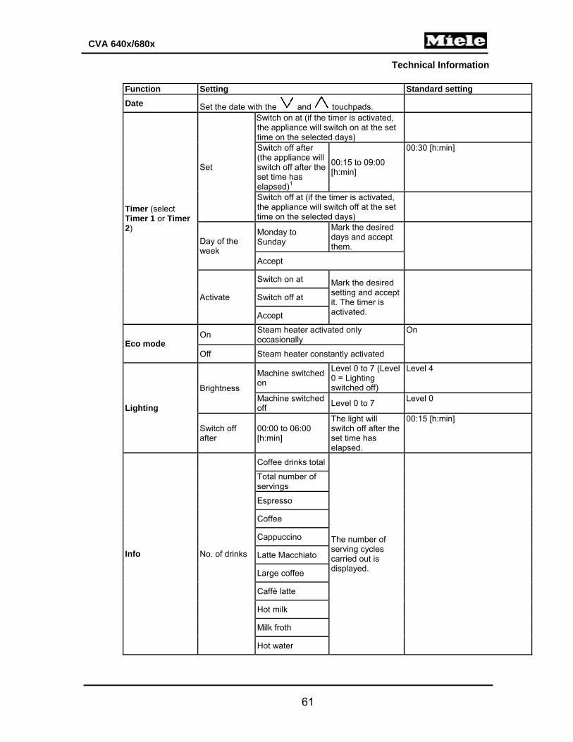
Technical Information
61
CVA 640x/680x
Function Setting Standard setting
Date Set the date with the and touchpads.
Timer (select Timer 1 or Timer 2)
Set
Switch on at (if the timer is activated, the appliance will switch on at the set time on the selected days)
Switch off after (the appliance will switch off after the set time has elapsed)1
00:15 to 09:00 [h:min]
00:30 [h:min]
Switch off at (if the timer is activated, the appliance will switch off at the set time on the selected days)
Day of the week
Monday to Sunday
Mark the desired days and accept them.
Accept
Activate
Switch on at Mark the desired setting and accept it. The timer is activated.
Switch off at
Accept
Eco mode On
Steam heater activated only occasionally
On
Off Steam heater constantly activated
Lighting
Brightness
Machine switched on
Level 0 to 7 (Level 0 = Lighting switched off)
Level 4
Machine switched off
Level 0 to 7 Level 0
Switch off after
00:00 to 06:00 [h:min]
The light will switch off after the set time has elapsed.
00:15 [h:min]
Info No. of drinks
Coffee drinks total
The number of serving cycles carried out is displayed.
Total number of servings
Espresso
Coffee
Cappuccino
Latte Macchiato
Large coffee
Caffè latte
Hot milk
Milk froth
Hot water

Technical Information
62
CVA 640x/680x
Function Setting Standard setting
Info Number of servings until
Descaling
The number of servings until descaling is required is displayed.
Degreasing the brew unit
The number of servings until brew unit degreasing is required is displayed.
System lock On
System lock is switched on. The machine can be safeguarded against accidental switch-on.
Off
Off System lock is switched off.
Water hardness 2,
3
Soft (0 - 4 grains per gallon) Very hard
Medium (5 - 9 grains per gallon)
Hard (10 - 18 grains per gallon)
Very hard (> 18 grains per gallon)
Display brightness
Level 1 to 7 Darker to brighter Level 4
Volume Buzzer tones Level 0 – 7 Level 0 = Switched
off
Level 7
Keypad tones Level 0 – 7 Level 7
Plumbed water connection
On On
Off
Dispenser adjustment
On Dispenser adjustment is switched on. On
Off Dispenser adjustment is switched off.
Showroom program
On
The demonstration mode has been activated. The appliance can be operated but heating will not take place.
Off
Off The demonstration mode is deactivated. Heating will take place.
Factory default
Do not reset All modifications made by the customer will not be reset to standard settings.
Reset
All modifications (except the language setting) will be reset to standard settings. The showroom program remains unchanged. Settings made in service programming mode and in service mode remain unchanged.
Table 001-5: Machine Settings (Customer Programming), CVA 680x 1 Only available with Timer 1. 2 To prevent limescale buildup in the flow-through heater, descaling must be carried out more
frequently with hard water. 3 The set water hardness will affect when “50 servings until descaling” is displayed; see Table C-4.
Back (without saving):

Technical Information
63
CVA 640x/680x
Press the Back touchpad.
Save and quit: 1. Press the OK touchpad. The setting is saved.
2. Press the touchpad. The machine is switched off.
Quit (without saving):
Press the touchpad. The machine is switched off. 4.3 Service Programming Mode 4.3.1 CVA 640x
Initial requirements: Switch the appliance off.
Accessing: 1. Press and hold Profile.
2. Press once. 3. Release Profile. 4. Press Profile again 5 times; hold on the 5th time until the programming mode is
displayed.
Acknowledgement indicator: Programming mode is displayed, along with the service programming functions.
Options:
Note: If no touchpad is pressed for 15 s, the display automatically goes back one level without saving.
1. Touch or to scroll to the desired programming function (see Table 001-6). Press OK to select the function.
2. After selecting a function, touch or to scroll to the desired option. See Table 001-6. Press OK to select the option.
3. To go back to the previous menu, touch or until Back is marked. 4. Press OK.
Function Options Description Reset Cancel Reset is not carried out.
Carry out a reset All modified settings will be reset to standard settings. The language remains unchanged. The showroom program remains unchanged. The fault memory remains unchanged.
Appliance type Plumbed water connection
Available Model with plumbed water connection (CVA 6405)
Not available Model without plumbed water connection (CVA 6401)
Note: Access has to be completed within two seconds.

Technical Information
64
CVA 640x/680x
Function Options Description Appliance type Warming
drawer Available Model with connected warming
drawer Not available Model without connected warming
drawer Restart Cancel Restart not carried out.
Restart A restart is equivalent to a break in power supply. All settings remain unchanged. The showroom program remains unchanged. The fault memory remains unchanged.
Descale 1 Do not reset Descaling counter is not reset.
Reset Descaling counter is reset. The lock is lifted.
Degrease the brew unit
Do not reset Degreasing counter is not reset.
Reset Degreasing counter is reset.
Clean milk system
Do not reset Cleaning counter is not reset. Reset Cleaning counter is reset. The
lock is lifted. Table 001-6: Service Programming Settings, CVA 640x
1 To avoid damage to the appliance, the machine should be descaled after service work has been completed.
Back (without saving): Press the touchpad.
Save and quit: 1. Press the OK touchpad. All settings are saved.
2. Press the touchpad. The machine is switched off.
Quit (without saving):
Press the touchpad. The machine is switched off. 4.3.2 CVA 680x
Initial requirements: Switch the appliance off.
Accessing: 1. Press and hold the Back touchpad.
2. Press once. 3. Release Back. 4. Press Back again 5 times; hold on the 5th time until the programming mode is
displayed.
Acknowledgement indicator: Programming mode and the programming functions are displayed.
Note: Access has to be completed within two seconds.

Technical Information
65
CVA 640x/680x
Options:
Note: If no touchpad is pressed for 15 s, the display automatically goes back one level without saving.
Function Options Description Reset Reset & restore
all settings? Yes All modified settings will be reset
to standard settings. The language remains unchanged. The showroom program remains unchanged. The fault memory remains unchanged.
No Reset is not carried out. Service Appliance type Main water
connection (Present/Not present)
Plate warmer (Present/Not present)
Descale 1 Reset descaling program? (Yes/No)
Descaling counter is/is not reset (if reset, the lock will be lifted).
Degrease the brew unit
Reset brew unit degrease settings? (Yes/No)
Degreasing counter is/is not reset.
Clean the milk pipework
Reset milk pipework cleaning setting? (Yes/No)
Cleaning counter is/is not reset.
Table 001-7: Service Programming Settings, CVA 680x 1 To avoid damage to the appliance, the machine should be descaled after service work has been
completed.
Back (without saving): Press the Back touchpad.
Save and quit: 1. Press the OK touchpad. All settings are saved.
2. Press the touchpad. The machine is switched off.
4.4 Service Mode 4.4.1 CVA 640x
Initial requirements: Switch the appliance off.
Accessing: 1. Press and hold Profile.
2. Press once. 3. Release Profile. 4. Press Profile again 3 times; hold on the 3rd time until service mode is displayed.

Technical Information
66
CVA 640x/680x
Acknowledgement indicator: Service mode is displayed, along with the service functions.
Options:
Note: If no touchpad is pressed for 15 s, the display automatically goes back one level without saving.
Touch or to scroll to the desired service function (see Table 001-8). Press OK to select the function.
Function Displays Description
Software version
EPB e.g. ID 02983 V1 ID number and version of the auxiliary electronic EPB (N1-2)
EPL e.g. ID 02984 V1 ID number and version of the power electronic EPL (N1-1)
LNG e.g. 4774 N/A
EPZ e.g. 02882 V1 ID number and version of the display module EPZ (N1-25)
Fault memory
OK All logged faults are shown.
Delete Cancel Fault memory is not deleted.
Delete Fault memory is deleted.
Component
H3 (serving-area light)On Off
1M29 (ceramic valve)
Initialize
The ceramic valve is moved through its positions and then back to the home position. To avoid mechanical damage, always initialize as a last step.
Step counterclockwise The ceramic valve is moved counterclockwise.
Step clockwise The ceramic valve is moved clockwise.
Continuous counterclockwise
The ceramic valve is moved continuously counterclockwise. Press OK to stop.
Continuous clockwise The ceramic valve is moved continuously clockwise. Press OK to stop.
Position 1
The ceramic valve is stepped to the appropriate position.
Position 2 Position 3 Position 4 Position 5 Position 6 Position 7 Position 8
2M29 (ceramic valve 2)
Same as 1M29 above
Note: Access has to be completed within two seconds.

Technical Information
67
CVA 640x/680x
Function Displays Description
Component
M26 (brew unit drive)1
Initialization The brew unit is passed through all its positions and finishes at the rest position.
Continuously upwards The brew unit is advanced to the top end setting.
Continuously downwards The brew unit is advanced to the bottom end setting.
Rest position The brew unit is advanced to the appropriate position.
Drain position Compression position
M25 (grinder) On, off
M7-2 (coffee/hot-water pump)
Phase chopping Flow meter displays 22 pulses per second
Pulse package Flow meter displays 5 pulses per second
Continuously The pump is activated continuously (flow meter displays 26 pulses per second)
M7-1 (steam pump) Same as M7-2 above
Empty the system Empty the water container or remove it from the appliance.
R2 (coffee/hot-water heater) 3
OK R30-14 (coffee/hot-water heater NTC) reading is displayed
Press OK to activate If the temperature rises, the flow-through heater is in order.
Press OK again to deactivate
R1 (steam heater) 3
OK R30-13 (steam heater NTC) reading is displayed
Press OK to activate If the temperature rises, the flow-through heater is in order.
Press OK again to deactivate
K1-80 (warming-drawer relay)
On, off
1Y63 / 2Y63 (intake valve)
On, off
M24 (milk valve) 1
Initialization The milk valve is stepped through its positions; press OK.
Hot milk position
The milk valve is stepped to the appropriate position. Press OK to start/stop activation.
Hot milk latte position
Milk froth position
Rinsing position
Priming position
Container rinsing position
Milk valve care position

Technical Information
68
CVA 640x/680x
Function Displays Description
Component M28 (air valve) 1
Initialization The air valve is stepped through its positions.
Open position
The air valve is stepped to the appropriate position.
Closed position
Priming position
Sensor
R30-14 value (coffee/hot-water heater NTC) The temperature in the coffee/hot-water heater is displayed.
R30-13 value (steam heater NTC) The temperature in the steam heater is displayed.
B3-4 value (flow meter) The number of pulses per second provided by the flow meter is displayed.
Switch status
S12-2 (drip tray monitor switch)
0 Not installed 1 Installed
S24 (door contact switch)
0 Closed 1 Open
S12-1/S12-3 (water tank level switches)
See Table 001-9.
1B3-14 (beans container sensor)
0 Not installed or installed and empty
1 Installed and full
S60-1/S60-2 (brew unit position switch)
See Table 001-10.
S87-2 (brew unit present switch)
0 Installed and locked
1 Not installed or installed and not locked
S51-4 (ground quantity step contact switch)
0 Activated
1 Not activated
S87-5 (coffee chute monitor switch)
0 Closed 1 Open
S87-4 (waste container present switch)
0 Installed
1 Not installed
S12-4 (milk container level sensor)
0 Installed and not empty
1 Not installed or installed and empty
1S51-1 (ceramic valve 1 step contact switch)
0 Activated
1 Not activated
1S51-2 (ceramic valve 2 step contact switch)
0 Activated
1 Not activated
1S60-3 (ceramic valve 1 positioning switch)
0 Activated
1 Not activated
2S60-3 (ceramic valve 2 positioning switch)
0 Activated 1 Not activated
S87-6 (spout monitor switch)
0 Not installed
1 Installed
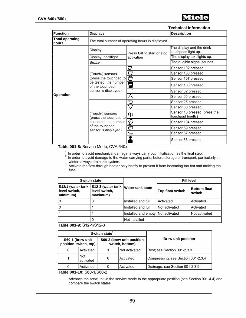
Technical Information
69
CVA 640x/680x
Function Displays Description
Total operating hours
The total number of operating hours is displayed.
Operation
Display Press OK to start or stop activation
The display and the drink touchpads light up.
Display backlight The display text lights up.
Buzzer The audible signal sounds.
(Touch-) sensors (press the touchpad to be tested; the number of the touchpad sensor is displayed)
Sensor 102 pressed
Sensor 103 pressed
Sensor 107 pressed
Sensor 108 pressed
Sensor 82 pressed
Sensor 65 pressed
(Touch-) sensors (press the touchpad to be tested; the number of the touchpad sensor is displayed)
Sensor 26 pressed
Sensor 66 pressed
Sensor 16 pressed (press the touchpad briefly)
Sensor 104 pressed
Sensor 69 pressed Sensor 67 pressed
Sensor 68 pressed
Table 001-8: Service Mode, CVA 640x 1 In order to avoid mechanical damage, always carry out initialization as the final step. 2 In order to avoid damage to the water-carrying parts, before storage or transport, particularly in
winter, always drain the system. 3 Activate the flow-through heater only briefly to prevent it from becoming too hot and melting the
fuse.
Switch state
Water tank state
Fill level
S12/1 (water tank level switch, minimum)
S12-3 (water tank level switch, maximum)
Top float switch Bottom float switch
0 0 Installed and full Activated Activated
0 1 Installed and full Not activated Activated
1 1 Installed and empty Not activated Not activated
1 0 Not installed - -
Table 001-9: S12-1/S12-3
Switch state1
Brew unit position S60-1 (brew unit position switch, top)
S60-2 (brew unit position switch, bottom)
0 Activated 1 Not activated Rest; see Section 001-2.3.3
1 Not activated
0 Activated Compressing; see Section 001-2.3.4
0 Activated 0 Activated Drainage; see Section 001-2.3.5
Table 001-10: S60-1/S60-2 1 Advance the brew unit in the service mode to the appropriate position (see Section 001-4.4) and
compare the switch states.
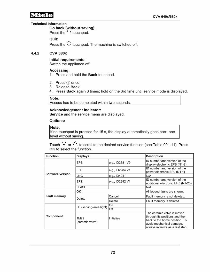
Technical Information
70
CVA 640x/680x
Go back (without saving): Press the touchpad.
Quit:
Press the touchpad. The machine is switched off. 4.4.2 CVA 680x
Initial requirements: Switch the appliance off.
Accessing: 1. Press and hold the Back touchpad.
2. Press once. 3. Release Back. 4. Press Back again 3 times; hold on the 3rd time until service mode is displayed.
Acknowledgement indicator: Service and the service menu are displayed.
Options:
Note: If no touchpad is pressed for 15 s, the display automatically goes back one level without saving.
Touch or to scroll to the desired service function (see Table 001-11). Press OK to select the function.
Function Displays Description
Software version
EPB e.g., ID2881 V9 ID number and version of the display electronic EPB (N1-2)
ELP e.g., ID2984 V1 ID number and version of the power electronic EPL (N1-1)
LNG e.g., ID4941 N/A
EPZ e.g., ID2882 V1 ID number and version of the additional electronic EPZ (N1-25)
FLASH N/A
Fault memory
OK All logged faults are shown.
Delete Cancel Fault memory is not deleted.
Delete Fault memory is deleted.
Component
H3 (serving-area light)On Off
1M29 (ceramic valve)
Initialize
The ceramic valve is moved through its positions and then back to the home position. To avoid mechanical damage, always initialize as a last step.
Note: Access has to be completed within two seconds.

Technical Information
71
CVA 640x/680x
Function Displays Description
Component
1M29 (ceramic valve)
Step counterclockwise The ceramic valve is moved counterclockwise.
Step clockwise The ceramic valve is moved clockwise.
Continuous counterclockwise
The ceramic valve is moved continuously counterclockwise. Press OK to stop.
Continuous clockwise The ceramic valve is moved continuously clockwise. Press OK to stop.
Position 1
The ceramic valve is stepped to the appropriate position.
Position 2 Position 3 Position 4 Position 5 Position 6 Position 7 Position 8
2M29 (ceramic valve 2)
Same as 1M29 above
M26 (brew unit drive)1
Initialization The brew unit is passed through all its positions and finishes at the rest position.
Continuously upwards The brew unit is advanced to the top end setting.
Continuously downwards The brew unit is advanced to the bottom end setting.
Rest position The brew unit is advanced to the appropriate position.
Drain position Compression position
M25 (grinder) On, off
M7-2 (coffee/hot-water pump)
Phase chopping Flow meter displays 22 pulses per second
Pulse package Flow meter displays 5 pulses per second
Continuously The pump is activated continuously (flow meter displays 26 pulses per second)
M7-1 (steam pump) Same as M7-2 above
R2-1 (coffee/hot-water heater) 3
OK R30-14 (coffee/hot-water heater NTC) reading is displayed
Press OK to activate If the temperature rises, the flow-through heater is in order.
Press OK again to deactivate
R1-1 (steam heater) 3
OK R30-13 (steam heater NTC) reading is displayed
Press OK to activate If the temperature rises, the flow-through heater is in order.
Press OK again to deactivate
K1-80 (warming-drawer relay)
On, off

Technical Information
72
CVA 640x/680x
Function Displays Description
Component
1Y63 / 2Y63 (intake valve)
On, off
M19 (dispenser adjustment motor)
Initialize Dispenser is moved upward and then into the basic position.
Continuous top Dispenser moved to the end (top) position.
Continuous bottom Dispenser moved to the bottom position.
Basic Dispenser moved to the basic position.
Logo Dispenser moved to the position where the Miele logo can be clearly seen.
Service Dispenser moved to the position where the dispensing cover can be removed.
Dispense Dispenser moved to the dispensing position.
M24 (milk valve) 1
Initialization The milk valve is stepped through its positions; press OK.
Hot milk position
The milk valve is stepped to the appropriate position. Press OK to start/stop activation.
Hot milk/latte position
Milk froth position
Rinsing position
Priming position
Container rinsing position
Milk valve care position
M28 (air valve) 1
Initialization The air valve is stepped through its positions.
Open position
The air valve is stepped to the appropriate position.
Closed position
Priming position
Sensor values
R30-14 value (coffee/hot-water heater NTC) The temperature in the coffee/hot-water heater is displayed.
R30-13 value (steam heater NTC) The temperature in the steam heater is displayed.
1B10 (cup-edge sensor)
2B10 (cup-edge sensor)
B3-4 value (flow meter) The number of pulses per second provided by the flow meter is displayed.
S12-2 (drip tray monitor switch)
0 Not installed 1 Installed

Technical Information
73
CVA 640x/680x
Function Displays Description
Switch status
S24 (door contact switch)
0 Closed 1 Open
1B3-14/2B3-14 (beans container sensors)
0 Not installed or installed and empty
1 Installed and full or not installed
S60-1 (brew unit position switch)
See Table 001-10.
S60-2 (brew unit position switch)
See Table 001-10.
S87-2 (brew unit present switch)
0 Installed and locked
1 Not installed or installed and not locked
S51-4 (ground quantity step contact switch)
0 Activated
1 Not activated
S87-5 (coffee chute monitor switch)
0 Closed 1 Open
S87-4 (waste container present switch)
0 Installed
1 Not installed
S12-1/S12-3 (water tank level switches)
See Table 001-9.
S12-4 (milk container level sensor)
0 Installed and not empty
1 Not installed or installed & empty
1S51-1 (ceramic valve 1 step contact switch)
0 Activated
1 Not activated
1S51-2 (ceramic valve 2 step contact switch)
0 Activated
1 Not activated
1S60-3 (ceramic valve 1 positioning switch)
0 Activated
1 Not activated
2S60-3 (ceramic valve 2 positioning switch)
0 Activated
1 Not activated
S87-6 (spout monitor switch)
0 Not installed
1 Installed
S86 (cup protection switch)
0 Not installed
1 Installed
Total operating hours
The total number of operating hours is displayed.
Operation
Display backlight Press OK to start or stop activation
The display and the drink touchpads light up. The display text lights up.
Loudspeaker A test melody will be played.
Touch Reaction Swipe a finger across the display.
Sensors Press the touchpad to be tested.
A tone will sound.
Exit
Table 001-11: Service Mode, CVA 680x
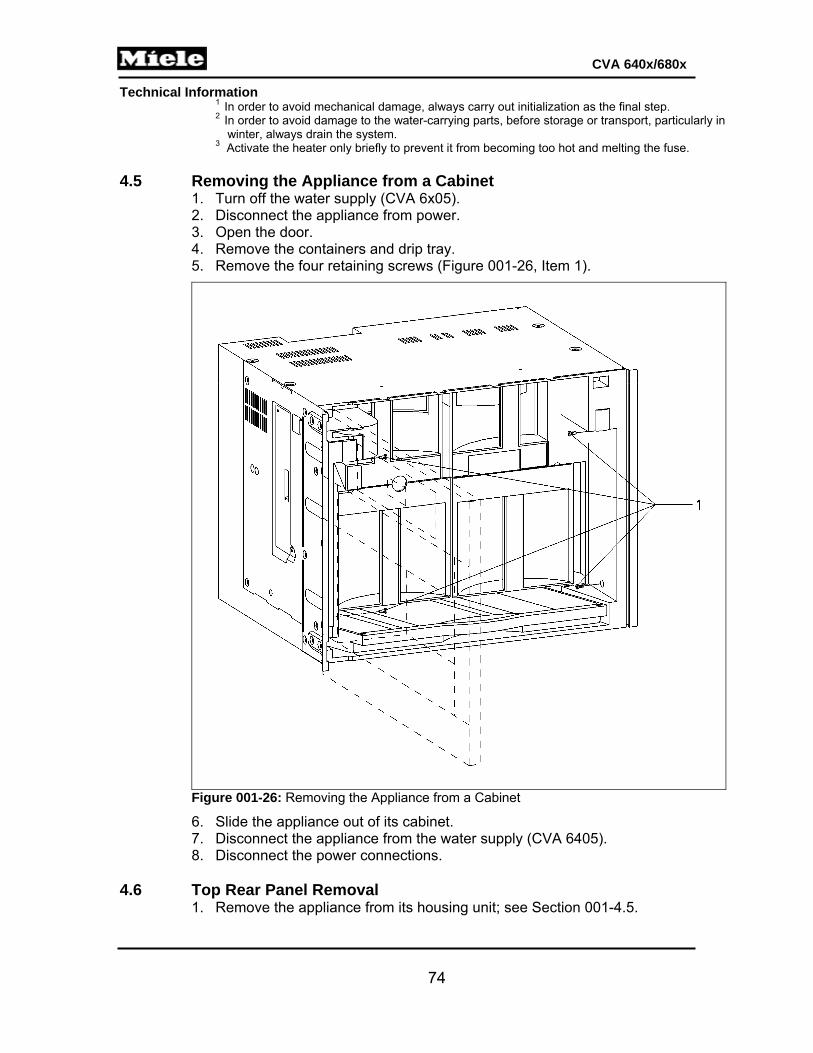
Technical Information
74
CVA 640x/680x
1 In order to avoid mechanical damage, always carry out initialization as the final step. 2 In order to avoid damage to the water-carrying parts, before storage or transport, particularly in
winter, always drain the system. 3 Activate the heater only briefly to prevent it from becoming too hot and melting the fuse.
4.5 Removing the Appliance from a Cabinet
1. Turn off the water supply (CVA 6x05). 2. Disconnect the appliance from power. 3. Open the door. 4. Remove the containers and drip tray. 5. Remove the four retaining screws (Figure 001-26, Item 1).
Figure 001-26: Removing the Appliance from a Cabinet
6. Slide the appliance out of its cabinet. 7. Disconnect the appliance from the water supply (CVA 6405). 8. Disconnect the power connections.
4.6 Top Rear Panel Removal
1. Remove the appliance from its housing unit; see Section 001-4.5.

Technical Information
75
CVA 640x/680x
2. Remove the top cover screws (four T10s and four T20s). 3. Remove the top cover. 4. Remove the four screws securing the top rear panel (two T10s and two T20s). See
Figure 001-27.
Note: There is an additional screw on the left side of the top rear panel that is not shown in the illustration below.
Figure 001-27: Top Rear Panel Removal
5. Take off the top rear panel and use needlenose pliers to disconnect the ground wire.
4.7 Bottom Rear Panel Removal
1. Remove the appliance from its housing unit; see Section 001-4.5. 2. Remove the top rear panel; see Section 001-4.6. 3. Remove the two T10 screws securing the inlet valve mounting bracket to the
bottom rear panel (CVA 6x05 only). See Figure 001-28, Item 1. 4. Remove the two T10 screws securing the sides of the bottom rear panel (Figure
001-28, Item 2) and take off the panel.

Technical Information
76
CVA 640x/680x
Figure 001-28: Bottom Rear Panel and Service Door Screws
4.8 Preparing Machine for Servicing 1. Remove the appliance from its housing unit; see Section 001-4.5. 2. Remove the top rear panel; see Section 001-4.6. 3. Remove the T10 screw securing the right side of the service door. See Figure 001-
28, Item 3. 4. Remove the connection cable between the auxiliary electronic and the power
board from its guide. 5. Open the service door. See Figure 001-29.
Figure 001-29: Service Door, Open
1
2 2
3

Technical Information
77
CVA 640x/680x
4.9 Heater (Steam R1-1 or Coffee/Hot-Water R1-2) Removal
1. Remove the appliance from its housing unit; see Section 001-4.5. 2. Remove the top rear panel; see Section 001-4.6. 3. Prepare the machine for servicing; see Section 001-4.8.
Figure 001-30: Service Door Open, Showing Heaters
4. Remove the T20 screw securing the appropriate heater assembly (shown at Figure 001-32, Item 1).
5. Release the horseshoe clip holding the two halves of the heater housing together. 6. Separate the housing from the heater and carefully pull off the plastic bottom
support. 7. Remove the spring clips from the water line connections (Figure 001-31, Items 1
and 2).
Figure 001-31: Heater Water Line Connections
8. Unscrew the NTC (Figure 001-32, Item 2). 9. Remove the fuse screw (Figure 001-32, Item 4) and the fuse.
1 Steam heater 2 Coffee/hot-water heater
1 Spring clips 2 Water line connections

Technical Information
78
CVA 640x/680x
10. Remove the ground screw (Figure 001-32, Item 3) and the ground wire. 11. Disconnect all other electrical connections from the heater.
Figure 001-32: Heater Assembly
Warning! Important for reassembly: To prevent damage to the NTC or heater, do not secure the NTC too tightly. There should be a gap of approx. 0.5mm between the NTC and the heater.
4.10 Heater NTC (Steam R30-13 or Coffee/Hot-Water R30-14) Removal
See Section 001-4.9. 4.11 Heater Temperature Limiter (Steam F1-5 or Coffee/Hot-Water F1-8) Removal
See Section 001-4.9. 4.12 Heater Fuse (Steam F8-1 or Coffee/Hot-Water F8-2) Removal
See Section 001-4.9. 4.13 Pump (Steam M7-1 or Coffee/Hot-Water M7-2) Removal
1. Remove the appliance from its housing unit; see Section 001-4.5. 2. Remove the top rear panel; see Section 001-4.6. 3. Remove the bottom rear panel; see Section 001-4.7. 4. Prepare the machine for servicing; see Section 001-4.8. 5. Remove the spring clip from the Teflon hose connection at the top of the
appropriate pump and disconnect the Teflon hose. 6. Disconnect the pump's electrical connection. 7. Remove the two T10 screws securing each of the pump's metal mounting brackets
(top and bottom). These brackets are not shown in the below illustration but the screw locations are shown at Figure 001-33, Item 1.
1 Heater screw (T20) 2 NTC 3 Ground screw (T20) 4 Fuse screw (T20)

Technical Information
79
CVA 640x/680x
8. Remove the pump from the appliance. 9. Disconnect the silicone hose from the bottom of the pump (arrow, Figure 001-33). 10. Disconnect the wiring from the temperature limiter (Figure 001-33, Item 2). 11. Insert small needlenose pliers into one side of the temperature limiter's retaining
clip (see arrows at Figure 001-33, Item 2); pull forward to release. Repeat with the other side of the clip.
12. Slide the temperature limiter out of its notch in the pump. 13. Pull off the pump rubber brackets (top and bottom).
Figure 001-33: Pump Assembly
Warning! In order to avoid possible water system faults (e.g., clogging or blocking of valves), grease, oil or other slip lubricants should never be used when assembling and installing water system parts.
4.14 Pump Temperature Limiter (Steam F3-1 or Coffee/Hot-Water F3-2) Removal
See Section 001-4.13. 4.15 Ceramic Valve 1M29 Removal
Note: Ceramic valve 1M29 is the one that is installed upside down.
1. Remove the appliance from its housing unit; see Section 001-4.5. 2. Remove the top rear panel; see Section 001-4.6. 3. Remove the bottom rear panel; see Section 001-4.7. 4. Prepare the machine for servicing; see Section 001-4.8. 5. Remove the three spring clips securing the water lines at the front and side of the
valve; disconnect the three water lines from the valve. 6. Disconnect the electrical connection at the top of the valve.
1 Pump retaining screws 2 Temperature limiter
Technical Information
80
CVA 640x/680x
7. Remove the two black T10 screws securing the valve to the outside of the left side panel.
8. Pull the valve out of the appliance. 9. Disconnect the two spring clips securing the water lines at the back of the valve,
and disconnect the two water lines from the valve. 4.16 Ceramic Valve 2M29 Removal
Note: Ceramic valve 2M29 is the one that is installed right side up.
1. Remove the appliance from its housing unit; see Section 001-4.5. 2. Remove the top rear panel; see Section 001-4.6. 3. Remove the bottom rear panel; see Section 001-4.7. 4. Prepare the machine for servicing; see Section 001-4.8. 5. Remove the four screws (three T10s and one T20) securing the left side access
panel; take off the panel. 6. Pull the valve out through the side of the appliance. 7. Remove the five spring clips securing the water lines to the valve; disconnect all
five water lines. 8. Disconnect the drain hose from the valve. 9. Disconnect the electrical connection from the valve. 10. Push the retaining tab on the valve's black plastic mounting bracket away from the
valve, and slide the bracket down and off of the valve. 4.17 Inlet Valve Removal (CVA 6x05 Only)
1. Remove the appliance from its housing unit; see Section 001-4.5. 2. Remove the top rear panel; see Section 001-4.6. 3. Remove the bottom rear panel; see Section 001-4.7. 4. Disconnect the electrical connections from the inlet valve assembly. 5. Unscrew the intake hose from the inlet valve assembly.
4.18 EPL Power Electronic (N1-1) Removal
1. Remove the appliance from its housing unit; see Section 001-4.5. 2. Remove the top rear panel; see Section 001-4.6. 3. Disconnect all electrical connections from the power electronic. 4. Release the electronic's retainers (four) using needlenose pliers. See Figure 001-
34. 5. Remove the power electronic from the appliance.

Technical Information
81
CVA 640x/680x
Figure 001-34: EPL Power Electronic (N1-1) Removal
4.19 Coffee Chute Monitor Switch (S87-5) Removal
1. Remove the appliance from its housing unit; see Section 001-4.5. 2. Prepare the machine for servicing; see Section 001-4.8. 3. Open the appliance door. 4. Take out all of the containers. 5. Pull off the grinding-grade adjustment handle. See Figure 001-35.
Figure 001-35: Adjustment Lever Handle
6. Remove the T10 screws securing the beans container guide. See Figure 001-36, Item 1.

Technical Information
82
CVA 640x/680x
Figure 001-36: Bean Container Guide Retaining Screws
7. Remove the beans container guide. 8. Slide the grinding-grade adjustment lever all the way to the right (arrow, Figure
001-37). 9. Remove the three T10 screws securing the grinder (Figure 001-37, Item 2).
Figure 001-37: Grinder Screws

Technical Information
83
CVA 640x/680x
10. Remove the T10 screw securing the side of the chute to the grinder (Figure 001-38, Item 1).
11. Remove the screw securing the back of the chute (Figure 001-38, Item 2). 12. Pull the chute out from the rear of the housing. 13. Disconnect the wiring harness. 14. Release the coffee chute monitor switch (Figure 001-38, Item 3) from the chute.
Figure 001-38: Chute Monitor Switch and Screws
4.20 Beans Container Sensor (1B3-14, 2B3-14) Removal
1. Remove the appliance from its housing unit; see Section 001-4.5. 2. Prepare the machine for servicing; see Section 001-4.8. 3. Open the appliance door. 4. Take out the beans container. 5. Pull off the grinding-grade adjustment handle. See Figure 001-35. 6. Remove the T10 screws securing the beans container guide. See Figure 001-36,
Item 1. 7. Remove the beans container guide and disconnect the four-pin wiring harness. 8. Turn the beans container guide upside down. 9. Using a small flathead screwdriver, press in on the retainers on the sides of each
sensor housing (Figure 001-39). 10. Slide the sensor housings out of the beans container guide. 11. Release the sensors from their housings and feed them back through the beans
container guide.
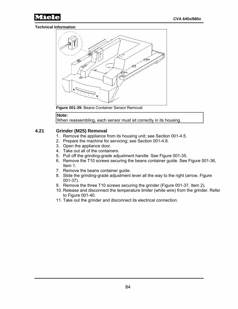
Technical Information
84
CVA 640x/680x
Figure 001-39: Beans Container Sensor Removal
Note: When reassembling, each sensor must sit correctly in its housing.
4.21 Grinder (M25) Removal
1. Remove the appliance from its housing unit; see Section 001-4.5. 2. Prepare the machine for servicing; see Section 001-4.8. 3. Open the appliance door. 4. Take out all of the containers. 5. Pull off the grinding-grade adjustment handle. See Figure 001-35. 6. Remove the T10 screws securing the beans container guide. See Figure 001-36,
Item 1. 7. Remove the beans container guide. 8. Slide the grinding-grade adjustment lever all the way to the right (arrow, Figure
001-37). 9. Remove the three T10 screws securing the grinder (Figure 001-37, Item 2). 10. Release and disconnect the temperature limiter (white wire) from the grinder. Refer
to Figure 001-40. 11. Take out the grinder and disconnect its electrical connection.

Technical Information
85
CVA 640x/680x
Figure 001-40: Grinder and Temperature Limiter
4.22 Grinder Temperature Limiter (F3-3) Removal
1. Remove the grinder; see Section 001-4.21. 2. Release the temperature limiter from its retainer on the grinder (refer to Figure 001-
40). 3. Disconnect the temperature limiter from the grinder (white wire). 4. Cut the cable tie. 5. Remove the grinder temperature limiter from the appliance.
4.23 Brew Unit Drive (M26) Removal 1. Remove the appliance from its housing unit; see Section 001-4.5. 2. Prepare the machine for servicing; see Section 001-4.8. 3. Release the four locking tabs securing the brew unit drive cover and take off the
cover. 4. Disconnect the red-and-black wiring harness from the brew unit drive (Figure 001-
41, Item 2).

Technical Information
86
CVA 640x/680x
Figure 001-41: Brew Unit Drive
5. Open the appliance door. 6. Take out all of the containers. 7. Release the brew unit and remove it from the appliance (Figure 001-42).
Figure 001-42: Brew Unit Removal
8. Remove the five T10 screws securing the brew unit drive; see Figure 001-43, Item 1. 9. Remove the white cam. 10. Remove the brew unit drive from the rear of the appliance.
1 Grind amount compensation microswitch
2 Brew unit drive

Technical Information
87
CVA 640x/680x
Figure 001-43: Brew Unit Drive Retaining Screws
6. Release and disconnect the hose from the brew unit drive. 7. Release the three switches from the brew unit drive.
Note: When re-installing the brew unit drive, ensure that the white cam is in the home position. See Section 001-2.3.3.
4.24 Brew Unit Present Switch (S87-2) Removal
See Section 001-4.23. 4.25 Brew Unit Position Switch (S60-1, S60-2) Removal
See Section 001-4.23. 4.26 Grind Amount Step Contact Switch (S51-4) Removal
1. Remove the appliance from its housing unit; see Section 001-4.5. 2. Prepare the machine for servicing; see Section 001-4.8. 3. Disconnect all wiring from the grind amount step contact switch (refer to Figure
001-41, Item 1, for location). 4. Release and remove the grind amount step contact switch.
4.27 Door Contact Switch (S24) Removal
1. Remove the appliance from its housing unit; see Section 001-4.5. 2. Prepare the machine for servicing; see Section 001-4.8. 3. Remove the six T10 screws securing the right side panel. 4. Take off the right side panel. 5. Pull the door contact switch out of its housing in the upper left-hand corner of the
plastic casing until its plug is visible. 6. Disconnect the door contact switch from the plug.

Technical Information
88
CVA 640x/680x
Note: When reassembling: To facilitate reassembly, secure the plug and wiring.
4.28 Removing the Drip Tray Contact Springs from Inside the Appliance
1. Remove the appliance from its housing unit; see Section 001-4.5. 2. Remove the top rear panel; see Section 001-4.6. 3. Remove the bottom rear panel; see Section 001-4.7. 4. Prepare the machine for servicing; see Section 001-4.8. 5. Use small needlenose pliers to disconnect the electrical connection from each
contact spring. 6. Remove the two T10 screws securing the small tray underneath the brew unit
drive. Take off the tray. 7. Remove the three T10 screws securing the upper interior casing to the lower
interior casing around the contact springs (one screw is to the left of the springs and two are to the right).
8. Separate the upper interior casing from the lower interior casing as much as possible, using appropriate tools to prop up the upper interior casing, so that the contact springs are accessible.
9. Squeeze each spring together and pull it up and off the lower interior casing. 4.29 Water Tank Level Switch (S12-1 or S12-3) Removal
1. Remove the appliance from its housing unit; see Section 001-4.5. 2. Prepare the machine for servicing; see Section 001-4.8. 3. Remove the six T10 screws securing the right side panel. 4. Take off the right side panel. 5. Remove the ten T10 screws securing the inside right side panel (black plastic). 6. Take off this panel. 7. Remove the T10 screw securing the appropriate level switch holder. 8. Disconnect the switch at the connector and remove it from the machine.
4.30 Flow Meter (B3-4) Removal
1. Remove the appliance from its housing unit; see Section 001-4.5. 2. Remove the bottom rear panel; see Section 001-4.7. 3. Prepare the machine for servicing; see Section 001-4.8. The flow meter is located
at Figure 001-44, Item 1.

Technical Information
89
CVA 640x/680x
Figure 001-44: Flow Meter
4. Disconnect the silicone hoses from the flow meter (diagonal arrows, Figure 001-45).
5. Disconnect the electrical connection from the flow meter. 6. Release the flow meter from its plastic support (Figure 001-45, Item 2)
Figure 001-45: Flow Meter (1) and Plastic Support (2)
Warning! In order to avoid possible water system faults (e.g., clogging or blocking of valves), grease, oil or other slip lubricants should never be used when assembling and installing water system parts.

Technical Information
90
CVA 640x/680x
4.31 Waste Container Present Switch (S87-4) Removal 1. Remove the appliance from its housing unit; see Section 001-4.5. 2. Remove the top rear panel; see Section 001-4.6. 3. Remove the bottom rear panel; see Section 001-4.7. 4. Prepare the machine for servicing; see Section 001-4.8. 5. Open the service door. 6. Feed a T10 screwdriver through the access hole in the appliance. See Figure 001-
46.
Note: Remove the left side panel (10 screws) for easier access.
Figure 001-46: Access Hole for Waste Container Monitor Switch
7. Remove the T10 screw securing the waste container present switch holder. 8. Pull the switch out of its housing and disconnect it at the connector. 9. Remove the switch from the appliance, cutting cable ties as necessary.
4.32 RemoteVision Module Removal (CVA 680x Only)
1. Remove the appliance from its housing unit; see Section 001-4.5. 2. Remove the top rear panel; see Section 001-4.6. 3. Remove the bottom rear panel; see Section 001-4.7. 4. Squeeze the two retaining tabs on the sides of the module together. 5. Slide the module out through the bottom rear panel to remove.
4.33 Inner Door Cover Removal
1. Disconnect the appliance from the power supply. 2. Open the appliance door. 3. Take off the service cover (arrow, Figure 001-47).

Technical Information
91
CVA 640x/680x
Figure 001-47: Service Cover
4. Disconnect and remove the hose (Figure 001-48).
Figure 001-48: Hose on Inner Door Cover
5. Remove the 8 T10 screws securing the cover (Figure 001-49, Item 1).

Technical Information
92
CVA 640x/680x
Figure 001-49: Inner Door Cover Screws
6. Take off the cover and disconnect the hose from the inside. 4.34 Dispenser Adjustment Motor (M19) Removal (CVA 680x Only)
1. Disconnect the appliance from the power supply. 2. Open the appliance door. 3. Take off the service cover (arrow, Figure 001-47). 4. Remove the T10 screw securing the auxiliary electronic cover (refer to Figure 001-
51, Item 1); take off this cover. 5. Disconnect the wiring harness from the dispenser adjustment motor. See Figure
001-50, Item 1 6. Remove the two T10 screws securing the motor to the dispenser housing. See
Figure 001-50, Item 2. 7. Pull off the wedge bracket at the base of the motor spindle. See Figure 001-50,
Item 3. 8. Slide the motor up and out of the dispenser housing to remove.

Technical Information
93
CVA 640x/680x
Figure 001-50: Dispenser Adjustment Motor M19
4.35 Spout Monitor Switch (S87-6) Removal 4.35.1 CVA 640x
1. Remove the inner door cover; see Section 001-4.32. 2. Slide the switch out of its housing. Refer to Figure D-2 or D-3, Item 14, for location. 3. Cut cable ties as necessary. 4. Pull the wiring out of its guide. 5. Disconnect the electrical connection from the switch.
4.35.2 CVA 680x
1. Remove the inner door cover; see Section 001-4.32. 2. Remove the two T10 screws securing the spout holder (Figure 001-51, Item 1). 3. Remove the two T10 screws securing the “pin” bracket behind the spout holder
(Figure 001-51, Item 2). 4. Take off the spout holder and “pin” bracket, cutting cable ties as necessary. 5. Disconnect the wiring harness from the spout monitor switch. See Figure 001-52,
Item 1. 6. Slide the spout monitor switch out of the spout holder.
2
3
1

Technical Information
94
CVA 640x/680x
Figure 001-51: Spout Holder and Pin Bracket, CVA 680x
Figure 001-52: Spout Monitor Switch
1
2
1

Technical Information
95
CVA 640x/680x
4.36 Dispensing-Area Light (H3) Removal 4.36.1 CVA 640x
1. Take off the spout cover and spout assembly, then open the appliance door. 2. Remove the inner door cover; see Section 001-4.32. 3. Release the spring clip securing the Teflon hose in front of the spout holder and
light assembly on the inside of the door; take off the hose. 4. Remove the two T10 screws securing the hose assembly in front of the spout
holder and light assembly on the inside of the door; take off this hose assembly. 5. Remove the two T10 screws securing the spout holder to the inside of the door;
take out the spout holder. 6. Remove the T10 screw and washer securing the light assembly to the inside of the
door. 7. Disconnect the electrical connection from the light assembly. 8. Pull the light out of the spout.
Note: Make sure that the red seal is installed on the Teflon hose before reinstalling it in front of the spout holder.
4.36.2 CVA 680x
1. Remove the inner door cover; see Section 001-4.32. 2. Remove the dispenser adjustment motor; see Section 001-4.34. 3. Close the appliance door, take off the spout cover and spout assembly, then open
the appliance door again. 4. Remove the two T10 screws securing the spout holder (Figure 001-51, Item 1). 5. Remove the two T10 screws securing the “pin” bracket behind the spout holder
(Figure 001-51, Item 2). 6. Take off the spout holder and “pin” bracket, cutting cable ties as necessary. 7. Release the spring clip securing the Teflon hose in front of the lighting assembly
and disconnect the hose. 8. Remove the T10 screw securing the hose bracket in front of the lighting assembly
(Figure 001-53, Item 1) and take off this bracket. 9. Remove the T10 screw and washer securing the lighting assembly (Figure 001-53,
Item 2).

Technical Information
96
CVA 640x/680x
Figure 001-53: Hose Bracket and Lighting Assembly
10. Remove the T10 screws securing the lighting assembly mounting bracket (circles, Figure 001-54); take off this bracket.
Figure 001-54: Lighting Assembly Mounting Bracket
11. Unsnap the lenses from the bracket at the front of the dispenser. 12. Pull the lighting assembly down and out of the dispenser. 13. Disconnect the wiring harness from the lighting assembly.
2
1

Technical Information
97
CVA 640x/680x
4.37 Cup Protection Switch (S86) Removal (CVA 680x Only) 1. Remove the inner door cover; see Section 001-4.32. 2. Remove the dispenser adjustment motor; see Section 001-4.34. 3. Close the appliance door, take off the spout cover and spout assembly, then open
the appliance door again. 4. Remove the two T10 screws securing the spout holder (Figure 001-51, Item 1). 5. Remove the two T10 screws securing the “pin” bracket behind the spout holder
(Figure 001-51, Item 2). 6. Take off the spout holder and “pin” bracket, cutting cable ties as necessary. 7. Using a small flathead screwdriver, press in on the retaining tabs on the sides of
the cup protection switch (arrows, Figure 001-55) and release the switch from its holder.
8. Disconnect all electrical connections from the cup protection switch.
Figure 001-55: Cup Protection Switch
4.38 Cup-Edge Sensor (1B10, 2B10) Removal (CVA 680x Only)
1. Remove the inner door cover; see Section 001-4.32. 2. Remove the dispenser adjustment motor; see Section 001-4.34. 3. Close the appliance door, take off the spout cover and spout assembly, then open
the appliance door again. 4. Remove the two T10 screws securing the spout holder (Figure 001-51, Item 1). 5. Remove the two T10 screws securing the “pin” bracket behind the spout holder
(Figure 001-51, Item 2). 6. Take off the spout holder and “pin” bracket, cutting cable ties as necessary. 7. Disconnect the wiring harness from the appropriate cup-edge sensor (Figure 001-
56, Item 1). 8. Remove the two T10 screws securing the appropriate cup-edge sensor to the
spout holder (Figure 001-56, Item 2) and release the cup-edge sensor.

Technical Information
98
CVA 640x/680x
Figure 001-56: Cup-Edge Sensors
4.39 Milk Container Level Sensor (S12-4) Removal
1. Remove the inner door cover; see Section 001-4.32. 2. Remove the T10 screw securing the hose bracket in front of the auxiliary electronic
cover on the inside of the door. 3. Take off this bracket and release the hoses from the auxiliary electronic cover. 4. Remove the T10 securing the auxiliary electronic cover (Figure 001-57, Item 1);
take off the cover.
1
2 2

Technical Information
99
CVA 640x/680x
Figure 001-57: Auxiliary Electronic Cover
5. Remove the T10 screw securing each sensor blade (see Figure 001-58, Item 1). 6. Release each sensor blade, using needlenose pliers to disconnect its electrical
connection.

Technical Information
100
CVA 640x/680x
Figure 001-58: Sensor Blades
4.40 Milk Valve (M24) Removal
1. Remove the inner door cover; see Section 001-4.32. 2. Using needlenose pliers, release the spring clip securing the hose to the milk
valve, then disconnect the hose from the valve. 3. Remove the three T10 screws securing the milk valve (Figure 001-59, Item 1).
Release the milk valve. 4. Remove the T10 screw securing the hose bracket in front of the auxiliary electronic
cover on the inside of the door (Figure 001-59, Item 2). 5. Take off this bracket and release the hoses from the auxiliary electronic cover. 6. Remove the T10 screw securing the auxiliary electronic cover (Figure 001-57, Item
1, or Figure 001-59, Item 3); take off the cover. 7. Disconnect the milk valve from the auxiliary electronic and remove it from the
appliance.

Technical Information
101
CVA 640x/680x
Figure 001-59: Milk Valve, Air Valve, Hose Bracket and Auxiliary Electronic Cover
4.41 Air Valve (M28) Removal
1. Remove the inner door cover; see Section 001-4.32. 2. Disconnect the hose from the air valve. 3. Remove the two T10 screws securing the air valve (Figure 001-59, Item 4). 4. Remove the T10 screw securing the hose bracket in front of the auxiliary electronic
cover on the inside of the door (Figure 001-59, Item 2). 5. Take off this bracket and release the hoses from the auxiliary electronic cover. 6. Remove the T10 screw securing the auxiliary electronic cover (Figure 001-57, Item
1, or Figure 001-59, Item 3); take off the cover. 7. Disconnect the air valve from the auxiliary electronic and remove it from the
appliance.
Note: When reassembling: The connection for the milk valve must point downward.
4.42 Auxiliary Electronic EPZ (N1-25) Removal
1. Remove the inner door cover; see Section 001-4.32. 2. Disconnect the hose from the air valve. 3. Remove the two T10 screws securing the air valve (Figure 001-59, Item 4). 4. Remove the T10 screw securing the hose bracket in front of the auxiliary electronic
cover on the inside of the door (Figure 001-59, Item 2). 5. Take off this bracket and release the hoses from the auxiliary electronic cover. 6. Remove the T10 securing the auxiliary electronic cover (Figure 001-57, Item 1, or
Figure 001-59, Item 3); take off the cover.
1
3
2
4

Technical Information
102
CVA 640x/680x
7. Remove the two T10 screws securing the milk container receptacle (arrows, Figure 001-60).
Figure 001-60: Milk Container Receptacle Screws
8. Flip the milk container receptacle over and release the two locking tabs (flathead screwdriver) securing the auxiliary electronic assembly to the receptacle.
9. Disconnect all wiring from the auxiliary electronic. 10. Remove the auxiliary electronic assembly from the appliance.
4.43 Control Panel and Display Electronic EPB (N1-2) Removal
1. Remove the inner door cover; see Section 001-4.32. 2. Remove the T10 screw securing the hose bracket in front of the auxiliary electronic
cover on the inside of the door. 3. Take off this bracket and release the hoses from the auxiliary electronic cover. 4. Remove the T10 screw securing the auxiliary electronic cover (Figure 001-57, Item
1); take off the cover. 5. Remove the eleven T10 screws securing the control panel (circles, Figure 001-61). 6. Release the control panel with display electronic. 7. Disconnect all electrical connections from the display electronic. 8. CVA 640x only: Release the retainers (8 locking tabs) on the display electronic
housing. Remove the display electronic from the control panel.
Figure 001-61: Control Panel Screws
Disp.adj. motor
Air valve
Hinge X
X
X
X
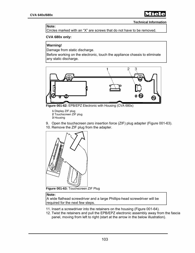
Technical Information
103
CVA 640x/680x
Note: Circles marked with an “X” are screws that do not have to be removed.
CVA 680x only:
Warning! Damage from static discharge. Before working on the electronic, touch the appliance chassis to eliminate any static discharge.
Figure 001-62: EPB/EPZ Electronic with Housing (CVA 680x)
1 Display ZIF plug 2 Touchscreen ZIF plug 3 Housing
9. Open the touchscreen zero insertion force (ZIF) plug adapter (Figure 001-63). 10. Remove the ZIF plug from the adapter.
Figure 001-63: Touchscreen ZIF Plug
Note: A wide flathead screwdriver and a large Phillips-head screwdriver will be required for the next few steps.
11. Insert a screwdriver into the retainers on the housing (Figure 001-64). 12. Twist the retainers and pull the EPB/EPZ electronic assembly away from the fascia
panel, moving from left to right (start at the arrow in the below illustration).

Technical Information
104
CVA 640x/680x
Figure 001-64: Display Electronic Removal, CVA 680x