Cut Charts · 2013-11-12 · 4-10 MAX200 Instruction Manual 15 OPERATION Cut Charts The following...
37
4-10 MAX200 Instruction Manual 15 OPERATION Cut Charts The following Cut Charts provide the necessary information in order for the operator using the MAX200 machine torch system to be successful in plasma arc cutting. The Cut Charts are divided into two areas: (1) above water cutting (pages 4-11 through 4-33) and (2) under water cutting, where the water table water is 3" above the top surface of the workpiece (pages 4-34 through 4-45). The following table provides the operator with a quick reference of the consumables used for all cutting and gouging applications with the MAX200 machine torch. Also listed are the consumables used with the water-muffler. Part Numbers Plasma Gas/ Nozzle Type Retaining Shield Gas (Amps) Shield Cap Nozzle Swirl Ring Electrode Air/Air 200 020424 120837 020608 020607 220021 100 020448 120837 020611 020607 120547 40 020688 020423 020689 020613 220021 200 gouging 020485 020423 020615 020607 220021 O 2 /Air 200 020424 120837 020605 020604 220021 100 020448 120837 020616 020617 120547 H35/N 2 200 020602 120837 020608 020607 020415 100 020448 120837 020611 020607 020415 200 gouging 020485 020423 020615 020607 020415 N 2 /CO 2 200 020424 120837 020608 020607 020415 N 2 /Air 200 020424 120837 020608 020607 020415 Beveling Consumables O 2 /Air 200 beveling 120260 020423 120259 120833 120258 Water Tube 120257 Consumables Used with MAX200 Water-Muffler Air/Air 200 020566 020423 020608 020607 220021 100 020618 020423 020611 020607 120547 O 2 /Air 200 020566 020423 020605 020604 220021 100 020618 020423 020616 020617 120547 N 2 /CO 2 200 020566 020423 020608 020607 020415 N 2 /Air 200 020566 020423 020608 020607 020415 MAX200 Machine Torch Consumables
Transcript of Cut Charts · 2013-11-12 · 4-10 MAX200 Instruction Manual 15 OPERATION Cut Charts The following...
4-10 MAX200 Instruction Manual15
OPERATION
Cut Charts
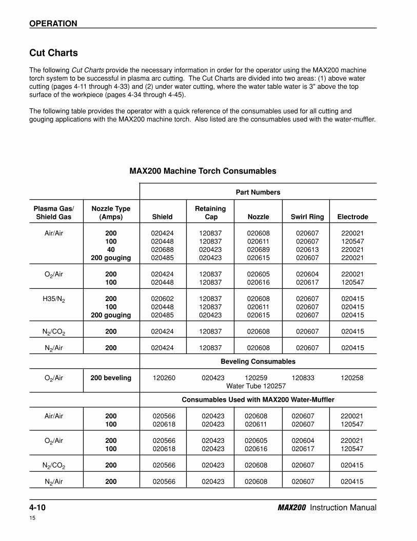
The following Cut Charts provide the necessary information in order for the operator using the MAX200 machinetorch system to be successful in plasma arc cutting. The Cut Charts are divided into two areas: (1) above watercutting (pages 4-11 through 4-33) and (2) under water cutting, where the water table water is 3" above the topsurface of the workpiece (pages 4-34 through 4-45).
The following table provides the operator with a quick reference of the consumables used for all cutting andgouging applications with the MAX200 machine torch. Also listed are the consumables used with the water-muffler.
Part Numbers
Plasma Gas/ Nozzle Type Retaining
Shield Gas (Amps) Shield Cap Nozzle Swirl Ring Electrode
Air/Air 200 020424 120837 020608 020607 220021100 020448 120837 020611 020607 12054740 020688 020423 020689 020613 220021
200 gouging 020485 020423 020615 020607 220021
O2/Air 200 020424 120837 020605 020604 220021100 020448 120837 020616 020617 120547
H35/N2 200 020602 120837 020608 020607 020415100 020448 120837 020611 020607 020415
200 gouging 020485 020423 020615 020607 020415
N2/CO2 200 020424 120837 020608 020607 020415
N2/Air 200 020424 120837 020608 020607 020415
Beveling Consumables
O2/Air 200 beveling 120260 020423 120259 120833 120258Water Tube 120257
Consumables Used with MAX200 Water-Muffler
Air/Air 200 020566 020423 020608 020607 220021100 020618 020423 020611 020607 120547
O2/Air 200 020566 020423 020605 020604 220021100 020618 020423 020616 020617 120547
N2/CO2 200 020566 020423 020608 020607 020415
N2/Air 200 020566 020423 020608 020607 020415
MAX200 Machine Torch Consumables

Shield Gas
PressureMaterial
Thickness
Arc Voltage Setting
Approx. Motion
Delay Time
Test (psi)
Run (psi)
(psi) (Inches) (Inches) (mm) (Volts) (ipm) (mm/min) (sec)
3/16 1/8 3 130 200 5080 0.0
1/4 1/8 3 130 135 3400 0.5
3/8 1/8 3 135 100 2540 1.0
1/2 .16 4 140 80 2030 2.0
5/8 .16 4 145 60 1520 2.0
3/4 3/16 5 150 45 1140 2.5
7/8 1/4 6 155 30 760 2.5
1 1/4 6 160 25 635 2.5
1-1/4 1/4 6 165 15 380 *
1-1/2 1/4 6 170 10 250 *
1-3/4 5/16 8 180 7 180 *
2 5/16 8 185 5 130 *
Shield Gas
PressureMaterial
Thickness
Arc Voltage Setting
Approx. Motion
Delay Time
Test (bar)
Run (bar)
(bar) (mm) (mm) (Inches) (Volts) (mm/min) (ipm) (sec)
6 3 1/8 130 3400 135 0.5
8 3 1/8 135 2900 115 0.5
10 3 1/8 135 2540 100 1.0
12 4 .16 140 2030 80 2.0
15 4 .16 145 1520 60 2.0
20 5 3/16 150 1140 45 2.5
25 6 1/4 160 635 25 2.5
32 6 1/4 165 380 15 *
50 8 5/16 185 130 5 *
60
Plasma Gas Pressure
English
Plasma Gas
Flowrate (SCFH)
Shield Gas
Flowrate (SCFH)
66 44-48 58-62 270
Plasma Gas Pressure Shield
Gas Flowrate (l/min)
Metric
Plasma Gas
Flowrate (l/min)
Torch-to-Work Distance
Torch-to-Work Distance
Travel Speed
Travel Speed
4.031 3.0-3.3 4.0-4.3 127
MAX200 Instruction Manual 4-1114
OPERATION
Mild Steel – Above Water
200 amps • Air Plasma / Air Shield
This gas combination gives good cut speed, low dross levels and is very economical. Some surface
nitriting can occur.
Set plasma gas inlet pressure to 90 psi (6.2 bar)
Set shield gas inlet pressure to 90 psi (6.2 bar)
If leads are greater than 50 feet, increase TEST pressure 5 psi for every extra 50 feet of torch lead length.
* Production cutting above 1 inch (25 mm) not recommended.
020424Shield
020608Nozzle
120837Retaining cap
220021Electrode
020607Swirl ring
4-12 MAX200 Instruction Manual14
OPERATION
Shield Gas
PressureMaterial
Thickness
Arc Voltage Setting
Approx. Motion
Delay Time
Test (psi)
Run (psi)
(psi) (Inches) (Inches) (mm) (Volts) (ipm) (mm/min) (sec)
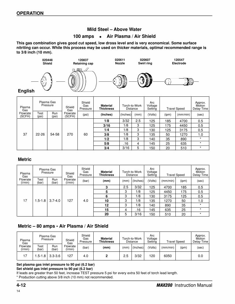
1/8 3/32 2.5 125 185 4700 0.5
3/16 1/8 3 125 175 4450 0.5
1/4 1/8 3 130 125 3175 0.5
3/8 1/8 3 135 50 1270 1.0
1/2 1/8 3 140 35 890 *
5/8 .16 4 145 25 635 *
3/4 3/16 5 150 20 510 *
Shield Gas
PressureMaterial
Thickness
Arc Voltage Setting
Approx. Motion
Delay Time
Test (bar)
Run (bar)
(bar) (mm) (mm) (Inches) (Volts) (mm/min) (ipm) (sec)
3 2.5 3/32 125 4700 185 0.5
5 3 1/8 125 4450 175 0.5
6 3 1/8 130 3175 125 0.5
10 3 1/8 135 1270 50 1.0
12 3 1/8 140 890 35 *
15 4 .16 145 635 25 *
20 5 3/16 150 510 20 *
Metric – 80 amps • Air Plasma / Air Shield
Shield Gas
PressureMaterial
Thickness
Arc Voltage Setting
Approx. Motion
Delay Time
Test (bar)
Run (bar)
(bar) (mm) (mm) (Inches) (Volts) (mm/min) (ipm) (sec)
17 1.5-1.8 3.3-3.6 127 4.0 2 2.5 3/32 120 6050 0.0
Plasma Gas
Flowrate (l/min)
Plasma Gas Pressure Shield
Gas Flowrate (l/min)
Metric
Plasma Gas
Flowrate (l/min)
Plasma Gas Pressure Shield
Gas Flowrate (l/min)
17 1.5-1.8 127 4.03.7-4.0
270
English
Plasma Gas
Flowrate (SCFH)
Plasma Gas Pressure
Shield Gas
Flowrate (SCFH)
37 22-26 54-58
Torch-to-Work Distance
60
Torch-to-Work Distance
Torch-to-Work Distance
Travel Speed
Travel Speed
Travel Speed
Mild Steel – Above Water
100 amps • Air Plasma / Air Shield
This gas combination gives good cut speed, low dross level and is very economical. Some surface
nitriting can occur. While this process may be used on thicker materials, optimal recommended range is
to 3/8 inch (10 mm).
Set plasma gas inlet pressure to 90 psi (6.2 bar)
Set shield gas inlet pressure to 90 psi (6.2 bar)
If leads are greater than 50 feet, increase TEST pressure 5 psi for every extra 50 feet of torch lead length.
* Production cutting above 3/8 inch (10 mm) not recommended.
020448Shield
020611Nozzle
120837Retaining cap
120547Electrode
020607Swirl ring

MAX200 Instruction Manual 4-1315
OPERATION
Shield Gas
PressureMaterial
Thickness
Arc Voltage Setting
Approx. Motion
Delay Time
Test (psi)
Run (psi)
(psi) (Inches) (Inches) (mm) (Volts) (ipm) (mm/min) (sec)
.050 (18GA.) 3/32 2.5 110 320 8100 0.0
1/16 3/32 2.5 110 300 7600 0.0
.075 3/32 2.5 110 220 5600 0.0
1/8 3/32 2.5 110 140 3550 0.5
.158 3/32 2.5 115 120 3050 *
.197 3/32 2.5 115 50 1250 *
1/4 3/32 2.5 120 35 850 *
3/8 3/32 2.5 125 20 500 *
Shield Gas
PressureMaterial
Thickness
Arc Voltage Setting
Approx. Motion
Delay Time
Test (bar)
Run (bar)
(bar) (mm) (mm) (Inches) (Volts) (mm/min) (ipm) (sec)
2 2.5 3/32 110 5600 220 0.0
3 2.5 3/32 110 3550 140 0.5
4 2.5 3/32 115 3050 120 *
5 2.5 3/32 115 1250 50 *
6 2.5 3/32 120 850 35 *
10 2.5 3/32 125 500 20 *
Travel Speed
Travel Speed
Torch-to-Work Distance
Torch-to-Work Distance
Shield Gas
Flowrate (SCFH)
Plasma Gas Pressure
Plasma Gas
Flowrate (SCFH)
English
Metric
Plasma Gas
Flowrate (l/min)
Plasma Gas Pressure Shield
Gas Flowrate (l/min)
4.0
25 16-20 56-60 275 60
12 1.1-1.4 3.9-4.1 129
Mild Steel – Above Water
40 amps • Air Plasma / Air Shield
This gas combination gives good cut speeds, low dross levels and is very economical. Some surface
nitriting can occur.
Set plasma gas inlet pressure to 90 psi (6.2 bar)
Set shield gas inlet pressure to 90 psi (6.2 bar)
If leads are greater than 50 feet, increase TEST pressure 5 psi for every extra 50 feet of torch lead length.
* Production cutting above 1/8 inch (3 mm) not recommended.
020514Shield
020689Nozzle
020423Retaining cap
120547Electrode
020613Swirl ring
4-14 MAX200 Instruction Manual15
OPERATION
Shield Gas
PressureMaterial
Thickness
Arc Voltage Setting
Approx. Motion
Delay Time
Test (psi)
Run (psi)
(psi) (Inches) (Inches) (mm) (Volts) (ipm) (mm/min) (sec)
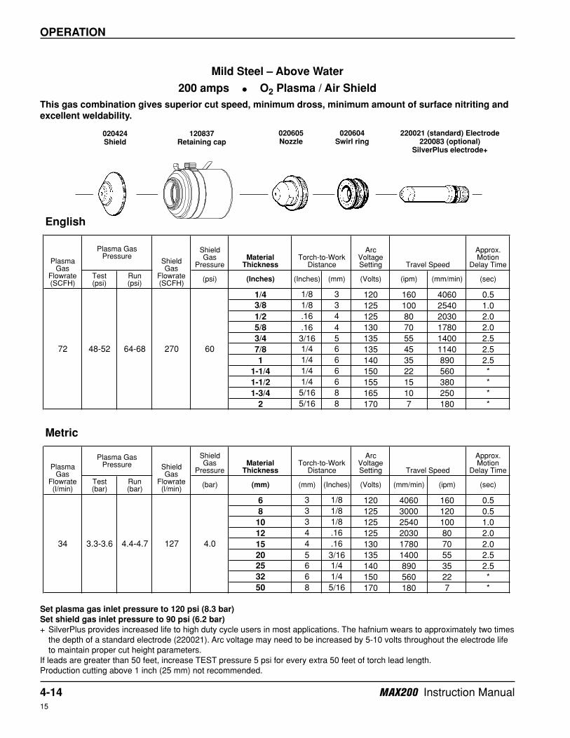
1/4 1/8 3 120 160 4060 0.5
3/8 1/8 3 125 100 2540 1.0
1/2 .16 4 125 80 2030 2.0
5/8 .16 4 130 70 1780 2.0
3/4 3/16 5 135 55 1400 2.5
7/8 1/4 6 135 45 1140 2.5
1 1/4 6 140 35 890 2.5
1-1/4 1/4 6 150 22 560 *
1-1/2 1/4 6 155 15 380 *
1-3/4 5/16 8 165 10 250 *
2 5/16 8 170 7 180 *
Shield Gas
PressureMaterial
Thickness
Arc Voltage Setting
Approx. Motion
Delay Time
Test (bar)
Run (bar)
(bar) (mm) (mm) (Inches) (Volts) (mm/min) (ipm) (sec)
6 3 1/8 120 4060 160 0.5
8 3 1/8 125 3000 120 0.5
10 3 1/8 125 2540 100 1.0
12 4 .16 125 2030 80 2.0
15 4 .16 130 1780 70 2.0
20 5 3/16 135 1400 55 2.5
25 6 1/4 140 890 35 2.5
32 6 1/4 150 560 22 *
50 8 5/16 170 180 7 *
4.0
60
Metric
Plasma Gas
Flowrate (l/min)
Plasma Gas Pressure Shield
Gas Flowrate (l/min)
72 48-52 64-68 270
34 3.3-3.6 4.4-4.7 127
English
Plasma Gas
Flowrate (SCFH)
Plasma Gas Pressure
Shield Gas
Flowrate (SCFH)
Torch-to-Work Distance
Torch-to-Work Distance
Travel Speed
Travel Speed
Mild Steel – Above Water
200 amps • O2 Plasma / Air Shield
This gas combination gives superior cut speed, minimum dross, minimum amount of surface nitriting and
excellent weldability.
Set plasma gas inlet pressure to 120 psi (8.3 bar)
Set shield gas inlet pressure to 90 psi (6.2 bar)
+ SilverPlus provides increased life to high duty cycle users in most applications. The hafnium wears to approximately two times
the depth of a standard electrode (220021). Arc voltage may need to be increased by 5-10 volts throughout the electrode life
to maintain proper cut height parameters.
If leads are greater than 50 feet, increase TEST pressure 5 psi for every extra 50 feet of torch lead length.
Production cutting above 1 inch (25 mm) not recommended.
020424Shield
020605Nozzle
120837Retaining cap
220021 (standard) Electrode220083 (optional)
SilverPlus electrode+
020604Swirl ring
MAX200 Instruction Manual 4-1514
OPERATION
Shield Gas
PressureMaterial
Thickness
Arc Voltage Setting
Approx. Motion
Delay Time
Test (psi)
Run (psi)
(psi) (Inches) (Inches) (mm) (Volts) (ipm) (mm/min) (sec)
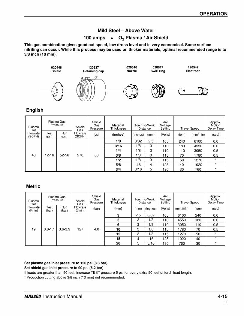
1/8 3/32 2.5 105 240 6100 0.0
3/16 1/8 3 110 180 4550 0.0
1/4 1/8 3 110 110 3050 0.5
3/8 1/8 3 115 70 1780 0.5
1/2 1/8 3 115 50 1270 *
5/8 .16 4 125 40 1020 *
3/4 3/16 5 130 30 760 *
Shield Gas
PressureMaterial
Thickness
Arc Voltage Setting
Approx. Motion
Delay Time
Test (bar)
Run (bar)
(bar) (mm) (mm) (Inches) (Volts) (mm/min) (ipm) (sec)
3 2.5 3/32 105 6100 240 0.0
5 3 1/8 110 4550 180 0.0
6 3 1/8 110 3050 110 0.5
10 3 1/8 115 1780 70 0.5
12 3 1/8 115 1270 50 *
15 4 .16 125 1020 40 *
20 5 3/16 130 760 30 *
Torch-to-Work Distance Travel Speed
19 0.8-1.1 3.6-3.9 127 4.0
English
Plasma Gas
Flowrate (SCFH)
Plasma Gas Pressure
Shield Gas
Flowrate (SCFH)
Torch-to-Work Distance Travel Speed
40 12-16 52-56 270 60
Metric
Plasma Gas
Flowrate (l/min)
Plasma Gas Pressure Shield
Gas Flowrate (l/min)
Mild Steel – Above Water
100 amps • O2 Plasma / Air Shield
This gas combination gives good cut speed, low dross level and is very economical. Some surface
nitriting can occur. While this process may be used on thicker materials, optimal recommended range is to
3/8 inch (10 mm).
Set plasma gas inlet pressure to 120 psi (8.3 bar)
Set shield gas inlet pressure to 90 psi (6.2 bar)
If leads are greater than 50 feet, increase TEST pressure 5 psi for every extra 50 feet of torch lead length.
* Production cutting above 3/8 inch (10 mm) not recommended.
020448Shield
020616Nozzle
120837Retaining cap
120547Electrode
020617Swirl ring
4-16 MAX200 Instruction Manual14
OPERATION
Shield Gas
PressureMaterial
Thickness
Arc Voltage Setting
Approx. Motion
Delay Time
Test (psi)
Run (psi)
(psi) (Inches) (Inches) (mm) (Volts) (ipm) (mm/min) (sec)
3/16 1/8 3 120 130 3300 0.5
1/4 1/8 3 125 110 2800 1.0
3/8 1/8 3 130 85 2160 1.5
1/2 1/8 3 130 55 1400 2.0
5/8 .16 4 135 45 1140 2.0
3/4 3/16 5 145 25 635 2.5
7/8 1/4 6 150 20 510 3.0
1 1/4 6 160 15 380 3.0
1-1/4 1/4 6 165 10 250 *
1-1/2 1/4 6 175 5 130 *
Shield Gas
PressureMaterial
Thickness
Arc Voltage Setting
Approx. Motion
Delay Time
Test (bar)
Run (bar)
(bar) (mm) (mm) (Inches) (Volts) (mm/min) (ipm) (sec)
5 3 1/8 120 3300 130 0.5
6 3 1/8 125 2800 110 1.0
10 3 1/8 130 2160 85 1.5
12 3 .16 130 1400 55 2.0
15 4 .16 135 1140 45 2.0
20 5 3/16 145 635 25 2.5
25 6 1/4 160 380 15 3.0
32 6 1/4 165 250 10 *
4.0
Plasma Gas
Flowrate (l/min)
Plasma Gas Pressure Shield
Gas Flowrate (l/min)
210
28 2.5-2.8 3.6-3.9 99
60
Metric
36-40 52-56
English
Plasma Gas
Flowrate (SCFH)
Plasma Gas Pressure
Shield Gas
Flowrate (SCFH)
Torch-to-Work Distance Travel Speed
Travel Speed
60
Torch-to-Work Distance
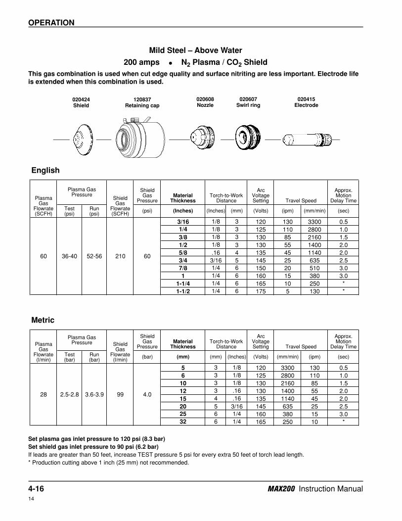
Mild Steel – Above Water
200 amps • N2 Plasma / CO2 Shield
This gas combination is used when cut edge quality and surface nitriting are less important. Electrode life
is extended when this combination is used.
Set plasma gas inlet pressure to 120 psi (8.3 bar)
Set shield gas inlet pressure to 90 psi (6.2 bar)
If leads are greater than 50 feet, increase TEST pressure 5 psi for every extra 50 feet of torch lead length.
* Production cutting above 1 inch (25 mm) not recommended.
020424Shield
020608Nozzle
120837Retaining cap
020415Electrode
020607Swirl ring
MAX200 Instruction Manual 4-1714
OPERATION
Shield Gas
PressureMaterial
Thickness
Arc Voltage Setting
Approx. Motion
Delay Time
Test (psi)
Run (psi)
(psi) (Inches) (Inches) (mm) (Volts) (ipm) (mm/min) (sec)
3/16 1/8 3 125 220 5600 0.0
1/4 1/8 3 130 195 5000 0.5
3/8 1/8 3 130 145 3700 1.0
1/2 1/8 3 135 105 2700 2.0
5/8 .16 4 140 75 1900 2.0
3/4 3/16 5 140 55 1400 2.5
7/8 1/4 6 145 40 1000 3.0
1 1/4 6 150 30 760 *
1-1/4 1/4 6 160 15 380 *
1-1/2 1/4 6 170 10 250 *
Shield Gas
PressureMaterial
Thickness
Arc Voltage Setting
Approx. Motion
Delay Time
Test (bar)
Run (bar)
(bar) (mm) (mm) (Inches) (Volts) (mm/min) (ipm) (sec)
5 3 1/8 125 5600 220 0.0
6 3 1/8 130 5000 195 0.5
10 3 1/8 130 3700 145 1.0
12 3 .16 135 2700 105 2.0
15 4 .16 140 1900 75 2.0
20 5 3/16 140 1400 55 2.5
25 6 1/4 150 760 30 *
32 6 1/4 160 380 15 *
Metric
Plasma Gas
Flowrate (l/min)
Plasma Gas Pressure Shield
Gas Flowrate (l/min)
Torch-to-Work Distance Travel Speed
66 44-48 58-62 270 60
English
Plasma Gas
Flowrate (SCFH)
Plasma Gas Pressure
Shield Gas
Flowrate (SCFH)
Torch-to-Work Distance Travel Speed
31 3.0-3.3 4.0-4.3 127 4.0
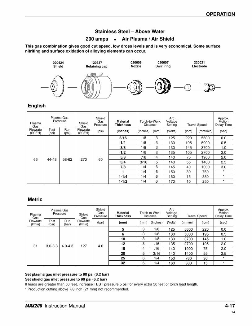
Stainless Steel – Above Water
200 amps • Air Plasma / Air Shield
This gas combination gives good cut speed, low dross levels and is very economical. Some surface
nitriting and surface oxidation of alloying elements can occur.
Set plasma gas inlet pressure to 90 psi (6.2 bar)
Set shield gas inlet pressure to 90 psi (6.2 bar)
If leads are greater than 50 feet, increase TEST pressure 5 psi for every extra 50 feet of torch lead length.
* Production cutting above 7/8 inch (21 mm) not recommended.
020424Shield
020608Nozzle
120837Retaining cap
220021Electrode
020607Swirl ring
4-18 MAX200 Instruction Manual14
OPERATION
Shield Gas
PressureMaterial
Thickness
Arc Voltage Setting
Approx. Motion
Delay Time
Test (psi)
Run (psi)
(psi) (Inches) (Inches) (mm) (Volts) (ipm) (mm/min) (sec)
1/8 3/32 2.5 125 140 3560 0.0
3/16 1/8 3 130 110 2800 0.5
1/4 1/8 3 130 80 2030 0.5
3/8 1/8 3 135 55 1400 0.5
1/2 1/8 3 140 35 890 *
5/8 .16 4 145 25 635 *
3/4 3/16 5 150 20 510 *
Shield Gas
PressureMaterial
Thickness
Arc Voltage Setting
Approx. Motion
Delay Time
Test (bar)
Run (bar)
(bar) (mm) (mm) (Inches) (Volts) (mm/min) (ipm) (sec)
3 2.5 3/32 125 3560 140 0.0
5 3 1/8 130 2800 110 0.5
6 3 1/8 130 2030 80 0.5
10 3 1/8 135 1400 55 0.5
12 3 1/8 140 890 35 *
15 4 .16 145 635 25 *
20 5 3/16 150 510 20 *
Metric
Plasma Gas
Flowrate (l/min)
Plasma Gas Pressure Shield
Gas Flowrate (l/min)
Torch-to-Work Distance Travel Speed
37 22-26 54-58 270 60
English
Plasma Gas
Flowrate (SCFH)
Plasma Gas Pressure
Shield Gas
Flowrate (SCFH)
Torch-to-Work Distance Travel Speed
17 1.5-1.8 3.7-4.0 127 4.0
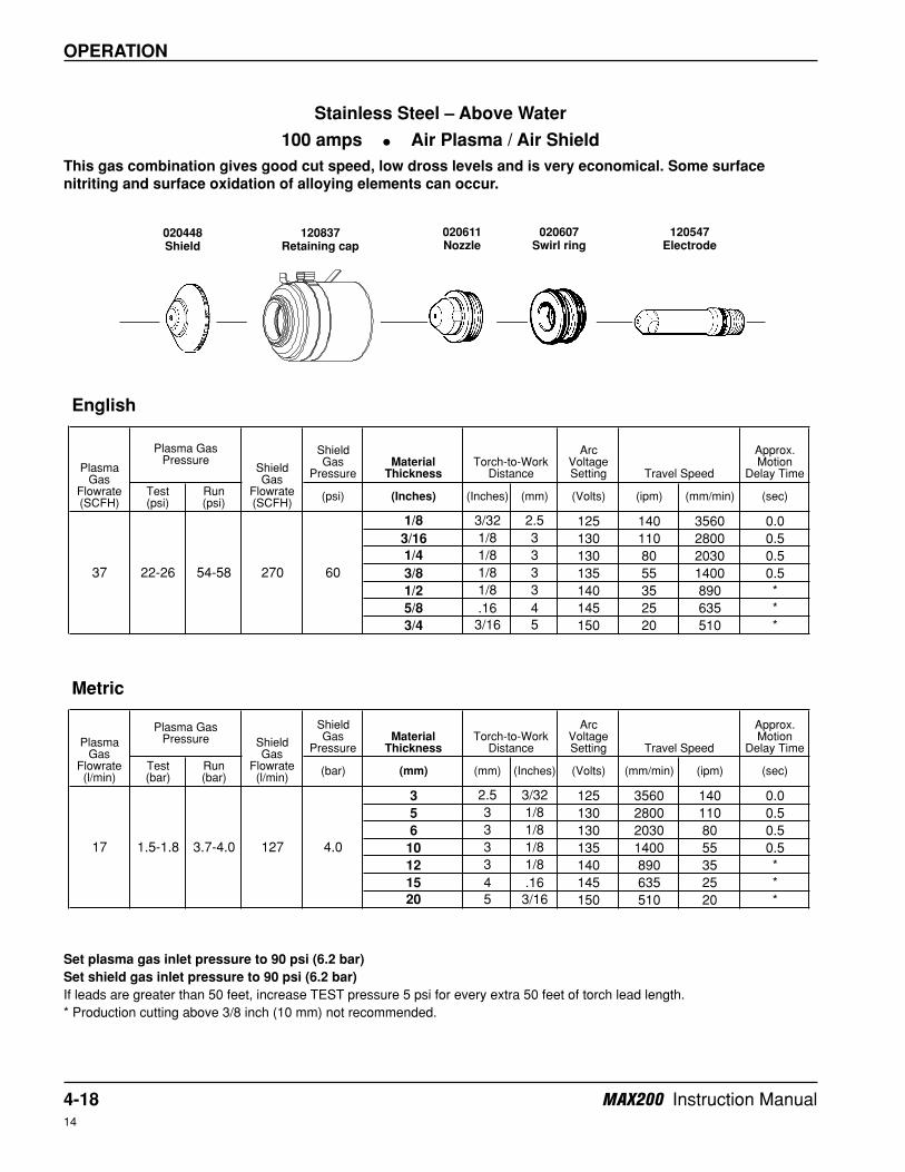
Stainless Steel – Above Water
100 amps • Air Plasma / Air Shield
This gas combination gives good cut speed, low dross levels and is very economical. Some surface
nitriting and surface oxidation of alloying elements can occur.
Set plasma gas inlet pressure to 90 psi (6.2 bar)
Set shield gas inlet pressure to 90 psi (6.2 bar)
If leads are greater than 50 feet, increase TEST pressure 5 psi for every extra 50 feet of torch lead length.
* Production cutting above 3/8 inch (10 mm) not recommended.
020448Shield
020611Nozzle
120837Retaining cap
120547Electrode
020607Swirl ring
MAX200 Instruction Manual 4-1915
OPERATION
Shield Gas
PressureMaterial
Thickness
Arc Voltage Setting
Approx. Motion
Delay Time
Test (psi)
Run (psi)
(psi) (Inches) (Inches) (mm) (Volts) (ipm) (mm/min) (sec)
.050 (18GA.) 3/32 2.5 120 145 3700 0.0
1/16 3/32 2.5 120 120 3050 0.0
1/8 3/32 2.5 125 75 1900 0.5
1/4 1/8 3 135 30 750 *
3/8 1/8 3 140 12 300 *
Shield Gas
PressureMaterial
Thickness
Arc Voltage Setting
Approx. Motion
Delay Time
Test (bar)
Run (bar)
(bar) (mm) (mm) (Inches) (Volts) (mm/min) (ipm) (sec)
3 2.5 3/32 125 1900 75 0.5
6 3 1/8 135 750 30 *
10 3 1/8 140 300 12 *
Torch-to-Work Distance Travel Speed
English
Plasma Gas
Flowrate (SCFH)
Plasma Gas Pressure
Shield Gas
Flowrate (SCFH)
Torch-to-Work Distance Travel Speed
Metric
Plasma Gas
Flowrate (l/min)
Plasma Gas Pressure Shield
Gas Flowrate (l/min)
4.0
25 16-20 56-60 275 60
12 1.1-1.4 3.9-4.1 129
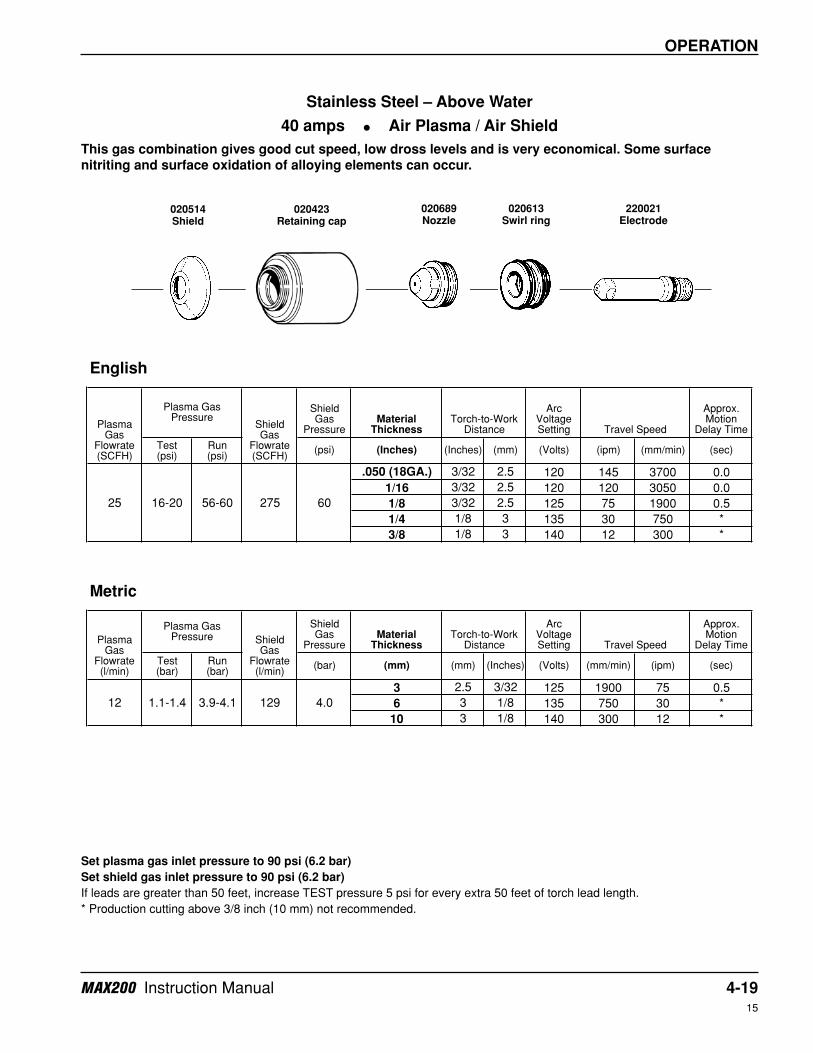
Stainless Steel – Above Water
40 amps • Air Plasma / Air Shield
This gas combination gives good cut speed, low dross levels and is very economical. Some surface
nitriting and surface oxidation of alloying elements can occur.
Set plasma gas inlet pressure to 90 psi (6.2 bar)
Set shield gas inlet pressure to 90 psi (6.2 bar)
If leads are greater than 50 feet, increase TEST pressure 5 psi for every extra 50 feet of torch lead length.
* Production cutting above 3/8 inch (10 mm) not recommended.
020514Shield
020689Nozzle
020423Retaining cap
220021Electrode
020613Swirl ring
4-20 MAX200 Instruction Manual14
OPERATION
Shield Gas
PressureMaterial
Thickness
Arc Voltage Setting
Approx. Motion
Delay Time
Test (psi)
Run (psi)
(psi) (Inches) (Inches) (mm) (Volts) (ipm) (mm/min) (sec)
3/16 1/8 3 125 135 3430 0.0
1/4 1/8 3 130 120 3050 0.5
3/8 1/8 3 130 100 2540 1.0
1/2 1/8 3 135 75 1900 2.0
5/8 .16 4 140 60 1520 2.0
3/4 3/16 5 140 45 1140 2.5
7/8 1/4 6 145 35 890 2.5
1 1/4 6 150 20 510 *
1-1/4 1/4 6 160 15 380 *
1-1/2 1/4 6 160 10 250 *
Shield Gas
PressureMaterial
Thickness
Arc Voltage Setting
Approx. Motion
Delay Time
Test (bar)
Run (bar)
(bar) (mm) (mm) (Inches) (Volts) (mm/min) (ipm) (sec)
5 3 1/8 125 3430 135 0.0
6 3 1/8 130 3050 120 0.5
10 3 1/8 130 2540 100 1.0
12 3 .16 135 1900 75 2.0
15 4 .16 140 1520 60 2.0
20 5 3/16 140 1140 45 2.5
25 6 1/4 150 510 20 *
32 6 1/4 160 380 15 *
English
Plasma Gas
Flowrate (SCFH)
Plasma Gas Pressure
Shield Gas
Flowrate (SCFH)
Torch-to-Work Distance Travel Speed
60 34-38 50-54 270 60
Metric
Plasma Gas
Flowrate (l/min)
Plasma Gas Pressure Shield
Gas Flowrate (l/min)
Torch-to-Work Distance Travel Speed
28 2.3-2.6 3.4-3.7 127 4.0
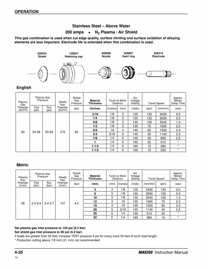
Stainless Steel – Above Water
200 amps • N2 Plasma / Air Shield
This gas combination is used when cut edge quality, surface nitriting and surface oxidation of alloying
elements are less important. Electrode life is extended when this combination is used.
Set plasma gas inlet pressure to 120 psi (8.3 bar)
Set shield gas inlet pressure to 90 psi (6.2 bar)
If leads are greater than 50 feet, increase TEST pressure 5 psi for every extra 50 feet of torch lead length.
* Production cutting above 7/8 inch (21 mm) not recommended.
020424Shield
020608Nozzle
120837Retaining cap
020415Electrode
020607Swirl ring

MAX200 Instruction Manual 4-2114
OPERATION
Shield Gas
PressureMaterial
Thickness
Arc Voltage Setting
Approx. Motion
Delay Time
Test (psi)
Run (psi)
(psi) (Inches) (Inches) (mm) (Volts) (ipm) (mm/min) (sec)
3/16 1/8 3 125 190 4800 0.5
1/4 1/8 3 130 170 4300 1.0
3/8 1/8 3 130 125 3200 1.5
1/2 1/8 3 135 95 2400 2.0
5/8 .16 4 140 70 1800 2.0
3/4 3/16 5 140 50 1250 2.5
7/8 1/4 6 145 40 1000 3.0
1 1/4 6 150 30 760 *
1-1/4 1/4 6 160 15 380 *
1-1/2 1/4 6 170 10 250 *
Shield Gas
PressureMaterial
Thickness
Arc Voltage Setting
Approx. Motion
Delay Time
Test (bar)
Run (bar)
(bar) (mm) (mm) (Inches) (Volts) (mm/min) (ipm) (sec)
5 3 1/8 125 4800 190 0.5
6 3 1/8 130 4300 170 1.0
10 3 1/8 130 3200 125 1.5
12 3 .16 135 2400 95 2.0
15 4 .16 140 1800 70 2.0
20 5 3/16 140 1250 50 2.5
25 6 1/4 150 760 30 *
32 6 1/4 160 380 15 *
English
Plasma Gas
Flowrate (SCFH)
Plasma Gas Pressure
Shield Gas
Flowrate (SCFH)
Torch-to-Work Distance Travel Speed
60 36-40 52-56 210 60
Metric
Plasma Gas
Flowrate (l/min)
Plasma Gas Pressure Shield
Gas Flowrate (l/min)
Torch-to-Work Distance Travel Speed
28 2.5-2.8 3.6-3.9 99 4.0
Stainless Steel – Above Water
200 amps • N2 Plasma / CO2 Shield
This gas combination is used when surface nitriting and surface oxidation of alloying elements is less
important. Electrode life is extended when using this gas combination.
Set plasma gas inlet pressure to 120 psi (8.3 bar)
Set shield gas inlet pressure to 90 psi (6.2 bar)
If leads are greater than 50 feet, increase TEST pressure 5 psi for every extra 50 feet of torch lead length.
* Production cutting above 7/8 inch (21 mm) not recommended.
020424Shield
020608Nozzle
120837Retaining cap
020415Electrode
020607Swirl ring
4-22 MAX200 Instruction Manual14
OPERATION
Shield Gas
PressureMaterial
Thickness
Arc Voltage Setting
Approx. Motion
Delay Time
Test (psi)
Run (psi)
(psi) (Inches) (Inches) (mm) (Volts) (ipm) (mm/min) (sec)
1/4 3/16 5 135 62 1600 1.0
3/8 3/16 5 140 52 1300 1.0
1/2 3/16 5 140 42 1100 2.0
5/8 1/4 6 145 37 940 2.0
3/4 1/4 6 150 32 810 2.5
7/8 5/16 8 155 27 690 2.5
1 5/16 8 155 22 560 *
1-1/4 5/16 8 165 16 400 *
1-1/2 5/16 8 170 11 280 *
1-3/4 5/16 8 180 8 200 *
2 5/16 8 185 6 150 *
Shield Gas
PressureMaterial
Thickness
Arc Voltage Setting
Approx. Motion
Delay Time
Test (bar)
Run (bar)
(bar) (mm) (mm) (Inches) (Volts) (mm/min) (ipm) (sec)
6 5 3/16 135 1600 62 1.0
10 5 3/16 140 1300 52 1.0
12 5 3/16 140 1100 42 2.0
15 6 1/4 145 940 37 2.0
20 6 1/4 150 810 32 2.5
25 8 5/16 155 560 22 *
32 8 5/16 165 400 16 *
English
Plasma Gas
Flowrate (SCFH)
Plasma Gas Pressure
Shield Gas
Flowrate (SCFH)
Torch-to-Work Distance Travel Speed
70 36-40 62-66 275 60
Torch-to-Work Distance Travel Speed
Metric
Plasma Gas
Flowrate (l/min)
Plasma Gas Pressure Shield
Gas Flowrate (l/min)
4.033 2.5-2.8 4.3-4.5 129
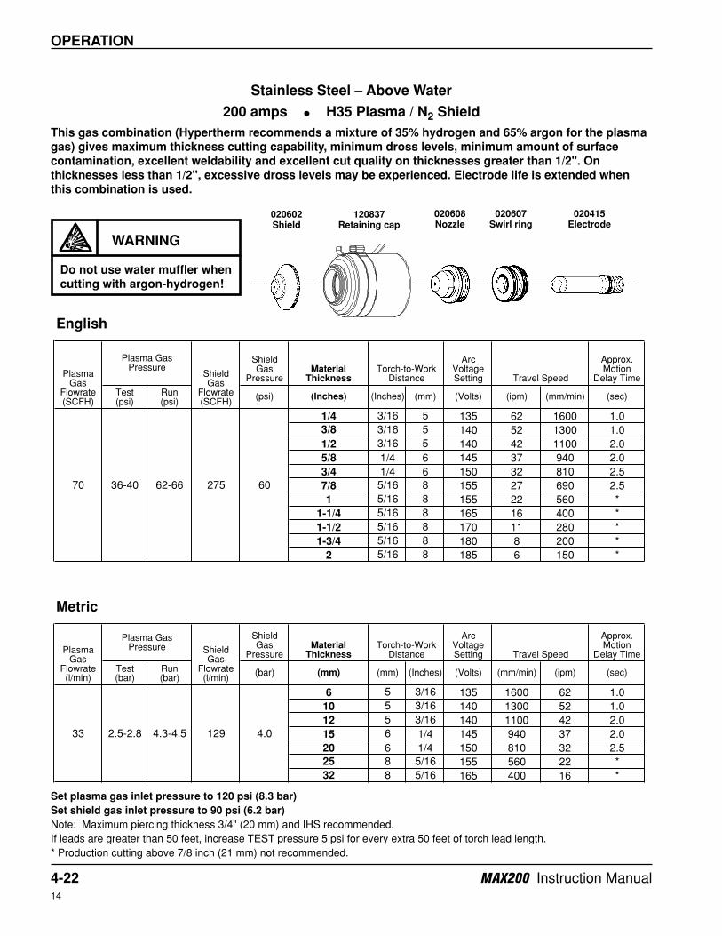
Stainless Steel – Above Water
200 amps • H35 Plasma / N2 Shield
This gas combination (Hypertherm recommends a mixture of 35% hydrogen and 65% argon for the plasma
gas) gives maximum thickness cutting capability, minimum dross levels, minimum amount of surface
contamination, excellent weldability and excellent cut quality on thicknesses greater than 1/2". On
thicknesses less than 1/2", excessive dross levels may be experienced. Electrode life is extended when
this combination is used.
Set plasma gas inlet pressure to 120 psi (8.3 bar)
Set shield gas inlet pressure to 90 psi (6.2 bar)
Note: Maximum piercing thickness 3/4" (20 mm) and IHS recommended.
If leads are greater than 50 feet, increase TEST pressure 5 psi for every extra 50 feet of torch lead length.
* Production cutting above 7/8 inch (21 mm) not recommended.
WARNING
Do not use water muffler when
cutting with argon-hydrogen!
020602Shield
020608Nozzle
120837Retaining cap
020415Electrode
020607Swirl ring
MAX200 Instruction Manual 4-2314
OPERATION
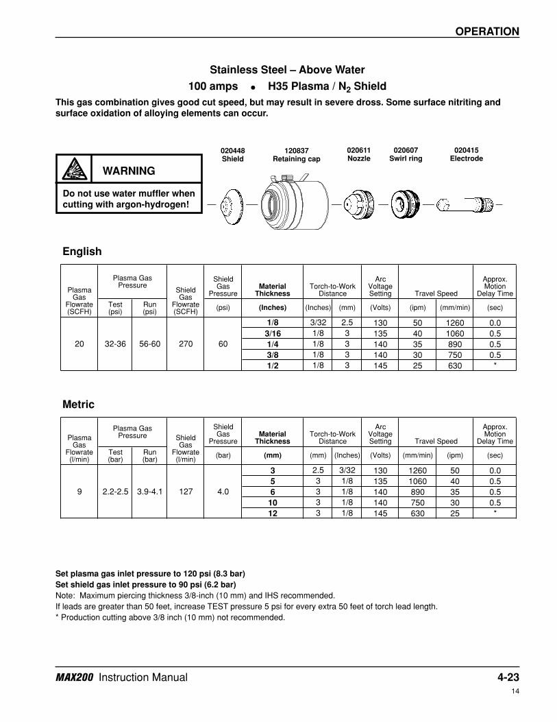
Set plasma gas inlet pressure to 120 psi (8.3 bar)
Set shield gas inlet pressure to 90 psi (6.2 bar)
Note: Maximum piercing thickness 3/8-inch (10 mm) and IHS recommended.
If leads are greater than 50 feet, increase TEST pressure 5 psi for every extra 50 feet of torch lead length.
* Production cutting above 3/8 inch (10 mm) not recommended.
Shield Gas
PressureMaterial
Thickness
Arc Voltage Setting
Approx. Motion
Delay Time
Test (psi)
Run (psi)
(psi) (Inches) (Inches) (mm) (Volts) (ipm) (mm/min) (sec)
1/8 3/32 2.5 130 50 1260 0.0
3/16 1/8 3 135 40 1060 0.5
1/4 1/8 3 140 35 890 0.5
3/8 1/8 3 140 30 750 0.5
1/2 1/8 3 145 25 630 *
Shield Gas
PressureMaterial
Thickness
Arc Voltage Setting
Approx. Motion
Delay Time
Test (bar)
Run (bar)
(bar) (mm) (mm) (Inches) (Volts) (mm/min) (ipm) (sec)
3 2.5 3/32 130 1260 50 0.0
5 3 1/8 135 1060 40 0.5
6 3 1/8 140 890 35 0.5
10 3 1/8 140 750 30 0.5
12 3 1/8 145 630 25 *
English
Plasma Gas
Flowrate (SCFH)
Plasma Gas Pressure
Shield Gas
Flowrate (SCFH)
Torch-to-Work Distance Travel Speed
20 32-36 56-60 270 60
Torch-to-Work Distance Travel Speed
Metric
Plasma Gas
Flowrate (l/min)
Plasma Gas Pressure Shield
Gas Flowrate (l/min)
4.09 2.2-2.5 3.9-4.1 127
Stainless Steel – Above Water
100 amps • H35 Plasma / N2 Shield
This gas combination gives good cut speed, but may result in severe dross. Some surface nitriting and
surface oxidation of alloying elements can occur.
WARNING
Do not use water muffler whencutting with argon-hydrogen!
020448Shield
020611Nozzle
120837Retaining cap
020415Electrode
020607Swirl ring
4-24 MAX200 Instruction Manual14
OPERATION
Shield Gas
PressureMaterial
Thickness
Arc Voltage Setting
Approx. Motion
Delay Time
Test (psi)
Run (psi)
(psi) (Inches) (Inches) (mm) (Volts) (ipm) (mm/min) (sec)
3/16 1/8 3 130 220 5600 0.5
1/4 1/8 3 140 190 4800 1.0
3/8 1/8 3 140 145 3700 2.0
1/2 1/8 3 145 110 2800 2.5
5/8 .16 4 150 85 2200 2.5
3/4 3/16 5 155 65 1650 2.5
7/8 1/4 6 160 50 1300 2.5
1 1/4 6 165 35 900 *
1-1/4 1/4 6 170 20 500 *
1-1/2 1/4 6 175 12 300 *
Shield Gas
PressureMaterial
Thickness
Arc Voltage Setting
Approx. Motion
Delay Time
Test (bar)
Run (bar)
(bar) (mm) (mm) (Inches) (Volts) (mm/min) (ipm) (sec)
5 3 1/8 130 5600 220 0.5
6 3 1/8 140 4800 190 1.0
10 3 1/8 140 3700 145 2.0
12 3 .16 145 2800 110 2.5
15 4 .16 150 2200 85 2.5
20 5 3/16 155 1650 65 2.5
25 6 1/4 165 900 35 *
32 6 1/4 170 500 20 *
English
Plasma Gas
Flowrate (SCFH)
Plasma Gas Pressure
Shield Gas
Flowrate (SCFH)
Torch-to-Work Distance Travel Speed
66 44-48 58-62 270 60
Metric
Plasma Gas
Flowrate (l/min)
Plasma Gas Pressure Shield
Gas Flowrate (l/min)
Torch-to-Work Distance Travel Speed
31 3.0-3.3 4.0-4.3 127 4.0
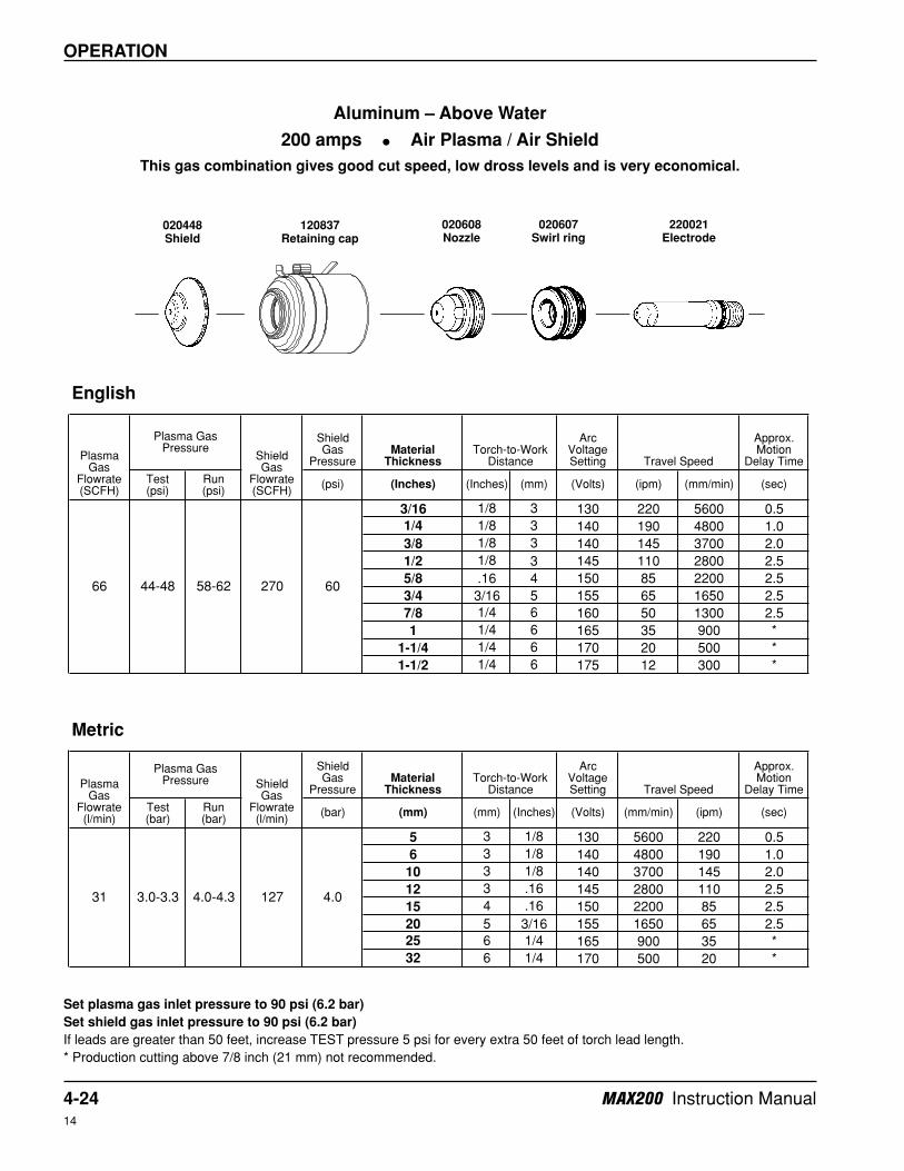
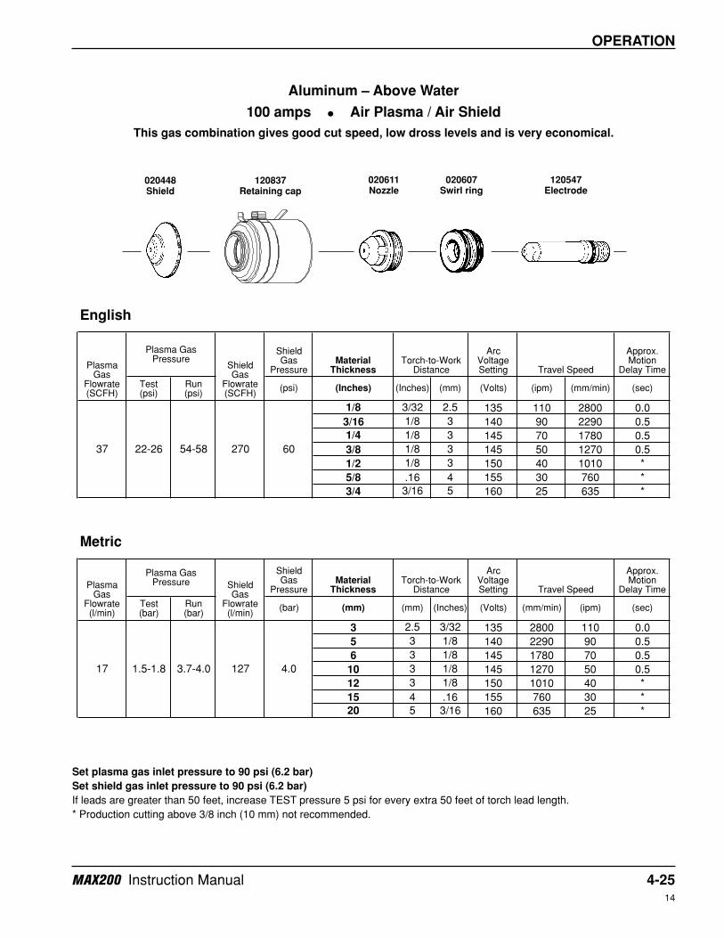
Aluminum – Above Water
200 amps • Air Plasma / Air Shield
This gas combination gives good cut speed, low dross levels and is very economical.
Set plasma gas inlet pressure to 90 psi (6.2 bar)
Set shield gas inlet pressure to 90 psi (6.2 bar)
If leads are greater than 50 feet, increase TEST pressure 5 psi for every extra 50 feet of torch lead length.
* Production cutting above 7/8 inch (21 mm) not recommended.
020448Shield
020608Nozzle
120837Retaining cap
220021Electrode
020607Swirl ring
MAX200 Instruction Manual 4-2514
OPERATION
Shield Gas
PressureMaterial
Thickness
Arc Voltage Setting
Approx. Motion
Delay Time
Test (psi)
Run (psi)
(psi) (Inches) (Inches) (mm) (Volts) (ipm) (mm/min) (sec)
1/8 3/32 2.5 135 110 2800 0.0
3/16 1/8 3 140 90 2290 0.5
1/4 1/8 3 145 70 1780 0.5
3/8 1/8 3 145 50 1270 0.5
1/2 1/8 3 150 40 1010 *
5/8 .16 4 155 30 760 *
3/4 3/16 5 160 25 635 *
Shield Gas
PressureMaterial
Thickness
Arc Voltage Setting
Approx. Motion
Delay Time
Test (bar)
Run (bar)
(bar) (mm) (mm) (Inches) (Volts) (mm/min) (ipm) (sec)
3 2.5 3/32 135 2800 110 0.0
5 3 1/8 140 2290 90 0.5
6 3 1/8 145 1780 70 0.5
10 3 1/8 145 1270 50 0.5
12 3 1/8 150 1010 40 *
15 4 .16 155 760 30 *
20 5 3/16 160 635 25 *
English
Plasma Gas
Flowrate (SCFH)
Plasma Gas Pressure
Shield Gas
Flowrate (SCFH)
Torch-to-Work Distance Travel Speed
37 22-26 54-58 270 60
Metric
Plasma Gas
Flowrate (l/min)
Plasma Gas Pressure Shield
Gas Flowrate (l/min)
Torch-to-Work Distance Travel Speed
17 1.5-1.8 3.7-4.0 127 4.0
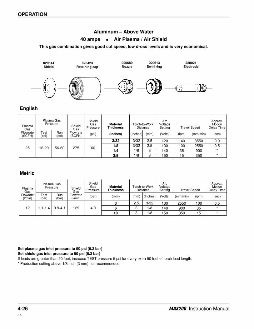
Aluminum – Above Water
100 amps • Air Plasma / Air Shield
This gas combination gives good cut speed, low dross levels and is very economical.
Set plasma gas inlet pressure to 90 psi (6.2 bar)
Set shield gas inlet pressure to 90 psi (6.2 bar)
If leads are greater than 50 feet, increase TEST pressure 5 psi for every extra 50 feet of torch lead length.
* Production cutting above 3/8 inch (10 mm) not recommended.
020448Shield
020611Nozzle
120837Retaining cap
120547Electrode
020607Swirl ring
4-26 MAX200 Instruction Manual15
OPERATION
Shield Gas
PressureMaterial
Thickness
Arc Voltage Setting
Approx. Motion
Delay Time
Test (psi)
Run (psi)
(psi) (Inches) (Inches) (mm) (Volts) (ipm) (mm/min) (sec)
3/32 3/32 2.5 120 140 3550 0.0
1/8 3/32 2.5 130 100 2550 0.5
1/4 1/8 3 140 35 900 *
3/8 1/8 3 150 15 350 *
Shield Gas
PressureMaterial
Thickness
Arc Voltage Setting
Approx. Motion
Delay Time
Test (bar)
Run (bar)
(bar) (mm) (mm) (Inches) (Volts) (mm/min) (ipm) (sec)
3 2.5 3/32 130 2550 100 0.5
6 3 1/8 140 900 35 *
10 3 1/8 150 350 15 *
Torch-to-Work Distance Travel Speed
English
Plasma Gas
Flowrate (SCFH)
Plasma Gas Pressure
Shield Gas
Flowrate (SCFH)
Metric
Plasma Gas
Flowrate (l/min)
Plasma Gas Pressure Shield
Gas Flowrate (l/min)
Torch-to-Work Distance Travel Speed
12 1.1-1.4 3.9-4.1 129 4.0
6025 16-20 56-60 275
Aluminum – Above Water
40 amps • Air Plasma / Air Shield
This gas combination gives good cut speed, low dross levels and is very economical.
Set plasma gas inlet pressure to 90 psi (6.2 bar)
Set shield gas inlet pressure to 90 psi (6.2 bar)
If leads are greater than 50 feet, increase TEST pressure 5 psi for every extra 50 feet of torch lead length.
* Production cutting above 1/8 inch (3 mm) not recommended.
020514Shield
020689Nozzle
020423Retaining cap
220021Electrode
020613Swirl ring
MAX200 Instruction Manual 4-2714
OPERATION
Shield Gas
PressureMaterial
Thickness
Arc Voltage Setting
Approx. Motion
Delay Time
Test (psi)
Run (psi)
(psi) (Inches) (Inches) (mm) (Volts) (ipm) (mm/min) (sec)
3/16 1/8 3 130 180 4570 0.5
1/4 1/8 3 135 160 4060 1.0
3/8 1/8 3 135 120 3050 1.5
1/2 1/8 3 140 80 2030 2.0
5/8 .16 4 140 70 1780 2.0
3/4 3/16 5 150 50 1270 2.5
7/8 1/4 6 160 35 890 2.5
1 1/4 6 165 25 635 *
1-1/4 1/4 6 175 20 510 *
1-1/2 1/4 6 185 10 250 *
Shield Gas
PressureMaterial
Thickness
Arc Voltage Setting
Approx. Motion
Delay Time
Test (bar)
Run (bar)
(bar) (mm) (mm) (Inches) (Volts) (mm/min) (ipm) (sec)
5 3 1/8 130 4570 180 0.5
6 3 1/8 135 4060 160 1.0
10 3 1/8 135 3050 120 1.5
12 3 .16 140 2030 80 2.0
15 4 .16 140 1780 70 2.0
20 5 3/16 150 1270 50 2.5
25 6 1/4 165 635 25 *
32 6 1/4 175 510 20 *
English
Plasma Gas
Flowrate (SCFH)
Plasma Gas Pressure
Shield Gas
Flowrate (SCFH)
Torch-to-Work Distance Travel Speed
60 34-38 54-54 270 60
Metric
Plasma Gas
Flowrate (l/min)
Plasma Gas Pressure Shield
Gas Flowrate (l/min)
Torch-to-Work Distance Travel Speed
28 2.3-2.6 3.7-3.7 127 4.0
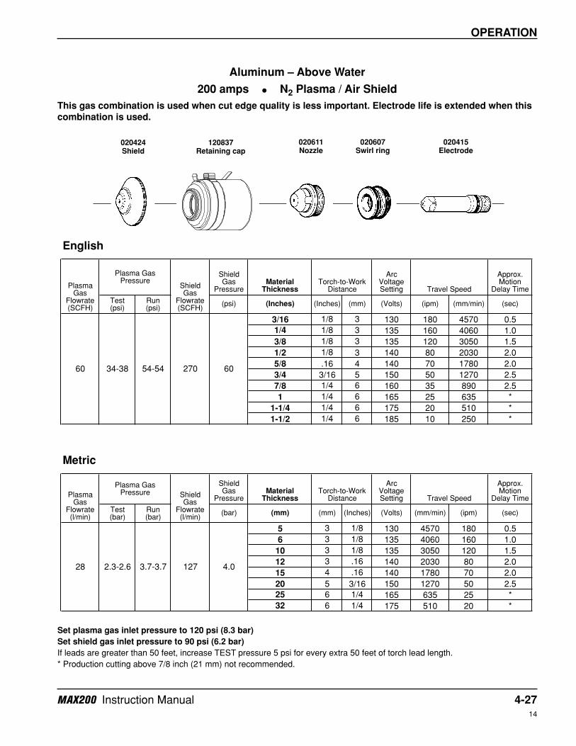
Aluminum – Above Water
200 amps • N2 Plasma / Air Shield
This gas combination is used when cut edge quality is less important. Electrode life is extended when this
combination is used.
Set plasma gas inlet pressure to 120 psi (8.3 bar)
Set shield gas inlet pressure to 90 psi (6.2 bar)
If leads are greater than 50 feet, increase TEST pressure 5 psi for every extra 50 feet of torch lead length.
* Production cutting above 7/8 inch (21 mm) not recommended.
020424Shield
020611Nozzle
120837Retaining cap
020415Electrode
020607Swirl ring
4-28 MAX200 Instruction Manual14
OPERATION
Shield Gas
PressureMaterial
Thickness
Arc Voltage Setting
Approx. Motion
Delay Time
Test (psi)
Run (psi)
(psi) (Inches) (Inches) (mm) (Volts) (ipm) (mm/min) (sec)
3/16 1/8 3 130 185 4700 0.5
1/4 1/8 3 135 160 4050 1.0
3/8 1/8 3 135 120 3050 2.0
1/2 1/8 3 140 95 2400 2.5
5/8 .16 4 140 70 1800 2.5
3/4 3/16 5 150 55 1400 3.0
7/8 1/4 6 160 42 10580 3.0
1 1/4 6 165 33 840 *
1-1/4 1/4 6 175 20 510 *
1-1/2 5/16 8 185 11 280 *
Shield Gas
PressureMaterial
Thickness
Arc Voltage Setting
Approx. Motion
Delay Time
Test (bar)
Run (bar)
(bar) (mm) (mm) (Inches) (Volts) (mm/min) (ipm) (sec)
5 3 1/8 130 4700 185 0.5
6 3 1/8 135 4050 160 1.0
10 3 1/8 135 3050 120 2.0
12 3 .16 140 2400 95 2.5
15 4 .16 140 1800 70 2.5
20 5 3/16 150 1400 55 3.0
25 6 1/4 165 840 33 *
32 6 1/4 175 510 20 *
English
Plasma Gas
Flowrate (SCFH)
Plasma Gas Pressure
Shield Gas
Flowrate (SCFH)
Torch-to-Work Distance Travel Speed
60 36-40 52-56 210 60
Metric
Plasma Gas
Flowrate (l/min)
Plasma Gas Pressure Shield
Gas Flowrate (l/min)
Torch-to-Work Distance Travel Speed
28 2.5-2.8 3.6-3.9 99 4.0
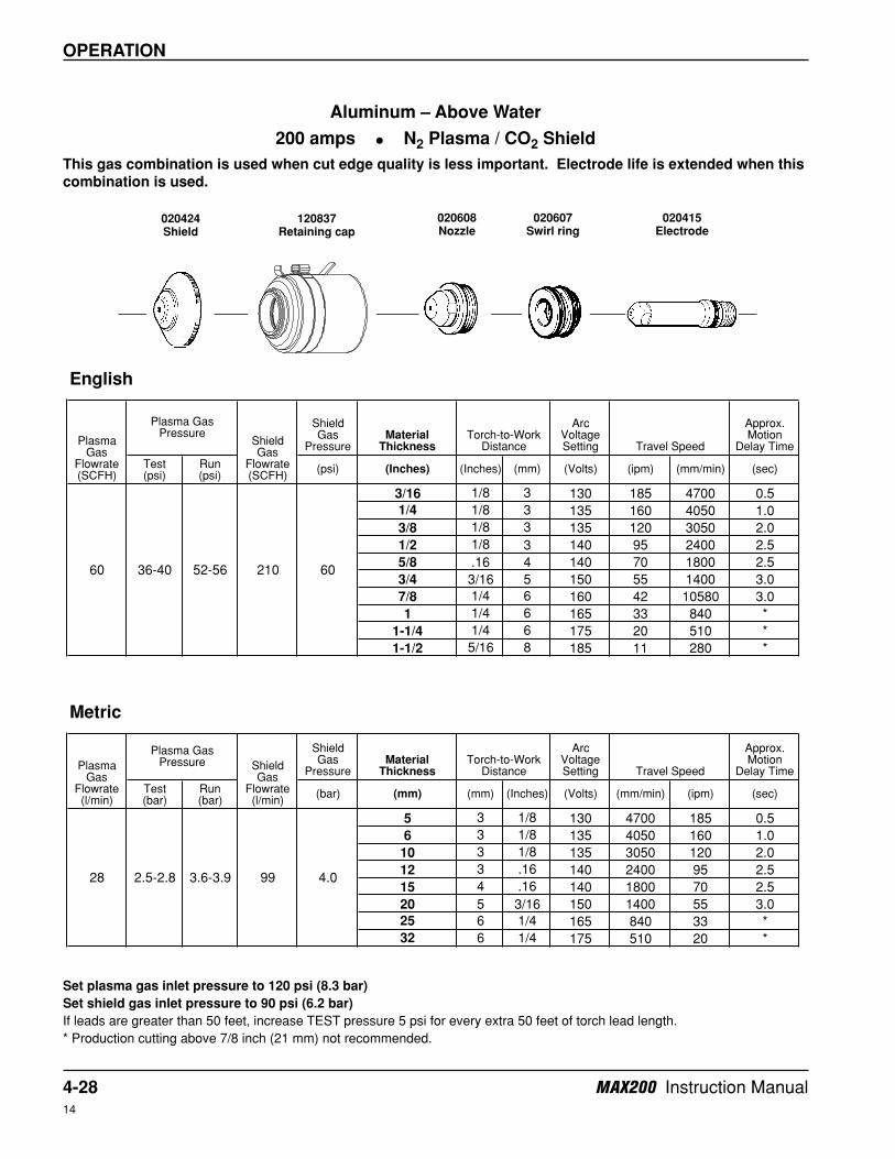
Aluminum – Above Water
200 amps • N2 Plasma / CO2 Shield
This gas combination is used when cut edge quality is less important. Electrode life is extended when this
combination is used.
Set plasma gas inlet pressure to 120 psi (8.3 bar)
Set shield gas inlet pressure to 90 psi (6.2 bar)
If leads are greater than 50 feet, increase TEST pressure 5 psi for every extra 50 feet of torch lead length.
* Production cutting above 7/8 inch (21 mm) not recommended.
020424Shield
020608Nozzle
120837Retaining cap
020415Electrode
020607Swirl ring
MAX200 Instruction Manual 4-2914
OPERATION
Shield Gas
PressureMaterial
Thickness
Arc Voltage Setting
Approx. Motion
Delay Time
Test (psi)
Run (psi)
(psi) (Inches) (Inches) (mm) (Volts) (ipm) (mm/min) (sec)
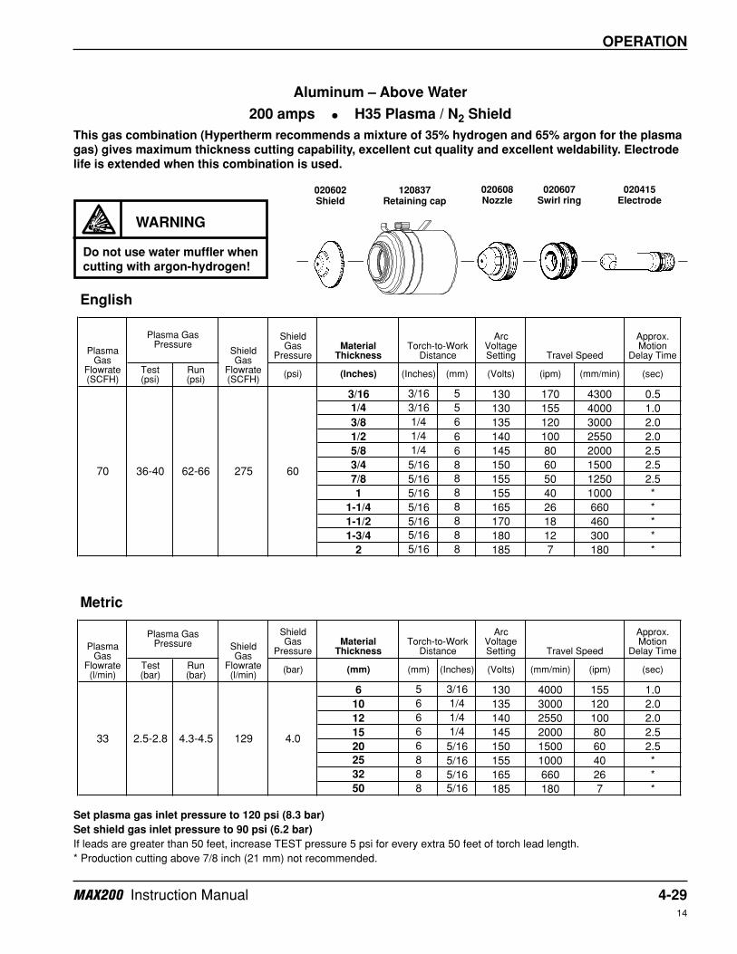
3/16 3/16 5 130 170 4300 0.5
1/4 3/16 5 130 155 4000 1.0
3/8 1/4 6 135 120 3000 2.0
1/2 1/4 6 140 100 2550 2.0
5/8 1/4 6 145 80 2000 2.5
3/4 5/16 8 150 60 1500 2.5
7/8 5/16 8 155 50 1250 2.5
1 5/16 8 155 40 1000 *
1-1/4 5/16 8 165 26 660 *
1-1/2 5/16 8 170 18 460 *
1-3/4 5/16 8 180 12 300 *
2 5/16 8 185 7 180 *
Shield Gas
PressureMaterial
Thickness
Arc Voltage Setting
Approx. Motion
Delay Time
Test (bar)
Run (bar)
(bar) (mm) (mm) (Inches) (Volts) (mm/min) (ipm) (sec)
6 5 3/16 130 4000 155 1.0
10 6 1/4 135 3000 120 2.0
12 6 1/4 140 2550 100 2.0
15 6 1/4 145 2000 80 2.5
20 6 5/16 150 1500 60 2.5
25 8 5/16 155 1000 40 *
32 8 5/16 165 660 26 *
50 8 5/16 185 180 7 *
4.033 2.5-2.8 4.3-4.5 129
Torch-to-Work Distance Travel Speed
Metric
Plasma Gas
Flowrate (l/min)
Plasma Gas Pressure Shield
Gas Flowrate (l/min)
Torch-to-Work Distance Travel Speed
70 36-40 62-66 275 60
English
Plasma Gas
Flowrate (SCFH)
Plasma Gas Pressure
Shield Gas
Flowrate (SCFH)
Set plasma gas inlet pressure to 120 psi (8.3 bar)
Set shield gas inlet pressure to 90 psi (6.2 bar)
If leads are greater than 50 feet, increase TEST pressure 5 psi for every extra 50 feet of torch lead length.
* Production cutting above 7/8 inch (21 mm) not recommended.
Aluminum – Above Water
200 amps • H35 Plasma / N2 Shield
This gas combination (Hypertherm recommends a mixture of 35% hydrogen and 65% argon for the plasma
gas) gives maximum thickness cutting capability, excellent cut quality and excellent weldability. Electrode
life is extended when this combination is used.
WARNING
Do not use water muffler when
cutting with argon-hydrogen!
020602Shield
020608Nozzle
120837Retaining cap
020415Electrode
020607Swirl ring
4-30 MAX200 Instruction Manual14
OPERATION
Shield Gas
PressureMaterial
Thickness
Arc Voltage Setting
Approx. Motion
Delay Time
Test (psi)
Run (psi)
(psi) (Inches) (Inches) (mm) (Volts) (ipm) (mm/min) (sec)
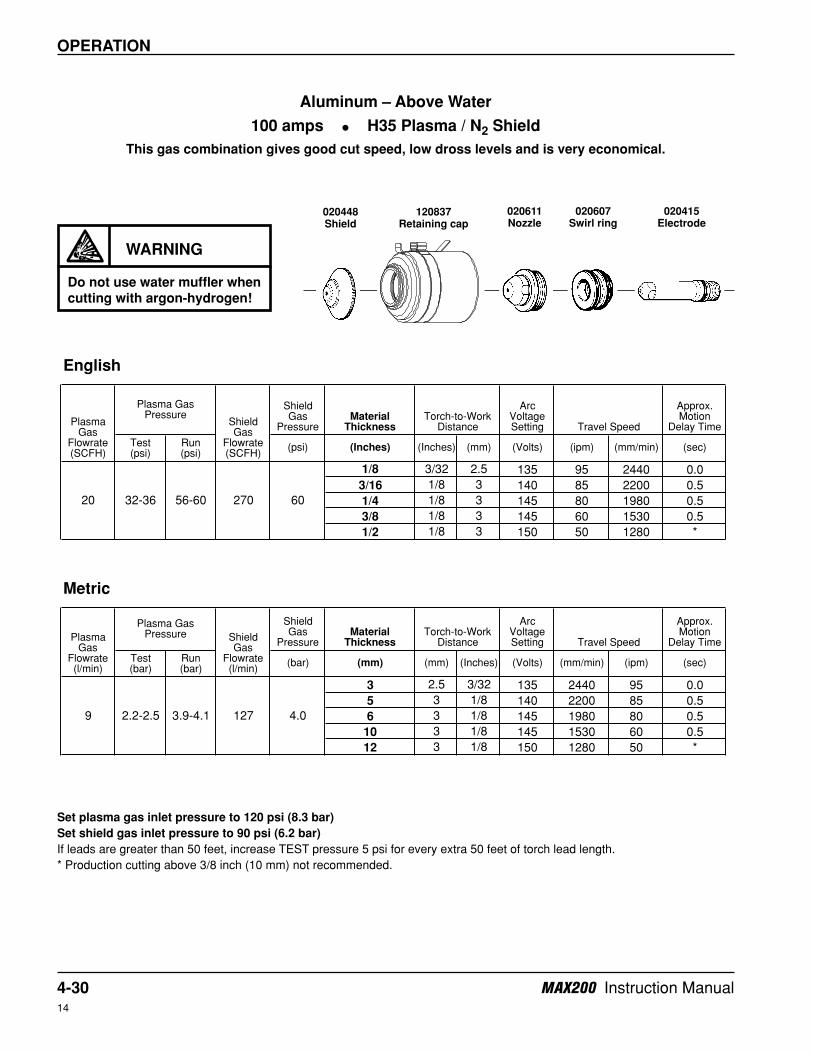
1/8 3/32 2.5 135 95 2440 0.0
3/16 1/8 3 140 85 2200 0.5
1/4 1/8 3 145 80 1980 0.5
3/8 1/8 3 145 60 1530 0.5
1/2 1/8 3 150 50 1280 *
Shield Gas
PressureMaterial
Thickness
Arc Voltage Setting
Approx. Motion
Delay Time
Test (bar)
Run (bar)
(bar) (mm) (mm) (Inches) (Volts) (mm/min) (ipm) (sec)
3 2.5 3/32 135 2440 95 0.0
5 3 1/8 140 2200 85 0.5
6 3 1/8 145 1980 80 0.5
10 3 1/8 145 1530 60 0.5
12 3 1/8 150 1280 50 *
Torch-to-Work Distance Travel Speed
9 2.2-2.5 3.9-4.1 127 4.0
Metric
Plasma Gas
Flowrate (l/min)
Plasma Gas Pressure Shield
Gas Flowrate (l/min)
Torch-to-Work Distance Travel Speed
20 32-36 56-60 270 60
English
Plasma Gas
Flowrate (SCFH)
Plasma Gas Pressure
Shield Gas
Flowrate (SCFH)
Set plasma gas inlet pressure to 120 psi (8.3 bar)
Set shield gas inlet pressure to 90 psi (6.2 bar)
If leads are greater than 50 feet, increase TEST pressure 5 psi for every extra 50 feet of torch lead length.
* Production cutting above 3/8 inch (10 mm) not recommended.
Aluminum – Above Water
100 amps • H35 Plasma / N2 Shield
This gas combination gives good cut speed, low dross levels and is very economical.
WARNING
Do not use water muffler when
cutting with argon-hydrogen!
020448Shield
020611Nozzle
120837Retaining cap
020415Electrode
020607Swirl ring
MAX200 Instruction Manual 4-3115
OPERATION
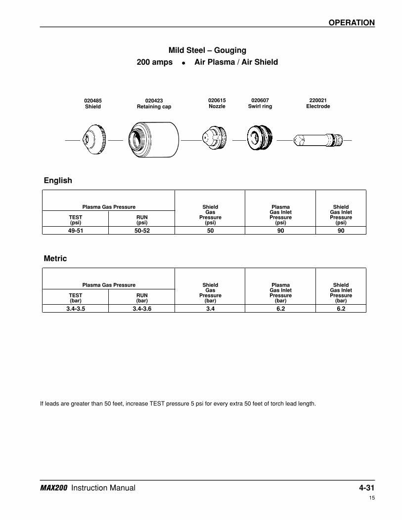
49-51 50-52 50 90 90
3.4-3.5 3.4-3.6 3.4 6.2 6.2
Shield Gas
Pressure (psi)
Plasma Gas Inlet Pressure
(psi)TEST (psi)
RUN (psi)
English
Shield Gas Inlet Pressure
(psi)
Shield Gas Inlet Pressure
(bar)RUN (bar)
Metric
Plasma Gas Pressure Shield Gas
Pressure (bar)
Plasma Gas Inlet Pressure
(bar)TEST (bar)
Plasma Gas Pressure
Mild Steel – Gouging
200 amps • Air Plasma / Air Shield
If leads are greater than 50 feet, increase TEST pressure 5 psi for every extra 50 feet of torch lead length.
020485Shield
020615Nozzle
020423Retaining cap
220021Electrode
020607Swirl ring
4-32 MAX200 Instruction Manual15
OPERATION
49-51 50-52 50 120 120
3.4-3.5 3.4-3.6 3.4 8.3 8.3
Shield Gas Inlet Pressure
(psi)TEST (psi)
RUN (psi)
Shield Gas Inlet Pressure
(bar)TEST (bar)
RUN (bar)
Metric
Plasma Gas Pressure Shield Gas
Pressure (bar)
Plasma Gas Inlet Pressure
(bar)
English
Plasma Gas Pressure Shield Gas
Pressure (psi)
Plasma Gas Inlet Pressure
(psi)
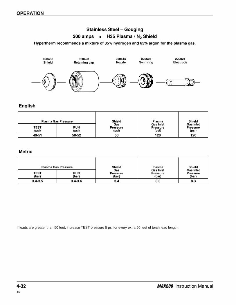
Stainless Steel – Gouging
200 amps • H35 Plasma / N2 Shield
Hypertherm recommends a mixture of 35% hydrogen and 65% argon for the plasma gas.
020485Shield
020615Nozzle
020423Retaining cap
220021Electrode
020607Swirl ring
If leads are greater than 50 feet, increase TEST pressure 5 psi for every extra 50 feet of torch lead length.
MAX200 Instruction Manual 4-3315
OPERATION
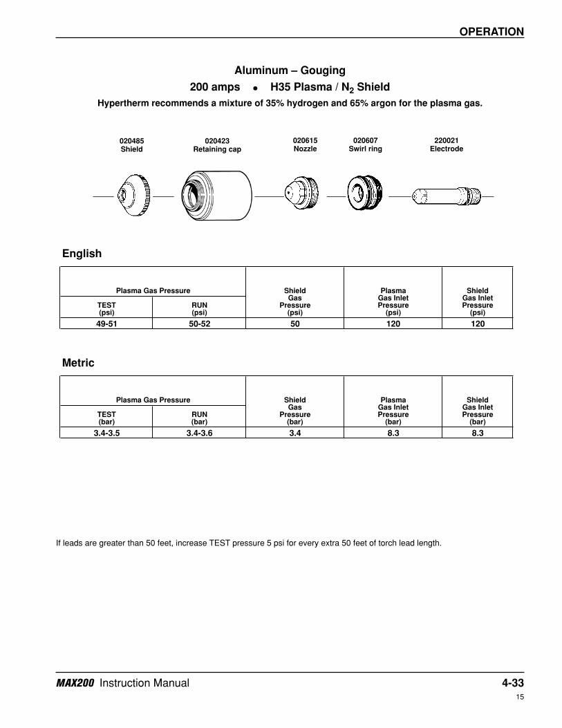
49-51 50-52 50 120 120
3.4-3.5 3.4-3.6 3.4 8.3 8.3
Shield Gas Inlet Pressure
(psi)TEST (psi)
RUN (psi)
Shield Gas Inlet Pressure
(bar)TEST (bar)
RUN (bar)
Metric
Plasma Gas Pressure Shield Gas
Pressure (bar)
Plasma Gas Inlet Pressure
(bar)
English
Plasma Gas Pressure Shield Gas
Pressure (psi)
Plasma Gas Inlet Pressure
(psi)
Aluminum – Gouging
200 amps • H35 Plasma / N2 Shield
Hypertherm recommends a mixture of 35% hydrogen and 65% argon for the plasma gas.
020485Shield
020615Nozzle
020423Retaining cap
220021Electrode
020607Swirl ring
If leads are greater than 50 feet, increase TEST pressure 5 psi for every extra 50 feet of torch lead length.
4-34 MAX200 Instruction Manual15
OPERATION
Shield Gas
PressureMaterial
Thickness
Arc Voltage Setting
Approx. Motion
Delay Time
Test (psi)
Run (psi)
(psi) (Inches) (Inches) (mm) (Volts) (ipm) (mm/min) (sec)
1/4 1/8 3 130 130 3300 0.5
3/8 1/8 3 135 95 2400 1.0
1/2 1/8 3 140 75 1900 2.0
5/8 .16 4 145 50 1200 2.0
3/4 3/16 5 150 35 850 2.5
7/8 1/4 6 155 20 530 3.0
1 1/4 6 165 15 400 3.0
Shield Gas
PressureMaterial
Thickness
Arc Voltage Setting
Approx. Motion
Delay Time
Test (bar)
Run (bar)
(bar) (mm) (mm) (Inches) (Volts) (mm/min) (ipm) (sec)
6 3 1/8 130 3300 130 0.5
8 3 1/8 135 2700 110 0.5
10 3 1/8 135 2400 95 1.0
12 3 1/8 140 1900 75 2.0
15 4 .16 145 1200 50 2.0
20 5 3/16 150 850 35 2.5
25 6 1/4 165 400 15 3.0
English
Plasma Gas
Flowrate (SCFH)
Plasma Gas Pressure
Shield Gas
Flowrate (SCFH)
Torch-to-Work Distance Travel Speed
66 44-48 58-62 280 70
Metric
Plasma Gas
Flowrate (l/min)
Plasma Gas Pressure Shield
Gas Flowrate (l/min)
Torch-to-Work Distance Travel Speed
31 3.0-3.3 4.0-4.3 132 4.8
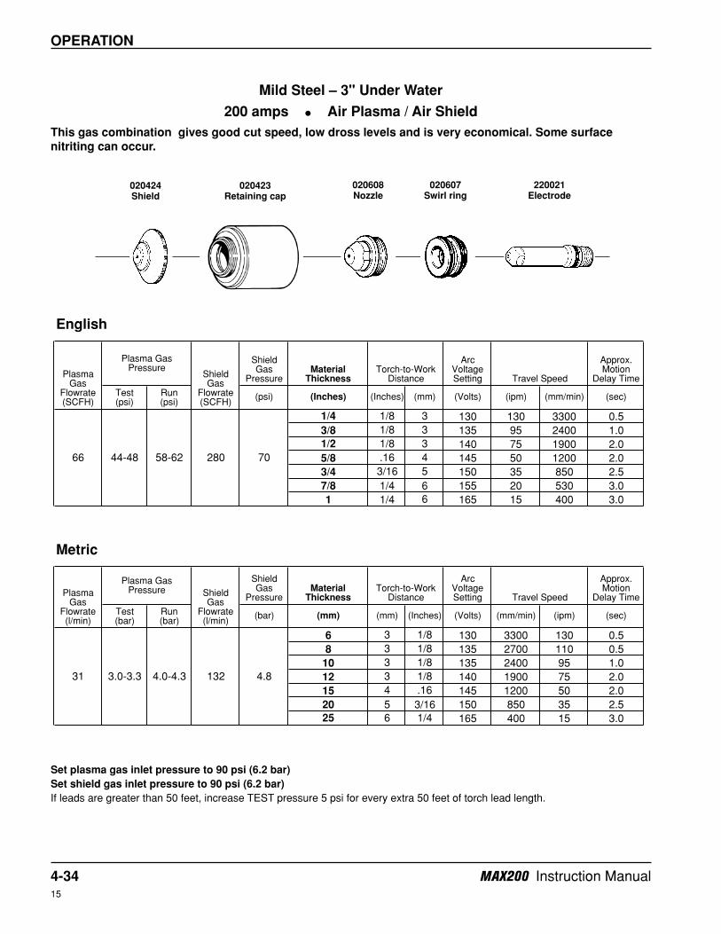
Mild Steel – 3" Under Water
200 amps • Air Plasma / Air Shield
This gas combination gives good cut speed, low dross levels and is very economical. Some surface
nitriting can occur.
Set plasma gas inlet pressure to 90 psi (6.2 bar)
Set shield gas inlet pressure to 90 psi (6.2 bar)
If leads are greater than 50 feet, increase TEST pressure 5 psi for every extra 50 feet of torch lead length.
020424Shield
020608Nozzle
020423Retaining cap
220021Electrode
020607Swirl ring
MAX200 Instruction Manual 4-3515
OPERATION
Shield Gas
PressureMaterial
Thickness
Arc Voltage Setting
Approx. Motion
Delay Time
Test (psi)
Run (psi)
(psi) (Inches) (Inches) (mm) (Volts) (ipm) (mm/min) (sec)
1/8 5/64 2 130 120 3050 0.0
3/16 1/8 3 135 90 2300 0.5
1/4 1/8 3 140 70 1730 0.5
3/8 1/8 3 145 42 1050 0.5
1/2 1/8 3 145 28 700 *
Shield Gas
PressureMaterial
Thickness
Arc Voltage Setting
Approx. Motion
Delay Time
Test (bar)
Run (bar)
(bar) (mm) (mm) (Inches) (Volts) (mm/min) (ipm) (sec)
3 2 5/64 130 3050 120 0.0
5 3 1/8 135 2300 90 0.5
6 3 1/8 140 1730 70 0.5
10 3 1/8 145 1050 42 0.5
12 3 1/8 145 700 28 *
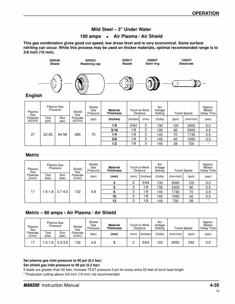
Metric – 80 amps • Air Plasma / Air Shield
Shield Gas
PressureMaterial
Thickness
Arc Voltage Setting
Approx. Motion
Delay Time
Test (bar)
Run (bar)
(bar) (mm) (mm) (Inches) (Volts) (mm/min) (ipm) (sec)
17 1.5-1.8 3.3-3.6 132 4.8 2 2 5/64 120 6050 240 0.0
Travel Speed
37 22-26 54-58 280 70
17 1.5-1.8 3.7-4.0 132
Plasma Gas
Flowrate (l/min)
Plasma Gas Pressure Shield
Gas Flowrate (l/min)
Torch-to-Work Distance
Torch-to-Work Distance Travel Speed
4.8
Metric
Plasma Gas
Flowrate (l/min)
Plasma Gas Pressure Shield
Gas Flowrate (l/min)
Torch-to-Work Distance Travel Speed
English
Plasma Gas
Flowrate (SCFH)
Plasma Gas Pressure
Shield Gas
Flowrate (SCFH)
Mild Steel – 3" Under Water
100 amps • Air Plasma / Air Shield
This gas combination gives good cut speed, low dross level and is very economical. Some surface
nitriting can occur. While this process may be used on thicker materials, optimal recommended range is to
3/8 inch (10 mm).
Set plasma gas inlet pressure to 90 psi (6.2 bar)
Set shield gas inlet pressure to 90 psi (6.2 bar)
If leads are greater than 50 feet, increase TEST pressure 5 psi for every extra 50 feet of torch lead length.
* Production cutting above 3/8 inch (10 mm) not recommended.
020448Shield
020611Nozzle
020423Retaining cap
120547Electrode
020607Swirl ring

4-36 MAX200 Instruction Manual15
OPERATION
Shield Gas
PressureMaterial
Thickness
Arc Voltage Setting
Approx. Motion
Delay Time
Test (psi)
Run (psi)
(psi) (Inches) (Inches) (mm) (Volts) (ipm) (mm/min) (sec)
1/4 1/8 3 125 145 3700 0.5
3/8 1/8 3 130 80 2000 1.0
1/2 1/8 3 130 70 1800 2.0
5/8 .16 4 135 60 1500 2.0
3/4 3/16 5 140 48 1200 2.5
7/8 1/4 6 140 38 950 3.0
1 1/4 6 145 25 680 3.0
Shield Gas
PressureMaterial
Thickness
Arc Voltage Setting
Approx. Motion
Delay Time
Test (bar)
Run (bar)
(bar) (mm) (mm) (Inches) (Volts) (mm/min) (ipm) (sec)
6 3 1/8 125 3700 145 0.5
8 3 1/8 125 2800 110 0.5
10 3 1/8 130 2000 80 1.0
12 3 1/8 130 1800 70 2.0
15 4 .16 135 1500 60 2.0
20 5 3/16 140 1200 48 2.5
25 6 1/4 145 680 25 3.0
English
Plasma Gas
Flowrate (SCFH)
Plasma Gas Pressure
Shield Gas
Flowrate (SCFH)
Torch-to-Work Distance Travel Speed
72 48-52 64-68 280 70
Metric
Plasma Gas
Flowrate (l/min)
Plasma Gas Pressure Shield
Gas Flowrate (l/min)
Torch-to-Work Distance Travel Speed
34 3.33-3.6 4.4-4.7 132 4.8
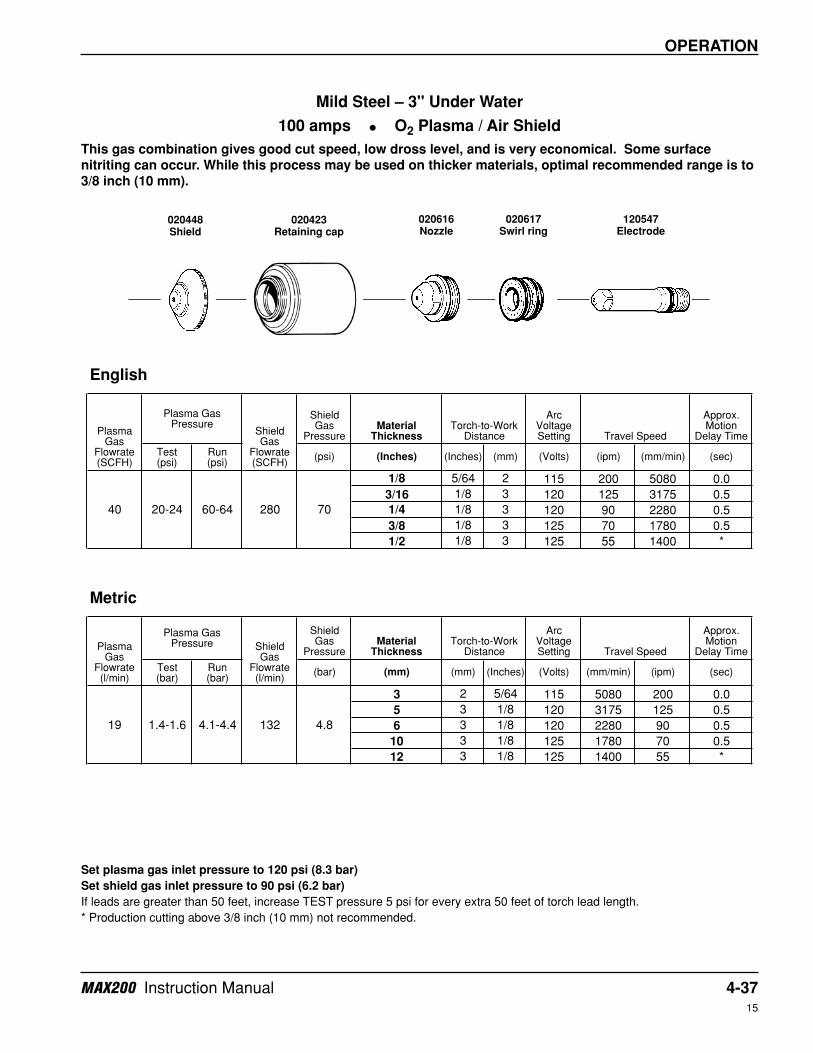
Mild Steel – 3" Under Water
200 amps • O2 Plasma / Air Shield
This gas combination gives superior cut speed, minimum dross, minimum amount of surface nitriting and
excellent weldability.
Set plasma gas inlet pressure to 120 psi (8.3 bar)
Set shield gas inlet pressure to 90 psi (6.2 bar)
If leads are greater than 50 feet, increase TEST pressure 5 psi for every extra 50 feet of torch lead length.
020424Shield
020605Nozzle
020423Retaining cap
220021Electrode
020604Swirl ring
MAX200 Instruction Manual 4-3715
OPERATION
Shield Gas
PressureMaterial
Thickness
Arc Voltage Setting
Approx. Motion
Delay Time
Test (psi)
Run (psi)
(psi) (Inches) (Inches) (mm) (Volts) (ipm) (mm/min) (sec)
1/8 5/64 2 115 200 5080 0.0
3/16 1/8 3 120 125 3175 0.5
1/4 1/8 3 120 90 2280 0.5
3/8 1/8 3 125 70 1780 0.5
1/2 1/8 3 125 55 1400 *
Shield Gas
PressureMaterial
Thickness
Arc Voltage Setting
Approx. Motion
Delay Time
Test (bar)
Run (bar)
(bar) (mm) (mm) (Inches) (Volts) (mm/min) (ipm) (sec)
3 2 5/64 115 5080 200 0.0
5 3 1/8 120 3175 125 0.5
6 3 1/8 120 2280 90 0.5
10 3 1/8 125 1780 70 0.5
12 3 1/8 125 1400 55 *
English
Plasma Gas
Flowrate (SCFH)
Plasma Gas Pressure
Shield Gas
Flowrate (SCFH)
Torch-to-Work Distance Travel Speed
40 20-24 60-64 280 70
Metric
Plasma Gas
Flowrate (l/min)
Plasma Gas Pressure Shield
Gas Flowrate (l/min)
Torch-to-Work Distance Travel Speed
19 1.4-1.6 4.1-4.4 132 4.8
Mild Steel – 3" Under Water
100 amps • O2 Plasma / Air Shield
This gas combination gives good cut speed, low dross level, and is very economical. Some surface
nitriting can occur. While this process may be used on thicker materials, optimal recommended range is to
3/8 inch (10 mm).
Set plasma gas inlet pressure to 120 psi (8.3 bar)
Set shield gas inlet pressure to 90 psi (6.2 bar)
If leads are greater than 50 feet, increase TEST pressure 5 psi for every extra 50 feet of torch lead length.
* Production cutting above 3/8 inch (10 mm) not recommended.
020448Shield
020616Nozzle
020423Retaining cap
120547Electrode
020617Swirl ring
4-38 MAX200 Instruction Manual15
OPERATION
Shield Gas
PressureMaterial
Thickness
Arc Voltage Setting
Approx. Motion
Delay Time
Test (psi)
Run (psi)
(psi) (Inches) (Inches) (mm) (Volts) (ipm) (mm/min) (sec)
3/16 1/8 3 125 210 5320 0.0
1/4 1/8 3 130 180 4500 0.5
3/8 1/8 3 135 125 3150 1.0
1/2 1/8 3 140 90 2300 2.0
5/8 .16 4 145 60 1520 2.0
3/4 3/16 5 145 45 1150 2.5
7/8 1/4 6 150 30 750 3.0
1 1/4 6 155 22 570 *
Shield Gas
PressureMaterial
Thickness
Arc Voltage Setting
Approx. Motion
Delay Time
Test (bar)
Run (bar)
(bar) (mm) (mm) (Inches) (Volts) (mm/min) (ipm) (sec)
5 3 1/8 125 5320 210 0.0
6 3 1/8 130 4500 180 0.5
10 3 1/8 135 3150 125 1.0
12 3 1/8 140 2300 90 2.0
15 4 .16 145 1520 60 2.0
20 5 3/16 145 1150 45 2.5
25 6 1/4 155 570 22 *
English
Metric
Torch-to-Work Distance Travel Speed
Plasma Gas
Flowrate (SCFH)
Plasma Gas Pressure
Shield Gas
Flowrate (SCFH)
Torch-to-Work Distance Travel Speed
31 3.0-3.3 4.0-4.3 132 4.8
Plasma Gas
Flowrate (l/min)
Plasma Gas Pressure Shield
Gas Flowrate (l/min)
7066 44-48 58-62 280
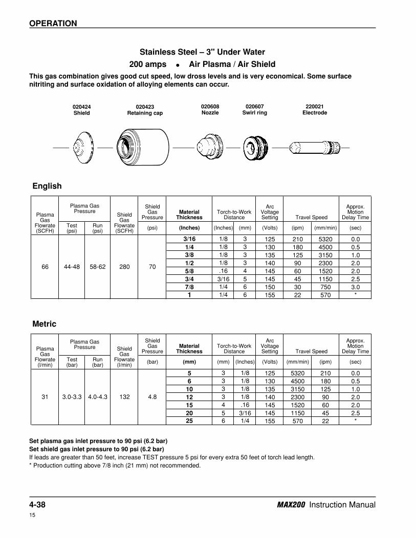
Stainless Steel – 3" Under Water
200 amps • Air Plasma / Air Shield
This gas combination gives good cut speed, low dross levels and is very economical. Some surface
nitriting and surface oxidation of alloying elements can occur.
Set plasma gas inlet pressure to 90 psi (6.2 bar)
Set shield gas inlet pressure to 90 psi (6.2 bar)
If leads are greater than 50 feet, increase TEST pressure 5 psi for every extra 50 feet of torch lead length.
* Production cutting above 7/8 inch (21 mm) not recommended.
020424Shield
020608Nozzle
020423Retaining cap
220021Electrode
020607Swirl ring
MAX200 Instruction Manual 4-3915
OPERATION
Shield Gas
PressureMaterial
Thickness
Arc Voltage Setting
Approx. Motion
Delay Time
Test (psi)
Run (psi)
(psi) (Inches) (Inches) (mm) (Volts) (ipm) (mm/min) (sec)
1/8 5/64 2 125 135 3400 0.0
3/16 1/8 3 130 100 2520 0.5
1/4 1/8 3 135 65 1720 0.5
3/8 1/8 3 140 45 1120 0.5
1/2 1/8 3 145 25 670 *
Shield Gas
PressureMaterial
Thickness
Arc Voltage Setting
Approx. Motion
Delay Time
Test (bar)
Run (bar)
(bar) (mm) (mm) (Inches) (Volts) (mm/min) (ipm) (sec)
3 2 5/64 125 3400 135 0.0
5 3 1/8 130 2520 100 0.5
6 3 1/8 135 1720 65 0.5
10 3 1/8 140 1120 45 0.5
12 3 1/8 145 670 25 *
English
Plasma Gas
Flowrate (SCFH)
Plasma Gas Pressure
Shield Gas
Flowrate (SCFH)
Torch-to-Work Distance Travel Speed
37 22-26 54-58 280 70
Metric
Plasma Gas
Flowrate (l/min)
Plasma Gas Pressure Shield
Gas Flowrate (l/min)
Torch-to-Work Distance Travel Speed
17 1.5-1.8 3.7-4.0 132 4.8
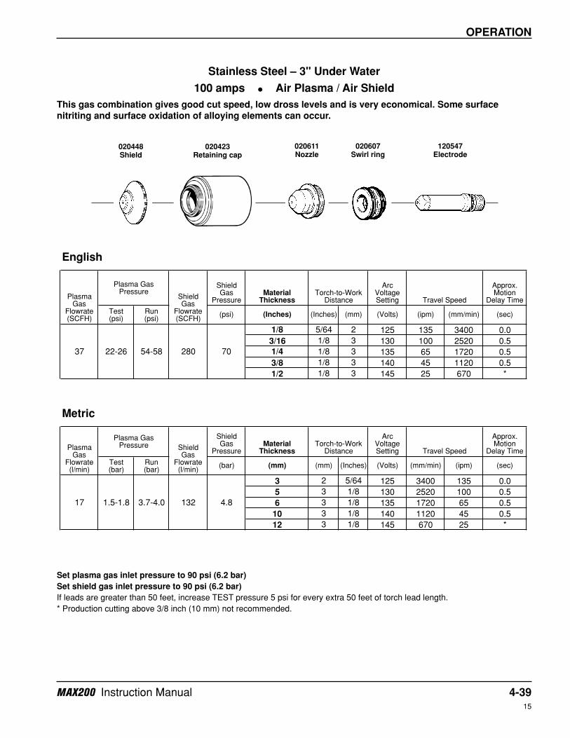
Stainless Steel – 3" Under Water
100 amps • Air Plasma / Air Shield
This gas combination gives good cut speed, low dross levels and is very economical. Some surface
nitriting and surface oxidation of alloying elements can occur.
Set plasma gas inlet pressure to 90 psi (6.2 bar)
Set shield gas inlet pressure to 90 psi (6.2 bar)
If leads are greater than 50 feet, increase TEST pressure 5 psi for every extra 50 feet of torch lead length.
* Production cutting above 3/8 inch (10 mm) not recommended.
020448Shield
020611Nozzle
020423Retaining cap
120547Electrode
020607Swirl ring
4-40 MAX200 Instruction Manual15
OPERATION
Shield Gas
PressureMaterial
Thickness
Arc Voltage Setting
Approx. Motion
Delay Time
Test (psi)
Run (psi)
(psi) (Inches) (Inches) (mm) (Volts) (ipm) (mm/min) (sec)
3/16 1/8 3 125 130 3250 0.0
1/4 1/8 3 130 110 2750 0.5
3/8 1/8 3 135 85 2160 1.0
1/2 1/8 3 140 60 1520 2.0
5/8 .16 4 145 45 1140 2.0
3/4 3/16 5 145 30 800 2.5
Shield Gas
PressureMaterial
Thickness
Arc Voltage Setting
Approx. Motion
Delay Time
Test (bar)
Run (bar)
(bar) (mm) (mm) (Inches) (Volts) (mm/min) (ipm) (sec)
5 3 1/8 125 3250 130 0.0
6 3 1/8 130 2750 110 0.5
10 3 1/8 135 2160 85 1.0
12 3 1/8 140 1520 60 2.0
15 4 .16 145 1140 45 2.0
20 5 3/16 145 800 30 2.5
Torch-to-Work Distance Travel Speed
English
Plasma Gas
Flowrate (SCFH)
Plasma Gas Pressure
Shield Gas
Flowrate (SCFH)
Torch-to-Work Distance Travel Speed
Metric
Plasma Gas
Flowrate (l/min)
Plasma Gas Pressure Shield
Gas Flowrate (l/min)
70
28 2.3-2.6 3.5-3.7 132 4.8
60 34-38 50-54 280
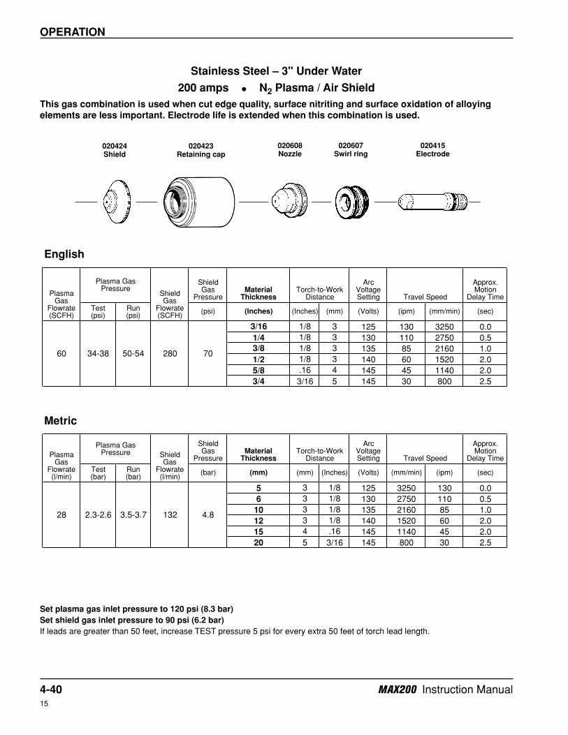
Stainless Steel – 3" Under Water
200 amps • N2 Plasma / Air Shield
This gas combination is used when cut edge quality, surface nitriting and surface oxidation of alloying
elements are less important. Electrode life is extended when this combination is used.
Set plasma gas inlet pressure to 120 psi (8.3 bar)
Set shield gas inlet pressure to 90 psi (6.2 bar)
If leads are greater than 50 feet, increase TEST pressure 5 psi for every extra 50 feet of torch lead length.
020424Shield
020608Nozzle
020423Retaining cap
020415Electrode
020607Swirl ring
MAX200 Instruction Manual 4-4115
OPERATION
Shield Gas
PressureMaterial
Thickness
Arc Voltage Setting
Approx. Motion
Delay Time
Test (psi)
Run (psi)
(psi) (Inches) (Inches) (mm) (Volts) (ipm) (mm/min) (sec)
3/16 1/8 3 125 180 4550 0.5
1/4 1/8 3 130 150 3850 1.0
3/8 1/8 3 135 110 2700 1.5
1/2 1/8 3 140 75 1920 2.0
5/8 .16 4 145 50 1350 2.0
3/4 3/16 5 145 38 950 2.5
7/8 1/4 5 150 28 700 3.0
Shield Gas
PressureMaterial
Thickness
Arc Voltage Setting
Approx. Motion
Delay Time
Test (bar)
Run (bar)
(bar) (mm) (mm) (Inches) (Volts) (mm/min) (ipm) (sec)
5 3 1/8 125 4550 180 0.5
6 3 1/8 130 3850 150 1.0
10 3 1/8 135 2700 110 1.5
12 3 1/8 140 1920 75 2.0
15 4 .16 145 1350 50 2.0
20 5 3/16 145 950 38 2.5
Torch-to-Work Distance Travel Speed
English
Plasma Gas
Flowrate (SCFH)
Plasma Gas Pressure
Shield Gas
Flowrate (SCFH)
Metric
Plasma Gas
Flowrate (l/min)
Plasma Gas Pressure Shield
Gas Flowrate (l/min)
Torch-to-Work Distance Travel Speed
28 2.5-2.8 3.6-3.9 99 4.8
7060 36-40 52-56 210
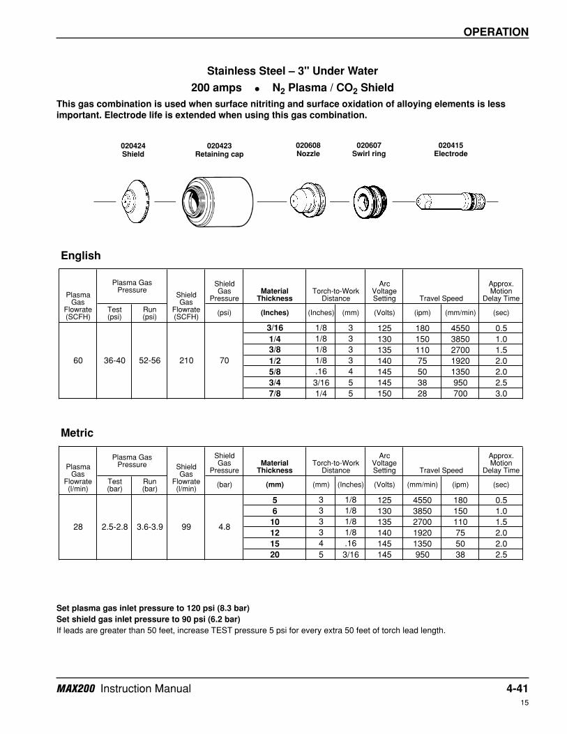
Stainless Steel – 3" Under Water
200 amps • N2 Plasma / CO2 Shield
This gas combination is used when surface nitriting and surface oxidation of alloying elements is less
important. Electrode life is extended when using this gas combination.
Set plasma gas inlet pressure to 120 psi (8.3 bar)
Set shield gas inlet pressure to 90 psi (6.2 bar)
If leads are greater than 50 feet, increase TEST pressure 5 psi for every extra 50 feet of torch lead length.
020424Shield
020608Nozzle
020423Retaining cap
020415Electrode
020607Swirl ring
4-42 MAX200 Instruction Manual15
OPERATION
Shield Gas
PressureMaterial
Thickness
Arc Voltage Setting
Approx. Motion
Delay Time
Test (psi)
Run (psi)
(psi) (Inches) (Inches) (mm) (Volts) (ipm) (mm/min) (sec)
3/16 1/8 3 135 210 5300 0.5
1/4 1/8 3 140 170 4300 1.0
3/8 1/8 3 145 125 3150 2.0
1/2 1/8 3 150 90 2240 2.5
5/8 .16 4 155 65 1650 3.0
3/4 3/16 5 160 45 1150 3.0
Shield Gas
PressureMaterial
Thickness
Arc Voltage Setting
Approx. Motion
Delay Time
Test (bar)
Run (bar)
(bar) (mm) (mm) (Inches) (Volts) (mm/min) (ipm) (sec)
5 3 1/8 135 5300 210 0.5
6 3 1/8 140 4300 170 1.0
10 3 1/8 145 3150 125 2.0
12 3 1/8 150 2240 90 2.5
15 4 .16 155 1650 65 3.0
20 5 3/16 160 1150 45 3.0
English
Plasma Gas
Flowrate (SCFH)
Plasma Gas Pressure
Shield Gas
Flowrate (SCFH)
Torch-to-Work Distance Travel Speed
66 44-48 58-62 280 70
Metric
Plasma Gas
Flowrate (l/min)
Plasma Gas Pressure Shield
Gas Flowrate (l/min)
Torch-to-Work Distance Travel Speed
31 3.0-3.3 4.0-4.3 132 4.8
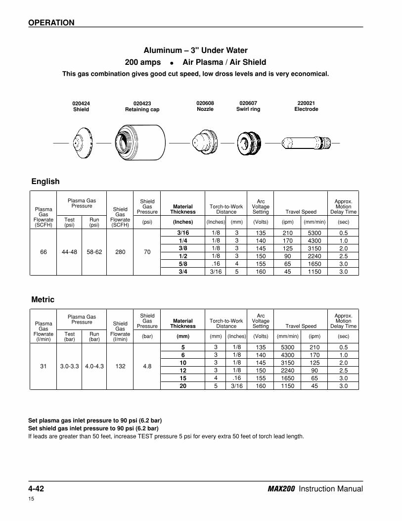
Aluminum – 3" Under Water
200 amps • Air Plasma / Air Shield
This gas combination gives good cut speed, low dross levels and is very economical.
Set plasma gas inlet pressure to 90 psi (6.2 bar)
Set shield gas inlet pressure to 90 psi (6.2 bar)
If leads are greater than 50 feet, increase TEST pressure 5 psi for every extra 50 feet of torch lead length.
020424Shield
020608Nozzle
020423Retaining cap
220021Electrode
020607Swirl ring
MAX200 Instruction Manual 4-4315
OPERATION
Shield Gas
PressureMaterial
Thickness
Arc Voltage Setting
Approx. Motion
Delay Time
Test (psi)
Run (psi)
(psi) (Inches) (Inches) (mm) (Volts) (ipm) (mm/min) (sec)
1/8 5/64 2 135 100 2650 0.0
3/16 1/8 3 140 80 2050 0.5
1/4 1/8 3 145 60 1510 0.5
3/8 1/8 3 150 40 1000 0.5
1/2 1/8 3 155 30 750 *
Shield Gas
PressureMaterial
Thickness
Arc Voltage Setting
Approx. Motion
Delay Time
Test (bar)
Run (bar)
(bar) (mm) (mm) (Inches) (Volts) (mm/min) (ipm) (sec)
3 2 5/64 135 2650 100 0.0
5 3 1/8 140 2050 80 0.5
6 3 1/8 145 1510 60 0.5
10 3 1/8 150 1000 40 0.5
12 3 1/8 155 750 30 *
English
Plasma Gas
Flowrate (SCFH)
Plasma Gas Pressure
Shield Gas
Flowrate (SCFH)
Torch-to-Work Distance Travel Speed
37 22-26 54-58 280 70
Metric
Plasma Gas
Flowrate (l/min)
Plasma Gas Pressure Shield
Gas Flowrate (l/min)
Torch-to-Work Distance Travel Speed
17 1.5-1.8 3.7-4.0 132 4.8
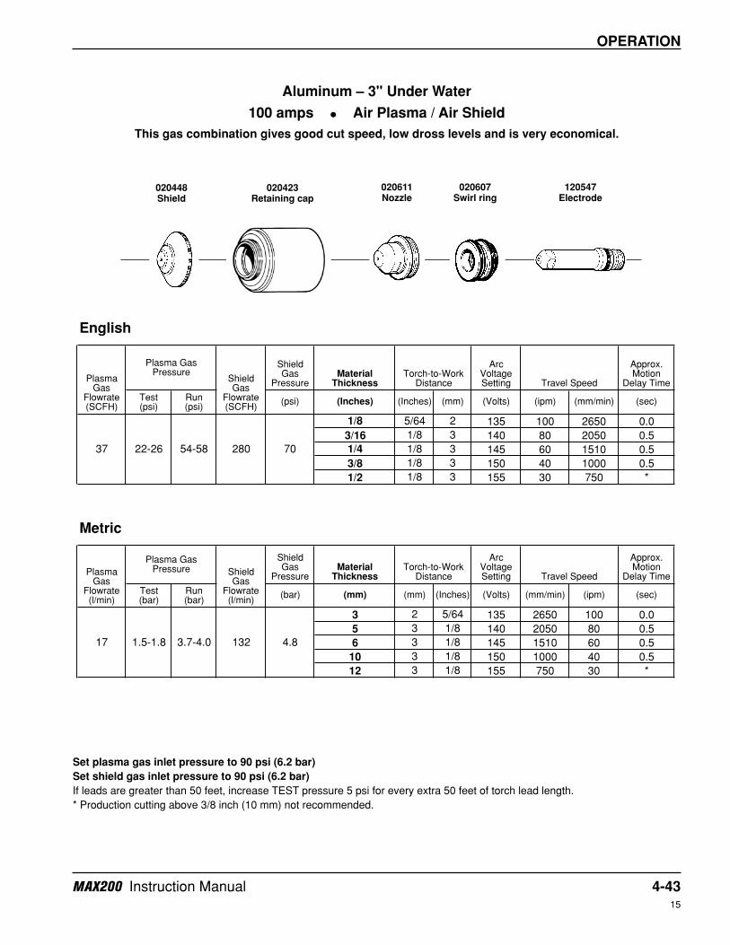
Aluminum – 3" Under Water
100 amps • Air Plasma / Air Shield
This gas combination gives good cut speed, low dross levels and is very economical.
Set plasma gas inlet pressure to 90 psi (6.2 bar)
Set shield gas inlet pressure to 90 psi (6.2 bar)
If leads are greater than 50 feet, increase TEST pressure 5 psi for every extra 50 feet of torch lead length.
* Production cutting above 3/8 inch (10 mm) not recommended.
020448Shield
020611Nozzle
020423Retaining cap
120547Electrode
020607Swirl ring
4-44 MAX200 Instruction Manual15
OPERATION
Shield Gas
PressureMaterial
Thickness
Arc Voltage Setting
Approx. Motion
Delay Time
Test (psi)
Run (psi)
(psi) (Inches) (Inches) (mm) (Volts) (ipm) (mm/min) (sec)
3/16 1/8 3 135 170 4350 0.5
1/4 1/8 3 140 140 3650 1.0
3/8 1/8 3 140 100 2600 1.5
1/2 1/8 3 145 65 1620 2.0
5/8 .16 4 145 55 1350 2.5
3/4 3/16 5 155 35 890 3.0
7/8 1/4 5 165 25 620 3.0
Shield Gas
PressureMaterial
Thickness
Arc Voltage Setting
Approx. Motion
Delay Time
Test (bar)
Run (bar)
(bar) (mm) (mm) (Inches) (Volts) (mm/min) (ipm) (sec)
5 3 1/8 135 4350 170 0.5
6 3 1/8 140 3650 140 1.0
10 3 1/8 140 2600 100 1.5
12 3 1/8 145 1620 65 2.0
15 4 .16 145 1350 55 2.5
20 5 3/16 155 890 35 3.0
English
Plasma Gas
Flowrate (SCFH)
Plasma Gas Pressure
Shield Gas
Flowrate (SCFH)
Torch-to-Work Distance Travel Speed
60 34-38 50-54 280 70
Metric
Plasma Gas
Flowrate (l/min)
Plasma Gas Pressure Shield
Gas Flowrate (l/min)
Torch-to-Work Distance Travel Speed
28 2.3-2.6 3.4-3.7 132 4.8
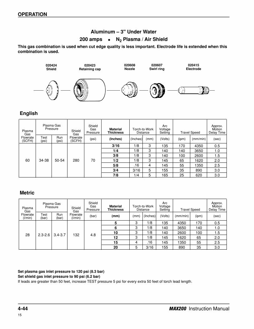
Aluminum – 3" Under Water
200 amps • N2 Plasma / Air Shield
This gas combination is used when cut edge quality is less important. Electrode life is extended when this
combination is used.
Set plasma gas inlet pressure to 120 psi (8.3 bar)
Set shield gas inlet pressure to 90 psi (6.2 bar)
If leads are greater than 50 feet, increase TEST pressure 5 psi for every extra 50 feet of torch lead length.
020424Shield
020608Nozzle
020423Retaining cap
020415Electrode
020607Swirl ring
MAX200 Instruction Manual 4-4515
OPERATION
Shield Gas
PressureMaterial
Thickness
Arc Voltage Setting
Approx. Motion
Delay Time
Test (psi)
Run (psi)
(psi) (Inches) (Inches) (mm) (Volts) (ipm) (mm/min) (sec)
3/16 1/8 3 130 175 4450 0.5
1/4 1/8 3 135 145 3650 1.0
3/8 1/8 3 140 100 2600 2.0
1/2 1/8 3 145 75 1820 2.5
5/8 .16 4 145 55 1350 2.5
3/4 3/16 5 155 40 980 3.0
7/8 1/4 5 165 30 750 3.0
Shield Gas
PressureMaterial
Thickness
Arc Voltage Setting
Approx. Motion
Delay Time
Test (bar)
Run (bar)
(bar) (mm) (mm) (Inches) (Volts) (mm/min) (ipm) (sec)
5 3 1/8 130 4450 175 0.5
6 3 1/8 135 3650 145 1.0
10 3 1/8 140 2600 100 2.0
12 3 1/8 145 1820 75 2.5
15 4 .16 145 1350 55 2.5
20 5 3/16 155 980 40 3.0
English
Plasma Gas
Flowrate (SCFH)
Plasma Gas Pressure
Shield Gas
Flowrate (SCFH)
Torch-to-Work Distance Travel Speed
60 36-40 52-56 220 70
Metric
Plasma Gas
Flowrate (l/min)
Plasma Gas Pressure Shield
Gas Flowrate (l/min)
Torch-to-Work Distance Travel Speed
28 2.5-2.8 3.6-3.9 103 4.8
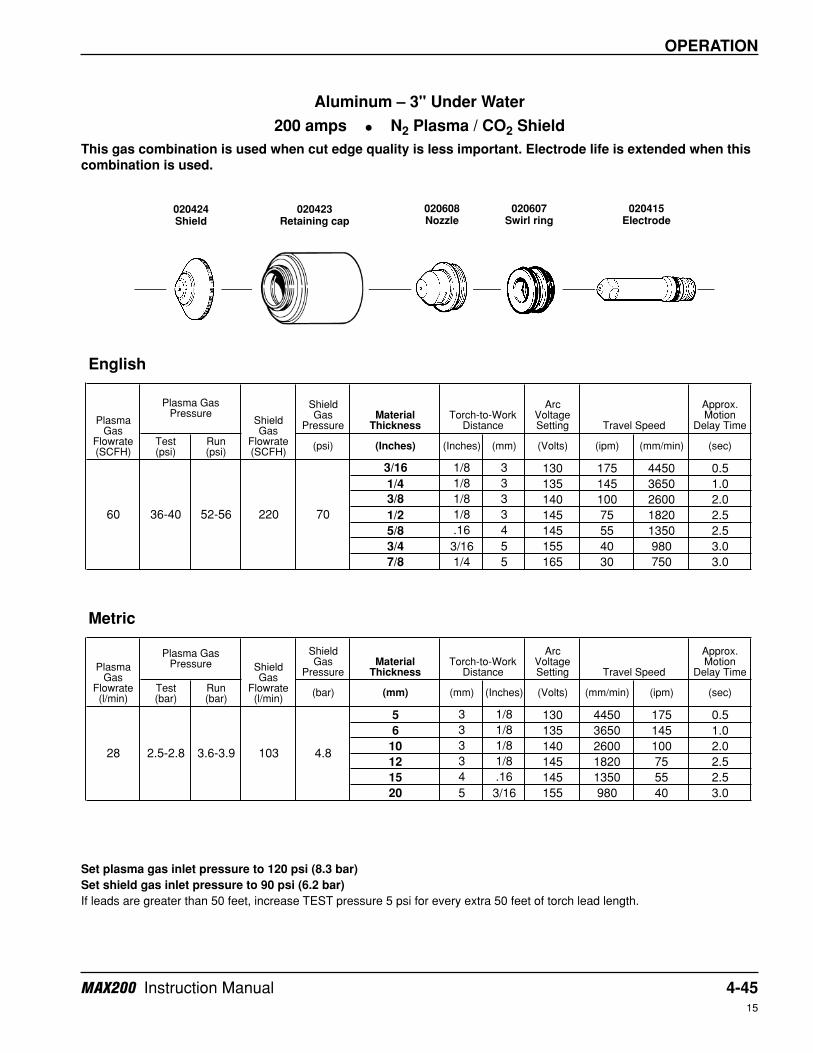
Aluminum – 3" Under Water
200 amps • N2 Plasma / CO2 Shield
This gas combination is used when cut edge quality is less important. Electrode life is extended when this
combination is used.
Set plasma gas inlet pressure to 120 psi (8.3 bar)
Set shield gas inlet pressure to 90 psi (6.2 bar)
If leads are greater than 50 feet, increase TEST pressure 5 psi for every extra 50 feet of torch lead length.
020424Shield
020608Nozzle
020423Retaining cap
020415Electrode
020607Swirl ring
4-46 MAX200 Instruction Manual15
OPERATION
Shield Gas
PressureMaterial
Thickness
Arc Voltage Setting
Approx. Motion
Delay Time
Test (psi)
Run (psi)
(psi) (Inches) (Inches) (mm) (Volts) (ipm) (mm/min) (sec)
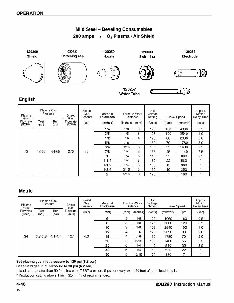
1/4 1/8 3 120 160 4060 0.5
3/8 1/8 3 125 100 2540 1.0
1/2 .16 4 125 80 2030 2.0
5/8 .16 4 130 70 1780 2.0
3/4 3/16 5 135 55 1400 2.5
7/8 1/4 6 135 45 1140 2.5
1 1/4 6 140 35 890 2.5
1-1/4 1/4 6 150 22 560 *
1-1/2 1/4 6 155 15 380 *
1-3/4 5/16 8 165 10 250 *
2 5/16 8 170 7 180 *
Shield Gas
PressureMaterial
Thickness
Arc Voltage Setting
Approx. Motion
Delay Time
Test (bar)
Run (bar)
(bar) (mm) (mm) (Inches) (Volts) (mm/min) (ipm) (sec)
6 3 1/8 120 4060 160 0.5
8 3 1/8 125 3000 120 0.5
10 3 1/8 125 2540 100 1.0
12 4 .16 125 2030 80 2.0
15 4 .16 130 1780 70 2.0
20 5 3/16 135 1400 55 2.5
25 6 1/4 140 890 35 2.5
32 6 1/4 150 560 22 *
50 8 5/16 170 180 7 *
English
Plasma Gas
Flowrate (SCFH)
Plasma Gas Pressure
Shield Gas
Flowrate (SCFH)
Torch-to-Work Distance Travel Speed
72 48-52 64-68 270 60
Metric
Plasma Gas
Flowrate (l/min)
Plasma Gas Pressure Shield
Gas Flowrate (l/min)
Torch-to-Work Distance Travel Speed
34 3.3-3.6 4.4-4.7 127 4.0
Mild Steel – Beveling Consumables
200 amps • O2 Plasma / Air Shield
Set plasma gas inlet pressure to 120 psi (8.3 bar)
Set shield gas inlet pressure to 90 psi (6.2 bar)
If leads are greater than 50 feet, increase TEST pressure 5 psi for every extra 50 feet of torch lead length.
* Production cutting above 1 inch (25 mm) not recommended.
120257
Water Tube
120833
Swirl ring
120258
Electrode
120259
Nozzle
020423
Retaining cap
120260
Shield