
Customer Upgrade Procedure Adding an optional 2.5-inch · PDF file... order new parts, and...
11
Customer Upgrade Procedure EMC Unity ™ Family EMC Unity ™ All Flash and EMC Unity ™ Hybrid Adding an optional 2.5-inch disk drive 302-002-592 REV 01 May, 2016 This document describes how to add an optional 2.5-inch disk drive in the Unity 300/300F, Unity 400/400F, Unity 500/500F, and Unity 600/600F. The drive slots are located behind the front bezel of the enclosure. These enclosures use 2.5-inch drives: l 25-slot disk processor enclosure (DPE) l 25-slot disk-array enclosure (DAE) Note The drive carriers for the 2.5-inch drive in the DPE can be transferred into the 25-slot DAE. Note You do not have to power down any components to add a new disk drive. NOTICE When Data at Rest Encryption is enabled, only drives that meet at least one of these requirements can be used: factory new drives, securely erased/sanitized drives, or previously encrypted drives. l Before you start ..........................................................................................................2 l Summary of tasks for adding a disk ............................................................................7 l Adding the new 2.5-inch disk drive ............................................................................ 8 l Verifying the operation of the 2.5-inch disk drive ..................................................... 10
Transcript of Customer Upgrade Procedure Adding an optional 2.5-inch · PDF file... order new parts, and...

Customer Upgrade Procedure
EMC Unity™ Family
EMC Unity™ All Flash and EMC Unity™ Hybrid
Adding an optional 2.5-inch disk drive302-002-592REV 01
May, 2016
This document describes how to add an optional 2.5-inch disk drive in the Unity 300/300F,Unity 400/400F, Unity 500/500F, and Unity 600/600F.
The drive slots are located behind the front bezel of the enclosure. These enclosures use2.5-inch drives:
l 25-slot disk processor enclosure (DPE)
l 25-slot disk-array enclosure (DAE)
Note
The drive carriers for the 2.5-inch drive in the DPE can be transferred into the 25-slot DAE.
Note
You do not have to power down any components to add a new disk drive.
NOTICE
When Data at Rest Encryption is enabled, only drives that meet at least one of theserequirements can be used: factory new drives, securely erased/sanitized drives, orpreviously encrypted drives.
l Before you start..........................................................................................................2l Summary of tasks for adding a disk............................................................................7l Adding the new 2.5-inch disk drive............................................................................ 8l Verifying the operation of the 2.5-inch disk drive..................................................... 10

Before you startBefore you begin this procedure, ensure that you have received the new part and havecorrectly identified its intended location in the system. Refer to your Unisphere Servicesection for instructions on how to identify failures, order new parts, and handle hardwarecomponents.
Additional resourcesAs part of an effort to improve its product lines, EMC periodically releases revisions of its software and hardware.Therefore, some functions described in this document might not be supported by all versions of the software orhardware currently in use. The product release notes provide the most up-to-date information on product features.Contact your EMC technical support professional if a product does not function properly or does not function asdescribed in this document.
Where to get helpSupport, product, and licensing information can be obtained as follows:
Product informationFor product and feature documentation or release notes, go to Unity TechnicalDocumentation at: www.emc.com/en-us/documentation/unity-family/index.htm. Youcan also access this page from the Unity product family page at: www.emc.com/en-us/storage/unity.htm. In the Why Unity section, click Unity Product Resources.
TroubleshootingFor information about EMC products, software updates, licensing, and service, go to EMCOnline Support (registration required) at: https://Support.EMC.com. After logging in,locate the appropriate Support by Product page.
Technical supportFor technical support and service requests, go to EMC Online Support at: https://Support.EMC.com. After logging in, locate Create a service request. To open a servicerequest, you must have a valid support agreement. Contact your EMC SalesRepresentative for details about obtaining a valid support agreement or to answer anyquestions about your account.
Special notice conventions used in this documentEMC uses the following conventions for special notices:
DANGER
Indicates a hazardous situation which, if not avoided, will result in death or seriousinjury.
WARNING
Indicates a hazardous situation which, if not avoided, could result in death or seriousinjury.
CAUTION
Indicates a hazardous situation which, if not avoided, could result in minor or moderateinjury.
Customer Upgrade Procedure
2 EMC Unity All Flash and EMC Unity Hybrid Customer Upgrade Procedure

NOTICE
Addresses practices not related to personal injury.
Note
Presents information that is important, but not hazard-related.
Handling replaceable unitsThis section describes the precautions that you must take and the general proceduresthat you must follow when removing, installing, and storing any replaceable unit.
Avoiding electrostatic discharge (ESD) damage
When replacing or installing hardware units, you can inadvertently damage the sensitiveelectronic circuits in the equipment by simply touching them. Electrostatic charge thathas accumulated on your body discharges through the circuits. If the air in the work areais very dry, running a humidifier in the work area will help decrease the risk of ESDdamage. Follow the procedures below to prevent damage to the equipment.
Be aware of the following requirements:
l Provide enough room to work on the equipment.
l Clear the work site of any unnecessary materials or materials that naturally build upelectrostatic charge, such as foam packaging, foam cups, cellophane wrappers, andsimilar items.
l Do not remove replacement or upgrade units from their antistatic packaging until youare ready to install them.
l Before you begin service, gather together the ESD kit and all other materials you willneed.
l Once servicing begins, avoid moving away from the work site; otherwise, you maybuild up an electrostatic charge.
l Use ESD anti-static gloves or an ESD wristband (with strap).If using an ESD wristband with a strap:
n Attach the clip of the ESD wristband to the ESD bracket or bare metal on acabinet/rack or enclosure.
n Wrap the ESD wristband around your wrist with the metal button against yourskin.
n If a tester is available, test the wristband.
l If an emergency arises and the ESD kit is not available, follow the procedures inEmergency Procedures (without an ESD kit).
Emergency procedures (without an ESD kit)
In an emergency when an ESD kit is not available, use the following procedures to reducethe possibility of an electrostatic discharge by ensuring that your body and thesubassembly are at the same electrostatic potential.
NOTICE
These procedures are not a substitute for the use of an ESD kit. Follow them only in theevent of an emergency.
Adding an optional 2.5-inch disk drive
Handling replaceable units 3

l Before touching any unit, touch a bare (unpainted) metal surface of the cabinet/rackor enclosure.
l Before removing any unit from its antistatic bag, place one hand firmly on a baremetal surface of the cabinet/rack or enclosure, and at the same time, pick up the unitwhile it is still sealed in the antistatic bag. Once you have done this, do not movearound the room or touch other furnishings, personnel, or surfaces until you haveinstalled the unit.
l When you remove a unit from the antistatic bag, avoid touching any electroniccomponents and circuits on it.
l If you must move around the room or touch other surfaces before installing a unit,first place the unit back in the antistatic bag. When you are ready again to install theunit, repeat these procedures.
Hardware acclimation times
Systems and components must acclimate to the operating environment before applyingpower. This requires the unpackaged system or component to reside in the operatingenvironment for up to 16 hours in order to thermally stabilize and prevent condensation.
Refer to the table, Table 1 on page 4, to determine the precise amount of stabilizationtime required.
Table 1 Hardware acclimation times (systems and components)
If the last 24 hours of theTRANSIT/STORAGEenvironment was this:
…and the OPERATINGenvironment is this:
…then let the system orcomponent acclimate inthe new environmentthis many hours:
Temperature Humidity
Nominal68-72°F (20-22°C)
Nominal40-55% RH
Nominal 68-72°F (20-22°C)40-55% RH
0-1 hour
Cold<68°F (20°C)
Dry<30% RH
<86°F (30°C) 4 hours
Cold<68°F (20°C)
Damp≥30% RH
<86°F (30°C) 4 hours
Hot>72°F (22°C)
Dry<30% RH
<86°F (30°C) 4 hours
Hot>72°F (22°C)
Humid30-45% RH
<86°F (30°C) 4 hours
Humid45-60% RH
<86°F (30°C) 8 hours
Humid≥60% RH
<86°F (30°C) 16 hours
Unknown <86°F (30°C) 16 hours
Customer Upgrade Procedure
4 EMC Unity All Flash and EMC Unity Hybrid Customer Upgrade Procedure

NOTICE
l If there are signs of condensation after the recommended acclimation time haspassed, allow an additional eight (8) hours to stabilize.
l Systems and components must not experience changes in temperature and humiditythat are likely to cause condensation to form on or in that system or component. Donot exceed the shipping and storage temperature gradient of 45°F/hr (25°C/hr).
l Do NOT apply power to the system for at least the number of hours specified in thetable, Table 1 on page 4. If the last 24 hours of the transit/storage environment isunknown, then you must allow the system or component 16 hours to stabilize in thenew environment.
Removing, installing, or storing replaceable units
Use the following precautions when removing, handling, or storing replaceable units:
CAUTION
Some replaceable units have the majority of their weight in the rear of the component.Ensure that the back end of the replaceable unit is supported while installing orremoving it. Dropping a replaceable unit could result in personal injury or damage to theequipment.
NOTICE
l For a module that must be installed into a slot in an enclosure, examine the rearconnectors on the module for any damage before attempting its installation.
l A sudden jar, drop, or even a moderate vibration can permanently damage somesensitive replaceable units.
l Do not remove a faulted replaceable unit until you have the replacement available.
l When handling replaceable units, avoid electrostatic discharge (ESD) by wearing ESDanti-static gloves or an ESD wristband with a strap. For additional information, refer to Avoiding electrostatic discharge (ESD) damage on page 3.
l Avoid touching any exposed electronic components and circuits on the replaceableunit.
l Never use excessive force to remove or install a replaceable unit. Take time to readthe instructions carefully.
l Store a replaceable unit in the antistatic bag and the specially designed shippingcontainer in which you received it. Use the antistatic bag and special shippingcontainer when you need to return the replaceable unit.
l Replaceable units must acclimate to the operating environment before applyingpower. This requires the unpackaged component to reside in the operatingenvironment for up to 16 hours in order to thermally stabilize and preventcondensation. Refer to Hardware acclimation times on page 4 to ensure thereplaceable unit has thermally stabilized to the operating environment.
Adding an optional 2.5-inch disk drive
Handling replaceable units 5

NOTICE
Your storage system is designed to be powered on continuously. Most components arehot swappable; that is, you can replace or install these components while the storagesystem is running. However, the system requires that:
l Front bezels should always be attached to ensure EMI compliance. Make sure youreattach the bezel after replacing a component.
l Each slot should contain a component or filler panel to ensure proper air flowthroughout the system.
Unpacking a partProcedure
1. Wear ESD gloves or attach an ESD wristband to your wrist and the enclosure in whichyou are installing the part.
2. Unpack the part and place it on a static-free surface.
3. If the part is a replacement for a faulted part, save the packing material to return thefaulted part.
Standard touch point colorsTouch points are component locations where you can:
l Grip the hardware to remove or install a component.
l Open or close a latch.
l Turn a knob to open, close, or adjust a component.
Standard touch point colors are terra-cotta (orange) or blue.
Note
Within this documentation, the color orange is used instead of terra-cotta for simplicity.
Table 2 Standard touch point colors
Touch point color Description
Terra-cotta(orange)
This color indicates that you can perform the task, such as remove acomponent with a terra-cotta (orange) lever, while the system remainspowered (up/on).
Note
Some tasks may require additional steps.
Blue This color indicates that a shutdown of the system or component isrequired before you can perform the task, such as removing a componentwith a blue lever.
Customer Upgrade Procedure
6 EMC Unity All Flash and EMC Unity Hybrid Customer Upgrade Procedure

Handling disksDisks are extremely sensitive electronic components. Always handle a disk gently, andobserve the following guidelines:
l Follow the instructions described in Removing, installing, or storing replaceableunits on page 5.
l Do not stack disks upon one another, or place them on hard surfaces.
l Make sure that the replacement disk has the same part number or the part number ofan approved replacement for the faulted disk. The part number (PN005xxxxxx)appears on the disk. A replacement disk should be the same type (example: SAS,FLASH) and have the same capacity (size and speed) as the disk it is replacing.
l When removing a disk, pull the disk partially out of the slot, then wait 30 seconds forthe drive to spin down before removing it.
l When installing multiple disks in a powered up system, wait at least 10 secondsbefore sliding the next disk into position.
l Place disks on a soft, antistatic surface, such as an industry-standard antistatic foampad or the container used to ship the disk.
Summary of tasks for adding a diskTo add a disk you must complete the tasks below in the order in which they appear. Thisdocument provides instructions for completing each task.
1. Open the console, if it covers the front of the enclosure to which you will add the disk.
2. Remove the front bezel from the enclosure.
3. Locate the slot for the new disk.
4. Remove the disk filler module from the slot for the new disk.
5. Unpack the new disk.
6. Install the new disk in the slot.
7. Reinstall the front bezel on the enclosure.
8. Close the console, if present.
9. Verify the operation of the new disk.
Adding an optional 2.5-inch disk drive
Handling disks 7

Adding the new 2.5-inch disk driveTake the following actions to install the new 2.5-inch disk drive into the system.
Locating a slot for a new diskLocate the slot with the disk filler module that you want to replace with the new disk.
Note
Unlike disks, disk filler modules do not have LEDs.
Removing a disk filler moduleProcedure
1. Insert your finger into the cutout on the bottom of the disk filler module (2).
2. With your thumb push in the latch on the top of the disk filler module, and pull themodule out of the slot (2).
Figure 1 Removing a disk filler module
CL5219
1 2
Unpacking a partProcedure
1. Wear ESD gloves or attach an ESD wristband to your wrist and the enclosure in whichyou are installing the part.
2. Unpack the part and place it on a static-free surface.
3. If the part is a replacement for a faulted part, save the packing material to return thefaulted part.
Customer Upgrade Procedure
8 EMC Unity All Flash and EMC Unity Hybrid Customer Upgrade Procedure
Installing a 2.5 inch diskBefore you begin
NOTICE
If you are installing multiple disks in a storage system that is powered up, wait at least 10seconds before sliding the next disk module into position.
Procedure
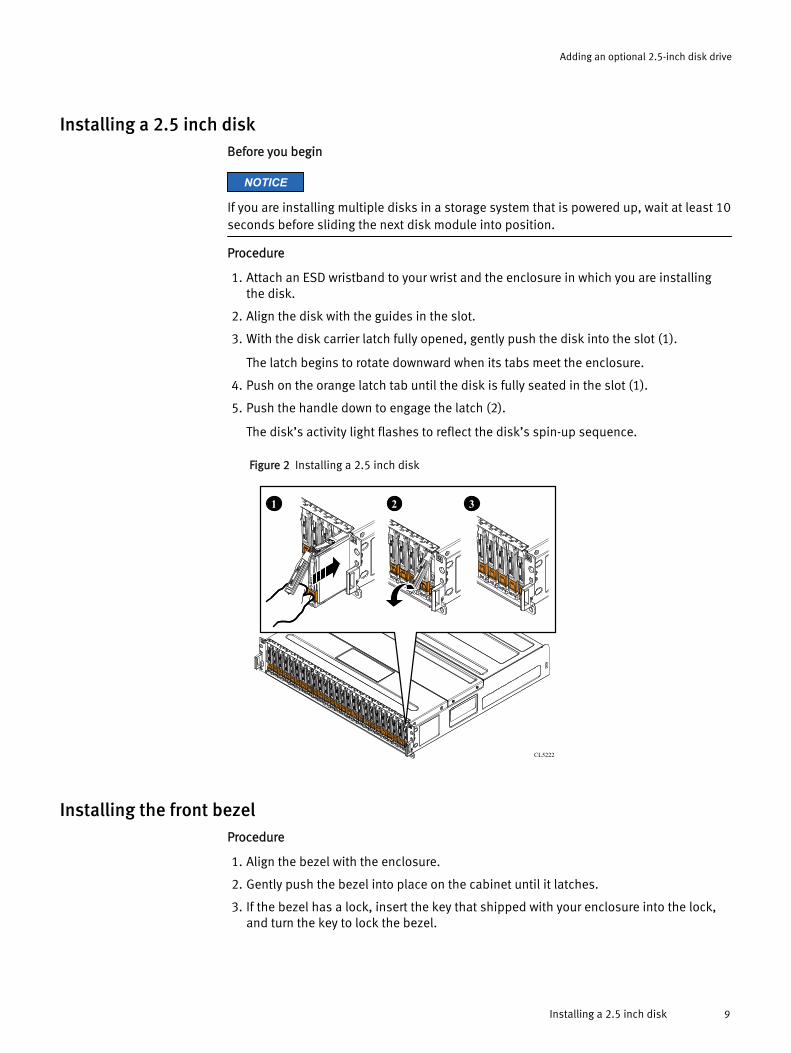
1. Attach an ESD wristband to your wrist and the enclosure in which you are installingthe disk.
2. Align the disk with the guides in the slot.
3. With the disk carrier latch fully opened, gently push the disk into the slot (1).
The latch begins to rotate downward when its tabs meet the enclosure.
4. Push on the orange latch tab until the disk is fully seated in the slot (1).
5. Push the handle down to engage the latch (2).
The disk’s activity light flashes to reflect the disk’s spin-up sequence.
Figure 2 Installing a 2.5 inch disk
CL5222
321
Installing the front bezelProcedure
1. Align the bezel with the enclosure.
2. Gently push the bezel into place on the cabinet until it latches.
3. If the bezel has a lock, insert the key that shipped with your enclosure into the lock,and turn the key to lock the bezel.
Adding an optional 2.5-inch disk drive
Installing a 2.5 inch disk 9
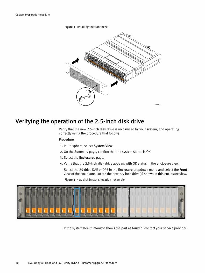
Figure 3 Installing the front bezel
CL5217
Verifying the operation of the 2.5-inch disk driveVerify that the new 2.5-inch disk drive is recognized by your system, and operatingcorrectly using the procedure that follows.
Procedure
1. In Unisphere, select System View.
2. On the Summary page, confirm that the system status is OK.
3. Select the Enclosures page.
4. Verify that the 2.5-inch disk drive appears with OK status in the enclosure view.
Select the 25-drive DAE or DPE in the Enclosure dropdown menu and select the Frontview of the enclosure. Locate the new 2.5-inch drive(s) shown in this enclosure view.
Figure 4 New disk in slot 8 location - example
If the system health monitor shows the part as faulted, contact your service provider.
Customer Upgrade Procedure
10 EMC Unity All Flash and EMC Unity Hybrid Customer Upgrade Procedure

Copyright © 2016 EMC Corporation. All rights reserved. Published in the USA.
Published May, 2016
EMC believes the information in this publication is accurate as of its publication date. The information is subject to change withoutnotice.
The information in this publication is provided as is. EMC Corporation makes no representations or warranties of any kind withrespect to the information in this publication, and specifically disclaims implied warranties of merchantability or fitness for aparticular purpose. Use, copying, and distribution of any EMC software described in this publication requires an applicable softwarelicense.
EMC², EMC, and the EMC logo are registered trademarks or trademarks of EMC Corporation in the United States and other countries.All other trademarks used herein are the property of their respective owners.
For the most up-to-date regulatory document for your product line, go to EMC Online Support (https://support.emc.com).
Adding an optional 2.5-inch disk drive
Verifying the operation of the 2.5-inch disk drive 11


