
Customer Installation Standards for Electric Service
103
CUSTOMER I NSTALLATION STANDARDS FOR ELECTRIC SERVICE September 4, 2018 A transition period will exist in which installations may be approved and connected as long as they meet either the 2013 or the 2018 editions. Beginning January 2, 2019, only the 2018 edition of the Customer Installation Standards will be accepted. This document is not copyrighted. Copying is encouraged. The latest edition is available at Entergy.com (See §1.3 for web address) New and changed information in italicized red
Transcript of Customer Installation Standards for Electric Service

CUSTOMER INSTALLATION STANDARDSFOR ELECTRIC SERVICE
September 4, 2018A transition period will exist in which installations may be approved and connected as long as
they meet either the 2013 or the 2018 editions. Beginning January 2, 2019, only the 2018edition of the Customer Installation Standards will be accepted.
This document is not copyrighted. Copying is encouraged.
The latest edition is available at Entergy.com (See §1.3 for web address)
New and changed information in italicized red
Summary of Major Changes from 2013 Edition
Sections
§1.5 Each required label/tag shall be permanently attached and not easily removed.
§2.3 No structures allowed over or under company facilities.
§3.4 House number and county/parish requirements added to Required Information for… Service.
§4.2.1 Removed typical electrical loads served by open and closed delta transformer installations.
§4.5 Customer shall provide required ground clearance for all temporary services.
§4.10 Changed section title to ‘High Rise Building Service’ with the requirement for customers to Consultthe Company for interior meter room locations.
§4.11 Service to Marinas… over Water shore to ship power shall meet the requirements of Section 4.13without the resistance grounded system, since single phase loads referenced internal to the vessel.
§4.13 Resistance Grounded Services allow neutral load an additional demand factor aligning with NEC.
§5.4 Voltages for Motors includes requirements for Contributions In Aid of Construction.
§7.2 Point of Attachment shall maintain separation between supply and communications cables.
§7.3 Higher clearances required for vehicles over 8 feet.
§8.9.1 Louisiana service areas require customer’s provide and install conduit for service cables.
§8.9.5.2 Removed subsection Rigid/Intermediate Metal Conduits
§8.9.5.4 “Minimum Conduit Guide…” removed Primary Conductors table and renumbered as §8.9.5.3.
§9.1.3 Meter Transformer Enclosure Specifications requires a locking mechanism suitable for a Companypadlock (handles with keys not acceptable) and clarified total customer conduit table.
§9.7.2 For Instrument Transformer Installation, when in the Company’s judgement the load does notexceed the capacity of a self-contained meter, the customer shall be responsible for the cost of anyadditional metering equipment.
§9.8.5 Alternate Sources… Transfer Systems specifies customer responsible for reserve capacity costs.
§12.5 Radio and Television Interference, Customer responsible for designing and operating theirequipment to FCC standards and avoid causing interference and damage to utilities/others equipment.
§15 Examples of Generators Interconnected to the Utility Grid include Fossil, Solar, Wind, Hydro,Geothermal, Biomass, Fuel Cell, Micro turbine, others
Drawings: Revised existing Drawing D7-4 added new Drawing D7-4A
2 of 1032018 Edition
Table of Contents
Foreword, General Information, and Terms ................................................. 7Section 1
Purpose ................................................................................................................................71.1Service Contracts, Terms and Conditions .....................................................................71.2Service Standards Availability and Revisions ..............................................................71.3How to Interpret and Apply the Standards ....................................................................81.4General Terms Used in Service Standards ....................................................................81.5Electrical Terms Used in Service Standards ............................................................... 131.6
Safety, Customer's Service Obligations and Protection .......................... 15Section 2
Safety .................................................................................................................................. 152.1Code Requirements ......................................................................................................... 152.2Distance Requirements for Customer Structures ...................................................... 162.3Working in Close Proximity to the Company's Facilities .......................................... 162.4OSHA Working Requirements ........................................................................................ 172.5Lightning and Other Surge Protection ......................................................................... 172.6Public Sign Clearance ..................................................................................................... 172.7Attachments to Company Poles .................................................................................... 182.8Right-of-Way for Service Facilities ................................................................................ 182.9Initial Clearing of Property for Right-of-Way ............................................................... 182.10Relocation of Company's Facilities............................................................................... 182.11
Information for Providing Electric Service ................................................. 19Section 3
Application for Service .................................................................................................... 193.1Pre-Installation Information ............................................................................................ 193.2Alterations to Existing Service (also see §5)............................................................... 193.3Required Information for New Service or Alteration to Service ............................... 203.4Connection of Service ..................................................................................................... 213.5
Types of Service .............................................................................................. 22Section 4
General Characteristics................................................................................................... 224.1Generally Available Types of Service ........................................................................... 224.2Availability of Three Phase Service .............................................................................. 234.3Facilities for Highly Fluctuating or Special Loads ..................................................... 234.4Temporary Service ........................................................................................................... 234.5Permanent Pole Services for Buildings, Structures, Mobile Homes and Travel Trailers ... 244.6Services for Mobile Home Parks ................................................................................... 244.7Central Service Poles or Load Center Distribution Pole for a Farmstead.............. 244.8Apartment Building Service ........................................................................................... 254.9High Rise Building Service ............................................................................................. 254.10Service to Marinas and Boat Docks/ Buildings Built over Water............................. 254.11Structure / house / raised or built elevated to avoid rising water ............................ 254.12
3 of 1032018 Edition

Resistance Grounded Services ..................................................................................... 254.13
Voltage Categories and Customer Equipment ........................................... 27Section 5
General Comments .......................................................................................................... 275.1Voltages for Lighting ....................................................................................................... 275.2Voltages for Heating, Instant Water heating units, and Car Chargers .................... 275.3Voltages for Motors.......................................................................................................... 275.4Voltages for Special Equipment .................................................................................... 285.5Voltages for Loads Served from Network Area .......................................................... 285.6
This Section Reserved for Future Use ......................................................... 29Section 6
Overhead Service ............................................................................................ 30Section 7
General Comments .......................................................................................................... 307.1Point of Attachment ......................................................................................................... 307.2Clearances ......................................................................................................................... 317.3Length of Service Drop ................................................................................................... 317.4Method of Attachment ..................................................................................................... 327.5Extension of Overhead Distribution Facilities ............................................................ 327.6480 Volts Metered Service .............................................................................................. 327.7
Underground Services and Installations..................................................... 33Section 8
General Comments .......................................................................................................... 338.1Ownership of Facilities .................................................................................................... 338.2Initial Clearing of Property for Service ......................................................................... 338.3Requirements for Obtaining Underground Service ................................................... 338.4Junction Box Requirements ........................................................................................... 358.5Underground Service from an Underground Network ............................................... 378.6Underground Electric Service for Mobile Homes ....................................................... 378.7Underground Electric Service for Mobile Home Parks .............................................. 378.8Conduit ............................................................................................................................... 378.9Termination of Customers’ Conductors in Company’s Transformers ................... 398.10Metering for Underground Service ................................................................................ 408.11Transformers Used in Underground Installations ...................................................... 408.12
Metering Installations and Equipment ......................................................... 41Section 9
General Comments .......................................................................................................... 419.1Meter Connections and Seals ........................................................................................ 439.2Meter Clearance ................................................................................................................ 439.3Location of Meter Installations ...................................................................................... 439.4Grouping of Meters .......................................................................................................... 449.5Meter Mounting Height .................................................................................................... 449.6Types of Meter Installations ........................................................................................... 459.7Disconnecting Means for Services Less Than 600 Volts .......................................... 479.8
4 of 1032018 Edition

Transformers, Vaults and Substations.................................................... 49Section 10
General Comments .......................................................................................................... 4910.1Access, Fences, Screen Walls, Decorative Walls....................................................... 4910.2Types of Transformer Installations ............................................................................... 4910.3Pad Mount Transformers ................................................................................................ 5010.4Transformer Vaults .......................................................................................................... 5010.5Termination of Secondary Conductors to Transformers for Non-Residential Services..... 5010.6
Customer’s Motors & Capacitors ............................................................. 51Section 11
General Comments .......................................................................................................... 5111.1Motor - Voltage Rating ..................................................................................................... 5111.2Motor Starting ................................................................................................................... 5211.3Critical Service Motor Operation ................................................................................... 5411.4Motor Protection ............................................................................................................... 5411.5Converters - Operation of Three Phase Motors from Single Phase Electric Supply .......... 5411.6Customer’s Capacitors and Other Reactive Equipment ........................................... 5511.7
Customer’s Special Equipment ................................................................ 56Section 12
General Comments .......................................................................................................... 5612.1Customer’s Sensitive Equipment .................................................................................. 5612.2Antennae & Dishes........................................................................................................... 5612.3CATV and Carrier Installations ...................................................................................... 5612.4Radio and Television Interference ................................................................................ 5712.5Facilities for Highly Fluctuating or Special Loads ..................................................... 5712.6
Arc Flash ....................................................................................................... 58Section 13
Consumer Owned Generators (not connected to utility) ..................... 59Section 14
General ............................................................................................................................... 5914.1Electrical Emergency or Standby Systems not connected ...................................... 5914.2Permanently Installed Generators (not connected to utility) ................................... 5914.3Temporary Connection of Emergency Generators .................................................... 5914.4
Generators Interconnected to and Operating in Parallel with the Utility Grid.......... 60Section 15
Power Quality Parameters for Customer Equipment Specifications 61Section 16
Drawings for 2018 Customer Installation Standards ..................................................... 62
5 of 1032018 Edition

This page intentionally left blank.
6 of 1032018 Edition

Foreword, General Information, and TermsSection 1Purpose1.1
The information contained in this book is presented for use in planning electrical wiring andapparatus installations intended for connection to the Entergy distribution power lines. Currentprocedures, practices and requirements, adopted by the Entergy companies to assureeconomical and satisfactory service to Customers, consistent with the most recent version ofthe National Electrical Safety Code (NESC), are set forth and discussed herein. (Note: Anystatement concerning the National Electrical Code (NEC) refers to Customer owned facilities.)Any mention of the NESC or the NEC indicates the basic provisions that are considerednecessary for safety. To the extent that Entergy's standards are more stringent than provisionsof the NESC or NEC, Entergy's standards must be satisfied. This book is limited to informationconsidered essential in planning installations which are adequate and satisfactory for the manyuses and conveniences of electric service. If the total service requested is over 200 Amps,other than 120/240 volts single phase or requires more than one meter contact the Company.
Service Contracts, Terms and Conditions1.2The following documents are not included in the Service Standards:
1. Service Regulations (or Terms and Conditions) which prescribe the rules, obligations,and liabilities of the Company in providing service and the Customer in receiving electricservice;
2. Rate Schedules (or tariffs) which set forth the price, periods of taking, and paymentterms for electric service;
3. Service Agreements wherein the Customer and the Company agree to specificquantities and type of service.
The Company’s currently approved Service Regulations, Rate Schedules, Service Agreements,and other forms are available by contacting the Company. The Customer should contact theCompany early in the design phase of a project for information concerning the terms andconditions of service.
Service Standards Availability and Revisions1.3The Service Standards are issued in an electronic format located at Entergy.com or a utilitywebsite below:
Arkansas: http://www.entergy-arkansas.com/your_business/builder.aspx
Louisiana: http://www.entergy-louisiana.com/your_business/builder.aspx
Mississippi: http://www.entergy-mississippi.com/your_business/builder.aspx
New Orleans: http://www.entergy-neworleans.com/your_business/builder.aspx
Texas: http://www.entergy-texas.com/your_business/builder.aspx
7 of 1032018 Edition

Another important reference is the Power Quality Standards for Electric Service which is at thesame location on the Entergy web page.
These Service Standards will be revised as new methods, improved equipment becomeavailable and codes change. Changes of policy made after the publication date, will be in effectdespite the fact that they will not be in the document. These changes of policy will be availableupon request. If the issue date is not the current year, contact the Company or go to thewebsite to determine if yours is the current edition or to obtain supplementary information. Toacquire the Service Standards in a book go to the website and print.
How to Interpret and Apply the Standards1.4When reading the standard, check out the key words (verbs):
Shall: A rule using the word “shall” is strictly enforced.
Should: A rule using “should” carries the idea that options exist, but that the rule contains thebest engineering expertise as written. This rule could be less strictly enforced than the “shall”rule.
Recommend: A rule using “recommend” has several options, but the Company would like forthe customer to use the one given. “Recommend” is never used where safety is an issue.
Ahead of the meter: The Company side of the meter also called the supply or line side
Behind the meter: The Customer side of the meter also called demand side or load side
General Terms Used in Service Standards1.5Agreement for Service: See "Application".
Application (or Agreement for Service or Contract): The agreement between the Companyand the Customer under which service is taken. Until a written agreement for service has beensigned, service rendered by the Company is subject to the provisions of the Company's ServiceRegulations and applicable rate schedule. The provisions of the Company's standardapplication for service will be presumed to apply. The supplying and taking of such service shallconstitute an Agreement for Service.
The American National Standards Institute (ANSI): The private non-profit organization thatoversees the development of voluntary consensus standards for products, services, processes,systems, and personnel in the United States. The organization also coordinates U.S. standardswith international standards so that American products can be used worldwide.
Authorities (having jurisdiction) (AHJ): The organization, office, or individual responsible forapproving equipment, materials, an installation, or a procedure. The basic role of an AHJ is toverify that an installation complies with the National Electrical Code.
Business Day: excludes weekends, Holidays and extreme weather events.
Company: Entergy Corporation, its operating subsidiaries, officers, agents or employees.
8 of 1032018 Edition

Company Designated Underground Areas: Those portions of the Company's service area,defined by the Company, where overhead service is not available. This includes concentrationsof commercial buildings with large loads that are not practical to serve with overhead facilities.
Company's Installation: In general, all the wires, devices, or apparatus on the Company'sside of the point of delivery. Some equipment, such as devices installed for metering electricconsumption or for demand side management, may belong to the Company, yet be installed onCustomer's side of the point of delivery.
Company Pole: Includes Company owned poles and poles occupied by the Company underjoint use agreements.
Conduit System: Any combination of duct, conduit, conduits, manholes, handholds, and vaultsjoined to form an integrated whole.
Contract: See "Application".
Customer: An individual, firm, partnership, association, corporation, organization, orgovernmental agency who is taking service as defined by regulatory authorities. Also refers tothose acting on Customer’s behalf (e.g. Architects, Builders, Contractors, Developers,Engineers, Electricians, etc.)
Customer's Installation (Premise Wiring): In general, all the wires, appliances, devices orapparatus of any kind or character on the Customer's side of the point of delivery except themeters, metering devices and facilities of the Company that may be located on the Customer'sside of the point of delivery. The Customer's wiring and electrical equipment within or on thepremises shall be installed and maintained in accordance with all effective building and wiringcodes, and local laws and ordinances.
Demand: The kW or kVA, as shown or computed from the readings of the Company's demandmeter installation, for the interval of the customer's greatest use between readings. (This is alsoknown as maximum demand.)
9 of 1032018 Edition
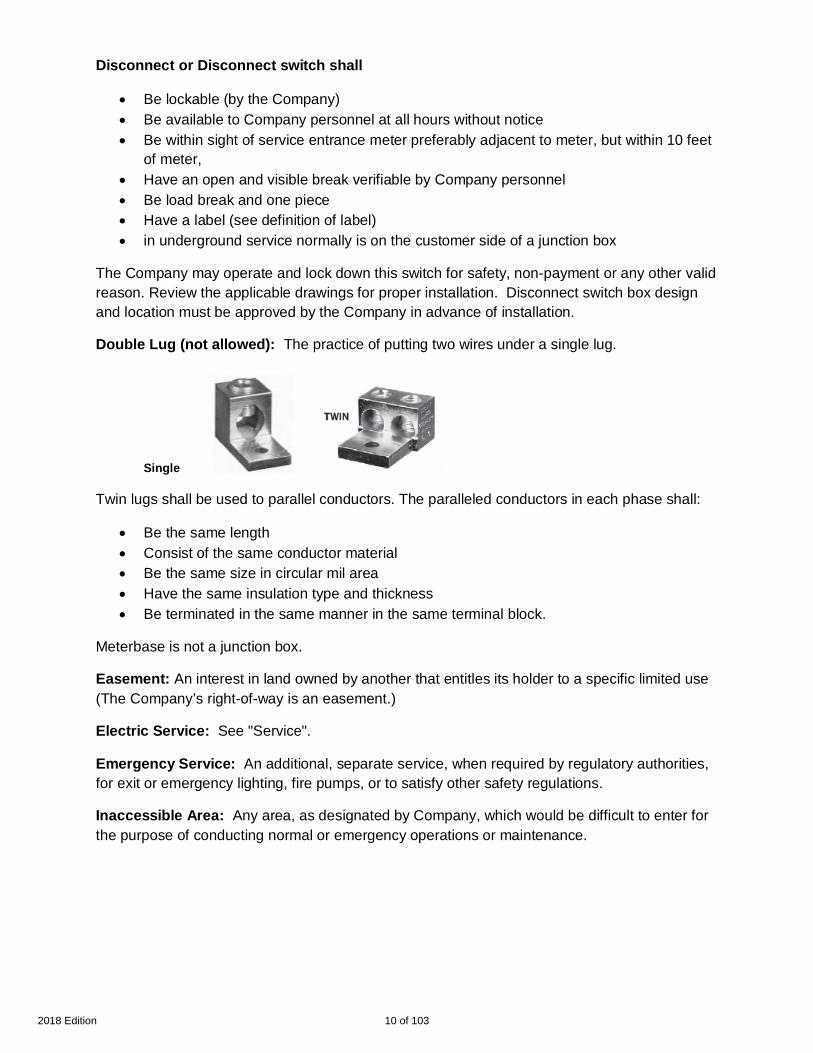
Disconnect or Disconnect switch shall
· Be lockable (by the Company)· Be available to Company personnel at all hours without notice· Be within sight of service entrance meter preferably adjacent to meter, but within 10 feet
of meter,· Have an open and visible break verifiable by Company personnel· Be load break and one piece· Have a label (see definition of label)· in underground service normally is on the customer side of a junction box
The Company may operate and lock down this switch for safety, non-payment or any other validreason. Review the applicable drawings for proper installation. Disconnect switch box designand location must be approved by the Company in advance of installation.
Double Lug (not allowed): The practice of putting two wires under a single lug.
Single
Twin lugs shall be used to parallel conductors. The paralleled conductors in each phase shall:
· Be the same length· Consist of the same conductor material· Be the same size in circular mil area· Have the same insulation type and thickness· Be terminated in the same manner in the same terminal block.
Meterbase is not a junction box.
Easement: An interest in land owned by another that entitles its holder to a specific limited use(The Company’s right-of-way is an easement.)
Electric Service: See "Service".
Emergency Service: An additional, separate service, when required by regulatory authorities,for exit or emergency lighting, fire pumps, or to satisfy other safety regulations.
Inaccessible Area: Any area, as designated by Company, which would be difficult to enter forthe purpose of conducting normal or emergency operations or maintenance.
10 of 1032018 Edition

Label: When permanently attached tags or labels are required, they shall be red backgroundwith white letters and UV resistant. The lettering on each label/tag shall be 3/16 inch or largerand be either raised or incised on each tag. Each tag shall be permanently attached to themeter loop or switch and not easily removed.
For Net Metering, interconnection customer shall label meter.
For Multiple Service drops to the same building more than 10 feet apart, Customer shall labeleach service drop’s meter-socket with an arrow pointing to other service drop meter(s) and adescription of the location (Examples: Service #1 Suite 10 located at northeast corner ofbuilding, Service #2 Suite 20 located at southwest corner of building)
For multiple meters, the meter enclosures and disconnects shall be labeled with suite orapartment identification.
For 480 volt services the disconnect ahead of the meter shall be labeled utility disconnect
In areas where cable can be owned by Company or Customer, for Customer owned cable,Customer supplied label shall say “Customer owned cable” (two required). One label shall beinstalled by Customer on meter socket; one label shall be given to Company for installation onthe transformer.
Consult the Company.
Load: The amount of electric power delivered or required at any specified point or points on asystem.
Mandatory Rules: The rules of the Service Standards which are characterized by the use ofthe word "shall."
Meter: A device or devices together with auxiliary equipment used for measuring any of thefollowing: apparent, real, and reactive power and/or energy, which are supplied to any customerat a single point of delivery.
Mobile Home or Trailer Park: A continuous parcel of land that is used for the accommodationof five or more occupied mobile homes or trailers with individually metered service and itsaccessory buildings or structures for the exclusive use of its occupants or owners. A parcel is aunit of land under unified ownership (with or without buildings).
National Electrical Code (NEC): The code adopted by the National Fire ProtectionAssociation, Inc (NFPA) and American National Standards Institute (ANSI) as advisoryinformation on the installation of electric facilities on private property. It is offered for the use inlaw and regulatory purposes in the interest of life and property protection.
National Electrical Safety Code (NESC): The code adopted by the Institute of Electrical andElectronics Engineers, Inc. (IEEE) and the American National Standards Institute (ANSI) inorder to bring consistency and safety to the design, construction, operation and use of electricsupply and communications installations.
11 of 1032018 Edition
Network Areas: Those designated portions of the Company's service area which includeconcentrations of commercial buildings, and which are typically supplied by a secondarynetwork underground distribution system.
Point of Delivery: (also called “Point of Common Coupling) The physical locationdesignated/approved by the Company where the Customer's service terminals or wires arejoined to the Company's facilities.
Power Quality Standard for Electric Service: This Standard describes the Power Qualityrequirements of Entergy. The Power Quality Standard for Electric Service is issued in anelectronic format on the Entergy web page. See §1.3 for web links.
Public Property: Property dedicated to public use such as streets, alleys, canals, roadways,and highways. This does not include schools, parks, public housing, gyms, playgrounds, publicbuildings, etc., which are considered customer premises.
Rigid Metal Conduit: A raceway specially constructed for the purpose of the pulling in or thewithdrawing of wire or cable after the conduit is in place and made of metal pipe of standardweight and thickness permitting the cutting of standard threads.
Rigid Non-metallic Conduit: Gray polyvinyl chloride (PVC), schedule 80 or schedule 40, tubefor enclosure of electrical wires and cables which includes associated equipment such asadapters, cable enclosures, couplings, junction boxes, pull boxes, etc., as required for acomplete enclosure system. (Schedule 80 PVC shall be manufactured per NEMA TC-2standard.)
Service (or Electric Service): The availability of electric power and energy to the Customer,regardless of whether any power and energy is actually used. Supplying of service by theCompany consists of its maintaining at the point of delivery the approximate nominal voltageand frequency by means of facilities adequate for supplying the Customer's contracted load.
Service Conductors: The supply conductors that extend from the street main or fromtransformers to the service equipment of the premises supplied.
Service Drop: The overhead service conductors from the last pole or other aerial support toand including the splices, if any, connecting to the service-entrance conductors at the building orother structure;
Service Entrance: The Customer owned equipment for connecting to the service conductorsor the service entrance conductors.
12 of 1032018 Edition
Service Entrance Conductors:
Overhead System: The service conductors between the terminals of the service equipment anda point usually outside the building, clear of building walls, where it is joined by tap or splice tothe service drop.
Underground System: The service conductors between the terminals of the service equipmentand the point of connection to the service lateral.
Shall: The highest degree of requirement, no other options exist when shall is used. (Also see1.4)
Type of Service: The electrical or physical attributes of the service such as voltage, phase,frequency, transformer connection, number of wires, overhead or underground installation, etc.
Underground Service: The underground cable installation which connects the Company'sdistribution system to the Customer's service entrance conductors, or to the line side lugs of themeter socket.
Electrical Terms Used in Service Standards1.6Ampere: The unit of measurement of the rate of flow of electricity. It is the unit of currentproduced in a circuit by one volt acting through a resistance of one ohm.
Btu (British Thermal Unit): The quantity of heat required to raise the temperature of onepound of water one degree Fahrenheit. Capacity of air conditioning, heating, or heat content offuel, etc. is measured in Btu. Btu/h is the rate of heat change - Btu per hour.
Current: The rate of flow of electricity usually measured in amperes. The Company suppliesalternating current (AC) and will not supply direct current (DC).
Energy: The total work done as distinguished from the rate of doing work (power), usuallymeasured in kilowatt-hours. Its amount depends upon the power and the time that the power istaken. For instance, a power rate of one kilowatt maintained for one hour is one kilowatt-hour ofenergy.
Hertz: Unit of frequency in Cycles per second For example, the Company furnishes 60 Hertzalternating current.
Horsepower: A unit of power, equal to a rate of 33,000 foot pounds of work per minute.Motors are normally rated in horsepower to indicate the mechanical power they are designed toproduce. One horsepower equals 746 watts. Motors require 746 watts input, plus losses, foreach horsepower output.
Kilovolt-ampere: (kVA) 1,000 volt amperes, the unit of apparent power, volts times amperes,which is comprised of both real and reactive power.
Kilowatt: (kW) 1,000 watts.
13 of 1032018 Edition

Kilowatt-hour: (kWh) A quantity of electrical energy - equal to 1000 watts used continuouslyfor one hour, or 100 watts used continuously for ten hours, or some other equivalent.
Number of Phases: See "Phase".
Ohm: The unit of measurement of electrical resistance or impedance. It is that resistancethrough which one volt will produce a current of one ampere.
Phase (or Number of Phases): Term which designates characteristics of alternating current.It is a term used in the electric industry relating to the characteristics of the electrical serviceavailable or supplied at a given location or required for the operation of a given electrical device.Single phase is normally supplied for residences and small power customers and three phase issupplied for larger power customers.
Power: The time rate of doing work, generating, transferring, or using electric energy, usuallyexpressed in kilowatts (kW).
Power Factor: The ratio of real power (kW) to apparent power (kVA) for any given load andtime. Normally, power factor is expressed as a ratio and stated as a percentage.
Reactive-kilovolt-amperes: (kVAR) (rkVA) (kilovar) The product of the applied voltage and themagnetizing or charging current, divided by 1,000. Reactive-kilovolt-amperes do no work butmust be supplied to magnetic equipment, such as motors. Generators or capacitors supply it.
Sag (Voltage sag): A decrease in RMS voltage at the power frequency for duration of 0.5cycles to 1 minute. Typical values are 0.1 to 0.9 per unit.
Volt / Voltage: A unit of electrical pressure or potential or electromotive force which if appliedto a load of one ohm resistance will cause a current of one ampere to flow. Primary distributionand transmission voltages are usually designated in kilovolts (kV). One kilovolt is equal to 1,000volts.
Watt: An electrical unit of power. Electrical appliances and lamps are rated in watts to indicatetheir capacity or rate of using power for doing work. A 100 watt lamp used 10 hours will use onekilowatt-hour (kWh) of energy (1,000 watt-hours). Likewise a household iron rated at 1,000watts will use one kilowatt-hour in one hour.
14 of 1032018 Edition

Safety, Customer's Service Obligations and ProtectionSection 2Safety2.1
Safety is paramount. If the Company believes, based upon observation, information orexperience that danger to the public or to an individual exists, work shall stop until such dangeris remedied.
Code Requirements2.2
General2.2.1The data contained herein is intended to conform with and be supplementary to recognizedcodes or rules and regulations of the authority having jurisdiction over the installation. In allcases, those codes or rules and regulations shall govern, regardless of possible conflict in theexpressed or implied meaning of the contents of this book. The contents are intended to beconsistent with the principles of the NEC on the Customer's side of service and consistent withthe NESC on the Company side. Compliance with the requirements of the NEC will provide theCustomer with what is considered a standard for appropriate use of electricity. Any differencefrom the NEC is intended to provide better service than required by the standards of theCode.
Inspection and Approvals2.2.2The wiring, electrical equipment and appliances of the Customer should be installed inaccordance with the requirements of the latest NEC and of authorities having jurisdiction. TheCompany does not inspect Customer premise wiring. Where inspection is available, theCompany requires the Customer to have the premise wiring inspected and approved by theauthorities having jurisdiction before requesting connection to the Company's service. Whereinspection is required, the Company is not allowed to connect to the Customer's installation untilit has been inspected and approved by the authorities having jurisdiction
The Company reserves the right to refuse connection to any new installation and/or todisconnect from any existing service, should the Company learn that the wiring is unsafe or thatit has not been approved. The authorities having jurisdiction also have the right to require theCompany by written notification to discontinue service to an installation which has been foundunsafe. The Company is not liable for any damages incurred when electrical service isdiscontinued under order of the authorities having jurisdiction. The Company accepts noresponsibility for injury or damage to the Customer's premises or to persons on the Customer'spremises resulting from defective wiring or equipment.
Grounding of Service Equipment2.2.3The identified neutral conductor and metallic parts of the service equipment, including all metersockets, and instrument transformer enclosures, shall be effectively grounded. All groundingshall be bonded together.
A driven ground rod is preferred by Company and is shown in drawings in §7 (OverheadServices) and §8 (Underground Services).
15 of 1032018 Edition

The Company reserves the right to refuse installation of service contingent upon inspection ofCustomer’s grounding connections.
Grounding requirements are shown on many of the drawings in the Customer InstallationStandards.
A grounding conductor (#6 CU minimum – refer to NEC for correct sizing) that is free fromexposure to physical damage shall be permitted to be run along the surface of the buildingconstruction without metal covering or protection where it is securely fastened to theconstruction; otherwise, it shall be in conduit, electrical metallic tubing, or cable armor.
All metal buildings, metal structures, and metal siding on buildings to which electric service is tobe supplied shall be permanently bonded to the service entrance ground before service isconnected.
Bracing of Poles or Risers2.2.4Bracing is required if a pole or riser:
· Is unstable,· Bends,· Moves when shaken· Moves when a ladder is put against it· Moves when the lineman gets on the ladder, or· Bends when wires are attached.
Consult the Company for specific requirements. See Drawing D2-1
Distance Requirements for Customer Structures2.3The construction of any structure near, under or over electrical facilities can cause a code and /or safety violation and be an encroachment on Company right of way. No structures allowedover or under company facilities. Consult the Company concerning all clearances.
Permanent or temporary structures shall never be located within 10 feet (measured horizontally)of the Company’s aboveground electrical facilities.
The Company will not allow the placement of electrical service near, over or under a pool norpermit the construction of a pool over or under electrical facilities.
Working in Close Proximity to the Company's Facilities2.4Customers should use extreme caution to avoid contact when working in the proximity of theCompany's overhead or underground conductors or other electric facilities to prevent injury andto prevent damage to either the Company's or the Customer's equipment. State Law prohibitsunauthorized persons from working, including moving equipment, within ten feet of distributionoverhead electric utility line.
Work shall be performed only after satisfactory mutual arrangements have been completedbetween the owner or operator of the high voltage overhead electric utility line and the personresponsible for the work to be done.
16 of 1032018 Edition

To notify Company that you intend to work within ten feet of a distribution overhead electricutility line owned or operated by it, please call 1-800-ENTERGY (1-800-368-3749) not less thantwo business days prior to commencing work. Please note Transmission level voltage requiregreater clearance.
In locations with underground facilities, the Customer shall notify One Call at 811 not less thantwo business days prior to commencing work and shall have One Call locate all undergroundfacilities before digging. It shall be the responsibility of the Customer to stay clear of all electricfacilities.
OSHA Working Requirements2.5OSHA requires that all operators of equipment maintain a minimum of 10 feet of radialclearance from energized electrical facilities. Please note Transmission level voltage requiresgreater clearance.
Lightning and Other Surge Protection2.6Surge arrester protection is recommended by the Company. Customer surge protectionequipment shall:
· be installed behind the meter, past the disconnect, and· not be connected to:
o meter socketso service drop conductors,o service entrance conductors.
Customers installing surge arresters should consult applicable codes, a licensed, professionalengineer or electrician, or the manufacturer of protective equipment.
Refer to §16 for Power Quality Parameters for Customer Equipment Specifications andEntergy’s Power Quality Standard for Electric Service
Public Sign Clearance2.7Clearances of signs from conductors shall meet or exceed the clearance requirements set forthin the National Electrical Safety Code.
17 of 1032018 Edition

Attachments to Company Poles2.8Attachments to Company poles are normally not allowed. Attachments shall be made only withapproval of the Company. If an attachment is allowed, an attachment agreement shall besigned, and the agreement will set forth any charges. All allowed attachments are to be madeunder the supervision and to the satisfaction of the Company. All allowed attachments shall bemade in accordance with the specifications of authorities having jurisdiction, where applicable.Consult the Company for details.
Right-of-Way for Service Facilities2.9The property owner(s) will grant, at no cost to the Company, right-of-way suitable to theCompany for the installation of the Company's facilities. The Company will provide a writtenright-of-way permit document for execution by the property owner(s). The Company may requirethe Customer's assistance in obtaining right(s)-of-way from adjacent property owner(s).
The Company shall also be provided, at no cost, written agreements covering propereasements if:
1. Primary facilities are installed on private property,2. Secondary facilities are to be installed on the Customer's premises that could serve one
or more Customers on adjoining properties,3. Facilities cross over or under private property, such as, cross country, adjoining
highways and roadways, within subdivisions, etc., and4. Facilities are constructed within the confines of a highway or roadway that exists by
virtue of servitude only.
All parties, i.e., in fee land owner(s), grantee(s), shall give their consent.
Initial Clearing of Property for Right-of-Way2.10The Customer requesting a new service is responsible for the cost of preparing the initial right-of-way. The Customer may perform the clearing as instructed by the Company on all propertyowned by the Customer. In areas where side trimming is needed after the Customer completesthe groundwork, the Company will trim only those trees the Customer cannot trim. TheCustomer shall be responsible for removal of all debris. At the Company's option, the Companymay clear the right-of-way and be reimbursed by the Customer. For additional details coveringunderground installations, refer to §8.3, Initial Clearing of Property for Service.
Relocation of Company's Facilities2.11The Company will move or relocate the Company's facilities where practical to do so at therequest of the Customer. The Customer may be required to provide consideration (i.e.,payment, furnishing of installed facilities, etc.) in exchange for the relocation.
18 of 1032018 Edition

Information for Providing Electric ServiceSection 3Application for Service3.1
Customers can apply for service online at Entergy.com or call 1-800-ENTERGY (1-800-368-3749).
Service rendered by the Company is subject to the provisions of the Company's ServiceRegulations and applicable rate schedule. The supplying and taking of such service shallconstitute an Agreement for Service if no written agreement for service or application for servicehas been executed.
Pre-Installation Information3.2Architects, Builders, Contractors, Developers, Engineers, Electricians, or Owners are requiredto consult the Company for information regarding the availability and type of service, andlocation of the service drop, service entrance, and meter.
The Company is not responsible for the cost of replacing any of the Customer’s facilities that donot meet the requirements for service. Connection to the Company's electric system is notavailable prior to approval by the Company. The approval process may include the acquisitionof permits and/or inspections by the authorities having jurisdiction. The service may be installedoverhead or underground depending on the Customer's preference and/or the facilities availablein the area of the premises to be served. Consult the Company.
Alterations to Existing Service (also see §5)3.3The Company's facilities, including meters, transformers, and other equipment, are sized andinstalled to satisfy the Customer's requirements at the time the service is initiated and is basedon information supplied by the Customer.
It is essential that the Customer give notice to the Company of any substantial additional load(e.g., a large motor) that is to be connected to the electric system. The Customer should notproceed to make these additions until after the Company has notified them that it can eithersupply the increased load or the conditions or under which the increased load can be served.The Customer may be required to pay for these changes. The Company is not liable forany damages incurred by the Customer connecting additional equipment without noticeto the Company.
Under no circumstances shall any service drop wire, meter or metering equipment belonging tothe Company be disconnected, removed, or relocated unless authorized by the Company. Thisauthorization requires advance notification. The Company may require the replacement of theCustomer's obsolete equipment at the service entrance or relocation of the service entrance toa more accessible area prior to providing the requested service.
The construction of pools, decks, fences or any structure near, under or over electricalfacilities may cause a code and / or safety violation. Consult the Company concerning allclearances.
19 of 1032018 Edition

Required Information for New Service or Alteration to Service3.4The Customer shall furnish the following information to Company for any new service, oralterations to existing service, desired by the Customer:
1. Exact location(s) of premises, including street address if available, where service isdesired.
2. 911 address if different than street address[Note: 911 address (house number) or other address if no 911 address is available shallbe posted near the location where the meter is to be installed.] A minimum 3” letteringmarked on meter enclosure, pole or durable material attached to pole and should bevisible from the street.
3. All locations must have street or road name and good directions to service location.4. Name of city and county/parish if service location is within an incorporated city limits.5. Billing address and name.6. Home phone, work phone and mobile phone if applicable.7. Permitting requirements, if any8. Type of service (including service voltage), equipment rating, and amount of electrical
load to be installed.9. Total motor load (to include size(s) of largest motor(s), starting current(s), NEMA letter or
code) and rated voltage.10. General characteristics of equipment to be driven by motors.11. Date new electric service or alterations to existing service are needed.12. Desired point of delivery or service entrance location and location of disconnect and/or
breaker box. Sketch or drawing may be required. Company maintains the right todesignate point of delivery.
For residential applications the Customer will be asked to provide both his or her social securitynumber and the place of employment, as well as the social security number and place ofemployment of their spouse or roommate.
The Company may refuse service for other than technical reasons. Also see §2.2.
The Company (or the Company's contractor) shall make the connection at the point of delivery.In special cases the Company may authorize and/or require the Customer's contractor to makethis connection. This authorization shall be obtained before any connections are made directlyto the electric system. This requirement does not preclude the Customer's contractor orelectrician from installing meter sockets, metering transformers, or other equipment whenfurnished by the Company.
The Customer shall install and maintain the Customer's wiring and electrical equipment within oron the premises, in accordance with building and wiring codes, laws and local ordinances thatare in effect.
20 of 1032018 Edition

Connection of Service3.5The Customer is required to contact the Company to schedule the connection of the service.The Company will schedule service connection after the authority having jurisdiction has notifiedthe Company all required permits and inspections are passed and approved.
If the main breaker or disconnect switch is outside, by the meter, the grounding conductor andconnections are identifiable and inspectable, the switch will be placed in the “off” position andthe meter installed. The switch will be left in the “off” position and the Customer shall beresponsible for putting the switch in the “on” position.
If no breaker or disconnect is available or the grounding conductor and connections cannot beidentified and/or inspected, a Customer who can and shall operate the inside switch and assistin the inspection of the grounding conductor and connections shall be present so the Companycan safely connect the meter. If that qualified Customer is not present, Company will notconnect the service. Customer will be required to contact Company to schedule a timeframewhen Customer can be present.
21 of 1032018 Edition

Types of ServiceSection 4General Characteristics4.1
The electric service furnished by the Company is 60 Hertz alternating current, single and threephase.
Generally Available Types of Service4.2The type of service (number of wires, phase, and voltage) furnished by the Company dependson two factors:
1. The voltage available near the service location.2. The type of service which in the Company's judgment can most economically be made
available to serve the nature, size, and location of the Customer's requirements.
A particular type of service may or may not be available at a given location.
Generally Available Standard Transformations of Electric Service4.2.1Types of Service Typical Loads Served
1. 1 phase - 120/240 volts – 3 wire Residential and other small loads
2. 3 phase delta - 120/240 volts - 4 wire
(Consult Company for availability on35 kV systems.)
Loads with both single and three phaserequirements not exceeding 1,000 kVA
3. 3 phase wye - 120/208 volts - 4 wire Three phase loads from 50 kVA to 1,000 kVA
4. 3 phase wye - 277/480 volts - 4 wire Loads between 75 kVA and 3,000 kVA
5. 3 phase wye - 2400/4160 volts - 4 wire Contact Company for minimum load requirements
6. Service voltages within network grids Refer to § 8.6
Notes:
· For specific information on voltage transformations, consult the Company or the rateschedules. Refer to Table 5.4 for allowable motor sizes for various voltages.
· Five wire service is prohibited. The neutral must be grounded at the meter enclosure orfor multiple services as shown in the drawings in this book.
· Three phase services are normally four wire. Customer is required to take the neutral tothe first disconnect switch past the meter. Consult the Company
· Does not include all types of service available. Contact the Company for furtherinformation on the availability of all distribution voltages not listed.
22 of 1032018 Edition

The following scenarios require the Customer to contact the Company online4.2.2at Entergy.com or call 1-800-ENTERGY in the planning stage to discussavailability, design, and costs.
1. Fire pumps, Emergency systems, and legally required standby systems services (whichshall be allowed separate additional service drops).
2. Different Characteristics (voltages, or phases, or for different uses, such as for differentrate schedules which may be allowed additional service drops.)
3. Very large services (>2000 amps may also qualify for an additional service drop.)4. Apartment Buildings and multiple service buildings (shall have the service grouped at a
single Company approved location. The exception is where a maximum two areas areseparated by a firewall and then a second service drop in a different Companyapproved area may be permitted. (Labels required see §1.5.))
5. Typically all of the service drops will be to the same place on a building. These servicesshall otherwise conform to the Standards.
Availability of Three Phase Service4.3The Company has many areas in which three-phase facilities are not available. Customer’s costmay be prohibitive in relation to the value of three-phase service. Customer should contact theCompany to determine if any charges are associated with the desired service prior to makingany decision concerning the purchase of electrical equipment.
Facilities for Highly Fluctuating or Special Loads4.4Highly fluctuating loads such as welders, X-ray machines, and motors with unusual or frequentstarting requirements may interfere with other Customers' electric service. See § 5.5
Temporary Service4.5The Company provides many types and classes of temporary service that may be available atthe location for construction work, traveling shows, etc. The Customer shall provide requiredground clearance and protective devices for all temporary services. Customer installed poles tobe used for temporary service shall be treated. Overhead temporary service poles are typicallyset no more than 75 feet from the nearest Company pole. For additional information see:
· Drawing D4-1 for a typical structure for temporary service from an overhead source· Drawing D4-2 for a typical structure for temporary service from an underground source.
The Company will specify the temporary service pole location for either overhead orunderground service.
Specific terms and conditions under which temporary service will be provided may be obtainedfrom the Company. When air conditioned or electrically heated construction trailers are to beserved please see §4.6 or consult the company.
23 of 1032018 Edition

Permanent Pole Services for Buildings, Structures, Mobile Homes and4.6Travel Trailers
Requirements for electrical service for individually located mobile homes and travel trailers differfrom other types of service. Provisions shall be made for connecting a mobile home feederassembly by a permanent wiring method. Customer feeder conductors shall consist of either afactory-installed listed cord or a permanently installed feeder consisting of four, insulated, colorcoded conductors. For information on the location of meter service, see Drawings D4-4 andD4-6.
For mobile homes installed in locations other than in a mobile home park, see Drawings D4-3and D4-4 for a typical meter service installation from an overhead source and Drawings D4-5and D4-6 for a typical meter service installation from an underground source.
Services for Mobile Home Parks4.7Mobile Home Parks are five or more mobile homes or trailers and accessory buildings on acontinuous parcel of land used by its occupants or owners. These parks shall be served at acommon point as shown in Drawings D4-8, D4-9 and D4-10. The park management shall beresponsible for running service from the disconnect beyond the 120/240 volt Entergy meter tothe individual trailers.
On overhead service from Entergy, Entergy shall have exclusive use of the pole where the pointof common connection is. Entergy recommends the Park use underground feeders to individualtrailers to avoid the hazards of tall trailers contacting electric lines. If the Park wishes todistribute the electricity overhead it must use a separate pole from the Entergy feed pole.Consult the NEC for overhead clearances and underground construction on Customer ownedlines.
Central Service Poles or Load Center Distribution Pole for a Farmstead4.8For farm and other Customers who have two or more points of utilization at contiguous locationsand where it is more practicable to deliver service at a central service pole on the Customer’sproperty than at a building, the Company will deliver service under the following conditions:
1. Central service pole will be installed, owned, and maintained by the Customer. Refer toDrawings D4-7.
2. No foreign objects such as television masts, bird boxes, etc. will be allowed on the pole.3. The Company will connect its service wires to the Customer's service entrance
conductors on the central pole, this point of connection being the point of delivery ofservice.
4. Customer will install service entrance (or meter loop) and fused switch or circuit breaker(all to be owned by the Customer) on central service pole.
5. The wires extending from the central service pole to the Customer's buildings or pointsof utilization will be a part of the Customer's installation and shall be installed andmaintained by the Customer.
24 of 1032018 Edition

Apartment Building Service4.9Where apartment buildings are contemplated, the Company should be contacted before plansare drawn, in order that adequate service can be made available to the prospective tenants.
High Rise Building Service4.10The Company will not install, own or maintain a vertical distribution system in high rise buildings.Service will be provided and the Customer shall pay to the Company according to theCompany’s policy. Consult the Company for interior meter room locations.
Service to Marinas and Boat Docks/ Buildings Built over Water4.11The Company will provide electric service to marinas and boat docks and buildings built overwater. These electric services shall terminate on land at a point above the expected high waterlevel designated by the Company. The height of the meter may be increased to accommodateflood plains. Accessibility for Company personnel is required see §9.6 Meter Mounting Heightregarding platforms needed. Consult the Company for the exact location and other details.
A disconnect switch shall be installed at the point of delivery. All underground servedinstallations will have a junction box before the disconnect as the point of delivery (see §8.5).With the exception of the meters, the Customer shall own, install, and maintain all facilitiesbeginning at the point of delivery. Meters will be owned by the Company but may be installednear each boat slip. Shore to ship power shall meet the requirements of Section 4.13 withoutthe resistance grounded system, since single phase loads are referenced internal to the vessel.
Structure / house / raised or built elevated to avoid rising water4.12See §9.6 Meter Mounting Height.
Resistance Grounded Services4.13A grounding resistor desired by the customer must be on the customer’s premises past the pointof delivery and preferably near the customer’s fault interrupting equipment. Company does NOTallow grounding resistors to be installed in Company padmount transformers. The followingrequirements must be satisfied:
1. The grounding straps on the padmount must be disconnected from the groundingbushing and folded down and out of the way for possible future use of the padmount ona grounded neutral installation.
2. A fully insulated neutral conductor, the same size as the secondary phase conductors,must be maintained from the neutral bushing to the point of delivery for the customer tocarry to the grounding resistor or directly to the shipboard service. Service neutral shallbe permitted to have an additional demand factor of 70 percent applied to the portion ofthe unbalance load in excess of 200 amperes.
3. There must be a clear and obvious label above the neutral bushing that says: STOP!DO NOT CONNECT “GROUND STRAP” --- Ungrounded Neutral and on the front of thepadmount, a label that says “CAUTION --- Ungrounded Neutral”.
4. If the point of delivery is at the padmount, the customer’s contractor must have four fullyinsulated conductors; one for each phase and one for the neutral.
25 of 1032018 Edition

5. Metering on the secondary side of the padmount must be line to neutral with twobushing PT’s to handle the neutral the same as a phase conductor. The meteringinstallation must be clearly labeled “CAUTION --- Ungrounded Neutral; do NOTconnect neutral to ground”.
6. The padmount transformer tank, metering enclosure or rack, and primary insulatedshielding conductors must be solidly grounded and isolated from the insulated neutralconductor.
26 of 1032018 Edition

Voltage Categories and Customer EquipmentSection 5General Comments5.1
Any type of service or voltage not defined as the Company's standard voltage may be suppliedonly after specific written approval is obtained from the Company.
Equipment operated at the Customer's service voltage should be designed for operation at thatvoltage.
Voltages for Lighting5.2The recommended service voltage for lighting is 120 volts. Customers served by highervoltages may use 208, 240, 277, or 480 volts for lighting. Where the lighting voltage is differentfrom the voltage supplied by the Company, the Customer will install and maintain suitabletransformers on the Customer's side of the point of delivery.
Voltages for Heating, Instant Water heating units, and Car Chargers5.3The recommended voltage for space and water heating, ovens and Car chargers is normally208 or 240 volts, depending on the service voltage. Higher voltages, as available, may be usedfor larger loads.
Units rated 30kVA or larger should be three phase. Prior to purchase of equipment, consult theCompany for service to units rated 15 kVA (60 amps) or higher, and when the newly addedunits bring the total load over 30 kVA. See §5.5 & §3.3.
Voltages for Motors5.4Consult the Company before commitments are made for all single phase motors over 6½ hp,three-phase motors over 30 hp and for any motor that may have requirements not suited for theavailable service near the Customer location.
Motors larger than 30 hp should typically be served with a three transformer bank or threephase padmount transformer and not an Open Wye – Open Delta bank. The customer may berequired to pay any additional cost required to provide this service, such as installing a thirdprimary phase. Motors with no service factor are more sensitive to small phase voltageunbalances and voltages below nominal.
Table 5.4 offers a general guide for selection of motor voltages for various horsepower ratings.
27 of 1032018 Edition

Table 5.4 General Guide for Service to Motors
Total Connected MotorLoad (hp)
Size of Largest IndividualMotor (hp)a
Minimum Voltage andPhase
Up to 5 1 120 volts 1 phase
5 – 50 5b 240 voltsc 1 phase
7.5 – 150 30 208 or 240 volts 3 phase
50 - 4,000 Over 30 480 volts 3 phase
a. Larger Motors may be allowed under certain conditions and may require the use ofauxiliary starting devices or other special equipment. See §11.
b. Company may allow up to one 7½ horsepower motor to be connected to a 240-voltsingle-phase service.
c. The standard voltage in network areas may be 208V, single phase.
Voltages for Special Equipment5.5Consult the Company before specifying or purchasing welders, elevators, hoists, electronictransmitters, x-ray machines, draglines or any apparatus with highly fluctuating loadcharacteristics. In some instances, the most practical solution to problems associated withfluctuating loads may be the installation of additional facilities including dedicated circuits fromthe substation to serve the Customer. Should the Company install such additional facilities; theCustomer will be required to pay for them. Also consult the Power Quality Standards for ElectricService.
Wired-radio, or any related means of transmitting information, shall not be connected or coupledto the Company's lines except by special arrangement with the Company.
Consult the Company for service to commercial radio, television and cellular facilities.
Voltages for Loads Served from Network Area5.6Customers in network areas typically will be served at 120/208 volts, single phase, two or threewire, or three-phase, four wire. In some networks, 277/480-Volt service may be available. InMississippi and Arkansas 125/216 Volt service may be available. Individual loads 300 kVA ormore may require installation of transformers in a vault on the Customer's premises. Contact theCompany to arrange for such an installation, to learn what voltage is available, or to requestservice at another voltage.
28 of 1032018 Edition

This Section Reserved for Future UseSection 6
29 of 1032018 Edition
Overhead ServiceSection 7General Comments7.1
Consult the Company for the closest and most reasonable location for the service dropattachment. Ordinarily, only one type of service and one service drop is permitted to theCustomer's premises. The Company will normally make connection to the Customer’s serviceentrance conductors. Connection shall be made only after the Customer's wiring has passedinspection and has been approved by the authorities having jurisdiction. From the point wherethe Company's overhead service drop terminates, the Customer shall install service entrancewires to the meter socket and service entrance switch or circuit breaker panel in accordancewith the requirements of the NEC, NESC, or other authorities having jurisdiction.
Not less than three feet of each conductor of the service entrance cable or wires shall beleft extending beyond the weather head for connection to Company's service drop. Forpolyphase services, like phases shall be appropriately identified and marked. Neutralsshall be marked with white tape on both ends. Neutrals may be bare wire. The Companywill make the connection(s). Refer to Drawing D7-1 and Drawing D7-2 for overheadresidential installations.
It is the customer's responsibility to ensure that like phases are appropriately marked andconnected together on the line side and the load side of the metering equipment.
Point of Attachment7.2The point of attachment
· shall be provided by the customer for the Company's service drop to the Customer'spremises,
· shall be of sufficient height to permit the Company's service drop to conform to therequirements of the National Electrical Safety Code and any other controlling codes,ordinances, or orders of authorities having jurisdiction,
· shall not exceed 21 feet in height from final grade to attachment point for residentialservices, and shall be either accessible to Company’s bucket truck or have enoughsurface (such as a wall or building structure) and sufficient ground space on samecustomer’s property to safely support a ladder,
· shall have a clear line of sight to the pole from which the service wire is or will beattached,
· shall not have any other attachments (such as telephone, cable, Internet) and maintain aseparation of 1 foot at any point in the span including the attachment point.
· shall not have customer accessible junctions between the weather head and the metersocket
Also see §9.4 Location of Meter Installations.
The Customer may be required to install a service extension or a metal riser pole. When aservice extension or metal riser extends above the roof, the point of attachment and clearances
30 of 1032018 Edition

above the roof shall conform to the appropriate codes. Where a service mast is used for thesupport of service drop conductors it shall be of adequate strength and supported by braces orguy wire to withstand safely the strain imposed by these drops (see §2.2.4) and be no higherthan 60” higher than the roof. Where the raceway type service mast is used, all raceway fittingsshall be identified for use with service mast. Rain type service head shall be used at the point ofconnection to service drop conductors.
For temporary overhead service refer to §4.5, Temporary Service, and Drawing D4-1.For permanent service, see Drawings D7-1 and D7-2.
Clearances7.3The point of attachment of the service drop (0-750 Volts) shall be high enough to allow for theservice drop conductors to have the following required clearances at their lowest point (To allowfor typical cable sag, point of attachment is usually 1 1/2 -2 ft higher thanthe required clearancebelow- consult the Company):
12 feet over areas of pedestrian traffic, residential driveways, and commercial areas not subjectto truck traffic
18 feet over roads, streets, alleys, non-residential driveways, and other areas subject to trucktraffic.
Where the height of a residential building does not permit service drops to meet these values,the clearances may be reduced to the following:
150V or less to groundFor residential driveways only(limited to vehicles less than 8 feet)
Spaces accessible topedestrian traffic only
Insulated Service drops 12 10
Insulated drip loops 10 10
If vehicles over 8 feet are expected, higher clearances are required consult the Company.
The point of attachment shall never be installed so the service drop would extend over aswimming pool or any other permanent or temporary structure. See §2.3 DistanceRequirements for Customer Structures.
Length of Service Drop7.4The clearance of the unsupported length of the service drop from the Company's facilities to thefirst point of attachment will in no case violate the clearances given in previously. The allowableunsupported length of a service drop shall depend on wire sizes as shown in the table onDrawings D4-4, D7-1, D7-2, D7-3 and D7-4. Other significant factors and conditions at theCustomer's property may affect these standard lengths. Consult the Company for lengthlimitations.
31 of 1032018 Edition

Method of Attachment7.5The service drop shall be attached to the building or approved extension by suitable meanssupplied by the Customer. The Customer shall provide suitable reinforcement or backing forsecure mounting of attachment fittings and adequate anchorage of the service drop. The servicedrop shall be at the appropriate height with the appropriate separation. Refer to Drawing D7-1,Drawing D7-2 or Drawing D7-3 for residential installations.
For loads where parallel phase and neutral service entrance conductors are installed, theCustomer shall consult with the Company early in the design phase to determine how many andthe sizing of conductors that may be brought out for their system.
Company approved, Customer furnished connectors, moles, buss duct or junction box shouldbe required for loads that exceed four conductors per phase.
Extension of Overhead Distribution Facilities7.6The Company standard for overhead distribution facilities is installation on front lot easement.Consult the Company early in the design phase for more information on other options.
A Customer's service location may require the Company to incur expense greater than normallyallowed in providing the service. Theextension of primary overhead distribution lines, relocationof Company facilities or removal of Company facilities are some examples. When such asituation exists, the Company may require payment from the Customer in addition to the amountnormally charged. For complete details on payment options, consult the Company's policy forextension of overhead electric distribution facilities.
480 Volts Metered Service7.7A 480 volts service with a self-contained meter shall have
· on the line side of the metero a labeled, non-fused disconnect switch, and
· on the load sideo a breaker or over current device and disconnect.
All shall be customer furnished and customer maintained. See Label and Disconnect orDisconnect switch §1.5. Also refer to Drawing D7-4 and Drawing D7-4A.
32 of 1032018 Edition

Underground Services and InstallationsSection 8General Comments8.1
All facilities, which the Company will own and operate, shall be installed either by the Company or to theCompany's specifications. The Company shall not accept ownership of any facilities that do notmeet the Company's specifications.
Economic, physical and technical considerations normally dictate the use of overheaddistribution facilities in the Company's operating area. Customer may either elect or be requiredto take underground electric service. The Customer will be required to pay the additional cost, ifany, in excess of the cost of an overhead system. The Customer may have the option to either:
· Do part of the work or· Have the Company install the complete service.
Consult the Company.
Ownership of Facilities8.2The Company will generally own and operate all facilities on the Company side of the point ofdelivery. The Company will own metering equipment and selected equipment located in vaults.
Initial Clearing of Property for Service8.3The Customer requesting a new service shall:
· Notify One Call (811) two business days before digging and shall have One Call locateall underground facilities before digging;
· Prepare the initial right of way;· Perform all grubbing and clearing as instructed by the Company on all property owned
by the Customer;· Remove all debris;· Bring the easement to final grade prior to any installation of facilities by the Company;· Be responsible for costs associated with raising, lowering or relocating facilities due to
changes in the surface grade after installation of the Company's facilities.
At the Company's option, the Company may prepare the right-of-way and will be reimbursed bythe Customer.
Requirements for Obtaining Underground Service8.4
General Comments8.4.1Underground service may be available from either overhead or underground facilities.Underground Service is not allowed to be under or inside a building or structure unless theCompany gives written permission designating where the cable, etc. will go. Typically, the pointof connection and meter will be where the conduit or cable goes under or inside a building.
33 of 1032018 Edition
The Customer shall provide, install, own and maintain the conduit from the meter socket flushagainst the wall, down to a point thirty inches (30") below ground in accordance with Companyspecifications. A 36” radius 90˚ Schedule 80 PVC elbow or equivalent shall be required (seeDrawing D8-2.) (Note: The foundation may be required to have a blocked out area for conduit inorder for conduit to be flush with wall when installed.) Consult the Company for information ifconflict arises.
When a complete conduit system is used, a continuous run of conduit with a minimum size of2.5" (except in Arkansas where 2” is the minimum) for 200 ampere single phase service. Referto §8.9, Conduit.)
Easements8.4.2Easements for underground facilities shall be furnished to the Company on Company's right-of-way agreement forms as outlined by Company policy. Refer to §2.9, Right-of-Way for ServiceFacilities.
Underground Electric Service for New Residential Subdivisions8.4.3Contact the Company at the earliest date possible so that, the Company can
· plan the distribution system,· design any applicable street lighting feed points or other lighting systems and· determine the meter and service locations.
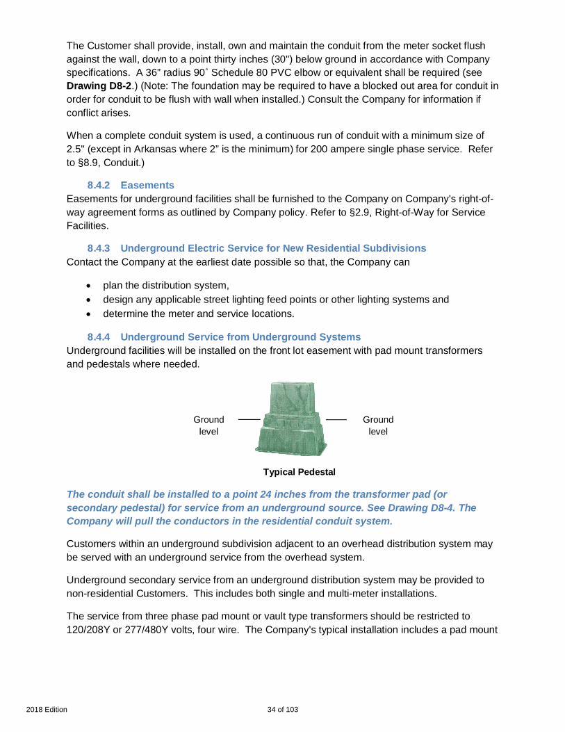
Underground Service from Underground Systems8.4.4Underground facilities will be installed on the front lot easement with pad mount transformersand pedestals where needed.
Typical Pedestal
The conduit shall be installed to a point 24 inches from the transformer pad (orsecondary pedestal) for service from an underground source. See Drawing D8-4. TheCompany will pull the conductors in the residential conduit system.
Customers within an underground subdivision adjacent to an overhead distribution system maybe served with an underground service from the overhead system.
Underground secondary service from an underground distribution system may be provided tonon-residential Customers. This includes both single and multi-meter installations.
The service from three phase pad mount or vault type transformers should be restricted to120/208Y or 277/480Y volts, four wire. The Company's typical installation includes a pad mount
Groundlevel
Groundlevel
34 of 1032018 Edition

transformer and/ or pedestals. Occasionally, other type transformers may be required. Consultthe Company for details.
Underground Service from Overhead Distribution System / Power Poles8.4.5The Customer shall install the end of the elbow coming up at a point 7 inches from the base ofthe pole for service from an overhead source.
The Company will install the Customer supplied riser on the pole. For Residential Service,Company will pull the conductors in the conduit system see Drawing D8-5. All others shouldconsult the Company.
Normally, conduits on a Company owned pole will be limited to one. More than one conduitmay be allowed in certain circumstances, with prior Company approval. Customers requestingadditional conduits may be required to provide a separate support structure for the conduits anda suitable attachment point for the Company owned overhead service conductors. When morethan one conduit is allowed, they shall be installed adjacent to each other, and not cover morethan one quarter of the pole circumference. At Company’s option an above ground pedestalmay be installed at Customer’s cost to accommodate additional service.
Underground Service Replacing Existing Overhead Service8.4.6An existing Customer served with an overhead service may request the removal of theoverhead service and the installation of a new underground service.
If the existing service is of adequate size to serve the load, the Customer is responsible forpaying the total estimated cost.
Where the existing service is not adequate to serve the increased load, the Customer shall paythe difference between the estimated cost of an underground service and a new overheadservice. Consult the Company.
Junction Box Requirements8.5A junction box is equipment designated/approved by the Company where the Customer'sservice terminals are joined to the Company's cables.
Junction boxes are not normally required or accepted for 120/208/240volt self-contained singlemeter installations or residential unless a main disconnect is required ahead of the meter.
When the Customer provides, owns, installs & maintains the secondary wire to the Company’stransformer, a Junction box is not required. Consult the Company for requirements in your area.
A Customer Supplied Company approved Junction box is required when Company ownedUnderground conductors feed the Underground Service and:
· A main disconnect is required (e.g. 480 volts service, etc.);· multiple services are joined together; or· transformer rated services exist.
For situations that can’t meet the standard junction box installation requirements consult theCompany.
35 of 1032018 Edition
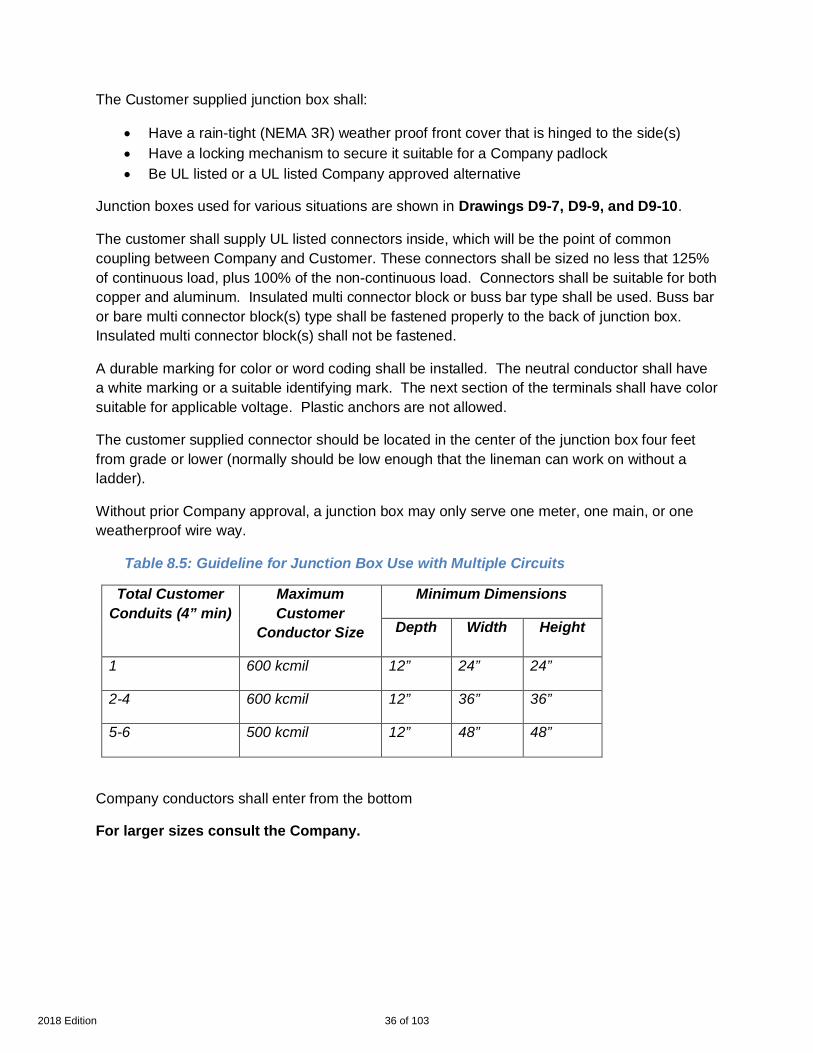
The Customer supplied junction box shall:
· Have a rain-tight (NEMA 3R) weather proof front cover that is hinged to the side(s)· Have a locking mechanism to secure it suitable for a Company padlock· Be UL listed or a UL listed Company approved alternative
Junction boxes used for various situations are shown in Drawings D9-7, D9-9, and D9-10.
The customer shall supply UL listed connectors inside, which will be the point of commoncoupling between Company and Customer. These connectors shall be sized no less that 125%of continuous load, plus 100% of the non-continuous load. Connectors shall be suitable for bothcopper and aluminum. Insulated multi connector block or buss bar type shall be used. Buss baror bare multi connector block(s) type shall be fastened properly to the back of junction box.Insulated multi connector block(s) shall not be fastened.
A durable marking for color or word coding shall be installed. The neutral conductor shall havea white marking or a suitable identifying mark. The next section of the terminals shall have colorsuitable for applicable voltage. Plastic anchors are not allowed.
The customer supplied connector should be located in the center of the junction box four feetfrom grade or lower (normally should be low enough that the lineman can work on without aladder).
Without prior Company approval, a junction box may only serve one meter, one main, or oneweatherproof wire way.
Table 8.5: Guideline for Junction Box Use with Multiple Circuits
Total CustomerConduits (4” min)
MaximumCustomer
Conductor Size
Minimum Dimensions
Depth Width Height
1 600 kcmil 12” 24” 24”
2-4 600 kcmil 12” 36” 36”
5-6 500 kcmil 12” 48” 48”
Company conductors shall enter from the bottom
For larger sizes consult the Company.
36 of 1032018 Edition
Underground Service from an Underground Network8.6Specific portions of the distribution system in downtown areas with highly concentrated loadshave been designated as Underground Network Areas. Area boundaries may be obtained fromthe Company.
Service for individual loads up to 300 kVA may be provided directly from the secondary system.Voltages available are single phase, two or three wire, and three phase, four wire, and 120/208volts. In some networks, 277/480volts service may be available.
In Mississippi and Arkansas 125/216 volts service may be available. Consult the Company foravailable voltage at specific locations. Larger loads may require installation of one or moretransformers, which shall be located in a suitable vault furnished by the Customer. TheCompany and authorities having jurisdiction shall approve the vault and its location. Contact theCompany to arrange for such an installation or to arrange for service at other voltages.
The location of the point of termination of the service run shall be approved by the authoritieshaving jurisdiction and by the Company. Consult the Company for service requirements.
Underground Electric Service for Mobile Homes8.7See §4.6 Services for Individually Located Mobile Homes and Travel Trailers.
Underground Electric Service for Mobile Home Parks8.8See §4.7 Services for Mobile Home Parks.
Conduit8.9
General Comments8.9.1Conduit is the preferred system for primary, secondary and service cables.
Conduit is always required in places with
· restricted access, i.e. under or potentially undero concrete driveways,o sidewalks,o patios,o flowerbeds, etc.)
· poor local soil,· underground congestion of
o pipes,o other utilities service lines, or
· other conditions.
Consult the Company for details. Note: Louisiana service areas (which includes legacy ELL,legacy EGSL and ENO) requires customer’s provide and install conduit for the installation ofservice cables.
The Customer's anticipated future load requirements should also be considered when sizingcable and conduit to serve the Customer's present load requirements.
37 of 1032018 Edition

Poor Soil Conditions8.9.2Due to the quality of the soil in some portions of the Company’s service area, concrete aroundthe conduit may be required. If concrete encased conduit bends are required at the base of thepole or the entrance to the building service, the concrete shall be formed to prevent its touchingthe pole or building and a fibrous separator is required between the pole and the concrete.
Pull boxes /Pedestals (many bends, long cable)8.9.3Customer shall consult the Company if:
· There are more than three bends (any angle) including riser bends or· The cable run is greater than 200 ft. (Long cable runs may also require bigger cable and
conduit to compensate for voltage drops)
Customer shall provide a Company approved pull box (If vehicular traffic is expected on it, avault will be required). Customer shall install pull box in a Company approved location. Also seeDrawing D8-2. for secondary pull boxes/ pedestals. See Drawing D8-6 for a typical primaryservice to a single pad mount transformer serving commercial or industrial Customers.
Conduit Used in Commercial, Industrial, and Other Non-Residential8.9.4Underground Installations
Based upon Customer information and requirements, The Company shall specify:
· The number, design and location of pull boxes;· Total number of conduit runs including spare conduit runs;· Total length of conduit runs to be installed;· If pull boxes or junction boxes are required
Types of Conduit8.9.5
General Comments8.9.5.1Conduits above the ground and transition elbow or conduit from underground to abovegroundshall be electrical gray schedule 80 PVC or equivalent.
Nonmetallic conduit installed totally below grade shall be at least Schedule 40 PVC orequivalent and shall be electrical gray or black with red stripes for continuous conduit.
In certain cases, concrete encasement may be required according to Drawing D8-3 & D8-7. Allconduits, elbows, fittings, etc. shall be UL approved with an U. L. label, meet CompanySpecifications and Local Building Codes.
Elbows and bends8.9.5.2All Elbows and bends shall have a minimum 36” radius. Consult Company to learn if Companyapproved rigid galvanized steel elbows with 4” red concrete is required for primary cable.
38 of 1032018 Edition

Minimum Conduit* Guide for Typical Underground Conductor8.9.5.3
Secondary Conductors
Size Conduit
#4 Al Triplex 2.5” (2” in Arkansas only)
1/0 Al Triplex 2.5” (2” in Arkansas only)
4/0 Al Triplex 2.5” (2” in Arkansas only)
350 Al Triplex 3”
500 Al Triplex 3”
750 Al Triplex 5”
1000 Al Triplex 5”
1/0 Al Quadruplex 3”
4/0 Al Quadruplex 3”
350 Al Quadruplex 3”
500 Al Quadruplex 4”
750 Al Quadruplex 5”
1000 Al Quadruplex 5”
*The recommended conduit size conforms to the Company standards for conduit used on theCompany system. Consult the Company during the design process to ensure that the proposedconduit system meets Company requirements.
Termination of Customers’ Conductors in Company’s Transformers8.10When the Customer brings cable to the transformer see §1.5 labels.
The Company shall furnish terminals for secondary conductors when Company’s standardconnectors can be used.
The maximum size Company supplied connectors in:
· A single-phase transformer is for 500 kcmil cable,· A three-phase transformer is for 1000 kcmil cable.
39 of 1032018 Edition

Larger cable or cable with more strands than Company cable listed above (such as locomotivecable or welding cable), shall require Company approval of Customer furnished cable andconnectors. Customer may supply Aluminum or Copper cable designed for the application.Consult the Company in advance.
The Company will normally bolt all terminals to the connectors of the transformer. The phasingand proper conductor length will be the responsibility of the Customer regardless of who installsthe terminals or bolts the terminals to the transformer connectors.
For three phase loads where parallel service entrance conductors are installed, the Customershall consult with the Company early in the design phase to determine the number andsize of conductors that may be brought out for their system.
1. Pad mount transformers (Sized based upon Company guidelines and requirements notthe NEC)
· 500 kVA or smaller can accept eight conductors per phase;· 750 kVA and larger can accept twelve conductors per phase.
2. For underground service, buss duct or a Customer furnished, Company approvedjunction box should be required for loads that exceed the number of conductors theCompany can accept.
Metering for Underground Service8.11The meter installation shall be located outside of a building or structure. Refer to §9.4, Locationof Meter Installations. Disconnect switches or a main breaker panel shall be mounted within 2feet of the meter socket. Prior approval shall be obtained from the Company for the installationof any service equipment directly below the meter sockets.
Special metering options may be available with approval of the Company. The Customer shallbear the additional cost made necessary by the special metering options.
Transformers Used in Underground Installations8.12
General Comments8.12.1The Company will generally own and operate all transformers on the Company side of the pointof delivery. Pad mount transformers shall be installed in accordance with Companyspecifications. Vaults, enclosures, etc. (when used) will be at Customer's expense and shallconform to Company specifications. See Section 10 Transformers Vaults and Substations.
Transformer Pads or Slabs8.12.2The Company will generally furnish single-phase transformer pads. Three phase transformerpads / slabs shall be provided by the Customer, and shall conform to Company specifications.When supporting foundations are needed for the transformer installation the Customer will beresponsible for the design of the supporting foundation and for obtaining approval of the designby the Company.
40 of 1032018 Edition

Metering Installations and EquipmentSection 9General Comments9.1
Responsible Parties9.1.1The metering equipment is usually installed on the Customer's premises (on Customer ownedbuilding; pole or structure). The Company will provide, as required, meters, meteringtransformers, relays, color-coded cable and transformer-rated meter sockets. The type ofequipment supplied will depend on the requirements of the applicable rate schedule and theCompany's standard practices.
The Customer will be required to provide the Company with information regarding the totalconnected load. The Customer may be required to provide, maintain and / or install the metersocket, metering transformer enclosure and adequate attachments or devices for attachingCompany's metering facilities to the building. (This may require running conduit through eavesof roof and other similar necessities that could alter the Customer's building.)
Meter Socket Specifications9.1.2
General9.1.2.11. All meter sockets have a UL label which signifies they meet ANSI C12.7 and UL 414. In
accordance with all applicable codes, a socket shall be properly installed and used inthe application for which it is designed. All outside meter sockets shall be weatherproof/rain-tight (NEMA 3R).
2. The metering installation should be as tamper-proof as possible. The equipment shallbe good quality and strength so that corrosion and deterioration will not present safetyproblems and require the Customer to replace the meter socket. The Company at itsoption can require the Customer to replace obsolete metering facilities that cannotaccept Company meters.
3. All meter sockets shall be sealable and in serviceable condition. Customer shallproperly seal all unused openings on the meter socket assembly. The Companyrecommends meter socket that provide a knockout in the front cover and flange insidefor barrel-locking.
4. Meter socket shall be large enough to accommodate conductor size.5. Overhead sockets are required in overhead installations and underground sockets are
required in underground installations.6. No Customer device shall be allowed between meter and socket.7. Load and line wires shall not cross in the meter socket.8. If ring-type sockets are used, Customer shall supply a meter ring to secure the meter in
the socket. The ring should be stainless steel.9. Meter sockets shall not be used as junction boxes.10. All meter sockets - except residential single phase less than 320 Amps - shall have a
manual mechanical gang operated bypass switch. Horn bypasses and similar devicsesare not allowed. (Any commercial 100 amp service such as billboards and other non-critical small commercial services should consult with the Company.)
41 of 1032018 Edition

11. Service entrance wires shall enter and stay opposite of the bypass switch.12. For 5 terminal meter sockets, the 5th terminal shall be supplied by the Customer and
physically secured to the meter socket. It should be re-locatable but shall be securelyattached to the socket in the proposed operating position.
13. The lugs in 320 Amp meter sockets shall accept up to 500 kcmil conductors.14. All Underground Connected meter sockets & power panels shall be side-wired.15. Power panels /combination meter/ breaker boxes --- The wires behind the breakers
and the Company wires shall be behind separate barriers. Company personnel shallhave access to Company wires without exposing the wires behind the breakers.
Meter Transformer Enclosure Specifications9.1.3The Company specifies instrument transformer enclosures that accommodate the Company’sequipment standards. Customers should determine the enclosure size based upon the size and numberof service conductors. Instrument transformers shall be bolted to the back-plate and each shall becapable of being removed individually.
All enclosures shall:
· Have a metal or ¾” treated plywood back-plate in addition to the back wall of theenclosure
· Be UL listed· Be weather proof/rain-tight(NEMA 3R)· Have a locking mechanism to secure it suitable for a Company padlock
(handles with keys not acceptable)· Be side-hinged· Be minimum Aluminum or 14 gauge G90 steel enclosure
Table 9.1.3: Guideline for Meter Transformer Enclosure with Multiple Circuits
Total CustomerConduits (4” min)
MaximumCustomer
Conductor Size
Minimum Dimensions
Depth Width Height
Up to 4 600 kcmil 14” 32” 40”
Up to 6 500 kcmil 14” 32” 54”
CTs will be placed at center. Customer Conduit spaced evenly.
Service connections shall not be made in an instrument transformer enclosure.
For larger sizes consult the Company.
42 of 1032018 Edition

Meter Connections and Seals9.2The Company shall install the meters, seal all meters, and seal all instrument transformerenclosures. Except as noted below, only the Company and its authorized agents are permittedto break or replace a seal, or to remove or change a meter. A licensed electrical contractor shallobtain approval prior to removing any meter seal, or notify the Company after doing so underemergency circumstances. Any infringement or violation shall be dealt with in accordance withthe Company procedure for dealing with meter tampering.
Meter Clearance9.3Meters and metering equipment enclosures shall be mounted in locations that will provide atleast 15 inches clearance on all sides and at least three feet in front. Equipment and clearancesshall be within Customer’s property. Some additional requirements for distance between a gasmeter and an electric meter are as follows:
· National Gas Code - Gas Meter Locations: Gas meters shall be located at least 3 feet(0.9m) from sources of ignition.
· Office of Pipeline Safety - Minimum Federal Safety Standard: Customer meters andregulators …each meter installed within a building must be located in a ventilated spaceand not less than 3 feet (0.9m) from any source of ignition or any source of heat thatmay damage the meter.
An electric meter is a possible source of ignition.
Location of Meter Installations9.4An outdoor meter installation is the Company’s standard.
For residential service, the meter is to be located on the outside of the building on the side ofresidences within 3 feet of the front wall and outside of fences on the side most economical toreach the Company’s facilities. This location minimizes the Company's required access to theCustomer's premises.
Prior written approval of the Company is required to locate the meter other than in the preferredlocation, and the Customer shall pay any and all appropriate charges.
Locations inside porches or beneath carports are not considered as being outdoors and may notalways be accessible by Company personnel.
The meter shall be in a safe location accessible to the Company at all hours. If the meteringinstallation is difficult to access, the Company may require the use of the Customer's telephoneline to access the meter for reading and programming.
The meter shall not be installed above or behind any piece of apparatus or machinery. Thelocation should minimize the possibility of damage from moisture, vibration, dirt, mechanicaldamage and corrosive or dangerous fumes. Any code and / or safety violation may requirerelocation of the meter at the Customer’s expense.
43 of 1032018 Edition
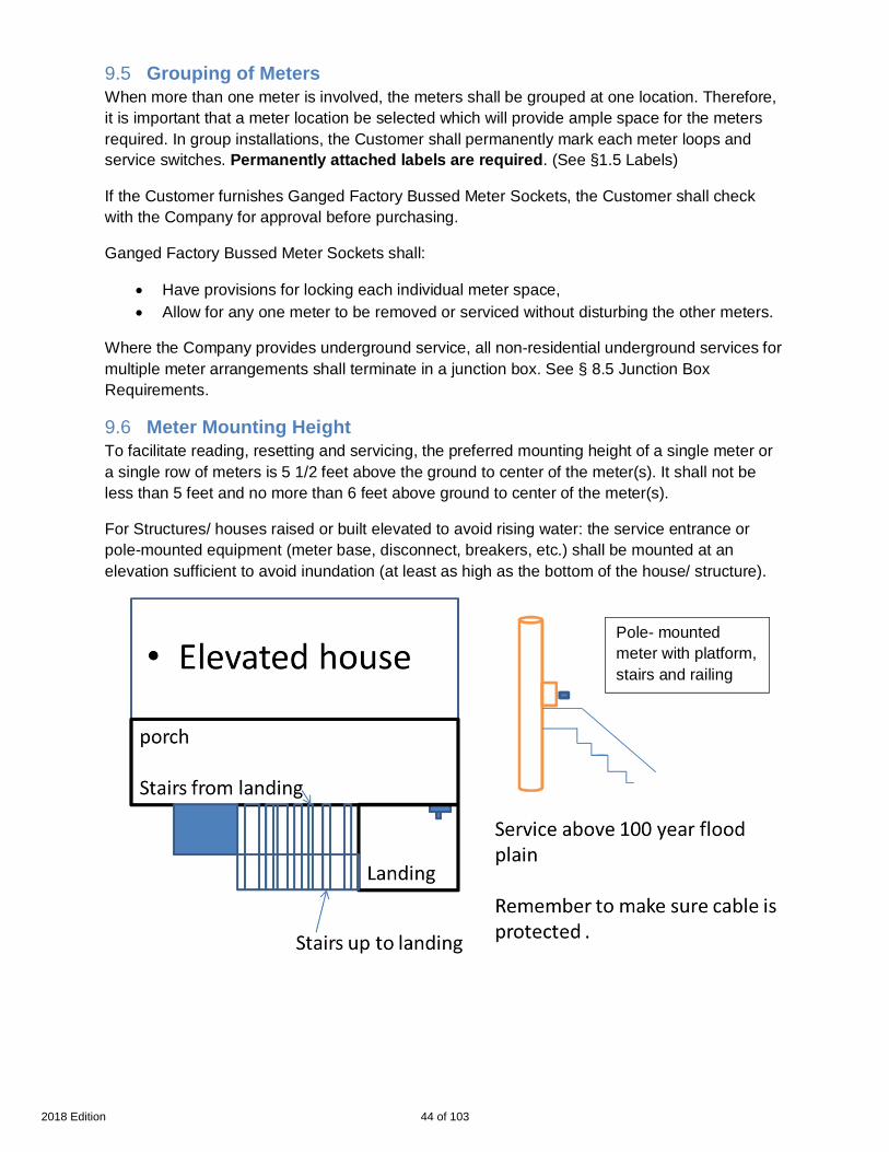
Grouping of Meters9.5When more than one meter is involved, the meters shall be grouped at one location. Therefore,it is important that a meter location be selected which will provide ample space for the metersrequired. In group installations, the Customer shall permanently mark each meter loops andservice switches. Permanently attached labels are required. (See §1.5 Labels)
If the Customer furnishes Ganged Factory Bussed Meter Sockets, the Customer shall checkwith the Company for approval before purchasing.
Ganged Factory Bussed Meter Sockets shall:
· Have provisions for locking each individual meter space,· Allow for any one meter to be removed or serviced without disturbing the other meters.
Where the Company provides underground service, all non-residential underground services formultiple meter arrangements shall terminate in a junction box. See § 8.5 Junction BoxRequirements.
Meter Mounting Height9.6To facilitate reading, resetting and servicing, the preferred mounting height of a single meter ora single row of meters is 5 1/2 feet above the ground to center of the meter(s). It shall not beless than 5 feet and no more than 6 feet above ground to center of the meter(s).
For Structures/ houses raised or built elevated to avoid rising water: the service entrance orpole-mounted equipment (meter base, disconnect, breakers, etc.) shall be mounted at anelevation sufficient to avoid inundation (at least as high as the bottom of the house/ structure).
Pole- mountedmeter with platform,stairs and railing
44 of 1032018 Edition

If the height of the meter is increased, Customer shall furnish a permanent 4 feet by 4 feet (4’ X4’) platform, five to six feet below the center of the meter with permanent rails around theplatform and steps. Consult Company for details (also see Drawings D9-13 & D9-14).
Where two meters are mounted vertically on a wall as a gang installation, the upper meter shallbe mounted at least 5 1/2 feet to center above ground, and not more than 6 feet to center aboveground. The lower meter shall be mounted so as to allow three inches clearance between metersockets. Where more than two meters are to be installed as a gang installation, they shall bemounted in horizontal rows.
Individually metered apartment complexes may have meters installed in manufacturedcombination meter enclosure and switchgear assemblies. Such assemblies shall not have morethan six horizontal rows of meters.
Assemblies installed indoors or in enclosures, the center of the highest meter shall not be morethan 6 1/2 feet above the floor and the center of the lowest meter shall not be less than 18inches above the floor or bottom of enclosure
Assemblies mounted on the exterior walls of a building or on poles, the center of the highestmeter shall not be more than 6 1/2 feet above finished grade and the center of the lowest metershall not be less than 34 inches above finished grade. Assemblies mounted on the outside shallbe rain tight.
The Company, at its option, may require a barricade to be installed to prevent damage to themeters or encroachment on the clearances (driveways, parking lots, etc.)
Types of Meter Installations9.7
Self-Contained Metering Installations9.7.1Normally, residential and small non-residential loads are metered with self-contained meters.
Customers desiring three-phase service with loads above 200 amps should consult theCompany concerning availability of self-contained meters. All three phase self-contained metersshall have a meter socket containing a by-pass switch. All three-phase, four wire, 120/ 240 voltsself-contained meter installations shall have the high voltage leg clearly and properly identifiedat the service entrance and connected to the right-hand (line) side of the meter socket.
Instrument Transformer Installation9.7.2When in the Company’s judgment the load exceeds the capacity of a self-contained meter (320Amps), the Company shall provide instrument transformers and a transformer-rated socket. TheCompany will determine the type of metering to be used. When in the Company’s judgment theload does not exceed the capacity of a self-contained meter, the customer shall be responsiblefor the cost of any additional metering equipment.
Unless specified by the Company, an instrument transformer enclosure is required for alltransformer-rated installations (see 9.1.3 Meter Transformer Enclosure Specifications). Thebottom of the enclosure shall not be less than twelve inches above final grade. The center of
45 of 1032018 Edition
the enclosure shall not be more than six feet above grade. All transformer-rated sockets shouldbe no more than 25 feet from the instrument transformer enclosure.
The Customer or contractor contemplating an installation of this nature shall consult with theCompany as to the number, size, location of and provisions for mounting instrumenttransformers and metering enclosures. Upon request, the Company will furnish informationregarding the type, dimensions and connections of metering equipment to be used. For largerinstallations it is essential that such information be obtained before wiring plans are completed.
All three phase, four wire 120V/240 volts transformer-rated installations shall have the highvoltage leg clearly and properly identified at the service entrance. If the transformers aremounted horizontally, the high voltage leg should pass through the right-most transformer. Ifmounted vertically, the high voltage leg should pass through the bottom transformer.
Primary Metering Installations9.7.3Consult the Company in Advance. The three options for furnishing service involving primaryvoltage delivery or metering are as follows:
1. For specific information on voltage transformation, consult the company.2. Primary voltage delivery and metering: All service is delivered and metered at primary
line voltage and the Customer owns and maintains all of the service transformers andsubstation installation, except for the metering equipment.
3. Primary voltage metering and secondary voltage delivery: All service is metered atprimary line voltage and the Company owns some or all of the service transformers orsubstation installation. The Customer takes delivery at the secondary voltage level.
4. Primary voltage delivery and secondary voltage metering: All service is delivered atprimary line voltage and the Customer owns and maintains all of the service installationon the Customer's premises, except for the metering installation. The meters are part ofthe service installation on the Customer's premises, but they are owned and maintainedby the Company. Service is metered at the secondary voltage level.
Regardless of the option desired, when the metering installation is located on the Customer'spremises, the Customer shall provide a suitable location without cost to the Company. TheCustomer shall also provide the Company suitable right-of-way over the premises for theCompany's overhead primary circuit to the substation or in lieu thereof an underground servicefor primary voltage may be provided.
Meter Grounding9.7.4Grounding the metering installation is a safety consideration both for the Company and theCustomer. The grounding connection shall be made in accordance with code and preferably inthe meter socket. If the grounding connection is made anywhere other than the meter socket,the Customer shall be responsible for grounding continuity between the point where thegrounding is made and the meter socket.
Service Disconnecting Means9.7.5All equipment must be U. L. approved and be installed in enclosures suitable for prevailingconditions, such as weather extremes or corrosive environments.
46 of 1032018 Edition

Disconnecting Means for Services Less Than 600 Volts9.8
Self-contained meters (240 volts nominal, 320 amps maximum per service)9.8.1The Customer is required to provide a means of disconnecting all energized wires from thesource of supply. The disconnecting means may consist of not more than six switches with overcurrent protection or six manually operable circuit breakers mounted in a single enclosure.
In a group of separate enclosures, or in a switchboard, the disconnecting means shall belocated in a readily accessible location near the point of delivery, within 10 feet, preferably onthe outside of a building or structure or on the inside wall directly behind the outside serviceentrance. For residences, the main breaker should be a maximum of 2 feet horizontal andvertical from the meter.
480 volts service, self-contained meters9.8.2See §7.7 480 Volts Metered Service
Instrument Transformer Installation9.8.3See Disconnect or Disconnect switch §1.5.
The Customer shall provide a means of disconnecting all energized conductors of each serviceentrance from the source of supply. The disconnecting means shall comply with code and/orauthorities having jurisdiction.
Where the Customer has self-generation or takes two or more points of service that can be tiedtogether, automatic trip circuit breakers shall be required. Relaying on these circuit breakersshould be coordinated with the Company.
For disconnecting means required on service above 4160/2400Y volts, contact the Company.
Isolation Switches for Services Over 600 Volts9.8.4The Customer shall install isolating switches between the supply conductors and thedisconnecting means. This disconnecting means shall separate the conductors of the circuitfrom any source of supply.
Isolation switches are not required where disconnecting equipment is mounted on removablepanels or metal-enclosed switch gear units which cannot be opened unless the circuit isdisconnected, and which, when removed from the normal operating position, automaticallydisconnects the circuit breaker or switch from all live parts.
Fuses or cutouts used with non-automatic oil switches as disconnecting means may serve asisolating switches provided that they can be operated as a disconnect switch and completelydisconnect the oil switch and all service equipment from the source of supply. The Customershall be equipped to operate the fuses or cutouts.
Pole top air break switches accessible to the Customer’s authorized personnel only andarranged so that grounding connection can readily be made on the load side may be used asisolating switches.
47 of 1032018 Edition
Alternate Sources and Automatic Transfer Systems9.8.5If the Customer desires to have an additional distribution feeder as the second source, theCustomer is responsible for the costs to install, operate and maintain the Company’s additionalfacilities, as well as cost for reserve capacity in addition to the charges, if any, required for theoriginal service.
An automatic transfer switch may be specified as part of any alternative source system. TheCompany does not normally specify switches that are installed on the Customer’s premises,past the metering point. However, any automatic switch connected to the Company’s systemshall be able to sense a dead power line and shall be blocked from closing in on the dead line.The Customer shall be responsible for the consequences of any back feed that occurs due tothe switch closing in on a dead power line.
The automatic transfer system shall block any faults occurring in the Customer’s facilities fromthe utility system.
Furthermore, a closed transition transfer switching (CTTS) (make-before-break) application,while momentarily paralleling the Customer’s system to the original power source, shall limit theparallel power feed to 10 cycles or less after a fault occurs. This CTTS (make-before-break)application shall be performed while the utility supply is energized and shall contain thenecessary synchronizing checks.
Consult the Company for automatic transfer system guidelines.
48 of 1032018 Edition

Transformers, Vaults and SubstationsSection 10General Comments10.1
When large concentrated loads or long distances are encountered, it may be necessary toinstall transformers and high voltage conductors on or in the Customer's property. Whentransformers are to be installed outside, on, or in the Customer's property, the Customer shallprovide a suitable location. The Customer shall consult the Company regarding thelocation, size, and construction of the facilities during the design and planning phase.
The Company will not energize its facilities until the installation is:
1. Made in accordance with manufacturer recommendations and engineering standards,2. Approved by authorities having jurisdiction and,3. Acceptable to the Company.
Access, Fences, Screen Walls, Decorative Walls10.2Adequate access and support to accommodate line trucks or other necessary lifting and haulingequipment shall be provided and maintained by Customer to allow for maintenance, operationor replacement of equipment at all hours without notice.
The Customer shall equip each door (or other barrier) between the transformer and the nearestpublic access with Company provided locks or Company approved alternate.
The Company will not construct, reimburse the Customer, or accept ownership andmaintenance responsibility of any fences, screen walls, or decorative walls which restrict accessto Company facilities. Prior written approval shall be obtained from the Company before theCustomer constructs such walls or fences. See Drawing D10-1.
The Company will construct or reimburse the Customer and accept ownership and maintenanceresponsibilities for chain link fences meeting Company specifications which are required forprotection around ground type substations.
Types of Transformer Installations10.3The Company provides electric service from one of the following general transformerinstallations:
1. Pole mounted transformers, one or cluster of two or three transformers,2. Two pole transformer platforms,3. Ground substations-fenced,4. Padmount transformers,5. Transformer vaults-usually on the Customer's premises.
49 of 1032018 Edition

Pad Mount Transformers10.4Pad mount transformers are generally provided, owned and maintained by the Company forunderground service. Consult the Company for requirements and availability in totallyunderground systems.
For ready access to unenclosed pad mount transformers, a minimum clearance of three feetfrom the side and back edges of the pad and twelve feet from the front of the transformer shallbe maintained at all times. See Drawing D10-1 for other restrictions on transformer placement.The Company, at its option, may require a barricade to be installed to prevent damage to themeters or encroachment on the clearances (driveways, parking lots, etc.)
For pad-mount transformers in non-residential applications, the Customer may be required toprovide the conductors to the transformer secondary terminals.
Transformer Vaults10.5Transformer vaults are generally provided, owned, and maintained by the Customer on theCustomer's premises and constructed in accordance with the Company's specifications and allapplicable codes. Vaults should be located where they can be vented to the outside air withoutducts.
In above ground vaults, venting shall be provided by louvers in the doors or combination of doorlouvers and wall louvers. Consult company for the total square footage of louver required. Forexample “free area of louver space” shall be equivalent to 5.17 sq ft (0.48 sq m) = 32.3% for 48"x 48". Acceptable louvers shall be site proof, tamper resistant, and meet all of the localstructural building codes.
Vaults shall be provided with suitable hasps for the Company's padlock. These locks will beprovided by the Company and installed by the Customer.
The Company will generally provide and install the transformers and primary cables in theCustomer's vault. The Customer will provide the transformer vault, service conduits, and extendthe service cables into the vault. The cable extensions shall have sufficient length of slack cablefor the Company to connect them to its facilities. If the customer utilizes a buss terminationinstead of cables, the buss shall meet the requirements shown in Drawing 10-2. Thecustomer’s switchboard/switchgear shall have lockable, separated compartment to houseCompany’s current transformers (CT)s and an area inside the compartment to house thepotential transformers (PT)s. The meter shall always be located outside the transformer vault.
Termination of Secondary Conductors to Transformers for Non-10.6Residential Services
Terminals for secondary conductors shall be installed as provided in § 8.10, Termination ofCustomer’s Conductors in Company’s Pad-Mounted Transformers.
The phasing, sizing and proper length of conductors is the sole responsibility of the Customer.The Customer shall also be responsible for properly marking the phases. The Company willgenerally make connection of the terminals to the connectors of the transformer.
50 of 1032018 Edition

Customer’s Motors & CapacitorsSection 11General Comments11.1
The Company recommends that the Customer's wiring be designed so that the voltage dropbetween the disconnecting means or service entrance switch, and the farthest outlet is limited tonot more than 2% at full load. Consult the Power Quality Standard for Electric Service §16 forthe voltage sag on the primary side of a distribution transformer.
Motor - Voltage Rating11.2Single-phase motors manufactured under American National Standard Institute (ANSI)Standard C84.1 have 115 or 230 Volt nameplates and, if three phase, have 208, 230, 460,2,300, 4,000, or 13,200 Volt nameplates. These are nominal voltage ratings and do not implythat the motors shall be operated at the exact voltages supplied. Motors may be supplied withnominal voltages as listed below:
Nominal Voltage Rating of Motors
Type ofService
Motor Voltage Rating -Nameplate
Nominal SupplyVoltage
Single Phase 115 120
Single Phase 230 240
Three Phase 208 208
Three Phase 230 240
Three Phase 460 480
Three Phase 2,300 2,400
Three Phase 4,000 4160
Three Phase 13,200 13,800
All motors should have a manufacturer's nameplate indicating the voltage, current rating, speedand horsepower rating for continuous or intermittent use as the case may be. This nameplateshould also carry the NEMA "code letter" designation of the motor. When a motor is rewound toproduce a change in its original design, a new nameplate should be attached indicating the newcharacteristics and the name of the firm or person making the change.
51 of 1032018 Edition

Motor Starting11.3
General Comments11.3.1The Customer's equipment shall have good starting characteristics to protect Customer’sequipment and other Customers. The Company finds it necessary to establish certain limitationsfor the maximum allowable starting currents of motors to be connected to its lines.
Frequency of starting is also a factor. Considerable latitude in the amount of starting current ispermissible under certain conditions, especially where the motors are started not more than twoor three times per day.
Consult with the Company on the acceptability of the proposed installation.
Single Phase Motors11.3.2
Horsepower Rated11.3.2.1Single-phase motors rated in horsepower may be started "across the line”, that is, at full ratedvoltage by merely closing a switch. It is recommended that single phase motors larger than 1/2hp be operated at 240 or 208 volts. Locked rotor current specified in the Table below will bepermitted under the following conditions only:
· When such motors are provided with proper current limiting starting equipment; or· When the total locked rotor currents of two or more smaller motors, which may be
started simultaneously, are less than the allowable locked rotor current of the largestmotor in said installation.
Allowable Starting Currents for Single Phase Motors
Equipment Rated Maximum Allowable Locked RotorCurrent
115 volts
All Sizes 50 amps
230 volts
2 hp. or less 60 amps
3 hp. 80 amps
5 hp. 120 amps
6-1/2 hp. 150 amps
Over 6 1/2 hp. Consult the Company
52 of 1032018 Edition

Air Conditioners and Heat Pumps --Btu/h Rated11.3.2.2Air Conditioners up to 60,000 Btu/h (5 ton) rating will be served single phase provided they donot exceed the locked rotor current values below.
Single Phase Air Conditioning and Heat Pump Equipment Rated In BTU per Hour
Equipment Rated Maximum Allowable Locked Rotor Current
115 volts
All sizes 50 amps
230 volts
20,000 BTU/H or less 60 amps
20,000 Btu/h to and including60,000 Btu/h
60 amps plus 3 amps per 1,000 Btu/h in excess of20,000 Btu/h (150 amps max)
Over 60,000 Btu/h Consult the Company
Three Phase Motors11.3.3
Horsepower Rated11.3.3.1Consult the Company for motors of 10 hp size and larger to determine the maximum value ofstarting current permissible at a given location. Refer to §11.6, Converters - Operation of ThreePhase Motors from Single Phase Electric Supply, for phase converter operations.
Btu/h Rated11.3.3.2Where it has been determined that three-phase service will be rendered, motor starting currentsshall not exceed the following values:
· 159 amps if the service voltage is 208 V,· 150 amps if the service voltage is 230 V or,· 75 amps if the service voltage is 460 V.
For motors exceeding these values and for units greater than 120,000 Btu/h, (10 tons), it will benecessary to provide facilities to limit the starting current to values specified by the Company forthe location involved.
Motor Starting and Control Equipment11.3.4All motors and motor control equipment shall be installed in accordance with the Power QualityStandard for Electric Service, §16 and any other referenced code.
Auxiliary starting devices shall be used on all motors that cannot be safely subjected to fullvoltage while starting. The auxiliary starting device should be designed in such a way that themotor can be thrown into the running position before the motor has reached rated runningspeed in the starting position. Typically, electric irrigation motors above 60 hp served at three
53 of 1032018 Edition

phase, 480 volts will be started with reduced voltage starting equipment. The Company mayspecify the particular voltage tap setting to be used.
Motor Starters/Controllers can create harmonic disturbances that have detrimental effects onthe Company's electric system and/or service to other Customers. Disturbances of this natureshall be corrected at the Customer's expense. Consult the Company.
Critical Service Motor Operation11.4Where continuous operation of a motor is essential, the no-voltage release should have a timedelay relay, which will prevent the opening of the circuit in the event of momentary voltagefluctuation. The Company will assist the Customer in selection of an automatic starting deviceand any other device to hold motors on line during voltage disturbances.
Motor Protection11.5
Phase Reversal Protection11.5.1Reverse phase relays are required on three phase elevator services by the NEC. Customershould install them where accidental reversal of motor rotation would cause seriousinconvenience, damage, or delay. The Company shall not be responsible for any damagescaused by phase reversal.
Over Current Protection11.5.2Motor protection is the responsibility of the Customer. The NEC requires that adequate overcurrent protection be provided in each phase on all motor installations.
Partial or Complete Loss of One or More Phases11.5.3The Customer shall ensure complete protection against Partial or Complete Loss of One orMore Phases or "single-phasing" on all three-phase motors.
The Company operates the three-phase distribution system with single-phase devices Singlephasing on the distribution system is necessary at times for fault clearing and switching andoccurs occasionally due to unforeseen circumstances. The Company shall not be heldresponsible or liable for damage to the Customer's installation due to such causes in theinherent operation of their distribution system.
Converters - Operation of Three Phase Motors from Single Phase11.6Electric Supply
The phase converter is used to simulate a three-phase voltage from a single-phase source. Oneconverter is recommended for each three-phase motor. The phase converter shall be matchedwith both the motor horsepower and the motor application. Special consideration shall be givento the type of phase converter being used on the motor. The Company shall be consulted priorto the installation of a phase converter.
54 of 1032018 Edition

Customer’s Capacitors and Other Reactive Equipment11.7It is important to maintain the power factor of any load as near unity as possible. This maysuggest the installation of capacitors.
The Customer shall provide automatic disconnecting of capacitors when the equipment causingthe low power factor is not operating.
Where large capacity motors are to be installed, consideration should be given to the use ofsynchronous type equipment.
55 of 1032018 Edition
Customer’s Special EquipmentSection 12General Comments12.1
The Customer, early in the design phase, shall submit to the Company information andspecifications of any equipment that might cause interference with the service to the Customeror to other Customers. Customer shall also present proposed remedies. The Company will notconnect electric service until all problems that may cause interference with other Customers hasbeen remedied by the Customer. See §16 Power Quality.
The Company reserves the right to inspect and test any equipment connected to its lines and torequire that such equipment be provided with nameplates showing the voltage, phase, full-loadamperes, maximum current, maximum kVA and such other information as may be necessary todetermine the operating characteristics of the equipment.
The Company has the right to suspend service for interference with the use of service of others.
Customer’s Sensitive Equipment12.2Equipment such as computers and other sensitive electronic devices may be adversely affectedby minor voltage variations. It is the Customer's responsibility to provide any uninterruptiblepower supplies, voltage regulating equipment or other protective apparatus for these sensitivedevices and equipment.
Antennae & Dishes12.3Antennae and Dishes for radio, radio transmitter, television, etc. shall never be erected over,under, or in close proximity of either side of the Company's power lines or other wires carryingelectric current. Nor should they be constructed in such a place where they may accidentally fallinto energized wires. Wires shall not cross over, or under Company's electric conductors. Suchlocation of the Customer's apparatus may result in serious accidents, damage to the equipment,or poor reception. Where proximity to electric power service conductors cannot be avoided, aten-foot minimum clearance is required. The attachment of antenna/ dishes systems to poles orservice masts carrying the Company's conductors is strictly prohibited. The Company willremove such attachments upon discovery, and the responsible party will be billed for all removalcosts.
CATV and Carrier Installations12.4Service for the operation of transmitting apparatus will be furnished under conditions specifiedby the Company and conditions of use of such service shall not cause undue disturbance ofelectric service to other Customers.
Where necessary, the Customer shall install suitable filters or other devices to prevent radio,telephone, television, etc. interference by the electrical power supply.
Consult the Company for installation of community antenna television (CATV) systems onCompany poles. The Customer shall sign a Service Agreement and the Company will designatethe service locations and specifications for attachment and operation on Company poles.
56 of 1032018 Edition

Radio and Television Interference12.5Some equipment may cause unsatisfactory operation of television, radios and other electronicequipment. The Customer is responsible for designing and operating their equipment to FCCstandards and avoid causing interference and damage to utilities and others equipment. An U.L. approved interference suppresser can eliminate or minimize this interference. See §16.
Facilities for Highly Fluctuating or Special Loads12.6Highly fluctuating loads such as welders, X-ray machines, and motors with unusual or frequentstarting requirements may interfere with other Customers' electric service. See § 5.5
57 of 1032018 Edition

Arc FlashSection 13You may request Arc Flash information online at Entergy.com or call Entergy at 1-800-ENTERGY (1-800-368-3749)
58 of 1032018 Edition

Consumer Owned Generators (not connected to utility)Section 14General14.1
The Customer may have generators that are NEVER connected to the Entergy distributionsystem.
Electrical Emergency or Standby Systems not connected14.2An example is an emergency generator where electric cords are run directly to this generatorfrom refrigerator, free standing lights, appliances etc. Refer to your local inspectors in this caseand manufacturer’s operating guidelines.
Permanently Installed Generators (not connected to utility)14.3Example: A house/building has a switch, rated for the customer’s generator size that does notallow electricity to flow from the generator into the facility when the facility is connected to thegrid.
No Customer device shall be allowed between meter and socket. (See §9.1.2.1 #6)
Refer to your local inspectors in this case.
There is never a path from these generators to the Company’s distribution grid.
Temporary Connection of Emergency Generators14.4The Customer shall supply an open and visible break verifiable by Company personnel.. Thelocation shall be on the outside of the facility accessible to Company personnel at all hours. Amain disconnect in the off position qualifies as an open break.
Failure to have a visible break is reason for being disconnected, and subjects Customer toliability for resulting injury to people or property.
Customer Facility
Entergy Distribution Customer Owned Generator
Note: switch can choose oneor the other power source; not
59 of 1032018 Edition

Generators Interconnected to and Operating in ParallelSection 15with the Utility Grid
Examples include Fossil, Solar, Wind, Hydro, Geothermal, Biomass, Fuel Cell, Micro turbine, others
An Interconnection Agreement with the Company is required before the Customer connects anelectrical generator directly to the distribution system or to a building, house, etc. that isconnected to the distribution system for any length of time from a fraction of a second to hours,days, years.
The Customer shall consult the Company early in the design phase.
For complete information refer to the Company’s policies for Connecting Electric Generators tothe Entergy Distribution System available online at www.Entergy.com or calling Entergy at 1-800-ENTERGY (1-800-368-3749).
Generation facilities other than the Company’s shall be permitted to interconnect and operate inparallel with the Company’s distribution system provided that all of the following are metthroughout the life of the interconnection:
1. The safety of the general public and the personnel and equipment of the Company shallin no way be reduced or impaired as a result of the interconnection.
2. The quality, reliability, and the availability of service to the Company's other Customersshall not be diminished or impaired as a result of the interconnection.
3. The generator is connected through a lockable switch which has an open and visiblebreak verifiable by Company personnel. The Customer shall supply a disconnect methodacceptable to the Company. The location shall be on the outside of the facility accessibleto Company personnel at all hours. Customer, at his own expense, shall meet all safetyand performance standards established by local and national electrical codes includingthe National Electrical Code (NEC), the Institute of Electrical and Electronics Engineers(IEEE), the National Electrical Safety Code (NESC), and Underwriters Laboratories (UL)and any other relevant standards.
4. A written interconnection agreement between the Company and Customer coveringparallel operation of Customer generation and the proper coordination of protectivedevices has been executed and is in force. The Company may enter the Customer’spremises to inspect the Customer’s protective devices and read or test the meter. TheCompany may disconnect the interconnection facilities without notice if the Companyreasonably believes a hazardous condition exists and such immediate action isnecessary to protect persons, or the Company’s facilities, or property of others fromdamage or interference caused by the Customer’s facilities, or lack of properly operatingprotective devices.
60 of 1032018 Edition

Power Quality Parameters for Customer EquipmentSection 16Specifications
The best time to address power quality issues is during the design stage of a new facility orplant expansion. The Power Quality Standard for Electric Service was developed to aidCustomers in specifying new equipment and in determining the need for power conditioningequipment for critical systems. See § 1.3 for the Internet location. The Company’s and otherCustomers’ equipment shall not be adversely impacted by a new Customer’s facilities or anexisting Customer’s planned expansion.
The Company should be consulted early in the design phase for new installations andload additions to address specific installation requirements for new facilities andplanned expansions.
61 of 1032018 Edition

Drawings for 2018 Customer Installation StandardsSection 2 Drawings - Safety, Customer's Service Obligations and Protection
No. Description Page Number
D2-1 BRACING 65
Section 4 Drawings - Types of Service
No. Description PageNumber
D4-1 TEMPORARY POLE SERVICE FROM ANOVERHEAD SOURCE
66
D4-2 TEMPORARY POLE SERVICE FROM ANUNDERGROUND SOURCE
67
D4-3 SERVICE TO PERMANENT POLE LOCATIONFROM AN OVERHEAD SOURCE (EX. MOBILEHOMES)
68
D4-4 PERMANENT POLE OVERHEAD SERVICEDETAILS FOR SINGLE MOBILE HOME ORSTRUCTURE
69
D4-5 PERMANENT POLE - UNDERGROUND SERVICETO LOCATION (EXAMPLE MOBILE HOME)
70
D4-6 PERMANENT POLE - UNDERGROUND SERVICEDETAILS FOR SINGLE MOBILE HOME ORSTRUCTURE
71
D4-7 TYPICAL INSTALLATION - CENTRAL SERVICEPOLE (FARMS, AND MULTIPLE SERVICEDROPS.)
72
D4-8 MULTIPLE METER SERVICE FOR MOBILE HOME120/240 VOLT UNDERGROUND SERVICE.
73
D4-9 MULTIPLE METER SERVICE FOR MOBILE HOME120/240 VOLT OVERHEAD SERVICE
74
D4-10 TYPICAL LAYOUT FOR MOBILE HOME PARKWITH MULTIPLE METER INSTALLATIONS
75
62 of 1032018 Edition
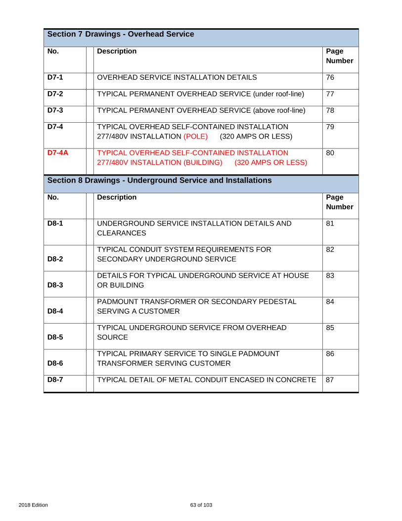
Section 7 Drawings - Overhead Service
No. Description PageNumber
D7-1 OVERHEAD SERVICE INSTALLATION DETAILS 76
D7-2 TYPICAL PERMANENT OVERHEAD SERVICE (under roof-line) 77
D7-3 TYPICAL PERMANENT OVERHEAD SERVICE (above roof-line) 78
D7-4 TYPICAL OVERHEAD SELF-CONTAINED INSTALLATION277/480V INSTALLATION (POLE) (320 AMPS OR LESS)
79
D7-4A TYPICAL OVERHEAD SELF-CONTAINED INSTALLATION277/480V INSTALLATION (BUILDING) (320 AMPS OR LESS)
80
Section 8 Drawings - Underground Service and Installations
No. Description PageNumber
D8-1 UNDERGROUND SERVICE INSTALLATION DETAILS ANDCLEARANCES
81
D8-2TYPICAL CONDUIT SYSTEM REQUIREMENTS FORSECONDARY UNDERGROUND SERVICE
82
D8-3DETAILS FOR TYPICAL UNDERGROUND SERVICE AT HOUSEOR BUILDING
83
D8-4PADMOUNT TRANSFORMER OR SECONDARY PEDESTALSERVING A CUSTOMER
84
D8-5TYPICAL UNDERGROUND SERVICE FROM OVERHEADSOURCE
85
D8-6TYPICAL PRIMARY SERVICE TO SINGLE PADMOUNTTRANSFORMER SERVING CUSTOMER
86
D8-7 TYPICAL DETAIL OF METAL CONDUIT ENCASED IN CONCRETE 87
63 of 1032018 Edition

Section 9 Drawings - Metering Installations and Equipment
No. Description PageNumber
D9-1Wiring Diagram Connections for 120 Volt ( Two wire) Self ContainedOverhead Meters
88
D9-2 Wiring Diagram Connections for Overhead Self Contained Meters 89
D9-3 Wiring Diagram Connections for Underground Self Contained Meters 90
D9-4 Typical Overhead 3 Ø 4 Wire 277/480 Installation 91
D9-5 Typical Underground 3 Ø 4 Wire 277/480 Installation 92
D9-6 Current Instrument Transformer for Overhead Service 93
D9-7 Current Instrument Transformer for Underground Service 94
D9-8Customer Owned Multiple Meter (Field Assembled) OverheadService
95
D9-9 Customer Owned Multiple Meter (Pre-Assembled) Overhead Service 96
D9-10Customer Owned Multiple Meter (Field Assembled) UndergroundService
97
D9-11Customer Owned Multiple Meter (Pre-Assembled) UndergroundService
98
D9-12Customer Owned Multiple Meter Self-Contained Meter Arrangement(3 Phase, 277 wye /480 Volts)
99
D9-13Typical Single Phase Residential Flood Overhead Plan RaisedFoundation Meter Access Requirements
100
D9-14Typical Single Phase Residential Flood Plan Raised FoundationMeter Access Requirements for Underground Facilities
101
Section 10 Drawings - Transformers, Vaults and Substations
No. Description PageNumber
D10-1 Location of Transformers and Other Oil-filled Equipment 102
D10-2 Transformer Vault Termination Requirements 103
64 of 1032018 Edition

BRACING
111=1
D2-1
None
JRH
JED
02/26/2013
krich95
REVISIONNO. DATE:
BY: APPR:
DATE:
SH. OF
SCALE:
APPROVED BY:
CHECKED BY:
DRAWN BY:
No.
PLOT
ENTERGY SERVICES, INC.
1 02/13 THIS DRAWING ADDED-NEW JED
2
3
4
5
Point of attachment
4'-0" max.
11'
3'-4'
Braces 2" x 4" x 12'
Braced against pull
Electric
cable
GROUND
21 ft.
max.
Electric cable
Guy wires
POLE MAST ABOVE ROOF
3' min. - 5' max.
65 of 1032018 Edition

TEMPORARY POLE SERVICE FROM
No more than 75' from Company pole
111=1
D4-1
None
AN OVERHEAD SOURCE
4" x 6" minimum size treated pole or a round
JRH
JED
6" diameter pole. (See note 3)
01/10/2013
Service entrance wires provided by customer.
aluminum, schedule 80 grey PVC electrical conduit
Minimum 1" rigid/intermediate metal (steel), rigid
Weatherproof main switch with fuse or circuit breaker
overhead service.
5/8" X 8'-0" copper clad ground rod and clamp. Upper
krich95
Neutral shall be marked on both ends with
with U.V. protection, or EMT.
Minimum of two conduit straps. More required if conduit is
REVISIONNO. DATE:
BY: APPR:
DATE:
SH. OF
SCALE:
APPROVED BY:
CHECKED BY:
DRAWN BY:
No.
PLOT
ENTERGY SERVICES, INC.
1 01/13 REVISION OF DRAWING SS4.5-1 JED
(See note 5.)
white tape. Neutral may be bare wire.
Receptacles shall be weatherproof and GFCI protected
per NEC, provided by customer.
end of ground rod to be flush with or below grade in undisturbed soil.
6" m
in.
Minimum recommended 100 Amp meter socket for
2
(see note 9)
per NEC.
Ground wire shall be #6 copper min. stapled to the pole,
and connected in meter socket.
CALL 811 TWO BUSINESS DAYS BEFORE YOU DIG
loose. Consult the Company.
06/15/17 ADDED POLE DEPTH DIMENSION ERG
14'-0" m
in. (see note 4)
13'-6" m
in. - 21' m
ax. (see note 4)
12'-0" P
edestrians or R
estricted T
raffic O
nly (see note 4)
5'-0" to 6'-0"
4'-0" M
in.
66 of 1032018 Edition

100 Amp meter socket designed
Min. 1.5" rigid/intermediate
5'-0
" to
6
'-0
"3
'-0
" m
in
.
5/8" X 8'-0" copper clad
Ground wire size #6 copper
4" X 4" Minimum size treated pole
111=1
D4-2
None
AN UNDERGROUND SOURCE
Upper end of ground
rod to be flush with
or below grade in undisturbed soil.
for underground service.
metal (steel), rigid aluminum,
ground rod and clamp.
2'-0
" m
in
.
JED
JRH
or equivalent
Weatherproof enclosure with
fuse or circuit breaker
03/11/2013
schedule 80 PVC grey conduit
with U.V. protection, or EMT.
krich95
minimum fastened to the pole.
Protective bushing required
on end of conduit.
REVISIONNO. DATE:
BY: APPR:
DATE:
SH. OF
SCALE:
APPROVED BY:
CHECKED BY:
DRAWN BY:
No.
PLOT
ENTERGY SERVICES, INC.
1 02/13 REVISION OF DRAWING SS4.5-2 JED
Receptacles shall be weatherproof
with GFCI and provided by customer.
Conduit strap
See note 4.
6" min. (see notes 3 and 7)
Minimum recommended
TRANSFORMER
OR
PEDESTAL
See note 5
Ground wire should be fastened to
grounding lug inside meter enclosure
See note 2 and 4.
TEMPORARY POLE SERVICE FROM
12" Max.
(see note 5)
5'-0"
06/15/17 ADDED SOURCE TO POLE DIMENSION, RENUMBERED NOTES. ERG2
67 of 1032018 Edition

111=1
D4-3
None
Ground wire to be stapled to the pole and sized
schedule 80 PVC grey conduit with U.V. protection, sized
Rigid/intermediate metal (steel), rigid aluminum, EMT, or
Weatherproof main switch, fuse or circuit breaker
Meter socket for overhead service.
Minimum size of treated pole (or equivalent), 6" round
5/8" X 8'-0" copper clad ground rod and clamp. Upper
or 6" x 6" square
JED
JRH
SERVICE TO PERMANENT POLE
LOCATION FROM AN OVERHEAD SOURCE
01/09/2013
Service entrance wires provided by customer (see table
krich95
Neutral shall be marked on both ends with white tape.
per table below.
REVISIONNO. DATE:
BY: APPR:
DATE:
SH. OF
SCALE:
APPROVED BY:
CHECKED BY:
DRAWN BY:
No.
PLOT
ENTERGY SERVICES, INC.
1 01/13 REVISION OF DRAWING SS4.6-1 JED
Minimum of two conduit straps
end of ground rod to be flush with or below grade in undisturbed soil.
below). A minimum of 3'-0" of each conductor shall
per table.
extend beyond weatherhead.
6" m
in
.
Neutral may be bare wire.
(se
e n
ote
9
)
(EXAMPLE MOBILE HOMES)
per NEC.
911 address shall be a minimum 3" lettering
marked on meter enclosure, pole, or durable
material attached to pole and should be
visible from street. (See section 3.4)
Customer is responsible for all conduit,
neutrals, grounds, and bonding.
Minimum Customer Wiring Size - Residence Single Phase **
CONDUIT
100 Amp
320 Amp
200 Amp
SIZE
METER
#6 *#21.5" #4
2/02"
3"
4/0 #4
COPPER
Current carrying & neutral
wire size (per NEC) *
ALUMINUM
SIZE
COPPER
GROUND
WIRE SIZE**
350500 #2
206/15/17 Revised dimensions and added note 11. ERG
14'-M
in. (S
ee note 5)
4'-0" m
in.
13'-6" m
in.- 21'-0" m
ax. (see note 5)
12'-0" P
edestrians or R
estricted T
raffic only (see note 5)
5'-0" to 6'-0"
68 of 1032018 Edition

MOBILE
HOME
OR
STRUCTURE
M
M
M
LengthAmps
200
320
100 100'
75'
40'
ENTERGY SERVICES, INC.
D4-4
DRAWN BY:
CHECKED BY:
APPROVED BY:
PLOT
krich95
JED
SCALE:
No.
1=1
DATE:
SH. OF
10/30/2012
1
None
1NO. DATE: REVISION APPR:BY:
1
REVISION OF DRAWING SS4.6-210/12
JED
2
JRH
15"
min.
3' min.
15"
min.
Meter
Socket
M
Revised Meter Pole Set Correctly Details.06/15/17
ERG
69 of 1032018 Edition
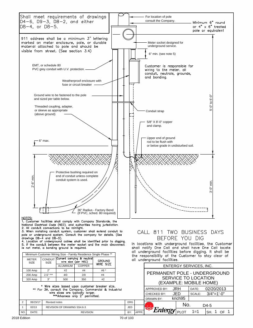
D4-5
end of conduit unless complete
Protective bushing required on
PVC grey conduit with U.V. protection.
3'-0" m
in.
5/8" X 8'-0" copper
Threaded coupling, adapter,
or sleeve as appropriate
111=1
3/4"=1'-0"
Upper end of ground
rod to be flush with
or below grade in undisturbed soil.
(above ground)
EMT, or schedule 80
2'-6" m
in.
6" max.
36" Radius - Factory Bend
consult the Company.
For location of pole
5'-0" to 6'-0"
JED
JRH
PERMANENT POLE - UNDERGROUND
SERVICE TO LOCATION
(EXAMPLE: MOBILE HOME)
Weatherproof enclosure with
fuse or circuit breaker
02/20/2013
krich95
and clamp.
REVISIONNO. DATE:
BY: APPR:
DATE:
SH. OF
SCALE:
APPROVED BY:
CHECKED BY:
DRAWN BY:
No.
PLOT
ENTERGY SERVICES, INC.
1 02/13 REVISION OF DRAWING SS4.6-3 JED
Conduit strap
(If PVC, sched. 80 required)
conduit system is used.
6" min. (see note 5)
Ground wire to be fastened to the pole
and sized per table below.
CONDUIT
Minimum Customer Wiring Size - Family Residence Single Phase **
200 Amp
320 Amp
100 Amp
SIZE
METER
4/0 2/0 #4 2.5" ***
3"
#4
COPPERALUMINUM
2"
SIZE
#2 #6 *
500 350 #2
Meter socket designed for
underground service.
2 06/15/17 Revised notes ERG
70 of 1032018 Edition

Existing
Company pole
M M
M
D4-6
DRAWN BY:
CHECKED BY:
APPROVED BY:
PLOT
krich95
JED
SCALE:
No.
1=1
DATE:
SH. OF
10/23/2012
1
None
1NO. DATE: REVISION APPR:BY:
M
1 10/12 JED
REVISION OF DRAWING SS4.6-4
JRH
12"
12"
15"
min.
3' min.
15"
min.
ENTERGY SERVICES, INC.
206/15/17 ERG
Revised Meter pole Set Correctly Details
71 of 1032018 Edition

COPPER
72 of 1032018 Edition
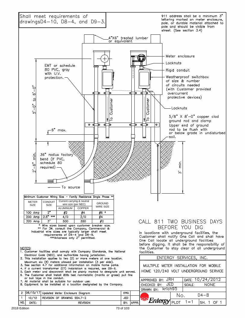
CONDUIT
SIZE
METER
Current carrying & neutral
wire size (per NEC)
COPPERALUMINUM
SIZE
GROUND
WIRE SIZE
73 of 1032018 Edition

D4-9
NONE
1=1 1 1
krich95
5/8" X 8'-0" copper clad
Upper end of ground
rod to be flush with
or below grade in undisturbed soil.
JED
JRH
of circuits needed
of size & number
Weatherproof switch box
over current protective devices)
(with Customer provided
Meter enclosure
Locknuts
Rigid conduit
Locknuts
10/31/2012
5'-0" to 6'-0"
5' m
in.
NOTES:
1. Customer facilities shall comply with Company Standards, the National Electrical
Code (NEC), and authorities having jurisdiction.
2. This installation applies to two (2) or more meters at one location. Maximum six (6)
meters allowed per installation (3 per side).
3. See section 4.7 for additional information on mobile home parks.
4. Each meter and disconnect shall be plainly marked to designate unit served.
5. All material shall be suitable for outdoor use.
6. Equipment to be installed at a location designated by the Company.
7. Additional pole height may be required to maintain proper clearance. (See section 7.3)
8. Customer Installed minimum 1/2" galvanized eye bolt with 2" x 2" square washer
recommended. Service Pole for service wires from Company to meter only.
9. If Customer decides to distribute overhead, a separate pole from Service Pole shall be
used.
or equivalent
4"X6" treated lumber
911 address shall be a minimum 3" lettering
marked on meter enclosure, pole, or durable
material attached to pole and should be
visible from street. (See section 3.4)
MULTIPLE METER SERVICE FOR
MOBILE HOME 120/240 VOLT
OVERHEAD SERVICE
18'-0" m
in. (see note 7)
19'-6" (see note 7)
20'-0" m
in. (see note 7)
Service Pole (See note 9)
To C
ustom
er
(see note 2)
(see note 2)
To C
ustom
er
In locations with underground facilities, the
Customer shall notify One Call and shall
have One Call locate all underground
facilities before digging. It shall be the
responsibility of the Customer to stay clear
of all underground facilities.
ground rod and clamp
Minimum Customer Wiring Size - Residence Single Phase **
CONDUIT
100 Amp
320 Amp
200 Amp
SIZE
METER
#6 *#21.5" #4
2/02"
3"
4/0 #4
COPPER
Current carrying & neutral
wire size (per NEC) *
ALUMINUM
SIZE
GROUND
WIRE SIZE
350500 #2
Shall meet requirements of drawings
D4-10 and D9-2.
(See note 8)
74 of 1032018 Edition
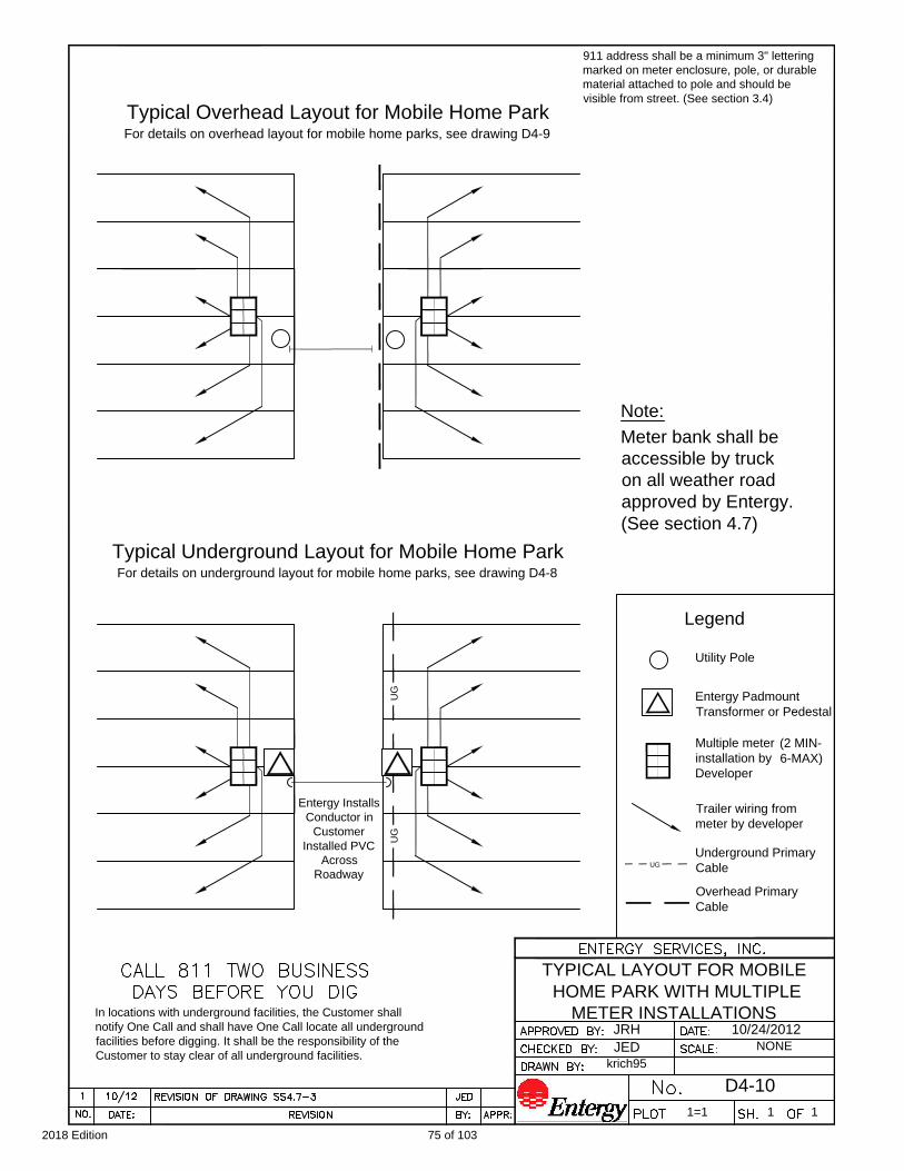
D4-10
NONE
1=1 1 1
krich95
JED
JRH 10/24/2012
TYPICAL LAYOUT FOR MOBILE
HOME PARK WITH MULTIPLE
METER INSTALLATIONS
Legend
Entergy Padmount
Transformer or Pedestal
Multiple meter
installation by
Developer
Trailer wiring from
meter by developer
UG
UG
Typical Underground Layout for Mobile Home Park
For details on underground layout for mobile home parks, see drawing D4-8
Typical Overhead Layout for Mobile Home Park
For details on overhead layout for mobile home parks, see drawing D4-9
UG
Underground Primary
Cable
Overhead Primary
Cable
Entergy Installs
Conductor in
Customer
Installed PVC
Across
Roadway
Utility Pole
911 address shall be a minimum 3" lettering
marked on meter enclosure, pole, or durable
material attached to pole and should be
visible from street. (See section 3.4)
In locations with underground facilities, the Customer shall
notify One Call and shall have One Call locate all underground
facilities before digging. It shall be the responsibility of the
Customer to stay clear of all underground facilities.
(2 MIN-
6-MAX)
Note:
Meter bank shall be
accessible by truck
on all weather road
approved by Entergy.
(See section 4.7)
75 of 1032018 Edition

CAUTION :
Connection points, when such
obstructions interfere with an
overhead service, may need to
be moved or converted to
underground (if possible), at
the customers expense.
Notes:
1. NEVER build structures under or over existing electrical lines or facilities. Check
with the Company for clearances.
2. Contact Company for clearances prior to pool construction.
3. See Section 9.4 for meter location. Connection point shall be pre-approved by the
Company.
4. See TABLE for maximum recommended service lengths. Longer lengths than those
in the table may require the Company to install an additional pole. This may involve
additional cost (typically $1500 or more), to the customer.
5. The Customer is responsible for clearing and maintaining all right of way.
D7-1
krich95
JED
1=1
01/09/2013
1
None
1
OVERHEAD SERVICE
INSTALLATION DETAILS
CORRECT CONNECTION POINT
Existing
Company
pole
INCORRECT CONNECTION POINT
HOME
POOL
TREE
BUILDING
Connection
point
Existing
Company
pole
INCORRECT CONNECTION POINT
Connection
point
Existing
Company
pole
HOME
Existing
Company
pole
SEE CAUTION
Maximum Recommended
Distance
Length
40'320
Amps
100
200
100'
75'
The Company will not install an electrical facility over a pool, building, shed, or deck.
TABLE
Existing
Company
power line
Existing
Company
power line
Existing
Company
power line
Existing
Company
power line
Connection point
within 3 ft. of front
of building on side
closest to pole
JRH
METER CLEARANCES
CAUTION:
No gas
meters
within a 3'
radius of
meter
enclosure.
No
fences,
clear
shrubs,
etc.
Meter
Socket
In locations with underground facilities, the Customer shall notify One
Call and shall have One Call locate all underground facilities before
digging. It shall be the responsibility of the Customer to stay clear of
all underground facilities.
PORCH
SEE CAUTION
HOME
PORCH
POOL
TREE
BUILDING
See note 2
D
E
C
K
Right of way for power line shall be on customer's land or customer shall get right of way from property owner.
SEE CAUTION
EMPTY LOT
MAY BE
BUILT UPON IN
FUTURE
PORCH
Connection
point within 3 ft.
of front of
building
INCORRECT CONNECTION POINT
SEE CAUTION
Wrong side of building for connection.
Overhead
cable
Overhead
cable
Overhead
cable
Overhead
cable
15"
MIN.
15"
MIN.
3'
MIN.
HOME
PORCH
See note 2
See note 2
76 of 1032018 Edition

12'-0" P
edestrians or R
estricted T
raffic only (see note 5)
5'-0" to 6'-0"
Mast support
5/8" X 8'-0" copper clad ground rod and clamp.
10/24/2012
1/8"=1'-0"
1=1 1 1
D7-2
JED
JRH
krich95
Minimum mounting height
for point of attachment
Upper end of ground rod to be flush with or
See note 2
See Maximum Recommended Distance
Point of Attachment (Minimum 1/2" galvanized eye bolt
recommended or other suitable attachment). (See
Notes 2, 5 and 6)
3' min.
working
clearance
(see
drawing
D7-1)
Ground wire attached to wall
911 address shall be a minimum 3"
lettering marked on structure, or meter
enclosure and should be visible from
street.
Minimum Customer Wiring Size - Residence Single Phase
CONDUIT
100 Amp
320 Amp
200 Amp
SIZE
METER
#6 #21.5" #4
2/02"
3"
4/0 #4
COPPER
Current carrying & neutral
wire size (per NEC)
ALUMINUM
SIZE
COPPER
GROUND
WIRE SIZE
350500#2
NOTES:
1. Customer facilities shall comply with Company Standards, the
National Electrical Code (NEC), and authorities having jurisdiction.
2. Customer shall install meter enclosure, conduit, weatherhead,
point of attachment and conductor to point of attachment.
3. A minimum of 3'-0" of each conductor shall extend from the top of
the service mast. The neutral shall be marked with white tape at both
ends. Neutral can be bare.
4. Main breaker should be within 2'-0" of meter. Outside wall is
recommended.
5. Clearance. (See Section 7.3)
a. Point of attachment shall be either accessible to Company's
bucket truck or have enough surface (such as wall or building
structure) and sufficient ground space.
b. Additional height may be required to maintain clearance.
c. Point of attachment can be no higher than 21'.
d. Minimum 10'-0" height to bottom of drip loop allowed when
all traffic under wire does not exceed 8'-0" height.
6. No telephone or cable attachment allowed on mast (NEC).
7. Any Service greater than 200 amps, consult the Company.
Shall meet requirements of drawings D7-1 and D9-2.
Amps
320
200
100
75'
40'
Length
100'
Maximum Recommended
Distance
below grade in undisturbed soil.
14
'-0
" M
in
(S
ee
n
ote
5
)
13
'-6
" m
in
. - 2
1' m
ax. (S
ee
n
ote
5
)
77 of 1032018 Edition

(See notes 2, 3 and 7)
Point of attachment
3' m
in. - 5' m
ax.
4'-0" max.
5/8" X 8'-0" copper clad ground rod
01/09/2013
None
1=1 1 1
D7-3
NOTES:
JED
JRH
krich95
and clamp. Upper end of ground rod
to be flush with or below grade
5'-0" to 6'-0"
(See note 5)
1. Customer facilities shall comply with Company Standards, the
National Electrical Code, and authorities having jurisdiction.
2. Customer shall install meter enclosure, conduit, weatherhead,
point of attachment and conductor to point of attachment.
3. A minimum of 3'-0" of each conductor shall extend from the top of
the service mast. The neutral shall be marked with white tape at both
ends. Neutral can be bare.
4. Main breaker should be within 2'-0" of meter. Outside wall is
recommended.
5. Distance from fascia to center of mast to be 4'-0" max. NEC. Only
rigid metal or IMC conduit can be used above the roof. Guying or
bracing of the mast may be required. See drawing D2-1.
6. Clearance. (See Section 7.3)
a. Point of attachment shall be either accessible to Company's
bucket truck or have enough surface (such as wall or building
structure) and sufficient ground space.
b. Additional height may be required to maintain clearance.
c. Point of attachment can be no higher than 21'.
d. Minimum 10'-0" height to bottom of drip loop allowed when all
traffic under wire does not exceed 8'-0" height.
7. No telephone or cable attachment allowed on mast (NEC).
8. Any Service greater than 200 amps, consult the Company.
See Maximum Recommended Distance
Maximum Recommended
Distance
Length
40'320
Amps
100
200
100'
75'
Ground wire
attached to wall
3' min.
working
clearance
(S
ee note 5)
Minimum Customer Wiring Size - Residence Single Phase
CONDUIT
100 Amp
320 Amp
200 Amp
SIZE
METER
#6#21.5" #4
2/02"
3"
4/0 #4
COPPER
Current carrying & neutral
wire size (per NEC)
ALUMINUM
SIZE
COPPER
GROUND
WIRE SIZE
350500 #2
911 address shall be a minimum 3" lettering
marked on structure, or meter enclosure and
should be visible from street.
Shall meet requirements of
drawings D7-1 and D9-2.
14
'-0
" m
in
. (S
ee
n
ote
6
)
13
'-6
" m
in
.- 2
1'-0
" m
ax. (S
ee
n
ote
6
)
12
'-0
" P
ed
estria
ns o
r R
estricte
d T
ra
ffic o
nly (S
ee
n
ote
6
)
in undisturbed soil.
78 of 1032018 Edition
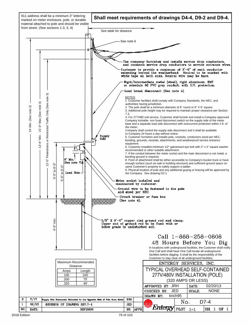
4'-0" m
in.
5'-0" to 6'-0"
11
1=1
D7-4
NONEJED
JRH 02/20/13
(320 AMPS OR LESS)
krich95
See note 6
NOTES:
1. Customer facilities shall comply with Company Standards, the NEC, and
authorities having jurisdiction.
2. The pole shall be a minimum diameter of 6" round or 6" X 6" square.
3. Additional pole height may be required to maintain proper clearance per Section
7.3.
4. For 277/480 volt service, Customer shall furnish and install a Company approved
Company lockable, non fused disconnect switch on the supply side of the meter
base and a separate load side disconnect with overcurrent protection within 2 ft. of
the meter.
Company shall control the supply side disconnect and it shall be available
to Company 24 hours a day without notice.
5. Customer furnishes and installs pole, conduits, conductors sized per NEC,
bonding, grounds, neutrals, attachments, and weatherproof service entrance
equipment.
6. Customer installed minimum 1/2" galvanized eye bolt with 2" x 2" square washer
recommended or other suitable attachment.
7. If the conduit between the meter socket and the main disconnect is not metal, a
bonding ground is required.
8. Point of attachment shall be either accessible to Company's bucket truck or have
enough surface (such as wall or building structure) and sufficient ground space on
same Customer's property to safely support a ladder.
9. Physical location of pole and any additional guying or bracing will be approved by
the Company. See drawing D2-1.
See table for distance
5'-0" to 6'-0"
Maximum Recommended
Distance
Length
40'320
Amps
100
200
100'
75'
911 address shall be a minimum 3" lettering
marked on meter enclosure, pole, or durable
material attached to pole and should be visible
from street. (See sections 1-3, 3, 4)
Shall meet requirements of drawings D4-4, D9-2 and D9-4.
In locations with underground facilities, the Customer shall notify
One Call and shall have One Call locate all underground
facilities before digging. It shall be the responsibility of the
Customer to stay clear of all underground facilities.
14
'-M
in
. (S
ee
n
ote
3
)
13
'-6
" M
in
. - 2
1'-0
" M
ax (S
ee
n
ote
3
)
12
'-0
" P
ed
estria
ns o
r R
estricte
d T
ra
ffic O
nly (S
ee
n
ote
3
)
79 of 1032018 Edition

111=1
D7-4A
NONEKWS
JRH 07/07/17
(320 AMPS OR LESS)
ERG
NOTES:
1. Customer facilities shall comply with Company Standards, the NEC, and authorities having jurisdiction.
2. Additional height may be required to maintain proper clearance per Section 7.3.
3. For 277/480 volt service, Customer shall furnish and install a Company approved Company lockable, non
fused disconnect switch on the supply side of the meter base and a separate load side disconnect with
overcurrent protection within 2 ft. of the meter.
Company shall control the supply side disconnect and it shall be available
to Company 24 hours a day without notice.
4. Customer furnishes and installs conduits, conductors sized per NEC, bonding, grounds, neutrals,
attachments, and weatherproof service entrance equipment.
5. Customer installed minimum 1/2" galvanized eye bolt with 2" x 2" square washer recommended or other
suitable attachment.
6. If the conduit between the meter socket and the main disconnect is not metal, a bonding ground is required.
7. Point of attachment shall be either accessible to Company's bucket truck or have enough surface (such as
wall or building structure) and sufficient ground space.
911 address shall be a minimum 3" lettering
marked on meter enclosure and shall be visible
from street. (See sections 1-3, 3, 4)
Shall meet requirements of drawings D9-2 and D9-4.
Maximum Recommended
Distance
Length
40'320
Amps
100
200
100'
75'
14'-0" M
in. (S
ee note 2)
13'-6"-M
in.-21'-0"-M
ax. (see note 2)
12'-0" P
edestrians or R
estriced T
raffic only (see note 3)
5'-0" to 6'-0"
5'-0" to 6'-0"
SEE NOTE 5
80 of 1032018 Edition

D8-1
krich95
JED
1=1
10/24/2012
1
None
1
UNDERGROUND SERVICE INSTALLATION
DETAILS & CLEARANCES
UNDERGROUND REQUIREMENTS
FOR PAVED AREAS
Connection
point
UNDERGROUND CLEARANCE
FOR SWIMMING POOL
UNDERGROUND FACILITIES
CLEARANCES
From shrubs, trees, buildings, fences, decks etc.
DO NOT BLOCK ACCESS
TO ELECTRICAL
FACILITIES
Electrical
facilities and
lines can never
be within 5' of a
pool
3' min.
3'
min.
3'
min.
12' min.
(lock side)
3' min.
15"
min.
METER CLEARANCES & LOCATION
15"
min.
Meter
Socket
No gas
meter,
fences or
anything
else
5' min.
CAUTION:
No gas
meters
within a 3'
radius of
meter
enclosure.
JRH
See note 2
In locations with underground facilities, the Customer shall notify
One Call and shall have One Call locate all underground facilities
before digging. It shall be the responsibility of the Customer to
stay clear of all underground facilities.
5' min.
SERVICE CABLE IS NOT ALLOWED BELOW A BUILDING.
Minimum Customer Wiring Size - Residence Single Phase **
CONDUIT
100 Amp
320 Amp
200 Amp
SIZE
METER
#6 #42" #2
4/02.5" *
3"
2/0 #4
ALUMINUM
Current carrying & neutral
wire size (per NEC)
COPPER
SIZE
GROUND
WIRE SIZE
500350#2
Notes:
1.The Customer is responsible for clearing and maintaining all right of way.
2. NEVER build structures under or over existing electrical lines or facilities.
Check with the Company for clearances.
3. Contact Company for clearances prior to pool construction.
4. Connection point shall be pre-approved by the Company.
5. Transformers must meet requirements of drawing D10-1.
6. The Customer shall bear the cost of conduit and its installation.
7. Underground service/conduit should be installed separated by not less 24" of well
tamped earth from other utilities.
8. Conduit color shall be electrical gray or black with red stripes (for continuous
below ground conduit). Conduits above the ground and transition elbow or conduit
from underground to above ground, shall be schedule 80 PVC or equivalent.
Generally, non-metallic conduit installed totally below grade shall be at least
Schedule 40 PVC or equivalent. In certain cases, concrete encasement may be
required according to Drawings D8-2 and D8-7. All conduits, elbows, fittings, etc.
shall be UL approved with an U. L. label.
81 of 1032018 Edition

Pedestal (See pull box
detail and notes 1 and 2)
Exact Meter locations
to be determined by
Company
STANDARD SERVICE INSTALLATION
JEDREVISION OF DRAWING SS8.6-110/121
Notes:
1. Customer shall consult with Company for location and type of
pedestal.
2. The Customer shall bear the cost of conduit and its installation.
ENTERGY SERVICES, INC.
PLOT
No.
DRAWN BY:
CHECKED BY:
APPROVED BY:
SCALE:
SH. OF
DATE:
APPR:BY:DATE:NO.
REVISION
Company facility
krich95
10/31/2012JRH
JED
CUSTOMER UNDERGROUND SERVICE
REQUIREMENTS FOR SECONDARY PHASE
TYPICAL CONDUIT SYSTEM
Company facility
Conduit run as
specified
NONE
D8-2
1=1 1 1
See note 2
STANDARD SERVICE INSTALLATION
In locations with underground facilities, the Customer shall notify One
Call and shall have One Call locate all underground facilities before
digging. It shall be the responsibility of the Customer to stay clear of
all underground facilities.
Ground
Level
TYPICAL PULL BOX PEDESTAL
Ground
Level
R
O
A
D
Conduit run as
specified
DRIVEWAY
FRONT OF
HOUSE
PEDESTAL REQUIRED IF:
CONDUIT LONGER THAN 200 FT. OR
CONDUIT HAS MORE THAN 3 BENDS
POLE
WITH PEDESTAL
INCLUDING RISER BENDS.
82 of 1032018 Edition

111=1
D8-3
NONE
DETAILS FOR TYPICAL UNDERGROUND
SERVICE AT HOUSE OR BUILDING
JED
JRH 11/06/2012
krich95
Note: Install conduit under meter
socket on opposite side of switch
CONDUIT PLACEMENT
OR
Note: Install conduit under meter
socket on opposite side of switch
Meter socket shall be designed for underground service installed and maintained by
Customer. Main breaker should be within 2'-0" of the meter. Outside wall recommended.
In locations with underground facilities, the Customer shall
notify One Call and shall have One Call locate all underground
facilities before digging. It shall be the responsibility of the
Customer to stay clear of all underground facilities.
SEE DRAWING D9-3 WIRING DIAGRAM
CONNECTIONS FOR UNDERGROUND
SELF CONTAINED METERS
See note 6
5/8" X 8'-0" copper clad
ground rod and clamp
5/8" X 12" steel dowels
Threaded coupling, adapter, or
sleeve as appropriate.
6" max.
2'-6" m
in.
See note 9
required when concrete
encased.
36" radius factory bend
(If PVC, schedule 80
required).
DIRECT BURIED SYSTEM
(See note 12)
IN CONDUIT SYSTEM
(See note 12)
6'-6" w
orking clearance
5'-0" m
in.-6'-0" m
ax.
clearance
3' working
(required)
When installing conduit system,
Customer shall extend conduit
to pole (Drawing D8-5) or to
Pedestal (Drawing D8-4).
Shall meet requirements of drawings
D8-1, D8-2 and D9-3.
in undisturbed soil.
83 of 1032018 Edition
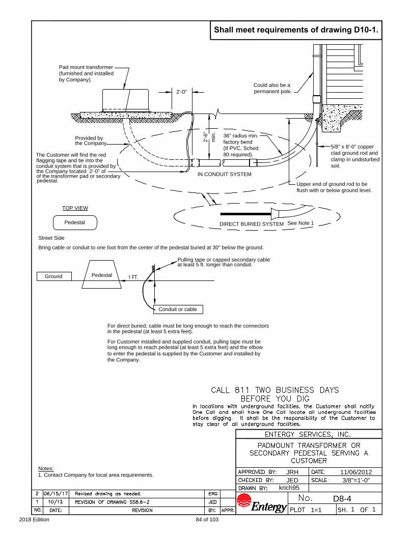
2'-6"
by Company).
(furnished and installed
Pad mount transformer
3/8"=1'-0"
D8-4
1=1
1 1
36" radius min.
Upper end of ground rod to be
flush with or below ground level.
JED
JRH 11/06/2012
krich95
min.
factory bend
(If PVC, Sched.
80 required).The Customer will find the red
Provided by
IN CONDUIT SYSTEM
DIRECT BURIED SYSTEM
2'-0"
Pedestal
TOP VIEW
Street Side
Bring cable or conduit to one foot from the center of the pedestal buried at 30" below the ground.
Ground
Pedestal
flagging tape and tie into the
conduit system that is provided by
the Company located 2'-0" of
of the transformer pad or secondary
pedestal.
the Company
Conduit or cable
Pulling tape or capped secondary cable
at least 5 ft. longer than conduit.
For direct buried, cable must be long enough to reach the connectors
in the pedestal (at least 5 extra feet).
For Customer installed and supplied conduit, pulling tape must be
long enough to reach pedestal (at least 5 extra feet) and the elbow
to enter the pedestal is supplied by the Customer and installed by
the Company.
See Note 1
Shall meet requirements of drawing D10-1.
Could also be a
permanent pole.
Notes:
1. Contact Company for local area requirements.
5/8" x 8'-0" copper
clad ground rod and
clamp in undisturbed
soil.
84 of 1032018 Edition

See note 2
Pole
Ground
111=1
D8-5
NONEJED
JRH 02/26/2013
krich95
7"
6"
2'-6" min.
See note 2
Could also be
meter on pole.
DIRECT BURIED SYSTEM
(See note 3)
IN CONDUIT SYSTEM
(See note 3)
TYPICAL UNDERGROUND SERVICE
FROM OVERHEAD SOURCE
In locations with underground facilities, the Customer shall notify One
Call and shall have One Call locate all underground facilities before
digging. It shall be the responsibility of the Customer to stay clear of
all underground facilities.
If pedestal present,
see drawing D8-4.
85 of 1032018 Edition
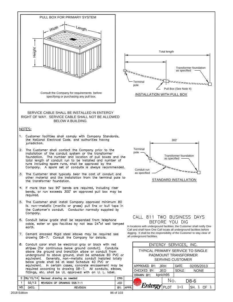
Total length
STANDARD INSTALLATION
pole
Terminal
Pull Box (See Note 4)
INSTALLATION WITH PULL BOX
SERVING CUSTOMER
Conduit run
as specified
Terminal
pole
Transformer foundation
as specified
PADMOUNT TRANSFORMER
111=1
D8-6
NONE
Transformer foundation
as specified
TYPICAL PRIMARY SERVICE TO SINGLE
300'
JED
JRH 02/05/2013
kprich95
Consult the Company for requirements before
specifying or purchasing any pull box.
PULL BOX FOR PRIMARY SYSTEM
He
ig
ht
In locations with underground facilities, the Customer shall notify One
Call and shall have One Call locate all underground facilities before
digging. It shall be the responsibility of the Customer to stay clear of
all underground facilities.
SERVICE CABLE SHALL BE INSTALLED IN ENTERGY
RIGHT OF WAY. SERVICE CABLE SHALL NOT BE ALLOWED
BELOW A BUILDING.
86 of 1032018 Edition
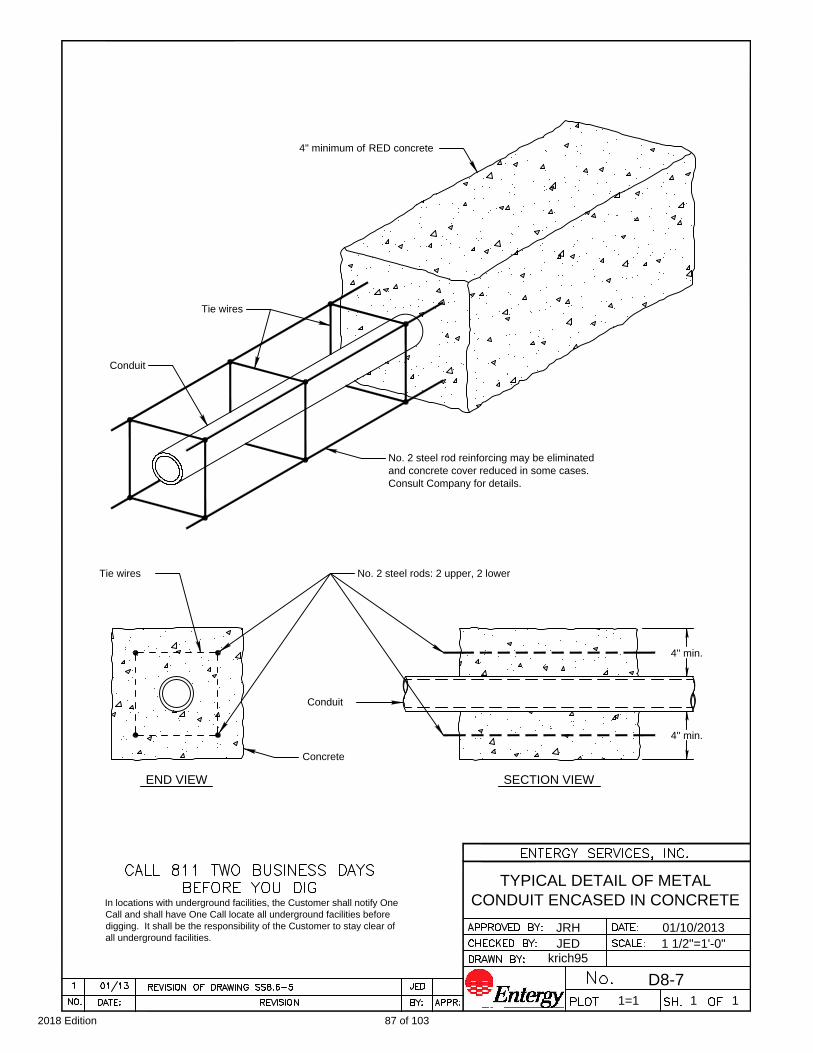
and concrete cover reduced in some cases.
No. 2 steel rod reinforcing may be eliminated
Conduit
4" min.
SECTION VIEWEND VIEW
Tie wires
Concrete
Conduit
No. 2 steel rods: 2 upper, 2 lower
111=1
D8-7
1 1/2"=1'-0"
4" min.
Consult Company for details.
Tie wires
JED
JRH 01/10/2013
krich95
TYPICAL DETAIL OF METAL
CONDUIT ENCASED IN CONCRETE
4" minimum of RED concrete
In locations with underground facilities, the Customer shall notify One
Call and shall have One Call locate all underground facilities before
digging. It shall be the responsibility of the Customer to stay clear of
all underground facilities.
87 of 1032018 Edition
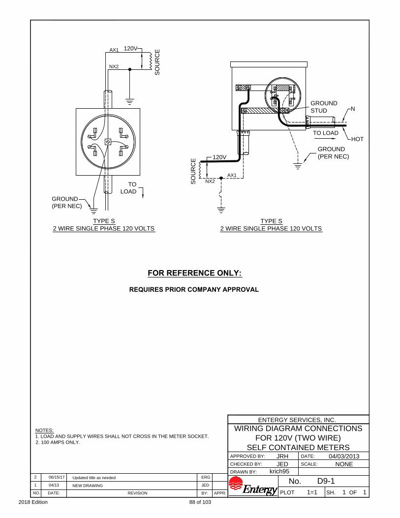
ENTERGY SERVICES, INC.
DRAWN BY:
CHECKED BY:
APPROVED BY:
PLOT
JRH
JED
krich95
SCALE:
1=1
DATE:
SH. OF
04/03/2013
NONE
1 1
TYPE S
2 WIRE SINGLE PHASE 120 VOLTS
NEW DRAWING
REVISIONDATE:
1
NO.
04/13
APPR:
JED
BY:
WIRING DIAGRAM CONNECTIONS
FOR 120V (TWO WIRE)
SELF CONTAINED METERS
NOTES:
1. LOAD AND SUPPLY WIRES SHALL NOT CROSS IN THE METER SOCKET.
2. 100 AMPS ONLY.
D9-1No.
GROUND
(PER NEC)
GROUND
STUD
TO LOAD
NX2
SO
UR
CE
AX1
120V
N
HOT
SO
UR
CE
AX1
NX2
120V
TO
LOAD
GROUND
(PER NEC)
TYPE S
2 WIRE SINGLE PHASE 120 VOLTS
FOR REFERENCE ONLY:
REQUIRES PRIOR COMPANY APPROVAL
Updated title as needed
206/15/17 ERG
88 of 1032018 Edition
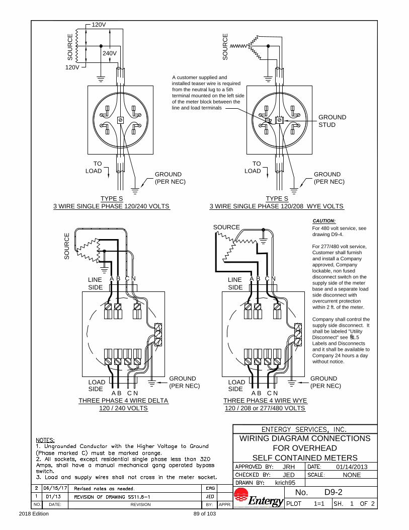
SO
UR
CE
120V
120V
240V
GROUND
STUD
SO
UR
CE
SOURCE
SO
UR
CE
LINE
A B C N A B C N
A B C N A B C N
LOAD LOAD
JRH
JED
krich95
1=1
01/14/2013
NONE
1 2
GROUND
(PER NEC)
GROUND
(PER NEC)
GROUND
(PER NEC)
TO
LOAD
TO
LOAD
SIDE
LINE
SIDE
SIDE SIDE
TYPE S
3 WIRE SINGLE PHASE 120/240 VOLTS
TYPE S
3 WIRE SINGLE PHASE 120/208 WYE VOLTS
THREE PHASE 4 WIRE DELTA
120 / 240 VOLTS
THREE PHASE 4 WIRE WYE
120 / 208 or 277/480 VOLTS
REVISIONDATE:NO.APPR:BY:
WIRING DIAGRAM CONNECTIONS
FOR OVERHEAD
SELF CONTAINED METERS
D9-2No.
A customer supplied and
installed teaser wire is required
from the neutral lug to a 5th
terminal mounted on the left side
of the meter block between the
line and load terminals
For 480 volt service, see
drawing D9-4.
For 277/480 volt service,
Customer shall furnish
and install a Company
approved, Company
lockable, non fused
disconnect switch on the
supply side of the meter
base and a separate load
side disconnect with
overcurrent protection
within 2 ft. of the meter.
Company shall control the
supply side disconnect. It
shall be labeled "Utility
Disconnect" see 1.5
Labels and Disconnects
and it shall be available to
Company 24 hours a day
without notice.
GROUND
(PER NEC)
s
s
CAUTION:
89 of 1032018 Edition

JRH
JED
krich95
1=1
01/10/2013
NONE
2 2
TYPE S
3 WIRE SINGLE PHASE 120/240 VOLTS
TYPE S
3 WIRE SINGLE PHASE 120/208 WYE VOLTS
THREE PHASE 4 WIRE DELTA
120 / 240 VOLTS
THREE PHASE 4 WIRE WYE
120 / 208 or 277/480 VOLTS
REVISIONDATE:NO.APPR:BY:
WIRING DIAGRAM CONNECTIONS
FOR UNDERGROUND
SELF CONTAINED METERS
Ungrounded Conductor with the
Higher Voltage to Ground (Phase
marked C) must be marked
orange (NEC 110.15 & 230.56)
Note: Install conduit
under meter socket on
opposite side of switch
Note: Install conduit
under meter socket on
opposite side of switch
CONDUIT PLACEMENT
Meter socket shall be designed for underground service
(installed and maintained by customer)
OR
GROUND
(PER NEC)
SO
UR
CE
LINE
SO
UR
CE
Right SideLeft Side
D9-3No.
A customer
supplied and
installed teaser
wire is required
from the neutral
lug to a 5th
terminal
mounted on
the left side of
the meter block
between the
line and load
terminals.
120V
120V
240V
GROUND
STUD
TO LOAD
GROUND
STUD
TO LOAD
SO
UR
CE
ABCN
TO LOAD
AB
CN
LINE
GROUND
ABCN
TO LOAD
AB
CN
GROUND
(PER NEC)
SO
UR
CE
GROUND (PER NEC)
For 480 volt service, see
drawing D9-5.
For 277/480 volt service,
Customer shall furnish and install
a Company approved, Company
lockable, non fused disconnect
switch on the supply side of the
meter base and a separate load
side disconnect with overcurrent
protection within 2 ft. of the meter.
Company shall control the supply
side disconnect. It shall be labeled
"Utility Disconnect" see 1.5 Labels
and Disconnects and it shall be
(PER NEC)
available to Company 24 hours
a day without notice.
s
s
Caution:
90 of 1032018 Edition

OVERHEAD
JED
01/14/2013
krich95
111=1
NONE
D9-4
ENTERGY SERVICES, INC.
Phase to phase = 480 Volts
Phase to neutral = 277 Volts
480 Volts
480 Volts
480 Volts
A
C
B
N
A
C
B
N
277 Volts
277 Volts
277 Volts
N A B C
LOAD
N BA C
N CA B
REVISIONNO. DATE:
BY: APPR:
DATE:
SH. OF
SCALE:
CEA NO.
APPROVED BY:
CHECKED BY:
DRAWN BY:
No.
PLOT
NOTES:
1. Consult the Company.
JRH
COMPANY
CONTROLLED
2 FT. OR LESS
For 480 volt service, see
drawing D9-2.
For 277/480 volt service,
Customer shall furnish and install
a Company approved, Company
lockable, non fused disconnect
switch on the supply side of the
meter base and a separate load
side disconnect with overcurrent
protection within 2 ft. of the meter.
Company shall control the supply
side disconnect. It shall be labeled
"Utility Disconnect" see 1.5 Labels
and Disconnects and it shall be
available to Company 24 hours
a day without notice.
s
s
Caution:
LINE
91 of 1032018 Edition
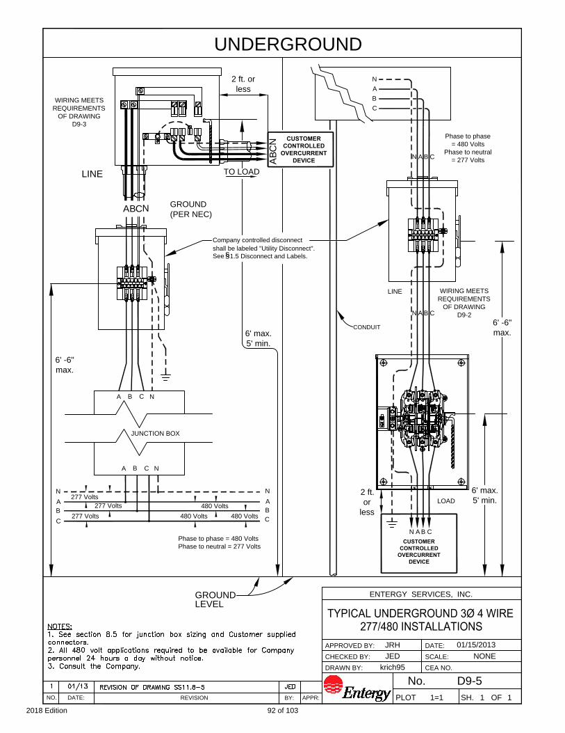
JED
01/15/2013
krich95
111=1
NONE
D9-5
ENTERGY SERVICES, INC.
REVISIONNO. DATE:
BY: APPR:
DATE:
SH. OF
SCALE:
CEA NO.
APPROVED BY:
CHECKED BY:
DRAWN BY:
No.
PLOT
JRH
UNDERGROUND
Phase to phase = 480 Volts
Phase to neutral = 277 Volts
C
B
A
N
480 Volts
480 Volts
480 Volts
A CB N
A
C
B
N
277 Volts
277 Volts
277 Volts
JUNCTION BOX
NA B C
LINE
GROUND
(PER NEC)
ABCN
TO LOAD
AB
CN
Phase to phase
= 480 Volts
Phase to neutral
= 277 Volts
N A B C
N B
CONDUIT
C
N CA B
C
B
A
N
A
6' -6"
max.
6' max.
5' min.
GROUND
Company controlled disconnect
shall be labeled "Utility Disconnect".
s
s
LEVEL
See 1.5 Disconnect and Labels.
CUSTOMER
CONTROLLED
OVERCURRENT
DEVICE
CUSTOMER
CONTROLLED
OVERCURRENT
DEVICE
6' max.
5' min.
6' -6"
max.
LOAD
2 ft.
or
less
LINEWIRING MEETS
REQUIREMENTS
OF DRAWING
D9-2
WIRING MEETS
REQUIREMENTS
OF DRAWING
D9-3
2 ft. or
less
92 of 1032018 Edition

CT
BONDING SCREW REQUIRED
MAIN
DISC
#4 CU MIN.
CTCT
ENTERGY SERVICES, INC.
NONE
1=1 1 1
11/15/2012
REVISIONNO. DATE:
BY: APPR:
DATE:
SH. OF
SCALE:
CEA NO.
APPROVED BY:
CHECKED BY:
DRAWN BY:
No.
PLOT
krich95
CT/PT arrangement for 277V/480V
CTCT
PT
PT
PT
H1 H2
X1 X2
H1 H1
DETAIL "A"
D9-6
H1
CT
CLEARANCE OVER ROADS, STREET, ALLEYS, AND PARKING LOTS SUBJECT TO
TRUCK TRAFFIC. SEE 7-3.
JRH
JED
TABLE 9.1.3: GUIDELINE FOR METER TRANSFORMER
ENCLOSURE WITH MULTIPLE CIRCUITS
93 of 1032018 Edition

MAIN
DISC
CEA NO.
SCALE:
DATE:
REVISION APPR:BY:
CHECKED BY:
APPROVED BY:
DRAWN BY:
PLOT
krich95
No.
SH. OF
02/26/2013
NONE
1=1 1 1DATE:NO.
ENTERGY SERVICES, INC.
D9-7
DETAIL "A"
H1
CT/PT arrangement for 277V/480V
CT
H1
X1 X2
H2
PT
PT
PT
H1
CT CT
H1
JED
JRH
TABLE 9.1.3: GUIDELINE FOR METER TRANSFORMER
ENCLOSURE WITH MULTIPLE CIRCUITS
94 of 1032018 Edition

CUSTOMER OWNED MULTIPLE METER
NONE
1=1 1 1
krich95
OVERHEAD SERVICE
(FIELD ASSEMBLED)
Wireway or buss duct
Locknuts
Rigid conduit
Meter enclosure
(with Customer provided
over current
protective devices)
Locknuts
Weatherproof switchbox
of size & number
of circuits needed
DETAIL "B"
DETAIL "A"
Weather proof
Neutral conductor
Wireway or
duct
6'-6"
Weatherhead
Conductors to extend
3'-0" from weatherhead
Conduit straps
Main disconnect
(see note 3)
Weatherproof wireway
or buss duct
LOT
No.
2A
note 4
See
Weather proof
threaded hub
threaded
hub
6" Dia. or 6" x 6"
(min.) treated poles
JED
JDS
Locknuts
Rigid conduit
01/15/2013
D9-8
See detail "A"
Protective bushing
required on all conduit
6" min.
See
detail "B"
13'-6" m
in. - 21' m
ax. (S
ee note 10)
5'-0" to 6'-0"
14'-0" M
in. (S
ee note 10)
12'-0" P
edestrians R
estricted T
raffic O
nly
4'-0" (M
in.)
95 of 1032018 Edition
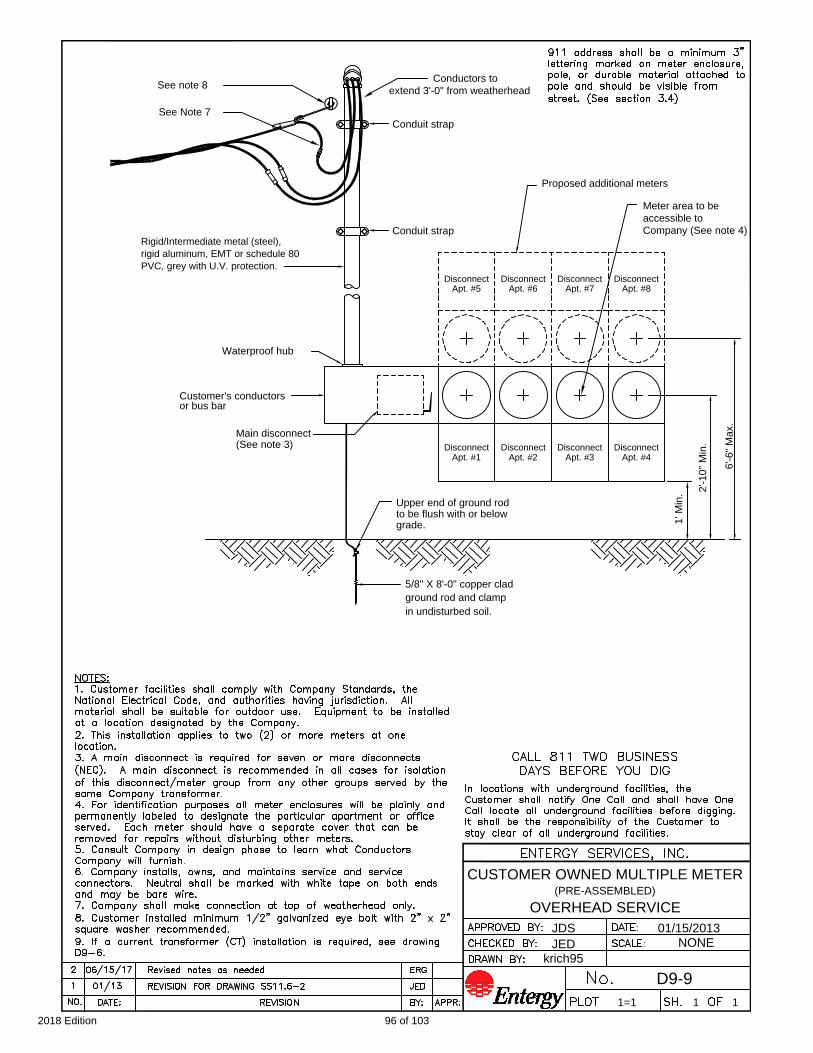
rigid aluminum, EMT or schedule 80
PVC, grey with U.V. protection.
Rigid/Intermediate metal (steel),
Conductors to
extend 3'-0" from weatherhead
Waterproof hub
Main disconnect
(See note 3)
Customer's conductors
or bus bar
D9-9
OVERHEAD SERVICE
(PRE-ASSEMBLED)
CUSTOMER OWNED MULTIPLE METER
krich95
JED
JDS
1=1
ground rod and clamp
5/8" X 8'-0" copper clad
01/15/2013
NONE
1 1
Company (See note 4)
Meter area to be
Proposed additional meters
Disconnect
Apt. #8
accessible to
Disconnect
Apt. #4
Disconnect
Apt. #2
Upper end of ground rod
Disconnect
Apt. #6
to be flush with or below
Apt. #1
Disconnect
grade.
Disconnect
Apt. #5
Apt. #3
Disconnect
Disconnect
Apt. #7
Conduit strap
2'-10" M
in.
6'-6" M
ax.
See note 8
See Note 7
Conduit strap
1' M
in.
in undisturbed soil.
96 of 1032018 Edition

CUSTOMER OWNED MULTIPLE METER
D9-10
NONE
1=1 1 1
krich95
UNDERGROUND SERVICE
(FIELD ASSEMBLED)
To source
JED
JRH 04/03/2013
6" max.
2'-6" m
in.
5'-0" to 6'-0"
3' m
in.
1' - 0" m
in.
6"-M
in.
97 of 1032018 Edition
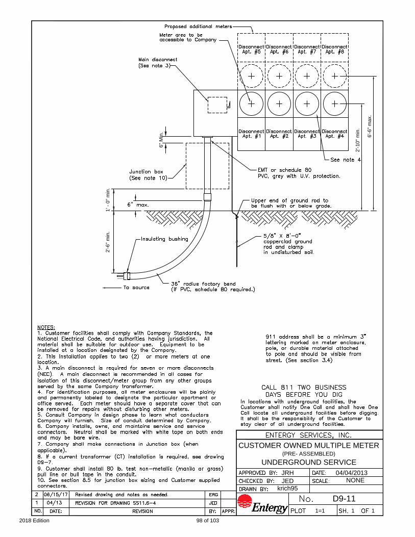
2'-6" m
in.
(PRE- ASSEMBLED)
UNDERGROUND SERVICE
D9-11
CUSTOMER OWNED MULTIPLE METER
krich95
JED
JRH
1=1
04/04/2013
NONE
1 1
2'-10" m
in.
6'-6" m
ax.
1' - 0" m
in.
6" M
in.
98 of 1032018 Edition

Disconnect
(See notes
Underground Main
JEDREVISION FOR DRAWING SS11.6-501/131
ENTERGY SERVICES, INC.
PLOT
No.
DRAWN BY:
CHECKED BY:
APPROVED BY:
SCALE:
SH. OF
DATE:
APPR:BY:DATE:NO.
REVISION
5'-0" to 6'-0"
6'-6" m
ax.
2'-10" m
in.
and clamp
ground rod
01/15/2013JRH
JED
grade.
to be flush with or below
Upper end of ground rod
(See note 7)
Disconnect
Neutral
5/8" X 8'-0"
copperclad
or bus duct
Weatherproof wireway
(See note 7)
Overhead main disconnect
krich95
111=1
NONE
D9-12
1'-0" m
in.
1'-0" m
in.
Company
Controlled
Disconnect
(See note 4)
Customer
Controlled
3 and 4)
Utility
Disconnect
for
Customer #1
ERGUpdated title, notes and added dimensions as needed.06/15/172
6"-M
in.
in undisturbed soil.
Utility
Disconnect
for
Customer #2
Utility
Disconnect
for
Customer #3
Utility
Disconnect
for
Customer #4
See note 4
99 of 1032018 Edition
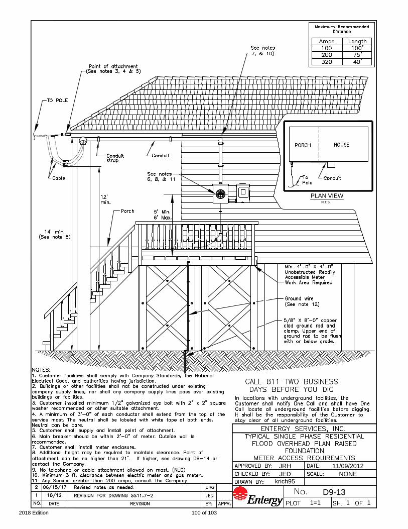
krich95
11/09/2012JRH
JED NONE
D9-13
1=1 1 1
PLAN VIEW
N.T.S.
100 of 1032018 Edition

krich95
11/07/2012JRH
JED NONE
D9-14
1=1 1 1
30"
101 of 1032018 Edition

ENTERGY SERVICES, INC.
D10-1
NONE
1=1 1 1
krich95
11/29/2012
REVISIONNO. DATE:
BY: APPR:
DATE:
SH. OF
SCALE:
APPROVED BY:
CHECKED BY:
DRAWN BY:
No.
PLOT
10' (min.)
10' (min.)
Se
e ta
ble
1
10' (min.)
20' (min.)
FRONT ELEVATION
20' (min.)
10' (min.)
10' (min.)
See table 1
"A1"
TABLE 1
11/29/121REFERENCE DRAWING UG1004011 JED
JED
JRH
8/17/992REFERENCE DRAWING TO DAS01281 DAT
5/23/063 ADDED NOTE 9 DAT
06/15/174
Updated notes as needed. ERG
102 of 1032018 Edition
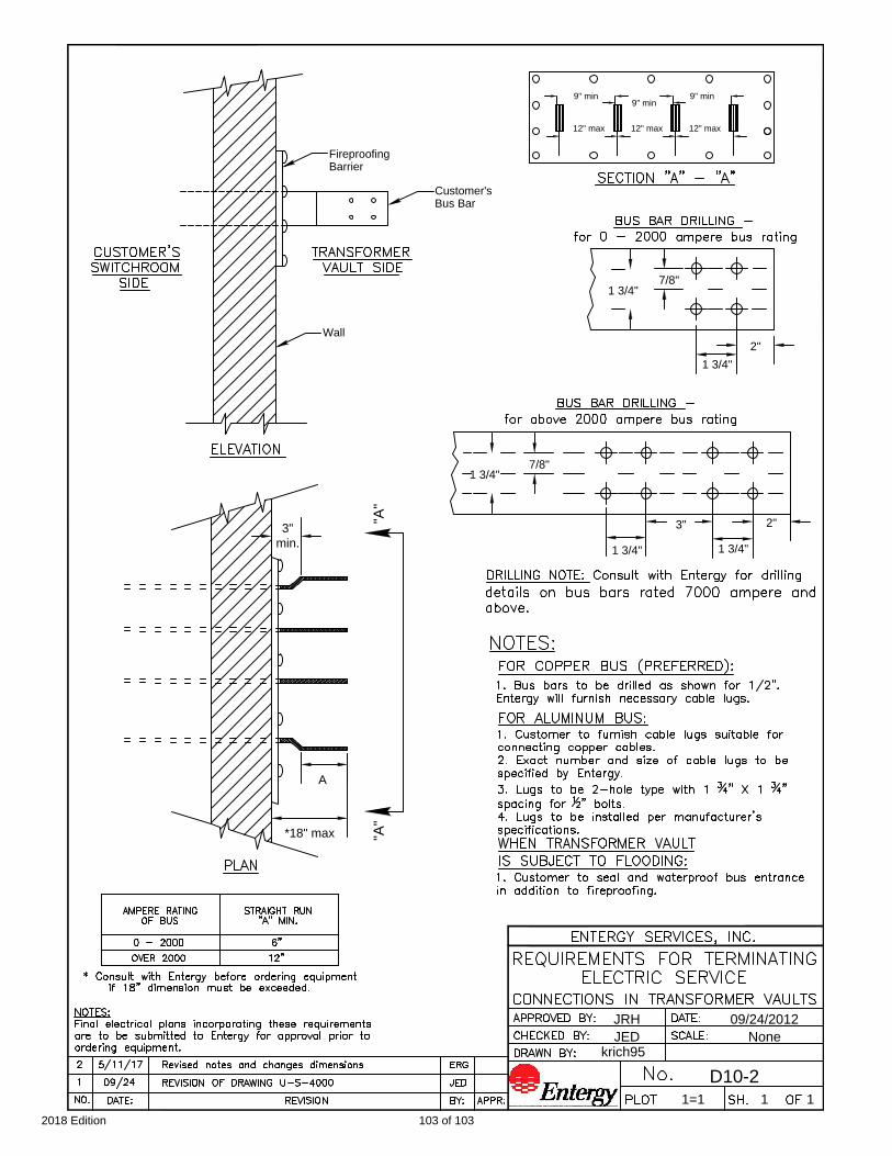
111=1
D10-2
NoneJED
JRH 09/24/2012
krich95
2"
1 3/4"
3"
1 3/4"
7/8"
1 3/4"
2"
1 3/4"
7/8"
1 3/4"
9" min
9" min
9" min
12" max 12" max 12" max
"A
"
Fireproofing
Barrier
Customer's
Bus Bar
Wall
*18" max
A
"A
"
3"
min.
103 of 1032018 Edition


