Nonlinear Analysis of Steel-concrete Composite Beams Curved in Plan
AASHTOWare BrDR 6.8
3D FEM Analysis Tutorial Curved Steel 3D Example
3DFEM3 - Curved Steel 3D Example
Last Modified: 9/1/2016 1
3DFEM3 - Curved Steel 3D Example
Last Modified: 9/1/2016 2
3DFEM3 - Curved Steel 3D Example
Last Modified: 9/1/2016 3
Topics Covered
3D analysis of a three span curved steel rolled beam bridge
Diaphragm definitions
3D analysis settings
3D model
This example describes entering a curved steel rolled beam structure in BrDR and performing a 3D FEM analysis.
Import the file “3DFEM3 - Curved Steel 3D Example.xml” and open its Bridge Workspace. This bridge is the I-
Girder design example presented in the appendix of the AASHTO Guide Specifications for Horizontally Curved Steel
Girder Highway Bridges, 2003.
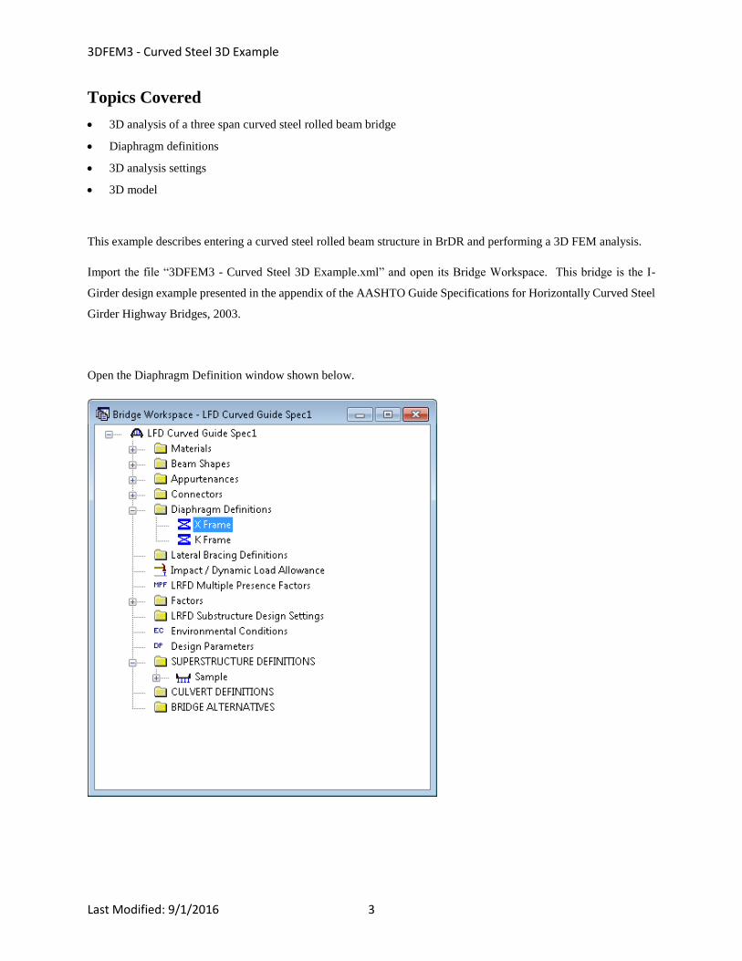
Open the Diaphragm Definition window shown below.
3DFEM3 - Curved Steel 3D Example
Last Modified: 9/1/2016 4
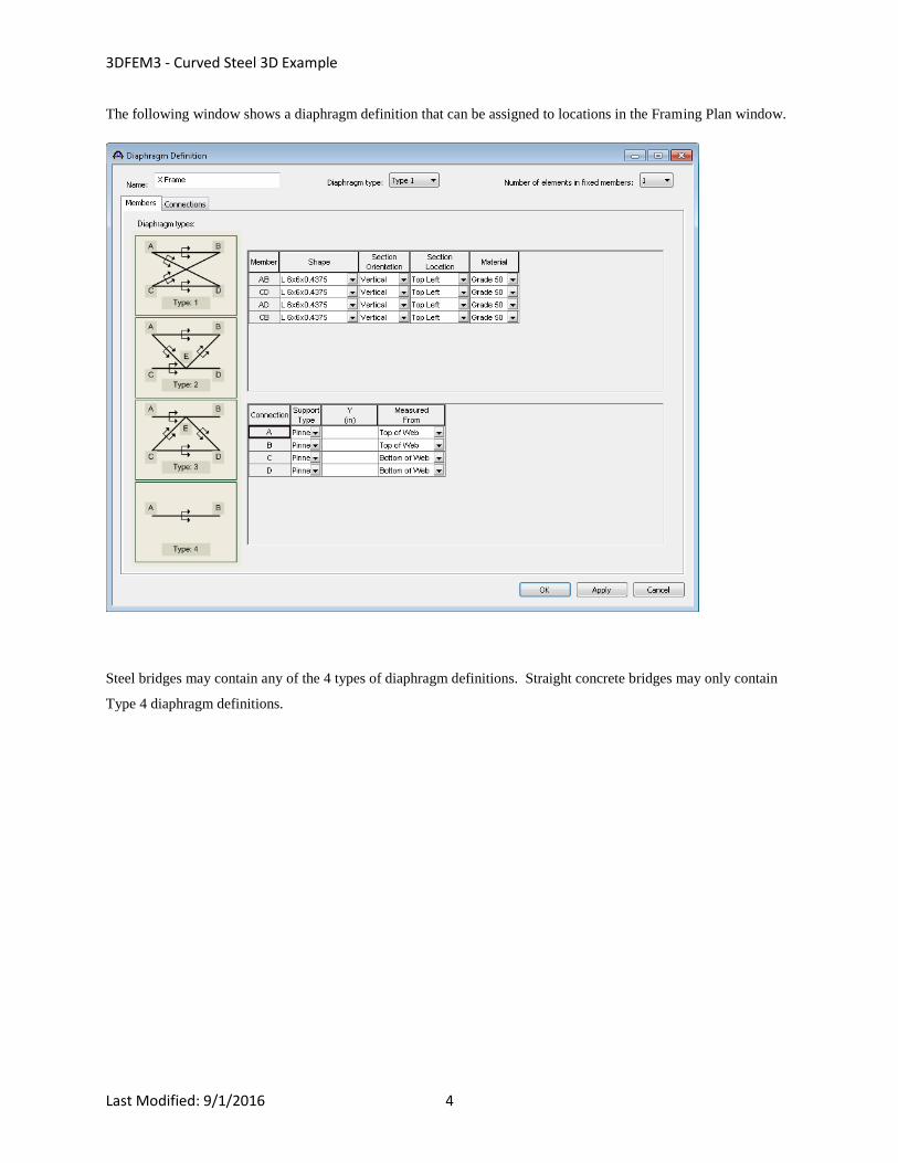
The following window shows a diaphragm definition that can be assigned to locations in the Framing Plan window.
Steel bridges may contain any of the 4 types of diaphragm definitions. Straight concrete bridges may only contain
Type 4 diaphragm definitions.
3DFEM3 - Curved Steel 3D Example
Last Modified: 9/1/2016 5
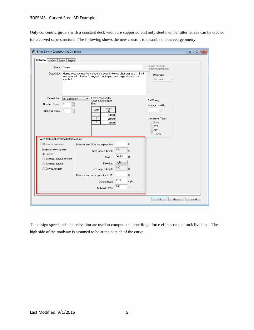
Only concentric girders with a constant deck width are supported and only steel member alternatives can be created
for a curved superstructure. The following shows the new controls to describe the curved geometry.
The design speed and superelevation are used to compute the centrifugal force effects on the truck live load. The
high side of the roadway is assumed to be at the outside of the curve.
3DFEM3 - Curved Steel 3D Example
Last Modified: 9/1/2016 6
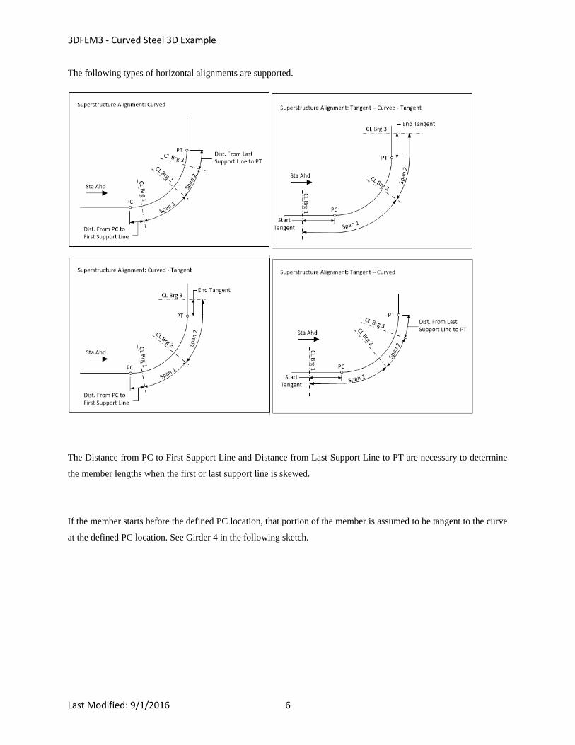
The following types of horizontal alignments are supported.
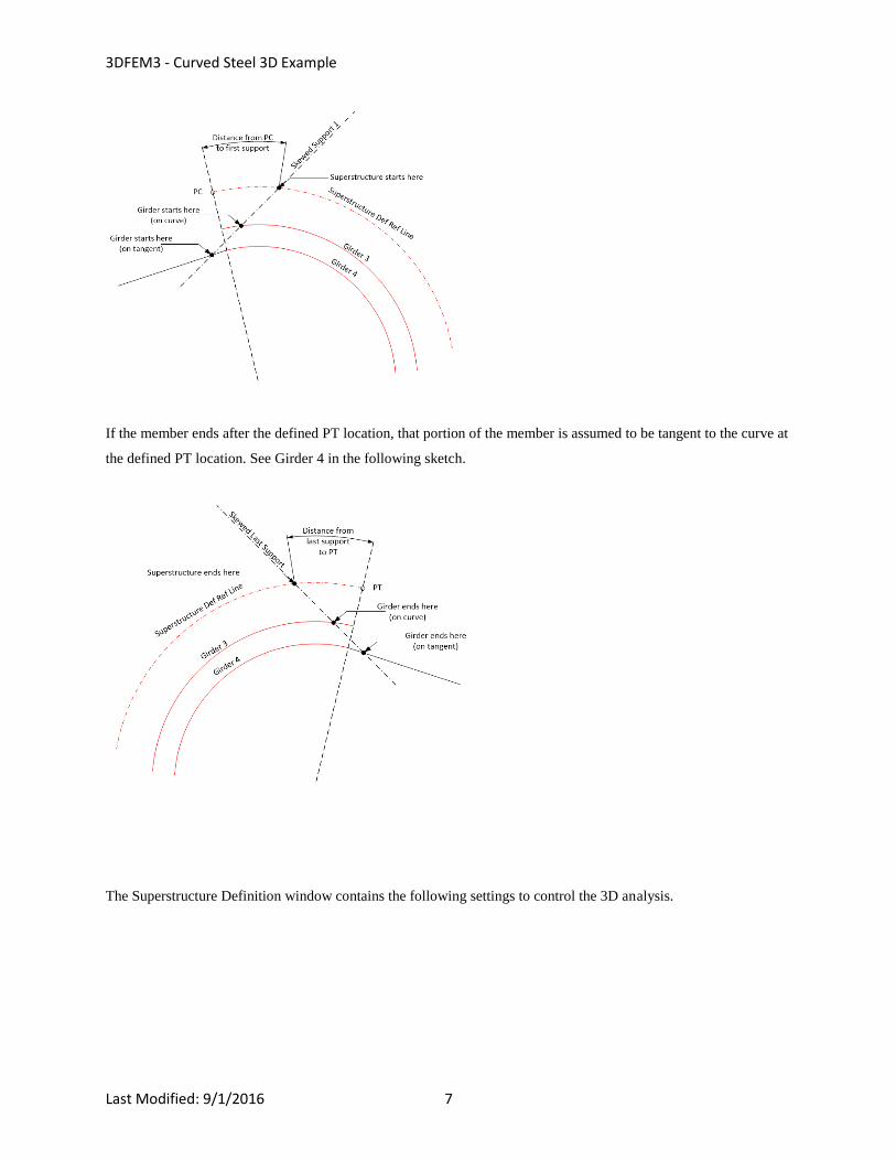
The Distance from PC to First Support Line and Distance from Last Support Line to PT are necessary to determine
the member lengths when the first or last support line is skewed.
If the member starts before the defined PC location, that portion of the member is assumed to be tangent to the curve
at the defined PC location. See Girder 4 in the following sketch.
3DFEM3 - Curved Steel 3D Example
Last Modified: 9/1/2016 7
If the member ends after the defined PT location, that portion of the member is assumed to be tangent to the curve at
the defined PT location. See Girder 4 in the following sketch.
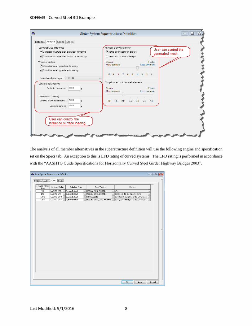
The Superstructure Definition window contains the following settings to control the 3D analysis.
3DFEM3 - Curved Steel 3D Example
Last Modified: 9/1/2016 8
The analysis of all member alternatives in the superstructure definition will use the following engine and specification
set on the Specs tab. An exception to this is LFD rating of curved systems. The LFD rating is performed in accordance
with the “AASHTO Guide Specifications for Horizontally Curved Steel Girder Highway Bridges 2003”.
3DFEM3 - Curved Steel 3D Example
Last Modified: 9/1/2016 9
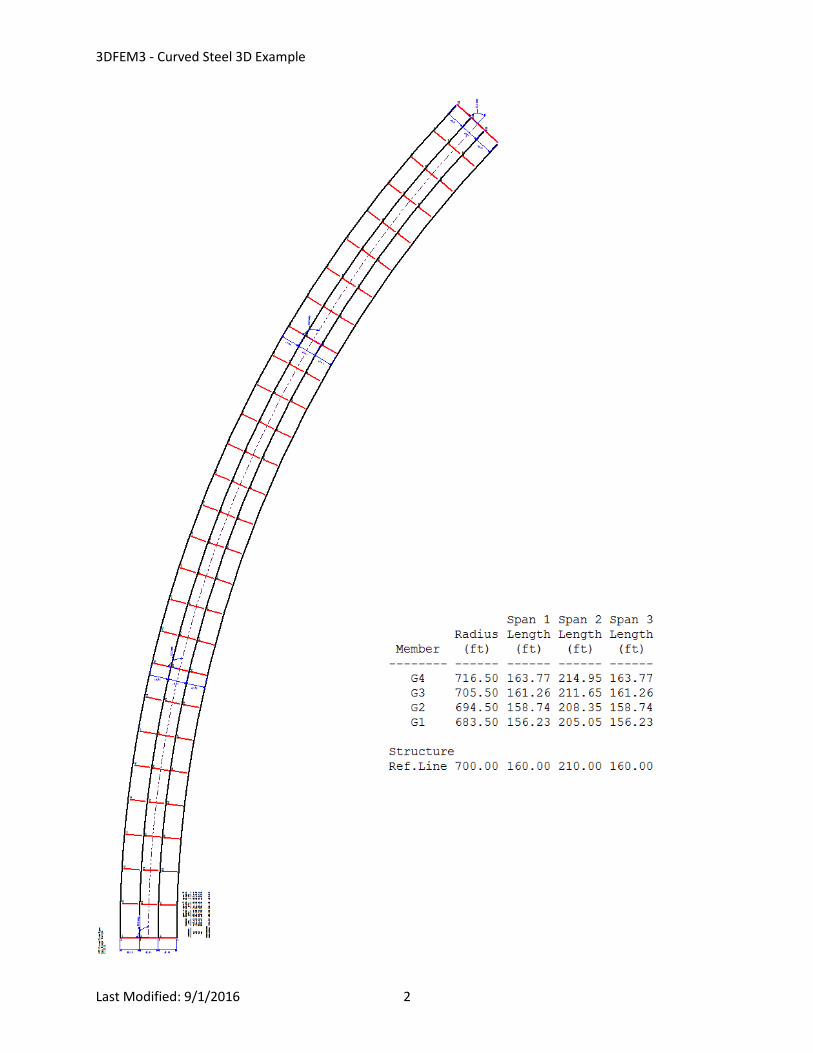
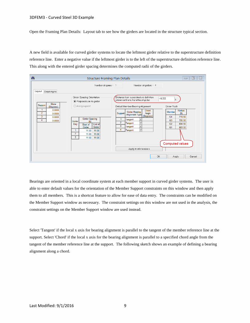
Open the Framing Plan Details: Layout tab to see how the girders are located in the structure typical section.
A new field is available for curved girder systems to locate the leftmost girder relative to the superstructure definition
reference line. Enter a negative value if the leftmost girder is to the left of the superstructure definition reference line.
This along with the entered girder spacing determines the computed radii of the girders.
Bearings are oriented in a local coordinate system at each member support in curved girder systems. The user is
able to enter default values for the orientation of the Member Support constraints on this window and then apply
them to all members. This is a shortcut feature to allow for ease of data entry. The constraints can be modified on
the Member Support window as necessary. The constraint settings on this window are not used in the analysis, the
constraint settings on the Member Support window are used instead.
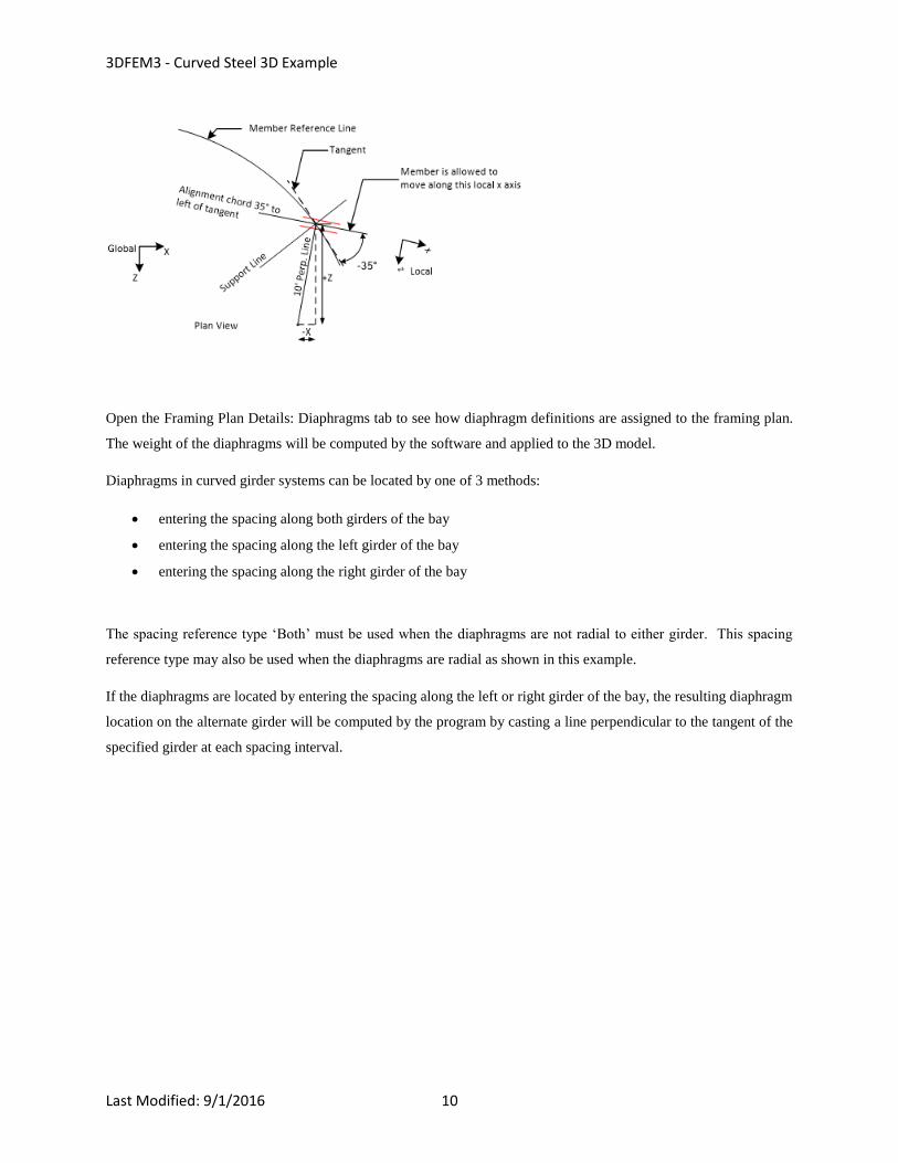
Select 'Tangent' if the local x axis for bearing alignment is parallel to the tangent of the member reference line at the
support. Select 'Chord' if the local x axis for the bearing alignment is parallel to a specified chord angle from the
tangent of the member reference line at the support. The following sketch shows an example of defining a bearing
alignment along a chord.
3DFEM3 - Curved Steel 3D Example
Last Modified: 9/1/2016 10
Open the Framing Plan Details: Diaphragms tab to see how diaphragm definitions are assigned to the framing plan.
The weight of the diaphragms will be computed by the software and applied to the 3D model.
Diaphragms in curved girder systems can be located by one of 3 methods:
entering the spacing along both girders of the bay
entering the spacing along the left girder of the bay
entering the spacing along the right girder of the bay
The spacing reference type ‘Both’ must be used when the diaphragms are not radial to either girder. This spacing
reference type may also be used when the diaphragms are radial as shown in this example.
If the diaphragms are located by entering the spacing along the left or right girder of the bay, the resulting diaphragm
location on the alternate girder will be computed by the program by casting a line perpendicular to the tangent of the
specified girder at each spacing interval.

3DFEM3 - Curved Steel 3D Example
Last Modified: 9/1/2016 11
A wizard is available to create the diaphragm locations for the user. The wizard is not available if any of the
supports are skewed.
3DFEM3 - Curved Steel 3D Example
Last Modified: 9/1/2016 12
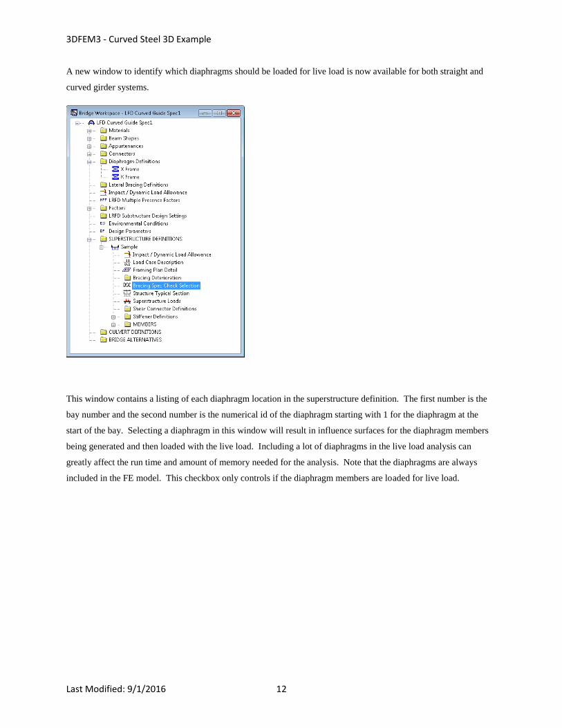
A new window to identify which diaphragms should be loaded for live load is now available for both straight and
curved girder systems.
This window contains a listing of each diaphragm location in the superstructure definition. The first number is the
bay number and the second number is the numerical id of the diaphragm starting with 1 for the diaphragm at the
start of the bay. Selecting a diaphragm in this window will result in influence surfaces for the diaphragm members
being generated and then loaded with the live load. Including a lot of diaphragms in the live load analysis can
greatly affect the run time and amount of memory needed for the analysis. Note that the diaphragms are always
included in the FE model. This checkbox only controls if the diaphragm members are loaded for live load.
3DFEM3 - Curved Steel 3D Example
Last Modified: 9/1/2016 13
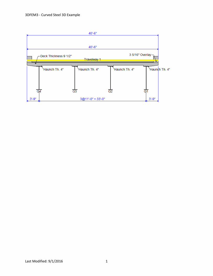
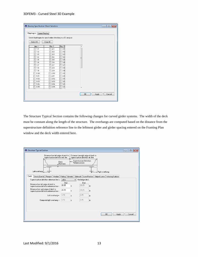
The Structure Typical Section contains the following changes for curved girder systems. The width of the deck
must be constant along the length of the structure. The overhangs are computed based on the distance from the
superstructure definition reference line to the leftmost girder and girder spacing entered on the Framing Plan
window and the deck width entered here.

3DFEM3 - Curved Steel 3D Example
Last Modified: 9/1/2016 14
Note in the schematic that for this example bridge, the travelway has been entered to the out to out deck width
instead of between the parapets. This was done to match how the structure was loaded in the appendix of the
AASHTO Guide Spec so that results of live loading could be compared between BrDR and the results published in
the AASHTO Guide Spec.
Open the Member Supports window to see how bearings can be oriented for curved girder systems. For curved
girder systems bearings are oriented in a local coordinate system at each member support. Select 'Tangent' if the
local x axis for bearing alignment is parallel to the tangent of the member reference line at the support. Select
'Chord' if the local x axis for the bearing alignment is parallel to a specified chord angle from the tangent of the
member reference line at the support. The following sketch shows an example of defining a bearing alignment
along a chord.

3DFEM3 - Curved Steel 3D Example
Last Modified: 9/1/2016 15
3DFEM3 - Curved Steel 3D Example
Last Modified: 9/1/2016 16
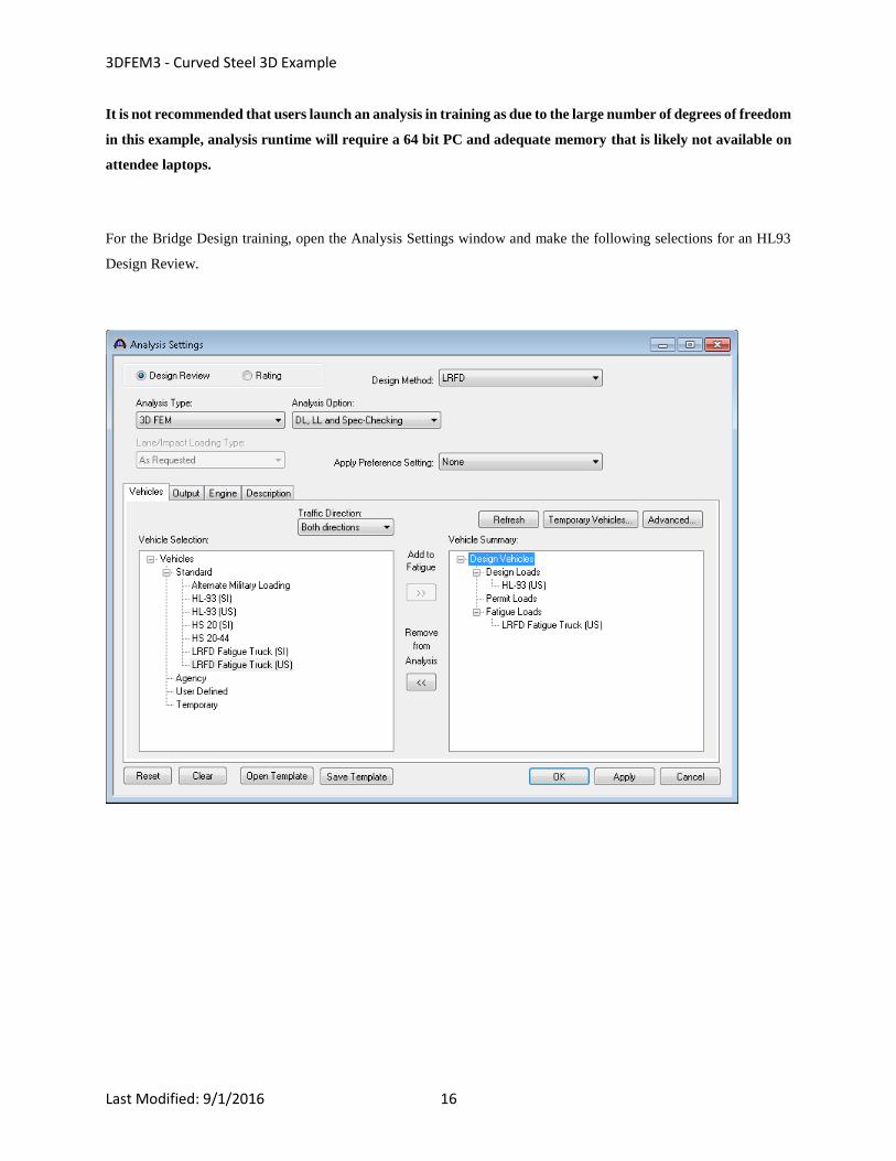
It is not recommended that users launch an analysis in training as due to the large number of degrees of freedom
in this example, analysis runtime will require a 64 bit PC and adequate memory that is likely not available on
attendee laptops.
For the Bridge Design training, open the Analysis Settings window and make the following selections for an HL93
Design Review.

3DFEM3 - Curved Steel 3D Example
Last Modified: 9/1/2016 17
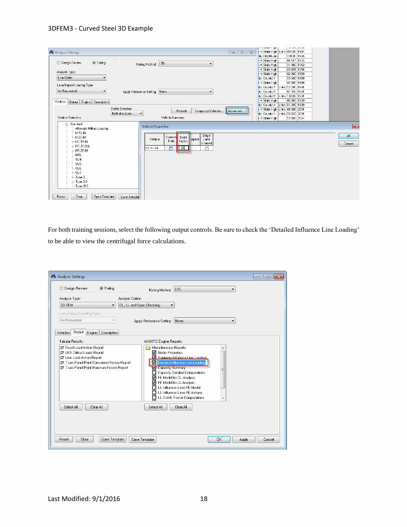
For the Bridge Rating training, open the Analysis Settings window and make the following selections.
The example in the AASHTO Guide Specification is for an HS25 loading. To produce this loading, enter a scale
factor of 1.25 in the Advanced Vehicle Properties window.
3DFEM3 - Curved Steel 3D Example
Last Modified: 9/1/2016 18
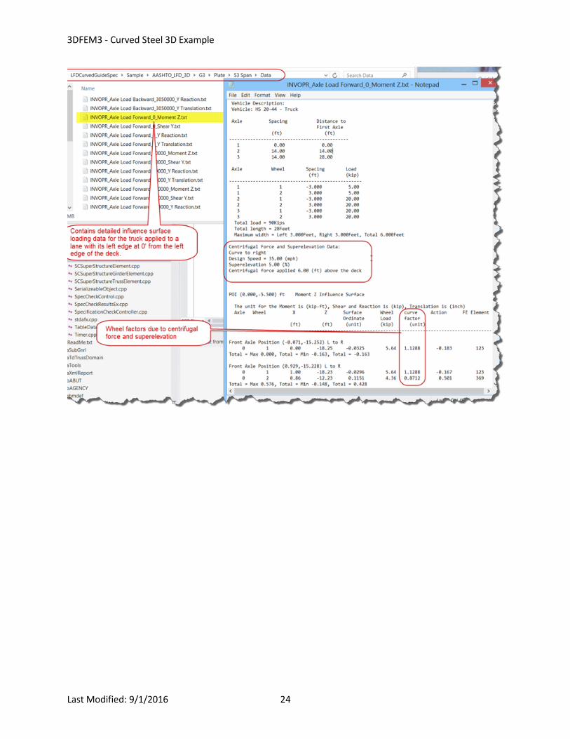
For both training sessions, select the following output controls. Be sure to check the ‘Detailed Influence Line Loading’
to be able to view the centrifugal force calculations.
3DFEM3 - Curved Steel 3D Example
Last Modified: 9/1/2016 19
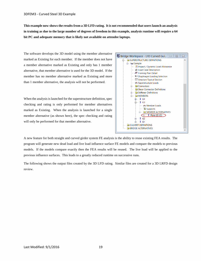
This example now shows the results from a 3D LFD rating. It is not recommended that users launch an analysis
in training as due to the large number of degrees of freedom in this example, analysis runtime will require a 64
bit PC and adequate memory that is likely not available on attendee laptops.
The software develops the 3D model using the member alternative
marked as Existing for each member. If the member does not have
a member alternative marked as Existing and only has 1 member
alternative, that member alternative is used for the 3D model. If the
member has no member alternative marked as Existing and more
than 1 member alternative, the analysis will not be performed.
When the analysis is launched for the superstructure definition, spec
checking and rating is only performed for member alternatives
marked as Existing. When the analysis is launched for a single
member alternative (as shown here), the spec checking and rating
will only be performed for that member alternative.
A new feature for both straight and curved girder system FE analysis is the ability to reuse existing FEA results. The
program will generate new dead load and live load influence surface FE models and compare the models to previous
models. If the models compare exactly then the FEA results will be reused. The live load will be applied to the
previous influence surfaces. This leads to a greatly reduced runtime on successive runs.
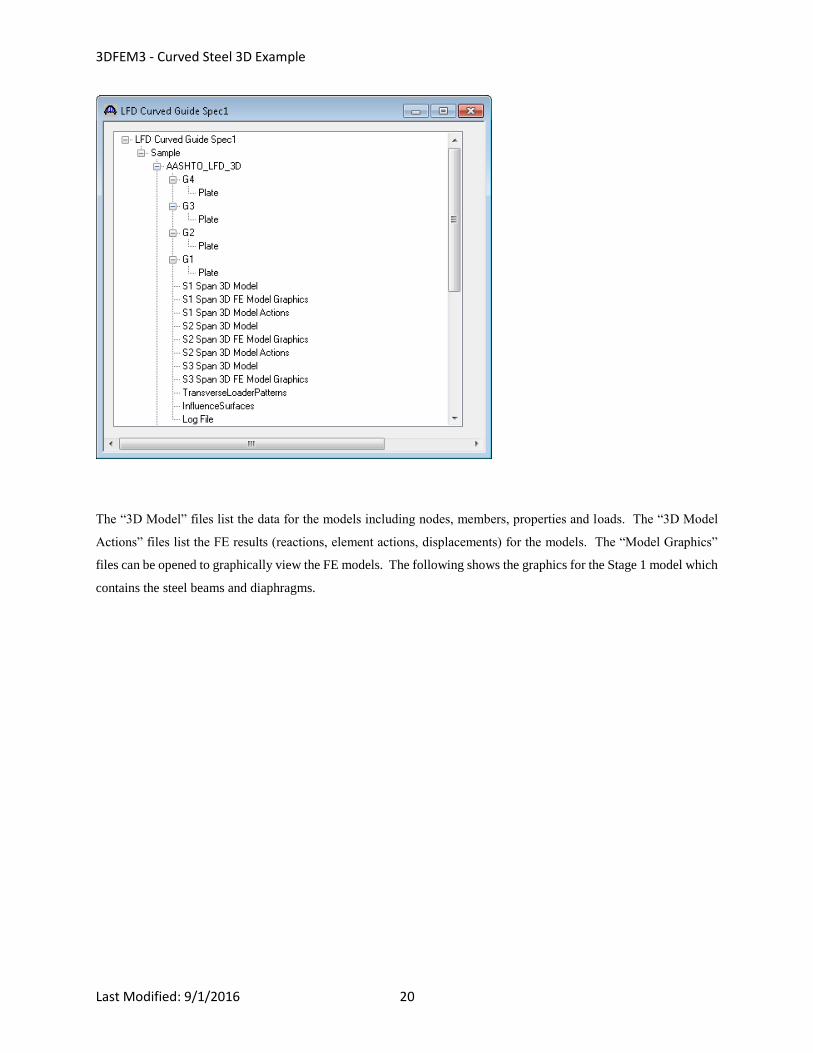
The following shows the output files created by the 3D LFD rating. Similar files are created for a 3D LRFD design
review.
3DFEM3 - Curved Steel 3D Example
Last Modified: 9/1/2016 20
The “3D Model” files list the data for the models including nodes, members, properties and loads. The “3D Model
Actions” files list the FE results (reactions, element actions, displacements) for the models. The “Model Graphics”
files can be opened to graphically view the FE models. The following shows the graphics for the Stage 1 model which
contains the steel beams and diaphragms.
3DFEM3 - Curved Steel 3D Example
Last Modified: 9/1/2016 21
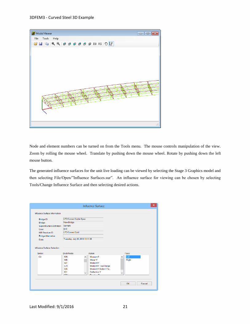
Node and element numbers can be turned on from the Tools menu. The mouse controls manipulation of the view.
Zoom by rolling the mouse wheel. Translate by pushing down the mouse wheel. Rotate by pushing down the left
mouse button.
The generated influence surfaces for the unit live loading can be viewed by selecting the Stage 3 Graphics model and
then selecting File/Open/”Influence Surfaces.sur”. An influence surface for viewing can be chosen by selecting
Tools/Change Influence Surface and then selecting desired actions.
3DFEM3 - Curved Steel 3D Example
Last Modified: 9/1/2016 22
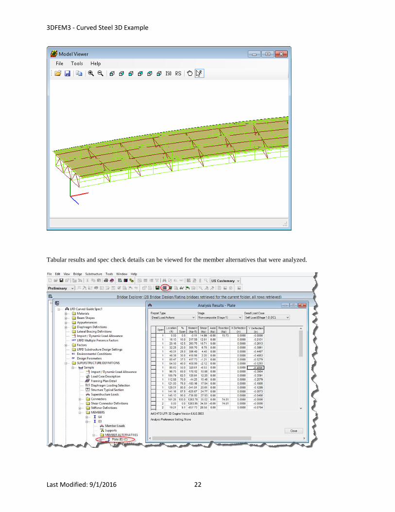
Tabular results and spec check details can be viewed for the member alternatives that were analyzed.

3DFEM3 - Curved Steel 3D Example
Last Modified: 9/1/2016 23
The results of the HS25 rating are shown below:
The centrifugal force effect calculations can be found in the detailed influence surface loading files found in the
following folder (of the Documents folder).
3DFEM3 - Curved Steel 3D Example
Last Modified: 9/1/2016 24
3DFEM3 - Curved Steel 3D Example
Last Modified: 9/1/2016 25
3D Model
The modeling techniques used are the result of a survey of researchers and practitioners and review of several software
packages.
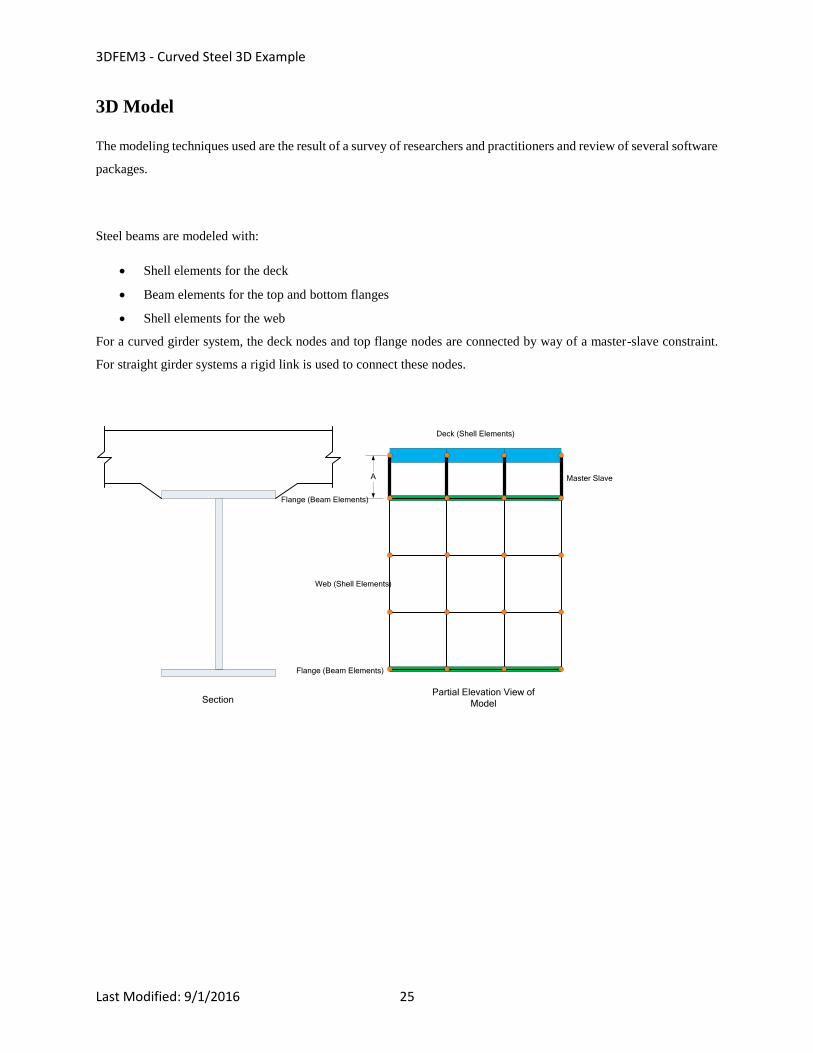
Steel beams are modeled with:
Shell elements for the deck
Beam elements for the top and bottom flanges
Shell elements for the web
For a curved girder system, the deck nodes and top flange nodes are connected by way of a master-slave constraint.
For straight girder systems a rigid link is used to connect these nodes.
Master Slave
Flange (Beam Elements)
Web (Shell Elements)
Flange (Beam Elements)
Deck (Shell Elements)
SectionPartial Elevation View of
Model
A
3DFEM3 - Curved Steel 3D Example
Last Modified: 9/1/2016 26
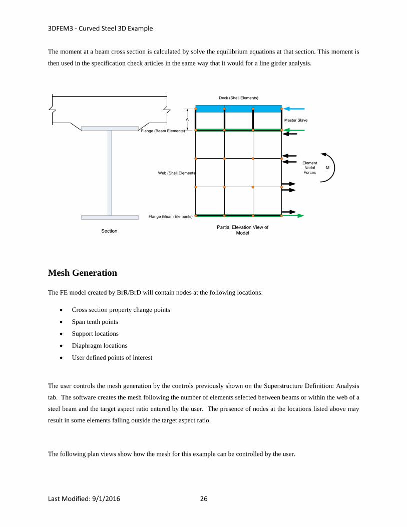
The moment at a beam cross section is calculated by solve the equilibrium equations at that section. This moment is
then used in the specification check articles in the same way that it would for a line girder analysis.
Master Slave
Flange (Beam Elements)
Web (Shell Elements)
Flange (Beam Elements)
Deck (Shell Elements)
M
Element
Nodal
Forces
SectionPartial Elevation View of
Model
A
Mesh Generation
The FE model created by BrR/BrD will contain nodes at the following locations:
Cross section property change points
Span tenth points
Support locations
Diaphragm locations
User defined points of interest
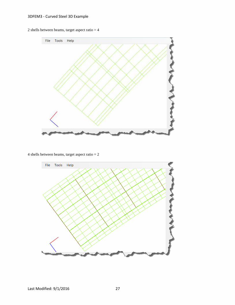
The user controls the mesh generation by the controls previously shown on the Superstructure Definition: Analysis
tab. The software creates the mesh following the number of elements selected between beams or within the web of a
steel beam and the target aspect ratio entered by the user. The presence of nodes at the locations listed above may
result in some elements falling outside the target aspect ratio.
The following plan views show how the mesh for this example can be controlled by the user.
3DFEM3 - Curved Steel 3D Example
Last Modified: 9/1/2016 27
2 shells between beams, target aspect ratio = 4
4 shells between beams, target aspect ratio = 2
3DFEM3 - Curved Steel 3D Example
Last Modified: 9/1/2016 28
Loading
The program computes all of the dead loads acting on the beam including the self-weight of the beam, user defined
appurtenances on the structure typical section, wearing surfaces, diaphragms and user defined member loads.
Composite dead loads are applied directly to the deck shells in the 3D model in their actual location. They are not
distributed to the girders based on the choices available in the Superstructure Loads window.
The Stage 3 FE model is loaded with unit loads at each deck node within the travelway to generate influence surfaces
for the beam. Lane positions and combinations are determined based on the travelway and the transverse loading
parameters set by the user on the Superstructure Definition: Analysis Settings tab. The influence surfaces are then
loaded with the selected vehicles to find the maximum live load effects.
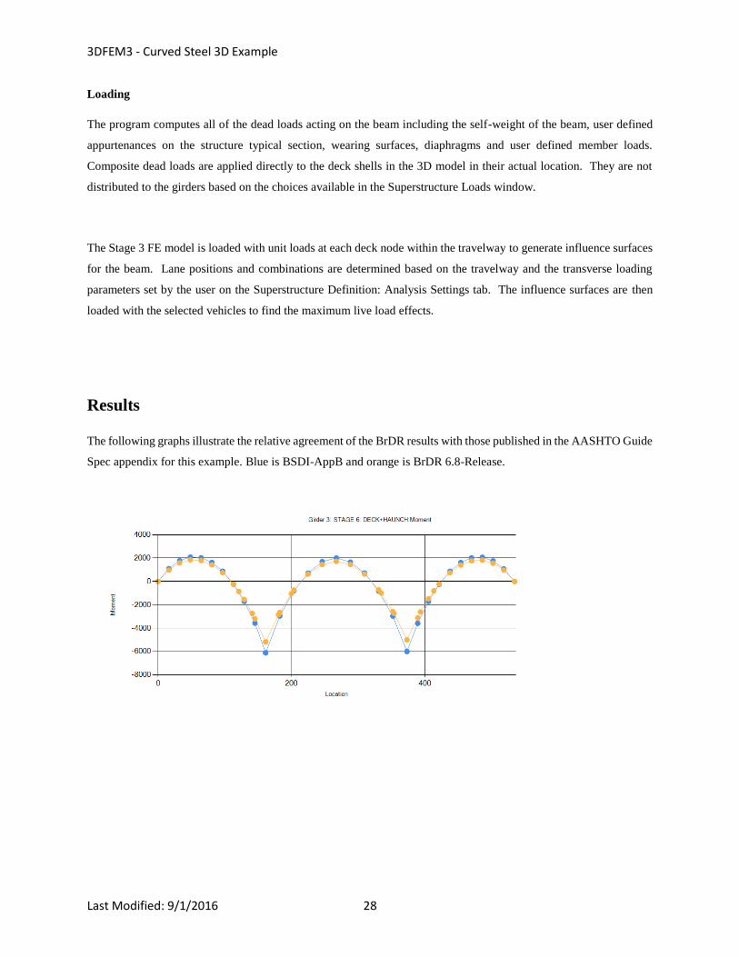
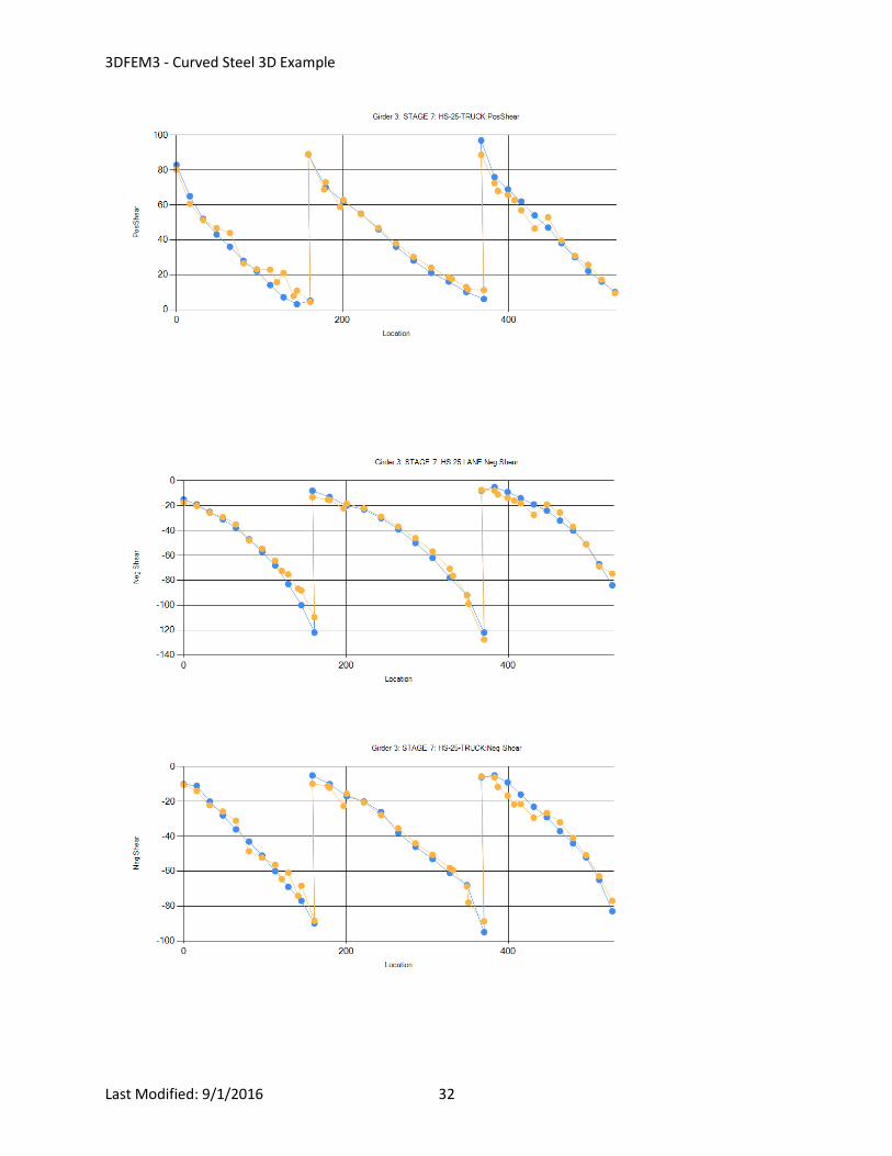
Results
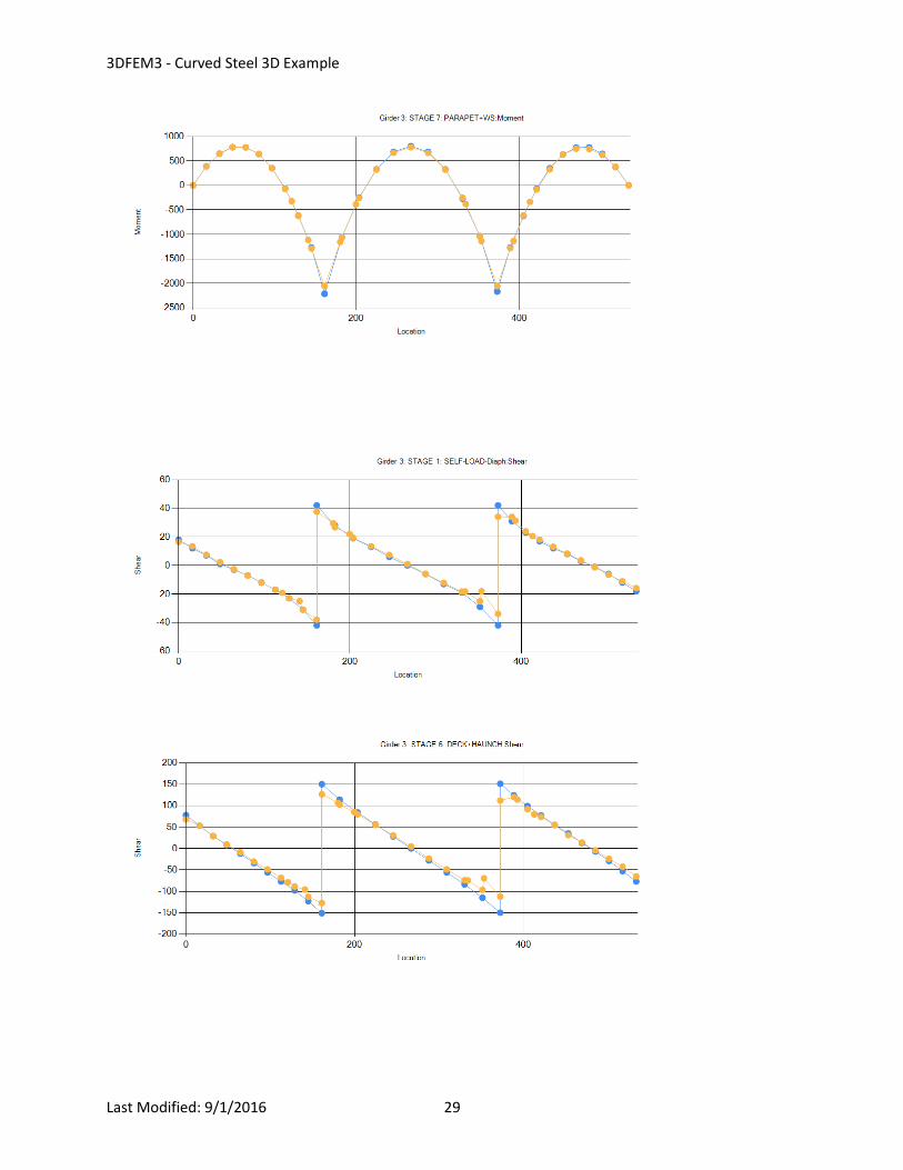
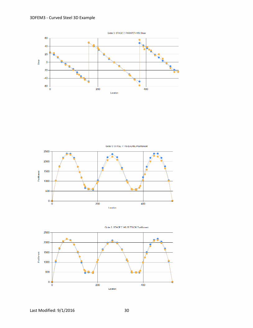
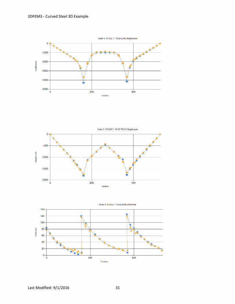
The following graphs illustrate the relative agreement of the BrDR results with those published in the AASHTO Guide
Spec appendix for this example. Blue is BSDI-AppB and orange is BrDR 6.8-Release.
3DFEM3 - Curved Steel 3D Example
Last Modified: 9/1/2016 29
3DFEM3 - Curved Steel 3D Example
Last Modified: 9/1/2016 30
3DFEM3 - Curved Steel 3D Example
Last Modified: 9/1/2016 31
3DFEM3 - Curved Steel 3D Example
Last Modified: 9/1/2016 32