Curtiss JN 4D ʺJennyʺ 41.25ʺ - AerodromeRC
8
Curtiss JN‐4D ʺJennyʺ 41.25ʺ Copyright© 2005‐11 M.K. Bengtson All Rights Reserved Rev 07/11 Curtiss JN‐4D ʺJennyʺ 41.25ʺ R/C Scale Model Instructions CONTACT INFORMATION Designed by: M.K. Bengtson Prototype by: Bert Ayers Manufactured and Distributed by: Bengtson Company e‐mail: [email protected] Web Site: www.aerodromerc.com
Transcript of Curtiss JN 4D ʺJennyʺ 41.25ʺ - AerodromeRC

Curtiss JN‐4D ʺJennyʺ 41.25ʺ
Copyright© 2005‐11 M.K. Bengtson All Rights Reserved Rev 07/11
Curtiss JN‐4D ʺJennyʺ 41.25ʺ
R/C Scale Model Instructions
CONTACT INFORMATION Designed by: M.K. Bengtson Prototype by: Bert Ayers
Manufactured and Distributed by:
Bengtson Company
e‐mail: [email protected] Web Site: www.aerodromerc.com

Curtiss JN‐4D ʺJennyʺ 41.25ʺ Page 2
Copyright© 2005‐11 M.K. Bengtson All Rights Reserved Rev 07/11
Curtiss JN 4D “Jenny” Thank you for purchasing the Curtiss Jenny model for electric flight. THE MODEL A semi scale adaptation of the Curtiss Jenny, this model is designed to be easy to build and exciting to fly.
Finished Model By Bert Ayers
POWER SET UP The model can be set up to be powered by the 6V S400 motor and the Mini‐Olympus 2.33:1 Gearbox with a 8x4 APC prop. Battery power pack can be 8 600mah NiCad or equivalent Nimh or Li‐poly. This model is using 6 600mah. R/C GEAR A four function mini receiver and four micro servos are all that is required. Aileron servos can be no thicker than 9mm to fit into aileron servo bay.
SPECIFICATIONS More than 190 laser cut parts
Scale: ~1/9 Channels: R/E/A/T Wingspan: 41.25ʺ Wing Area: 330 sq in Weight: 26 oz ready to fly (Model shown above) Power System: Speed 400, Mini‐ Olympus geared, 6V Prop: 8x4 APC Airfoil Type: Flat bottomed Cowl: N/A Spinner: N/A Wheels: balsa & plywood, Neoprene foam tires Covering: Balsa and Litespan or Polyspan Decals: Available on website Prototype By: Bert Ayers
BUILDING THE MODEL Use the plastic bag that the kit comes in to cover the plans in each of the building steps. Slit the bag down the side and sealed end to open it up into one large sheet. Laser cut parts can best be taken out of the balsa sheets by using a#11 x‐acto blade to cut the minute bridges in the laser cuts. Pushing them out without cutting the bridges may break the part. The model above was built with 1/8” square strips cut from the excess areas of the 1/8” laser sheets. CA glue for the balsa parts and epoxy for the lite‐plywood parts were used on the pictured model. TAIL SURFACES The tail surfaces are a good place to start – to get acquainted with building with laser cut parts. Find all the “S” parts on the 1/8” laser sheets, cut the small bridges where the laser didn’t cut and finish cutting the part. The part should pick out of the sheet with no effort. All the “S” parts make up the vertical stabilizer and rudder parts. Some 1/8” square stock will be needed to make the ribs. Cover the plans with the shipping bag and pin down the parts. CA glue together. Allow to set for 5 minutes and remove from the plans.
Tail Surface Construction Detail
You can sand and round all surfaces (except for S1) or leave the sanding until you get everything built. Find all the “E” parts and repeat the process to build the elevator. A 1/8” dowel or aluminum tube will be needed to join the elevators.
Curtiss JN‐4D ʺJennyʺ 41.25ʺ Page 3
Copyright© 2005‐11 M.K. Bengtson All Rights Reserved Rev 07/11
Tail Surface Construction Detail
Now that you are an expert at building with laser cut parts, we can proceed with more complicated structure. WINGS The wings require a little prep work before assembly can begin. The 1/8” x 3/8” bass spars and 1/8” square spars as well as 1/4” square balsa Leading Edge and 1/8” x 1/2” balsa Trailing Edge stock are not supplied in the kit. One top wing spar and one bottom wing spar can be cut from one 36” piece. Cut all spars to correct length. The UTE laser cut piece can be glued to the bottom 1/8” square top wing spar. Cut out the L1 ribs and glue in the 1/8” locating dowels. Cut out the L4 , R4 and R7 ribs and glue on the side pieces that reinforce the strut joints. Mark and cut the rib notches in the trailing edges.
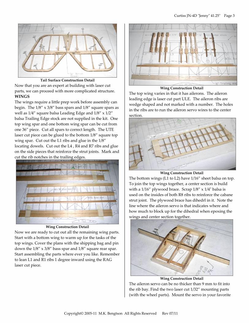
Wing Construction Detail
Now we are ready to cut out all the remaining wing parts. Start with a bottom wing to warm up for the tasks of the top wings. Cover the plans with the shipping bag and pin down the 1/8” x 3/8” bass spar and 1/8” square rear spar. Start assembling the parts where ever you like. Remember to lean L1 and R1 ribs 1 degree inward using the RAG laser cut piece.
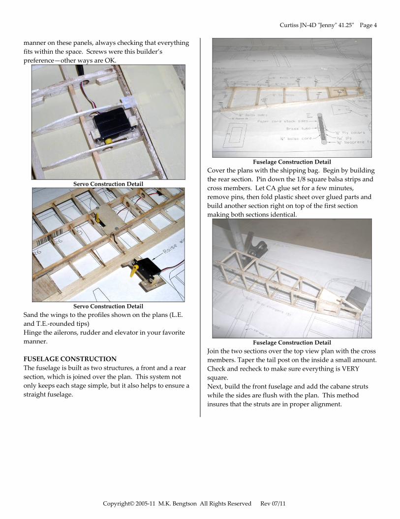
Wing Construction Detail
The top wing varies in that it has ailerons. The aileron leading edge is laser cut part ULE. The aileron ribs are wedge shaped and not marked with a number. The holes in the ribs are to run the aileron servo wires to the center section.
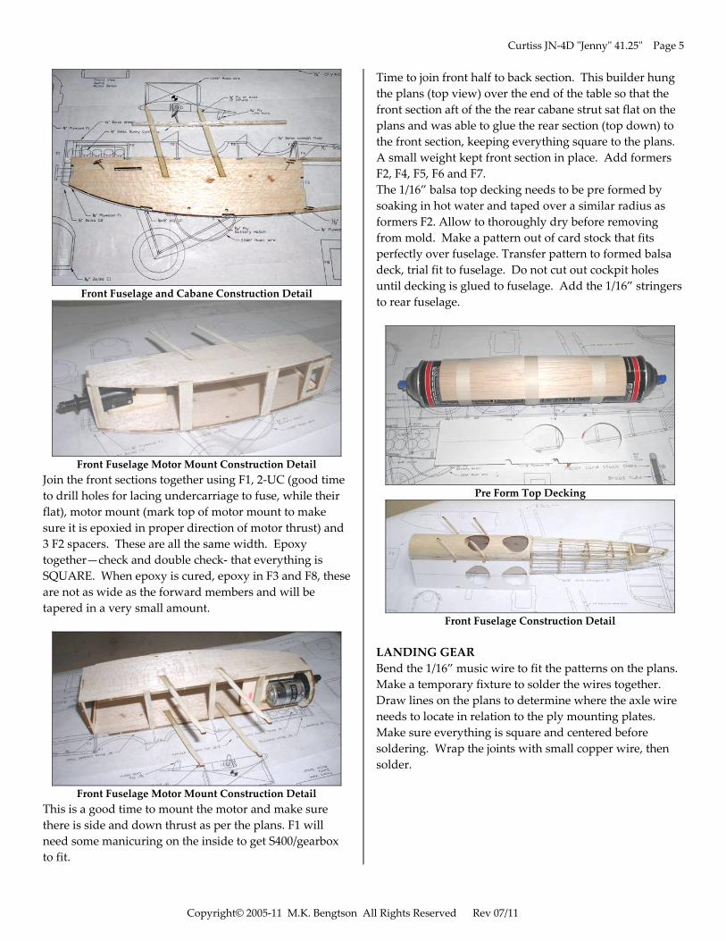
Wing Construction Detail
The bottom wings (L1 to L2) have 1/16” sheet balsa on top. To join the top wings together, a center section is build with a 1/16” plywood brace. Scrap 1/8” x 1/4ʺ balsa is used on the insides of both R8 ribs to reinforce the cabane strut joint. The plywood brace has dihedrl in it. Note the line where the aileron servo is that indicates where and how much to block up for the dihedral when epoxing the wings and center section together.
Wing Construction Detail
The aileron servo can be no thicker than 9 mm to fit into the rib bay. Find the two laser cut 1/32” mounting parts (with the wheel parts). Mount the servo in your favorite
Curtiss JN‐4D ʺJennyʺ 41.25ʺ Page 4
Copyright© 2005‐11 M.K. Bengtson All Rights Reserved Rev 07/11
manner on these panels, always checking that everything fits within the space. Screws were this builder’s preference—other ways are OK.
Servo Construction Detail
Servo Construction Detail
Sand the wings to the profiles shown on the plans (L.E. and T.E.‐rounded tips) Hinge the ailerons, rudder and elevator in your favorite manner. FUSELAGE CONSTRUCTION The fuselage is built as two structures, a front and a rear section, which is joined over the plan. This system not only keeps each stage simple, but it also helps to ensure a straight fuselage.
Fuselage Construction Detail
Cover the plans with the shipping bag. Begin by building the rear section. Pin down the 1/8 square balsa strips and cross members. Let CA glue set for a few minutes, remove pins, then fold plastic sheet over glued parts and build another section right on top of the first section making both sections identical.
Fuselage Construction Detail
Join the two sections over the top view plan with the cross members. Taper the tail post on the inside a small amount. Check and recheck to make sure everything is VERY square. Next, build the front fuselage and add the cabane struts while the sides are flush with the plan. This method insures that the struts are in proper alignment.
Curtiss JN‐4D ʺJennyʺ 41.25ʺ Page 5
Copyright© 2005‐11 M.K. Bengtson All Rights Reserved Rev 07/11
Front Fuselage and Cabane Construction Detail
Front Fuselage Motor Mount Construction Detail
Join the front sections together using F1, 2‐UC (good time to drill holes for lacing undercarriage to fuse, while their flat), motor mount (mark top of motor mount to make sure it is epoxied in proper direction of motor thrust) and 3 F2 spacers. These are all the same width. Epoxy together—check and double check‐ that everything is SQUARE. When epoxy is cured, epoxy in F3 and F8, these are not as wide as the forward members and will be tapered in a very small amount.
Front Fuselage Motor Mount Construction Detail
This is a good time to mount the motor and make sure there is side and down thrust as per the plans. F1 will need some manicuring on the inside to get S400/gearbox to fit.
Time to join front half to back section. This builder hung the plans (top view) over the end of the table so that the front section aft of the the rear cabane strut sat flat on the plans and was able to glue the rear section (top down) to the front section, keeping everything square to the plans. A small weight kept front section in place. Add formers F2, F4, F5, F6 and F7. The 1/16” balsa top decking needs to be pre formed by soaking in hot water and taped over a similar radius as formers F2. Allow to thoroughly dry before removing from mold. Make a pattern out of card stock that fits perfectly over fuselage. Transfer pattern to formed balsa deck, trial fit to fuselage. Do not cut out cockpit holes until decking is glued to fuselage. Add the 1/16” stringers to rear fuselage.
Pre Form Top Decking
Front Fuselage Construction Detail
LANDING GEAR Bend the 1/16” music wire to fit the patterns on the plans. Make a temporary fixture to solder the wires together. Draw lines on the plans to determine where the axle wire needs to locate in relation to the ply mounting plates. Make sure everything is square and centered before soldering. Wrap the joints with small copper wire, then solder.
Curtiss JN‐4D ʺJennyʺ 41.25ʺ Page 6
Copyright© 2005‐11 M.K. Bengtson All Rights Reserved Rev 07/11
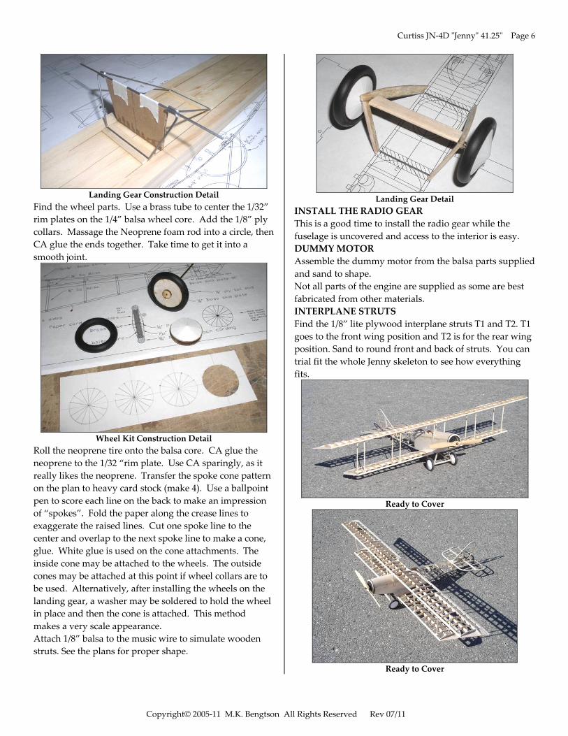
Landing Gear Construction Detail
Find the wheel parts. Use a brass tube to center the 1/32” rim plates on the 1/4” balsa wheel core. Add the 1/8” ply collars. Massage the Neoprene foam rod into a circle, then CA glue the ends together. Take time to get it into a smooth joint.
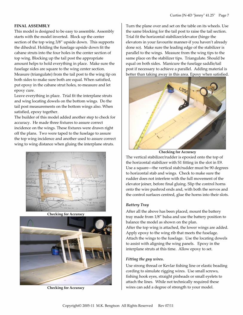
Wheel Kit Construction Detail
Roll the neoprene tire onto the balsa core. CA glue the neoprene to the 1/32 “rim plate. Use CA sparingly, as it really likes the neoprene. Transfer the spoke cone pattern on the plan to heavy card stock (make 4). Use a ballpoint pen to score each line on the back to make an impression of “spokes”. Fold the paper along the crease lines to exaggerate the raised lines. Cut one spoke line to the center and overlap to the next spoke line to make a cone, glue. White glue is used on the cone attachments. The inside cone may be attached to the wheels. The outside cones may be attached at this point if wheel collars are to be used. Alternatively, after installing the wheels on the landing gear, a washer may be soldered to hold the wheel in place and then the cone is attached. This method makes a very scale appearance. Attach 1/8” balsa to the music wire to simulate wooden struts. See the plans for proper shape.
Landing Gear Detail
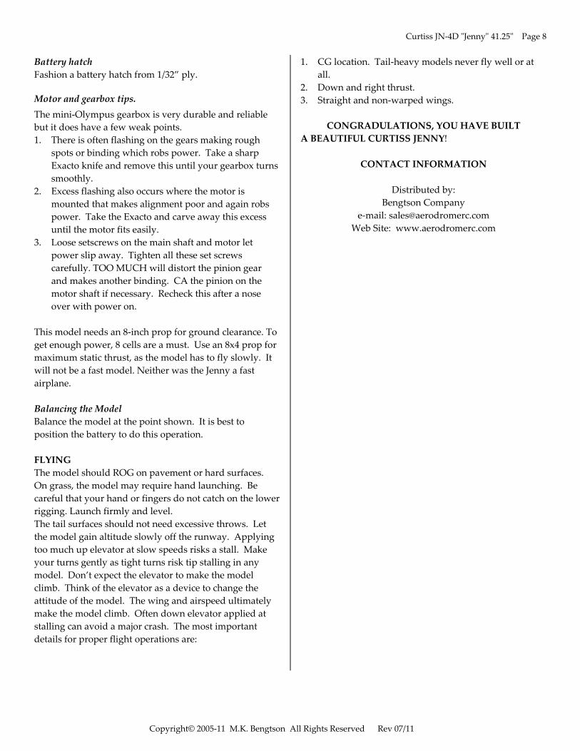
INSTALL THE RADIO GEAR This is a good time to install the radio gear while the fuselage is uncovered and access to the interior is easy. DUMMY MOTOR Assemble the dummy motor from the balsa parts supplied and sand to shape. Not all parts of the engine are supplied as some are best fabricated from other materials. INTERPLANE STRUTS Find the 1/8” lite plywood interplane struts T1 and T2. T1 goes to the front wing position and T2 is for the rear wing position. Sand to round front and back of struts. You can trial fit the whole Jenny skeleton to see how everything fits.
Ready to Cover
Ready to Cover
Curtiss JN‐4D ʺJennyʺ 41.25ʺ Page 7
Copyright© 2005‐11 M.K. Bengtson All Rights Reserved Rev 07/11
FINAL ASSEMBLY This model is designed to be easy to assemble. Assembly starts with the model inverted. Block up the center section of the top wing 3/8” upside down. This supports the dihedral. Holding the fuselage upside down fit the cabane struts into the four holes in the center section of top wing. Blocking up the tail post the appropriate amount helps to hold everything in place. Make sure the fuselage sides are square to the wing center section. Measure (triangulate) from the tail post to the wing tip on both sides to make sure both are equal. When satisfied, put epoxy in the cabane strut holes, re‐measure and let epoxy cure. Leave everything in place. Trial fit the interplane struts and wing locating dowels on the bottom wings. Do the tail post measurements on the bottom wings also. When satisfied, epoxy together. The builder of this model added another step to check for accuracy. He made three fixtures to assure correct incidence on the wings. These fixtures were drawn right off the plans. Two were taped to the fuselage to assure the top wing incidence and another used to assure correct wing to wing distance when gluing the interplane struts.
Checking for Accuracy
Checking for Accuracy
Turn the plane over and set on the table on its wheels. Use the same blocking for the tail post to raise the tail section. Trial fit the horizontal stabilizer/elevator (hinge the elevators in your favourite manner‐if you haven’t already done so). Make sure the leading edge of the stabilizer is parallel to the wings. Measure from the wing tips to the same place on the stabilizer tips. Triangulate. Should be equal on both sides. Manicure the fuselage saddle/tail post if necessary to achieve a parallel. Adding material is better than taking away in this area. Epoxy when satisfied.
Checking for Accuracy
The vertical stabilizer/rudder is epoxied onto the top of the horizontal stabilizer with S1 fitting in the slot in E9. Use a square‐‐‐the vertical stab/rudder must be 90 degrees to horizontal stab and wings. Check to make sure the rudder does not interfere with the full movement of the elevator joiner, before final gluing. Slip the control horns onto the wire pushrod ends and, with both the servos and the control surfaces centred, glue the horns into their slots.
Battery Tray After all the above has been placed, mount the battery tray made from 1/8” balsa and use the battery position to balance the model as shown on the plan. After the top wing is attached, the lower wings are added. Apply epoxy to the wing rib that meets the fuselage. Attach the wings to the fuselage. Use the locating dowels to assist with aligning the wing panels. Epoxy in the interplane struts at this time. Allow epoxy to set.
Fitting the guy wires. Use strong thread or Kevlar fishing line or elastic beading cording to simulate rigging wires. Use small screws, fishing hook eyes, straight pinheads or small eyelets to attach the lines. While not technically required these wires can add a degree of strength to your model.
Curtiss JN‐4D ʺJennyʺ 41.25ʺ Page 8
Copyright© 2005‐11 M.K. Bengtson All Rights Reserved Rev 07/11
Battery hatch Fashion a battery hatch from 1/32” ply.
Motor and gearbox tips. The mini‐Olympus gearbox is very durable and reliable but it does have a few weak points. 1. There is often flashing on the gears making rough
spots or binding which robs power. Take a sharp Exacto knife and remove this until your gearbox turns smoothly.
2. Excess flashing also occurs where the motor is mounted that makes alignment poor and again robs power. Take the Exacto and carve away this excess until the motor fits easily.
3. Loose setscrews on the main shaft and motor let power slip away. Tighten all these set screws carefully. TOO MUCH will distort the pinion gear and makes another binding. CA the pinion on the motor shaft if necessary. Recheck this after a nose over with power on.
This model needs an 8‐inch prop for ground clearance. To get enough power, 8 cells are a must. Use an 8x4 prop for maximum static thrust, as the model has to fly slowly. It will not be a fast model. Neither was the Jenny a fast airplane. Balancing the Model Balance the model at the point shown. It is best to position the battery to do this operation. FLYING The model should ROG on pavement or hard surfaces. On grass, the model may require hand launching. Be careful that your hand or fingers do not catch on the lower rigging. Launch firmly and level. The tail surfaces should not need excessive throws. Let the model gain altitude slowly off the runway. Applying too much up elevator at slow speeds risks a stall. Make your turns gently as tight turns risk tip stalling in any model. Don’t expect the elevator to make the model climb. Think of the elevator as a device to change the attitude of the model. The wing and airspeed ultimately make the model climb. Often down elevator applied at stalling can avoid a major crash. The most important details for proper flight operations are:
1. CG location. Tail‐heavy models never fly well or at all.
2. Down and right thrust. 3. Straight and non‐warped wings.
CONGRADULATIONS, YOU HAVE BUILT A BEAUTIFUL CURTISS JENNY!
CONTACT INFORMATION
Distributed by: Bengtson Company
e‐mail: [email protected] Web Site: www.aerodromerc.com