Gaining a Sense of Touch. Physical Parameters Estimation ...
Abstract—Virtual touch screen using camera is an ordinary screen which uses a camera to imitate the touch screen by taking a picture of an indicator, e.g., finger, which is laid on the screen, converting the indicator tip position on the picture to the position on the screen, and moving the cursor on the screen to that position. In fact, the indicator is not laid on the screen directly, but it is intervened by the cover at some intervals. In spite of this gap, if the eye-indicator-camera angle is not large, the mapping from the indicator tip positions on the image to the corresponding cursor positions on the screen is not difficult and could be done with a little error. However, the larger the angle is, the bigger the error in the mapping occurs. This paper proposes cursor position estimation model for virtual touch screen using camera which could eliminate this kind of error. The proposed model (i) moves the on-screen pilot cursor to the screen position which locates on the screen at the position just behind the indicator tip when the indicator tip has been looked from the camera position, and then (ii) converts that pilot cursor position to the desirable cursor position (the position on the screen when it has been looked from the user’s eye through the indicator tip) by using the bilinear transformation. Simulation results show the correctness of the estimated cursor position by using the proposed model.
Keywords— bilinear transformation, cursor position, pilot cursor, virtual touch screen
I. INTRODUCTION IRTUAL touch screen using camera is an alternative device for the real touch screen. The user of this kind of
system is capable of transforming an ordinary screen into a touch screen using an ordinary camera. The system proposed in [1] is an example of this kind of system. To establish the system, the mapping from the indicator tip position on the image to the cursor position on the screen must be performed. Cursor position estimation model for virtual touch screen using camera is proposed in this paper for this image-screen mapping. The proposed model is capable of efficacious and correct mapping even though the gap between the screen and the screen cover, and the angle between the camera, the indicator tip, and the user’s eye is large.
Manuscript received March 30, 2005. S. Wangsiripitak is with the Computer Engineering Department, Faculty of
Engineering, King Mongkut’s Institute of Technology Ladkrabang, Bangkok 10520 Thailand (phone: (+66) 2-739-2400, fax: (+66) 2-739-2404, e-mail: [email protected]).
II. PROBLEMS IN SOME PREVIOUS METHODS Several image-screen mapping algorithms are proposed in
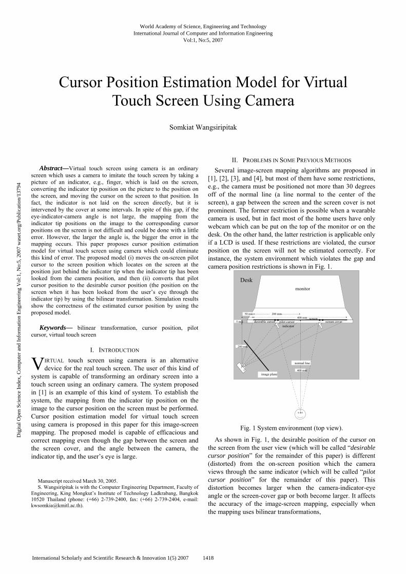
[1], [2], [3], and [4], but most of them have some restrictions, e.g., the camera must be positioned not more than 30 degrees off of the normal line (a line normal to the center of the screen), a gap between the screen and the screen cover is not prominent. The former restriction is possible when a wearable camera is used, but in fact most of the home users have only webcam which can be put on the top of the monitor or on the desk. On the other hand, the latter restriction is applicable only if a LCD is used. If these restrictions are violated, the cursor position on the screen will not be estimated correctly. For instance, the system environment which violates the gap and camera position restrictions is shown in Fig. 1.
screen screen cover pilot cursor desirable cursor
indicator
monitor
normal line
400 mm
200 mm
50 mm 200 mm
Desk
5 mm
400 mm image plane
Fig. 1 System environment (top view).
As shown in Fig. 1, the desirable position of the cursor on the screen from the user view (which will be called “desirable cursor position” for the remainder of this paper) is different (distorted) from the on-screen position which the camera views through the same indicator (which will be called “pilot cursor position” for the remainder of this paper). This distortion becomes larger when the camera-indicator-eye angle or the screen-cover gap or both become larger. It affects the accuracy of the image-screen mapping, especially when the mapping uses bilinear transformations,
Cursor Position Estimation Model for Virtual Touch Screen Using Camera
Somkiat Wangsiripitak
V
World Academy of Science, Engineering and TechnologyInternational Journal of Computer and Information Engineering
Vol:1, No:5, 2007
1418International Scholarly and Scientific Research & Innovation 1(5) 2007
Dig
ital O
pen
Scie
nce
Inde
x, C
ompu
ter
and
Info
rmat
ion
Eng
inee
ring
Vol
:1, N
o:5,
200
7 w
aset
.org
/Pub
licat
ion/
1379
4
,3210
3210
xybybxbbyxyayaxaax
+++=′+++=′ (1)
to convert the tip position on the image into the desirable cursor position on the screen, because this distortion could not be taken into consideration well enough. As the result, the error would occur in the estimated cursor position.
To show the above-mentioned error, the virtual touch screen using camera shown in Fig. 1 is set up in the simulation. The eye and the pin-hole camera are located at the same height as the height of the screen center. The focal length of the camera is 6.2 mm.
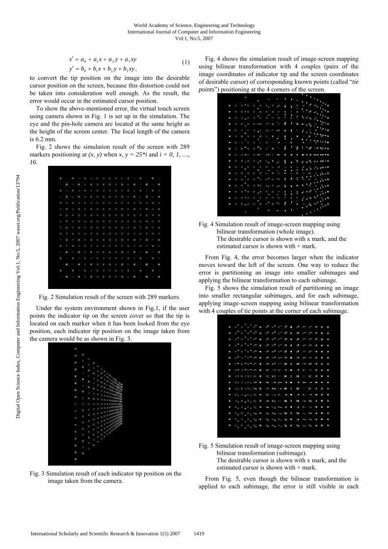
Fig. 2 shows the simulation result of the screen with 289 markers positioning at (x, y) when x, y = 25*i and i = 0, 1, …, 16.
Fig. 2 Simulation result of the screen with 289 markers.
Under the system environment shown in Fig.1, if the user points the indicator tip on the screen cover so that the tip is located on each marker when it has been looked from the eye position, each indicator tip position on the image taken from the camera would be as shown in Fig. 3.
Fig. 3 Simulation result of each indicator tip position on the
image taken from the camera.
Fig. 4 shows the simulation result of image-screen mapping using bilinear transformation with 4 couples (pairs of the image coordinates of indicator tip and the screen coordinates of desirable cursor) of corresponding known points (called “tie points”) positioning at the 4 corners of the screen.
Fig. 4 Simulation result of image-screen mapping using
bilinear transformation (whole image). The desirable cursor is shown with x mark, and the estimated cursor is shown with + mark.
From Fig. 4, the error becomes larger when the indicator moves toward the left of the screen. One way to reduce the error is partitioning an image into smaller subimages and applying the bilinear transformation to each subimage.
Fig. 5 shows the simulation result of partitioning an image into smaller rectangular subimages, and for each subimage, applying image-screen mapping using bilinear transformation with 4 couples of tie points at the corner of each subimage.
Fig. 5 Simulation result of image-screen mapping using
bilinear transformation (subimage). The desirable cursor is shown with x mark, and the estimated cursor is shown with + mark.
From Fig. 5, even though the bilinear transformation is applied to each subimage, the error is still visible in each
World Academy of Science, Engineering and TechnologyInternational Journal of Computer and Information Engineering
Vol:1, No:5, 2007
1419International Scholarly and Scientific Research & Innovation 1(5) 2007
Dig
ital O
pen
Scie
nce
Inde
x, C
ompu
ter
and
Info
rmat
ion
Eng
inee
ring
Vol
:1, N
o:5,
200
7 w
aset
.org
/Pub
licat
ion/
1379
4

subimage. The reason is that the degrees of polynomial equations in the bilinear transformations are not high enough to imitate the distortion occurring during image-screen mapping. In theory, if the higher degree of polynomial equation is applied to image-screen mapping, the error would become smaller. But increasing the degree of polynomial equation requires more known tie points. For example, if
228
27
26
25
243210
228
27
26
25
243210
yxbxybyxbybxbxybybxbby
yxaxyayxayaxaxyayaxaax
++++++++=′
++++++++=′ (2)
are used in the image-screen mapping, the user must provide 8 couples of corresponding known points. This could be done by asking the user to point the indicator tip at 8 on-screen markers, taking a picture for each time, and then keep the positions of each pair of coordinates, i.e., image coordinates of the tip and screen coordinates of the marker. If the system requires more accuracy, then higher degree of polynomial equation must be employed, such as the following general polynomial equation:
.0 0
0 0
∑ ∑
∑ ∑
=
−
=
=
−
=
=′
=′
m
r
rm
k
krrk
m
r
rm
k
krrk
yxby
yxax (3)
This means that the user must help the system to locate more couples of tie points. As the result, the user might feel inconvenient.
In the next section, more efficacious and error-free mapping algorithm is proposed to solve these problems.
III. THE PROPOSED MODEL Cursor position estimation model for virtual touch screen
using camera is proposed in this paper. The proposed model allow the camera to be positioned anywhere that the whole screen can be captured into an image, i.e., the camera could be positioned more than 30 degrees off of the normal line. This means that the home users need not to use the wearable camera, but they just put their ordinary webcam anywhere on the desk where the whole screen could be captured. Furthermore the gap between the screen and the screen cover could be any length, i.e., the screen could be an LCD or an ordinary monitor. The proposed model is capable of eliminating the distortion error in a previous image-screen mapping method. The proposed algorithm is described as follows.
A. Configuration for pilot cursor to desirable cursor mapping
For the first time of use, user must provide 4 couples of pilot cursor positions and desirable cursor positions. The pilot cursor is the cursor positioning on the screen just behind the indicator tip when they are viewed from the camera. The desirable cursor is the cursor positioning on the screen just behind the indicator tip when they are viewed from the user’s eye. These 4 couples of coordinates will be used later to map the other pilot cursor positions to the desirable cursor positions during the use of virtual touch screen system. The detailed algorithm is described as follows.
Step A1: Display the desirable cursor on the screen. Step A2: Put the indicator on the screen cover so that the
indicator tip is just over the desirable cursor when they are viewed from the user’s eye.
Step A3: Move the pilot cursor on the screen toward the position of the indicator tip until the pilot cursor is just behind the indicator tip when they are viewed from the camera (i.e., until the image coordinates of the pilot cursor equal to the image coordinates of the indicator’s tip).
Step A4: Keep the positions of the pilot cursor and the corresponding desirable cursor.
Step A5: Display the next desirable cursor on the screen, and repeat step A2 – A4 until 4 couples of pilot cursors and desirable cursors are established.
Step A6: Use these 4 couples of coordinates and (1) to calculate the coefficients a0 – a3 and b0 – b3.
Step A7: Use the coefficients a0 – a3 and b0 – b3 from step A6 to establish the bilinear transformations which will be used in the next subsection.
B. Image-screen mapping using pilot cursor To prevent the distortion from using the bilinear
transformations in image-screen mapping during the execution of the virtual touch screen using camera, the pilot cursor created by the system is used instead to find the on-screen position which is just behind the indicator tip when they are viewed from the camera. This pilot cursor position will be used later to find the desirable cursor position. The detailed algorithm when user moves the indicator to the next position is described as follows. Step B1: Segment the indicator from the image background. Step B2: Find the tip position of the indicator on the current
frame and compare it with the pilot cursor position on the last detectable frame. Determine the next moving direction by setting it to the vector from the pilot cursor position to the tip position.
Step B3: Move the pilot cursor on the screen toward the position of the indicator by some distance value. Keep its screen coordinates.
Step B4: Convert the screen coordinates of the pilot cursor to the screen coordinates of the desirable cursor by using bilinear transformations established in step A7.
Step B5: Segment the pilot cursor from the image background and keep its image coordinates.
Step B6: Repeat step B1 – B5 until, in the image, the pilot cursor locates at the same position as the indicator tip (i.e., when the pilot cursor is viewed from the camera, it locates just behind the indicator tip).
As described above, the mapping from the image coordinates of an indicator tip to the screen coordinates of a pilot cursor in step B1 – B3 and B5 – B6 is done by the help of the computer interactions, not by the bilinear transformations, thus it is guaranteed that there is no distortion occured.
In addition, the conversion from the pilot cursor position to the desirable cursor position in step B4 is done between two
World Academy of Science, Engineering and TechnologyInternational Journal of Computer and Information Engineering
Vol:1, No:5, 2007
1420International Scholarly and Scientific Research & Innovation 1(5) 2007
Dig
ital O
pen
Scie
nce
Inde
x, C
ompu
ter
and
Info
rmat
ion
Eng
inee
ring
Vol
:1, N
o:5,
200
7 w
aset
.org
/Pub
licat
ion/
1379
4

positions on the screen, so the normal bilinear transformation is adequate to be applied without any distortion.
IV. SIMULATION RESULTS The system environment used in the simulations is shown in
Fig. 1. In the simulations, the screen is of size 400 mm × 400 mm, the interval between the screen and the screen cover is 5 mm, the user’s eye locates at 400 mm away from the center of the screen cover and along the screen normal line, and the camera’s pin hole locates at the same height as the eye, 200 mm in front of the screen cover, and 250 mm left of the screen normal line. The focal length of the camera is 6.2 mm.
In the simulations, the test pattern with 289 desirable cursor positions in Fig. 2 is used.
Fig. 6 Simulation result of pilot cursor positions (+ mark)
comparing to desirable cursor positions (x mark).
Fig. 7 Simulation result of estimated cursor positions (+ mark)
comparing to desirable cursor positions (x mark).
Fig. 6 shows the simulation result of pilot cursor positions (+ mark) when the aforementioned algorithm is applied. The desirable cursor positions (x mark) are also displayed for comparison.
Fig. 7 shows the simulation result of estimated cursor positions (+ mark) when the algorithm in step B4 is applied. The desirable cursor positions (x mark) are also displayed for comparison.
From Fig. 7, the estimated cursors locate exactly the same position as the desirable cursors. This means that if the pilot cursor position on the screen could be determined correctly by using the computer interaction described above, the desirable cursor position would be estimated correctly.
V. CONCLUSION Cursor position estimation model for virtual touch screen
using camera is proposed in this paper. The simulations show the efficiency and correctness of the proposed model. In the real world, there are still some issues to be solved, e.g., how far the moved distance value of the pilot cursor and which direction should be in step B3, what kind of the pilot cursor should be used to prevent the occlusion when the indicator moves over the pilot cursor, which condition should be used in step B6 to test whether the image coordinates of the pilot cursor are at the same position as the image coordinates of the indicator tip.
For the first issue, the moved distance of the pilot cursor could be set depending on the need of the user. If the user wants to simulate the rapid movement of the cursor, the value should be large; if not, the value should be small. In addition, the moved distance in the right area of the screen should be larger than the moved distance in the left area. If the camera is set as shown in Fig. 1, the pilot cursor could move in the screen in the same direction as the next moving direction determined in step B2.
For the second issue, the horizontal line which is longer than the horizontal length of the indicator could be used to prevent the occlusion.
For the third issue, if the horizontal line is used as the pilot cursor, it is easy to test whether the condition is true or false by testing the equality of the row position of the horizontal line and that of the indicator, and testing the equality of the column position of the horizontal line’s midpoint and that of the indicator.
REFERENCES [1] Z. Zhang, “Vision-based Interaction with Fingers and Papers,” Proc.
International Symposium on the CREST Digital Archiving Project, pp. 83-106, May. 2003.
[2] J. Coutaz, Crowley, J. L., and F. B rard., “Things that see: Machine perception for human computer interaction,” Communications of the ACM, 43(3):54-64, 2000.
[3] C. Maggioni and B. Kammerer, “Gesture computer – history, design and applications, in Ed. R. Cipolla and A. Pentland, editors,” Computer Vision for Human-Machine Interaction, Cambridge University Press, 1998.
[4] T. Starner, S. Mann, B. Rhodes, J. Levine, J. Healey, D. Kirsch, R. W. Picard, and A. Pentland, “Augmented reality through wearable computing,” Presence, Special Issue on Augmented Reality, 6(4), 1997.
World Academy of Science, Engineering and TechnologyInternational Journal of Computer and Information Engineering
Vol:1, No:5, 2007
1421International Scholarly and Scientific Research & Innovation 1(5) 2007
Dig
ital O
pen
Scie
nce
Inde
x, C
ompu
ter
and
Info
rmat
ion
Eng
inee
ring
Vol
:1, N
o:5,
200
7 w
aset
.org
/Pub
licat
ion/
1379
4


![Cursor Control with Webcam-Based Head Pose Estimation€¦ · the gazr library created by Lemaignan et al. [10], which implements 3D head pose estimation using the dlib face de-tector](https://static.fdocuments.net/doc/165x107/5ecc42eee2e77955c85a55ab/cursor-control-with-webcam-based-head-pose-estimation-the-gazr-library-created-by.jpg)