Current Status and Prospects of Supercomputing Used · PDF fileCurrent Status and Prospects of...
11
Journal of Energy and Power Engineering 10 (2016) 82-92 doi: 10.17265/1934-8975/2016.02.002 Current Status and Prospects of Supercomputing Used for Gas Turbine Engines Design Omair Alhatim National Center for Jet Engine Technology, King Abdul-Aziz City for Science and Technology, Riyadh 11442, Saudi Arabia Received: December 21, 2015 / Accepted: January 06, 2016 / Published: February 29, 2016. Abstract: The engineering analysis techniques used for the GTE (gas turbine engines) design are presented, the physical effects, which impact is not currently taken into account are described, further research directions to strengthen core design competencies are identified, the requirements for computing power are formulated. Internal cooling techniques for gas turbine blades have been studied for several decades. The internal cooling techniques of the gas turbine blade includes: jet impingement, rib turbulated cooling, and pin-fin cooling which have been developed to maintain the metal temperature of turbine vane and blades within acceptable limits in this harsh environment. Key words: Engineering analysis, GTE design, aerodynamics of impeller machines, heat-and-mass transfer, blade internal cooling. 1. Introduction The engineering calculation is the primary mean to reduce the cost of new products designing in mechanical engineering, because it avoids long-term preliminary development phase [1]. Therefore, virtual engineering, which includes the research and optimization of geometrical and physical properties of the product, is the most progressive current trend in the evaluation environment [2]. Using computer simulations in a virtual environment is a mandatory component of the core competence of the company, working in high-tech engineering market, such as gas turbine engines. Core competencies, by definition [3], are the complex interaction of specific individual technologies and skills, that should provide potential access to different markets, determine the specific advantages of the company’s final product and should be virtually non-reproducible by competitors. The core competence of turbine engine manufacturing is the design of the gas generator (high-pressure loop). The fact of possession of this competence determined by Corresponding author: Omair Alhatim, Dr., research assistant professor, research field: jet propulsion. three factors: design of modern high efficiency heavy loaded impeller machines; design of turbine cooled blades; design of effective combustion chambers with low hazardous emission. 2. Aerodynamics of Impeller Machines The dominant current aerodynamic modelling approach for design of compressors and GTE (gas turbine engines) turbines is the solution of steady and unsteady RANS (Reynolds (Favre) averaged Navier-Stokes) equations. The main concept of this method involves substituting of the instantaneous values of a turbulent flow with the sum of their time-averaged values, and the deviations from the average values. This simplifies the Navier-Stokes equations, but results in the appearance of additional variables which determining requires the introduction of new equations. For example, in k-ε model, two additional equations for transport of the turbulent kinetic energy and transport of turbulence dissipation are solved. There are also other commonly used differential turbulence models: k-ω, The SST (shear D DAVID PUBLISHING
Transcript of Current Status and Prospects of Supercomputing Used · PDF fileCurrent Status and Prospects of...

Journal of Energy and Power Engineering 10 (2016) 82-92 doi: 10.17265/1934-8975/2016.02.002
Current Status and Prospects of Supercomputing Used
for Gas Turbine Engines Design
Omair Alhatim
National Center for Jet Engine Technology, King Abdul-Aziz City for Science and Technology, Riyadh 11442, Saudi Arabia
Received: December 21, 2015 / Accepted: January 06, 2016 / Published: February 29, 2016. Abstract: The engineering analysis techniques used for the GTE (gas turbine engines) design are presented, the physical effects, which impact is not currently taken into account are described, further research directions to strengthen core design competencies are identified, the requirements for computing power are formulated. Internal cooling techniques for gas turbine blades have been studied for several decades. The internal cooling techniques of the gas turbine blade includes: jet impingement, rib turbulated cooling, and pin-fin cooling which have been developed to maintain the metal temperature of turbine vane and blades within acceptable limits in this harsh environment. Key words: Engineering analysis, GTE design, aerodynamics of impeller machines, heat-and-mass transfer, blade internal cooling.
1. Introduction
The engineering calculation is the primary mean to
reduce the cost of new products designing in
mechanical engineering, because it avoids long-term
preliminary development phase [1]. Therefore, virtual
engineering, which includes the research and
optimization of geometrical and physical properties of
the product, is the most progressive current trend in the
evaluation environment [2]. Using computer
simulations in a virtual environment is a mandatory
component of the core competence of the company,
working in high-tech engineering market, such as gas
turbine engines. Core competencies, by definition [3],
are the complex interaction of specific individual
technologies and skills, that should provide potential
access to different markets, determine the specific
advantages of the company’s final product and should
be virtually non-reproducible by competitors. The core
competence of turbine engine manufacturing is the
design of the gas generator (high-pressure loop). The
fact of possession of this competence determined by
Corresponding author: Omair Alhatim, Dr., research
assistant professor, research field: jet propulsion.
three factors:
design of modern high efficiency heavy loaded
impeller machines;
design of turbine cooled blades;
design of effective combustion chambers with low
hazardous emission.
2. Aerodynamics of Impeller Machines
The dominant current aerodynamic modelling
approach for design of compressors and GTE (gas
turbine engines) turbines is the solution of steady and
unsteady RANS (Reynolds (Favre) averaged
Navier-Stokes) equations. The main concept of this
method involves substituting of the instantaneous
values of a turbulent flow with the sum of their
time-averaged values, and the deviations from the
average values. This simplifies the Navier-Stokes
equations, but results in the appearance of additional
variables which determining requires the introduction
of new equations. For example, in k-ε model, two
additional equations for transport of the turbulent
kinetic energy and transport of turbulence dissipation
are solved. There are also other commonly used
differential turbulence models: k-ω, The SST (shear
D DAVID PUBLISHING

Current Status and Prospects of Supercomputing Used for Gas Turbine Engines Design
83
stress transport), Spalart and Allmaras, etc. Their main
advantages are the relative simplicity and low costs of
the calculations. To ensure the reliability of the
obtained results such models include experimental
model constants. In most cases, the RANS approach
provides a satisfactory accuracy at design computation
stage using typical personal computers. Since the grid
size for the spatial steady aerodynamics computation of
a single blade passage of the compressor or uncooled
turbine blade is approximately 300,000 units (using the
“wall-adjacent” functions in the boundary layer),
which requires a 400-450 Mb RAM (random-access
memory) unstructured for CFD (computational fluid
dynamics)―unstructured solver.
However, the above approach does not provide a
high degree reliable characterization of such physical
effects as a unsteady “stator-rotor” blading interaction
of turbo-machines (stator―the stationary blading,
rotor―the rotating blading), the flow trajectory behind
blades and detached shocks, detailed formation on the
boundary layer at the blade surface, its interaction with
the radial gap flow, separating and eddy currents, their
effect on the overall aerodynamic efficiency of the
compressor or the turbine [4]. These physical effects,
being the parameters of uncertainties during design,
force the designer to over-design the airflow for up to
5% and the COP (coefficient of performance) for up to
3%. Currently, the compressor stall margin in the entire
operating range also cannot be reliably predicted.
Finally, considering the units build errors in, the task of
meeting of all the design technical specification
requirements becomes too difficult. Fig. 1 shows a
typical flow structure in the supersonic turbo-machine
stage (compressor stage).
Fig. 2 shows the vortex flow in the inter-blade
channel of the turbomachine (turbine).
Fig. 1 Turbo-machine stage (stator-rotor-stator).
Fig. 2 Blade channel of the turbine row.

Current Status and Prospects of Supercomputing Used for Gas Turbine Engines Design
84
Fig. 3 The compressor stage aerodynamic modelling uncertainty for different approaches.
The solution of the problem of ensuring a reliable
turbo-machine aerodynamics is possible under the
following conditions:
experimental study of fundamental physical
process in turbo-machine wheelspace (boundary layers
and eddy currents, shock waves, flow trajectory behind
blades, “stator-rotor” blading interaction);
development of mathematical models and
numerical simulation methods for aerodynamics based
on the experiment.
Up to date advanced scientific approaches, such as
LES (large eddy simulation ) and the DES (detached
eddy simulation), as well as direct numerical
simulation, require one or even two orders of
magnitude more detailed computation grids and
appropriate computing resources that are not available
today for engineering applications. Fig. 3 shows the
modelling uncertainty of the aerodynamic
characteristics of the turbo-machine stage when
RANS-traditional approach (grid size of 3,000,000
units) is used and advanced LES-modelling (grid size
of 3,000,000 units).
Examples of the use of these models to solve
practical problems of national engine-building are rare
today and, first and foremost, deal with solving the
unsteady aerodynamics and acoustics of the fan and the
nozzle of the gas turbine engine. However, the growth
trends of processors productivity and computing power
of supercomputers suggest that such approaches will be
increasingly applied to solve practical problems in
upcoming years.
3. Heat-and-Mass Transfer
The main objective of heat and mass transfer in a gas
turbine engine is to determine thermal condition of the
most loaded elements. One of the most complex
elements of the engine is turbine-cooled blade. Thermal
condition of the blade is determined by solving of the
thermal conduction differential equation. The solving
of this equation is not difficult. The main difficulty is
the definition of the second type boundary conditions
(the temperature of the medium, which contacts the
metal and the heat transfer coefficient between the
medium and the metal of the blade). Therefore, the
solution of the thermal condition determination problem
is a part of the solution of the external hot gas flow over
the blade section and internal coolant flow inside the
blade. Conventionally, the heat transfer coefficient
between the metal of the blade and the medium is
determined based on semi-empirical experimental
correlations that provide an acceptable level of forecast
precision at the design stage. The limited usage range
Current Status and Prospects of Supercomputing Used for Gas Turbine Engines Design
85
(a) (b)
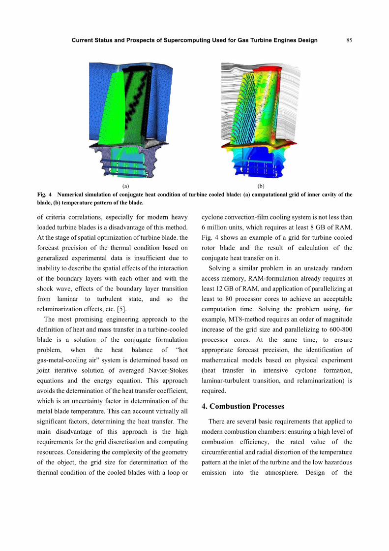
Fig. 4 Numerical simulation of conjugate heat condition of turbine cooled blade: (a) computational grid of inner cavity of the blade, (b) temperature pattern of the blade.
of criteria correlations, especially for modern heavy
loaded turbine blades is a disadvantage of this method.
At the stage of spatial optimization of turbine blade. the
forecast precision of the thermal condition based on
generalized experimental data is insufficient due to
inability to describe the spatial effects of the interaction
of the boundary layers with each other and with the
shock wave, effects of the boundary layer transition
from laminar to turbulent state, and so the
relaminarization effects, etc. [5].
The most promising engineering approach to the
definition of heat and mass transfer in a turbine-cooled
blade is a solution of the conjugate formulation
problem, when the heat balance of “hot
gas-metal-cooling air” system is determined based on
joint iterative solution of averaged Navier-Stokes
equations and the energy equation. This approach
avoids the determination of the heat transfer coefficient,
which is an uncertainty factor in determination of the
metal blade temperature. This can account virtually all
significant factors, determining the heat transfer. The
main disadvantage of this approach is the high
requirements for the grid discretisation and computing
resources. Considering the complexity of the geometry
of the object, the grid size for determination of the
thermal condition of the cooled blades with a loop or
cyclone convection-film cooling system is not less than
6 million units, which requires at least 8 GB of RAM.
Fig. 4 shows an example of a grid for turbine cooled
rotor blade and the result of calculation of the
conjugate heat transfer on it.
Solving a similar problem in an unsteady random
access memory, RAM-formulation already requires at
least 12 GB of RAM, and application of parallelizing at
least to 80 processor cores to achieve an acceptable
computation time. Solving the problem using, for
example, MT8-method requires an order of magnitude
increase of the grid size and parallelizing to 600-800
processor cores. At the same time, to ensure
appropriate forecast precision, the identification of
mathematical models based on physical experiment
(heat transfer in intensive cyclone formation,
laminar-turbulent transition, and relaminarization) is
required.
4. Combustion Processes
There are several basic requirements that applied to
modern combustion chambers: ensuring a high level of
combustion efficiency, the rated value of the
circumferential and radial distortion of the temperature
pattern at the inlet of the turbine and the low hazardous
emission into the atmosphere. Design of the

Current Status and Prospects of Supercomputing Used for Gas Turbine Engines Design
86
combustion chamber is one of the greatest challenges
in creating a gas turbine engine. The main reason for
this is the complexity of the fuel combustion process.
First, the combustion process is affected by the quality
of fuel and oxidant (air) mixture. During atomization
and mixing of the liquid fuel, an interaction of fuel
droplets with each other and with an oxidant,
evaporation of fuel droplets, their dispersion and
coagulation are taking place. This has resulted in the
air-fuel mixture formation, which mixing quality
depends on the design features of swirlers and
atomizers in combustion chamber. Most of the design
and preliminary development of the combustion
chamber today performed using a full-scale experiment.
Methods of numerical simulation based on
KAIB―approach allow at this time to determine the
aerodynamics (losses) in the combustion chamber with
satisfactory quality. Fig. 5a presents fragments of a grid
model and Fig. 5b―the velocity pattern in the cross
section, located near the front wall.
During numerical simulation of the combustion
process, the prediction error of temperature pattern
beyond the combustion chamber in average is up to 5%
(in local areas of up to 20%) and the hazardous
emission―up to 300%. During numerical simulation,
using the engineering approach, the atomization and
mixing characteristics are taken into account indirectly
and chemical kinetics of the combustion process is
based on the consideration of 2-3 main reactions.
However, used combustion models are semi-empirical
(contain the coefficients of the model, chosen based on
model experiments), and have a limited range of
applications. Grid size of the numerical simulation of
the combustion chamber sector with atomizers and
swirlers in RANS-formulation is not less than 15 million
units. Fig. 6 shows the temperature field in the
(a) (b)
Fig. 5 Numerical simulation of aerodynamics of combustion chamber: (a) fragment of a computation grid, (b) velocity pattern.
(a) (b)
Fig. 6 Numerical simulation of the combustion process in combustion chamber: (a) temperature pattern in the combustion chamber, (b) NOx reaction rate.

Current Status and Prospects of Supercomputing Used for Gas Turbine Engines Design
87
CC (combustion chamber) of GTE and the rate of
hazardous substances formation.
The use of more advanced methods such as DES to
LES for evaluation of processes in the combustion
chamber, requires five times larger grid size in
comparison with RANS-approach and parallelization
to 1,000 cores to obtain an acceptable computation
time. Numerical simulation of the full-scale
combustion chamber increases these requirements for
another order.
5. Internal Cooling of Turbine Blade
The internal cooling of the gas turbine blade is
influenced by the channel aspect ratio, turbulator
configurations, rotational and flow parameters. The
cooling channels are either single-pass (with radial
outward flow) or multi-pass (both radial outward and
radial inward flow).
Coolant is circulated through serpentine passages
fabricated on the inside of the gas turbine blade in order
to remove heat from the blade surface. Different aspect
ratio channels are applicable to different parts of the
turbine blade as shown in Fig. 7.
A typical cooled turbine blade is shown in Fig. 8
(courtesy of Han, et al. [6]). As shown, the blade is
hollow, so cooling air can pass through it internally. A
number of traditional cooling concepts are provided in
the hollow internal passage of turbine blades which are
suitable in different portion of the blades.
Fig. 7 Gas turbine blade internal cooling channels and their applicable aspect ratios.
Fig. 8 Typical blade cooling.
5.1 Impingement Cooling
Impingement cooling is commonly used near the
leading edge of the airfoils, where the heat loads are the
greatest. With the cooling jets striking (impinging) the
blade wall, the leading edge is well suited for
impingement cooling because of the relatively thick
blade wall in this area. Impingement can also be used
near the mid-chord of the blades. The effect of jet-hole
size and distribution, cooling channel crosssection, and
target surface shape all have significant effects on the
heat transfer coefficient distribution. It has been shown
by Metzger, et al. [7] that, multiple jets perform very
differently from a single jet striking a target surface.
They concluded that, for multiple jets, the Nusselt
number is strongly dependent on the Reynolds number.
florschuetz and Su [8] reported that, cross-flow
decreases the overall heat transfer from the
impingement surface. Because the enhancement from
the impingement jets is much greater than the
convective enhancement, the overall Nusselt numbers
decrease in cross-flow.

Current Status and Prospects of Supercomputing Used for Gas Turbine Engines Design
88
5.2 Pin-Fin Cooling
Due to manufacturing constraints in the very narrow
trailing edge of the blade, pin-fin cooling is typically
used to enhance the heat transfer in this region. The
pins typically have a height-to-diameter ratio between
0.5 and 4. In a pin-fin array, heat is transferred from
both the smooth channel endwall and the numerous
pins. Flow around the pins in the array is comparable to
flow around a single cylinder. As the coolant flows past
the pin, the flow separates and wakes are shed
downstream of the pin. In addition to this wake
formation, a horseshoe vortex forms just upstream of
the base of the pin, and the vortex wraps around the
pins. This horseshoe vortex creates additional mixing,
and thus enhanced heat transfer. Many factors must be
considered when investigating pin-fin cooling. The
type of pin-fin array and the spacing of the pins in the
array, the pin size and shape have a profound impact on
the heat transfer in the cooling passage. Because
pin-fins are commonly coupled with trailing edge
ejection, the effect of this coolant extraction must also
be considered.
5.3 Pin Array and Partial Length Pin Arrangement
There are two array structures commonly used. One
is the inline array and the other is the staggered array.
Fig. 9 shows a typical experimental test model with
a staggered array of pin-fins. Metzger, et al. [9]
used staggered arrays of circular pins with 1.5-5 pin
Fig. 9 A typical test model and secondary flow for pin-fin cooling studies.
diameter spacing in a rectangular channel. A closer
spaced array (smaller x/D) shows a higher heat
transfer coefficient. Chyu, et al. [10] showed that, the
heat transfer coefficient on the pin surface for both
arrays is consistently higher than that of the channel
endwall. The pin surface heat transfer is observed to be
10%-20% higher for the presented case.
5.4 Effect of Pin Shape and Array Orientation
Metzger, et al. [11] reported the effect of flow
incident angle on oblong pins. All incident angles
except 90° yield higher Nusselt numbers than circular
pins. The γ = 90° array yields significantly lower
Nusselt numbers. The γ = ±30° array has the highest
Nusselt numbers, about 20% higher than the circular
pin array on the average. Except for γ = 90°, the
pressure drop for oblong pins are significantly higher
than circular pins because of flow turning due to
oblong pins. Chyu [12] studied the effect of a fillet at
the base of the cylindrical pin. It is interesting to note
that the fillet cylinder inline formation has better heat
transfer than the straight cylinders in the inline
formation. Chyu, et al. [13] used cube and diamond
shaped pins and reported that, cube-shaped pins have
the highest mass transfer coefficients among the shapes
considered and round pins have the lowest mass
transfer coefficients. Corresponding pressure loss
coefficients are higher for the cube and diamond
shaped pins relative to the circular pins.
6. Requirements to Computing Resources
Improving accuracy of prediction of aerodynamic
processes, heat and mass transfer and combustion in
gas turbine engines can be achieved by:
Experimental study of the factors affecting the
state of the boundary layer in the turbo-machine
wheelspace, processes of atomization and mixing of
the fuel;
Develop reduced models of chemical kinetics,
describing the process of fuel combustion;
Development of mathematical models on the basis
on the experimental studies;

Current Status and Prospects of Supercomputing Used for Gas Turbine Engines Design
89
Table 1 Computing power required for problem solving of engineering analysis during GTE design by LES/DES eddy simulation methods.
Problem Grid size (million cells) Required memory (Gb) Number of processor cores
Steady Unsteady Steady Unsteady Steady Unsteady
Aerodynamics of turbo-machine uncooled stage (sector 10-12°)
5 9 7 13 35 63
Aerodynamics of turbo-machine cooled stage (sector 10-12°)
30 54 42 75 210 380
Conjugate heat and mass transfer 50 90 70 125 350 630
Aerodynamics and combustion in combustion chamber (atomizer, sector 20°)
75 135 105 190 525 950
Improving of problem-solving techniques based
on mentioned models, ensured parallelism (thousands
and tens of thousands of processor cores) on computers
with distributed memory.
The above requirements for computing resources,
meeting of which allows you to move to a more precise
definition of GTE design parameters by using
computational methods, summarized in Table 1. The
data on the dimensions of various problems available
from experiments carried out by TURBOMACHIN
company. Number of processor cores is determined by
a rule of thumb, proven-based on TURBOMACHIN
practical experience, according to which the optimal
price/performance ratio balance of the system is
achieved when a one single core for every 0.2 Gb of
memory is assigned. Upon that all problems are steady
const and unsteady const formulated.
It should also be noted that, in each case, the
computation of the single sector of engine wheelspace
is considered. For computation of the entire (360°
sector) wheelspace, an adequate number of times
increasing of required resources is needed. For
example, for complete unsteady calculation of
combustion chamber 2.5 Tb of RAM and a 12,350
processor cores are required, that at today’s level of
development of microprocessor technology, roughly
equivalent to the system capacity of 150 teraflops.
Represented data indicates the potential limitations
that, national GTE designers, maintaining competence
up to the world standards, faced. In addition to the
mentioned above challenges of the experimental
studies of various processes and the development of
new mathematical models based on them, the
development of numerical methods and program
coding of these methods that supports the efficient
parallelization to 1,000-10,000 cores are is required. It
is worthy of note that, at present time, the domestic
software products for the computational study of
aerodynamics of impeller machines, heat and mass
transfer and combustion processes are not available,
industry companies are forced to use foreign
commercial software packages that allow effective
parallelization for no more than 100 cores. At the same
time, leading international airspace companies have
their own proprietary software that allows solving
these tasks.
7. Multicriteria Optimization
Multicriteria optimization allows by means of a
calculation find the most effective combination of
product parameters before starting the manufacturing
of prototype models. Let us without loss of generality
consider the multicriteria minimizing problem with
independent variables, п objectives, Р inequality
constraints and q equality constraints [14]:
Minimize (1)
Subject to g 0, 0
where, х = , … , , ―decision vector
(independent variables), X―parameter space,
, … , ―objectives,
, … , ―inequality constraints,
h , … , ―equality constraints.

Current Status and Prospects of Supercomputing Used for Gas Turbine Engines Design
90
Decision vector ―dominates the vector
(symbolyzed by if 1, … , :
1, … , : . Vector
is called nondominated ′ if in ′ there is no
vector dominated a. set of decisions X', such that: ′ ′: : ′ ′
′
where, 0, 0, is called local Pareto―optimal
set. X' is a global Pareto―optimal set if ′
′: : a a′. Thus, the problem of multi-criteria optimization
resolves itself to a determination of a global
Pareto―optimal solution set. Up to the date, a number
of multi-criteria optimization methods, based on the
nonlinear programming, genetic algorithms, etc., that
used, among others, in the design of gas turbine
engines, is known. One of the most efficient algorithms
for multi-criteria constrained optimization is genetic
algorithm Non-dominated Sorting Genetic Algorithm
NSGA (non-dominated sorting genetic algorithm)-II [15].
The exception of this algorithm is that, at each step of
the calculation, a new population of N solutions
generated, each of them the functions , ,
. must be calculated. Population of 100 decisions,
which is evolving for 500 generations, is a typical
feature. Easy to estimate that, in this case, 50,000
evaluations of function , , is
required. Thus, for practical reasons, in order to
achieve a reasonable computation time, a method for
identifying of Pareto―optimal solution set for at least
500 calculations of accurate models of the studied
correlations must be provided. To accomplish this, the
approaches based on the use of the approximate models
instead of correlations (1), so-called response surface
models (response surface model―RSM) are used.
There is a wide range of methods for RSM
design―from the simplest, based on the least squares
method to the more sophisticated, such as the group
method of data handling, radial basis function network,
and others. Generally, such models are design based on
the training set, which created using one of the methods
of experimental design (design of experiment―DOE).
Use of these techniques allows reducing the required
amount of evaluations of function , and
by two orders of magnitude [16].
Based on the data shown in Table 1, the
dimensionality of the multi-criteria optimization
problem should be assessed.
For example, for the engine SaM146, jointly
designed by TURBOMACHINE and Snecma (France)
and having a single stage fan, three stage low-pressure
compressor, 6 stage high pressure compressor and,
respectively, 1 and 3 stage high and low pressure
turbines, the single evaluations of the function ,
and (calculation of the sector using the
unsteady formulation) can be performed by a system
with 0.65 Tb of RAM and 2,800 processors in 40 h.
This estimate obtained by counting the total number of
floating-point operations to be performed to calculate
all the elements of introduced design and evaluation of
performance of mentioned system (about 33 teraflops).
It is possible to estimate that, with such formulation,
using RSM (500 calculations of correlations (1)), the
complete optimization of the product design would
take 2.3 years. Complete unsteady calculation of such
engine of 360° sector (with the appropriate software)
would take more than 60 h by a system that has 11 Tb
of RAM and 53,750 processors (630 teraflops). Design
optimization, based on approximate models, would
take more than 4 years, which is comparable to the
design cycle of a new engine (7 years). It should be
noted that, these estimates provide a lower bound of the
time required, because in addition to the above studies
should be the blade separation calculations, bird strike,
acoustic calculations, etc. should be performed, that
was not taken into consideration.
In addition, it should be noted that, the robustness of
determined optimal solution (robust analysis) currently
becomes the area of growing attention. In the real
world, independent variables X can have stochastic
deviations from the values, which determined as the
optimal values . This may be a result of

Current Status and Prospects of Supercomputing Used for Gas Turbine Engines Design
91
deviations in the manufacturing process, which in its
turn leads to a change of geometrical parameters or the
chemical composition or product parts. That is why
very important to estimate the impact of random
variations X in regard of their probabilistic
characteristics on the final value , in particular,
using Monte Carlo method. Accordingly, all
calculations must be performed ∏ times, where
―the vector, containing the number of variations of
components of the vector X.
Therefore, it may be concluded that, even the use of
petascale performance systems will not solve the
problems of optimizing of the whole engine in the
transient regime and investigate the robustness of
determined optimal solution using models
LES/DES/DNS (direct numerical simulation). It is
obvious that, in the near future, the optimization
problems will be solved whether for its specific
elements or for the whole product, but using simplified
models.
8. Conclusions
From the presented above follows, that the challenge
of maintaining of up to the world standards competence
in the design of GTE requires significant investments,
in a first place, in creation of the experimental base for
the study of aerodynamics of impeller machines, heat
and mass transfer and combustion, and, secondly, in
creation of the national software packages for
engineering analysis working effectively in an
environment with hundreds and thousands of cores.
Advanced gas turbines operating at extremely high
temperatures, it is necessary to implement various
cooling methods, so the turbine blades survive in the
path of the hot gases. Simply passing coolant air
through the airfoils does not provide adequate cooling;
therefore, it is necessary to implement techniques that
will further enhance the heat transfer from the airfoil
walls. The internal heat transfer can be enhanced with
jet impingement, pin-fin cooling and internal passages
lined with turbulence promoters. The heat transfer
distribution in cooling channels with turbulators has
been studied for many years because a number of
factors combine to affect the heat transfer.
References
[1] Merchant, A., Kerrebrock, J. L., Adamczyk, J. J., and Braunchidel, E. 2002. “Experimental Investigation of a High Pressure Ratio Aspirated Fan Stage.” Presented at the ASME Turbo Expo 2004, Vienna, Austria.
[2] Lee, K. 2004. Basics CAD (SAL/CAM/CAE). SPb.: Peter, 560.
[3] Prahalad, C. K., and Hamel, G. 1990. “The Core Competence of the Corporation.” Harvard Business Review 66 (May-June): 79-90.
[4] Shmotin, N. 2005. Numerical Simulation of Transient Phenomena in Gas Turbine Engines. Moscow: Innovation Engineering, 536.
[5] Shmotin, N. 2007. “Influence of the Mathematical Model to Predict the Reliability of the Heat Transfer Coefficient on the Surface of the Turbine Blade.” Interdisciplinary Scientific and Technical Journal Conversion in Mechanical Engineering 4-5 (83-84): 48-55.
[6] Han, J. C., Dutta, S., and Ekkad, S. V. 2000. Gas Turbine Heat Transfer and Cooling Technology. New York: Taylor & Francis, Inc.
[7] Metzger, D. E., Florschuetz, L. W., Takeuchi, D. I., Behee, R. D., and Berry, R. A. 1979. “Heat Transfer Characteristics for Inline and Staggered Arrays of Circular Jets with Crossflow of Spent Air.” ASME Journal of Heat Transfer 101 (3): 526-31.
[8] Florschuetz, L. W., and Su, C. C. 1987. “Effects of Crossflow Temperature on Heat Transfer within an Array of Impinging Jets.” ASME Journal of Heat Transfer 109 (1) 74-82.
[9] Metzger, D. E., Berry, R. A., and Bronson, J. P. 1982. “Developing Heat Transfer in Rectangular Ducts with Staggered Arrays of Short Pin Fins.” ASME Journal of Heat Transfer 104 (4): 700-6.
[10] Chyu, M. K., Hsing, Y. C., Shih, T. I. P., and Natarajan, V. 1998. “Heat Transfer Contributions of Pins and Endwall in Pin-Fin Arrays: Effects of Thermal Boundary Condition Modeling.” ASME Paper No. 98-GT-175.
[11] Metzger, D. E., Fan, S. C., and Haley, S. W. 1984. “Effects of Pin Shape and Array Orientation on Heat Transfer and Pressure Loss in Pin Fin Arrays.” ASME Journal of Engineering for Gas Turbines and Power 106 (1): 252-7.
[12] Chyu, M. K. 1990. “Heat Transfer and Pressure Drop for Short Pin-Fin Arrays with Pin-Endwall Fillet.” ASME J. of Heat Transfer 112 (4): 926-32.
[13] Chyu, M. K., Hsing, Y. C., and Natarajan, V. 1998.

Current Status and Prospects of Supercomputing Used for Gas Turbine Engines Design
92
“Convective Heat Transfer of Cubic Fin Arrays in a Narrow Channel.” ASME Journal of Turbomachinery 120 (2): 362-7.
[14] Liu, G. P., Yang, J. B., and Whidborne, J. F. 2003. Multi-objective Optimization and Control. Baldock, England: Research Studies Press Ltd., 330.
[15] Deb, K. S., Agrawal, A. P., and Meyarivan, T. 2000. “A
Fast Elitist Non-sorting Algorithm for Multi-objective: NASA-II.” In Proceedings of the Parallel Problem Solving from Nature VI, 849-58.
[16] Zelenkov, Y. A. 2010. “The Method of Multi-criteria Optimization Based on Approximate Models of the Object.” Numerical Methods and Programming 11 (2): 92-102.