Current Sensorstechnical Guide & Specifications
9
BICRON Electronics Company CUR R ENT SENSORS T E CH NIC AL GUIDE & S PE CI FIC A T IONS Standard & Custom AC Current Sensors for OE M Applications w w w . c u r r e n t s e n s o r . c o m
Transcript of Current Sensorstechnical Guide & Specifications

7/28/2019 Current Sensorstechnical Guide & Specifications
http://slidepdf.com/reader/full/current-sensorstechnical-guide-specifications 1/8
BICRON Electronics Company
CURRENT SENSORS TECHNICAL GUIDE & SPECIFICATIONS
Sta nda rd & Custom AC Current Sensors for OEM Applica tions
w w w . c
u r r e
n t s e n
s o r . c o m

7/28/2019 Current Sensorstechnical Guide & Specifications
http://slidepdf.com/reader/full/current-sensorstechnical-guide-specifications 2/8
C S U P
P L Y
D C R E L A Y
BICRON Electronics Company
The BICRON Advantage . . .
ISO 9001 Certified
A leader in electronic design a nd
manufac turing since 19 64
Sta te-of-the-ar t engineering developm ent tools offering:
• Finite element a na lysis • Circuit simula tion
Products designed to m eet na tional and internat ional safety standards
Current transformers with window sizes from 0.02 to 3 50 in 2 and current rat ings to 10,000A
Long history servicing m any of the Fortune 5 00 companies
Capabilities to design/m anufacture va lue added assemblies
Our goa l is to exceed our custom ers’ expectation s by constantly seeking bet ter wa ys to deliver service and va lue.
50 Barlow Street,Canaan,CT 06018 Tel:860-824-5125,Fax:860-824-1137email: [email protected]
7/28/2019 Current Sensorstechnical Guide & Specifications
http://slidepdf.com/reader/full/current-sensorstechnical-guide-specifications 3/8
Bold: Factory Stock Item • Italic:Check with Factory •XXXX:Not Available
BICRON Electronics Company ISO9001 Certified
www.currentsensor.com 3
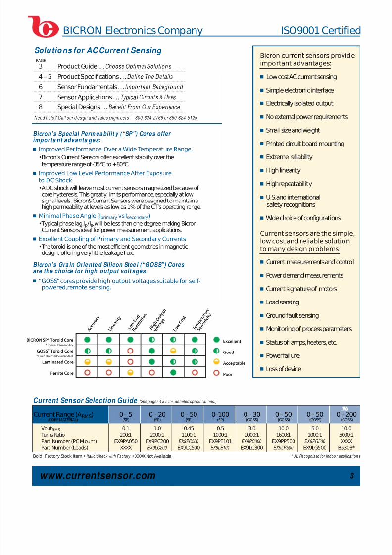
Solutions for AC Current Sensing
3 Product Guide ...Choose Optim al Solution s
4–5 Product Specifications ...Define The Details
6 Sensor Fundamentals ...Important Background
7 Sensor Applications ...Typica l Circuit s & Uses 8 Special Designs ...Benefit From Our Experience
Need help? Call our d esign a nd sales engin eers — 800-624-2766 or 860-824-5125
PAGEBicron current sensors provideimportant advantages:
Ⅲ Low cost ACcurrent sensing
Ⅲ Simple electronic interface
Ⅲ Electrically isolated output
Ⅲ No external power requirements
Ⅲ Small size and weight
Ⅲ Printed circuit board mounting
Ⅲ Extreme reliability
Ⅲ High linearity
Ⅲ High repeatability
Ⅲ U.S.and internationalsafety recognitions
Ⅲ Wide choice of configurations
Current sensors are the simple,low cost and reliable solutionto many design problems:
Ⅲ Current measurements and control
Ⅲ Power demand measurements
Ⅲ
Current signature of motors
Ⅲ Load sensing
Ⅲ Ground fault sensing
Ⅲ Monitoring of process parameters
Ⅲ Status of lamps,heaters,etc.
Ⅲ Power failure
Ⅲ Loss of device
Bicron’s Special Perm ea bilit y (“SP”) Cores offer importa nt advanta ges:
Ⅲ Improved Performance Over a Wide Temperature Range.
•Bicron’s Current Sensors offer excellent stability over thetemperature range of -35°C to +80°C.
Ⅲ Improved Low Level Performance After Exposureto DCShock
•A DCshock will leave most current sensors magnetized because of
core hysteresis. This greatly limits performance,especially at lowsignal levels. Bicron’s Current Sensors were designed to maintain ahigh permeability at levels as low as 1% of the CT’s operating range.
Ⅲ Minimal Phase Angle (Iprimary vs Isecondary)
•Typical phase lag,Ip/Is,will be less than one degree,making BicronCurrent Sensors ideal for power measurement applications.
Ⅲ Excellent Coupling of Primary and Secondary Currents
•The toroid is one of the most efficient geometries in magneticdesign, offering very little leakage flux.
Bicron’s Gra in Orie nte d Silicon Stee l (“GOSS”) Cores are the choice for high output volt ages.
Ⅲ “GOSS”cores provide high output voltages suitable for self-powered,remote sensing.
Current Sensor Selection Gu ide (See pages 4 & 5 for detailed specifications.)
BICRON SP* Toroid Core
GOSS* Toroid Core
Laminated Core
Ferrite Core
* Grain Oriented Silicon Steel
* Special Permeability
A c c u r a
c y
L o w
E n d
R e s o l u t i o n
H i g h O u t p u t
V o l t a
g e
L o w
C o s t
T e m p e r a t u r e
S e n s i t i v i t y
L i n
e a r i t y
Excellent
Good
Acceptable
Poor
Current Range (ARMS) 0 – 5 0 – 20 0 – 50 0–100 0 – 30 0 – 50 0 – 50 0 – 200(CORE MATERIAL) (SP) (SP) (SP) (SP) (GOSS) (GOSS) (GOSS) (GOSS)
VoutRMS 0.1 1.0 0.45 0.5 3.0 10.0 5.0 10.0
Turns Ratio 200:1 2000:1 1100:1 1000:1 1000:1 1600:1 1000:1 5000:1Part Number (PCMount) EX9PA050 EX9PC200 EX9PC500 EX9PE101 EX9PC300 EX9PP500 EX9PG500 XXXXPart Number (Leads) XXXX EX9LC200 EX9LC500 EX9LE101 EX9LC300 EX9LP500 EX9LG500 B5303*
* UL Recognized for indoo r application s
7/28/2019 Current Sensorstechnical Guide & Specifications
http://slidepdf.com/reader/full/current-sensorstechnical-guide-specifications 4/8
www.currentsensor.com 4
BICRON Electronics Company ISO9001 Certified
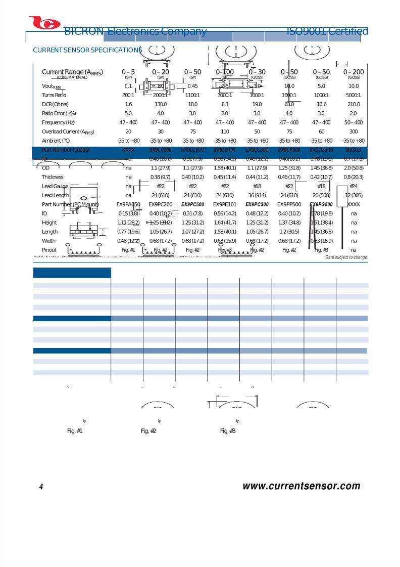
CURRENT SENSOR SPECIFICATIONS
Bold: Factory Stock Item • Italic:Check with Factory •XXXX:Not Available •All Sizes shown in inches (mm)
.80(20.3)
.63 (16) .40 (10.2)
.05 (1.3)
.20 (5.1)
IDID
IDHeight
LeadLength
Length
1.25(31.8)
2
4
1
3
Thickness
.25 (6.4)
.60(15.2)
.68(17.2)
Height
.03 (0.8) .04 (1.0)
.15 (3.8)
Length
2
3
1
4
.48 (12.2)
.71(18.0)
.77(19.6)
.50(12.7)
.30(7.62)
.20/.15 (5.1/3.8)
1.11(28.2)
.29 (7.4)
1
2 3
4
.15 (3.8) dia.
.03 (.76) sq.
OD
3 2
Ip
2 1
Ip
2 1
Ip
Fig.#1 Fig.#3Fig.#2
Data subject to change.
Current Range (ARMS) 0 – 5 0 – 20 0 – 50 0–100 0 – 30 0 – 50 0 – 50 0 – 200(CORE MATERIAL) (SP) (SP) (SP) (SP) (GOSS) (GOSS) (GOSS) (GOSS)
VoutRMS 0.1 1.0 0.45 0.5 3.0 10.0 5.0 10.0
Turns Ratio 200:1 2000:1 1100:1 1000:1 1000:1 1600:1 1000:1 5000:1
DCR(Ohms) 1.6 130.0 18.0 8.3 19.0 63.0 16.6 210.0
Ratio Error (±%) 5.0 4.0 3.0 2.0 3.0 4.0 3.0 2.0
Frequency (Hz) 47 – 400 47 – 400 47 – 400 47 – 400 47 – 400 47 – 400 47 – 400 50 – 400
Overload Current (ARMS) 20 30 75 110 50 75 60 300
Ambient (°C) -35 to +80 -35 to +80 -35 to +80 -35 to +80 -35 to +80 -35 to +80 -35 to +80 -35 to +80
Part Number (Leads) XXXX EX9LC200 EX9LC500 EX9LE101 EX9LC300 EX9LP500 EX9LG500 B5303
ID na 0.40 (10.2) 0.31 (7.9) 0.56 (14.2) 0.48 (12.2) 0.40(10.2) 0.78 (19.8) 0.7 (17.8)
OD na 1.1 (27.9) 1.1 (27.9) 1.58 (40.1) 1.1 (27.9) 1.25 (31.8) 1.45 (36.8) 2.0 (50.8)
Thickness na 0.38 (9.7) 0.40 (10.2) 0.45 (11.4) 0.44 (11.2) 0.46 (11.7) 0.42 (10.7) 0.8 (20.3)
Lead Gauge na #22 #22 #22 #18 #22 #18 #24
Lead Length na 24 (610) 24 (610) 24 (610) 36 (914) 24 (610) 20 (508) 12 (305)
Part Number (PCMount) EX9PA050 EX9PC200 EX9PC500 EX9PE101 E X9PC300 EX9PP500 EX9PG500 XXXX
ID 0.15 (3.8) 0.40 (10.2) 0.31 (7.8) 0.56 (14.2) 0.48 (12.2) 0.40 (10.2) 0.78 (19.8) na
Height 1.11 (28.2) 1.25 (31.2) 1.25 (31.2) 1.64 (41.7) 1.25 (31.2) 1.37 (34.8) 1.51 (38.4) na
Length 0.77 (19.6) 1.05 (26.7) 1.07 (27.2) 1.58 (40.1) 1.05 (26.7) 1.2 (30.5) 1.45 (36.8) na
Width 0.48 (12.2) 0.68 (17.2) 0.68 (17.2) 0.63 (15.9) 0.68 (17.2) 0.68 (17.2) 0.63 (15.9) na
Pinout Fig.#1 Fig.#2 Fig.#2 Fig.#3 Fig.#2 Fig.#2 Fig.#3 na

7/28/2019 Current Sensorstechnical Guide & Specifications
http://slidepdf.com/reader/full/current-sensorstechnical-guide-specifications 5/8
BICRON Electronics Company ISO9001 Certified
www.currentsensor.com 5
CURRENT SENSOR PERFORMANCE INFORMATION
0 10 20 30 40 50
15
12
9
6
3
0
Output Voltage vs. Buss Current: 0 — 50A
800Ω
400Ω
Buss Current Ip (Amps)
600Ω
O u t p u t V o l t a g e
V s
( V o
l t s )
R a t i o E r r
o r ± 6 %
R a t i o
E r r o r ±
5 %
R a t i o
E r r o r
± 4 %
EX9LP500 / EX9PP500
0 10 20 30 40 50
10
8
6
4
2
0
Output Voltage vs. Buss Current: 0 — 50A
300Ω
100Ω
Buss Current Ip (Amps)
200Ω
O u t p u t V o l t a g e
V s
( V o
l t s )
R a t i o
E r r o r
± 8 %
R a t i o
E r r o r ±
5 %
R a t i o E
r r o r ±
3 %
EX9LG500 / EX9PG500
0 40 60 80 10020
1.0
0.8
0.6
0.4
0.2
0.0
Buss Current Ip (Amps)
O u t p u t V o l t a g e V s
( V o l t
s )
Output Voltage vs. Buss Current: 0 — 100A
20Ω
10Ω
5Ω
R a t i o
E r r o r
± 2 %
R a t i o
E r r o r ±
2 %
R a t i o E
r r o r ± 2
%
EX9LE101 / EX9PE101
0 100 150 20050
10
8
6
4
2
0
Output Voltage vs. Buss Current: 0 — 200A
500Ω
250Ω
Buss Current Ip (Amps)
333Ω
O u t p u t V o l t a g e
V s
( V o l t s )
R a t i o
E r r o r ±
2 %
R a t i o
E r r o r
± 2 %
R a t i o
E r r o r
± 2 %
B5303
0 10 20 30 40 50
0.70
0.60
0.50
0.40
0.30
0.20
0.10
0.00
Output Voltage vs. Buss Current: 0 — 50A
24Ω
10Ω
Buss Current Ip (Amps)
15Ω
O u t p u t V o l t a g e
V s
( V o l t s )
R a t i o
E r r o r ±
3 %
R a t i o
E r r o r ±
3 %
R a t i o
E r r o r
± 3 %
EX9LC500 / EX9PC500
0 5 10 15 20 25 30
4.0
3.5
3.0
2.5
2.0
1.5
1.0
0.5
0.0
Output Voltage vs. Buss Current: 0 — 30A
200Ω
100Ω
Buss Current Ip (Amps)
150Ω
O u t p u t V o l t a g e
V s
( V
o l t s )
EX9LC300 / EX9PC300
R a t i o
E r r o r
± 7 %
R a t i o
E r r o r ±
5 %
R a t i o
E r r o r
± 3 %
0 10 15 205
1.8
1.6
1.4
1.2
1.0
0.8
0.6
0.4
0.2
0.0
Output Voltage vs. Buss Current: 0 — 20A
300Ω
100Ω
700Ω
Buss Current Ip (Amps)
167Ω
O u t p u t V o l t a g e
V s
( V o
l t s )
R a t i o
E r r o r
± 4 %
R a t i o
E r r o r
± 4 %
R a t i o
E r r o r ±
4 %
R a t i o E
r r o r ±
4 %
EX9LC200 / EX9PC200
0 1.0 2.0 3.0 4.0 5.0
0.12
0.10
0.08
0.06
0.04
0.02
0.00
Output Voltage vs. Buss Current: 0 — 5A
8Ω20Ω 4Ω
Buss Current Ip (Amps)
O u t p u t V o l t a g e
V s
( V o l t s )
R a t i o
E r r o r
± 5 %
R a t i o
E r r o
r ± 5
%
R a t i o
E r r o r
± 5 %
EX9PA050
Data subject to change.
BICRON SPECIAL PERMEABILITY (SP) CORES BICRON GRAIN ORIENTED SILICON STEEL (GOSS) CORES

7/28/2019 Current Sensorstechnical Guide & Specifications
http://slidepdf.com/reader/full/current-sensorstechnical-guide-specifications 6/8
BICRON Electronics Company ISO9001 Certified
www.currentsensor.com 6
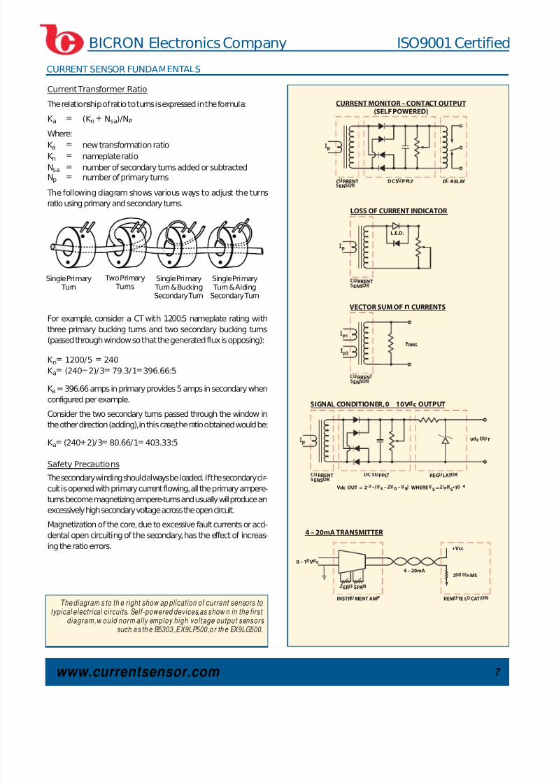
CURRENT SENSOR FUNDAMENTALS
Introduction
Current transformers are used to measure or monitor the currentin an AC power circuit.
The ratio of the primary current to the secondary current is a func-tion of the turns ratio and the loss associated with the conversion.For example,copper losses in a voltage transformer affect the volt-age regulation. In a current transformer,copper losses cause anincrease in core loss,or a reduction in accuracy.
Accuracy
ISN2 IPN1 – IMN1
Where:
ISN2 the secondary current the number of turns
IPN1 primary current the number of turns
IMN1 ampere-turns required for core loss The excitation current, (IM),determines the maximum accuracythat can be achieved with a current transformer. This current isdefined as that portion of the primary current which satisfies thecore losses.While the excitation current can never be eliminated,itcan,in some cases,be compensated by adjusting the turns ratio.
If it were not for the core losses,the primary and secondary cur-rents would be exactly inversely proportional to the number of turns in the two windings. The error due to leakage flux is negligi-ble in most current transformers using toroidal cores,and utilizingproper winding methods.
Burden
The total impedance of the devices connected to the secondaryterminals (leads, meters,relay coil, resistance,etc.) of a currenttransformer is defined as its burden.Burden is expressed in volt-amperes (VA) or in ohms impedance.
Burden resistance should be kept as low as possible,since anincrease in burden increases the core flux density (B), therebyincreasing the core loss.
Utilizing Faraday's Law:
B108 IS(R WR)
4.44 f N2 AC
Where:
IS secondary current (amps)
R burden (ohms)
WR winding resistance
f frequency (Hz)
N2 turns
AC cross section area (cm2)
B flux density (Gauss)
Note: IS (IPN1 IMN1)/ N2
Ratio-Correction Factor
The ratio-correction factor indicates the percentage amount that
the secondary current value differs from the correct value.
Phase Angle Error
The phase angle error is not applica-
ble to current actuated devices but
will affect the accuracy of devices
that respond to the products, the
sums or difference of currents.
Polarity
Current transformer polarity can be
defined by permanent markings
(typicallyH1– X1)or polarity dots.
Short-Time Current Limits
Current transformers may have to carry very large currents in theevent of short circuit,motor starting,etc. The windings heat very
rapidly at a rate nearly proportional to the square of the current.The
majority of the heat will be stored in the copper.The short-time cur-
rent limit is the time to raise the temperature of the winding to
105 C,considering ambient temperature.
Cont inues on Page 7 >
10,000
1,000
100
10
1•10-6 1•10-5 1•10-4 1•10-3 1•10-2 1•10-1
Core Loss — Watts Per Pound
F l u x D e n s i t y — G
a u s s
Excitation Current
(Reflected to Primary)
=core loss
secondary voltage N1/N
2
Where core loss = watts/lb lb of core
PhaseAngle
lp = 3000
ls = 5
H1
X1
Typical Core Loss vs.Flux D ensity Gra ph.
7/28/2019 Current Sensorstechnical Guide & Specifications
http://slidepdf.com/reader/full/current-sensorstechnical-guide-specifications 7/8
CURRENT SENSOR FUNDAMENTALS
BICRON Electronics Company ISO9001 Certified
www.currentsensor.com 7
CURRENT MONITOR – CONTACT OUTPUT
(SELF POWERED)
C RRENTEN
DC S PPLY D RELAY
VECTOR SUM OFn CURRENTS
RRENEN
ERMS
4 – 20mA TRANSMITTER
0 – 1 V c
ER SPA
INSTR MENT AM REM TE L CATI
4 – 20mA
+Vcc
2 HMS
LOSS OF CURRENT INDICATOR
RRENTENS
L.E.D.
SIGNAL CONDITIONER, 0 10V c OUTPUT
RRENTENS
PPL REG LAT
V c T
Vdc OUT = 2-2 • S – D – R WHERE S = S•1 4
Current Transformer Ratio
The relationship of ratio to turns is expressed in the formula:
K a (K n Nsa)/NP
Where:K a new transformation ratio
K n nameplate ratio
Nsa number of secondary turns added or subtractedNp number of primary turns
The following diagram shows various ways to adjust the turnsratio using primary and secondary turns.
For example, consider a CT with 1200:5 nameplate rating withthree primary bucking turns and two secondary bucking turns(passed through window so that the generated flux is opposing):
K n 1200/5 240
K a (240 2)/3 79.3/1 396.66:5
K a= 396.66 amps in primary provides 5 amps in secondary whenconfigured per example.
Consider the two secondary turns passed through the window inthe other direction (adding),in this case,the ratio obtained would be:
K a (240 2)/3 80.66/1 403.33:5
Safety Precautions
The secondary winding should always be loaded.If the secondary cir-cuit is opened with primary current flowing,all the primary ampere-turns become magnetizing ampere-turns and usually will produce anexcessively high secondary voltage across the open circuit.
Magnetization of the core,due to excessive fault currents or acci-dental open circuiting of the secondary,has the effect of increas-
ing the ratio errors.
Single Primary Turn
Two Primary Turns
Single Primary Turn & BuckingSecondary Turn
Single Primary Turn & AidingSecondary Turn
The diagram s to th e right show ap plication of current sensors to typical electrical circuits. Self-powered devices,as show n in the f irst
diagram,w ould norm al ly employ high vol tage output sensors such a s th e B5303 ,EX9LP500,o r th e EX9LG500.

7/28/2019 Current Sensorstechnical Guide & Specifications
http://slidepdf.com/reader/full/current-sensorstechnical-guide-specifications 8/8
BICRON Electronics Company ISO9001 Certified
BICRON Electronics Company50 Barlow Street,Canaan,CT 06018 • Tel:860-824-5125,1-800-624-2766 • Fax:860-824-1137 • email:[email protected]
Fo r f a s t , u p t o d a t e i n f o r m a t i o n a n d c o m p l e t e p r o d u c t d a t a s h e et s , v i s i t o u r w e b si t e a t www.currentsensor.com .
Limitation of Applicable Liability: Bicron Electronics Company assumes the buyer to be an expert in his intended application of Bicron Electronics products.Bicron Electronics claims no special expertise in theapplication of its products in the buyers equipment.Bicron Electronics accepts no responsibility in the buyer’s selection and use of Bicron Electronics products.Buyer’s interpretation and implementation of application suggestions and recommendations by Bicron Electronics,general or specific,transmitted verbally or in writing,published or unpublished,is strictly at the buyers own risk.
072001 12504
Since our inception in 1964,Bicron Electronics has been aleader in designing and manufacturing coil based electricalproducts and assemblies to meet specific requirements.TodayBicron is a preferred supplier of specialized current sensors tomany of the world’s largest and best known electrical equip-ment manufacturers. Our manufacturing program includeswindow sizes up to 350 square inches with current ratings upto 10,000A and current ratios from 10:1 to 6000:5.Bicron cur-rent sensors are UL recognized for indoor application.
Because of our extensive design and manufacturing experi-ence,we have a very large collection of proven designs whichcan be used as starting points for meeting closely related newrequirements. Bicron’s “Modified Standard”program permitsus to substantially modify our standard electrical and mechan-ical specifications without incurring significant engineering ormanufacturing charges.This allows you to optimize your sys-tem without delay,at the lowest possible cost.
VALUE-ADDED ASSEMBLIES
Bicron can also be of great value when it comes to providingfinished assemblies or sub-assemblies.
We can:
Ⅲ Custom design and fabricate,typically,power supplies andconditioning equipment,battery chargers,current monitor-ing or control systems,and sub-assemblies utilizing electro-mechanical/electromagnetic devices such as solenoids,transformers,inductors and coils.
Ⅲ Produce virtually any quantity you need ... from less than a
hundred to hundreds of thousands ...all at globally compet-itive pricing.
Ⅲ Ensure highest quality and reliability,efficient workflow,verycompetitive pricing,and on-time delivery through the use of the well proven Bicron Production Management System.
Ⅲ Exceed our customers’expectations by constantly seekingbetter ways to deliver service and value.
ADDITIONAL CAPABILITIES
Bicron is well known for its expertise in designing and manufac-turing electrical coil based products covering a wide range of applications:
Ⅲ Bicron Toroidal Power and Isolation Transformers
Ⅲ Bicron High Isolation Voltage Magnetics
Ⅲ Bicron Tubular and Frame DC Solenoids
Please ask for specific literature or visit our web site atwww.BicronUSA.com.
Current t ransformer designed for moto r contro l appl icat ions
Three-phase current transformer assemb ly used in high volt age switchgear
Current sensor wit h a mu ltiple turn prim ary for a special industrial control application
Value-added Assembly
UL recognized current transformers with w in- dow sizes from 1 to 3.25 in.d ia.
UL recognized current trans- formers with win dow sizes up to 35 sq,in.
UL recognized ground faul t
sensor with a 66 sq.in .window
used in distribut ion
switchgear