
How thulium impurities impact photodarkening effect in Yb 3+ -doped fibre laser?

Ericsson Review No. 2, 200864
Introduction to passive optical networksVideo components in the service bundle call for higher bandwidth, forcing most telecommunications operators to contem-plate upgrading or completely renewing their copper-centric legacy access networks.1 Gigabit-capable passive optical networks (GPON) and Ethernet passive optical net-works (EPON) are two standards that open the door to new opportunities both for ven-dors and operators.
Major vendors, including Ericsson, have added PON technology to their broadband access portfolios, and operators around the world have shown considerable interest in de-ploying this technology in combination with VDSL2 (fiber to the cabinet, FTTC) or as res-idential access (fiber to the home, FTTH).1
The three major PON standards are BPON (broadband PON, currently only of historical interest), GPON, and EPON.4-6
BPON and its successor GPON are ITU-T recommendations sponsored by FSAN, a vendor and operator committee.7 EPON is an IEEE option developed by the
IEEE Ethernet in the First Mile (EFM) initia-tive. Given that operators are driving GPON standardization via FSAN, the GPON stan-dard reflects operator needs more directly than does EPON.
Although all three systems work on the same principle, there are several differences between them (see Table 1).
GPON evolutionAfter some minor initial deployments of BPON, the industry realized too late that a BPON-based optical distribution network (ODN) could not be incrementally upgraded to any next-generation technologies. In short, the logistics of upgrading an entire PON simultaneously were daunting, and the cost of installing a parallel upgrade PON was prohibitive. Out of this experience grew the requirement that it must be possible to make incremental next-generation upgrades on the same ODN.
There were, and still are, many candi-dates for next-generation PON systems. The ITU community thus drafted G.984.5, which reserved wavelengths for use by next- generation applications without constraining
them. By contrast, the EPON community saw bandwidth limitations as the most seri-ous problem and immediately began work on 10Gbps EPON (802.3av) as the successor to 1Gbps EPON.
The economics of real deployments also led ITU-T, encouraged by FSAN, to start working on a reach-extension standard for GPON, provisionally designated G.984.re.8
This specification allows optical amplifiers or signal regenerators to be used
to extend reach to 60km; • to increase the split ratio; or • to achieve a combination of both. •
The next-generation architecture (NGA) defines two stages of evolution (Figure 1): NGA1 and NGA2. NGA1 is compatible with GPON deployments in accordance with G.984.5. Compatibility with a GPON reach extender is also expected, but has not yet been explored in detail. It is anticipated that NGA1 systems will be commercially avail-able around 2010. Some NGA1 candidates are:
XGPON1, which supports data rates of • 10Gbps downstream and 2.5Gbps up-stream; symmetric XGPON2, which supports • 10Gbps downstream and upstream; and WDM option to overlay PONs and point-• to-point connections on the same fiber infrastructure in G.984.5 enhancement bands.
Recognizing that G.984 definitions will not be suitable forever and new developments will obviate the need for backward compat-ibility, ITU-T has not constrained NGA2 by the GPON ODN. It is anticipated that NGA2 products will be available around 2015. NGA2 may use a new fiber network, introducing in particular the ability to use dense wavelength-division multiplexing (WDM) splitters instead of power splitters to separate users via different wavelengths on the same ODN.
Long-reach PONBasic GPON systems support a maximum physical reach of 20km on a 32-way split or 10km on a 64-way split. Although this seems sufficient for most deployment cases, the industry seeks an extended link budget for two reasons:
Longer reach:• Reach-extended PONs sup-porting 100km would allow thousands of today’s central offices to be consolidated to a handful of huge metro nodes, thereby simplifying the network architecture and
Current and next-generation PONs: A technical overview of present and future PON technologyElmar Trojer, Stefan Dahlfort, David Hood and Hans Mickelsson
The authors describe the evolution of GPON and associated trends in the industry. They briefly introduce and compare current PON technologies and describe options for reach-extended GPON and next-generation ac-cess systems.
TERMS AND ABBREVIATIONS
BPON Broadband PONCDR Clock detection and recoveryDSL Digital subscriber lineEFM Ethernet in the first mileEPON Ethernet PONFEC Forward-error correctionFSAN Full-service access networkFTTC Fiber to the cabinetFTTH Fiber to the homeGPON Gigabit-capable PONIEEE Institute of Electrical & Electronics EngineersITU-T International Telecommunication Union – Telecommunication Standardization SectorNGA Next-generation architectureOA Optical amplifierOAM Operation, maintenance and administration
ODN Optical distribution networkOLT Optical line terminationOMCI ONT management control interfaceONT Optical network terminationONU Optical network unitPDFA Praseodymium-doped fiber ampliferPON Passive optical networkQD-SOA Quantum-dot SOARE Reach extenderRPT Remote protocol terminatorSDH Synchronous digital hierarchySOA Semiconductor optical amplifierTDFA Thulium-doped fiber amplifierTDM Time-division mulitplexingVDSL2 Very high-speed DSL 2WDM Wavelength-division multiplexing

Ericsson Review No. 2, 2008 65
reducing operating expenses.9 A modest increase in budget would make it possible to reach remote customers. Increased split ratio:• A split ratio of 64 or even 128 would reduce the cost per sub-scriber of a PON system.10 PON technol-ogy is being driven by the need for higher bandwidth, but low take rates also mean that the business case for high-rate services is a future promise rather than a current fact. As a consequence, operators want to serve a large number of basic users from each PON by sharing common equip-ment.
There are two basic ways of extending reach (Figure 2). A single-sided extender enhancing the optical transceiver function of the optical line termination (OLT) keeps the ODN pas-sive and allows for a limited budget increase (Figure 2, top).
An active mid-span extender (reach ex-tender, sometimes designated RE), as cur-rently drafted in G.984.re, would allow the optical trunk line to be extended to achieve a total reach of 60km. This represents the maximum logical reach of the GPON proto-col layer (Figure 2, bottom).
To succeed, a reach extender must comply with the following fundamental require-ments:
It must be cost-effective – that is, there 1. must be a business case that supports the deployment of reach extenders (cost ben-efits over keeping exchange buildings).It must be transparent to existing GPON 2. OLTs situated on the network side and op-tical network terminations (ONT) on the the user side.It must be available for early GPON de-3. ployment.
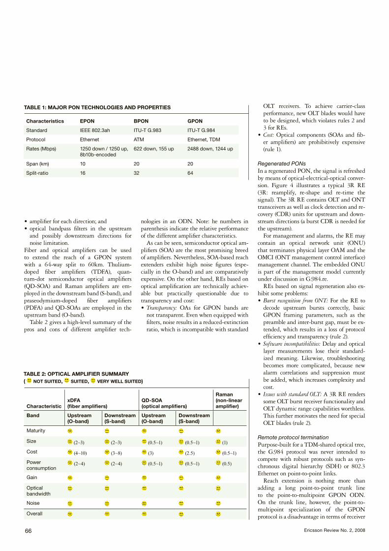
Figure 3 compares different approaches to en-hancing the performance of reach extenders.
Forward-error correction (FEC) techniques can extend reach by typically 5km. Likewise, optical amplifiers (fiber, semiconductor or distributed) can increase the link budget to 60km or more.
Optically amplified PONsOptical amplifiers (OA) can be used in GPON either to boost transmit power and receiver sensitivity on the OLT side or to work as an in-line amplifier in mid-span reach extenders.
A typical GPON RE based on amplifica-tion comprises
wavelength filters to separate upstream • and downstream signals;
Figure 2Reach-extension topologies.
Figure 1Coexistence and upgrade tracks as discussed in FSAN.
Ericsson Review No. 2, 200866
amplifier for each direction; and • optical bandpass filters in the upstream • and possibly downstream directions for noise limitation.
Fiber and optical amplifiers can be used to extend the reach of a GPON system with a 64-way split to 60km. Thulium-doped fiber amplifiers (TDFA), quan-tum-dot semiconductor optical amplifiers (QD-SOA) and Raman amplifiers are em-ployed in the downstream band (S-band), and praseodymium-doped fiber amplifiers (PDFA) and QD-SOAs are employed in the upstream band (O-band).
Table 2 gives a high-level summary of the pros and cons of different amplifier tech-
nologies in an ODN. Note: he numbers in parenthesis indicate the relative performance of the different amplifier characteristics.
As can be seen, semiconductor optical am-plifiers (SOA) are the most promising breed of amplifiers. Nevertheless, SOA-based reach extenders exhibit high noise figures (espe-cially in the O-band) and are comparatively expensive. On the other hand, REs based on optical amplification are technically achiev-able but practically questionable due to transparency and cost:
Transparency:• OAs for GPON bands are not transparent. Even when equipped with filters, noise results in a reduced-extinction ratio, which is incompatible with standard
OLT receivers. To achieve carrier-class performance, new OLT blades would have to be designed, which violates rules 2 and 3 for REs. Cost:• Optical components (SOAs and fib-er amplifiers) are prohibitively expensive (rule 1).
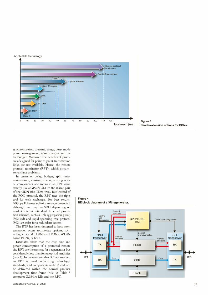
Regenerated PONsIn a regenerated PON, the signal is refreshed by means of optical-electrical-optical conver-sion. Figure 4 illustrates a typical 3R RE (3R: reamplify, re-shape and re-time the signal). The 3R RE contains OLT and ONT transceivers as well as clock detection and re-covery (CDR) units for upstream and down-stream directions (a burst CDR is needed for the upstream).
For management and alarms, the RE may contain an optical network unit (ONU) that terminates physical layer OAM and the OMCI (ONT management control interface) management channel. The embedded ONU is part of the management model currently under discussion in G.984.re.
REs based on signal regeneration also ex-hibit some problems:
Burst recognition from ONT:• For the RE to decode upstream bursts correctly, basic GPON framing parameters, such as the preamble and inter-burst gap, must be ex-tended, which results in a loss of protocol efficiency and transparency (rule 2). Software incompatibilities:• Delay and optical layer measurements lose their standard-ized meaning. Likewise, troubleshooting becomes more complicated, because new alarm correlations and suppression must be added, which increases complexity and cost. Issues with standard OLT:• A 3R RE renders some OLT burst receiver functionality and OLT dynamic range capabilities worthless. This further motivates the need for special OLT blades (rule 2).
Remote protocol terminationPurpose-built for a TDM-shared optical tree, the G.984 protocol was never intended to compete with robust protocols such as syn-chronous digital hierarchy (SDH) or 802.3 Ethernet on point-to-point links.
Reach extension is nothing more than adding a long point-to-point trunk line to the point-to-multipoint GPON ODN. On the trunk line, however, the point-to- multipoint specialization of the GPON protocol is a disadvantage in terms of receiver
TABLE 1: MAJOR PON TECHNOLOGIES AND PROPERTIES
Characteristics EPON BPON GPON
Standard IEEE 802.3ah ITU-T G.983 ITU-T G.984
Protocol Ethernet ATM Ethernet, TDM
Rates (Mbps) 1250 down / 1250 up, 8b10b-encoded
622 down, 155 up 2488 down, 1244 up
Span (km) 10 20 20
Split-ratio 16 32 64
CharacteristicxDFA (fiber amplifiers)
QD-SOA (optical amplifiers)
Raman (non-linear amplifier)
Band Upstream(O-band)
Downstream(S-band)
Upstream(O-band)
Downstream(S-band)
Maturity
Size (2~3) (2~3) (0.5~1) (0.5~1) (1)
Cost (4~10) (3~8) (3) (2.5) (0.5~1)
Power consumption
(2~4) (2~4) (0.5~1) (0.5~1) (0.5)
Gain
Optical bandwidth
Noise
Overall
TABLE 2: OPTICAL AMPLIFIER SUMMARY ( NOT SUITED, SUITED, VERY WELL SUITED)
Ericsson Review No. 2, 2008 67
synchronization, dynamic range, burst mode power management, noise margins and jit-ter budget. Moreover, the benefits of proto-cols designed for point-to-point transmission links are not available. Hence, the remote protocol terminator (RPT), which circum-vents these problems.
In terms of delay, budget, split ratio, maintenance, existing silicon, existing opti-cal components, and software, an RPT looks exactly like a GPON OLT to the shared part of the ODN (the TDM tree). But instead of the PON protocol, the RPT uses the right tool for each exchange. For best results, 10Gbps Ethernet uplinks are recommended, although one may use SDH depending on market interest. Standard Ethernet protec-tion schemes, such as link aggregation group (802.3ad) and rapid spanning tree protocol (802.1w), exist for a redundant system.
The RTP has been designed to host next-generation access technology options, such as higher speed TDM-based PONs, WDM-based PONs, or both.
Estimates show that the cost, size and power consumption of a protected remote site RPT are the same as for a regenerator but considerably less than for an optical amplifier (rule 1). In contrast to other RE approaches, an RPT is based on existing technology, standards, and components (rule 2) and can be delivered within the normal product development time frame (rule 3). Table 3 compares G.984.re REs and the RPT.
Figure 3Reach-extension options for PONs.
Figure 4RE block diagram of a 3R regenerator.

Ericsson Review No. 2, 200868
Next-generation access
Now that GPON has been standardized and is in production, the optical access commu-nity has begun discussing candidate technol-ogies for next-generation access. The high-level requirements for an NGA1 system are already clear, as follows:
Fiber-lean scenario – that is, coexistence 1. with working GPON on the same ODN. NGA1 must support upgradeability, one subscriber at a time.Major improvement in performance over 2. GPON in terms of rate and reach or split.
Shared capacity of at least 10Gbps in the downstream and 2.5 or 5Gbps in the up-stream direction.NGA1 must be highly flexibility in terms 3. of coexistence (GPON and G.984.re reach extenders), upgradeability to higher split ratios, and support of special-purpose overlays (for instance, business services).Volume cost comparable to GPON. 4.
Service overlay a la G.984.5G.984.5 defines wavelength ranges reserved for additional service signals overlaid via
WDM. In particular, it includeswavelength ranges to be reserved for future • use (Figure 5) – G.984.5 specifies three op-tional enhancement bands with option 1 in the E band (water-peak band), option 2 in the C- and L-bands, and the RF band, as option 3, for future services provided video overlay is not deployed; wavelength-blocking characteristics for fil-• ters that protect the GPON downstream signal in the ONT/ONU from interference from the new bands; andGPON upstream wavelength-reduction • options, to free spectrum in the O-band for future services. In all likelihood the distributed feedback (DFB) laser option will be most widely deployed.
XGPON and overlaid PONsThere are basically two ways of increasing the capacity of a TDM-based PON system for NGA1 in compliance with the main re-quirements.
Figure 6 shows that one can speed up a regular 2.5Gbps GPON system to 10Gbps (XGPON) and overlay it on a separate G.984.5 wavelength. One might also over-lay four colored 2.5Gbps GPON systems via WDM multiplexers on four different wave-lengths on the same ODN to obtain 10Gbps overall system capacity.
The complexity and cost of an XGPON system is in the high-power, high-speed opti-cal transceivers, which use electro-absorption modulated lasers. The ODN itself remains unchanged. The cost of an overlaid PON is dominated by the multiplication of OLT equipment and the interim upgrade of the
G984.re RPT
Ready for early GPON de-ployment
No Can be developed expedi-tiously – no unknowns
Interoperability with existing OLT/ONTs
No ONT – OK. OLT – OK with some modification
Can be used for 20/40/60km extension and 64- or 128-way split
In theory. Any number of issues must be resolved
OK
40 km trunk OK OK
100 km trunk Not without change to delay time definitions
OK
Compatible with existing G984 series
No OK
Hardened for outside plant deployment
TBD TBD
Eye-safe Depends on choice of technology
OK
TABLE 3: COMPARISON OF G.984.re REs AND RPT
Figure 5Wavelength allocation for GPON (inclu-ding G.984.5) and NGA on the CWDM grid (G.694.2).

Ericsson Review No. 2, 2008 69
ODN with wavelength-selective splitters (hybrid splitters, which comprise low-ratio power splitters and four-channel WDM multiplexers).
Ericsson has put considerable effort into pursuing the XGPON track and is currently demonstrating an experimental high-speed GPON system that, following the principles of coexistence and low-cost design, supports 10Gbps downstream and 2.5Gbps upstream. In light of an RPT, the key parameters for a next-generation system are high port den-sity, small footprint, and reduced power con-sumption.
ConclusionCurrent GPON technology is a powerful op-tion for deep-fiber broadband access. Serious efforts to standardize and develop this tech-nology have steadily extended the feature
set of GPON to make the technology more flexible in terms of deployment and services and to make the fiber infrastructure “future-proof.”
The long-reach option, as currently speci-fied in FSAN, will make it possible to use active reach extenders to increase the span of the system to 60km. This approach can be employed to reach remote customers or to host more users on a PON.
In terms of coexistence, GPON is fully prepared for the future. Next-generation sys-tems – for instance, XGPON, overlaid PON, or some other technology, will work on the GPON fiber infrastructure, allowing opera-tors to capitalize on their investments for de-cades to come.
Ericsson’s upgrade strategy is very clear in terms of long-reach and next-generation op-tical access using remote protocol termina-tion and XGPON.
Figure 6Upgrade potential of NGA1 downstream capacity.
REFERENCES
Bernstein Research: Fiber: Revolutionizing the Bell’s Telecom Networks. May 2004, 1. Baker J., Cagenius, G., Goodwin, C., Hansson, M. and Hatas, M.: Deep-fiber broadband 2. access networks. Ericsson Review, Vol. 84(2007)1, pp. 4-8G.993.2, Very high-speed digital subscriber line transceivers 2 (VDSL2). ITU-T, 02/20063. 4 G.983.1-5, A broadband optical access system with increased service capability by 4. wavelength allocation. ITU-T, 03/2001G.984.1-5, Gigabit-capable Passive Optical Networks (GPON). ITU-T, 03/20035. IEEE 802.3ah, Ethernet in the First Mile Task Force, www.ieee802.org/3/efm/6. Full-service Access Network (FSAN), www.fsanweb.org7. G.984.re draft, Draft G-PON optical reach extension. ITU-T, 12/20078. Davey, R.P., et al.: Designing long-reach optical access networks. BT Technology Journal, 9. Vol. 24 No. 2, 04/2006 Trojer, E., et al.: Optical Access Network Evolution, NOC 2007, Stockholm, 06/200710.