Current and Future Applications of Surface Engineering
14
Technological University Dublin Technological University Dublin ARROW@TU Dublin ARROW@TU Dublin Articles School of Mechanical and Design Engineering 2005-01-01 Current and Future Applications of Surface Engineering Current and Future Applications of Surface Engineering David Kennedy Technological University Dublin, [email protected] Yueqiang Xue Technological University Dublin, [email protected] Emilia Mihaylova Technological University Dublin, [email protected] Follow this and additional works at: https://arrow.tudublin.ie/engschmecart Part of the Mechanical Engineering Commons Recommended Citation Recommended Citation Kennedy, D., Xue, Y., Mihaylova, M.: Current and Future Applications of Surface Engineering. The Engineers Journal (Technical) Vol. 59, p. 287-292. June, 2005. This Article is brought to you for free and open access by the School of Mechanical and Design Engineering at ARROW@TU Dublin. It has been accepted for inclusion in Articles by an authorized administrator of ARROW@TU Dublin. For more information, please contact [email protected], [email protected]. This work is licensed under a Creative Commons Attribution-Noncommercial-Share Alike 4.0 License
Transcript of Current and Future Applications of Surface Engineering

Technological University Dublin Technological University Dublin
ARROW@TU Dublin ARROW@TU Dublin
Articles School of Mechanical and Design Engineering
2005-01-01
Current and Future Applications of Surface Engineering Current and Future Applications of Surface Engineering
David Kennedy Technological University Dublin, [email protected]
Yueqiang Xue Technological University Dublin, [email protected]
Emilia Mihaylova Technological University Dublin, [email protected]
Follow this and additional works at: https://arrow.tudublin.ie/engschmecart
Part of the Mechanical Engineering Commons
Recommended Citation Recommended Citation Kennedy, D., Xue, Y., Mihaylova, M.: Current and Future Applications of Surface Engineering. The Engineers Journal (Technical) Vol. 59, p. 287-292. June, 2005.
This Article is brought to you for free and open access by the School of Mechanical and Design Engineering at ARROW@TU Dublin. It has been accepted for inclusion in Articles by an authorized administrator of ARROW@TU Dublin. For more information, please contact [email protected], [email protected].
This work is licensed under a Creative Commons Attribution-Noncommercial-Share Alike 4.0 License
1
Current and Future Applications of Surface
Engineering
D.M. Kennedy, Y. Xue and E. Mihaylova
Department of Mechanical Engineering, Dublin Institute of Technology, Bolton Street, Ireland
1. INTRODUCTION
1.1 Surface engineering
Surface engineering refers to a wide range of technologies that aim to design and modify the surface properties of components. There are two main categories of surface engineering methods that can be used to optimise the surface properties and the bulk materials. These are surface coatings and surface modification. Other processes involve surface shape design.
Surface coating processes involve depositing a layer of molten, semi-molten or chemical material onto a substrate. One of the main functions of surface coating is to modify and reinforce the surface functions instead of reforming the composition of the bulk material. Some examples of surface coating processes include Physical Vapour Deposition (PVD), Chemical Vapour Deposition (CVD), plasma and thermal spraying, sol-gel, cladding and electroplating [1]. Surface modification processes can be classified as hardening by flame, induction, laser or electron beam, high energy treatments, e.g. ion implantation; and diffusion treatments, e.g. carburizing and nitriding. Surface modification processes are applicable to control friction, improve surface wear and corrosion resistance, and change the physical or mechanical properties of the component. Surface modification treatments also can be combined with surface coating processes, for instance laser cladding. This combination enhances the advantages of surface coatings and surface modification, thus achieving specific requirements and fitness for purpose.
1.2 Surface engineering and engineering environment
When two surfaces come into contact and relative motion is generated, the contact stresses increase due to the relatively small percentage of load-supporting area. This will result in friction and wear, and possibly even lead to failure. In the high stress applications of a modern engine or gearbox, there are areas where the pressure of metal moving against metal forces away all the lubricating oil and allows heat to build up. In the case of extreme pressure and friction, this heat is enough to instantaneously weld the two parts together just before they are broken apart by their movement. This constant weld and break process which can occur at the atomic scale results in drag and wear, which are destructive. If the gears are the components of a spacecraft, and if the single part fails, the entire multi-million dollar spacecraft would fail. So engineered surfaces to combat friction and reduce wear is highly desirable.
2
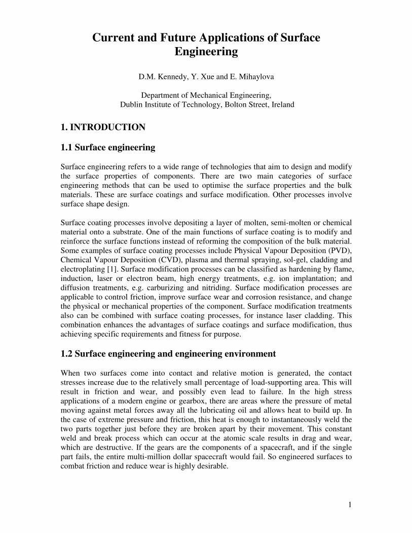
Figure 1. Sea water corrosion
damage of a shaft without coating
Many materials have been developed to have specific bulk properties, although they have not been particularly optimised for the surface properties. Surface engineering can solve these problems by:
i. Implanting alloying atoms to different depths, thereby improving toughness and fatigue properties; (surface modification)
ii. Depositing surface layers, thick or thin, including lubricants; (surface coating) iii. Redesigning the surface shape of the component to distribute stresses.
1.3 Friction, Corrosion and Wear
Surface engineering techniques solve friction, corrosion, and wear problems.
Friction, corrosion and wear are the most common factors that cause engineering failures. In industrialised countries, 7% of GNP represents the cost of friction, wear and corrosion, with the possibility of 1% of this figure being reduced through the use of efficient tribological systems. On a worldwide level, 34% of all lubricants produced are consumed in Europe, with 50% of this being recycled, with a further 2.5 million tonnes being lost in the environment [2].
Corrosion is mainly an electrochemical phenomenon which occurs when metals react with materials in their environment. Figure 1. shows the corrosion damage of a shaft without a proper coating. Corrosion costs in the UK and USA are approximately £30bn and $276bn every year respectively [2-3].
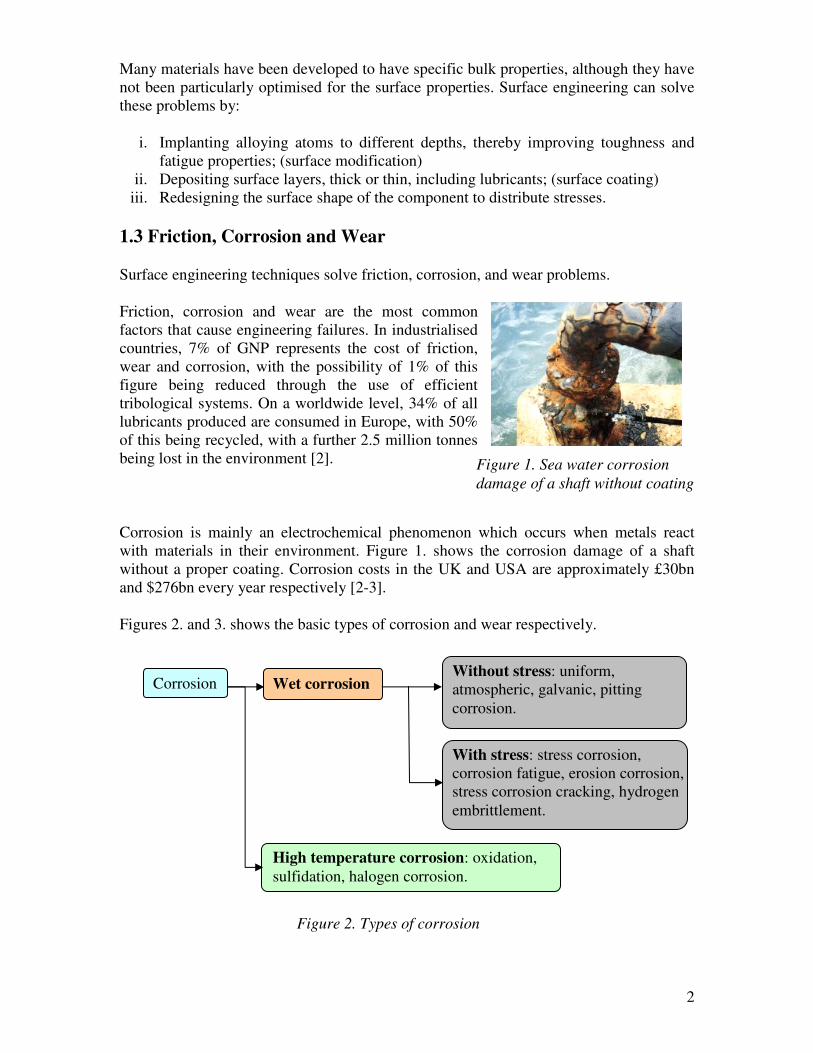
Figures 2. and 3. shows the basic types of corrosion and wear respectively.
Corrosion Wet corrosion
High temperature corrosion: oxidation, sulfidation, halogen corrosion.
Without stress: uniform, atmospheric, galvanic, pitting corrosion.
With stress: stress corrosion, corrosion fatigue, erosion corrosion, stress corrosion cracking, hydrogen embrittlement.
Figure 2. Types of corrosion
3
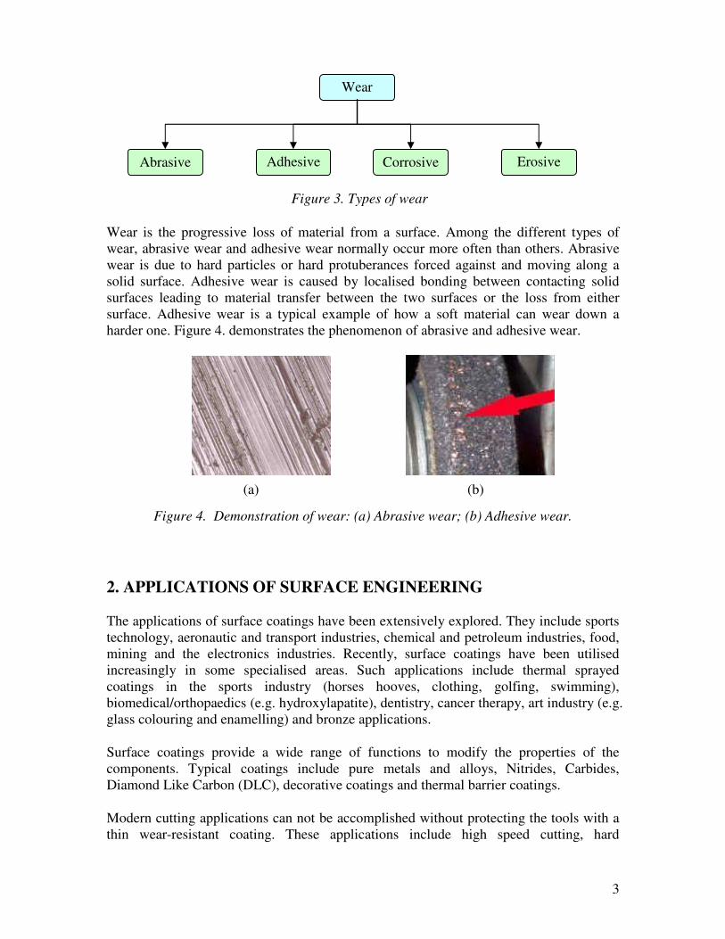
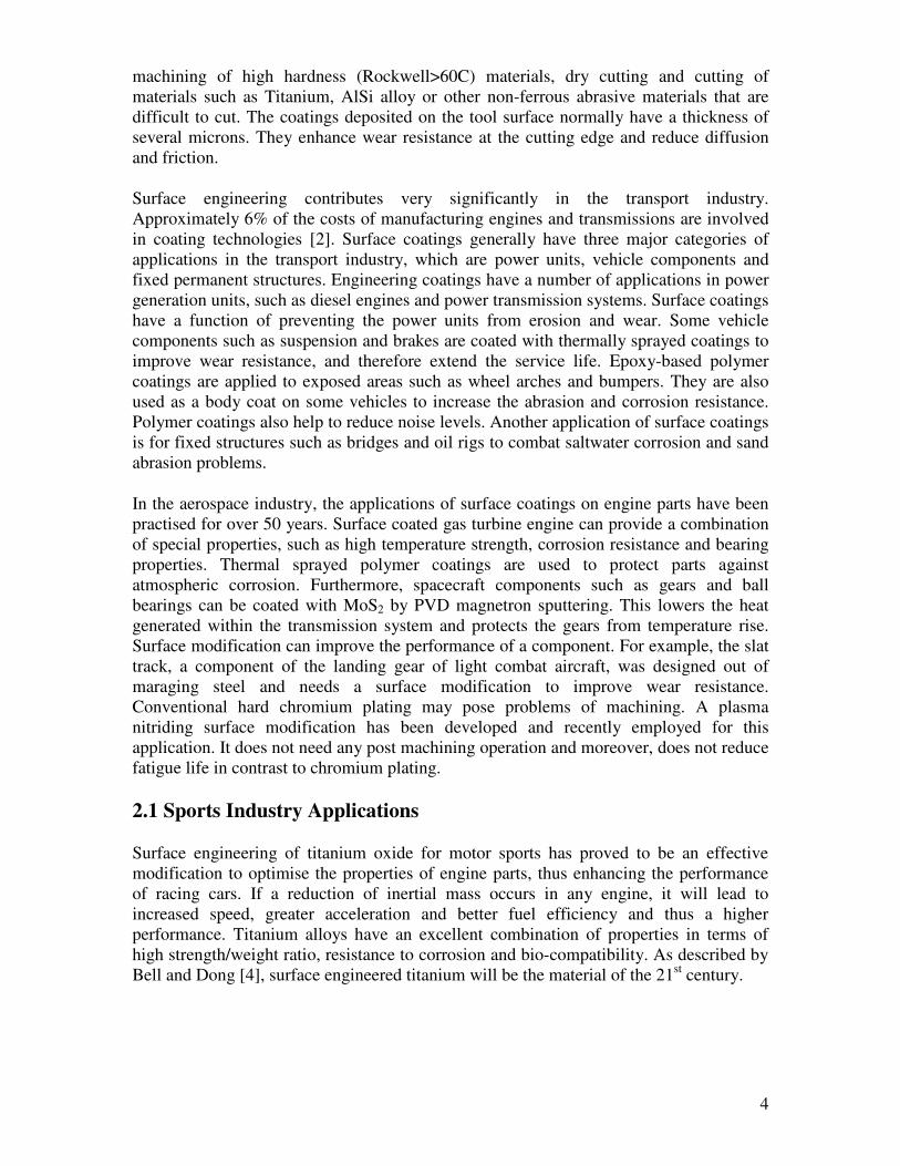
Wear is the progressive loss of material from a surface. Among the different types of wear, abrasive wear and adhesive wear normally occur more often than others. Abrasive wear is due to hard particles or hard protuberances forced against and moving along a solid surface. Adhesive wear is caused by localised bonding between contacting solid surfaces leading to material transfer between the two surfaces or the loss from either surface. Adhesive wear is a typical example of how a soft material can wear down a harder one. Figure 4. demonstrates the phenomenon of abrasive and adhesive wear.
2. APPLICATIONS OF SURFACE ENGINEERING
The applications of surface coatings have been extensively explored. They include sports technology, aeronautic and transport industries, chemical and petroleum industries, food, mining and the electronics industries. Recently, surface coatings have been utilised increasingly in some specialised areas. Such applications include thermal sprayed coatings in the sports industry (horses hooves, clothing, golfing, swimming), biomedical/orthopaedics (e.g. hydroxylapatite), dentistry, cancer therapy, art industry (e.g. glass colouring and enamelling) and bronze applications.
Surface coatings provide a wide range of functions to modify the properties of the components. Typical coatings include pure metals and alloys, Nitrides, Carbides, Diamond Like Carbon (DLC), decorative coatings and thermal barrier coatings.
Modern cutting applications can not be accomplished without protecting the tools with a thin wear-resistant coating. These applications include high speed cutting, hard
Wear
Abrasive Adhesive Corrosive Erosive
Figure 3. Types of wear
(a) (b)
Figure 4. Demonstration of wear: (a) Abrasive wear; (b) Adhesive wear.
4
machining of high hardness (Rockwell>60C) materials, dry cutting and cutting of materials such as Titanium, AlSi alloy or other non-ferrous abrasive materials that are difficult to cut. The coatings deposited on the tool surface normally have a thickness of several microns. They enhance wear resistance at the cutting edge and reduce diffusion and friction.
Surface engineering contributes very significantly in the transport industry. Approximately 6% of the costs of manufacturing engines and transmissions are involved in coating technologies [2]. Surface coatings generally have three major categories of applications in the transport industry, which are power units, vehicle components and fixed permanent structures. Engineering coatings have a number of applications in power generation units, such as diesel engines and power transmission systems. Surface coatings have a function of preventing the power units from erosion and wear. Some vehicle components such as suspension and brakes are coated with thermally sprayed coatings to improve wear resistance, and therefore extend the service life. Epoxy-based polymer coatings are applied to exposed areas such as wheel arches and bumpers. They are also used as a body coat on some vehicles to increase the abrasion and corrosion resistance. Polymer coatings also help to reduce noise levels. Another application of surface coatings is for fixed structures such as bridges and oil rigs to combat saltwater corrosion and sand abrasion problems.
In the aerospace industry, the applications of surface coatings on engine parts have been practised for over 50 years. Surface coated gas turbine engine can provide a combination of special properties, such as high temperature strength, corrosion resistance and bearing properties. Thermal sprayed polymer coatings are used to protect parts against atmospheric corrosion. Furthermore, spacecraft components such as gears and ball bearings can be coated with MoS2 by PVD magnetron sputtering. This lowers the heat generated within the transmission system and protects the gears from temperature rise. Surface modification can improve the performance of a component. For example, the slat track, a component of the landing gear of light combat aircraft, was designed out of maraging steel and needs a surface modification to improve wear resistance. Conventional hard chromium plating may pose problems of machining. A plasma nitriding surface modification has been developed and recently employed for this application. It does not need any post machining operation and moreover, does not reduce fatigue life in contrast to chromium plating.
2.1 Sports Industry Applications
Surface engineering of titanium oxide for motor sports has proved to be an effective modification to optimise the properties of engine parts, thus enhancing the performance of racing cars. If a reduction of inertial mass occurs in any engine, it will lead to increased speed, greater acceleration and better fuel efficiency and thus a higher performance. Titanium alloys have an excellent combination of properties in terms of high strength/weight ratio, resistance to corrosion and bio-compatibility. As described by Bell and Dong [4], surface engineered titanium will be the material of the 21st century.
5
Spin direction
Resistance
Lift
Figure 6. Shot interaction of golf and ball spinning
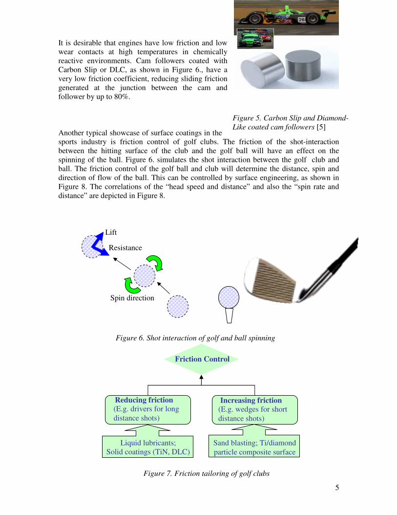
Figure 5. Carbon Slip and Diamond-
Like coated cam followers [5]
It is desirable that engines have low friction and low wear contacts at high temperatures in chemically reactive environments. Cam followers coated with Carbon Slip or DLC, as shown in Figure 6., have a very low friction coefficient, reducing sliding friction generated at the junction between the cam and follower by up to 80%.
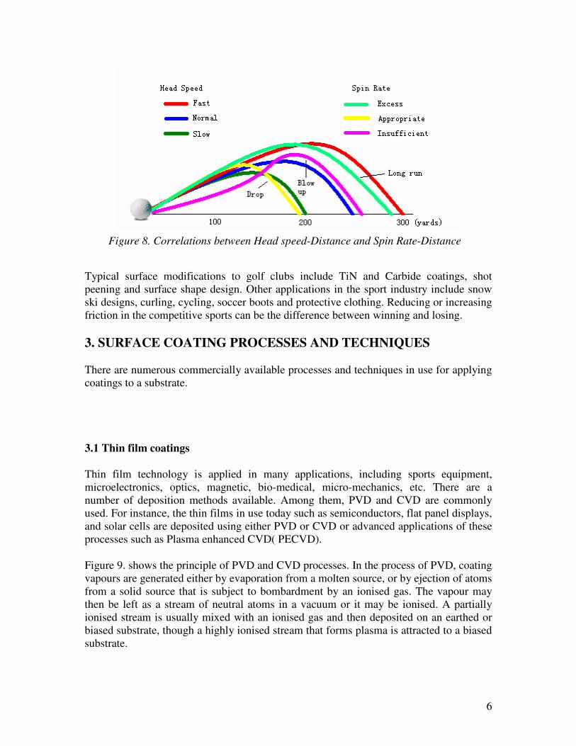
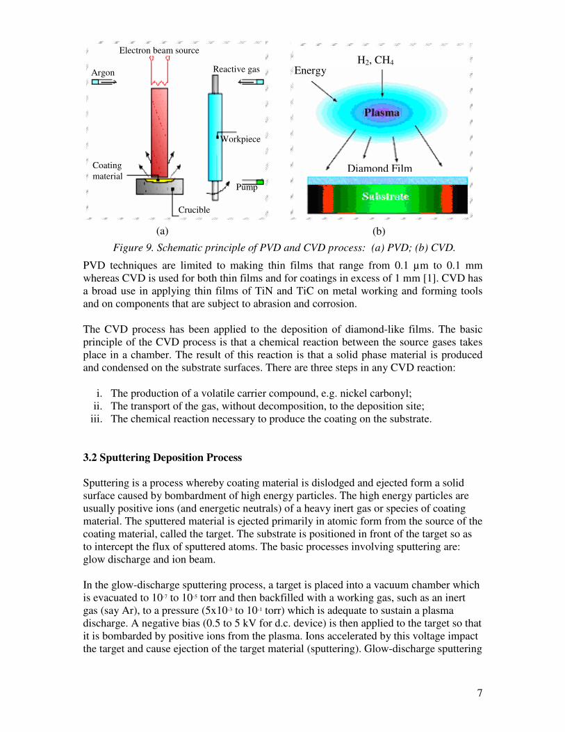
Another typical showcase of surface coatings in the sports industry is friction control of golf clubs. The friction of the shot-interaction between the hitting surface of the club and the golf ball will have an effect on the spinning of the ball. Figure 6. simulates the shot interaction between the golf club and ball. The friction control of the golf ball and club will determine the distance, spin and direction of flow of the ball. This can be controlled by surface engineering, as shown in Figure 8. The correlations of the “head speed and distance” and also the “spin rate and distance” are depicted in Figure 8.
Friction Control
Liquid lubricants; Solid coatings (TiN, DLC)
Reducing friction
(E.g. drivers for long distance shots)
Increasing friction
(E.g. wedges for short distance shots)
Sand blasting; Ti/diamond particle composite surface
Figure 7. Friction tailoring of golf clubs
6
Typical surface modifications to golf clubs include TiN and Carbide coatings, shot peening and surface shape design. Other applications in the sport industry include snow ski designs, curling, cycling, soccer boots and protective clothing. Reducing or increasing friction in the competitive sports can be the difference between winning and losing.
3. SURFACE COATING PROCESSES AND TECHNIQUES
There are numerous commercially available processes and techniques in use for applying coatings to a substrate.
3.1 Thin film coatings
Thin film technology is applied in many applications, including sports equipment, microelectronics, optics, magnetic, bio-medical, micro-mechanics, etc. There are a number of deposition methods available. Among them, PVD and CVD are commonly used. For instance, the thin films in use today such as semiconductors, flat panel displays, and solar cells are deposited using either PVD or CVD or advanced applications of these processes such as Plasma enhanced CVD( PECVD).
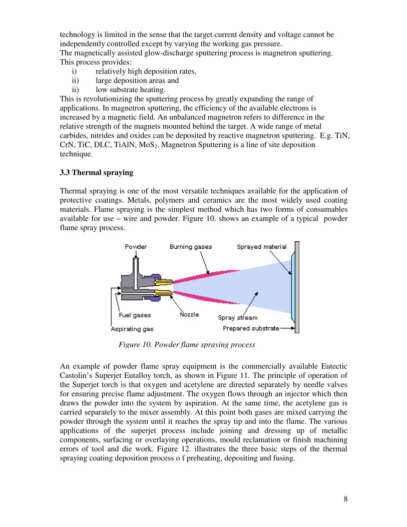
Figure 9. shows the principle of PVD and CVD processes. In the process of PVD, coating vapours are generated either by evaporation from a molten source, or by ejection of atoms from a solid source that is subject to bombardment by an ionised gas. The vapour may then be left as a stream of neutral atoms in a vacuum or it may be ionised. A partially ionised stream is usually mixed with an ionised gas and then deposited on an earthed or biased substrate, though a highly ionised stream that forms plasma is attracted to a biased substrate.
Figure 8. Correlations between Head speed-Distance and Spin Rate-Distance
7
PVD techniques are limited to making thin films that range from 0.1 µm to 0.1 mm whereas CVD is used for both thin films and for coatings in excess of 1 mm [1]. CVD has a broad use in applying thin films of TiN and TiC on metal working and forming tools and on components that are subject to abrasion and corrosion.
The CVD process has been applied to the deposition of diamond-like films. The basic principle of the CVD process is that a chemical reaction between the source gases takes place in a chamber. The result of this reaction is that a solid phase material is produced and condensed on the substrate surfaces. There are three steps in any CVD reaction:
i. The production of a volatile carrier compound, e.g. nickel carbonyl; ii. The transport of the gas, without decomposition, to the deposition site;
iii. The chemical reaction necessary to produce the coating on the substrate.
3.2 Sputtering Deposition Process Sputtering is a process whereby coating material is dislodged and ejected form a solid surface caused by bombardment of high energy particles. The high energy particles are usually positive ions (and energetic neutrals) of a heavy inert gas or species of coating material. The sputtered material is ejected primarily in atomic form from the source of the coating material, called the target. The substrate is positioned in front of the target so as to intercept the flux of sputtered atoms. The basic processes involving sputtering are: glow discharge and ion beam. In the glow-discharge sputtering process, a target is placed into a vacuum chamber which is evacuated to 10-7 to 10-5 torr and then backfilled with a working gas, such as an inert gas (say Ar), to a pressure (5x10⁻³ to 10-1 torr) which is adequate to sustain a plasma discharge. A negative bias (0.5 to 5 kV for d.c. device) is then applied to the target so that it is bombarded by positive ions from the plasma. Ions accelerated by this voltage impact the target and cause ejection of the target material (sputtering). Glow-discharge sputtering
Figure 9. Schematic principle of PVD and CVD process: (a) PVD; (b) CVD.
(a) (b)
Electron beam source
Argon
Coating material
Crucible
Reactive gas
Workpiece
Pump
H2, CH4
Energy
Diamond Film
8
technology is limited in the sense that the target current density and voltage cannot be independently controlled except by varying the working gas pressure. The magnetically assisted glow-discharge sputtering process is magnetron sputtering. This process provides:
i) relatively high deposition rates, ii) large deposition areas and ii) low substrate heating.
This is revolutionizing the sputtering process by greatly expanding the range of applications. In magnetron sputtering, the efficiency of the available electrons is increased by a magnetic field. An unbalanced magnetron refers to difference in the relative strength of the magnets mounted behind the target. A wide range of metal carbides, nitrides and oxides can be deposited by reactive magnetron sputtering. E.g. TiN, CrN, TiC, DLC, TiAlN, MoS2. Magnetron Sputtering is a line of site deposition technique.
3.3 Thermal spraying
Thermal spraying is one of the most versatile techniques available for the application of protective coatings. Metals, polymers and ceramics are the most widely used coating materials. Flame spraying is the simplest method which has two forms of consumables available for use – wire and powder. Figure 10. shows an example of a typical powder flame spray process.
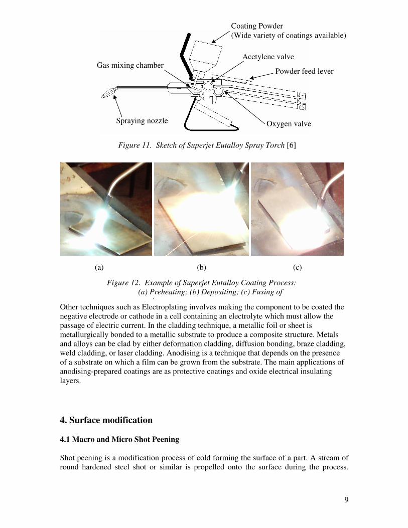
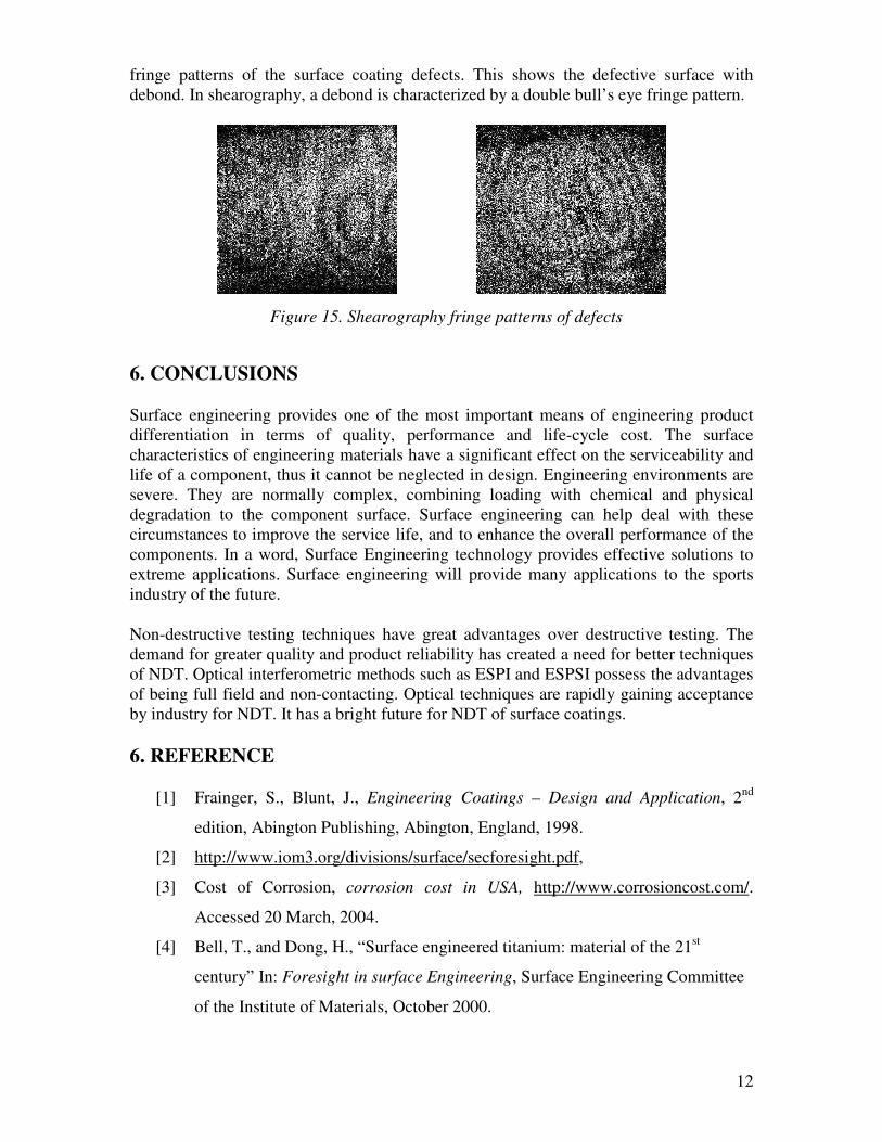
An example of powder flame spray equipment is the commercially available Eutectic Castolin’s Superjet Eutalloy torch, as shown in Figure 11. The principle of operation of the Superjet torch is that oxygen and acetylene are directed separately by needle valves for ensuring precise flame adjustment. The oxygen flows through an injector which then draws the powder into the system by aspiration. At the same time, the acetylene gas is carried separately to the mixer assembly. At this point both gases are mixed carrying the powder through the system until it reaches the spray tip and into the flame. The various applications of the superjet process include joining and dressing up of metallic components, surfacing or overlaying operations, mould reclamation or finish machining errors of tool and die work. Figure 12. illustrates the three basic steps of the thermal spraying coating deposition process o f preheating, depositing and fusing.
Figure 10. Powder flame spraying process
9
Other techniques such as Electroplating involves making the component to be coated the negative electrode or cathode in a cell containing an electrolyte which must allow the passage of electric current. In the cladding technique, a metallic foil or sheet is metallurgically bonded to a metallic substrate to produce a composite structure. Metals and alloys can be clad by either deformation cladding, diffusion bonding, braze cladding, weld cladding, or laser cladding. Anodising is a technique that depends on the presence of a substrate on which a film can be grown from the substrate. The main applications of anodising-prepared coatings are as protective coatings and oxide electrical insulating layers.
4. Surface modification
4.1 Macro and Micro Shot Peening
Shot peening is a modification process of cold forming the surface of a part. A stream of round hardened steel shot or similar is propelled onto the surface during the process.
Coating Powder (Wide variety of coatings available)
Acetylene valve
Oxygen valve Spraying nozzle
Gas mixing chamber Powder feed lever
Figure 11. Sketch of Superjet Eutalloy Spray Torch [6]
(a) (b) (c)
Figure 12. Example of Superjet Eutalloy Coating Process:
(a) Preheating; (b) Depositing; (c) Fusing of
coating

10
Figure 13. shows the general process of shot peening. Shot peening process is non-abrasive and improves the fatigue properties of the part by the introduction of compression stresses in the surface layer. The presence of this surface compressive stress serves to retard the initiation and growth of fatigue cracks. Shot peening can be conducted on a macro or micro scale, depending on the components and applications. Shot size in the order of 10mm diameter is used in large operations such as on Airbus wheels and micro shot in the order 4 to 50 micron diameter can be used to improve the properties of thin films on components. By using shot peening, the service life of springs can increase by 400% to 1200%, depending on the extent of peening already imparted on the spring. Shot peening processes can also increase the fatigue life of gears by over 500%. Other parts that are usually shot peened include axles, torsion bars, marine propellers, rudders, and exhaust megaphones. All have benefited from increased fatigue life, or an increase in service loads.
4.2 Ion Implantation
Ion implantation is a surface modification process in which ions are injected into the surface region of a substrate. These processes can improve substrate material properties of hardness, wear resistance, corrosion resistance and fatigue, thus improving the product’s service life. Furthermore, it is a potential enhancement method for plating processes, such as chrome plating. High-energy ions, typically 10–200 keV in energy, are produced in an accelerator and directed as a beam onto the surface of the substrate. The order of magnitude of the kinetic energies which were produced by the ions impingement on the substrate is more than 4 times greater than the binding energy of formation of the solid substrate with the surface upon impact. Virtually, any element can be injected into the near-surface region of any solid substrate. The modern method of implantation is plasma source ion implantation. This form of ion implantation involves using plasma as a source which was excited from a gas typically through the use of an RF antenna. Ion implantation processes commonly have products like nitrides, borides and carbides, etc.
5. METHODS OF TESTING SURFACE COATINGS
Surface testing is a substantial procedure for quality assurance of surface engineering products. There are many types of testing methods which are applicable to surface
Shot Peening
Nozzle
Shot
Test Piece
Figure 13. Demonstration of Shot Peening Process
Shot
Compressive Stresses

11
coating inspections. They are generally categorised as destructive and non-destructive and as the titles suggest, Destructive tests are carried out to the specimen’s failure, and Non-Destructive Testing (NDT) is applied without damaging the component. Destructive testing on a small percentage of a component surface is acceptable, where large numbers of similar articles are being processed. Typical destructive tests applicable to surface coating include bend testing, adhesion/abrasion testing, chemical analysis, porosity measurement and hardness testing, etc. Various types and sizes of defects may be introduced to a coating during the coating process. The nature and size of the defect may influence the subsequent performance of the coated component. The main NDT systems for defect detection include eddy current, liquid penetrant inspection, radiography, ultrasonic and optical technique, etc [7]. Eddy current technique can be used to detect surface and sub-surface defects within components, determine the thickness of non-conductive surface coatings, provide information about structural features, and measure physical properties. Ultrasonic techniques are commonly used as a NDT techniques for detection of internal defects in materials and small surface cracks. It is used for the routine inspection of aircraft and road and rail vehicles and tracks in the search for incipient fatigue cracks. Ultrasonic testing is an indispensable tool for quality control and quality assurance as the equipment is extremely portable, relatively inexpensive and versatile. Recently, optical techniques have gained a greater level of recognition in industrial applications. For example, Electronic Speckle Pattern Shearing Interferometry (ESPSI), also called shearography, has become the most popular defect detection method because of its attractive characteristics [8, 9]. Shearography is full-field, non-contacting and it does not require fluid coupling. Also shearography is less sensitive than Electronic Speckle Pattern Interferometry (ESPI) and faster than ultrasonic testing, which is the main advantage over these two techniques. Shearography has already been accepted by the rubber industry for NDT of tyres, and been used by the aerospace industry for evaluating composites [10]. Figure 14. shows the schematic set-up of a commonly used shearography system.
Z
P(x,y)
X
Computer
Frame grabber
Shearing device
CCD camera
Laser beam
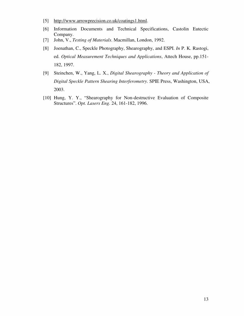
Shearography reveals flaws by looking for flaw-induced strain anomalies which are translated into irregularity in the fringe pattern. Figure 15. illustrates the shearography
Figure 14. Schematic diagram of a shearography system
12
fringe patterns of the surface coating defects. This shows the defective surface with debond. In shearography, a debond is characterized by a double bull’s eye fringe pattern.
6. CONCLUSIONS
Surface engineering provides one of the most important means of engineering product differentiation in terms of quality, performance and life-cycle cost. The surface characteristics of engineering materials have a significant effect on the serviceability and life of a component, thus it cannot be neglected in design. Engineering environments are severe. They are normally complex, combining loading with chemical and physical degradation to the component surface. Surface engineering can help deal with these circumstances to improve the service life, and to enhance the overall performance of the components. In a word, Surface Engineering technology provides effective solutions to extreme applications. Surface engineering will provide many applications to the sports industry of the future.
Non-destructive testing techniques have great advantages over destructive testing. The demand for greater quality and product reliability has created a need for better techniques of NDT. Optical interferometric methods such as ESPI and ESPSI possess the advantages of being full field and non-contacting. Optical techniques are rapidly gaining acceptance by industry for NDT. It has a bright future for NDT of surface coatings.
6. REFERENCE
[1] Frainger, S., Blunt, J., Engineering Coatings – Design and Application, 2nd
edition, Abington Publishing, Abington, England, 1998.
[2] http://www.iom3.org/divisions/surface/secforesight.pdf,
[3] Cost of Corrosion, corrosion cost in USA, http://www.corrosioncost.com/.
Accessed 20 March, 2004.
[4] Bell, T., and Dong, H., “Surface engineered titanium: material of the 21st
century” In: Foresight in surface Engineering, Surface Engineering Committee
of the Institute of Materials, October 2000.
Figure 15. Shearography fringe patterns of defects
13
[5] http://www.arrowprecision.co.uk/coatings1.html.
[6] Information Documents and Technical Specifications, Castolin Eutectic Company.
[7] John, V., Testing of Materials. Macmillan, London, 1992.
[8] Joenathan, C., Speckle Photography, Shearography, and ESPI. In P. K. Rastogi,
ed. Optical Measurement Techniques and Applications, Attech House, pp.151-
182, 1997.
[9] Steinchen, W., Yang, L. X., Digital Shearography - Theory and Application of
Digital Speckle Pattern Shearing Interferometry. SPIE Press, Washington, USA,
2003.
[10] Hung, Y. Y., “Shearography for Non-destructive Evaluation of Composite Structures”. Opt. Lasers Eng. 24, 161-182, 1996.