Cummins Power Generation 10kWe SOFC Power System ... Library/Events/2003/seca/Daniel... ·...
51
April 15, 2003 SECA Annual Workshop 1 EFS Holdings, LLC Solid Oxide Fuel Cells and Fuel Processors SECA Annual Workshop Cummins Power Generation 10kWe SOFC Power System Commercialization Program April 15, 2003 Seattle, Washington Dan Norrick -- CPG This presentation highlights the efforts and achievement of the CPG-SOFCo team over the course of our first year of Phase 1 of the SECA program.
Transcript of Cummins Power Generation 10kWe SOFC Power System ... Library/Events/2003/seca/Daniel... ·...

1
April 15, 2003 SECA Annual Workshop 1
EFS Holdings, LLC
Solid Oxide Fuel Cellsand Fuel Processors
SECA Annual Workshop
Cummins Power Generation10kWe SOFC Power System
Commercialization Program
April 15, 2003Seattle, Washington
Dan Norrick -- CPG
This presentation highlights the efforts and achievement of the CPG-SOFCoteam over the course of our first year of Phase 1 of the SECA program.
2
April 15, 2003 SECA Annual Workshop 2
EFS Holdings, LLC
Solid Oxide Fuel Cellsand Fuel Processors
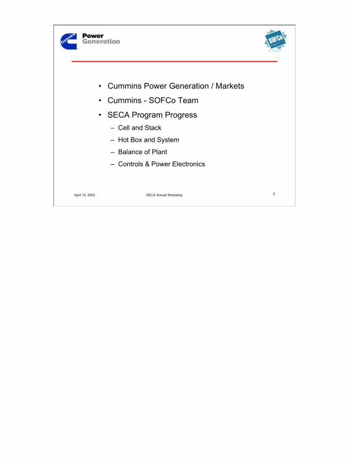
• Cummins Power Generation / Markets
• Cummins - SOFCo Team
• SECA Program Progress– Cell and Stack
– Hot Box and System
– Balance of Plant
– Controls & Power Electronics
3
April 15, 2003 SECA Annual Workshop 3
EFS Holdings, LLC
Solid Oxide Fuel Cellsand Fuel Processors
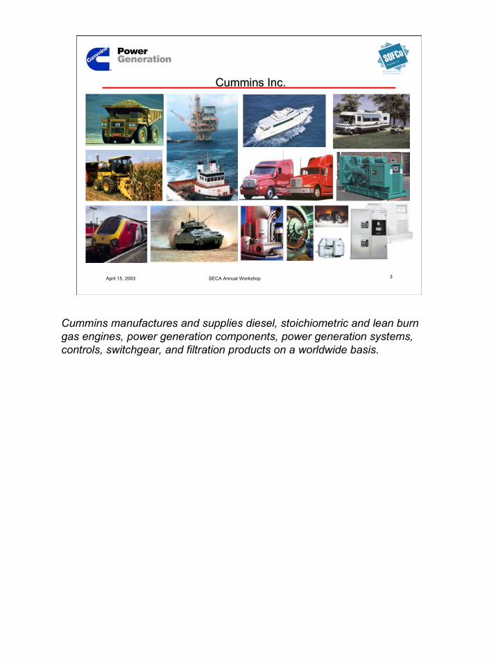
Cummins Inc.Cummins Inc.
Cummins manufactures and supplies diesel, stoichiometric and lean burngas engines, power generation components, power generation systems,controls, switchgear, and filtration products on a worldwide basis.

4
April 15, 2003 SECA Annual Workshop 4
EFS Holdings, LLC
Solid Oxide Fuel Cellsand Fuel Processors
Cummins Power GenerationWorld Headquarters and Manufacturing
Cummins Power Generation worldwide headquarters is in Minneapolis, MN.Our SECA partner, SOFCo, is headquartered in Alliance, OH.

5
April 15, 2003 SECA Annual Workshop 5
EFS Holdings, LLC
Solid Oxide Fuel Cellsand Fuel Processors
Cummins Power Generation
Variable SpeedGensets
Micro-TurbineGensets
Controls,PowerElectronics,Switches,Switchgear
Diesel and Gas EngineGensets, CHP Systems
Diesel, LeanBurn andStoichiometricGas Engines
Noise AttenuatedGensets
A technology-neutralworldwide developerand manufacturer of
power generationequipment ...
Cummins Power Generation designs, develops, manufactures, distributes,and services a wide range of power generation solutions on a worldwidebasis.By virtue of our participation in existing power generation markets, CPG is inan advantageous position to understand the requirements of a broad rangeof customer needs and the relevant attributes of technologies available tomeet those needs.CPG considers the SOFC a prime candidate to meet customer needs in keymarkets and, as technology matures, to gradually assume a significant shareof the power generation market. Key attributes will vary by market, and thesuccess of the SOFC will be determined by competitive market forces.

6
April 15, 2003 SECA Annual Workshop 6
EFS Holdings, LLC
Solid Oxide Fuel Cellsand Fuel Processors
Stationary Power Markets
Telecommunications
GenSet
SECA Program Entry Markets
Recreational Vehicle
CommercialMobile
Entry markets will be driven by low noise and vibration, high reliability, lowmaintenance.
7
April 15, 2003 SECA Annual Workshop 7
EFS Holdings, LLC
Solid Oxide Fuel Cellsand Fuel Processors
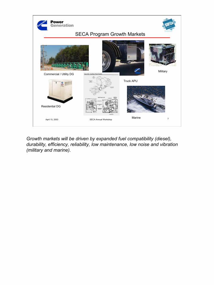
Stationary Power Markets
Residential DG
Commercial / Utility DG
SECA Program Growth Markets
Marine
Military
Truck APU
Growth markets will be driven by expanded fuel compatibility (diesel),durability, efficiency, reliability, low maintenance, low noise and vibration(military and marine).

8
April 15, 2003 SECA Annual Workshop 8
EFS Holdings, LLC
Solid Oxide Fuel Cellsand Fuel Processors
0%
10%
20%
30%
40%
50%
60%
0%-25% 25% - 50% 50%-75% 75%-100%
Load Bands
% O
pera
ting
Tim
e
Application Data
0%
5%
10%
15%
20%
25%
2-30 min 30-120 min 120-240 min ">240 Min
Duration of Operation
% o
f Sta
rts
• Historical operating data exists for target markets
• System architecture is designed to meet or exceed customer expectations
CPG has data on many applications derived from production control datalogging features. Actual field applications typically indicate importance ofpart load efficiency.

9
April 15, 2003 SECA Annual Workshop 9
EFS Holdings, LLC
Solid Oxide Fuel Cellsand Fuel Processors
Cummins Power Generation
• Significant market share in target markets
• Existing market presence in both stationaryand mobile applications from 2kW to 2.5MW

10
April 15, 2003 SECA Annual Workshop 10
EFS Holdings, LLC
Solid Oxide Fuel Cellsand Fuel Processors
CPG – SOFCo Team
• Electronic controls• Power electronics • Fuel systems• Air handling systems• Noise and vibration• System integration• Manufacturing• Marketing, sales, distribution
• Planar SOFC technology• Reformer technology• Material science• Heat transfer• Computational fluid dynamics• Numerical modeling• Multilayer ceramic manufacturing
Clean energy for the world
The portfolio of capabilities needed to successfullycommercialize the SOFC.

11
April 15, 2003 SECA Annual Workshop 11
EFS Holdings, LLC
Solid Oxide Fuel Cellsand Fuel Processors
Organizational transition
• McDermott Technology, Inc (MTI)– Technology center for McDermott / Babcock & Wilcox– SOFCo– Hydrogen systems (fuel processor development)
Program Staff now dedicated entirely to fuel cellsand fuel processing as…
• SOFCo-EFS Holdings LLC– Exclusive commitment to fuel cells and fuel processing– Aligned with SECA– Backed by McDermott (BWX Technologies)
12
April 15, 2003 SECA Annual Workshop 12
EFS Holdings, LLC
Solid Oxide Fuel Cellsand Fuel Processors
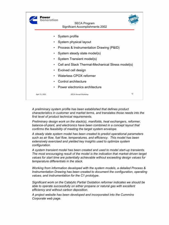
SECA ProgramSignificant Accomplishments 2002
• System profile
• System physical layout
• Process & Instrumentation Drawing (P&ID)
• System steady state model(s)
• System Transient model(s)
• Cell and Stack Thermal-Mechanical Stress model(s)
• Evolved cell design
• Waterless CPOX reformer
• Control architecture
• Power electronics architecture
A preliminary system profile has been established that defines productcharacteristics in customer and market terms, and translates those needs into thefirst level of product technical requirements.Preliminary design work on the stack(s), manifolds, heat exchangers, reformer,balance-of-plant, and electronics have been combined in a concept layout thatconfirms the feasibility of meeting the target system envelope.A steady state system model has been created to predict operational parameterssuch as air flow, fuel flow, temperatures, and efficiency. This model has beenextensively exercised and yielded key insights used to optimize systemconfiguration.A system transient model has been created and used to model start-up transients.The most encouraging result of the model is the indication that market-driven targetvalues for start time are potentially achievable without exceeding design values fortemperature differentials in the stack.
Working from information developed with the system models, a detailed Process &Instrumentation Drawing has been created to document the configuration, operatingvalues, and instrumentation for the C1 prototype.
Significant work on the Catalytic Partial Oxidation reformer indicates we should beable to operate successfully on either propane or natural gas with excellentefficiency and without carbon deposition.A project website has been developed and incorporated into the CumminsCorporate web page.
13
April 15, 2003 SECA Annual Workshop 13
EFS Holdings, LLC
Solid Oxide Fuel Cellsand Fuel Processors
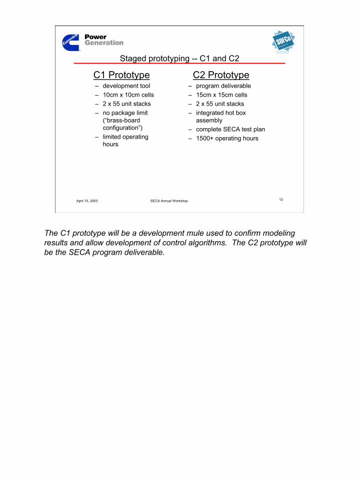
Staged prototyping -- C1 and C2
C1 Prototype– development tool– 10cm x 10cm cells– 2 x 55 unit stacks– no package limit
(“brass-boardconfiguration”)
– limited operatinghours
C2 Prototype– program deliverable– 15cm x 15cm cells– 2 x 55 unit stacks– integrated hot box
assembly– complete SECA test plan– 1500+ operating hours
The C1 prototype will be a development mule used to confirm modelingresults and allow development of control algorithms. The C2 prototype willbe the SECA program deliverable.
14
April 15, 2003 SECA Annual Workshop 14
EFS Holdings, LLC
Solid Oxide Fuel Cellsand Fuel Processors
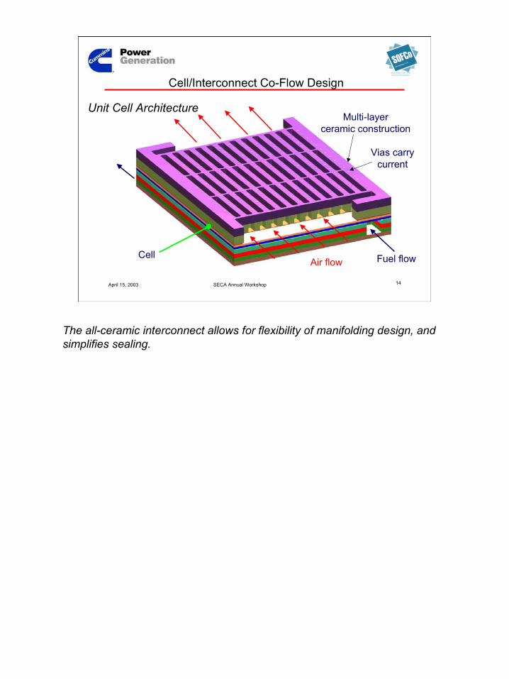
Air flow Fuel flowCell
Multi-layerceramic construction
Vias carrycurrent
Cell/Interconnect Co-Flow Design
Unit Cell Architecture
The all-ceramic interconnect allows for flexibility of manifolding design, andsimplifies sealing.
15
April 15, 2003 SECA Annual Workshop 15
EFS Holdings, LLC
Solid Oxide Fuel Cellsand Fuel Processors
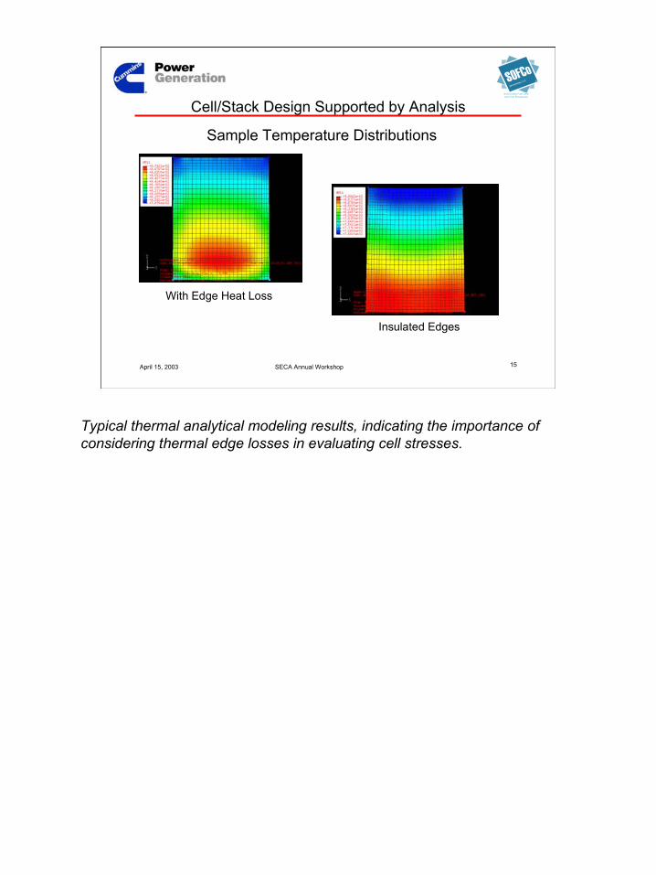
Cell/Stack Design Supported by Analysis
Sample Temperature Distributions
With Edge Heat Loss
Insulated Edges
Typical thermal analytical modeling results, indicating the importance ofconsidering thermal edge losses in evaluating cell stresses.

16
April 15, 2003 SECA Annual Workshop 16
EFS Holdings, LLC
Solid Oxide Fuel Cellsand Fuel Processors
In-Plane Current and Voltage Distributions
Cell/Stack Design Supported by Analysis …
Anode Potential DistributionFringes 0.004 to 0.02V
VoltCathode Potential DistributionFringes 0.26 to 0.28V
VoltageVolt
Note that the Anode illustration is rotated 90 deg from the Cathode. Dotsare current carrying vias. Illustrating in-plane current effects.

17
April 15, 2003 SECA Annual Workshop 17
EFS Holdings, LLC
Solid Oxide Fuel Cellsand Fuel Processors
FEA Stress Analysis (ABAQUS)
Temperature distributionfrom operation, transients,hot standby, etc. Calculatedand confirmed with selectedmeasurement points fromoperating stack.
Stress state across the rangeof system operation. Usestress level and duration foreach condition to determinecumulative probability offailure at each element.
Plus residual stresses,layer CTEs, stack loads,boundary conditions, etc.
Temperature Stress

18
April 15, 2003 SECA Annual Workshop 18
EFS Holdings, LLC
Solid Oxide Fuel Cellsand Fuel Processors
Typical Cell/Stack Mechanical Analysis Process
PSOFCStack
Design
Structural Details (e.g. layers, holes, vias)
Loads (e.g. CTE mismatch, constraints, thermal)Finite ElementAnalysis Using
Global, Layered,& Detailed Models
MaterialProperties(e.g. �, E, �)
Predicted StressState ThroughoutVolume of Materialfor Each Operating
Condition
Probability ofFailure Prediction
(By Region)
Mechanical Tests OnEach Material In
Stack
(As-Manufactured)CharacteristicStrength (�o)
WeibullModulus (m)
TensileStresses
Evaluate for Various FailureModes
(e.g. Fast Fracture, Slow CrackGrowth, Material Degradation,
Fatigue, Creep)
Design Feedback
Calculate orMeasure
TemperatureDistributions
for EachOperatingCondition
Measure “As-Manufactured” State
(e.g. Flatness,Residual Stresses)
Operation (e.g. Steady-State, Transients, Standby)
19
April 15, 2003 SECA Annual Workshop 19
EFS Holdings, LLC
Solid Oxide Fuel Cellsand Fuel Processors
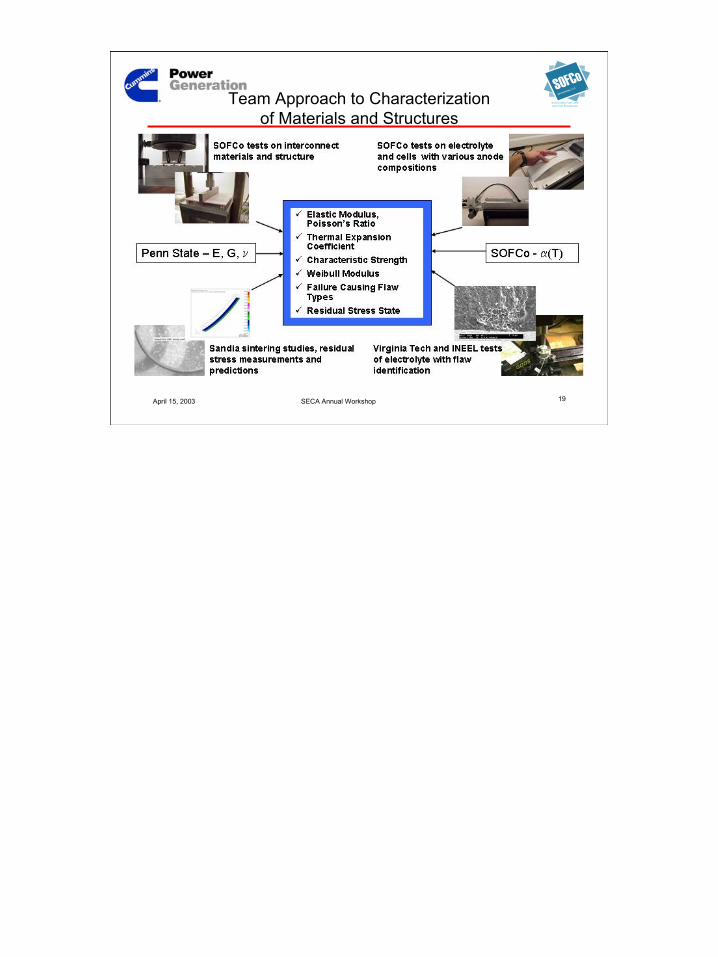
Team Approach to Characterizationof Materials and Structures
20
April 15, 2003 SECA Annual Workshop 20
EFS Holdings, LLC
Solid Oxide Fuel Cellsand Fuel Processors
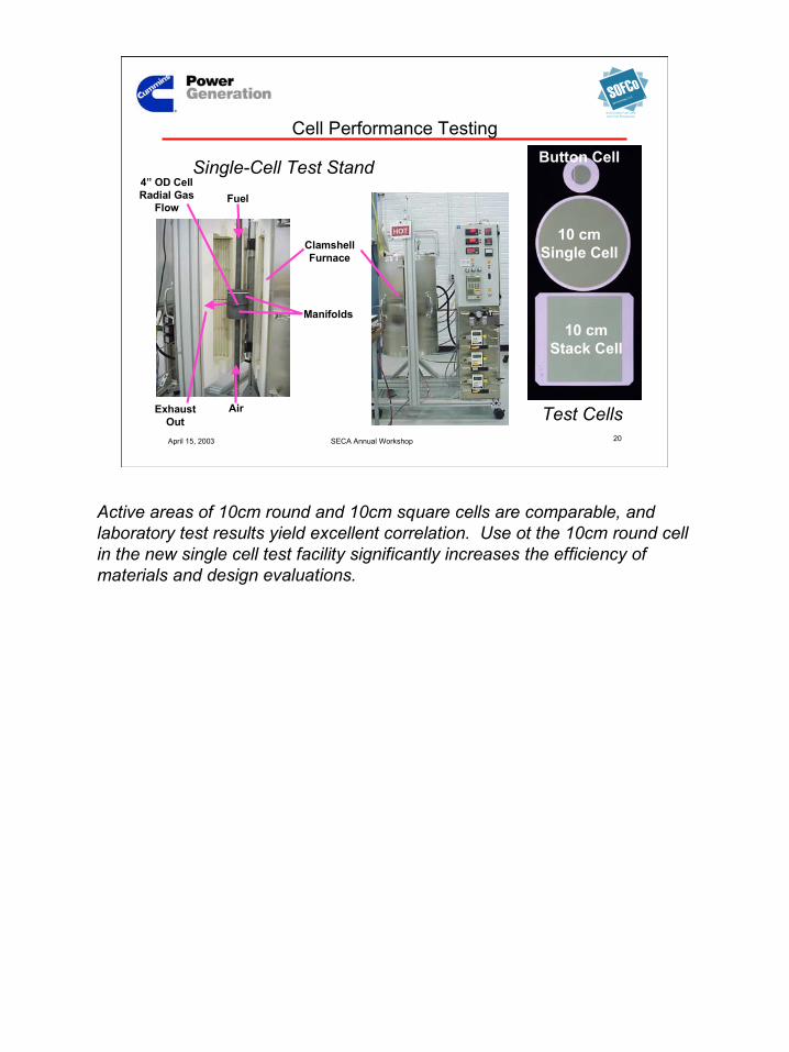
Cell Performance Testing
4” OD CellRadial Gas
Flow
ClamshellFurnace
Manifolds
Fuel
AirExhaustOut
Button Cell
10 cmSingle Cell
10 cmStack Cell
Single-Cell Test Stand
Test Cells
Active areas of 10cm round and 10cm square cells are comparable, andlaboratory test results yield excellent correlation. Use ot the 10cm round cellin the new single cell test facility significantly increases the efficiency ofmaterials and design evaluations.
21
April 15, 2003 SECA Annual Workshop 21
EFS Holdings, LLC
Solid Oxide Fuel Cellsand Fuel Processors
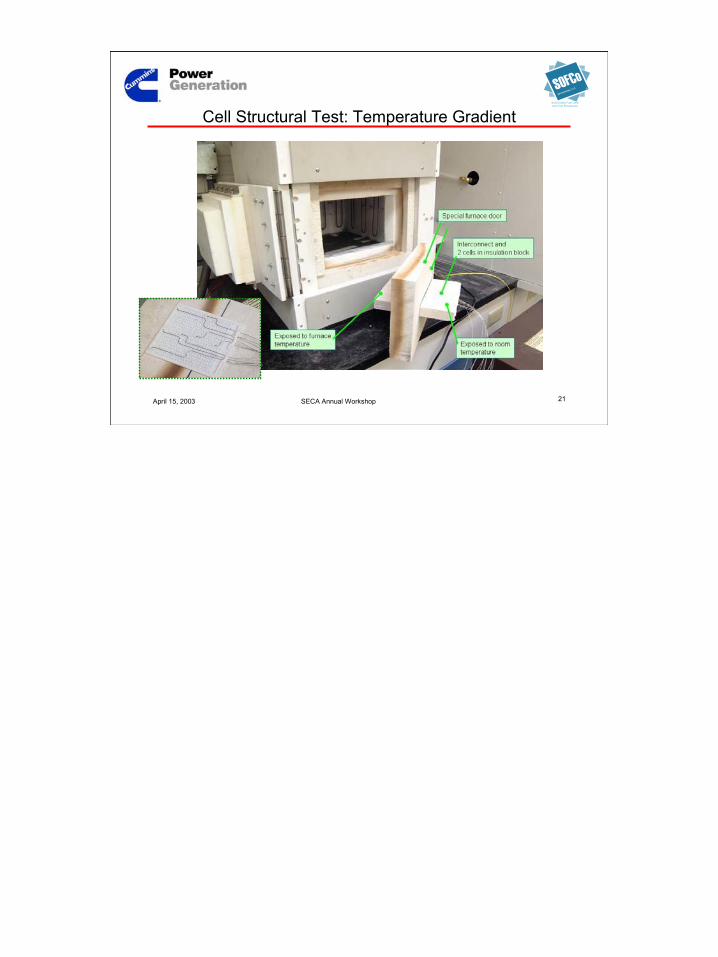
Cell Structural Test: Temperature Gradient
22
April 15, 2003 SECA Annual Workshop 22
EFS Holdings, LLC
Solid Oxide Fuel Cellsand Fuel Processors
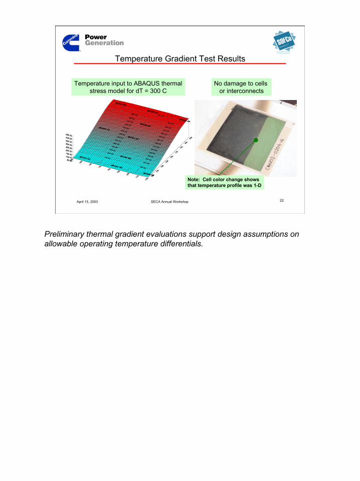
Temperature Gradient Test Results
Temperature input to ABAQUS thermalstress model for dT = 300 C
No damage to cells or interconnects
Note: Cell color change showsthat temperature profile was 1-D
Preliminary thermal gradient evaluations support design assumptions onallowable operating temperature differentials.

23
April 15, 2003 SECA Annual Workshop 23
EFS Holdings, LLC
Solid Oxide Fuel Cellsand Fuel Processors
Cell and Stack Development Status• Cell breakage slowed stack
development in 2002• Several cell designs evaluated to
find a design rugged enough forstack tests
– Baseline co-fired– Thin anode– Patterned anode– Graded anode– 3Y electrolyte– Various electrolyte thicknesses
• SOFCo post-fired cell and 3rd
party cells are supporting 2003stack development while SOFConext-generation cell developmentprogresses
Co-fired cellwith microcrack penetration into electrolyte
Post-fired cell with nomicrocrack penetration intoelectrolyte
Parallel path approach provides robust post-fired cells for ongoing stack andPCU development, parallel development of co-fired cells for optimalperformance.

24
April 15, 2003 SECA Annual Workshop 24
EFS Holdings, LLC
Solid Oxide Fuel Cellsand Fuel Processors
Power Cell Unit (PCU) Development
Turn this …
Today’s laboratorytest technology
Tomorrow’sreal-world product
… Into this

25
April 15, 2003 SECA Annual Workshop 25
EFS Holdings, LLC
Solid Oxide Fuel Cellsand Fuel Processors
Interconnect Scale-Up
• Scale-up to achieveSECA cost goals
• Scale-up feasibilitydemonstrated in 2002
• Demonstrate earlyprototype componentsby year-end
Fired 20 x 20 cm Proof-of-Concept Part

26
April 15, 2003 SECA Annual Workshop 26
EFS Holdings, LLC
Solid Oxide Fuel Cellsand Fuel Processors
SOFC Cell and Stack Progress
Cell/Stack Performance• 40% reduction in ASR (cells and stacks)
– Recent cell tests demonstrate ASR < 0.5 ohm-cm2
• Implemented 2nd generation stack design– Integral gas distribution allows co-flow architecture– Improved performance
• High fuel utilization demonstrated– >85% for 10 cm single cells– >70% for 5-cell stacks
27
April 15, 2003 SECA Annual Workshop 27
EFS Holdings, LLC
Solid Oxide Fuel Cellsand Fuel Processors
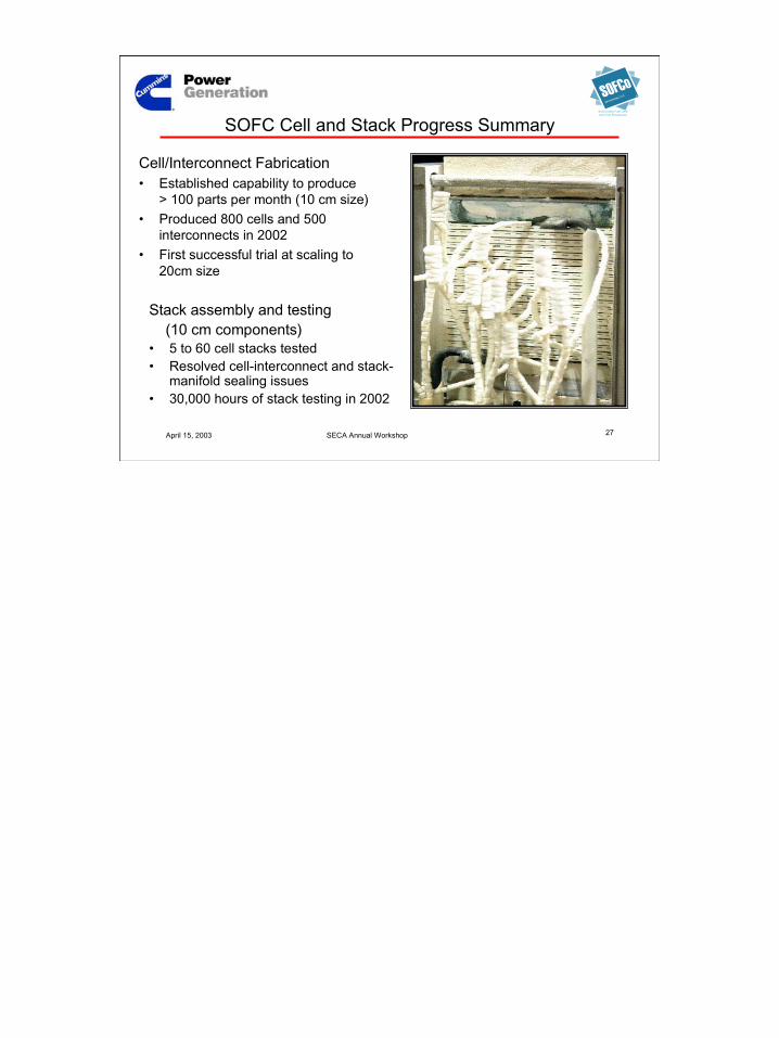
SOFC Cell and Stack Progress Summary
Cell/Interconnect Fabrication• Established capability to produce
> 100 parts per month (10 cm size)• Produced 800 cells and 500
interconnects in 2002• First successful trial at scaling to
20cm size
Stack assembly and testing (10 cm components)• 5 to 60 cell stacks tested• Resolved cell-interconnect and stack-
manifold sealing issues• 30,000 hours of stack testing in 2002

28
April 15, 2003 SECA Annual Workshop 28
EFS Holdings, LLC
Solid Oxide Fuel Cellsand Fuel Processors
Fuel Processor DevelopmentCPOX Propane/NG Reformer for 10 kWe SOFC System
• High capacity: 50 kW/liter
• Requires little or no water tosuppress carbon formation
• Rapid start-up: <1 minute
• Turndown ratio: >5:1
• Lightweight, compact design- Weight <2 kg; volume ~0.25 liter
• Efficient reformer- 70% on LP and 80% on NG
Successful completion of POX catalyst screeningDemonstrated high reforming activity for LPG and NG“Dry” CPOX data with propane (>500h) and natural gas (85h)Operational limits for feed preheat and air level (O2/C) identified5:1 load turn-down demonstrated for LPG/CPOXExperimental verification of equilibrium carbon lineCPOX design strategy for bench-scale C1/C2 scale-upCompletion of component dimensioning
29
April 15, 2003 SECA Annual Workshop 29
EFS Holdings, LLC
Solid Oxide Fuel Cellsand Fuel Processors
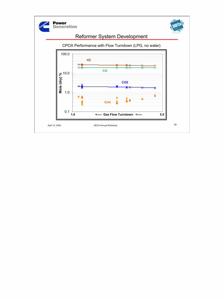
CPOX Performance with Flow Turndown (LPG, no water)
0.1
1.0
10.0
100.0
Mol
e (d
ry) %
H2
CH4
CO2
CO
1.0 <----- Gas Flow Turndown <----- 5.5
Reformer System Development
30
April 15, 2003 SECA Annual Workshop 30
EFS Holdings, LLC
Solid Oxide Fuel Cellsand Fuel Processors
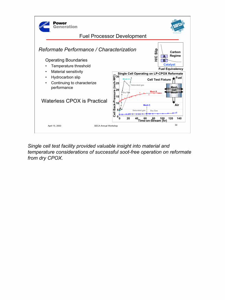
Fuel Processor Development
Operating Boundaries• Temperature threshold• Material sensitivity• Hydrocarbon slip• Continuing to characterize
performance
Single Cell Operating on LP-CPOX Reformate
0
5
10
15
20
25
30
0 20 40 60 80 100 120 140Time-on-Stream (hr)
Cel
l Bac
k-Pr
essu
re (i
nch-
WC
)
Mesh B
Mesh C
Mesh A
Dry Gas
Saturated gas
Saturated gas Dry Gas
Fuel
Air
MeshCell
Mesh
Cell Test Fixture
Reformate Performance / Characterization
Waterless CPOX is Practical
H/C
Slip
Fuel Equivalency
CarbonRegimeA
BCatalyst
Single cell test facility provided valuable insight into material andtemperature considerations of successful soot-free operation on reformatefrom dry CPOX.

31
April 15, 2003 SECA Annual Workshop 31
EFS Holdings, LLC
Solid Oxide Fuel Cellsand Fuel Processors
Fuel Processor Development
Testing in progress at single-cell test stand tocharacterize cell and reformate performance
Single-cell Test Stand
Micro-Reactor
Partial View of Fuel Cell Lab
32
April 15, 2003 SECA Annual Workshop 32
EFS Holdings, LLC
Solid Oxide Fuel Cellsand Fuel Processors
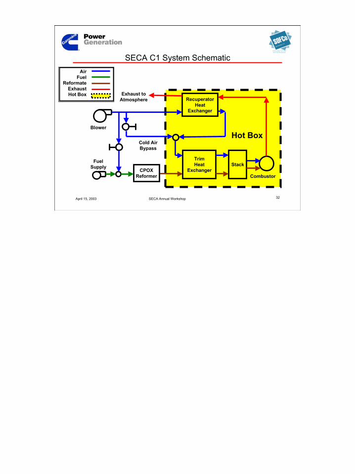
SECA C1 System Schematic
Stack
RecuperatorHeat
Exchanger
TrimHeat
Exchanger
Blower
Combustor
Exhaust toAtmosphere
CPOXReformer
FuelSupply
Cold AirBypass
Hot Box
AirFuel
ReformateExhaustHot Box

33
April 15, 2003 SECA Annual Workshop 33
EFS Holdings, LLC
Solid Oxide Fuel Cellsand Fuel Processors
ASPEN for System and Stack Analysis
Aspen fuel cell stack model• Steady-state and
transient• Benchmarked against
SOFCo’s proprietary cell/ stack model
• Also correlated to DOEsimplified stack model
ASPEN system model• System design and
operation
Stack Temperature
700
750
800
850
900
0 2 4 6 8 10 12
Position (cm)
Tem
pera
ture
(C)
50% Load no bypass 50% Load with bypass 100% Load
Aspen modeling provides valuable insight into system configuration for highefficiency part load operations within operating temperature limits.

34
April 15, 2003 SECA Annual Workshop 34
EFS Holdings, LLC
Solid Oxide Fuel Cellsand Fuel Processors
System Development
• C1 final design progressing– 1 kWe development fuel cell
with two, 10 cm 55-cell stacks
– Test by year-end with stacksimulators; 10 cm stacksinstalled early 2004
• C2 conceptual design started– Define fuel cell and battery
power split for 10 kWesystem
– 5 kWe demonstration fuel cellwith two, 15 cm 55-cell stacks
Hot Box Internals
35
April 15, 2003 SECA Annual Workshop 35
EFS Holdings, LLC
Solid Oxide Fuel Cellsand Fuel Processors
Cells, Stacks, Reformer, Hot Box Sub-System
• Analysis and modeling tools in place
• First generation prototype design onschedule
• Parallel paths in place to evolvesystems and components
• Encouraging progress with CPOXreformer

36
April 15, 2003 SECA Annual Workshop 36
EFS Holdings, LLC
Solid Oxide Fuel Cellsand Fuel Processors
Installation
Phase III target: same size envelope as Diesel Genset
0.5 m3 (17.4 ft3)
635mm(25”)
635mm(25”)
1220mm(48”)
Existing RV diesel genset product parameters.
37
April 15, 2003 SECA Annual Workshop 37
EFS Holdings, LLC
Solid Oxide Fuel Cellsand Fuel Processors
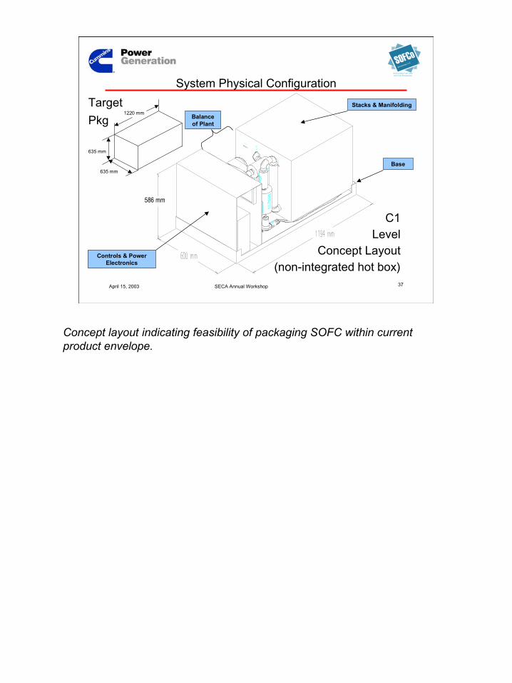
System Physical Configuration
586 mm
635 mm
635 mm
1220 mmTargetPkg
C1Level
Concept Layout(non-integrated hot box)
Stacks & Manifolding
Controls & PowerElectronics
Base
Balanceof Plant
Concept layout indicating feasibility of packaging SOFC within currentproduct envelope.

38
April 15, 2003 SECA Annual Workshop 38
EFS Holdings, LLC
Solid Oxide Fuel Cellsand Fuel Processors
Preliminary Design Flow LossesSample Calculated Pressure Drops Through System
Mixer
Pipe
CPOX
Filter
Pipe
TRIMHX
Pipe
STACK
Pipe
RECUP
Exh Pipe
BURNER
Blower
Out
PipeRecup
erator
PipePipePipe
0
5
10
15
20
25
30
35
40
Blower
OutMixe
rPipe
CPOXFilte
rPipe
TRIMHX
Pipe
STACKPipe
BURNERPipe
RECUPSystem Components from Inlet to Exhaust0.00
5.00
10.00
15.00
20.00
25.00
30.00
35.00
40.00Anode FlowCathode Flow
Boost or throttle main blower output to account for differential lossesleading up to stack outlet…design trade-off for performance and cost

39
April 15, 2003 SECA Annual Workshop 39
EFS Holdings, LLC
Solid Oxide Fuel Cellsand Fuel Processors
Sample C1 System Temperature Estimates
Ex Pipe
RECUP
Pipe
STACK
PipeTRIM
HXPipeFilte
r
Mixer
CPOX
BURNER
Blower
Out
Pipe
Recup
erator
PipePipePipe0
100
200
300
400
500
600
700
800
900
1000
Blower
OutMixe
rPipe
CPOXFilte
rPipe
TRIMHX
Pipe
STACK
Pipe
BURNERPipe
RECUP
Degr
ees
C
0
100
200
300
400
500
600
700
800
900
1000
Anode Temp
Cathode Temp
Sample System Temperature Modeling

40
April 15, 2003 SECA Annual Workshop 40
EFS Holdings, LLC
Solid Oxide Fuel Cellsand Fuel Processors
C1 Components Under Development
INLET
OUTLET
LINEAR SOLENOID
FlowControlValves Blower
CPG will source Balance of Plant components where possible, design anddevelop as required.
41
April 15, 2003 SECA Annual Workshop 41
EFS Holdings, LLC
Solid Oxide Fuel Cellsand Fuel Processors
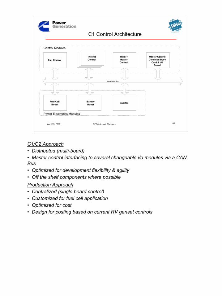
Master ControlDominion Base Card &
I/O BoardFan Control
Battery Boost InverterFuel Cell Boost
CAN Data Bus
Throttle ControllerThrottle ControllerThrottle ControllerMixer/Heater
Control
Control Modules
Power Electronics Modules
Fan ControlThrottleControl
Mixer /HeaterControl
Master ControlDominion Base
Card & I/OBoard
Fuel CellBoost
BatteryBoost Inverter
C1 Control Architecture
C1/C2 Approach• Distributed (multi-board)• Master control interfacing to several changeable i/o modules via a CANBus• Optimized for development flexibility & agility• Off the shelf components where possibleProduction Approach• Centralized (single board control)• Customized for fuel cell application• Optimized for cost• Design for costing based on current RV genset controls
42
April 15, 2003 SECA Annual Workshop 42
EFS Holdings, LLC
Solid Oxide Fuel Cellsand Fuel Processors
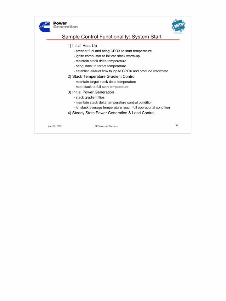
Sample Control Functionality: System Start1) Initial Heat Up
- preheat fuel and bring CPOX to start temperature- ignite combustor to initiate stack warm-up- maintain stack delta temperature- bring stack to target temperature- establish air/fuel flow to ignite CPOX and produce reformate
2) Stack Temperature Gradient Control- maintain target stack delta temperature- heat stack to full start temperature
3) Initial Power Generation- stack gradient flips- maintain stack delta temperature control condition- let stack average temperature reach full operational condition
4) Steady State Power Generation & Load Control

43
April 15, 2003 SECA Annual Workshop 43
EFS Holdings, LLC
Solid Oxide Fuel Cellsand Fuel Processors
• Two options forPower Electronicsarchitecture.
• Option 2 requirestransformer basedboost -- 50% moreexpensive thanOption 1.
• Option 1 onlyrequires inductorbased boost.
Power Electronics Architecture
44
April 15, 2003 SECA Annual Workshop 44
EFS Holdings, LLC
Solid Oxide Fuel Cellsand Fuel Processors
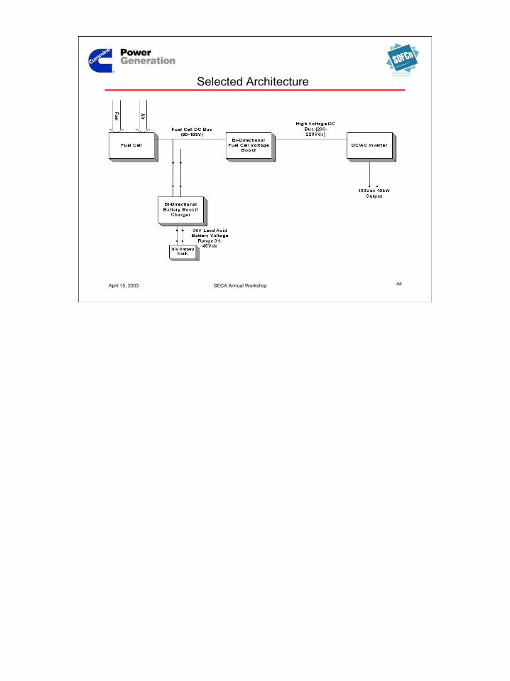
Selected Architecture

45
April 15, 2003 SECA Annual Workshop 45
EFS Holdings, LLC
Solid Oxide Fuel Cellsand Fuel Processors
– Bi-directional Voltage Fed Inverter• converts boosted DC buss to 120 VAC 60Hz
– Fuel Cell Boost• steps fuel cell output voltage to boosted DC buss
– Battery Boost• steps battery voltage to fuel cell buss voltage
– Microprocessor Control• coordinates BOP and Power electronics
Primary Power Electronics Components

46
April 15, 2003 SECA Annual Workshop 46
EFS Holdings, LLC
Solid Oxide Fuel Cellsand Fuel Processors
Sample Boost Efficiency
Typical DC-DC Boost Converter Efficiency
0
20
40
60
80
100
0 50 100 150 200 250 300 350
Current (Amps)
Eff.
%
Typical range for battery boost
Typical range for fuel cell boost
Battery boost and fuel cell boost are designed to place operating ranges inregion of optimum efficiency.

47
April 15, 2003 SECA Annual Workshop 47
EFS Holdings, LLC
Solid Oxide Fuel Cellsand Fuel Processors
Sample Inverter Performance
Sample Inverter Efficiency vs % Load
0
20
40
60
80
100
0 20 40 60 80 100% Load
Effic
ienc
y %
Power Stage Filter Total
Requirements for power quality and EMI/RFI must be taken into account ininverter design.
48
April 15, 2003 SECA Annual Workshop 48
EFS Holdings, LLC
Solid Oxide Fuel Cellsand Fuel Processors
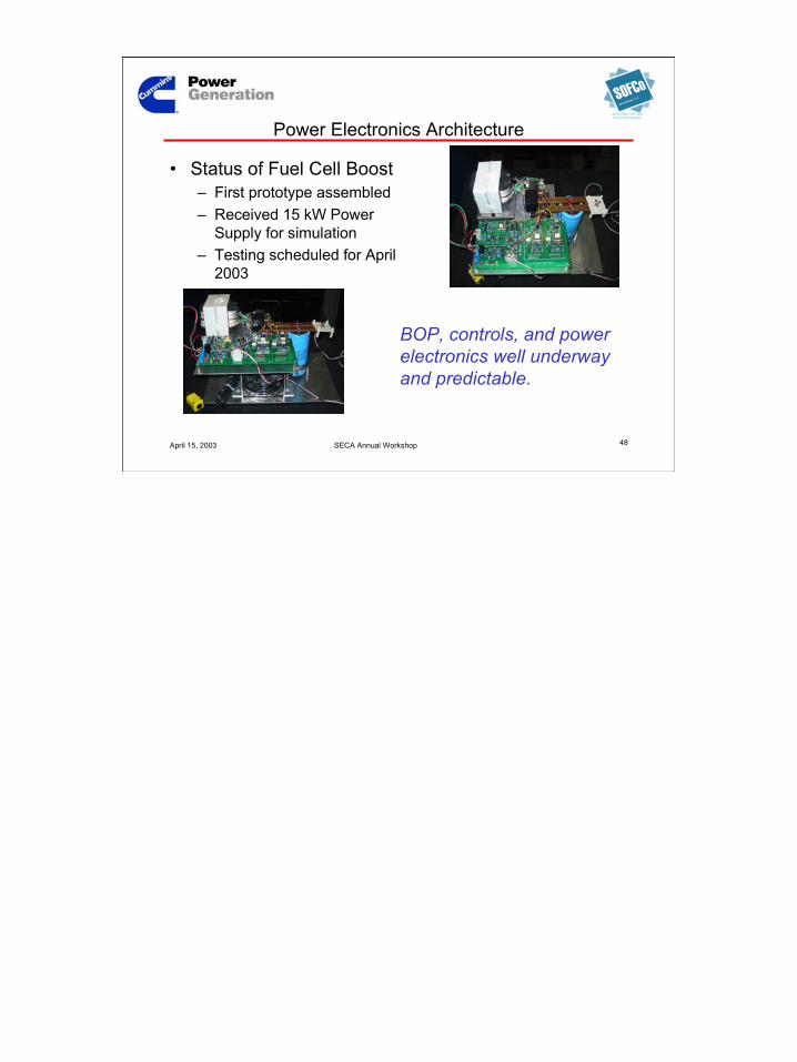
Power Electronics Architecture
• Status of Fuel Cell Boost– First prototype assembled– Received 15 kW Power
Supply for simulation– Testing scheduled for April
2003
BOP, controls, and powerelectronics well underwayand predictable.

49
April 15, 2003 SECA Annual Workshop 49
EFS Holdings, LLC
Solid Oxide Fuel Cellsand Fuel Processors
Summary
• Cummins Power Generation -- a technology-neutral worldwidedeveloper and manufacturer of power generation equipment withsignificant market share in target markets
• Cummins Power Generation Markets -- existing marketpresence in both stationary and mobile applications from 2kW to 2.5MW
• Cummins - SOFCoTeam -- with the portfolio of capabilitiesneeded to successfully commercialize the SOFC
• SECA Program Progress– analysis and modeling tools in place– first generation prototype design on schedule– parallel paths in place to evolve systems and components– encouraging progress with CPOX reformer– BOP, controls, and power electronics well underway and predictable

50
April 15, 2003 SECA Annual Workshop 50
EFS Holdings, LLC
Solid Oxide Fuel Cellsand Fuel Processors
Acknowledgements
DOE / NETL– Don Collins– Cary Smith– Joe Strakey– Wayne Surdoval– Bruce Utz– Mark Williams
CPG– Brad Palmer– Todd Romine– Charles Vesely SOFCo
– Eric Barringer– Cris DeBellis– Milind Kantak– Kurt Kneidel– Rodger McKain– Garry Roman– Greg Rush– Laurie Wessel
PNNL– Gary Mcvay– Prabhakar Singh– Marie Jimenez– Gloria Ruiz
SECA CoreTechnology Teams

51
April 15, 2003 SECA Annual Workshop 51
EFS Holdings, LLC
Solid Oxide Fuel Cellsand Fuel Processors
SECA ProgramCummins Power Generation
10kWe SOFC Power System Commercialization ProgramSeattle, Washington
April 15, 2003
This presentation was prepared with the support of the U.S.Department of Energy, under Award no. DE-FC26-01NT41244.
However, any opinions, findings, conclusions, or recommendationsexpressed herein are those of the author(s) and do not necessarily
reflect the views of the DOE.
SECA Annual Workshop