CULTIVATOR TABLE OF CONTENTS 43cc CULTIVATOR Introduction1 Manual Conventions2 Safety Rules3 Symbols...
29
OPERATOR’S MANUAL 43cc CULTIVATOR SAVE THESE INSTRUCTIONS Important safety instructions are included in this manual. MADE IN CHINA REV 100378-20180822 100378 MODEL NUMBER 12039 Smith Ave. Santa Fe Springs CA 90670 USA / 1-877-338-0999 www.championpowerequipment.com T w o Y e a r L i m it e d W a r r a n t y T w o Y e a r L i m it e d W a r r a n t y G a r a n ti e li m i t é e d e d e u x a n s G a r a n ti e li m i t é e d e d e u x a n s G a r a n t í a l i m i t a d a d e d o s a ñ o s G a r a n t í a l i m i t a d a d e d o s a ñ o s
Transcript of CULTIVATOR TABLE OF CONTENTS 43cc CULTIVATOR Introduction1 Manual Conventions2 Safety Rules3 Symbols...

OPERATOR’S MANUAL
43ccCULTIVATOR
SAVE THESE INSTRUCTIONS Important safety instructions are included in this manual.
MADE IN CHINAREV 100378-20180822
100378MODEL NUMBER
12039 Smith Ave.Santa Fe Springs CA 90670
USA / 1-877-338-0999www.championpowerequipment.com
Two Year Limited WarrantyTwo Year Limited Warranty
Garantie limité
e de
deu
x an
s
Garantie limité
e de
deu
x an
sGarantía limitada de dos años
Garantía limitada de dos años

Have questions or need assistance?Do not return this product to the store!
WE ARE HERE TO HELP!Visit our website:
www.championpowerequipment.comfor more info:
• Product Info & Updates• Frequently Asked Questions
• Tech Bulletins• Product Registration
– or –
Call our Customer Care Team Toll-Free at:
1-877-338-0999
*We are always working to improve our products. Therefore, the enclosed product may differ slightly from the image on the cover.
Parts Ordering:Mon – Fri 8:30 AM – 5:00 PM (PST/PDT)
Toll Free: 1-877-338-0999
100378
TABLE OF CONTENTS
43cc
CULTIVATOR
Introduction . . . . . . . . . . . . . . . . . . . . . . . . . . . . 1Manual Conventions . . . . . . . . . . . . . . . . . . . . . . . 2Safety Rules . . . . . . . . . . . . . . . . . . . . . . . . . . . . 3
Symbols . . . . . . . . . . . . . . . . . . . . . . . . . . . . . 3Things To Do . . . . . . . . . . . . . . . . . . . . . . . . . 5Things Not To Do . . . . . . . . . . . . . . . . . . . . . . 6
Controls and Features . . . . . . . . . . . . . . . . . . . . . 7Cultivator . . . . . . . . . . . . . . . . . . . . . . . . . . . . 7
Assembly . . . . . . . . . . . . . . . . . . . . . . . . . . . . . . 8Tine Instalation or Re-installation . . . . . . . . . . . 8Wheel Assembly . . . . . . . . . . . . . . . . . . . . . . . 8Handle Assembly . . . . . . . . . . . . . . . . . . . . . . 9Fuel . . . . . . . . . . . . . . . . . . . . . . . . . . . . . . . 9
How to mix fuel . . . . . . . . . . . . . . . . . . . . . 9Fueling the unit . . . . . . . . . . . . . . . . . . . . . 9
Operation . . . . . . . . . . . . . . . . . . . . . . . . . . . . . 11Starting Instructions . . . . . . . . . . . . . . . . . . . 11
Starting Your Cultivator for the First Time or When Cold . . . . . . . . . . . . . . . . . . 11Starting a Warm Engine . . . . . . . . . . . . . . . 12
Stopping the Engine . . . . . . . . . . . . . . . . . . . 12Special Feature (with Idle Set Properly and the Engine Running). . . . . . . . . . . . . . . . . . . . 12Tips for Extending Engine Life . . . . . . . . . . . . 12Cultivating . . . . . . . . . . . . . . . . . . . . . . . . . . 12
Now You’re ready to Use Your Cultivator . . . . 12You Can Even Control Depth . . . . . . . . . . . . 12
Maintenance and Storage . . . . . . . . . . . . . . . . . . 14Cultivator Maintenance . . . . . . . . . . . . . . . . . . 14
How to Check, Clean and Change the Air Filter . . . . . . . . . . . . . . . . . . . . . . . . . 14Cleaning Air Filter . . . . . . . . . . . . . . . . . . . 14Idle Speed Adjustment . . . . . . . . . . . . . . . 14Clear Blockages From the Fuel Line & Filter . 14Spark Plug . . . . . . . . . . . . . . . . . . . . . . . . 14
Muffler . . . . . . . . . . . . . . . . . . . . . . . . . . 14Intake Air Cooling Vent . . . . . . . . . . . . . . . 15Procedures to be Performed After Every 100 Hours of Use . . . . . . . . . . . . . . . 15Maintenance Schedule . . . . . . . . . . . . . . . . 15
Cultivator Storage . . . . . . . . . . . . . . . . . . . . . 15How to Prepare Your Cultivator for Restarting . . 16
Re-Starting problems after storage . . . . . . . 16Troubleshooting . . . . . . . . . . . . . . . . . . . . . . . . . 17
Starting Problems . . . . . . . . . . . . . . . . . . . . . 17Specifications . . . . . . . . . . . . . . . . . . . . . . . . . . 18
Engine Specifications . . . . . . . . . . . . . . . . . . 18Cultivator Specifications . . . . . . . . . . . . . . . . . 18Spark Plugs . . . . . . . . . . . . . . . . . . . . . . . . . 18Parts Diagram . . . . . . . . . . . . . . . . . . . . . . . . 19Parts List . . . . . . . . . . . . . . . . . . . . . . . . . . . 20Engine Parts Diagram . . . . . . . . . . . . . . . . . . 21Engine Parts List . . . . . . . . . . . . . . . . . . . . . 22

1
ENGLISH 100378
INTRODUCTION
Record the model and serial numbers as well as date and place of purchase for future reference. Have this information available when ordering parts and when making technical or warranty inquiries.
Champion Power Equipment Support
Model Number
Serial Number
Date of Purchase
Purchase Location
1-877-338-0999
100378
Congratulations on your purchase of a Champion Power Equipment (CPE) product. CPE designs, builds, and supports all of our products to strict specifications and guidelines. With proper product knowledge, safe use, and regular maintenance, this product should bring years of satisfying service.
Every effort has been made to ensure the accuracy and completeness of the information in this manual, and we reserve the right to change, alter and/or improve the product and this document at any time without prior notice.
Since CPE highly values how our products are designed, manufactured, operated and are serviced, and also highly value your safety and the safety of others, we would like you to take the time to review this product manual and other product materials thoroughly and be fully aware and knowledgeable of the assembly, operation, dangers and maintenance of the product before use. Fully familiarize yourself, and make sure others who plan on operating the product fully familiarize themselves too, with the proper safety and operation procedures before each use. Please always exercise common sense and always err on the side of caution when operating the product to ensure no accidents, property damage, or injury occurs. We want you to continue to use and be satisfied with your CPE product for years to come.

2
100378 ENGLISH
MANUAL CONVENTIONS
CAUTION indicates a potentially hazardous situation which, if not avoided, may result in minor or moderate injury.
CAUTION
CAUTION used without the safety alert symbol indicates a potentially hazardous situation which, if not avoided, may result in property damage.
CAUTION
This manual uses the following symbols to help differentiate between different kinds of information. The safety symbol is used with a key word to alert you to potential hazards in operating and owning power equipment.
Follow all safety messages to avoid or reduce the risk of serious injury or death.
DANGER indicates an imminently hazardous situation which, if not avoided, will result in death or serious injury.
DANGER
WARNING indicates a potentially hazardous situation which, if not avoided, could result in death or serious injury.
WARNINGIf you have questions regarding your cultivator, we can help. Please call our help line at 1-877-338-0999
NOTE

3
ENGLISH 100378
SAFETY RULES
Some of the following symbols may be used on this product. Please study them and learn their meaning. Proper interpretation of these symbols will allow you to more safely operate the product.
Symbols
Symbol Meaning
Precautions that involve your safety.
To reduce risk of injury, user must read and understand operator’s manual before using this product.
Always wear safety goggles, safety glasses with side shields, or a full face shield, as well as hearing protection when using this product.
Keep all bystanders at least 50 ft. (15.2 m) away.
Keep hands away from rotating tines.
Keep feet away from rotating tines.
Engine ON / START / RUN
Engine OFF or STOP
4
100378 ENGLISH
SAFETY RULES
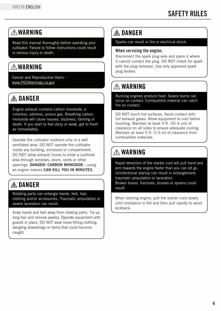
Read this manual thoroughly before operating your cultivator. Failure to follow instructions could result in serious injury or death.
WARNING
Engine exhaust contains carbon monoxide, a colorless, odorless, poison gas. Breathing carbon monoxide will cause nausea, dizziness, fainting or death. If you start to feel dizzy or weak, get to fresh air immediately.
DANGER
Operate the cultivator outdoors only in a well ventilated area. DO NOT operate the cultivator inside any building, enclosure or compartment.DO NOT allow exhaust fumes to enter a confined area through windows, doors, vents or other openings. DANGER: CARBON MONOXIDE - using an engine indoors CAN KILL YOU IN MINUTES.
Rotating parts can entangle hands, feet, hair, clothing and/or accessories. Traumatic amputation or severe laceration can result.
DANGER
Keep hands and feet away from rotating parts. Tie up long hair and remove jewelry. Operate equipment with guards in place. DO NOT wear loose-fitting clothing, dangling drawstrings or items that could become caught.
Sparks can result in fire or electrical shock.
DANGER
When servicing the engine:Disconnect the spark plug wire and place it where it cannot contact the plug. DO NOT check for spark with the plug removed. Use only approved spark plug testers.
Running engines produce heat. Severe burns can occur on contact. Combustible material can catch fire on contact.
DO NOT touch hot surfaces. Avoid contact with hot exhaust gases. Allow equipment to cool before touching. Maintain at least 3 ft. (91.4 cm) of clearance on all sides to ensure adequate cooling. Maintain at least 5 ft. (1.5 m) of clearance from combustible materials.
WARNING
Rapid retraction of the starter cord will pull hand and arm towards the engine faster than you can let go. Unintentional startup can result in entanglement, traumatic amputation or laceration. Broken bones, fractures, bruises or sprains could result.
When starting engine, pull the starter cord slowly until resistance is felt and then pull rapidly to avoid kickback.
WARNING
Cancer and Reproductive Harm – www.P65Warnings.ca.gov
WARNING

5
ENGLISH 100378
SAFETY RULES
Fuel and fuel vapors are highly flammable and extremely explosive.
Fire or explosion can cause severe burns or death.
Unintentional startup can result in entanglement, traumatic amputation or laceration.
DANGER
When adding or removing fuel:Turn the engine off and let it cool for at least two minutes before removing the fuel cap. Loosen the cap slowly to relieve pressure in the tank.
Only fill or drain fuel outdoors in a well-ventilated area.
DO NOT pump gas directly into the engine at the gas station. Use an approved container to transfer the fuel to the engine.
DO NOT overfill the fuel tank.
Always keep fuel away from sparks, open flames, pilot lights, heat and other sources of ignition.
DO NOT light or smoke cigarettes.
When starting the engine:DO NOT attempt to start a damaged engine. Make certain that the gas cap, air filter, spark plug, fuel lines and exhaust system are properly in place. Allow spilled fuel to evaporate fully before attempting to start the engine.
Make certain that the cultivator is resting firmly on level ground.
1. Always keep a firm grip on both handles while the tines are moving and/or the engine is running. BE AWARE!! The tines may coast after throttle trigger is released. Make sure tines have come to a complete stop and engine is off before letting go of the cultivator handles.
2. Always maintain a firm footing and good balance. Do not overreach while operating the cultivator. Before you start to use the cultivator, check the work area for obstacles that might cause you to lose your footing, balance or control of the machine.
3. Thoroughly inspect the area where equipment is to be used and remove all objects, that can be thrown by the machine or cause it to jam.
4. Keep all bystanders, children, and pets at least 50 ft. (15.2 m) away.
5. Always stay alert. Watch what you are doing and use common sense. Do not operate unit when fatigued.
6. Always dress properly. Do not wear loose clothing or jewelry, they might get caught in moving parts. Use sturdy gloves. Gloves reduce the transmission of vibration to your hands. Prolonged exposure to vibration can cause numbness, fatigue and other ailments.
7. While working, always wear substantial footwear and long trousers. Do not operate the equipment when barefoot or wearing open sandals.
8. Always wear ear and eye protection. Eye protection must meet ANSI Z87.1. To avoid hearing damage, we recommend hearing protection be worn whenever using the equipment.
9. To reduce fire hazard, keep the engine, and petrol/gas storage area free of vegetative material and excessive grease.
10. Start the engine carefully, according to the instructions and with feet well away from the tines.
11. Always operate the cultivator with good visibility
12. Keep all nuts, bolts and screws tight to be sure the equipment is in safe working condition.
13. Use extreme caution when reversing or pulling the machine towards you.
14. Stop the engine and disconnect the spark plug before unclogging the tines and when making any repairs, adjustments, or inspections.
15. Work only in daylight or good artificial light.
16. Always be sure of your footing on slopes.
17. Exercise extreme caution when changing direction on slopes.
Things To Do

6
100378 ENGLISH
11. Don’t fuel, refuel or check fuel while smoking, or near an open flame or other ignition source. Stop engine and be sure it is cool before refueling.
12. Don’t leave the engine running while the cultivator is unattended. Stop engine before putting the cultivator down or while transporting from one place to another.
13. Don’t refuel, start or run this cultivator indoors or in an improperly ventilated area.
14. Don’t run engine when electrical system causes spark outside the cylinder. During periodic checks of the spark plug, keep plug a safe distance from cylinder to avoid burning of evaporated fuel from cylinder.
15. Don’t check for spark with spark plug or plug wire removed. Use an approved tester.
16. Don’t crank engine with spark plug removed unless spark plug wire is disconnected. Sparks can ignite fumes.
17. Don’t run engine when the odor of gasoline is present or other explosive conditions exist.
18. Don’t operate the unit if gasoline is spilled. Clean up spill completely before starting engine.
19. Don’t operate your cultivator if there is an accumulation of debris around the muffler, and cooling fins.
20. Don’t touch hot mufflers, cylinders or cooling fins as contact may cause serious burns.
21. Don’t change the engine governor setting or over speed the engine.
SAFETY RULES
18. Always keep a safe distance between two or more people when working together.
19. Always inspect your unit before each use and ensure that all handles, guards and fasteners are secure, operating, and in place.
20. Always maintain and examine your cultivator with care. Follow maintenance instructions given in manual.
21. Always use fresh gasoline. Stale gasoline can cause engine damage.
22. Always store fuel in containers specifically designed for that purpose.
23. Always pull starter cord slowly until resistance is felt. Then pull cord rapidly to avoid kickback and prevent arm or hand injury.
24. Stop the engine whenever you leave the machine.
25. Allow the engine to cool before storing in any enclosure.
26. If the fuel tank needs to be drained, this should be done outdoors.
1. Don’t use the cultivator with one hand. Keep both hands on the handles with fingers and thumbs encircling the handles while tines are moving and engine is running.
2. Don’t put hands or feet near or under tines.
3. Do not use near underground electric cables, telephone lines, pipes, or hoses. If in doubt, contact your utility or telephone company to locate underground services.
4. Don’t overreach. Keep a good footing at all times.
5. Don’t run with the machine only walk.
6. Don’t work on excessively steep slopes.
7. Don’t attempt to clear tines while they are moving. Never try to remove jammed material before switching the engine off and making sure the tines have stopped completely.
8. Don’t allow children to operate this cultivator.
9. Don’t allow adults to operate the equipment without proper instruction.
10. Don’t operate while under the influence of alcohol or drugs.
Things Not To Do
Things To Do Cont’d. Things Not To Do Cont’d.

7
ENGLISH 100378
CONTROLS AND FEATURES
Read this owner’s manual before operating your cultivator. Familiarize yourself with the location and function of the controls and features. Save this manual for future reference.
(1) Fender Guard
(2) Fuel Tank – 0.3 gal (1.1 L), 50:1 ratio
(3) Engine – 43cc
(4) Middle Handle
(5) Right Handle
(6) Throttle
(7) Left Handle
(8) Knob Handle
(9) Lower Handle
(10) Axle Assembly
(11) Wheel
(12) Tine Assembly
Cultivator
6
7
8
9
10
11
2
1
3
4
5
12

8
100378 ENGLISH
ASSEMBLY
Read this owner’s manual before operating your cultivator.
If you have any questions regarding the assembly of your cultivator, call our help line at 1-877-338-0999. Please have your serial number and model number available.
Wheel Assembly1. Remove the cotter pin from the clevis pin.
Tine Installation or Reinstallation1. First, slide the inside tines onto each end of the tine
shaft. One inside tine is stamped with a “B” and the other is stamped with a “C”.
2. Slide the outside tine “A” and tine “D” onto each end of the shaft next. The tines should be installed in the correct order so that they are positioned right to left A, B, C, D, as viewed from the front of the cultivator. Make sure that the hub collars on both the right and left pairs of tines face each other so that there is adequate spacing between the tine blades.
ABCD
3. Slide a washer on each side.
4. Insert the cotter pins into the holes at each end of the tine shaft to lock the tines into place.
2. Remove the clevis pin from the axle assembly.
3. Place wheel on each end of the axle. Note installation direction - ring faces outwards.
Ring facesoutwards
4. Slide a washer onto the axle on each side. Add the nut and hand tighten.

9
ENGLISH 100378
ASSEMBLY
Handle Assembly
Handle Assembly Cont’d
Fuel
1. Attach the middle handle to the lower handle using the knobs and bolts provided. The knobs should be on the outside.
Your cultivator is powered by a two stroke engine which requires a fuel mixture of gasoline and lubricating oil.
Use a mixture of 50 parts unleaded regular gasoline and 1 part two-stroke oil (50:1.) Use unleaded gasoline intended for motor vehicle use with an octane rating of 85 or higher. Never use fuel containing more than 10% ethanol.
Recommended mixing ratio Gasoline 50: Oil 1
Exhaust emission are controlled by the fundamental engine parameters and components (eq. carburetors, ignition timing and port timing) without addition of any major hardware or the introduction of an inert material during combustion.
How to mix fuel1. Pour 1 gal. (3.8 L) of the gasoline into a safe
container. Do not mix the fuel and oil in the engine fuel tank.
2. Add 2.6 oz (76 mL) of two-cycle engine oil to the gasoline and mix well. Screw the cap onto the gasoline can. Then swirl the can to blend the oil and gas.
Fueling the unit1. Carefully pour the fuel mix into the cultivator’s fuel
tank.
2. Only fill the fuel tank to 80% of the full capacity.
3. Fasten the fuel cap securely and wipe up any fuel spillage around the unit.
2. Attach the left handle and right handle to the middle handle using the knobs and bolts provided. The knobs should be on the outside.
lower handle
middle handle
middle handlerighthandle
lefthandle
Wheel Assembly Cont’d.5. Snap hubcap to outside of each wheel.
6. Attach wheel assembly to main body, reverse steps 1-2.

10
100378 ESPAÑOL
MONTAJE
– Siempre vuelva a mesclar el combustible de 2 tiempos antes de poner combustible en su cultivador. Nunca corra su cultivador en gasolina solamente. Esto dañará su motor y anulará las garantías.
– Siempre use un recipiente de gasolina limpio y siempre use gasolina sin plomo con menos de 10% etanol.
– Nunca intente de mesclar el aceite y la gasolina en el tanque de combustible del motor
– Siempre mescle aceite y gasolina en las proporciones apropiadas : 2.6 oz (76 mL) de aceite de motor de 2 tiempos a 1 galón (3.8 L). Combustible pre-mixto como 50:1 TruFuel también son una buena opción para usar en su cultivador.
– Etanol – Niveles alto de etanol puede causar la deterioro de partes de goma y/o plástico y la perturbación de la lubricación del aceite. Nunca use combustible con contenido de más de 10% etanol.
IMPORTANTE
NO use una mescla de aceite/gasolina vieja o correosa. Siempre use la mescla apropiada de aceite/gasolina. El no seguir estas instrucciones causarán que su motor sufra daño rápido y permanente, y anulará la garantía del motor.
NOTA
Combustible continuación.
El combustible el extremadamente inflamable. Manéjelo con cuidado. Mantenga alejado de fuentes de ignición. NO fume mientras pone combustible en la unidad.
PELIGRO
Gasolina
gal. (L)
1 gal.
(3.8 L)
2 gal.
(7.6 L)
3 gal.
(11.4 L)
4 gal.
(15.1 L)
5 gal.
(18.9 L)
Aceite 2 Tiempos
oz. (mL)
2.6 oz.
(76 mL)
5.1 oz.
(152 mL)
7.7 oz.
(228 mL)
10.2 oz.
(302 mL)
12.9 oz.
(378 mL)
11
ENGLISH 100378
OPERATION
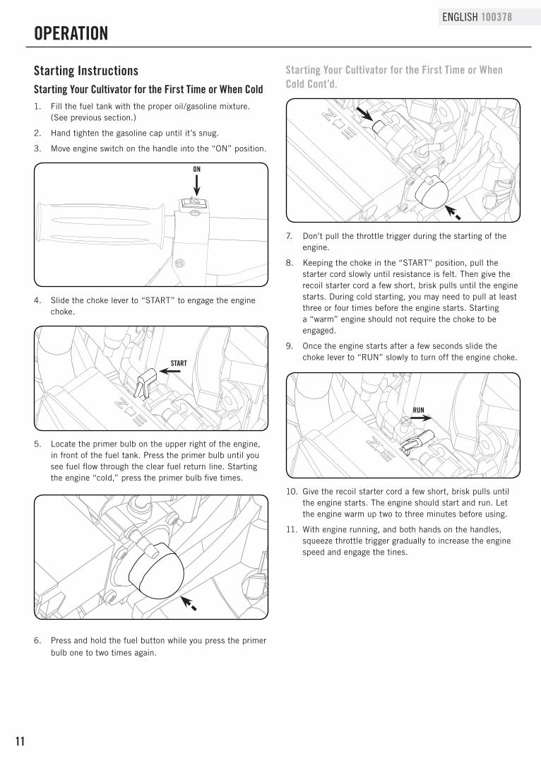
Starting InstructionsStarting Your Cultivator for the First Time or When Cold
Starting Your Cultivator for the First Time or When Cold Cont’d.
1. Fill the fuel tank with the proper oil/gasoline mixture. (See previous section.)
2. Hand tighten the gasoline cap until it’s snug.
3. Move engine switch on the handle into the “ON” position.
ON
START
RUN
4. Slide the choke lever to “START” to engage the engine choke.
5. Locate the primer bulb on the upper right of the engine, in front of the fuel tank. Press the primer bulb until you see fuel flow through the clear fuel return line. Starting the engine “cold,” press the primer bulb five times.
6. Press and hold the fuel button while you press the primer bulb one to two times again.
7. Don’t pull the throttle trigger during the starting of the engine.
8. Keeping the choke in the “START” position, pull the starter cord slowly until resistance is felt. Then give the recoil starter cord a few short, brisk pulls until the engine starts. During cold starting, you may need to pull at least three or four times before the engine starts. Starting a “warm” engine should not require the choke to be engaged.
9. Once the engine starts after a few seconds slide the choke lever to “RUN” slowly to turn off the engine choke.
10. Give the recoil starter cord a few short, brisk pulls until the engine starts. The engine should start and run. Let the engine warm up two to three minutes before using.
11. With engine running, and both hands on the handles, squeeze throttle trigger gradually to increase the engine speed and engage the tines.

12
100378 ENGLISH
OPERATION
Stopping the Engine
Special Feature (with Idle Set Properly and the Engine Running).
Tips for Extending Engine Life
Tips for Extending Engine Life Cont’d.Starting a Warm Engine
STOP
Simply move the engine switch to “STOP” position. This will stop the engine instantly. If it should ever fail to do so, just slide the choke lever to “START” to stall the engine.
Even when the engine is running, the tines won’t turn unless you press the throttle lever on the handlebars. And, when you release the throttle lever, the tines will stop.
After you start the engine, let your cultivator warm up for two to three minutes before you use it. Then, before you put your cultivator away, let it idle for a minute to give the engine a chance to cool down.
Always shake mixed fuel before adding to the cultivator to ensure proper oil content.
Only use fuel less than 60 days old.
1. Move the engine switch to the “ON” position.
2. Ensure the choke lever is in the “RUN” position.
3. If there is no fuel in the clear return line, push primer bulb 3-4 times or until fuel is visible in the line.
4. Pull the starter cord slowly until resistance is felt. Then give the recoil starter cord a few short, brisk pulls until the engine fires.
5. If engine fails to start in 4 pulls, use “Cold” starting procedure
6. With engine running, and both hands on the handles, squeeze throttle trigger gradually to increase the engine speed and engage the tines.
If the engine does not stop when the engine switch is moved in the “STOP” position, release the throttle. Allow the engine to idle.
Put the cultivator down and slide the choke lever to cold start (closed) position.
Check and return engine switch to the “ON” position before starting the engine again.
WARNING
CultivatingNow You’re ready to Use Your CultivatorIf you’ve used a cultivator in the past you know that you walk behind a cultivator as the soil is churned. Your Champion cultivator may surprise you in the fact it works best if you pull it towards you. It tills best when you pull it backward! You see, when you pull your cultivator backward, it provides extra resistance to the tines, so they dig deeper. What’s more when you go backward, you create a soil bed that stays light and fluffy ready for plating.
Place your cultivator at the head of the row or area you want to cultivate. Start it up. Then use an easy rocking motion to pull your cultivator backward and then, let it move forward. Repeating this motion while moving the cultivator left and right will maximize the performance of the product and produce optimum planting conditions by helping you cultivate deeper.
Keep repeating these steps until you’ve tilled an entire row. Start again on the next row. It’s much like running a vacuum cleaner!
You Can Even Control Depth
For Deeper Cultivating: Move your cultivator slowly back and forth, as you would a vacuum cleaner. Work the same area over and over until you’ve dug to your desired depth.
You can use your transport wheel / depth gauge assembly to set specific working depth for your cultivator, see the diagram.
For Shallow Cultivating and Weeding:You can quickly skim over an area to weed or scarify the ground for seeding. Simply move the cultivator quickly over your soil surface back and forth, left and right allowing the tines to float on the top of the ground.

13
ENGLISH 100378
OPERATION
You Can Even Control Depth Cont’d. You Can Even Control Depth Cont’d.
TransportingPosition
WorkingPosition
Working withoutwheels or depth gauge
Remember, any cultivator will tangle in tall grass, stringy vines, or overly large weeds. So, if you plan to cultivate in these conditions first use a pruner or brush cutter to chop up the overgrowth. If the tines become tangled, turn the engine off and allow the tines to full come to a stop before trying to clear them.
If your tines get jammed or entangled, shut off the engine at once.
Remove the obstruction while the engine is off.
NEVER try to remove an obstruction while the engine is running. SERIOUS INJURY CAN RESULT.
WARNING
For Big Weeds or Tough Roots:Let your cultivator rock back and forth over the tough spot, until the tines slice through the weed or root.
The operator of this cultivator is responsible for accidents or hazards occurring to himself, other people or their property.
DANGER

14
100378 ENGLISH
Clear Blockages From the Fuel Line & Filter Cont’d.
Check the air filter every 25 hours of use or more frequently if used under dusty conditions. A clogged air filter may increase fuel consumption while cutting down the engine power. Never operate the cultivator without the air filter or with a deformed filter element because unfiltered dusty air will quickly ruin the engine.
Cleaning Air Filter1. Remove the air cleaner cover by pulling the tab on
side and take out the filter element.
2. Use mild detergent and warm water to clean the filter element. After cleaning, air dry the element completely and moisten with a small amount of motor oil.
3. Place the filter element into the air cleaner housing and press the cover against the housing until it clicks.
Idle Speed Adjustment1. Warm up engine before adjusting idle speed.
2. The idle speed adjustment screw controls the throttle opening at idle position.
3. When the engine tends to stop frequently at idling mode, turn the adjusting screw clock wise.
4. If the tines continue to rotate after releasing the trigger, turn the adjusting screw counter-clockwise.
Clear Blockages From the Fuel Line & Filter1. After you’ve used your cultivator for a few seasons,
check for blockages in the fuel tank and fuel filter. Such blockages can keep your cultivator from starting and running properly.
2. Clear any blockages you see in the tank or fuel line, replace the fuel filter if needed.
Spark Plug1. Starting failure and mis-firing are often caused by a
fouled spark plug. Clean the spark plug and check the that the plug gap is in the correct range, replace the plug if necessary (0.5 - 0.7 mm {0.020 - 0.028 in.}).
2. To install the spark plug first turn the plug until it is finger tight, then tighten it a quarter turn more with a socket wrench (19 mm).
Muffler – Inspect periodically the muffler for loose fasteners,
any damage or corrosion or blockage caused by insect nests. If any sign of exhaust leakage is found, stop using the machine and have it repaired immediately.
Note that failing to do so may result in the engine catching on fire.
WARNING
MAINTENANCE AND STORAGE
How to Check, Clean and Change the Air Filter
Cultivator Maintenance
The fuel filter is located inside the tank.
NOTE
DO NOT overtighten the spark plug.
CAUTION
The cultivator uses NHSP L8RTC or NGK BPMR7A spark plug. Use an exact replacement and replace annually.
NOTE
15
ENGLISH 100378
MAINTENANCE AND STORAGE
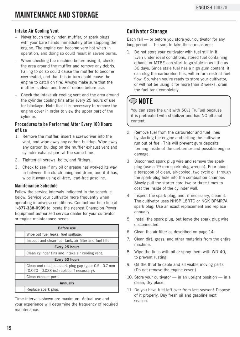
Intake Air Cooling Vent – Never touch the cylinder, muffler, or spark plugs
with your bare hands immediately after stopping the engine. The engine can become very hot when in operation, and doing so could result in severe burns.
– When checking the machine before using it, check the area around the muffler and remove any debris. Failing to do so could cause the muffler to become overheated, and that this in turn could cause the engine to catch on fire. Always make sure that the muffler is clean and free of debris before use.
– Check the intake air cooling vent and the area around the cylinder cooling fins after every 25 hours of use for blockage. Note that it is necessary to remove the engine cover in order to view the upper part of the cylinder.
Procedures to be Performed After Every 100 Hours of Use1. Remove the muffler, insert a screwdriver into the
vent, and wipe away any carbon buildup. Wipe away any carbon buildup on the muffler exhaust vent and cylinder exhaust port at the same time.
2. Tighten all screws, bolts, and fittings.
3. Check to see if any oil or grease has worked its way in between the clutch lining and drum, and if it has, wipe it away using oil-free, lead-free gasoline.
Each fall — or before you store your cultivator for any long period — be sure to take these measures:
1. Do not store your cultivator with fuel still in it. Even under ideal conditions, stored fuel containing ethanol or MTBE can start to go stale in as little as 30 days. Since stale fuel has a high gum content, it can clog the carburetor, this, will in turn restrict fuel flow. So, when you’re ready to store your cultivator, or will not be using it for more than 2 weeks, drain the fuel tank completely.
Cultivator Storage
You can store the unit with 50:1 TruFuel because it is pretreated with stabilizer and has NO ethanol content.
NOTE
2. Remove fuel from the carburetor and fuel lines by starting the engine and letting the cultivator run out of fuel. This will prevent gum deposits forming inside of the carburetor and possible engine damage.
3. Disconnect spark plug wire and remove the spark plug (use a 19 mm spark-plug wrench). Pour about a teaspoon of clean, air-cooled, two cycle oil through the spark-plug hole into the combustion chamber. Slowly pull the starter cord two or three times to coat the inside of the cylinder wall.
4. Inspect the spark plug, and, if necessary, clean it. The cultivator uses NHSP L8RTC or NGK BPMR7A spark plug. Use an exact replacement and replace annually.
5. Install the spark plug, but leave the spark plug wire disconnected.
6. Clean the air filter as described on page 14.
7. Clean dirt, grass, and other materials from the entire machine.
8. Wipe the tines with oil or spray them with WD-40, to prevent rusting.
9. Oil the throttle cable and all visible moving parts.(Do not remove the engine cover.)
10. Store your cultivator — in an upright position — in a clean, dry place.
11. Do you have fuel left over from last season? Dispose of it properly. Buy fresh oil and gasoline next season.
Before use
Wipe out fuel leaks, fuel spillage.
Inspect and clean fuel tank, air filter and fuel filter.
Every 25 hours
Clean cylinder fins and intake air cooling vent.
Every 50 hours
Clean and readjust spark plug gap (gap: 0.5 - 0.7 mm {0.020 - 0.028 in.} replace if necessary).
Clean exhaust port.
Annually
Replace spark plug.
Maintenance ScheduleFollow the service intervals indicated in the schedule below. Service your cultivator more frequently when operating in adverse conditions. Contact our help line at 1-877-338-0999 to locate the nearest Champion Power Equipment authorized service dealer for your cultivator or engine maintenance needs.
Time intervals shown are maximum. Actual use and your experience will determine the frequency of required maintenance.

16
100378 ENGLISH
MAINTENANCE AND STORAGE
In the Spring, when you take your cultivator out of storage, remove the spark plug. Pull the starter cord three or four times to clean oil from the combustion chamber. Wipe oil from the spark plug. Place the spark plug back into the cylinder. Reconnect the spark plug wire back on the spark plug. Then follow the steps to refuel and restart your cultivator.
Re-Starting problems after storageIf your cultivator won’t restart in the Spring - or if it lacks its usual power - the carburetor may need attention or the spark plug may be at fault. Check to see if the plug is fouled with oily black deposits. Clean or replace it if it is.
Also, check whether the center electrode is rounded at the end, or if the ground electrode is worn. If either is the case, you should replace it with a NHSP L8RTC or NGK BPMR7A spark plug. Use a 19 mm spark-plug wrench to install it. Adjust the plug gap to 0.5 - 0.7 mm (0.020 - 0.028 in.). To install the spark plug first turn the plug until it is finger tight, then tighten it a quarter turn more with a socket wrench.
How to Prepare Your Cultivator for Restarting
To avoid possible damage to the threads, do not try to remove the plug from a hot aluminum cylinder head.
NOTE

17
ENGLISH 100378
TROUBLESHOOTING
Starting Problems Starting Problems Cont’d
If you follow the normal starting procedure, you should have no problem starting your cultivator. But, just in case you do have problems, here’s what to do:
1. Make sure the engine switch is in the “ON” position. If the switch was in the “STOP” position when you pulled the cord, you may have flooded the engine. Even if the engine switch is in the “ON” position, it is possible to flood the engine. The smell of fuel can be a sign the engine is flooded.
a. Flooded Engine Procedure:
i. First, examine the spark plug. Use a 19 mm spark plug wrench.
ii. Remove the cap over the spark plug.
To avoid possible damage to the threads, do not try to remove the plug from a hot engine.
IMPORTANT Never use starting fluids. Starting fluids will cause permanent engine damage. Using them will void the warranty.
IMPORTANT
iii. Unscrew the spark plug.
iv. If the end of the spark plug is wet, the engine may be flooded. Make sure the switch is in the “Stop” position, disconnect spark plug wire and remove plug. Use a paper towel or a clean rag to dry the spark plug, then, with the spark plug out of the engine, pull the starter cord several times. Shake the fuel out of the inside of the plug and air dry. Next, replace the spark plug. Use the wrench to tighten it and replace the cap. Next, put the switch in the “Start” position and pull the choke lever into the “Start” position. Pull the starter cord three or four times until the engine coughs or sputters. Open the choke (move the choke lever to the “Run” position) and pull the cord a few times. The engine should start and run.
2. If the end of the spark plug is dry, check to see if the fuel line is blocked. The fuel line runs from the fuel tank to the carburetor. Pull it off at the carburetor end. Fuel should drip slowly from the line. Wipe off any excess or spilled fuel.
If fuel does not drip from the line, check the line for any bends or pinches. Kinks in the line restrict the flow of fuel to the engine. Just straighten out the line. Reconnect. Then follow the normal starting procedure.
If fuel drips too freely, the line may be disconnected from the fuel filter. You’ll find the fuel filter inside the fuel tank. Just re-attach the line to the filter, and put the filter back in the tank. Then follow the normal starting procedure.
Make sure the engine switch is in the top position.Keep plug wire away from engine to avoid unintentional spark.
WARNING

18
100378 ENGLISH
TROUBLESHOOTING
Cultivator Specifications – Fuel/Oil Ratio . . . . . . . . . . . . . . . . . . . . . . . .50:1
– Fuel Capacity . . . . . . . . . . . . . . . . .0.3 gal. (1.1 L)
– Gross Weight . . . . . . . . . . . . . . 43.4 lb. (19.7 kg)
– Net Weight . . . . . . . . . . . . . . . . .36.4 lb. (16.5 kg)
– Height . . . . . . . . . . . . . . . . . . . . 38.6 in. (98 cm)
– Width . . . . . . . . . . . . . . . . . . . . 18.9 in. (48 cm)
– Length. . . . . . . . . . . . . . . . . . . . 30.3 in. (77 cm)
SPECIFICATIONS
Engine Specifications – Model . . . . . . . . . . . . . . . . . . . . . . . . . 1E40F-2E
– Displacement . . . . . . . . . . . . . . . . . . . . . . . .43cc
– Type . . . . . . . . . . . . . . . . . . . . . . . . . . . 2-Stroke
– Start Type . . . . . . . . . . . . . . . . . . . . . . . . . Recoil
Spark PlugsOEM spark plug: NHSP L8RTCReplacement spark plug: NGK BPMR7A or equivalent. Make certain the spark plug gap is 0.5 - 0.7 mm (0.020 - 0.028 in.)
For further technical support:
Technical Service
Mon – Fri 8:30 AM – 5:00 PM (PST/PDT)
Toll Free: 1-877-338-0999
Problem Check Cause Solution
Starting Failure
Fuel tank Incorrect fuel Drain and fill with correct fuel
Fuel filter Fuel filter is clogged Replace fuel filter
Flooded engine Multiple
Let unit sit to air out (15 minutes) or remove spark plug and clean per instruction in manual
Sparking (no spark) Spark plug is fouled/ wet, plug gap is incorrect
Clean/ dry, correct gap: 0.5 - 0.7 mm (0.020 - 0.028 in.)
Engine starts but does not keep running/ hard re-starting
Fuel Tank Incorrect fuel Drain and fill with correct fuel
Muffler, cylinder (exhaust port)
Carbon is built-up or insect nest in exhaust port
Wipe away and or clean out
Air cleaner Clogged with dust Wash with mild detergent and water, dry thoroughly

19
ENGLISH 100378
Parts Diagram
SPECIFICATIONS
1 23
56
7
1
48
9
10
11
12
13
15
14
15
16
17
18
20
14
21
2223
2425
24232221
26
27
28
30
31 32 33
34 35 36 37 38 39 35
40
41
4243
4445
46
47
444342
49
52
5354
5556
57
62 6350 51
60
61
57
54
53
48
5859
5859
5859
5859
14
19
29
64

20
100378 ENGLISHParts List
# Part Number Description Qty1 711.200702.00 Cover, Handle 2
2 711.324010.00 Throttle Lever 1
3 1.896.035 Circlip Ø3.5 1
4 1.97.1.05 Washer Ø5 1
5 711.324020.00 Throttle Bracket 1
6 1.15865.1.4819 Screw ST4.8 x 19 1
7 5.1010.005 Switch Assembly 1
8 711.324030.00 Pin 1
9 711.324040.00 Throttle Cable Assembly 1
10 100378.21.10 Connector Wire 1
11 711.321010.00 Right Handle 1
12 711.321020.00 Middle Handle 1
13 711.321030.00 Left Handle 1
14 2.08.084 Capscrew M8 x 45 8
15 2.02.035 Knob-Handle M8 8
16 2.99.002 Tie Strap 2
17 711.321040.00 Lower Handle 1
18 1.5789.08150.1 Bolt M8 x 150 2
19 5.1010.005.00 Waterproof Cover, Switch 1
20 1.6187.1.08.1 Lock Nut M8 2
21 711.323012.00 Wheel Cap 2
22 1.29.2.0612.1 Screw M6 x 12 2
23 1.96.06.1 Washer Ø6 2
24 711.323011.00 Wheel Assembly 2
25 711.323020.00 Axle Assembly 1
26 2.16.003 Pin Ø3 , "R" Shape 1
27 711.323030.00 Bracket Assembly 1
28 1.5786.0635 Bolt M6 x 35 2
29 1.97.1.06 Sealing Washer Ø6 2
30 711.323040.00 Clevis Pin 8 x 18 1
31 1.6187.1.06 Lock Nut M6 2
32 1.6172.1.10 Nut M10 1
33 711.322001.00 Clutch Drum 1
34 711.322002.00 Big Bushing, Cuprum 1
35 711.322008.00 Roller Bearing 61901-2Z 4
36 711.322004.00 Washer 1
37 711.322005.00 Roller Bearing 6002-2RS 1
38 711.322006.00 Worm Thrust Bearing 51202 1
39 711.322009.00 Worm Shaft 1
40 1.9074.13.0618 Bolt M6 x 18 6
41 711.322013.00 Left Gear Housing 1
42 711.322015.00 Seal, Bearing 2
43 711.322007.00 Turbine Bearing 6004-2RZ 2
44 1.894.1.20 Snapring 2
45 711.322011.00 Turbine 1
46 711.322012.00 Transmission Shaft 1
47 2.14.019 Key 5 x 7.5 x 19 1
# Part Number Description Qty
48 5.1330.114 Housing, Throttle Cable & Connector Wire 1
49 711.322014.00 Right Gear Housing 1
50 1.93.06 Lock Washer Ø6 4
51 1.5789.0640.1 Bolt M6 x 40 4
52 1.9074.13.0610 Bolt/Washer Assembly M6 x 10 2
53 2.16.004 Pin, “R” Shape 2
54 2.03.059 Butterfly Type Washer Ø20 2
55 711.325010.05 Tine Assembly, D 1
56 711.325010.04 Tine Assembly, C 1
57 711.321050.00.48 Fender Guard,Yellow 2
58 1.97.1.08 Washer Ø8 8
59 1.93.08 Lock Washer Ø8 8
60 711.325010.03 Tine Assembly, B 1
61 711.325010.02 Tine Assembly, A 1
62 1.6170.05 Lock Nut M5 2
63 1.9074.13.0512 Bolt M5 x 12 2
64 3WG430.7 Engine 1

21
ENGLISH 100378
Engine Parts Diagram
SPECIFICATIONS
14
34
68
7
11
69
12
65
8
59
21
58
60
61
36
47
48
46
50
51
32
74
70
71
15
72
73
75
31
44
24
20
39
17
37
17
16
18
38
19
21
30
23
20
43 42 41
4038
28
35
27
7
29
36
33
34
56
53
7
45
57
54
10
9
13
49
25
26
77
55
22
52
62
63
65
67
64
66
56
76
77
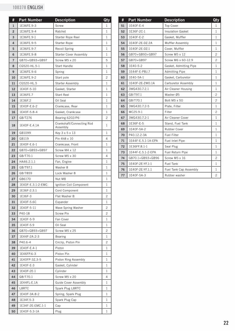
22
100378 ENGLISHEngine Parts List
# Part Number Description Qty1 1E36FE.9-3 Screw 1
2 1E36FE.9-4 Ratchet 1
3 1E36FE.9-1 Starter Rope Reel 1
4 1E36FE.9-5 Starter Rope 1
5 1E36FE.9-7 Recoil Spring 1
6 1E36FE.9-8 Starter Cover Assembly 1
7 GB70+GB93+GB97 Screw M5 x 20 5
8 CG520-HL.5-1 Start Handle 1
9 1E36FE.9-6 Spring 1
10 1E36FE.9-2 Start pole 2
11 CG520-HL.5 Starter Assembly 1
12 1E40F-5-10 Gasket, Starter 1
13 1E36FE.7 Start Reel 1
14 1E36F.2 Oil Seal 1
15 1E40F-E.6-2 Crankcase, Rear 1
16 1E40F-5.8-4 Gasket, Crankcase 1
17 GB/T276 Bearing 6202/P6 2
18 1E40F-E.4.1A Crankshaft/Connecting Rod Assembly 1
19 GB1099 Key 3 x 5 x 13 1
20 GB119 Pin 4h8 x 10 4
21 1E40F-E.6-1 Crankcase, Front 1
22 GB70+GB93+GB97 Screw M4 x 12 1
23 GB/T70.1 Screw M5 x 30 4
24 HA46.2.1.1 Fan, Engine 1
25 GB/T97.1 Washer 8 1
26 GB/T859 Lock Washer 8 1
27 GB6170 Nut M8 1
28 1E40F-E.3.1-2-EMC Ignition Coil Component 1
29 1E36F-2.3.1 Cord Component 1
30 1E36F-3 Flat Washer B 2
31 1E40F-5.6C Expander 1
32 1E40F-5-11 Wave Spring Washer 2
33 P40-18 Screw Pin 2
34 1E40F-5-9 Fan Cover 1
35 1E40F-5.9 Oil Seal 1
36 GB70+GB93+GB97 Screw M5 x 25 2
37 1E44F-2A.2-3 Bearing 1
38 P40.6-4 Circlip, Piston Pin 2
39 1E40F-E.4-1 Piston 1
40 1E46FP.6-3 Piston Pin 1
41 1E40FP-3Z.3-5 Piston Ring Assembly 1
42 1E40F-E-3 Gasket, Cylinder 1
43 1E40F-2E-1 Cylinder 1
44 GB/T70.1 Screw M5 x 20 4
45 1E44FL-E.1A Guide Cover Assembly 1
46 L8RTC Spark Plug L8RTC 1
47 1E40F-3A.8-2 Spring, Spark Plug 1
48 1E34F.5-3 Spark Plug Cap 1
49 1E34F-2E-EMC.1-1 Cap 1
50 1E40F-5.3-1A Plug 1
# Part Number Description Qty51 1E40F-E-4 Top Cover 1
52 1E36F-2C-1 Insulation Gasket 1
53 1E40F-E-2 Gasket, Muffler 1
54 1E40F-2E-DZ.2A Muffler Assembly 1
55 1E40F-2E-DZ-1 Cover, Muffler 1
56 GB70+GB93+GB97 Screw M5 x 12 2
57 GB70+GB97 Screw M6 x 60-12.9 2
58 1E40-5-2 Gasket, Admitting Pipe 1
59 1E44F-E-PBJ.7 Admitting Pipe 1
60 1E40-5A-1 Gasket, Carburetor 1
61 1E40F-2E-ZWO.1A Carburetor Assembly 1
62 3WG430.7.2.1 Air Cleaner Housing 1
63 GB/T97.1 Washer Ø5 2
64 GB/T70.1 Bolt M5 x 50 2
65 3WG430.7.2-5 Plate, Filter 1
66 MC25.9-1 Filter 2
67 3WG430.7.2-1 Air Cleaner Cover 1
68 1E36F-E-5 Stand, Fuel Tank 1
69 1E40F-5A-2 Rubber Cover 1
70 P40.12.2-3A Fuel Filter 1
71 1E44F-E.5.1-1A-EPA Fuel Inlet Pipe 1
72 1E36FF.8.1-1 Seal Plug 1
73 1E44F-E.5.1-2-EPA Fuel Return Pipe 1
74 GB70.1+GB93+GB96 Screw M5 x 16 2
75 1E40F-2E-YF.1-1 Fuel Tank 1
76 1E40F-2E-YF.1.1 Fuel Tank Cap Assembly 1
77 1E40F-5A-3 Rubber washer 2

WARRANTY*CHAMPION POWER EQUIPMENT
2 YEAR LIMITED WARRANTY
Warranty QualificationsTo register your product for warranty and FREE lifetime call center technical support please visit:
https://www.championpowerequipment.com/register
To complete registration you will need to include a copy of the purchase receipt as proof of original purchase. Proof of purchase is required for warranty service. Please register within ten (10) days from date of purchase.
Repair/Replacement WarrantyCPE warrants to the original purchaser that the mechanical and electrical components will be free of defects in material and workmanship for a period of two years (parts and labor) from the original date of purchase. Transportation charges on product submitted for repair or replacement under this warranty are the sole responsibility of the purchaser. This warranty only applies to the original purchaser and is not transferable.
Do Not Return The Unit To The Place Of PurchaseContact CPE’s Technical Service and CPE will troubleshoot any issue via phone or e-mail. If the problem is not corrected by this method, CPE will, at its option, authorize evaluation, repair or replacement of the defective part or component at a CPE Service Center. CPE will provide you with a case number for warranty service. Please keep it for future reference. Repairs or replacements without prior authorization, or at an unauthorized repair facility, will not be covered by this warranty.
Warranty ExclusionsThis warranty does not cover the following:
Normal Wear
Products with mechanical and electrical components need periodic parts and service to perform well. This warranty does not cover repair when normal use has exhausted the life of a part or the equipment as a whole.
Installation, Use and Maintenance
This warranty will not apply to parts and/or labor if the product is deemed to have been misused, neglected, involved in an accident, abused, loaded beyond the product’s limits or modified. Normal maintenance is not covered by this warranty and is not required to be performed at a facility or by a person authorized by CPE.
Other ExclusionsThis warranty excludes:
– Cosmetic defects such as paint, decals, etc.
– Wear items such as filter elements, o-rings, etc.
– Failures due to acts of God and other force majeure events beyond the manufacturer’s control.
– Problems caused by parts that are not original Champion Power Equipment parts.
Limits of Implied Warranty and Consequential DamageChampion Power Equipment disclaims any obligation to cover any loss of time, use of this product, freight, or any incidental or consequential claim by anyone from using this product. THIS WARRANTY AND THE ATTACHED U.S. EPA and/or CARB EMISSION CONTROL SYSTEM WARRANTIES (WHEN APPLICABLE) ARE IN LIEU OF ALL OTHER WARRANTIES, EXPRESS OR IMPLIED, INCLUDING WARRANTIES OF MERCHANTABILITY OR FITNESS FOR A PARTICULAR PURPOSE.
A unit provided as an exchange will be subject to the warranty of the original unit. The length of the warranty governing the exchanged unit will remain calculated by reference to the purchase date of the original unit.
This warranty gives you certain legal rights which may change from state to state or province to province. Your state or province may also have other rights you may be entitled to that are not listed within this warranty.
Contact InformationAddress
Champion Power Equipment, Inc. 12039 Smith Ave. Santa Fe Springs, CA 90670 USA www.championpowerequipment.com
Customer Service
Mon – Fri 8:30 AM – 5:00 PM (PST/PDT) Toll Free: 1-877-338-0999 [email protected] Fax no.: 1-562-236-9429
Technical Service
Mon – Fri 8:30 AM – 5:00 PM (PST/PDT) Toll Free: 1-877-338-0999 [email protected] 24/7 Tech Support: 1-562-204-1188
*Except as otherwise stipulated in any of the following enclosed Emission Control System Warranties (when applicable) for the Emission Control System: U.S. Environment Protection Agency (EPA) and/or California Air Resources Board (CARB).

Your Champion Power Equipment (CPE) engine complies with U.S. EPA emission regulations.
YOUR WARRANTY RIGHTS AND OBLIGATIONS:The US EPA AND CPE are pleased to explain the Federal Emission Control Systems Warranty on your 2019 small off-road engine (SORE) and engine powered equipment. New engines and equipment must be designed, built and equipped, at the time of sale, to meet U.S. EPA regulations for small off-road engines (SORE). CPE warrants the emission control system on your small off-road engine (SORE) and equipment for the period of time listed below, provided there has been no abuse, neglect, unapproved modification, or improper maintenance of your equipment.
Your emission control system may include parts such as the carburetor, fuel-injection system, the ignition system, catalytic converter and fuel lines. Also included may be hoses, belts, connectors and other emission related assemblies. Where a warrantable condition exits, CPE will repair your small off-road engine (SORE) at no cost to you including diagnosis, parts and labor.
MANUFACTURER’S EMISSION CONTROL SYSTEM WARRANTY COVERAGE:This emission control system is warranted for two years, subject to provisions set forth below. If, during the warranty period, an emission related part on your engine is defective in materials or workmanship, the part will be repaired or replaced by CPE.
OWNER WARRANTY RESPONSIBILITIES:As the small off-road engine (SORE) owner, you are responsible for the performance of the required maintenance listed in your Owner’s Manual. CPE recommends that you retain all your receipts covering maintenance on your small off-road engine (SORE), but CPE cannot deny warranty solely for the lack of receipts or for your failure to ensure the performance of all scheduled maintenance.
As the small off-road engine (SORE) owner, you should however be aware that CPE may deny you warranty coverage if your small, off-road engine (SORE) or a part has failed due to abuse, neglect, improper maintenance or unapproved modifications.
You are responsible for presenting your small off-road engine (SORE) to an Authorized CPE service outlet or alternate service outlet as described in (3)(f.) below, CPE dealer or CPE, Santa Fe Springs, Ca. as soon as a problem exists. The warranty repairs should be completed in a reasonable amount of time, not to exceed 30 days.
If you have any questions regarding your warranty rights and responsibilities, you should contact:
Champion Power Equipment, Inc. Customer Service 12039 Smith Ave.
Santa Fe Springs, CA 90670 1-877-338-0999
CHAMPION POWER EQUIPMENT, INC. (CPE), THE UNITED STATES ENVIRONMENT PROTECTION AGENCY (U.S. EPA)
EMISSION CONTROL SYSTEM WARRANTY

EMISSION CONTROL SYSTEM WARRANTYThe following are specific provisions relative to your Emission Control System (ECS) Warranty Coverage.
1. APPLICABILITY: This warranty shall apply to 1997 and later model year small off-road engines (SORE). The ECS Warranty Period shall begin on the date the new engine or equipment is delivered to its original, end-use purchaser, and shall continue for 24 consecutive months thereafter.
2. GENERAL EMISSIONS WARRANTY COVERAGE CPE warrants to the original, end-use purchaser of the new engine or equipment and to each subsequent purchaser that each of its small off-road engines (SORE) is:
2a. Designed, built and equipped so as to conform to U.S. EPA emissions standards for spark-ignited engines at or below 19 kilowatts.
2b. Free from defects in materials and workmanship that cause the failure of a warranted part to be identical in all material respects to the part as described in the engine manufacturer’s application for certification for a period of two years.
3. THE WARRANTY ON EMISSION-RELATED PARTS WILL BE INTERPRETED AS FOLLOWS:
3a. Any warranted part that is not scheduled for replacement as required maintenance in the Owners Manual shall be warranted for the ECS Warranty Period. If any such part fails during the ECS Warranty Period, it shall be repaired or replaced by CPE according to Subsection “d” below. Any such part repaired or replaced under the ECS Warranty shall be warranted for any remainder of the ECS Warranty Period.
3b. Any warranted, emissions-related part which is scheduled only for regular inspection as specified in the Owners Manual shall be warranted for the ECS Warranty Period. A statement in such written instructions to the effect of “repair or replace as necessary”, shall not reduce the ECS Warranty Period. Any such part repaired or replaced under the ECS Warranty shall be warranted for the remainder of the ECS Warranty Period.
3c. Any warranted, emissions-related part which is scheduled for replacement as required maintenance in the Owner’s Manual shall be warranted for the period of time prior to the first scheduled replacement point for that part. If the part fails prior to the first scheduled replacement, the part shall be repaired or replaced by CPE according to Subsection “d” below. Any such emissions-related part repaired or replaced under the ECS Warranty, shall be warranted for the remainder of the ECS Warranty Period prior to the first scheduled replacement point for such emissions-related part.
3d. Repair or replacement of any warranted, emissions-related part under this ECS Warranty shall be performed at no charge to the owner at a CPE Authorized Service Outlet.
3e. The owner shall not be charged for diagnostic labor which leads to the determination that a part covered by the ECS Warranty is in fact defective, provided that such diagnostic work is performed at a CPE Authorized Service Outlet.
3f. CPE shall pay for covered emissions warranty repairs at non-authorized service outlets under the following circumstances:
i. The service is required in a population center with a population over 100,000 according to U.S. Census 2000 without a CPE Authorized Service Outlet AND
ii. The service is required more than 100 miles from a CPE Authorized Service Outlet. The 100 mile limitation does not apply in the following states: Alaska, Arizona, Colorado, Hawaii, Idaho, Montana, Nebraska, Nevada, New Mexico, Oregon, Texas, Utah and Wyoming.
3g. CPE shall be liable for damages to other original engine components or approved modifications proximately caused by a failure under warranty of an emission-related part covered by the ECS Warranty.
3h. Throughout the ECS Warranty Period, CPE shall maintain a supply of warranted emission-related parts sufficient to meet the expected demand for such emission-related parts.
3i. Any CPE Authorized and approved emission-related replacement part may be used in the performance of any ECS Warranty maintenance or repair and will be provided without charge to the owner. Such use shall not reduce CPE’s warranty obligation.
3j. Unapproved add-on or modified parts may not be used to modify or repair a CPE engine. Such use voids this ECS Warranty and shall be sufficient grounds for disallowing an ECS Warranty claim. CPE shall not be liable hereunder for failures of any warranted parts of a CPE engine caused by the use of such an unapproved add-on or modified part.

EMISSION-RELATED PARTS INCLUDE THE FOLLOWING: (using those portions of the list applicable to the engine)
Systems covered by this warranty
Parts Description
Fuel Metering System Fuel regulator, Carburetor and internal parts
Air Induction System Air cleaner, Intake manifold
Ignition System Spark plug and parts, Magneto ignition system
Exhaust System Exhaust manifold, catalytic converter
Miscellaneous Parts Tubing, Fittings, Seals, Gaskets, and Clamps associated with these listed systems.
Evaporative Emissions Fuel Tank, Fuel Cap, Fuel Line (for liquid fuel and fuel vapors), Fuel Line Fittings, Clamps, Pressure Relief Valves, Control Valves, Control Solenoids, Electronic Controls, Vacuum Control Diaphragms, Control Cables, Control Linkages, Purge Valves, Gaskets, Vapor Hoses, Liquid/Vapor Separator, Carbon Canister, Canister Mounting Brackets, Carburetor Purge Port Connector
TO OBTAIN WARRANTY SERVICE:You must take your CPE engine or the product on which it is installed, along with your warranty registration card or other proof of original purchase date, at your expense, to any Champion Power Equipment dealer who is authorized by Champion Power Equipment, Inc. to sell and service that CPE product during his normal business hours. Alternate service locations defined in Section (3)(f.) above must be approved by CPE prior to service. Claims for repair or adjustment found to be caused solely by defects in material or workmanship will not be denied because the engine was not properly maintained and used.
If you have any questions regarding your warranty rights and responsibilities, or to obtain warranty service, please write or call Customer Service at Champion Power Equipment, Inc.
Champion Power Equipment, Inc. 12039 Smith Ave.
Santa Fe Springs, CA 90670 1-877-338-0999
Attn.: Customer Service [email protected]