Cubimorph: Designing Modular Interactive Devices · mechanism to self-reconfigure in the user’s...
7
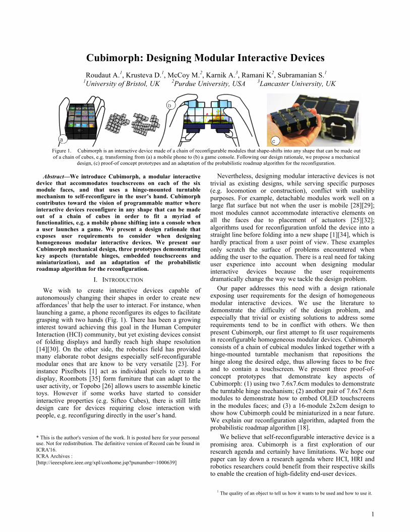
1 Abstract—We introduce Cubimorph, a modular interactive device that accommodates touchscreens on each of the six module faces, and that uses a hinge-mounted turntable mechanism to self-reconfigure in the user’s hand. Cubimorph contributes toward the vision of programmable matter where interactive devices reconfigure in any shape that can be made out of a chain of cubes in order to fit a myriad of functionalities, e.g. a mobile phone shifting into a console when a user launches a game. We present a design rationale that exposes user requirements to consider when designing homogeneous modular interactive devices. We present our Cubimorph mechanical design, three prototypes demonstrating key aspects (turntable hinges, embedded touchscreens and miniaturization), and an adaptation of the probabilistic roadmap algorithm for the reconfiguration. I. INTRODUCTION We wish to create interactive devices capable of autonomously changing their shapes in order to create new affordances 1 that help the user to interact. For instance, when launching a game, a phone reconfigures its edges to facilitate grasping with two hands (Fig. 1). There has been a growing interest toward achieving this goal in the Human Computer Interaction (HCI) community, but yet existing devices consist of folding displays and hardly reach high shape resolution [14][30]. On the other side, the robotics field has provided many elaborate robot designs especially self-reconfigurable modular ones that are know to be very versatile [23]. For instance Pixelbots [1] act as individual pixels to create a display, Roombots [35] form furniture that can adapt to the user activity, or Topobo [26] allows users to assemble kinetic toys. However if some works have started to consider interactive properties (e.g. Sifteo Cubes), there is still little design care for devices requiring close interaction with people, e.g. reconfiguring directly in the user’s hand. * This is the author's version of the work. It is posted here for your personal use. Not for redistribution. The definitive version of Record can be found in ICRA'16. ICRA Archives : [http://ieeexplore.ieee.org/xpl/conhome.jsp?punumber=1000639] Nevertheless, designing modular interactive devices is not trivial as existing designs, while serving specific purposes (e.g. locomotion or construction), conflict with usability purposes. For example, detachable modules work well on a large flat surface but not when the user is mobile [28][29]; most modules cannot accommodate interactive elements on all the faces due to placement of actuators [25][32]; algorithms used for reconfiguration unfold the device into a straight line before folding into a new shape [1][34], which is hardly practical from a user point of view. These examples only scratch the surface of problems encountered when adding the user to the equation. There is a real need for taking user experience into account when designing modular interactive devices because the user requirements dramatically change the way we tackle the design problem. Our paper addresses this need with a design rationale exposing user requirements for the design of homogeneous modular interactive devices. We use the literature to demonstrate the difficulty of the design problem, and especially that trivial or existing solutions to address some requirements tend to be in conflict with others. We then present Cubimorph, our first attempt to fit user requirements in reconfigurable homogeneous modular devices. Cubimorph consists of a chain of cubical modules linked together with a hinge-mounted turntable mechanism that repositions the hinge along the desired edge, thus allowing faces to be free and to contain a touchscreen. We present three proof-of- concept prototypes that demonstrate key aspects of Cubimorph: (1) using two 7.6x7.6cm modules to demonstrate the turntable hinge mechanism; (2) another pair of 7.6x7.6cm modules to demonstrate how to embed OLED touchscreens in the modules faces; and (3) a 16-module 2x2cm design to show how Cubimorph could be miniaturized in a near future. We explain our reconfiguration algorithm, adapted from the probabilistic roadmap algorithm [18]. 1 We believe that self-reconfigurable interactive device is a promising area. Cubimorph is a first exploration of our research agenda and certainly have limitations. We hope our paper can lay down a research agenda where HCI, HRI and robotics researchers could benefit from their respective skills to enable the creation of high-fidelity end-user devices. 1 The quality of an object to tell us how it wants to be used and how to use it. Cubimorph: Designing Modular Interactive Devices Roudaut A. 1 , Krusteva D. 1 , McCoy M. 2 , Karnik A. 3 , Ramani K 2 , Subramanian S. 1 1 University of Bristol, UK 2 Purdue University, USA 3 Lancaster University, UK Figure 1. Cubimorph is an interactive device made of a chain of reconfigurable modules that shape-shifts into any shape that can be made out of a chain of cubes, e.g. transforming from (a) a mobile phone to (b) a game console. Following our design rationale, we propose a mechanical design, (c) proof-of concept prototypes and an adaptation of the probabilistic roadmap algorithm for the reconfiguration.
Transcript of Cubimorph: Designing Modular Interactive Devices · mechanism to self-reconfigure in the user’s...
1
Abstract—We introduce Cubimorph, a modular interactive device that accommodates touchscreens on each of the six module faces, and that uses a hinge-mounted turntable mechanism to self-reconfigure in the user’s hand. Cubimorph contributes toward the vision of programmable matter where interactive devices reconfigure in any shape that can be made out of a chain of cubes in order to fit a myriad of functionalities, e.g. a mobile phone shifting into a console when a user launches a game. We present a design rationale that exposes user requirements to consider when designing homogeneous modular interactive devices. We present our Cubimorph mechanical design, three prototypes demonstrating key aspects (turntable hinges, embedded touchscreens and miniaturization), and an adaptation of the probabilistic roadmap algorithm for the reconfiguration.
I. INTRODUCTION We wish to create interactive devices capable of
autonomously changing their shapes in order to create new affordances1 that help the user to interact. For instance, when launching a game, a phone reconfigures its edges to facilitate grasping with two hands (Fig. 1). There has been a growing interest toward achieving this goal in the Human Computer Interaction (HCI) community, but yet existing devices consist of folding displays and hardly reach high shape resolution [14][30]. On the other side, the robotics field has provided many elaborate robot designs especially self-reconfigurable modular ones that are know to be very versatile [23]. For instance Pixelbots [1] act as individual pixels to create a display, Roombots [35] form furniture that can adapt to the user activity, or Topobo [26] allows users to assemble kinetic toys. However if some works have started to consider interactive properties (e.g. Sifteo Cubes), there is still little design care for devices requiring close interaction with people, e.g. reconfiguring directly in the user’s hand.
* This is the author's version of the work. It is posted here for your personaluse. Not for redistribution. The definitive version of Record can be found inICRA'16.ICRA Archives :[http://ieeexplore.ieee.org/xpl/conhome.jsp?punumber=1000639]
Nevertheless, designing modular interactive devices is not trivial as existing designs, while serving specific purposes (e.g. locomotion or construction), conflict with usability purposes. For example, detachable modules work well on a large flat surface but not when the user is mobile [28][29]; most modules cannot accommodate interactive elements on all the faces due to placement of actuators [25][32]; algorithms used for reconfiguration unfold the device into a straight line before folding into a new shape [1][34], which is hardly practical from a user point of view. These examples only scratch the surface of problems encountered when adding the user to the equation. There is a real need for taking user experience into account when designing modular interactive devices because the user requirements dramatically change the way we tackle the design problem.
Our paper addresses this need with a design rationale exposing user requirements for the design of homogeneous modular interactive devices. We use the literature to demonstrate the difficulty of the design problem, and especially that trivial or existing solutions to address some requirements tend to be in conflict with others. We then present Cubimorph, our first attempt to fit user requirements in reconfigurable homogeneous modular devices. Cubimorph consists of a chain of cubical modules linked together with a hinge-mounted turntable mechanism that repositions the hinge along the desired edge, thus allowing faces to be free and to contain a touchscreen. We present three proof-of-concept prototypes that demonstrate key aspects of Cubimorph: (1) using two 7.6x7.6cm modules to demonstrate the turntable hinge mechanism; (2) another pair of 7.6x7.6cm modules to demonstrate how to embed OLED touchscreens in the modules faces; and (3) a 16-module 2x2cm design to show how Cubimorph could be miniaturized in a near future. We explain our reconfiguration algorithm, adapted from the probabilistic roadmap algorithm [18].1
We believe that self-reconfigurable interactive device is a promising area. Cubimorph is a first exploration of our research agenda and certainly have limitations. We hope our paper can lay down a research agenda where HCI, HRI and robotics researchers could benefit from their respective skills to enable the creation of high-fidelity end-user devices.
1 The quality of an object to tell us how it wants to be used and how to use it.
Cubimorph: Designing Modular Interactive Devices Roudaut A.1, Krusteva D.1, McCoy M.2, Karnik A.3, Ramani K2, Subramanian S.1
1University of Bristol, UK
2Purdue University, USA 3Lancaster University, UK
Figure 1. Cubimorph is an interactive device made of a chain of reconfigurable modules that shape-shifts into any shape that can be made out of a chain of cubes, e.g. transforming from (a) a mobile phone to (b) a game console. Following our design rationale, we propose a mechanical
design, (c) proof-of concept prototypes and an adaptation of the probabilistic roadmap algorithm for the reconfiguration.
2
II. DESIGN RATIONALE
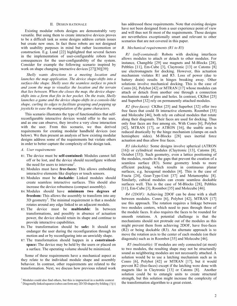
Existing modular robots designs are demonstrably very versatile. But using them to create interactive devices proves to be a difficult task as some designs address certain issues but create new ones. In fact these robots are not designed with usability purposes in mind but rather locomotion or construction. E.g. Lund [22] highlighted that several factors in the implementation of user-configurable robots have consequences for the user-configurability of the system. Consider for example the following scenario inspired by work on shape changing interactive devices [27][30][39]:
Shelly wants directions to a meeting location and launches the map application. The device shape-shifts into a surface-like shape. Shelly uses the seamless surface to pinch and zoom the map to visualize the location and the terrain that lies between. When she closes the map, the device shape-shifts into a form that fits in her pocket. On the train, Shelly launches a game and the device shape-shifts in a console-like shape, curling its edges to facilitate grasping and popping up joysticks to ease the manipulation of the game characters.
This scenario illustrates the type of functionalities that self-reconfigurable interactive devices would offer to the user, and as one can observe, they involve a very close interaction with the user. From this scenario, we thus derived requirements for creating modular handheld devices (see below). We then present an analysis of how existing modular designs address some of the requirements but violate others in order to better capture the complexity of the design task. A. User requirements R1. The device must be self-contained: Modules cannot fall
off or be lost, and the device should reconfigure without the need for users to intervene2.
R2. Modules must have free-faces: This allows embedding interactive elements like displays or touch sensors.
R3. Modules must be dockable: Linked modules should create seamless interactive surfaces. This should also increase the device robustness (compact assembly).
R4. Modules should have minimum two degrees of freedom: This allows the assembly to transform into any 3D geometry3. The minimal requirement is that a module rotates around any edge linked to an adjacent module.
R5. The device must be multistable: In between transformations, and possibly in absence of actuation power, the device should retain its shape and continue to provide interactive capabilities.
R6. The transformation should be safe: It should not endanger the user during the reconfiguration through its motion and or by reconfiguring into an unwieldy shape.
R7. The transformation should happen in a constrained-space: The device may be held by the users or placed on a surface. The operating volume should be minimized.
Some of these requirements have a mechanical aspect as they relate to the individual module shape and assembly behavior. In contrast, other requirements are related to the transformation. Next, we discuss how previous related work
2 Modules could also find others, but this is impractical in a mobile context 3 Diagonally linked squares/cubes can form any 2D/3D shapes by folding [7][1]
has addressed these requirements. Note that existing designs have not been designed from a user experience point of view and will thus not fit most of the requirements. Those designs are nevertheless exceptionally smart and relevant to other scenarios that are not covered in this paper.
B. Mechanical requirements (R1 to R5)
R1 (self-contained): Robots with docking interfaces allows modules to attach or detach to other modules. For instance, Changible [29] use magnets and M-Blocks [28], Pebbles [11], Em-Cube [3], Claytronic [13] or Catoms [8] use electromagnets for docking. However, this actuation mechanism violates R1 and R5. Loss of power (due to battery drain) results in hinges breaking away. Other solutions involve mechanical docking. This is the case of Conro [6], Polybot [42] or MTRAN [17] whose modules can attach or detach from another one through a connection mechanism made of pins and holes. In contrast, CKBot [25] and Superbot [32] rely on permanently attached modules.
R2 (free-faces): CKBot [25] and Superbot [32] offer two free faces that could fit interactive elements. Roombot [35] and Molecube [46], both rely on cubical modules that rotate along their diagonals. Their faces are used for docking. Thus only four faces are free among six. With Conro [6], Polybot [42], MTRAN [17], or ATRON [16], the usable area is reduced drastically by the hinge mechanism (clamps on each hemisphere sides). M-Blocks [28] uses inertial force actuation and thus allow free faces.
R3 (dockable): Some designs involve spherical (ATRON [16]) or cylindrical modules (Claytronic [13], Catoms [8], Octabot [33]). Such geometry, even a lattice positioning of the modules, results in the gaps that prevent the creation of a seamless surface (R3). Some geometry lends to more efficient packing, which results in continuous planar surfaces, e.g. hexagonal modules [4]. This is the case of Fracta [24], Gear-Type-Unit [37] and Metamorphic [8]. Similarly, cubical modules can create seamless dockable surfaces well. This is the case of M-Blocks [28], Pebbles [11], Em-Cube [3], Roombot [35] and Molecube [46].
R4 (2DOF): Achieving 2DOF can be done with a shaft between modules. Conro [6], Polybot [42], MTRAN [17] use this approach. The rotation requires a linkage between two modules centers, which need to pass through three of the module faces. It also requires the faces to be rounded for smooth rotations. A potential challenge is that the mechanisms should not protrude out of the modules as this might prevent them from achieving 2DOF, have free-faces (R2) or being dockable (R3). An alternate approach is to move the rotation axis to the center of each module (on their diagonals) such as in Roombot [35] and Molecube [46].
R5 (multistable): If modules are only connected (at most) to two modules, the resulting shape may not be structurally sound as neighboring modules are not necessarily attached. A solution would be to use a latching mechanism such as in Conro [6], Polybot [42] or MTRAN [17], but it would prevent R2 (free-faces) except if the latching were done with magnets like in Claytronic [13] or Catoms [8]. Another solution could be to entangle units to create structural strength, but this solution might increase the complexity of the transformation algorithm to a great extent.
3
C. Transformation requirements (R6, R7)
R6 (safety): Existing algorithms can transform a chain into another while avoiding collisions with or without obstacles ([21][41]). Obstacles could the user’s hand or the other users in proximity. In Yakey et al. [41], however, the links between modules are reduced to points and are allowed to pass through each other, and thus it does not model constraints of the real world. Adding such constraints significantly impacts the complexity of the algorithms as reported by Trinkle et al. [38]. Meanwhile, some researchers have proposed solutions for discrete motion planning with obstacles but it is still considered to be a difficult problem, especially when the numbers of modules is increasing [5][31].
R7 (constrained-space): Most algorithms do not take into consideration a constrained space and are specific to some design such as MTRAN [44] Pebbles [12] or Catoms-like structures using hexagonal modules [43] [40]. More generic algorithms such as Motein [34], protein-folding algorithm [1] or 2D chaining [31], also fail to validate this requirement as they rely on applying repulsive forces to unfold the chain and thus generally tend undergo a fully unfolded phase (all modules in a straight line). A solution is to consider the problem of constrained space as a particular form of reconfiguring with dynamic obstacles such as in [9], but this algorithm is specific to locomotion planning for cranes.
III. CUBIMORPH MECHANICAL DESIGN AND PROTOTYPES
Cubimorph mechanical design is a first attempt to satisfy R1, R2, R3, R4 and R5. A. Principle
Cubimorph design (Fig. 2) allows rotation along the edges of each module using reconfigurable hinges which keep the modules connected at all time. This lets all module faces free to accommodate touchscreens.
Figure 2. Cubimorph mechanical design overview. A chain of modules (R1): Cubimorph is a homogeneous
chain of cubical modules. Modules have five possible positions relatively to their neighbor: straight, top, bottom, back or front. Relying on independent hinges per edge requires complex docking interfaces and does not fully answer R1. We eliminate this need by using a single actuated hinge, which keeps the modules connected at all time.
Modules shape (R2, R3): Each module is cubical, thus enabling the placement of interactive elements as well as allowing seamless docking.
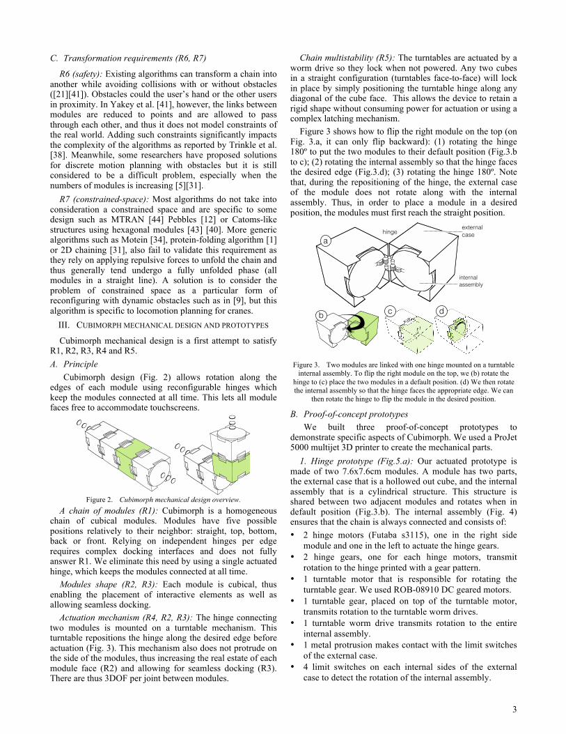
Actuation mechanism (R4, R2, R3): The hinge connecting two modules is mounted on a turntable mechanism. This turntable repositions the hinge along the desired edge before actuation (Fig. 3). This mechanism also does not protrude on the side of the modules, thus increasing the real estate of each module face (R2) and allowing for seamless docking (R3). There are thus 3DOF per joint between modules.
Chain multistability (R5): The turntables are actuated by a worm drive so they lock when not powered. Any two cubes in a straight configuration (turntables face-to-face) will lock in place by simply positioning the turntable hinge along any diagonal of the cube face. This allows the device to retain a rigid shape without consuming power for actuation or using a complex latching mechanism.
Figure 3 shows how to flip the right module on the top (on Fig. 3.a, it can only flip backward): (1) rotating the hinge 180º to put the two modules to their default position (Fig.3.b to c); (2) rotating the internal assembly so that the hinge faces the desired edge (Fig.3.d); (3) rotating the hinge 180º. Note that, during the repositioning of the hinge, the external case of the module does not rotate along with the internal assembly. Thus, in order to place a module in a desired position, the modules must first reach the straight position.
Figure 3. Two modules are linked with one hinge mounted on a turntable internal assembly. To flip the right module on the top, we (b) rotate the
hinge to (c) place the two modules in a default position. (d) We then rotate the internal assembly so that the hinge faces the appropriate edge. We can
then rotate the hinge to flip the module in the desired position.
B. Proof-of-concept prototypes We built three proof-of-concept prototypes to
demonstrate specific aspects of Cubimorph. We used a ProJet 5000 multijet 3D printer to create the mechanical parts.
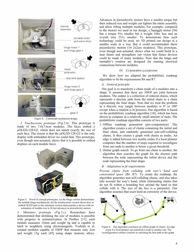
1. Hinge prototype (Fig.5.a): Our actuated prototype ismade of two 7.6x7.6cm modules. A module has two parts, the external case that is a hollowed out cube, and the internal assembly that is a cylindrical structure. This structure is shared between two adjacent modules and rotates when in default position (Fig.3.b). The internal assembly (Fig. 4) ensures that the chain is always connected and consists of: • 2 hinge motors (Futaba s3115), one in the right side
module and one in the left to actuate the hinge gears.• 2 hinge gears, one for each hinge motors, transmit
rotation to the hinge printed with a gear pattern.• 1 turntable motor that is responsible for rotating the
turntable gear. We used ROB-08910 DC geared motors.• 1 turntable gear, placed on top of the turntable motor,
transmits rotation to the turntable worm drives.• 1 turntable worm drive transmits rotation to the entire
internal assembly.• 1 metal protrusion makes contact with the limit switches
of the external case.• 4 limit switches on each internal sides of the external
case to detect the rotation of the internal assembly.
b c d
a external case hinge
internal assembly
4
Figure 4. Cubimorph mechanical design.
2. Touchscreens prototype (Fig.5.b): This prototype ismade of two 7.6x7.6cm modules. The faces embed a µOLED-128-G2, which does not match exactly the size of each face. The reason is that the µOLED-128-G2 is the only display with embedded driver we could find. This prototype, even though non-actuated, shows that it is possible to embed displays on each module faces.
Figure 5. Proof-of concept prototypes: (a) the hinge version demonstrates the turtable hinge mechanicsm; (b) the touchscreens version shows how to embed OLED and (c) the miniature version demonstrates a device with an
estimation of module size to fit last advances in piezoelectric motors.
3. Miniature prototype (Fig.5.c): Researchers havedemonstrated that shrinking the size of modules is possible with progress in miniaturization. In Peebles [11], each module measures 12mm and weight 4g and is capable to latch to neighbors using electromagnets. Yoshida et al. created modules capable of 1DOF that measure only 2cm and weight 15g each [45] using shape memory alloys.
Advances in piezoelectric motors have a smaller torque but their reduced size and weight can lighten the entire assembly and allow lifting multiple modules. For example, compared to the motors we used in our design, a Squiggle motor [36] has a torque 91x smaller but a weight 106x less and an overall area 231x smaller. To demonstrate how such technology could be used, we 3D printed our design at a smaller scale in a way that it could accommodate these piezoelectric motors (16 2x2cm modules). This prototype, even though non-actuated, shows what we could build in a near future and strengthens our vision that future devices could be made of many modules. Note that the hinge and turntable’s rotation are designed for running electrical connections between modules.
IV. CUBIMORPH ALGORITHM
We show how we adapted the probabilistic roadmap algorithm to fit the requirements R6 and R7.
A. General principle Our goal is to transform a chain made of n modules into a
shape. It assumes that there are 3DOF per joint between modules. The output is a collection of ordered chains, which represents a discrete path from the initial chain to a chain representing the final shape. Note that we treat the problem in a discrete way (angle between modules is 0º or 180º except when a rotation is in process). Our algorithm is based on the probabilistic roadmap algorithm [18], which has been shown to compute in a relatively small amount of steps. The probabilistic roadmap algorithm consists of two parts: 1. Offline roadmap generation (pre-computation): The
algorithm creates a set of chains containing the initial andfinal chain, and randomly generated non-self-collidingchains. It then creates a graph with chains as nodes. Anedge is added between two nearby nodes if a local plannercomputes that the number of steps required to reconfigurefrom one node to another is below a given threshold.
2. Online graph search: To go from one chain to another, thealgorithm then searches the graph for the shortest pathbetween the node representing the initial device and thenode representing the final shape.
B. Adaptation to fit requirements Prevent chains from colliding with user’s hand and constrained space (R6, R7): To create the roadmap, the algorithm generates non-self-colliding chains, and also takes into account the user’s hand, while eliminating chains that do not fit within a bounding box around the hand or that collide with it. The size of the box is a parameter. Our algorithm assumes that users hold an extremity of the device.
Figure 6. Our algorithm constructs an offline graph of chains. An edge exists if a local planner can transform a node to another one. The
reconfiguration (online) consists in searching the best path in the graph.
internal assembly
turnable motor and worm drive
one limit switch
metal protrusion
hinge motor 1 and hinge gear 1
hinge motor 2 and hinge gear 2
gear 1
gear 2
5
Detecting nearby chains: As with the original algorithm, we check for an edge between two nodes only if those nodes are nearby. This is computed using the number of rotations needed to go from one node to another (as a maximum threshold parameter of the algorithm). To compute this difference, we encode our chains as a vector of position (1 straight, 2 top, 3 bottom, 4 back, 5 front) that represents the relative position of each module to its previous neighbor. For example a straight chain of 5 modules with the last module placed on the bottom of the previous one is {1,1,1,3}. The difference between two vectors tells how many rotations are needed to go from the first chain to the other one and thus decide if the chains are nearby.
The local planner checks user’s hand collision and allows constrained space to inflate (R6, R7): To transform a node into another, the local planer rotates each module one by one in its correct position, thus creating a sequence of chains that represent the path between one chain to another. This simple planner computes in a constrained space. It means that each time a collision is detected with the bounding box or the user’s hand, the algorithm first resolves it. For example when rotating the middle of a chain, if the last module collides with the hand, the algorithm first rotates the colliding module so that its new position will not create a collision when performing the original rotation. As resolving a collision can lead to collisions, the planner uses recursive calls. If the algorithm fails to compute efficiently (the number of reconfigurations in recursion reaches a certain threshold), the bounding box of the constrained space increases and the planner starts again, or abandons the path if the box size reaches a given threshold. Each edge is tagged with a tuple: This tuple corresponds to the output properties of the local planner that consist of the number of reconfigurations necessary, the torque required, and the area of the bounding box used to perform the reconfiguration.
Parametrizable path search (R7): The algorithm can search the shortest path (Dijkstra) in the graph but also take into account the parameters of each edges. E.g. one could tradeoff number of steps over space. The algorithm can also be parameterized so that the search produces a path that fits the maximum torque that the design permits.
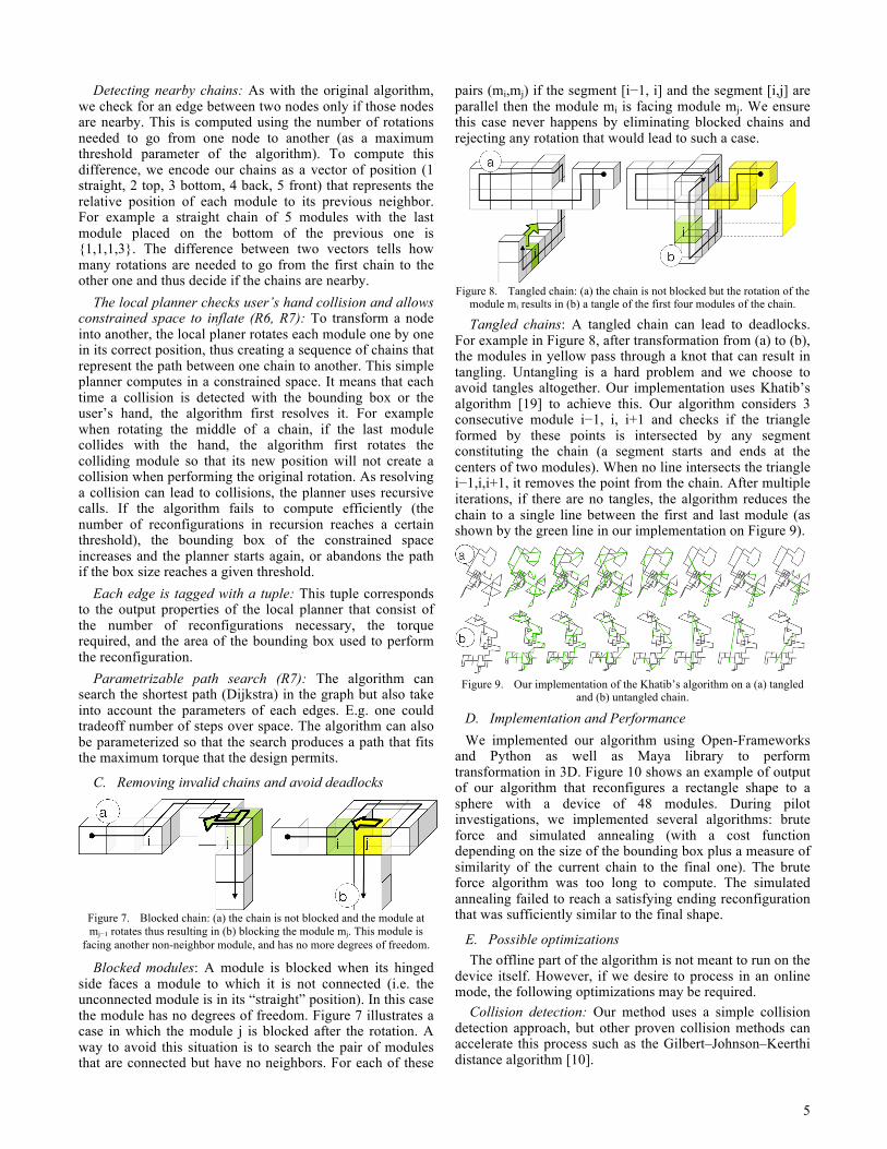
C. Removing invalid chains and avoid deadlocks
Figure 7. Blocked chain: (a) the chain is not blocked and the module at mj−1 rotates thus resulting in (b) blocking the module mj. This module is
facing another non-neighbor module, and has no more degrees of freedom.
Blocked modules: A module is blocked when its hinged side faces a module to which it is not connected (i.e. the unconnected module is in its “straight” position). In this case the module has no degrees of freedom. Figure 7 illustrates a case in which the module j is blocked after the rotation. A way to avoid this situation is to search the pair of modules that are connected but have no neighbors. For each of these
pairs (mi,mj) if the segment [i−1, i] and the segment [i,j] are parallel then the module mi is facing module mj. We ensure this case never happens by eliminating blocked chains and rejecting any rotation that would lead to such a case.
Figure 8. Tangled chain: (a) the chain is not blocked but the rotation of the
module mi results in (b) a tangle of the first four modules of the chain.
Tangled chains: A tangled chain can lead to deadlocks. For example in Figure 8, after transformation from (a) to (b), the modules in yellow pass through a knot that can result in tangling. Untangling is a hard problem and we choose to avoid tangles altogether. Our implementation uses Khatib’s algorithm [19] to achieve this. Our algorithm considers 3 consecutive module i−1, i, i+1 and checks if the triangle formed by these points is intersected by any segment constituting the chain (a segment starts and ends at the centers of two modules). When no line intersects the triangle i−1,i,i+1, it removes the point from the chain. After multiple iterations, if there are no tangles, the algorithm reduces the chain to a single line between the first and last module (as shown by the green line in our implementation on Figure 9).
Figure 9. Our implementation of the Khatib’s algorithm on a (a) tangled
and (b) untangled chain.
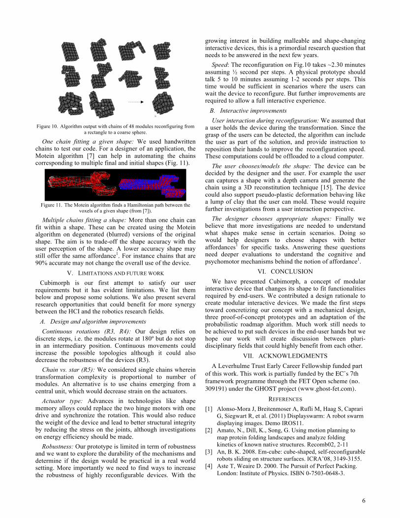
D. Implementation and Performance We implemented our algorithm using Open-Frameworks
and Python as well as Maya library to perform transformation in 3D. Figure 10 shows an example of output of our algorithm that reconfigures a rectangle shape to a sphere with a device of 48 modules. During pilot investigations, we implemented several algorithms: brute force and simulated annealing (with a cost function depending on the size of the bounding box plus a measure of similarity of the current chain to the final one). The brute force algorithm was too long to compute. The simulated annealing failed to reach a satisfying ending reconfiguration that was sufficiently similar to the final shape.
E. Possible optimizations The offline part of the algorithm is not meant to run on the
device itself. However, if we desire to process in an online mode, the following optimizations may be required.
Collision detection: Our method uses a simple collision detection approach, but other proven collision methods can accelerate this process such as the Gilbert–Johnson–Keerthi distance algorithm [10].
6
Figure 10. Algorithm output with chains of 48 modules reconfiguring from a rectangle to a coarse sphere.
One chain fitting a given shape: We used handwritten chains to test our code. For a designer of an application, the Motein algorithm [7] can help in automating the chains corresponding to multiple final and initial shapes (Fig. 11).
Figure 11. The Motein algorithm finds a Hamiltonian path between the voxels of a given shape (from [7]).
Multiple chains fitting a shape: More than one chain can fit within a shape. These can be created using the Motein algorithm on degenerated (blurred) versions of the original shape. The aim is to trade-off the shape accuracy with the user perception of the shape. A lower accuracy shape may still offer the same affordance1. For instance chains that are 90% accurate may not change the overall use of the device.
V. LIMITATIONS AND FUTURE WORK Cubimorph is our first attempt to satisfy our user
requirements but it has evident limitations. We list them below and propose some solutions. We also present several research opportunities that could benefit for more synergy between the HCI and the robotics research fields.
A. Design and algorithm improvements Continuous rotations (R3, R4): Our design relies on
discrete steps, i.e. the modules rotate at 180º but do not stop in an intermediary position. Continuous movements could increase the possible topologies although it could also decrease the robustness of the devices (R3).
Chain vs. star (R5): We considered single chains wherein transformation complexity is proportional to number of modules. An alternative is to use chains emerging from a central unit, which would decrease strain on the actuators.
Actuator type: Advances in technologies like shape memory alloys could replace the two hinge motors with one drive and synchronize the rotation. This would also reduce the weight of the device and lead to better structural integrity by reducing the stress on the joints, although investigations on energy efficiency should be made.
Robustness: Our prototype is limited in term of robustness and we want to explore the durability of the mechanisms and determine if the design would be practical in a real world setting. More importantly we need to find ways to increase the robustness of highly reconfigurable devices. With the
growing interest in building malleable and shape-changing interactive devices, this is a primordial research question that needs to be answered in the next few years.
Speed: The reconfiguration on Fig.10 takes ~2.30 minutes assuming ½ second per steps. A physical prototype should talk 5 to 10 minutes assuming 1-2 seconds per steps. This time would be sufficient in scenarios where the users can wait the device to reconfigure. But further improvements are required to allow a full interactive experience.
B. Interactive improvements User interaction during reconfiguration: We assumed that
a user holds the device during the transformation. Since the grasp of the users can be detected, the algorithm can include the user as part of the solution, and provide instruction to reposition their hands to improve the reconfiguration speed. These computations could be offloaded to a cloud computer.
The user chooses/models the shape: The device can be decided by the designer and the user. For example the user can captures a shape with a depth camera and generate the chain using a 3D reconstitution technique [15]. The device could also support pseudo-plastic deformation behaving like a lump of clay that the user can mold. These would require further investigations from a user interaction perspective.
The designer chooses appropriate shapes: Finally we believe that more investigations are needed to understand what shapes make sense in certain scenarios. Doing so would help designers to choose shapes with better affordances1 for specific tasks. Answering these questions need deeper evaluations to understand the cognitive and psychomotor mechanisms behind the notion of affordance1.
VI. CONCLUSIONWe have presented Cubimorph, a concept of modular
interactive device that changes its shape to fit functionalities required by end-users. We contributed a design rationale to create modular interactive devices. We made the first steps toward concretizing our concept with a mechanical design, three proof-of-concept prototypes and an adaptation of the probabilistic roadmap algorithm. Much work still needs to be achieved to put such devices in the end-user hands but we hope our work will create discussion between pluri-disciplinary fields that could highly benefit from each other.
VII. ACKNOWLEDGMENTSA Leverhulme Trust Early Career Fellowship funded part
of this work. This work is partially funded by the EC’s 7thframework programme through the FET Open scheme (no. 309191) under the GHOST project (www.ghost-fet.com).
REFERENCES [1] Alonso-Mora J, Breitenmoser A, Rufli M, Haag S, Caprari
G, Siegwart R, et al. (2011) Displayswarm: A robot swarm displaying images. Demo IROS11.
[2] Amato, N., Dill, K., Song, G. Using motion planning to map protein folding landscapes and analyze folding kinetics of known native structures. Recomb02, 2-11
[3] An, B. K. 2008. Em-cube: cube-shaped, self-reconfigurable robots sliding on structure surfaces. ICRA’08, 3149-3155.
[4] Aste T, Weaire D. 2000. The Pursuit of Perfect Packing. London: Institute of Physics. ISBN 0-7503-0648-3.
7
[5] Canny, J.F. 1988. The complexity of robot motion planning. Cambridge, MA: MIT Press.
[6] Castano, A., Chokkalingham, R., Will, P. M. Autonomous and self-sufficient conro modules for reconfigurable robots. DARS’00. 155-164.
[7] Cheung, K.C., Demaine, E.D., Bachrach, J.R., Griffith, Saul. Programmable assembly with universally foldable strings (Moteins). Trans. on Robotics, 27 n4, 718-729.
[8] Christensen, D. J., Campbell, J. D. 2007. Locomotion of miniature catom chains: Scale effects on gait and velocity. IEEE ICRA’07, 2254-2260.
[9] Fiorini, P.; Shiller, Z. 1998. Motion planning in dynamic environments using velocity obstacles. Journal of Robotics Research 17 (7): 760–772.
[10] Gilbert, E.G., Johnson, D.W., Keerthi, S.S. 1988. A fast procedure for computing the distance between complex objects in three-dimensional space. IEEE RAS (4),193-203.
[11] Gilpin, K., Koyanagi, K., Rus, D. 2011. Making self- disassembling objects with multiple components in the robot pebbles system. . IEEE ICRA’11, 3614 –3621.
[12] Gilpin, K., Rus, D. 2012. What’s in the bag: A distributed approach to 3d shape duplication with modular robots. In Robotics: Science and Systems.
[13] Goldstein, S. C., Mowry, T. C. 2004. Claytronics: A scalable basis for future robots. In RoboSphere 2004.
[14] Gomes, A. Nesbitt, A., Vertegaal, R. 2013. MorePhone: a study of actuated shape deformations for flexible thin-film smartphone notifications. ACM CHI '13, 583-592.
[15] Izadi, S., Kim, D., Hilliges, O., Molyneaux, D., Newcombe, R., Kohli, P., Shotton, J., Hodges, S., Freeman, D., Davison, A., Fitzgibbon, A. KinectFusion: real-time 3D reconstruction and interaction using a moving depth camera. UIST11, 559-568.
[16] Jorgensen, M., Ostergaard, E., Lund, H. 2004. Modular atron: modules for a self-reconfigurable robot. IROS’04, vol. 2, 2068 – 2073 vol.2.
[17] Kamimura, A, Yoshida, E., Murata, S., Kurokawa, H., Tomita K., Kokaji, S. 2002. A Self-Reconfigurable Modular Robot (MTRAN) - Distributed Autonomous Robotic Systems 5, 17-26.
[18] Kavraki, L.E., Svestka, P., Latombe, J.C., Overmars, M. H. 1996. Probabilistic roadmaps for path planning in high-dimensional configuration spaces, IEEE Robotics & Automation 12 (4): 566–580.
[19] Khatib, F., Weirauch, M. T., Rohl, C. A. 2006. Rapid knot detection and application to protein structure. Bioinformatics (2006) 22 (14): 252-259.
[20] Lavalle, S. M.2006.Planning Algorithms.Cambridge University Press, Cambridge, U.K.
[21] Lenhart, W. J., Whitesides, S. H. 1995. Reconfiguring closed polygonal chains in euclidean d-space. ASME’95, 123-140.
[22] Lund, H. 2013 Lessons Learned in Designing User-Configurable Modular Robotics. RiTA 2013: 279-286
[23] Moubarak, P., Ben-Tzvu, P. 2012. Modular and reconfigurable mobile robotics. Robotics & autonomous Systems 60, 12, 1648-1663.
[24] Murata, S., Kurokawa, H., and Kokaji, S. 1994. Self-assembling machine. IEEE ICRA’94, 441–448.
[25] Park, M., Chitta, S., Teichman, A., Yim, M. 2008. Automatic configuration recognition methods in modular robots. Int. J. Rob.Res.27, 3-4 (Mar), 403-421.
[26] Raffle, H., Parkes, A., Ishii, H. 2004. Topobo: a constructive assembly system with kinetic memory. In Proceedings CHI04, 647-654.
[27] Rasmunssen, M., Pedersen, E., Pedersen, M., Hornbaek, K. Shape-changing interfaces: a review of the design space and open research questions CHI12, 735-744.
[28] Romanishin, J.W., Gilpin, K., Rus, D. 2013. M-blocks: Momentum-driven, magnetic modular robots. IROS’13, 3-7 Nov. 2013, 4288-4295,
[29] Roudaut A., Reed R., Hao T. Subramanian, S. 2013. Changibles: Analyzing and Designing Shape Changing Constructive Assembly. CHI'14, to appear.
[30] Roudaut, A., Karnik, A., Lochtefeld, M., Subramanian, S. 2013. Morphees: Toward high ”shape resolution” in self- actuated flexible mobile devices. CHI’13, 593-602.
[31] Seo, J., Gray, S., Kumar, V., Yim, M. 2010. Reconfiguring chain-type modular robots based on the carpenter’s rule theorem. In WAFR, 105–120.
[32] Shen, W, Krivikon, M., Chiu, H.,Everist, J., Rubenstein, M., Venkatesh, J. 2006. Multimode locomotion via superbot reconfigurable robots. Aut. robots 20, 165-177.
[33] Shiu, M., Lee, H, Lian, F., Fu, L. Design of 2d modular robot based on magnetic force analysis. ICIT’08,1-6
[34] Singh, A. P., Claude Latombe, J., Brutlag, D. L., 1999. A motion planning approach to flexible ligand binding. Proc Int Conf Intell Syst Mol Biol. 1999:252-61.
[35] Sporewitz,A., Laprade,P., Bonardi,S., Mayer,M., Moeckel,R.,Mudry, P., ijspeert, A. Roombots: Towards decentralized reconfiguration with self-reconfiguring modular robotic metamodules IROS10, 1126-1132.
[36] Squiggle motor http://www.newscaletech.com/techno-logy/squiggle-motors.php
[37] Tokashiki, H.,Amagai,H., Endo,S.,Yamada, K., Kelly, J. Development of a transformable mobile robot composed of homogenous gear-type units, IROS’03, 1602-1607.
[38] Trinkle, J. C., Milgram, R. J., 2002. Complete path planning for closed kinematic chains with spherical joints. Int. Journal of Robotics Research 21:773-790.
[39] Vertegaal, R., Poupyrev, I. 2008. Organic User Interface Introduction. Commun. ACM 51, 6 (June 2008), 26-30.
[40] Walter, J., Tsai, E., Amato, N. 2005. Algorithms for fast concurrent reconfiguration of hexagonal metamorphic robots. Robotics, IEEE 21, 4 (aug.), 621-631.
[41] Yakey, J. H., Lavalle, S. M., Kavraki, L.E. 2001. Randomized path planning for linkages with closed kinematic chains. Rob. and Aut., vol17, n6, 951,958
[42] Yim, M., Duff, D., Roufas, K. 2000. Polybot: a modular reconfigurable robot. IEEE ICRA’00, vol. 1, 514-520.
[43] Yim, M., Zhang, Y., Lamping, J., Mao, E. 2001. Distributed control for 3d metamorphosis. Autonomous Robots 10, 41–56.
[44] Yoshida, E., Kurokawa, H., Kamimura, A., Murata, S., Tomita, K., 2007. Planning behaviors of modular robots with coherent structure using randomized method. Distributed Autonomous Robotic Systems 6, 149-158
[45] Yoshida, E., Murata, S., Kokaji, S., Tomira, K., Kurokawa, H. 2001. Micro self-reconfigurable modular robot using shape memory alloy. Rob. and Mechatronics 13, 212-219.
[46] Zykov, V., Williams, P., Lassabe, N., Lipson, H. Molecubes extended: Diversifying capabilities of open-source modular robot.