Cubic Unit Coolers - CR & CC Series Evaporadores … · • Desescarche por gas caliente • Agua...
24
Cubic Unit Coolers - CR & CC Series Evaporadores cúbicos: series CR y CC Cooling Capacities The duties shown in the table are at EN328 standard condition 2 (-8ºC saturated suction temperature, 0ºC air entering) for the CR series and condition 3 (-25ºC saturated suction temperature, -18ºC air entering) for the CC series. (Dry fin surface conditions for both cases) Unit Selection Capacities are shown for R-404 A refrigerant. • TD is the difference between the entering air • temperature and the saturation suction temperature at the cooler outlet. T • ev : saturated suction temperature at cooler outlet Multiply shown capacity by appropriate factor to give • performance with chosen refrigerant. CR- 9 12 18 25 32 39 44 52 67 79 96 119 148 R 134a 0,90 0,91 0,91 0,93 0,93 0,89 0,89 0,91 0,89 0,92 0,91 0,92 0,91 R 22 0,82 0,95 1,01 0,91 0,97 1,03 1,03 1,01 1,03 1,01 1,01 0,98 1,02 CC- S 9 15 19 27 33 41 50 56 75 85 114 R134a 0,82 0,86 0,84 0,85 0,84 0,84 0,84 0,86 0,85 0,85 0,86 0,86 R 22 0,79 0,95 0,86 0,91 0,90 0,93 0,93 0,95 0,90 0,92 0,93 0,92 Capacidades de refrigeración Las capacidades que se muestran en la tabla se realizan conforme al estándar EN328 en la condición 2 (-8 ºC de temperatura de evaporación, aire entrante a 0 ºC) para la serie CR y en la condición 3 (-25 ºC de temperatura de evaporación, aire entrante a -18 ºC) para la serie CC. (En ambos casos se requiere que la superficie de las aletas esté seca). Selección de la unidad Las capacidades se indican para el refrigerante R-404A. • El DT corresponde a la diferencia entre la temperatura • del aire entrante y la temperatura de evaporación en la salida del evaporador. T • ev : temperatura de evaporación en la salida del evaporador. Multiplique la capacidad indicada por el factor • correspondiente para obtener el rendimiento con el refrigerante seleccionado. Conversion factor according to the refrigerant / Factor de conversión según el refrigerante IMPORTANT NOTE: Decimals are used in the following format: x,xx (example 5,23) Thousands are used in the following format: xxxx (example 1264)
Transcript of Cubic Unit Coolers - CR & CC Series Evaporadores … · • Desescarche por gas caliente • Agua...
Cubic Unit Coolers - CR & CC Series
Evaporadores cúbicos: series CR y CC
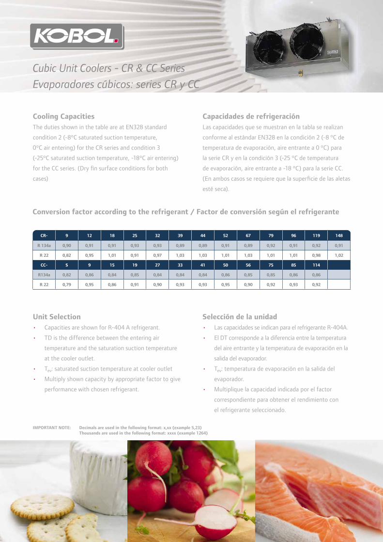
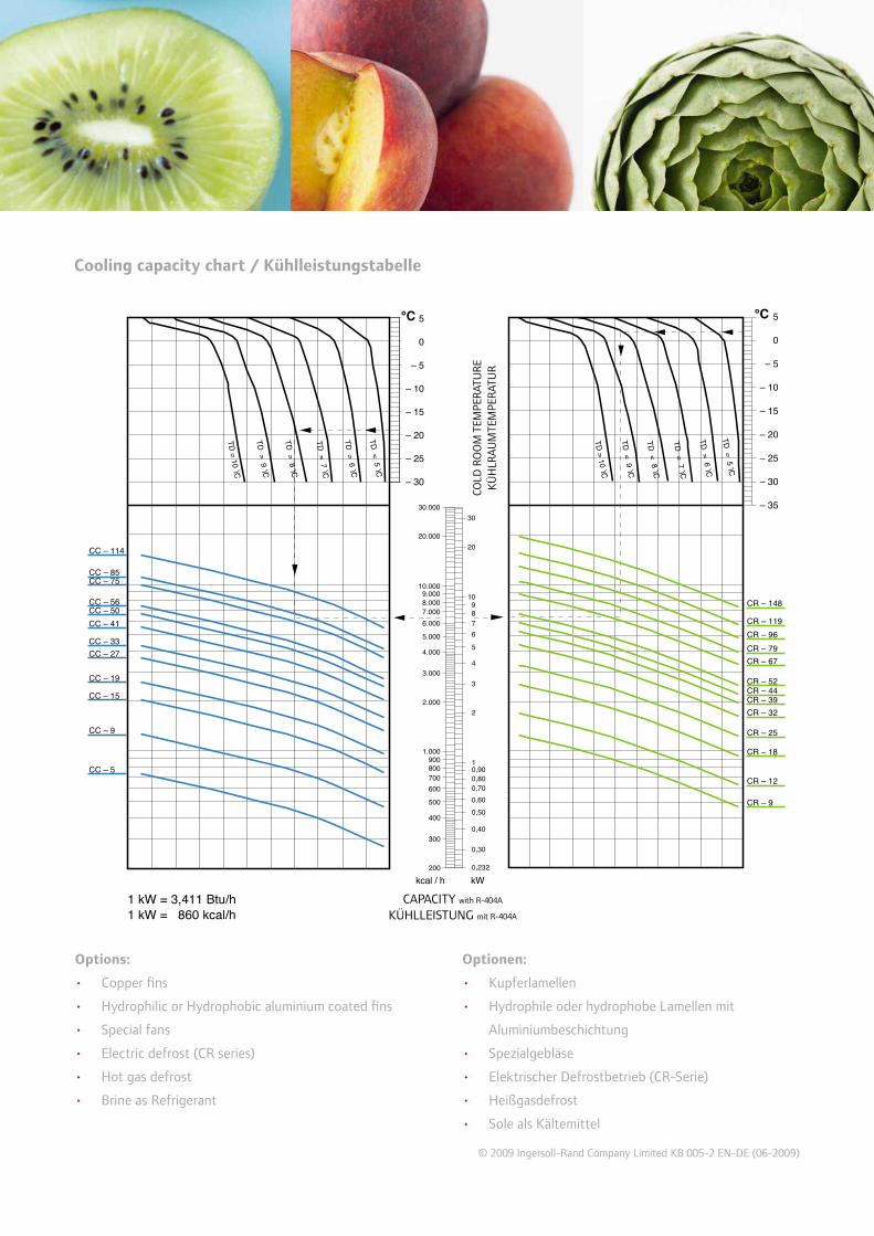
Cooling Capacities
The duties shown in the table are at EN328 standard
condition 2 (-8ºC saturated suction temperature,
0ºC air entering) for the CR series and condition 3
(-25ºC saturated suction temperature, -18ºC air entering)
for the CC series. (Dry fi n surface conditions for both
cases)
Unit Selection
Capacities are shown for R-404 A refrigerant.•
TD is the difference between the entering air •
temperature and the saturation suction temperature
at the cooler outlet.
T• ev: saturated suction temperature at cooler outlet
Multiply shown capacity by appropriate factor to give •
performance with chosen refrigerant.
CR- 9 12 18 25 32 39 44 52 67 79 96 119 148
R 134a 0,90 0,91 0,91 0,93 0,93 0,89 0,89 0,91 0,89 0,92 0,91 0,92 0,91
R 22 0,82 0,95 1,01 0,91 0,97 1,03 1,03 1,01 1,03 1,01 1,01 0,98 1,02
CC- S 9 15 19 27 33 41 50 56 75 85 114
R134a 0,82 0,86 0,84 0,85 0,84 0,84 0,84 0,86 0,85 0,85 0,86 0,86
R 22 0,79 0,95 0,86 0,91 0,90 0,93 0,93 0,95 0,90 0,92 0,93 0,92
Capacidades de refrigeración
Las capacidades que se muestran en la tabla se realizan
conforme al estándar EN328 en la condición 2 (-8 ºC de
temperatura de evaporación, aire entrante a 0 ºC) para
la serie CR y en la condición 3 (-25 ºC de temperatura
de evaporación, aire entrante a -18 ºC) para la serie CC.
(En ambos casos se requiere que la superfi cie de las aletas
esté seca).
Selección de la unidad
Las capacidades se indican para el refrigerante R-404A.•
El DT corresponde a la diferencia entre la temperatura •
del aire entrante y la temperatura de evaporación en la
salida del evaporador.
T• ev: temperatura de evaporación en la salida del
evaporador.
Multiplique la capacidad indicada por el factor •
correspondiente para obtener el rendimiento con
el refrigerante seleccionado.
Conversion factor according to the refrigerant / Factor de conversión según el refrigerante
IMPORTANT NOTE: Decimals are used in the following format: x,xx (example 5,23)
Thousands are used in the following format: xxxx (example 1264)

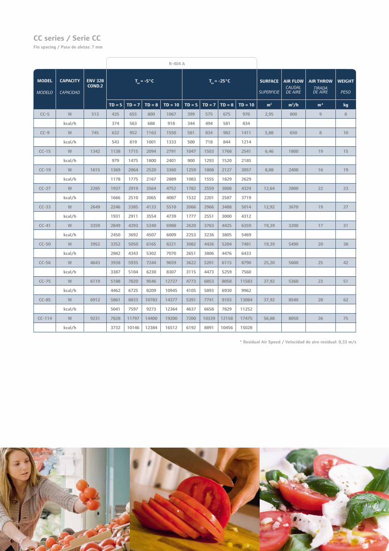
* Residual Air Speed / Velocidad de aire residual: 0,33 m/s
MODEL
MODELO
CAPACITY
CAPACIDAD
ENV 328
COND.2
Tev
= -5°C
SURFACE
SUPERFICIE
AIR FLOWCAUDAL DE AIRE
AIR THROW
TIRADA AIRE
WEIGHT
PESO
TD = 5 TD = 7 TD = 8 TD = 10 m2 m3/h m* kg
CR-9 W 949 707 1073 1311 1748 5,63 800 8 9
kcal/h 608 923 1127 1503
CR-12 W 1099 818 1242 1516 2023 8,45 650 7 11
kcal/h 704 1068 1304 1739
CR-18 W 1556 1158 1758 2147 2862 8,45 1600 9 14
kcal/h 996 1512 1846 2461
CR-25 W 2306 1718 2607 3183 4244 13,83 1500 14,5 18
kcal/h 1478 2242 2737 3650
CR-32 W 2810 2093 3174 3877 5169 16,89 2200 10 22
kcal/h 1800 2730 3334 4445
CR-39 W 3201 2385 3617 4417 5890 18,03 2825 20 24
kcal/h 2051 3111 3799 5065
CR-44 W 3616 2694 4086 4989 6653 18,43 3500 17 28
kcal/h 2317 3514 4291 5721
CR-52 W 4215 3140 4763 5817 7755 24,13 2870 16 36
kcal/h 2700 4096 5003 6669
CR-67 W 5484 4085 6197 7568 10090 27,65 5250 18 40
kcal/h 3513 5329 6508 8678
CR-79 W 6605 4921 7464 9115 12154 36,06 5650 24 45
kcal/h 4232 6419 7839 10452
CR-96 W 8044 5993 9090 11100 14801 54,09 5200 22 55
kcal/h 5154 7817 9546 12729
CR-119 W 10244 7631 11575 14136 18848 54,09 8475 27 65
kcal/h 6563 9955 12157 16209
CR-148 W 12234 9114 13824 16883 22511 81,07 7800 25 81
kcal/h 7838 11889 14519 19359
CR series / Serie CRFin spacing / Paso de aletas: 4,5 mm
R-404 A
MODEL
MODELO
CAPACITY
CAPACIDAD
ENV 328
COND.2T
ev = -5°C T
ev = -25°C SURFACE
SUPERFICIE
AIR FLOW
CAUDAL DE AIRE
AIR THROW
TIRADA DE AIRE
WEIGHT
PESO
TD = 5 TD = 7 TD = 8 TD = 10 TD = 5 TD = 7 TD = 8 TD = 10 m2 m3/h m* kg
CC-5 W 513 435 655 800 1067 399 575 675 970 2,95 800 9 8
kcal/h 374 563 688 918 344 494 581 834
CC-9 W 745 632 952 1163 1550 581 834 982 1411 5,88 650 8 10
kcal/h 543 819 1001 1333 500 718 844 1214
CC-15 W 1342 1138 1715 2094 2791 1047 1503 1768 2541 6,46 1800 19 15
kcal/h 979 1475 1800 2401 900 1293 1520 2185
CC-19 W 1615 1369 2064 2520 3360 1259 1808 2127 3057 8,88 2400 16 19
kcal/h 1178 1775 2167 2889 1083 1555 1829 2629
CC-27 W 2285 1937 2919 3564 4752 1782 2559 3008 4324 12,64 2800 22 23
kcal/h 1666 2510 3065 4087 1532 2201 2587 3719
CC-33 W 2649 2246 3385 4133 5510 2066 2966 3488 5014 12,92 3670 19 27
kcal/h 1931 2911 3554 4739 1777 2551 3000 4312
CC-41 W 3359 2849 4293 5240 6988 2620 3763 4425 6359 19,39 3200 17 31
kcal/h 2450 3692 4507 6009 2253 3236 3805 5469
CC-50 W 3952 3352 5050 6165 8221 3082 4426 5204 7481 19,39 5490 20 38
kcal/h 2882 4343 5302 7070 2651 3806 4476 6433
CC-56 W 4643 3938 5935 7244 9659 3622 5201 6115 8790 25,20 5600 25 42
kcal/h 3387 5104 6230 8307 3115 4473 5259 7560
CC-75 W 6119 5188 7820 9546 12727 4773 6853 8058 11583 37,92 5360 23 51
kcal/h 4462 6725 8209 10945 4105 5893 6930 9962
CC-85 W 6912 5861 8833 10783 14377 5391 7741 9103 13084 37,92 8540 28 62
kcal/h 5041 7597 9273 12364 4637 6658 7829 11252
CC-114 W 9231 7828 11797 14400 19200 7200 10339 12158 17475 56,88 8050 26 75
kcal/h 3732 10146 12384 16512 6192 8891 10456 15028
CC series / Serie CCFin spacing / Paso de aletas: 7 mm
R-404 A
* Residual Air Speed / Velocidad de aire residual: 0,33 m/s

DRAINAGE
DRENAJEØ
MODEL
MODELO
CR-9 CR-12 CR-18 CR-25 CR-32 CR-39 CR-44 CR-523/4”
CC-5 CC-9 CC-15 CC-19 CC-27 CC-33 CC-41
CR-67 CR-79 CR-96 CR-119 CR-1481 1/4”
CC-50 CC-56 CC-75 CC-85 CC-114
Drainage / Drenaje
* Three phase / Trifásicoø
o
utl
et
ø sa
lid
a
ø inlet
ø entrada
ø drainage
ø drenaje
MODEL
MODELO
FANS
VENTILADORES
POWER & CURRENT CONSUMPTION
CONSUMO ENERGÉTICO Y DE CORRIENTE
DIMENSIONS (mm)
DIMENSIONES (mm)
INLET
ENTRADA
OUTLET
SALIDA
ELECTRIC HEATERS
RESISTENCIAS
Num Ø (mm) W 230 V (Δ) 400 V A B C D E Ø Ø W TOT
A TOT
CR-9 CC-5 1 250 56 0,35 575 355 410 370 375 1/2” 1/2” 903 1,53
CR-12 CC-9 1 250 56 0,35 575 355 410 370 375 1/2” 1/2” 1083 1,86
CR-18 2 250 112 0,70 905 685 410 370 375 1/2” 1/2” 1532 2,64
CR-25 CC-15 1 315 110 0,50 695 475 450 410 440 1/2” 5/8” 1803 3,88
CR-32 CC-19 3 250 168 1,05 1235 1015 410 370 375 1/2” 5/8” 2145 3,75
CR-39 CC-27 1 350 145 0,58 0,33* 905 685 490 450 565 1/2” 5/8” 3017 5,28
CR-44 CC-33 2 315 220 1,00 1145 925 450 410 440 1/2” 5/8” 3162 6,90
CR-52 CC-41 2 315 220 1,00 1145 925 450 410 440 1/2” 7/8”-5/8” 3162 6,90
CR-67 CC-50 3 315 330 1,50 1595 1375 450 410 440 1/2” 7/8” 4521 9,92
CR-79 CC-56 2 350 290 1,16 0,66* 1565 1345 490 450 565 1/2” 7/8” 5525 9,72
CR-96 CC-75 2 350 290 1,16 0,66* 1565 1345 490 450 565 5/8” 1 1/8” 5525 9,72
CR-119 CC-85 3 350 435 1,74 0,99* 2225 2005 490 450 565 5/8* 1 1/8* 7982 14,16
CR-148 CC-114 3 350 435 1,74 0,99* 2225 1005 490 450 565 5/8” 1 3/8”-1 1/8” 7982 14,16
Technical Features / Características técnicas
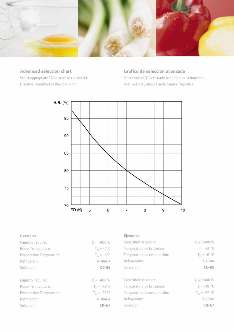
95
90
85
80
75
70
H.R. (%)
TD (K) 5 6 7 8 9 10
Examples:
Capacity required: Q = 7400 W
Room Temperature: Tcf = +2°C
Evaporation Temperature: Tev = -6°C
Refrigerant: R-404 A
Selection: CC-85
Capacity required: Q = 7400 W
Room Temperature: Tcf = -19°C
Evaporation Temperature: Tev = -27°C
Refrigerant: R-404 A
Selection: CR-67
Ejemplos:
Capacidad necesaria: Q = 7.400 W
Temperatura de la cámara: Tr = +2 °C
Temperatura de evaporación: Tev = -6 °C
Refrigerante: R-404A
Selección: CC-85
Capacidad necesaria: Q = 7.400 W
Temperatura de la cámara: Tr = -19 °C
Temperatura de evaporación: Tev = -27 °C
Refrigerante: R-404A
Selección: CR-67
Advanced selection chart
Select appropriate TD to achieve chosen R.H.
(Relative Humidity) in the cold room.
Gráfi co de selección avanzada
Seleccione el DT adecuado para obtener la humedad
relativa (H.R.) elegida en la cámara frigorífi ca.

TD = 10 ϒC
TD = 9 ϒC
TD = 8 ϒC
TD = 7 ϒC
TD = 6 ϒC
TD = 5 ϒC
COLD
RO
OM
TEM
PERA
TURE
TEM
PERA
TURA
DE
LA C
ÁM
ARA
FRI
GO
RÍFI
CA
5
0
– 5
– 10
– 15
– 20
– 25
– 30
°C
10.0009.0008.0007.0006.000
5.000
4.000
3.000
2.000
1.000900800700600
500
400
300
200
20.000
30.00030
20
109876
5
4
3
2
10,900,800,700,600,50
0,40
0,30
0,232
CAPACITY with R-404A
CAPACIDAD con R-404A
1 kW = 3,411 Btu/h1 kW = 860 kcal/h
kcal / h kW
CC – 114
CC – 85CC – 75
CC – 56CC – 50CC – 41
CC – 33CC – 27
CC – 19
CC – 15
CC – 9
CC – 5
TD = 10 ϒC
TD = 9 ϒC
TD = 8 ϒC
TD = 7 ϒC
TD = 6 ϒC
TD = 5 ϒC
5
0
– 5
– 10
– 15
– 20
– 25
– 30
– 35
°C
CR – 148
CR – 119CR – 96CR – 79CR – 67
CR – 52CR – 44CR – 39CR – 32
CR – 25
CR – 18
CR – 12
CR – 9
© 2009 Ingersoll-Rand Company Limited KB 005-2 EN-ES (06-2009)
Cooling capacity chart / Gráfi co de capacidad de refrigeración
Options:
Copper fi ns•
Hydrophilic or Hydrophobic aluminium coated fi ns•
Special fans•
Electric defrost (CR series)•
Hot gas defrost•
Brine as Refrigerant•
Opciones:
Aletas de cobre•
Aletas de aluminio hidrófi lo o hidrófobo lacadas•
Ventiladores especiales•
Desescarche eléctrico (serie CR)•
Desescarche por gas caliente•
Agua glicolada como refrigerante•

Cubic Unit Coolers - CR & CC Series
Cooling Capacities
The duties shown in the table are at EN328 standard
condition 2 (-8ºC saturated suction temperature,
0ºC air entering) for the CR series and condition 3
(-25ºC saturated suction temperature, -18ºC air entering)
for the CC series. (Dry fi n surface conditions for both
cases)
Unit Selection
Capacities are shown for R-404 A refrigerant.•
TD is the difference between the entering air •
temperature and the saturation suction temperature
at the cooler outlet.
T• ev: saturated suction temperature at cooler outlet
Multiply shown capacity by appropriate factor to give •
performance with chosen refrigerant.
CR- 9 12 18 25 32 39 44 52 67 79 96 119 148
R 134a 0,90 0,91 0,91 0,93 0,93 0,89 0,89 0,91 0,89 0,92 0,91 0,92 0,91
R 22 0,82 0,95 1,01 0,91 0,97 1,03 1,03 1,01 1,03 1,01 1,01 0,98 1,02
CC- S 9 15 19 27 33 41 50 56 75 85 114
R134a 0,82 0,86 0,84 0,85 0,84 0,84 0,84 0,86 0,85 0,85 0,86 0,86
R 22 0,79 0,95 0,86 0,91 0,90 0,93 0,93 0,95 0,90 0,92 0,93 0,92
Conversion factor according to the refrigerant /
IMPORTANT NOTE: Decimals are used in the following format: x,xx (example 5,23)
Thousands are used in the following format: xxxx (example 1264)
Freistehende Gerätekühler – CR- und CC-Serien
Kühlleistungen
Der in der Tabelle gezeigte Betrieb fi ndet für die CR-Serie
bei der EN328-Standardbedingung 2 (-8 °C gesättigte
Temperatur, 0 °C Einlasstemperatur) und für die CC-Serie
bei Bedingung 3 (-25 °C gesättigte Temperatur, -18 °C
Einlasstemperatur) statt (trockene Kühlrippen für beide
Temperaturen).
Umrechnungsfaktor des jeweiligen Kühlmittels
Geräteauswahl
Die dargestellten Leistungen werden mit dem •
Kältemittel R-404A erzielt.
TD ist der Unterschied zwischen der Temperatur der •
eingelassenen Luft und der Sättigungstemperatur am
Luftauslass des Gerätekühlers.
T• ev: gesättigte Temperatur am Luftauslass des
Gerätekühlers.
Multiplizieren Sie die angegebene Leistung mit den •
zutreffenden Faktoren, um die tatsächliche Leistung
mit dem gewählten Kühlmittel zu bestimmen.

* Residual Air Speed /
MODEL CAPACITY ENV 328
COND.2
Tev
= -5°C
SURFACE AIR FLOW AIR THROW WEIGHT
TD = 5 TD = 7 TD = 8 TD = 10 m2 m3/h m* kg
CR-9 W 949 707 1073 1311 1748 5,63 800 8 9
kcal/h 608 923 1127 1503
CR-12 W 1099 818 1242 1516 2023 8,45 650 7 11
kcal/h 704 1068 1304 1739
CR-18 W 1556 1158 1758 2147 2862 8,45 1600 9 14
kcal/h 996 1512 1846 2461
CR-25 W 2306 1718 2607 3183 4244 13,83 1500 14,5 18
kcal/h 1478 2242 2737 3650
CR-32 W 2810 2093 3174 3877 5169 16,89 2200 10 22
kcal/h 1800 2730 3334 4445
CR-39 W 3201 2385 3617 4417 5890 18,03 2825 20 24
kcal/h 2051 3111 3799 5065
CR-44 W 3616 2694 4086 4989 6653 18,43 3500 17 28
kcal/h 2317 3514 4291 5721
CR-52 W 4215 3140 4763 5817 7755 24,13 2870 16 36
kcal/h 2700 4096 5003 6669
CR-67 W 5484 4085 6197 7568 10090 27,65 5250 18 40
kcal/h 3513 5329 6508 8678
CR-79 W 6605 4921 7464 9115 12154 36,06 5650 24 45
kcal/h 4232 6419 7839 10452
CR-96 W 8044 5993 9090 11100 14801 54,09 5200 22 55
kcal/h 5154 7817 9546 12729
CR-119 W 10244 7631 11575 14136 18848 54,09 8475 27 65
kcal/h 6563 9955 12157 16209
CR-148 W 12234 9114 13824 16883 22511 81,07 7800 25 81
kcal/h 7838 11889 14519 19359
CR series /Fin spacing /
R-404 A
MODELL KÄLTELEISTUNGFLÄCHE LUFTZIRKULATION LUFTDURCHSATZ GEWICHT
CR-SerieLamellenabstand: 4,5 mm
Geschwindigkeit der Restluft: 0,33 m/s

MODEL CAPACITY ENV 328
COND.2T
ev = -5°C T
ev = -25°C SURFACE AIR FLOW AIR THROW WEIGHT
TD = 5 TD = 7 TD = 8 TD = 10 TD = 5 TD = 7 TD = 8 TD = 10 m2 m3/h m* kg
CC-5 W 513 435 655 800 1067 399 575 675 970 2,95 800 9 8
kcal/h 374 563 688 918 344 494 581 834
CC-9 W 745 632 952 1163 1550 581 834 982 1411 5,88 650 8 10
kcal/h 543 819 1001 1333 500 718 844 1214
CC-15 W 1342 1138 1715 2094 2791 1047 1503 1768 2541 6,46 1800 19 15
kcal/h 979 1475 1800 2401 900 1293 1520 2185
CC-19 W 1615 1369 2064 2520 3360 1259 1808 2127 3057 8,88 2400 16 19
kcal/h 1178 1775 2167 2889 1083 1555 1829 2629
CC-27 W 2285 1937 2919 3564 4752 1782 2559 3008 4324 12,64 2800 22 23
kcal/h 1666 2510 3065 4087 1532 2201 2587 3719
CC-33 W 2649 2246 3385 4133 5510 2066 2966 3488 5014 12,92 3670 19 27
kcal/h 1931 2911 3554 4739 1777 2551 3000 4312
CC-41 W 3359 2849 4293 5240 6988 2620 3763 4425 6359 19,39 3200 17 31
kcal/h 2450 3692 4507 6009 2253 3236 3805 5469
CC-50 W 3952 3352 5050 6165 8221 3082 4426 5204 7481 19,39 5490 20 38
kcal/h 2882 4343 5302 7070 2651 3806 4476 6433
CC-56 W 4643 3938 5935 7244 9659 3622 5201 6115 8790 25,20 5600 25 42
kcal/h 3387 5104 6230 8307 3115 4473 5259 7560
CC-75 W 6119 5188 7820 9546 12727 4773 6853 8058 11583 37,92 5360 23 51
kcal/h 4462 6725 8209 10945 4105 5893 6930 9962
CC-85 W 6912 5861 8833 10783 14377 5391 7741 9103 13084 37,92 8540 28 62
kcal/h 5041 7597 9273 12364 4637 6658 7829 11252
CC-114 W 9231 7828 11797 14400 19200 7200 10339 12158 17475 56,88 8050 26 75
kcal/h 3732 10146 12384 16512 6192 8891 10456 15028
CC series /Fin spacing /
R-404 A
* Residual Air Speed /
CC-SerieLamellenabstand: 7 mm
MODELL KÄLTELEISTUNG FLÄCHE LUFT-ZIRKULATION
LUFT-DURCHSATZ
GEWICHT
Geschwindigkeit der Restluft: 0,33 m/s

DRAINAGE
Ø
MODEL
CR-9 CR-12 CR-18 CR-25 CR-32 CR-39 CR-44 CR-523/4”
CC-5 CC-9 CC-15 CC-19 CC-27 CC-33 CC-41
CR-67 CR-79 CR-96 CR-119 CR-1481 1/4”
CC-50 CC-56 CC-75 CC-85 CC-114
Drainage /
* Three phase /ø
o
utl
et
ø inlet
ø drainage
MODEL FANS
POWER & CURRENT CONSUMPTION
DIMENSIONS (mm)
INLET
OUTLET
ELECTRIC HEATERS
Num Ø (mm) W 230 V (Δ) 400 V A B C D E Ø Ø W TOT
A TOT
CR-9 CC-5 1 250 56 0,35 575 355 410 370 375 1/2” 1/2” 903 1,53
CR-12 CC-9 1 250 56 0,35 575 355 410 370 375 1/2” 1/2” 1083 1,86
CR-18 2 250 112 0,70 905 685 410 370 375 1/2” 1/2” 1532 2,64
CR-25 CC-15 1 315 110 0,50 695 475 450 410 440 1/2” 5/8” 1803 3,88
CR-32 CC-19 3 250 168 1,05 1235 1015 410 370 375 1/2” 5/8” 2145 3,75
CR-39 CC-27 1 350 145 0,58 0,33* 905 685 490 450 565 1/2” 5/8” 3017 5,28
CR-44 CC-33 2 315 220 1,00 1145 925 450 410 440 1/2” 5/8” 3162 6,90
CR-52 CC-41 2 315 220 1,00 1145 925 450 410 440 1/2” 7/8”-5/8” 3162 6,90
CR-67 CC-50 3 315 330 1,50 1595 1375 450 410 440 1/2” 7/8” 4521 9,92
CR-79 CC-56 2 350 290 1,16 0,66* 1565 1345 490 450 565 1/2” 7/8” 5525 9,72
CR-96 CC-75 2 350 290 1,16 0,66* 1565 1345 490 450 565 5/8” 1 1/8” 5525 9,72
CR-119 CC-85 3 350 435 1,74 0,99* 2225 2005 490 450 565 5/8* 1 1/8* 7982 14,16
CR-148 CC-114 3 350 435 1,74 0,99* 2225 1005 490 450 565 5/8” 1 3/8”-1 1/8” 7982 14,16
Technical Features / Technische Daten
MODELL VENTILATOREN LEISTUNGSAUFNAHME UND STROMVERBRAUCH
ABMESSUNGEN (MM) EINLASS AUSLASS ELEKTROHEIZUNGEN
Drehstrom
Ablauf
MODELL
ABLAUF
ø A
usl
ass
ø Einlass
ø Ablauf

95
90
85
80
75
70
H.R. (%)
TD (K) 5 6 7 8 9 10
Examples:
Capacity required: Q = 7400 W
Room Temperature: Tcf = +2°C
Evaporation Temperature: Tev = -6°C
Refrigerant: R-404 A
Selection: CC-85
Capacity required: Q = 7400 W
Room Temperature: Tcf = -19°C
Evaporation Temperature: Tev = -27°C
Refrigerant: R-404 A
Selection: CR-67
Advanced selection chart
Select appropriate TD to achieve chosen R.H.
(Relative Humidity) in the cold room.
Erweiterte Auswahltabelle
Wählen Sie den entsprechenden Temperaturunterschied (TD),
um im Kühlraum die gewünschte relative Feuchtigkeit (R.H.)
zu erreichen.
Beispiele:
Erforderliche Leistung: Q = 7.400 W
Raumtemperatur: Tcf = +2 °C
Verdampfungstemperatur: Tev = -6 °C
Kältemittel: R-404A
Auswahl: CC-85
Erforderliche Leistung: Q = 7.400 W
Raumtemperatur: Tcf = -19 °C
Verdampfungstemperatur: Tev = -27 °C
Kältemittel: R-404A
Auswahl: CR-67
R.H. (%)
TD = 10 ϒC
TD = 9 ϒC
TD = 8 ϒC
TD = 7 ϒC
TD = 6 ϒC
TD = 5 ϒC
5
0
– 5
– 10
– 15
– 20
– 25
– 30
°C
10.0009.0008.0007.0006.000
5.000
4.000
3.000
2.000
1.000900800700600
500
400
300
200
20.000
30.00030
20
109876
5
4
3
2
10,900,800,700,600,50
0,40
0,30
0,232
1 kW = 3,411 Btu/h1 kW = 860 kcal/h
kcal / h kW
CC – 114
CC – 85CC – 75
CC – 56CC – 50CC – 41
CC – 33CC – 27
CC – 19
CC – 15
CC – 9
CC – 5
TD = 10 ϒC
TD = 9 ϒC
TD = 8 ϒC
TD = 7 ϒC
TD = 6 ϒC
TD = 5 ϒC
5
0
– 5
– 10
– 15
– 20
– 25
– 30
– 35
°C
CR – 148
CR – 119CR – 96CR – 79CR – 67
CR – 52CR – 44CR – 39CR – 32
CR – 25
CR – 18
CR – 12
CR – 9
CAPACITY with R-404A
CAPACITE avec R-404A
COLD
RO
OM
TEM
PERA
TURE
TEM
PERA
TURE
DE
LA C
HA
MBR
E FR
OID
E
© 2009 Ingersoll-Rand Company Limited KB 005-2 EN-DE (06-2009)
Cooling capacity chart /
Options:
Copper fi ns•
Hydrophilic or Hydrophobic aluminium coated fi ns•
Special fans•
Electric defrost (CR series)•
Hot gas defrost•
Brine as Refrigerant•
Optionen:
Kupferlamellen•
Hydrophile oder hydrophobe Lamellen mit •
Aluminiumbeschichtung
Spezialgebläse•
Elektrischer Defrostbetrieb (CR-Serie)•
Heißgasdefrost•
Sole als Kältemittel•
Kühlleistungstabelle
CAPACITY with R-404A
KÜHLLEISTUNG mit R-404A
CO
LD
RO
OM
TE
MP
ER
AT
UR
E
KÜ
HLR
AU
MT
EM
PE
RA
TU
R

Cubic Unit Coolers - CR & CC Series
Évaporateurs cubiques industriels - Séries CR et CC
Cooling Capacities
The duties shown in the table are at EN328 standard
condition 2 (-8ºC saturated suction temperature,
0ºC air entering) for the CR series and condition 3
(-25ºC saturated suction temperature, -18ºC air entering)
for the CC series. (Dry fi n surface conditions for both
cases)
Unit Selection
Capacities are shown for R-404 A refrigerant.•
TD is the difference between the entering air •
temperature and the saturation suction temperature
at the cooler outlet.
T• ev: saturated suction temperature at cooler outlet
Multiply shown capacity by appropriate factor to give •
performance with chosen refrigerant.
CR- 9 12 18 25 32 39 44 52 67 79 96 119 148
R 134a 0,90 0,91 0,91 0,927 0,93 0,89 0,89 0,91 0,89 0,92 0,91 0,92 0,91
R 22 0,82 0,95 1,01 0,91 0,97 1,03 1,03 1,01 1,03 1,01 1,01 0,98 1,02
CC- S 9 15 19 27 33 41 50 56 75 85 114
R134a 0,82 0,86 0,84 0,85 0,84 0,84 0,84 0,86 0,85 0,85 0,86 0,86
R 22 0,79 0,95 0,86 0,91 0,90 0,93 0,93 0,95 0,90 0,92 0,93 0,92
Puissance frigorifi que du système
Les puissances indiquées dans le tableau sont conformes
à la norme EN328, condition 2 (température d’aspiration
saturée -8 ºC, entrée d’air 0 ºC) pour la série CR et
à la norme EN328, condition 3 (température d’aspiration
saturée -25 ºC, entrée d’air -18 ºC) pour la série CC.
(La surface des ailettes doit être sèche dans les deux cas.)
Sélection des modèles :
Les puissances sont indiquées pour le réfrigérant •
R-404 A.
TD correspond à la différence entre la température •
de l’air entrant et la température d’aspiration saturée
en sortie du groupe frigorifi que.
T• ev correspond à la température d’aspiration saturée
en sortie du groupe frigorifi que.
Multipliez la puissance indiquée par le facteur •
approprié pour obtenir les performances avec
le réfrigérant choisi.
Conversion factor according to the refrigerant / Facteur de conversion d’après le refrigérant
IMPORTANT NOTE: Decimals are used in the following format: x,xx (example 5,23)
Thousands are used in the following format: xxxx (example 1264)

* Residual Air Speed / Vitesse d’air résiduelle : 0,33 m/s
MODEL
MODÈLE
CAPACITY
CAPACITÉ
ENV 328
COND.2T
ev = -5°C SURFACE
SURFACE
AIR FLOW
DÉBIT D’AIR
AIR THROW
PROJECTION D’AIR
WEIGHT
POIDS
TD = 5 TD = 7 TD = 8 TD = 10 m2 m3/h m* kg
CR-9 W 949 707 1073 1311 1748 5,63 800 8 9
kcal/h 608 923 1127 1503
CR-12 W 1099 818 1242 1516 2023 8,45 650 7 11
kcal/h 704 1068 1304 1739
CR-18 W 1556 1158 1758 2147 2862 8,45 1600 9 14
kcal/h 996 1512 1846 2461
CR-25 W 2306 1718 2607 3183 4244 13,83 1500 14,5 18
kcal/h 1478 2242 2737 3650
CR-32 W 2810 2093 3174 3877 5169 16,89 2200 10 22
kcal/h 1800 2730 3334 4445
CR-39 W 3201 2385 3617 4417 5890 18,03 2825 20 24
kcal/h 2051 3111 3799 5065
CR-44 W 3616 2694 4086 4989 6653 18,43 3500 17 28
kcal/h 2317 3514 4291 5721
CR-52 W 4215 3140 4763 5817 7755 24,13 2870 16 36
kcal/h 2700 4096 5003 6669
CR-67 W 5484 4085 6197 7568 10090 27,65 5250 18 40
kcal/h 3513 5329 6508 8678
CR-79 W 6605 4921 7464 9115 12154 36,06 5650 24 45
kcal/h 4232 6419 7839 10452
CR-96 W 8044 5993 9090 11100 14801 54,09 5200 22 55
kcal/h 5154 7817 9546 12729
CR-119 W 10244 7631 11575 14136 18848 54,09 8475 27 65
kcal/h 6563 9955 12157 16209
CR-148 W 12234 9114 13824 16883 22511 81,07 7800 25 81
kcal/h 7838 11889 14519 19359
CR series / Série CRFin spacing / Pas d’ailettes : 4,5 mm
R-404 A

MODEL
MODÈLE
CAPACITY
CAPACITÉ
ENV 328
COND.2T
ev = -5°C T
ev = -25°C SURFACE
SURFACE
AIR FLOW
DÉBIT D’AIR
AIR THROW
PROJECTION D’AIR
WEIGHT
POIDS
TD = 5 TD = 7 TD = 8 TD = 10 TD = 5 TD = 7 TD = 8 TD = 10 m2 m3/h m* kg
CC-5 W 513 435 655 800 1067 399 575 675 970 2,95 800 9 8
kcal/h 374 563 688 918 344 494 581 834
CC-9 W 745 632 952 1163 1550 581 834 982 1411 5,88 650 8 10
kcal/h 543 819 1001 1333 500 718 844 1214
CC-15 W 1342 1138 1715 2094 2791 1047 1503 1768 2541 6,46 1800 19 15
kcal/h 979 1475 1800 2401 900 1293 1520 2185
CC-19 W 1615 1369 2064 2520 3360 1259 1808 2127 3057 8,88 2400 16 19
kcal/h 1178 1775 2167 2889 1083 1555 1829 2629
CC-27 W 2285 1937 2919 3564 4752 1782 2559 3008 4324 12,64 2800 22 23
kcal/h 1666 2510 3065 4087 1532 2201 2587 3719
CC-33 W 2649 2246 3385 4133 5510 2066 2966 3488 5014 12,92 3670 19 27
kcal/h 1931 2911 3554 4739 1777 2551 3000 4312
CC-41 W 3359 2849 4293 5240 6988 2620 3763 4425 6359 19,39 3200 17 31
kcal/h 2450 3692 4507 6009 2253 3236 3805 5469
CC-50 W 3952 3352 5050 6165 8221 3082 4426 5204 7481 19,39 5490 20 38
kcal/h 2882 4343 5302 7070 2651 3806 4476 6433
CC-56 W 4643 3938 5935 7244 9659 3622 5201 6115 8790 25,20 5600 25 42
kcal/h 3387 5104 6230 8307 3115 4473 5259 7560
CC-75 W 6119 5188 7820 9546 12727 4773 6853 8058 11583 37,92 5360 23 51
kcal/h 4462 6725 8209 10945 4105 5893 6930 9962
CC-85 W 6912 5861 8833 10783 14377 5391 7741 9103 13084 37,92 8540 28 62
kcal/h 5041 7597 9273 12364 4637 6658 7829 11252
CC-114 W 9231 7828 11797 14400 19200 7200 10339 12158 17475 56,88 8050 26 75
kcal/h 3732 10146 12384 16512 6192 8891 10456 15028
CC series / Série CCFin spacing / Pas d’ailettes : 7 mm
R-404 A
* Residual air speed / Vitesse d’air résiduelle : 0,33 m/s

DRAINAGE
VIDANGEØ
MODEL
MODÈLE
CR-9 CR-12 CR-18 CR-25 CR-32 CR-39 CR-44 CR-523/4”
CC-5 CC-9 CC-15 CC-19 CC-27 CC-33 CC-41
CR-67 CR-79 CR-96 CR-119 CR-1481 1/4”
CC-50 CC-56 CC-75 CC-85 CC-114
Drainage / Vidange
* Three phase / Triphaséø
ou
tlet
ø s
ort
ie
ø inlet
ø entrée
ø drainage
ø vidange
MODEL
MODÈLE
FANS
VENTILATEURS
POWER & CURRENT CONSUMPTION
CONSOMMATION ÉLECTRIQUE
DIMENSIONS (mm)
DIMENSIONS (mm)
INLET
ENTRÉE
OUTLET
SORTIE
ELECTRIC HEATERS
RÉSISTANCES ÉLECTRIQUES
Num Ø (mm) W 230 V (Δ) 400 V A B C D E Ø Ø W TOT
A TOT
CR-9 CC-5 1 250 56 0,35 575 355 410 370 375 1/2” 1/2” 903 1,53
CR-12 CC-9 1 250 56 0,35 575 355 410 370 375 1/2” 1/2” 1083 1,86
CR-18 2 250 112 0,70 905 685 410 370 375 1/2” 1/2” 1532 2,64
CR-25 CC-15 1 315 110 0,50 695 475 450 410 440 1/2” 5/8” 1803 3,88
CR-32 CC-19 3 250 168 1,05 1235 1015 410 370 375 1/2” 5/8” 2145 3,75
CR-39 CC-27 1 350 145 0,58 0,33* 905 685 490 450 565 1/2” 5/8” 3017 5,28
CR-44 CC-33 2 315 220 1,00 1145 925 450 410 440 1/2” 5/8” 3162 6,90
CR-52 CC-41 2 315 220 1,00 1145 925 450 410 440 1/2” 7/8”-5/8” 3162 6,90
CR-67 CC-50 3 315 330 1,50 1595 1375 450 410 440 1/2” 7/8” 4521 9,92
CR-79 CC-56 2 350 290 1,16 0,66* 1565 1345 490 450 565 1/2” 7/8” 5525 9,72
CR-96 CC-75 2 350 290 1,16 0,66* 1565 1345 490 450 565 5/8” 1 1/8” 5525 9,72
CR-119 CC-85 3 350 435 1,74 0,99* 2225 2005 490 450 565 5/8* 1 1/8* 7982 14,16
CR-148 CC-114 3 350 435 1,74 0,99* 2225 1005 490 450 565 5/8” 1 3/8”-1 1/8” 7982 14,16
Technical Features / Caractéristiques techniques

95
90
85
80
75
70
H.R. (%)
TD (K) 5 6 7 8 9 10
Examples:
Capacity required: Q = 7400 W
Room Temperature: Tcf = +2°C
Evaporation Temperature: Tev = -6°C
Refrigerant: R-404 A
Selection: CC-85
Capacity required: Q = 7400 W
Room Temperature: Tcf = -19°C
Evaporation Temperature: Tev = -27°C
Refrigerant: R-404 A
Selection: CR-67
Exemples :
Puissance requise : Q = 7 400 W
Température ambiante : Tcf = +2 °C
Température d’évaporation : Tev = -6 °C
Réfrigérant : R-404 A
Sélection : CC-85
Puissance requise : Q = 7 400 W
Température ambiante : Tcf = +-19 °C
Température d’évaporation : Tev = -27 °C
Réfrigérant : R-404 A
Sélection : CR-67
Advanced selection chart
Select appropriate TD to achieve chosen R.H.
(Relative Humidity) in the cold room.
Graphique de sélection
Sélectionnez la différence TD appropriée pour
atteindre le taux d’humidité relative (HR) choisi dans
la chambre froide.

TD = 10 ϒC
TD = 9 ϒC
TD = 8 ϒC
TD = 7 ϒC
TD = 6 ϒC
TD = 5 ϒC
5
0
– 5
– 10
– 15
– 20
– 25
– 30
°C
10.0009.0008.0007.0006.000
5.000
4.000
3.000
2.000
1.000900800700600
500
400
300
200
20.000
30.00030
20
109876
5
4
3
2
10,900,800,700,600,50
0,40
0,30
0,232
1 kW = 3,411 Btu/h1 kW = 860 kcal/h
kcal / h kW
CC – 114
CC – 85CC – 75
CC – 56CC – 50CC – 41
CC – 33CC – 27
CC – 19
CC – 15
CC – 9
CC – 5
TD = 10 ϒC
TD = 9 ϒC
TD = 8 ϒC
TD = 7 ϒC
TD = 6 ϒC
TD = 5 ϒC
5
0
– 5
– 10
– 15
– 20
– 25
– 30
– 35
°C
CR – 148
CR – 119CR – 96CR – 79CR – 67
CR – 52CR – 44CR – 39CR – 32
CR – 25
CR – 18
CR – 12
CR – 9
CAPACITY with R-404A
CAPACITE avec R-404A
COLD
RO
OM
TEM
PERA
TURE
TEM
PERA
TURE
DE
LA C
HA
MBR
E FR
OID
E
Cooling capacity chart / Graphique de puissance frigorifi que
Options:
Copper fi ns•
Hydrophilic or Hydrophobic aluminium coated fi ns•
Special fans•
Electric defrost (CR series)•
Hot gas defrost•
Brine as Refrigerant•
Options :
Ailettes en cuivre•
Ailettes en aluminium traité hydrophilique ou •
hydrophobique
Ventilateurs spéciaux•
Dégivrage électrique (série CR) •
Dégivrage par gaz chauds•
Application pour saumure•
© 2009 Ingersoll-Rand Company Limited KB 005-2 EN-FR (06-2009)

Cubic Unit Coolers - CR & CC Series
Chłodnice kubiczne - serie CR i CC
Cooling Capacities
The duties shown in the table are at EN328 standard
condition 2 (-8ºC saturated suction temperature,
0ºC air entering) for the CR series and condition 3
(-25ºC saturated suction temperature, -18ºC air entering)
for the CC series. (Dry fi n surface conditions for both
cases)
Unit Selection
Capacities are shown for R-404 A refrigerant.•
TD is the difference between the entering air •
temperature and the saturation suction temperature
at the cooler outlet.
T• ev: saturated suction temperature at cooler outlet
Multiply shown capacity by appropriate factor to give •
performance with chosen refrigerant.
CR- 9 12 18 25 32 39 44 52 67 79 96 119 148
R 134a 0,90 0,91 0,91 0,93 0,93 0,89 0,89 0,91 0,89 0,92 0,91 0,92 0,91
R 22 0,82 0,95 1,01 0,91 0,97 1,03 1,03 1,01 1,03 1,01 1,01 0,98 1,02
CC- S 9 15 19 27 33 41 50 56 75 85 114
R134a 0,82 0,86 0,84 0,85 0,84 0,84 0,84 0,86 0,85 0,85 0,86 0,86
R 22 0,79 0,95 0,86 0,91 0,90 0,93 0,93 0,95 0,90 0,92 0,93 0,92
Wydajność chłodnicza
Podane w tabeli wartości wydajności nominalnej są
zgodne z warunkiem nr 2 normy EN328 (temperatura
nasyconego czynnika chłodniczego w przewodzie
ssawnym: -8ºC, temperatura powietrza wlotowego: 0ºC)
w przypadku urządzeń serii CR oraz z warunkiem
nr 3 (temperatura nasyconego czynnika chłodniczego
w przewodzie ssawnym: -25ºC, temperatura powietrza
wlotowego: -18ºC) w przypadku urządzeń serii CC.
(W obu przypadkach zakładany jest warunek suchej
powierzchni lameli).
Wybór agregatu
Podane wartości wydajności chłodniczej dotyczą •
czynnika chłodniczego R-404A.
TD jest różnicą temperatury powietrza wlotowego •
i temperatury nasycenia czynnika chłodniczego
w przewodzie ssawnym na wylocie z chłodnicy.
T• ev: temperatura nasyconego czynnika chłodniczego
w przewodzie ssawnym na wylocie z chłodnicy.
Aby uzyskać wydajność dla wybranego czynnika •
chłodniczego, należy pomnożyć podaną wydajność
przez odpowiedni współczynnik.
Conversion factor according to the refrigerant / Współczynnik konwersji w zależności od czynnika chłodniczego
IMPORTANT NOTE: Decimals are used in the following format: x,xx (example 5,23)
Thousands are used in the following format: xxxx (example 1264)

* Residual Air Speed / Prędkość powietrza w punkcie pomiaru: 0,33 m/s
MODEL
MODEL
CAPACITY
WYDAJNOŚĆ
ENV 328
COND.2T
ev = -5°C SURFACE
POWIERZCHNIA
AIR FLOWPRZEPŁYW POWIETRZA
AIR THROW
ZASIĘG STRUMIENIA POWIETRZA
WEIGHT
MASA
TD = 5 TD = 7 TD = 8 TD = 10 m2 m3/h m* kg
CR-9 W 949 707 1073 1311 1748 5,63 800 8 9
kcal/h 608 923 1127 1503
CR-12 W 1099 818 1242 1516 2023 8,45 650 7 11
kcal/h 704 1068 1304 1739
CR-18 W 1556 1158 1758 2147 2862 8,45 1600 9 14
kcal/h 996 1512 1846 2461
CR-25 W 2306 1718 2607 3183 4244 13,83 1500 14,5 18
kcal/h 1478 2242 2737 3650
CR-32 W 2810 2093 3174 3877 5169 16,89 2200 10 22
kcal/h 1800 2730 3334 4445
CR-39 W 3201 2385 3617 4417 5890 18,03 2825 20 24
kcal/h 2051 3111 3799 5065
CR-44 W 3616 2694 4086 4989 6653 18,43 3500 17 28
kcal/h 2317 3514 4291 5721
CR-52 W 4215 3140 4763 5817 7755 24,13 2870 16 36
kcal/h 2700 4096 5003 6669
CR-67 W 5484 4085 6197 7568 10090 27,65 5250 18 40
kcal/h 3513 5329 6508 8678
CR-79 W 6605 4921 7464 9115 12154 36,06 5650 24 45
kcal/h 4232 6419 7839 10452
CR-96 W 8044 5993 9090 11100 14801 54,09 5200 22 55
kcal/h 5154 7817 9546 12729
CR-119 W 10244 7631 11575 14136 18848 54,09 8475 27 65
kcal/h 6563 9955 12157 16209
CR-148 W 12234 9114 13824 16883 22511 81,07 7800 25 81
kcal/h 7838 11889 14519 19359
CR series / Seria CRFin spacing / Odstęp między lamelami: 4,5 mm
R-404 A

CC series / Série CCFin spacing / Odstęp między lamelami: 7 mm
MODEL
MODEL
CAPACITY
WYDAJNOŚĆ
ENV 328
COND.2T
ev = -5°C T
ev = -25°C SURFACE
POWIERZCHNIA
AIR FLOW
PRZEPŁYW POWIETRZA
AIR THROW
ZASIĘG STRUMIENIA POWIETRZA
WEIGHT
MASA
TD = 5 TD = 7 TD = 8 TD = 10 TD = 5 TD = 7 TD = 8 TD = 10 m2 m3/h m* kg
CC-5 W 513 435 655 800 1067 399 575 675 970 2,95 800 9 8
kcal/h 374 563 688 918 344 494 581 834
CC-9 W 745 632 952 1163 1550 581 834 982 1411 5,88 650 8 10
kcal/h 543 819 1001 1333 500 718 844 1214
CC-15 W 1342 1138 1715 2094 2791 1047 1503 1768 2541 6,46 1800 19 15
kcal/h 979 1475 1800 2401 900 1293 1520 2185
CC-19 W 1615 1369 2064 2520 3360 1259 1808 2127 3057 8,88 2400 16 19
kcal/h 1178 1775 2167 2889 1083 1555 1829 2629
CC-27 W 2285 1937 2919 3564 4752 1782 2559 3008 4324 12,64 2800 22 23
kcal/h 1666 2510 3065 4087 1532 2201 2587 3719
CC-33 W 2649 2246 3385 4133 5510 2066 2966 3488 5014 12,92 3670 19 27
kcal/h 1931 2911 3554 4739 1777 2551 3000 4312
CC-41 W 3359 2849 4293 5240 6988 2620 3763 4425 6359 19,39 3200 17 31
kcal/h 2450 3692 4507 6009 2253 3236 3805 5469
CC-50 W 3952 3352 5050 6165 8221 3082 4426 5204 7481 19,39 5490 20 38
kcal/h 2882 4343 5302 7070 2651 3806 4476 6433
CC-56 W 4643 3938 5935 7244 9659 3622 5201 6115 8790 25,20 5600 25 42
kcal/h 3387 5104 6230 8307 3115 4473 5259 7560
CC-75 W 6119 5188 7820 9546 12727 4773 6853 8058 11583 37,92 5360 23 51
kcal/h 4462 6725 8209 10945 4105 5893 6930 9962
CC-85 W 6912 5861 8833 10783 14377 5391 7741 9103 13084 37,92 8540 28 62
kcal/h 5041 7597 9273 12364 4637 6658 7829 11252
CC-114 W 9231 7828 11797 14400 19200 7200 10339 12158 17475 56,88 8050 26 75
kcal/h 3732 10146 12384 16512 6192 8891 10456 15028
R-404 A
* Residual Air Speed / Prędkość powietrza w punkcie pomiaru: 0,33 m/s

DRAINAGE
ODPŁYW SKROPLINØ
MODEL
MODEL
CR-9 CR-12 CR-18 CR-25 CR-32 CR-39 CR-44 CR-523/4”
CC-5 CC-9 CC-15 CC-19 CC-27 CC-33 CC-41
CR-67 CR-79 CR-96 CR-119 CR-1481 1/4”
CC-50 CC-56 CC-75 CC-85 CC-114
Drainage / Odpływ skroplin
* Three phase / Trójfazowyø
ou
tlet
ø
wylo
t
ø inlet
ø wlot
ø drainage
ø odpływ skroplin
MODEL
MODEL
FANS
WENTYLATORY
POWER & CURRENT CONSUMPTION
POBÓR MOCY I PRĄDU
DIMENSIONS (mm)
WYMIARY (mm)
INLET
WLOT
OUTLET
WYLOT
ELECTRIC HEATERS
GRZAŁKI ELEKTRYCZNE
Num Ø (mm) W 230 V (Δ) 400 V A B C D E Ø Ø W TOT
A TOT
CR-9 CC-5 1 250 56 0,35 575 355 410 370 375 1/2” 1/2” 903 1,53
CR-12 CC-9 1 250 56 0,35 575 355 410 370 375 1/2” 1/2” 1083 1,86
CR-18 2 250 112 0,70 905 685 410 370 375 1/2” 1/2” 1532 2,64
CR-25 CC-15 1 315 110 0,50 695 475 450 410 440 1/2” 5/8” 1803 3,88
CR-32 CC-19 3 250 168 1,05 1235 1015 410 370 375 1/2” 5/8” 2145 3,75
CR-39 CC-27 1 350 145 0,58 0,33* 905 685 490 450 565 1/2” 5/8” 3017 5,28
CR-44 CC-33 2 315 220 1,00 1145 925 450 410 440 1/2” 5/8” 3162 6,90
CR-52 CC-41 2 315 220 1,00 1145 925 450 410 440 1/2” 7/8”-5/8” 3162 6,90
CR-67 CC-50 3 315 330 1,50 1595 1375 450 410 440 1/2” 7/8” 4521 9,92
CR-79 CC-56 2 350 290 1,16 0,66* 1565 1345 490 450 565 1/2” 7/8” 5525 9,72
CR-96 CC-75 2 350 290 1,16 0,66* 1565 1345 490 450 565 5/8” 1 1/8” 5525 9,72
CR-119 CC-85 3 350 435 1,74 0,99* 2225 2005 490 450 565 5/8* 1 1/8* 7982 14,16
CR-148 CC-114 3 350 435 1,74 0,99* 2225 1005 490 450 565 5/8” 1 3/8”-1 1/8” 7982 14,16
Technical Features / Dane techniczne

95
90
85
80
75
70
H.R. (%)
TD (K) 5 6 7 8 9 10
Examples:
Capacity required: Q = 7400 W
Room Temperature: Tcf = +2°C
Evaporation Temperature: Tev = -6°C
Refrigerant: R-404 A
Selection: CC-85
Capacity required: Q = 7400 W
Room Temperature: Tcf = -19°C
Evaporation Temperature: Tev = -27°C
Refrigerant: R-404 A
Selection: CR-67
Przykłady:
Wymagana wydajność: Q = 7 400 W
Temperatura w komorze chłodniczej: Tcf = +2°C
Temperatura parowania: Tev = -6°C
Czynnik chłodniczy: R-404A
Wybór: CC-85
Wymagana wydajność: Q = 7 400 W
Temperatura w komorze chłodniczej: Tcf = -19°C
Temperatura parowania: Tev = -27°C
Czynnik chłodniczy: R-404A
Wybór: CR-67
Advanced selection chart
Select appropriate TD to achieve chosen R.H.
(Relative Humidity) in the cold room.
Wykres zaawansowanego wyboru
Aby uzyskać wybraną wartość R.H. (wilgotności
względnej) w komorze chłodniczej, należy wybrać
odpowiednią wartość TD.

TD = 10 ϒC
TD = 9 ϒC
TD = 8 ϒC
TD = 7 ϒC
TD = 6 ϒC
TD = 5 ϒC
5
0
– 5
– 10
– 15
– 20
– 25
– 30
°C
10.0009.0008.0007.0006.000
5.000
4.000
3.000
2.000
1.000900800700600
500
400
300
200
20.000
30.00030
20
109876
5
4
3
2
10,900,800,700,600,50
0,40
0,30
0,232
1 kW = 3,411 Btu/h1 kW = 860 kcal/h
kcal / h kW
CC – 114
CC – 85CC – 75
CC – 56CC – 50CC – 41
CC – 33CC – 27
CC – 19
CC – 15
CC – 9
CC – 5
TD = 10 ϒC
TD = 9 ϒC
TD = 8 ϒC
TD = 7 ϒC
TD = 6 ϒC
TD = 5 ϒC
5
0
– 5
– 10
– 15
– 20
– 25
– 30
– 35
°C
CR – 148
CR – 119CR – 96CR – 79CR – 67
CR – 52CR – 44CR – 39CR – 32
CR – 25
CR – 18
CR – 12
CR – 9
CAPACITY with R-404A
WYDAJNOŚĆ przy zastosowaniu czynnika R-404A
COLD
RO
OM
TEM
PERA
TURE
TEM
PERA
TURA
W K
OM
ORZ
E CH
ŁOD
NIC
ZEJ
Cooling capacity chart / Wykres wydajności chłodniczej
Options:
Copper fi ns•
Hydrophilic or Hydrophobic aluminium coated fi ns•
Special fans•
Electric defrost (CR series)•
Hot gas defrost•
Brine as Refrigerant•
Opcje:
Lamele miedziane•
Lamele hydrofi lowe lub hydrofobowe w powłoce •
aluminiowej
Wentylatory specjalne•
Odszranianie elektryczne (seria CR)•
Odszranianie gorącym gazem•
Solanka jako czynnik chłodniczy•
© 2009 Ingersoll-Rand Company Limited KB 005-2 EN-PL (06-2009)