CTS Touchpads Manual - Virginia Swimming
32
Touchpad Manual User Guide F147 Rev. 0205
Transcript of CTS Touchpads Manual - Virginia Swimming

TouchpadManual
User Guide
F147 Rev. 0205

Colorado Time Systems
Corporate Office1551 East 11th StreetLoveland, CO 80537 USA
Sales : 800-279-0111 or +1 970-667-1000
Service: 1-800-287-0653 x256 or +1 970-667-1000 x256Service Fax: 970-667-1032
Web: www.coloradotime.comEmail: [email protected]
Part Number F147, Rev. 0205©2005 Colorado Time Systems. All rights reserved.
TOCi
Table of ContentsIntroduction . . . . . . . . . . . . . . . . . . . . . . . . . . . . . . . .1-1
Do's and Don'ts . . . . . . . . . . . . . . . . . . . . . . . . . . . .2-1
Installing Your Touchpads . . . . . . . . . . . . . . . . .3-1Gutter Mount . . . . . . . . . . . . . . . . . . . . . . . . . .3-1Flat Wall Mount . . . . . . . . . . . . . . . . . . . . . . . .3-2
In-Water Check List . . . . . . . . . . . . . . . . . . . . . . . .4-1
Troubleshooting Guide . . . . . . . . . . . . . . . . . . . . .5-1Emergency Repairs . . . . . . . . . . . . . . . . . . . . . .5-3
Using Your Meter . . . . . . . . . . . . . . . . . . . . . . . . . . .6-1To Test Touchpad . . . . . . . . . . . . . . . . . . . . . . .6-1To Test Cable Harness . . . . . . . . . . . . . . . . . . .6-2To Test Deck Plates . . . . . . . . . . . . . . . . . . . . .6-3To Test Pushbuttons . . . . . . . . . . . . . . . . . . . .6-4
Using Your Needle/Vacuum Pump . . . . . . . . .7-1To Release Air from a Touchpad . . . . . . . . . . .7-2
Care and Maintenance . . . . . . . . . . . . . . . . . . . . .8-1Cleaning Cable Harness and Deck Plates . . . .8-1Cleaning Wall Plates . . . . . . . . . . . . . . . . . . . .8-2Touchpad BananaPlug Maintenance . . . . . . .8-3Velcro Replacement . . . . . . . . . . . . . . . . . . . . .8-4
Storage . . . . . . . . . . . . . . . . . . . . . . . . . . . . . . . . . . . .9-1
Servicing Your Touchpads . . . . . . . . . . . . . . . . .10-1

TOCii
Note
Scope of ThisManual
1-1
Thank you for purchasing Colorado Time Systems touchpads.
Following are guidelines for easy installation, operation, care and storageof your touchpads. Please read this manual carefully and share it with all parties responsible for the operation and care of your touchpads. Make a copy of this manual and store it in a dry, safe place.
Save the boxes in which your touchpads were shipped for transporting them to other meet facilities or in case they need to be returned to thefactory.
Before installing your touchpads, take a moment to inspect the pads forany possible damage incurred during shipping. If damages are visible,save the original shipping box and contact the responsible freight companyimmediately. If your pads are free of any damage, proceed to the installa-tion instructions.
Never handle your touchpads by the cable! This includes when adding airto or releasing air from the pads.
This manual covers all aspects of normal touchpad installation and care.This manual also includes a Care and Maintenance section and aTroubleshooting section which cover the most common user-correctableproblems and maintenance issues.
Two items may be helpful to you in maintaining your touchpads. These areavailable from Colorado Time Systems.
- touchpad test meter- vacuum pump and needle
To find specific information quickly, refer to the Table of Contents at thefront of this manual. For answers to installation questions or problemsnot covered here, call Colorado Time Systems’ Customer ServiceDepartment (x256) at 970-667-1000 or toll free at 800-287-0653.
1
Introduction

1-2
2-1
DO treat your touchpads as valuable pieces of electronic equipment--they are! With proper care and handling, your pads will last indefinite-ly. Without proper care, they can be destroyed in a matter of months. (Your Warranty is voided if it is found that your touchpads have been abused through improper care and handling.)
DO remove your touchpads from the water when not in use for extended periods of time. This is especially important when the pool is a multi-use facility and persons not familiar with the use of touchpads will be swimming.
DO check out your touchpads in advance of a meet. This should be done to allow plenty of time to correct any possible malfunction and have the touchpads in perfect shape for the meet.
DO assign a trustworthy person to be in charge of the touchpads. By having a student, assistant coach or aide responsible for the equip-ment, you can assure yourself that the equipment will be ready for use when it is needed.
DO NOT pick up a touchpad by its cable. The cable is not as physical-ly strong as it size indicates.
DO NOT let your touchpads jam against the lane line hardware if they are gutter mounted. Check periodically to make sure the touchpads cannot shift into the line of the hardware.
DO NOT allow temperatures to exceed 110° F or fall below 50° Fwhile storing or transporting touchpads.
DO NOT place touchpads in direct sunlight while out of the water (warpage will occur).
DO NOT allow touchpads to be bumped, scraped or twisted.
DO NOT puncture the touchpad. Even a tiny hole in the front of the touchpad will allow water to enter and destroy the touchpad. Use venting needle ONLY in orange plug, NEVER in the touchpad front.
DO's
DON'TS
2
Do's and Don'ts

2-2
3-1
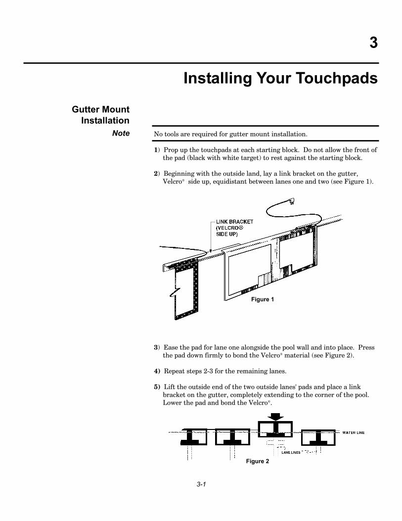
No tools are required for gutter mount installation.
1) Prop up the touchpads at each starting block. Do not allow the front of the pad (black with white target) to rest against the starting block.
2) Beginning with the outside land, lay a link bracket on the gutter, Velcro side up, equidistant between lanes one and two (see Figure 1).
3) Ease the pad for lane one alongside the pool wall and into place. Press the pad down firmly to bond the Velcro material (see Figure 2).
4) Repeat steps 2-3 for the remaining lanes.
5) Lift the outside end of the two outside lanes' pads and place a link bracket on the gutter, completely extending to the corner of the pool. Lower the pad and bond the Velcro.
Gutter Mount Installation
Note
3
Installing Your Touchpads
Figure 1
Figure 2

3-2
It is very important that you install all applicable link brackets. Failure toplace brackets between the outside two touchpads and their respectivewalls will result in an objectionable lateral movement of the pads during ameet.
6) Repeat steps 1-5 for the opposite end of the pool if necessary.
The following parts are supplied by Colorado Time Systems:
2 Stainless steel flat wall mounting brackets for each touchpad 2 Stainless steel expansion bolts and 2 expansion anchors with expan-
sion wedges for each touchpad to fit ½" holes 6 Stainless steel ¼ - 20 x ½" mounting bolts
The following tools will be required:
9/16" socket or open end wrench for supplied ¼" x 20 bolts Socket or open end wrench for bolts Drill motor with ½" masonry bit to fit anchors Hammer
1) Mount two wall brackets to each touchpad, one on each end, using the supplied ¼" - 20 x ½" stainless steel mounting bolts. The mounting brackets are pre-drilled and tapped.
2) Place one touchpad in the pool with the pad flush against the pool wall and centered in the swimming lane.
3) Once the pad is aligned, mark and drill a hole 1½" deep in the pool deck at each bracket hole location.
4) Insert narrow end of expansion wedge into the bottom (serrated end) of the expansion anchor as far as you can easily push it.
5) Place expansion anchor in the drilled holes wedge first. The anchor should protrude ½" above the level of the pool deck. Pound the anchor into the hole until it is even with the pool deck. The expansion wedge will force the anchor to expand into the deck to secure the bolt.
6) Bolt the touchpad mounting brackets to the pool deck using the sup-plied ¼ - 20 x 1" stainless steel bolts.
7) Put a number on the back side of each touchpad and always use that touchpad in that lane number to facilitate mounting.
8) Repeat steps 2-5 for the remaining touchpads.
Replacement touchpad brackets are not included with touchpad ordersand must be purchased separately.
Note
Tools & Materials Required for Flat Wall
Mount Installation
To Install Your WallMounted Touchpads
Note

After you have properly installed your touchpads, ensure they are operating properly by following these steps:
1) After you have mounted your touchpads in the water, test each touchpad with your touchpad meter. Working with one touchpad at a time, insert the touchpad plug into the test meter.
2) Have a swimmer trigger (fingertip touch) the touchpad while you observe the meter. The meter should light up completely from left to right indicating that the swimmer closed the switch contacts.
3) Repeat steps 1-2 for the remainder of the pads.
4) Once all the touchpads have been checked using the test meter, insert the touchpad plugs into their corresponding deck plate jacks (see Figure 6) or cable harness pod (see Figure 12).
5) Set your electronic swim timer for a 50-yard race. Reset the timer and start the race using any appropriate starting method. (Ensure your elec-tronic swim timer arms all lanes for the finish).
6) Once all the lanes are armed, have a swimmer trigger the pad in lane one, then lane two and so on until all lanes have been triggered in order. If you have a printer installed, request a printout of finish results by lane order. Without a printer, request a console display of the finish results by lane.
7) Check to make sure that all times were recorded with lane one record-ing the fastest time. If the slowest time was recorded for lane one, check the lane reversal position on your timer.
Your touchpads may require an initial adjustment in their sensitivity. Thisadjustment can be made by either adding air or releasing air from the pad.After you have made all necessary initial adjustments, your touchpadsshould not require any further adjustments.
Note
4-1
4
In-Water Check List

4-2

5-1
This section will assist you in identifying any touchpad problem(s) bylearning to recognize the specific condition and remedy.
Firm pads should feel similar to pushing your fingers into a thick magazine. Spongy pads give the sensation of pushing your fingers into a piece of foam rubber.
Note
Condition Appearance Meter Readings Problem Correction RemarksTouchpad workscorrectly
Touchpad workscorrectly
Timer shows hit for thepad's lane within 15seconds of the start
Timer shows hit for thepad's lane within 15seconds of the start
Venting pad does notcorrect the problem
Venting pad does notcorrect the problem
Feels Firm
Feels Firm
Feels Spongy
Feels Spongy
Feels Firm
Feels Firm
Feels Firm
Feels Firm
While touching padentire bargraph isilluminated
When touchpad is nottouched, bargraphshould not illuminate
While touching padentire bargraph isilluminated
When touchpad is nottouched, bargraph isnot illuminated
While touching padentire bargraph isilluminated
When touchpad is nottouched, bargraph isnot illuminated
While touching padentire bargraph isilluminated
When touchpad is nottouched, bargraph isnot illuminated
No problem
No problem
Too much air inpad
Air pocket may bevisible
Excessive vacuumin the pad, too lit-tle air
If bargraph is illu-minates when nottouched, the pad isshorted.
Cable problem
If bargraphs arenot illuminated,there could bewater in the pad.
Your pad is work-ingcorrectly
Your pad is work-ingcorrectly
If pad works takeno action
If pad "floats" orbecomes less sen-sitive to touch,you will need toevacuate the air
Vent the pad tolet more air in
Vent the pad tolet more air in
Inspect cable
Contact CTS
Correctly oper-ating padsshould illumi-nate the bar-graph
When the pad isnot beingtouched the bar-graph shouldnot illuminate
See pad evacua-tion inst. sectn 7
See pad evacua-tion instruc-tions, section 7
See pad ventinginstructions,section 7
See pad ventinginstructions,section 7
Wiggle cable atconnector block,plug whileobserving meter
5
Troubleshooting Guide
5-2
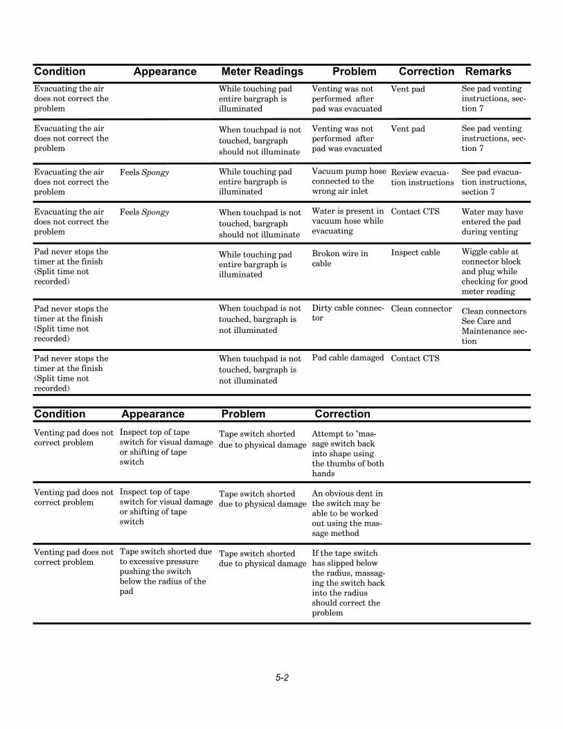
Condition Appearance Meter Readings Problem Correction RemarksEvacuating the airdoes not correct theproblem
Evacuating the airdoes not correct theproblem
Evacuating the airdoes not correct theproblem
Evacuating the airdoes not correct theproblem
Pad never stops thetimer at the finish(Split time notrecorded)
Pad never stops thetimer at the finish(Split time notrecorded)
Pad never stops thetimer at the finish(Split time notrecorded)
Venting pad does notcorrect problem
Venting pad does notcorrect problem
Venting pad does notcorrect problem
Feels Spongy
Feels Spongy
Inspect top of tapeswitch for visual damageor shifting of tapeswitch
Inspect top of tapeswitch for visual damageor shifting of tapeswitch
Tape switch shorted dueto excessive pressurepushing the switchbelow the radius of thepad
While touching padentire bargraph isilluminated
When touchpad is nottouched, bargraphshould not illuminate
While touching padentire bargraph isilluminated
When touchpad is nottouched, bargraphshould not illuminate
While touching padentire bargraph isilluminated
When touchpad is nottouched, bargraph isnot illuminated
When touchpad is nottouched, bargraph isnot illuminated
Tape switch shorteddue to physical damage
Tape switch shorteddue to physical damage
Tape switch shorteddue to physical damage
Venting was notperformed afterpad was evacuated
Venting was notperformed afterpad was evacuated
Vacuum pump hoseconnected to thewrong air inlet
Water is present invacuum hose whileevacuating
Broken wire incable
Dirty cable connec-tor
Pad cable damaged
Attempt to "mas-sage switch backinto shape usingthe thumbs of bothhands
An obvious dent inthe switch may beable to be workedout using the mas-sage method
If the tape switchhas slipped belowthe radius, massag-ing the switch backinto the radiusshould correct theproblem
Vent pad
Vent pad
Review evacua-tion instructions
Contact CTS
Inspect cable
Clean connector
Contact CTS
See pad ventinginstructions, sec-tion 7
See pad ventinginstructions, sec-tion 7
See pad evacua-tion instructions,section 7
Water may haveentered the padduring venting
Wiggle cable atconnector blockand plug whilechecking for goodmeter reading
Clean connectorsSee Care andMaintenance sec-tion
Condition Appearance Problem Correction

5-3
Pad shorts showing a constant finish during the race
Only attempt if you do not have time to make the normal touchpad testlisted under the Care and Maintenance section.
Take an absorbent towel and your touchpad needle to the pad. Dry off theend plug using the towel. IMPORTANT: Make sure the cable end of thetouchpad is not splashed or doused with water while the adjustment isbeing made. Insert the needle into the end plug as described under theventing a touchpad, section 7. Insert the needle in the pad and wait 10 sec-onds. Remove the needle.
This procedure should only be attempted if no other means are availableto correct the problem during a race. DAMAGE TO THE PAD MAYRESULT. If this procedure is used, the pad should be carefully tested fol-lowing the meet to insure that too much air was not allowed to enter thepad.
Emergency RepairsDuring a Race

5-4
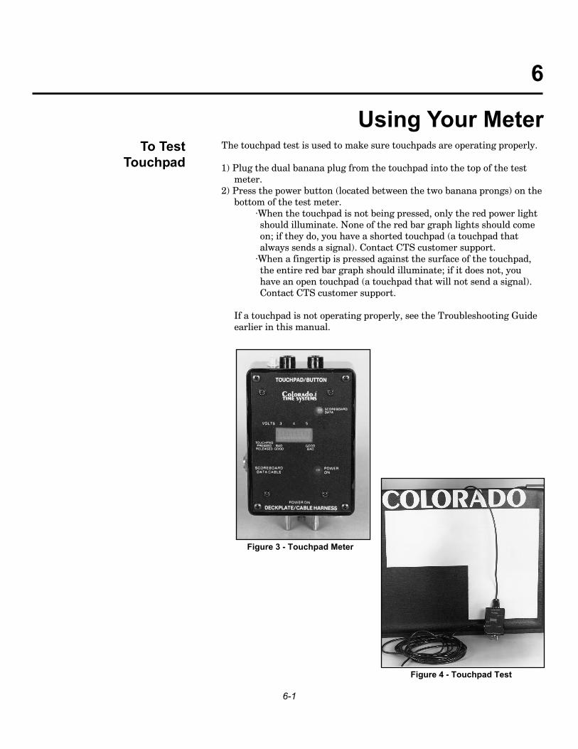
The touchpad test is used to make sure touchpads are operating properly.
1) Plug the dual banana plug from the touchpad into the top of the test meter.
2) Press the power button (located between the two banana prongs) on thebottom of the test meter.
·When the touchpad is not being pressed, only the red power light should illuminate. None of the red bar graph lights should come on; if they do, you have a shorted touchpad (a touchpad that always sends a signal). Contact CTS customer support.
·When a fingertip is pressed against the surface of the touchpad, the entire red bar graph should illuminate; if it does not, you have an open touchpad (a touchpad that will not send a signal). Contact CTS customer support.
If a touchpad is not operating properly, see the Troubleshooting Guideearlier in this manual.
To TestTouchpad
6-1
6
Using Your Meter
Figure 4 - Touchpad Test
Figure 3 - Touchpad Meter
To Test Cable Harness
6-2
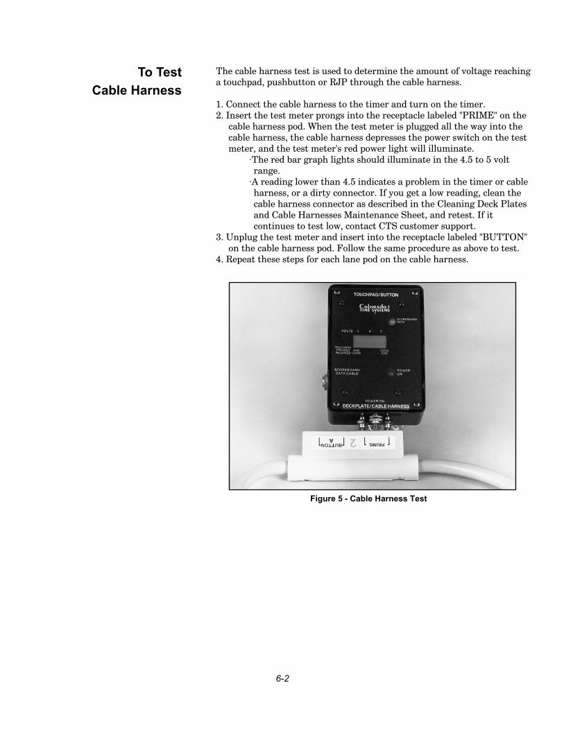
The cable harness test is used to determine the amount of voltage reachinga touchpad, pushbutton or RJP through the cable harness.
1. Connect the cable harness to the timer and turn on the timer.2. Insert the test meter prongs into the receptacle labeled "PRIME" on the
cable harness pod. When the test meter is plugged all the way into the cable harness, the cable harness depresses the power switch on the test meter, and the test meter's red power light will illuminate.
·The red bar graph lights should illuminate in the 4.5 to 5 volt range.
·A reading lower than 4.5 indicates a problem in the timer or cable harness, or a dirty connector. If you get a low reading, clean the cable harness connector as described in the Cleaning Deck Plates and Cable Harnesses Maintenance Sheet, and retest. If it continues to test low, contact CTS customer support.
3. Unplug the test meter and insert into the receptacle labeled "BUTTON" on the cable harness pod. Follow the same procedure as above to test.
4. Repeat these steps for each lane pod on the cable harness.
Figure 5 - Cable Harness Test

The deck plate test is used to determine the amount of voltage reaching atouchpad, pushbutton or RJP through the deck plate or under-block con-nection hub.
1. Connect the timer to the wall plate and turn on the timer.2. Insert the test meter prongs into the "TOUCHPAD" receptacle on the
deck plate. When the test meter is plugged all the way into the deck plate, the power switch on the test meter is depressed, and the test meter's red power light will illuminate.
·The red bar graph lights should illuminate in the 4.5 to 5 volt range.
·A reading lower than 4.5 indicates a problem in the timer or deck plate, or a dirty connector. If you get a low reading, clean the deck plate connector as described in the Cleaning Deck Plates and Cable Harnesses Maintenance Sheet, and retest. If it continues to test low, contact CTS customer support.
3. Unplug the test meter and insert into the "BUTTON A (RJP)" receptacle on the deck plate. Follow the same procedure as above to test.
4. Repeat these steps for the BUTTON B and BUTTON C receptacles.5. Repeat for each deck plate or connection hub.
To Test Deck plates
6-3
Figure 6 - Deck plate
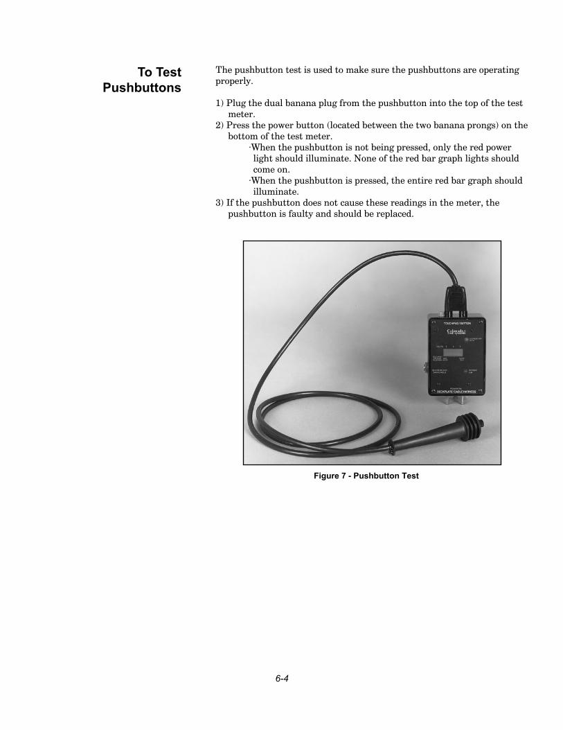
The pushbutton test is used to make sure the pushbuttons are operatingproperly.
1) Plug the dual banana plug from the pushbutton into the top of the test meter.
2) Press the power button (located between the two banana prongs) on the bottom of the test meter.
·When the pushbutton is not being pressed, only the red power light should illuminate. None of the red bar graph lights should come on.
·When the pushbutton is pressed, the entire red bar graph should illuminate.
3) If the pushbutton does not cause these readings in the meter, the pushbutton is faulty and should be replaced.
To Test Pushbuttons
6-4
Figure 7 - Pushbutton Test
If your touchpad always sends a signal to the swim timer, it is "shorted"and may need to have air added (vented) to it. Please consult theTroubleshooting Guide section or call a Colorado Time Systems' CustomerService technician (x256) at (970) 667-1000 or toll-free at 800-287-0653. Ifventing is recommended, follow these steps:
1) Air must be added to a touchpad while it is out of the water.IMPORTANT: Make sure the cable end of the touchpad is not splashed or doused with water while the adjustment is being made.
If air is added to the touchpad while in the water, water may get inside thetouchpad. This will ruin the touchpad.
2) Insert the touchpad plug into the test meter (see Figure 3 and 4).
3) Ensure that the orange rubber plug on the connector block is completely dry (see Figure 9, next page).
4) Remove the needle from its receptacle on top of the touchpad meter. Ensure the needle is free of all burrs (a rough edge that can be removed by drawing the needle across a stone or concrete surface, rotating the needle as you move it).
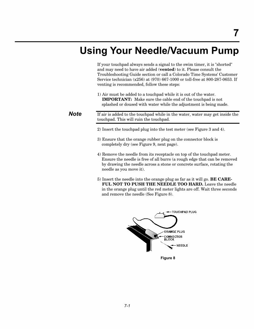
5) Insert the needle into the orange plug as far as it will go. BE CARE-FUL NOT TO PUSH THE NEEDLE TOO HARD. Leave the needle in the orange plug until the red meter lights are off. Wait three seconds and remove the needle (See Figure 8).
Note
7-1
7
Using Your Needle/Vacuum Pump
Figure 8
7) If adding air to the touchpad does not result in the above meter reading,refer to the Care and Maintenance section.
Never handle your touchpads by the cable. This includes when adding airto or releasing air from the pads.
If your touchpad will not send a signal to the electronic swim timer whilefingertip touched, it is "open" and may need to have air released (evacuat-ed) from it. Please consult the Troubleshooting Guide section in this man-ual or call a CTS Customer Service Technician (x256) at (970) 667-1000 ortoll-free at (800) 287-0653 for assistance. If evacuating is recommended,follow these steps:
1) Remove the touchpad from the water.
2) Insert the touchpad plug into the touchpad test meter.
3) Ensure that the orange rubber plug on the connector block is completely dry.
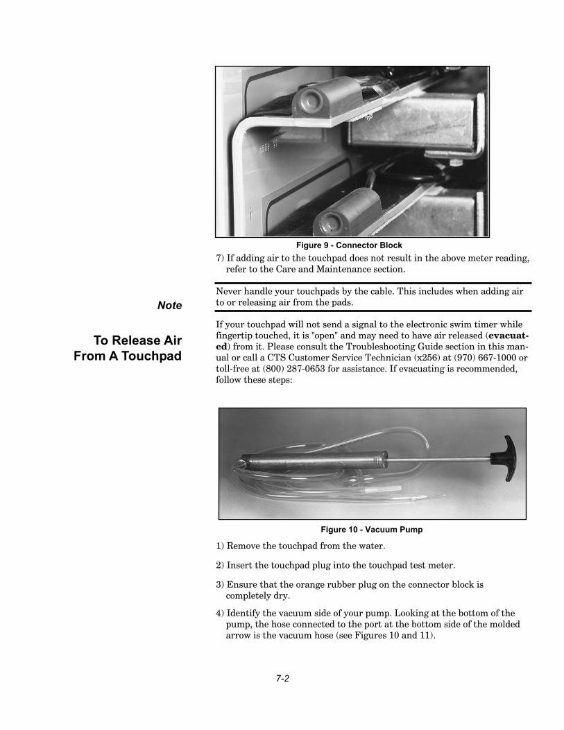
4) Identify the vacuum side of your pump. Looking at the bottom of the pump, the hose connected to the port at the bottom side of the molded arrow is the vacuum hose (see Figures 10 and 11).
Note
To Release AirFrom A Touchpad
7-2
Figure 9 - Connector Block
Figure 10 - Vacuum Pump
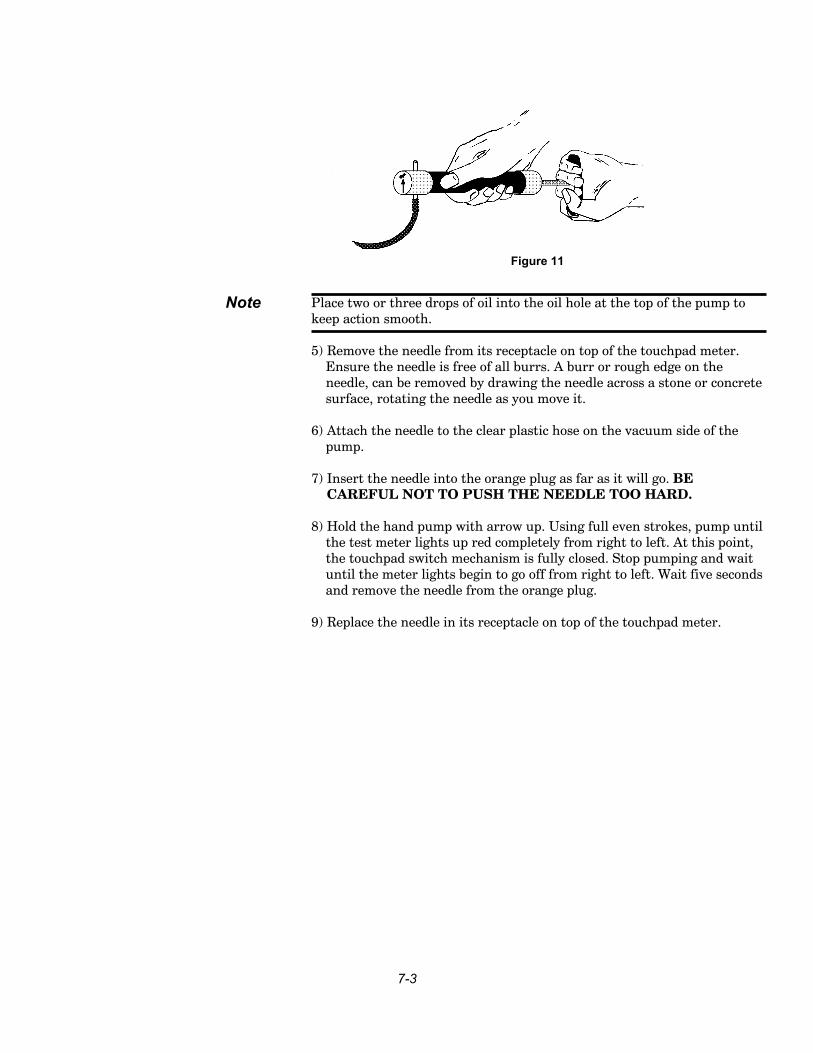
Place two or three drops of oil into the oil hole at the top of the pump tokeep action smooth.
5) Remove the needle from its receptacle on top of the touchpad meter. Ensure the needle is free of all burrs. A burr or rough edge on the needle, can be removed by drawing the needle across a stone or concrete surface, rotating the needle as you move it.
6) Attach the needle to the clear plastic hose on the vacuum side of the pump.
7) Insert the needle into the orange plug as far as it will go. BE CAREFUL NOT TO PUSH THE NEEDLE TOO HARD.
8) Hold the hand pump with arrow up. Using full even strokes, pump until the test meter lights up red completely from right to left. At this point, the touchpad switch mechanism is fully closed. Stop pumping and wait until the meter lights begin to go off from right to left. Wait five seconds and remove the needle from the orange plug.
9) Replace the needle in its receptacle on top of the touchpad meter.
Note
7-3
Figure 11

7-4
8-1
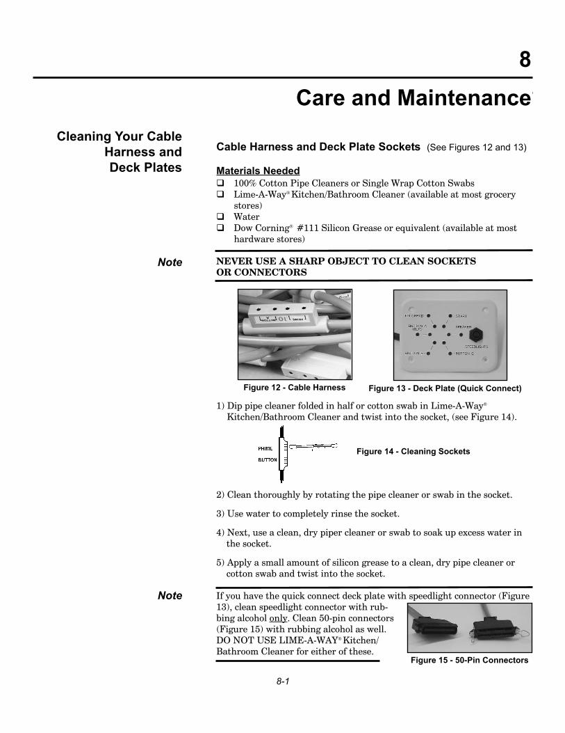
Cable Harness and Deck Plate Sockets (See Figures 12 and 13)
Materials Needed 100% Cotton Pipe Cleaners or Single Wrap Cotton Swabs Lime-A-Way Kitchen/Bathroom Cleaner (available at most grocery
stores) Water Dow Corning #111 Silicon Grease or equivalent (available at most
hardware stores)
NEVER USE A SHARP OBJECT TO CLEAN SOCKETSOR CONNECTORS
1) Dip pipe cleaner folded in half or cotton swab in Lime-A-Way
Kitchen/Bathroom Cleaner and twist into the socket, (see Figure 14).
2) Clean thoroughly by rotating the pipe cleaner or swab in the socket.
3) Use water to completely rinse the socket.
4) Next, use a clean, dry piper cleaner or swab to soak up excess water in the socket.
5) Apply a small amount of silicon grease to a clean, dry pipe cleaner or cotton swab and twist into the socket.
If you have the quick connect deck plate with speedlight connector (Figure13), clean speedlight connector with rub-bing alcohol only. Clean 50-pin connectors(Figure 15) with rubbing alcohol as well.DO NOT USE LIME-A-WAY Kitchen/Bathroom Cleaner for either of these.
Cleaning Your CableHarness and Deck Plates
Note
Note
Figure 14 - Cleaning Sockets
Figure 12 - Cable Harness
8Care and Maintenance
Figure 13 - Deck Plate (Quick Connect)
Figure 15 - 50-Pin Connectors

8-2
Wall Plate Sockets
Materials Needed Toothbrush Rubbing Alcohol
1) Use a toothbrush coated with rubbing alcohol to clean the wall plate (Figure 16) by gently rotating the toothbrush bristles in the over the connection sockets. There is no need to rinse with water because the alcohol will evaporate.
Cleaning Your Wall Plates
Figure 16 - Wall Plate
8-3
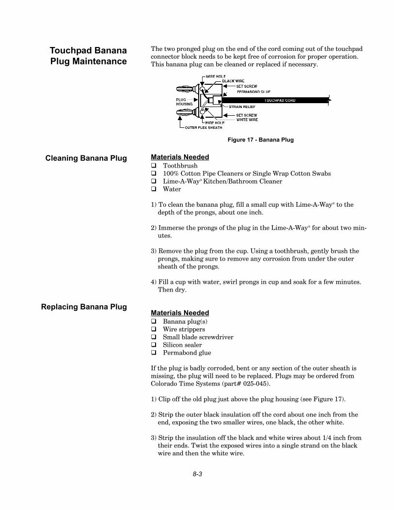
The two pronged plug on the end of the cord coming out of the touchpadconnector block needs to be kept free of corrosion for proper operation.This banana plug can be cleaned or replaced if necessary.
Materials Needed Toothbrush 100% Cotton Pipe Cleaners or Single Wrap Cotton Swabs Lime-A-Way Kitchen/Bathroom Cleaner Water
1) To clean the banana plug, fill a small cup with Lime-A-Way to the depth of the prongs, about one inch.
2) Immerse the prongs of the plug in the Lime-A-Way for about two min-utes.
3) Remove the plug from the cup. Using a toothbrush, gently brush the prongs, making sure to remove any corrosion from under the outer sheath of the prongs.
4) Fill a cup with water, swirl prongs in cup and soak for a few minutes.Then dry.
Materials Needed Banana plug(s) Wire strippers Small blade screwdriver Silicon sealer Permabond glue
If the plug is badly corroded, bent or any section of the outer sheath ismissing, the plug will need to be replaced. Plugs may be ordered fromColorado Time Systems (part# 025-045).
1) Clip off the old plug just above the plug housing (see Figure 17).
2) Strip the outer black insulation off the cord about one inch from the end, exposing the two smaller wires, one black, the other white.
3) Strip the insulation off the black and white wires about 1/4 inch from their ends. Twist the exposed wires into a single strand on the blackwire and then the white wire.
Touchpad Banana Plug Maintenance
Cleaning Banana Plug
Replacing Banana Plug
Figure 17 - Banana Plug
8-4
4) Insert the cord into the strain relief hole on the front of the plug.
5) Using a small blade screwdriver, loosen the two set screws recessed into the top of the plug so that the screw ends clear the wire holes.
6) Insert the end of the black wire into one hole and tighten the set screw. Insert the white wire into the other hole and tighten that set screw.
7) Place silicon sealer in wire holes.
8) Put a drop of permabond glue on the cord just above where it enters the strain relief. Allow to dry for at least one hour.
The Velcro on your touchpads and brackets may become loose or wornand require replacement. The Velcro for the touchpads (the loop, part #580-004) and the brackets (the hook; part # 580-022) and the adhesive(part # 530-010) may be ordered from Colorado Time Systems.
Applying Velcro Adhesive
1) Completely remove the old Velcro and clean the old adhesive off the bracket or touchpad. A latex paint thinner will help loosen any old adhe-sive and allow you to scrape the adhesive off with a putty knife.
2) Apply Velcro adhesive to the bracket or touchpad with a paint brush.Make sure that the width of the Velcro strip is covered with adhesive.
3) Apply the Velcro strip to the bracket or touchpad. Rub down firmly several times or use a small roller to remove any air pockets on the Velcro strip. (Air pockets can cause the adhesive to dry out and the Velcro the loosen).
4) Allow the adhesive to dry overnight.
If you touchpad brackets require replacement, please call our CustomerService Department (x256) at 970-667-1000 or toll-free at 800-287-0653 forordering information.
Velcro Replacement
Note
Properly storing your touchpads is very important to their longevity. Byfollowing the guidelines below, you can reduce the chance of damaging ordestroying your pads.
1) Ensure your pads are stored away from heavy traffic.
2) Hard objects or other touchpads should not rest against the surface ofthe pad or the tape switch located on the 90° angle. Do not expose your pads to the abuse of the table corners, hand rails, door latches or other potentially harmful objects.
3) Touchpads should not be stored in temperatures lower than 50° F or higher than 110° F. If the touchpads are allowed to get too cold, let them soak in the warm pool water for 15-30 minutes before use.
4) Exposure to direct sunlight and/or temperatures over 110° F will result in irreparable damage from sun or heat warpage.
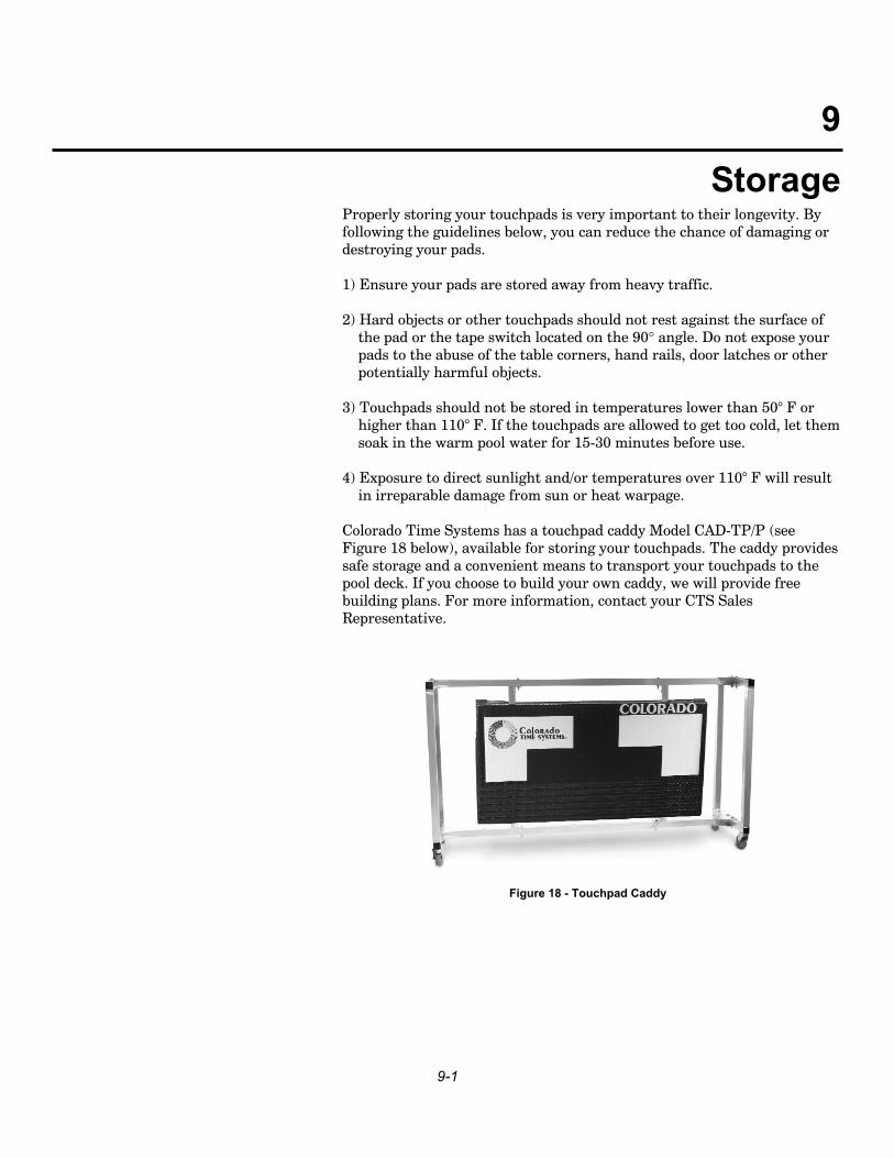
Colorado Time Systems has a touchpad caddy Model CAD-TP/P (seeFigure 18 below), available for storing your touchpads. The caddy providessafe storage and a convenient means to transport your touchpads to thepool deck. If you choose to build your own caddy, we will provide freebuilding plans. For more information, contact your CTS SalesRepresentative.
9-1
9Storage
Figure 18 - Touchpad Caddy

9-2
If you are unable to restore your malfunctioning touchpad to proper operation, please call our Customer Service Department (x256) at 970-667-1000 or toll-free at 800-287-0653. One of our technicians will helpanalyze your system problem and make recommendations for repair.
If it is necessary to return your touchpad(s) to the factory, the technicianwill provide shipping instructions and return authorization information.Make sure any package you send to CTS sufficiently protects the contentsand contains your organization, customer number, name, street addressand daytime phone number.
Normal transit time within the continental U.S. for most carriers is fivebusiness days each way. If you require a quicker turnaround, pleaseinform the technician so they can suggest a faster shipping method.
SHIP TO:Colorado Time SystemsCustomer Service Department1551 East 11th StreetLoveland, CO 80537-5056
Phone: 970-667-1000 x256FAX: 970-667-1032Customer Service: 800-287-0653 x256
10-1
10Servicing Your Touchpads

10-2