CSUS, ECS SENIOR DESIGN, MAY 2015 1 End of Project ...
19
CSUS, ECS SENIOR DESIGN, MAY 2015 1 End of Project Documentation Jonathan Giacomelli, Jonathan Lloyd, Erik Metzner, Jeff Moffet, Anthony Phan Abstract—With an increase in technological growth, one major problem in education is the inability to keep up with the advancements that can benefit school systems. Not only could upgrading school systems save time and money in the long run, it could also increase learning capabilities of students as well. With younger children being exposed to more and more interactive technology each and every day, it would be wise to bring these familiar interactive methods into schools for use in educational purposes. The LightPen team has taken cost effective infrared based interactive whiteboard technology that integrates with other existing resources such as classroom installed projectors and computers, and made it more intuitive for those who are accustomed to traditional chalkboards or whiteboards to interact in an evolving technological environment. This document records the process of designing such a product over the course of two semesters. Keywords—interactive whiteboard, education, presentation, smartboard, digital whiteboard, eLearning, classroom technology, collaboration. CONTENTS I Introduction 2 II Societal Problem 2 III Design Idea 3 IV Funding Proposals 3 V Project Work Breakdown Structure & Project Time Line 4 VI Risk Assessment 4 VI-A Risk Mitigation by Severity Level ... 4 VII Task Assignments 5 VIII User Manual 5 VIII-A Introduction ............... 5 VIII-B Contents ................. 5 VIII-C System Requirements .......... 5 VIII-D Operating System ............ 6 The contributors are students at the Department of Engineering and Com- puter Science, California State University Sacramento. J. Giacomelli is an accomplished Computer Engineer and will graduate in Spring 2015. J. Lloyd is studying Computer Engineering and will graduate in Spring 2015. E. Metzner is studying Computer Engineering and has two years of industry experience. J. Moffet is studying Computer Engineering and will graduate in Fall 2015. A. Phan is studying Electrical Engineering and will graduate in Fall 2015. Manuscript revised April 28, 2015. VIII-E Setting Up Your LightPen ........ 6 VIII-F Setting Up Software ........... 6 VIII-G Using Your LightPen .......... 6 VIII-H Keys and Functions ........... 6 VIII-I Safety Precautions ............ 6 VIII-J Troubleshooting ............. 6 VIII-K Technical Support ............ 6 VIII-L Regulatory Compliance ......... 6 IX Design Documentation 6 IX-A Hardware ................. 7 IX-A1 ATtiny84 ........... 7 IX-A2 MCU 1 ............ 7 IX-A3 MCU 2 ............ 8 IX-B Software ................. 8 IX-C Mechanical ................ 9 IX-C1 The Pen ........... 9 IX-C2 Proximity Sensor Encasement 9 X Test Plan 9 X-A Drawing Resolution Test ........ 9 X-B Concussive Drop Test .......... 10 X-C Communication Path Test ........ 10 X-D Proximity Sensor Test .......... 10 XI Integration Plans 11 XI-A Dual Wiimotes .............. 11 XI-B Diffused IR Emitter ........... 11 XII Conclusion 11 References 12 Appendix A: Acknowledgment 12 A-A Professor Dahlquist ........... 12 A-B Professor Rahimi ............ 12 A-C ST Micro ................. 13 Appendix B: Important Data Sheets and Device Infor- mation 13 Appendix C: Team Member Resumes 13 Biographies 19 Jonathan Lloyd .................. 19 Jonathan Giacomelli ................ 19 Anthony Phan ................... 19 Erik Metzner .................... 19 Jeff Moffet ..................... 19
Transcript of CSUS, ECS SENIOR DESIGN, MAY 2015 1 End of Project ...
CSUS, ECS SENIOR DESIGN, MAY 2015 1
End of Project DocumentationJonathan Giacomelli, Jonathan Lloyd, Erik Metzner, Jeff Moffet, Anthony Phan
Abstract—With an increase in technological growth, one majorproblem in education is the inability to keep up with theadvancements that can benefit school systems. Not only couldupgrading school systems save time and money in the long run, itcould also increase learning capabilities of students as well. Withyounger children being exposed to more and more interactivetechnology each and every day, it would be wise to bring thesefamiliar interactive methods into schools for use in educationalpurposes. The LightPen team has taken cost effective infraredbased interactive whiteboard technology that integrates withother existing resources such as classroom installed projectorsand computers, and made it more intuitive for those who areaccustomed to traditional chalkboards or whiteboards to interactin an evolving technological environment. This document recordsthe process of designing such a product over the course of twosemesters.
Keywords—interactive whiteboard, education, presentation,smartboard, digital whiteboard, eLearning, classroom technology,collaboration.
CONTENTS
I Introduction 2
II Societal Problem 2
III Design Idea 3
IV Funding Proposals 3
V Project Work Breakdown Structure & ProjectTime Line 4
VI Risk Assessment 4VI-A Risk Mitigation by Severity Level . . . 4
VII Task Assignments 5
VIII User Manual 5VIII-A Introduction . . . . . . . . . . . . . . . 5VIII-B Contents . . . . . . . . . . . . . . . . . 5VIII-C System Requirements . . . . . . . . . . 5VIII-D Operating System . . . . . . . . . . . . 6
The contributors are students at the Department of Engineering and Com-puter Science, California State University Sacramento.
J. Giacomelli is an accomplished Computer Engineer and will graduate inSpring 2015.
J. Lloyd is studying Computer Engineering and will graduate in Spring2015.
E. Metzner is studying Computer Engineering and has two years of industryexperience.
J. Moffet is studying Computer Engineering and will graduate in Fall 2015.A. Phan is studying Electrical Engineering and will graduate in Fall 2015.Manuscript revised April 28, 2015.
VIII-E Setting Up Your LightPen . . . . . . . . 6VIII-F Setting Up Software . . . . . . . . . . . 6VIII-G Using Your LightPen . . . . . . . . . . 6VIII-H Keys and Functions . . . . . . . . . . . 6VIII-I Safety Precautions . . . . . . . . . . . . 6VIII-J Troubleshooting . . . . . . . . . . . . . 6VIII-K Technical Support . . . . . . . . . . . . 6VIII-L Regulatory Compliance . . . . . . . . . 6
IX Design Documentation 6IX-A Hardware . . . . . . . . . . . . . . . . . 7
IX-A1 ATtiny84 . . . . . . . . . . . 7IX-A2 MCU 1 . . . . . . . . . . . . 7IX-A3 MCU 2 . . . . . . . . . . . . 8
IX-B Software . . . . . . . . . . . . . . . . . 8IX-C Mechanical . . . . . . . . . . . . . . . . 9
IX-C1 The Pen . . . . . . . . . . . 9IX-C2 Proximity Sensor Encasement 9
X Test Plan 9X-A Drawing Resolution Test . . . . . . . . 9X-B Concussive Drop Test . . . . . . . . . . 10X-C Communication Path Test . . . . . . . . 10X-D Proximity Sensor Test . . . . . . . . . . 10
XI Integration Plans 11XI-A Dual Wiimotes . . . . . . . . . . . . . . 11XI-B Diffused IR Emitter . . . . . . . . . . . 11
XII Conclusion 11
References 12
Appendix A: Acknowledgment 12A-A Professor Dahlquist . . . . . . . . . . . 12A-B Professor Rahimi . . . . . . . . . . . . 12A-C ST Micro . . . . . . . . . . . . . . . . . 13
Appendix B: Important Data Sheets and Device Infor-mation 13
Appendix C: Team Member Resumes 13
Biographies 19Jonathan Lloyd . . . . . . . . . . . . . . . . . . 19Jonathan Giacomelli . . . . . . . . . . . . . . . . 19Anthony Phan . . . . . . . . . . . . . . . . . . . 19Erik Metzner . . . . . . . . . . . . . . . . . . . . 19Jeff Moffet . . . . . . . . . . . . . . . . . . . . . 19

CSUS, ECS SENIOR DESIGN, MAY 2015 2
I. INTRODUCTION
Every generation sees technology come and go throughtheir classrooms, from chalkboards to whiteboard, to overheadprojectors and PowerPoint lessons. This constant evolution ofclassroom tools are designed to make things much more easierand accessible, but some systems fail in that area, insteadcreating more problems.
Every member of Team 8 has horror stories and successstories in their background, from teachers who best utilized thetechnology of the age, to those who terrorized students witharchaic lesson plans. Each of us envisions a world benefited bya technology that helps the flow of ideas, from the instructorto the student in the most efficient and permanent manner.
Through much brainstorming, the team set for the best wayto tackle such a fundamental societal problem. How does onelearn? How best can ideas be expressed? What technologiesare available that augment human capacities in those regards?
We came up with our compass, what was dubbed TheBrainstorm Document, which in various forms is shown below.The LightPen IWB created by Team 8 has followed that coursecharted therein and will undoubtedly surpass the current stateof technology used in education for the generation to come.
II. SOCIETAL PROBLEM
We found in our research that the use of digital content ininstructional settings is becoming more and more popular ifnot the only option in available materials in many instances.One of the difficulties in using digital resources is the abilityto visually interact with them in real time. This loss ofvisual pedagogical methods such as writing on an overheadprojection slide with a dry erase marker is often due to theuse of digital content on a digital projector as teaching aids.While there are technologies available such as InteractiveWhiteboards, these technologies are often not adopted due tolimited budgets, limitations in implementation with existingresources, or difficulty in transitioning into a new workflow.
A big problem in classrooms today is keeping up withtechnology that can help the classroom be more efficientwith time and money. Another problem is the disadvantagedstate visual learners are placed in when the use of digitalresources lacks real time visual interaction. Its also worth whileto point out how those who are presenting the material areoften chained to a computer mouse and keyboard which canlimit their interactive presence in the learning environment.Interruptions to an instructor’s teaching style such as thesecan actually drive them away from adopting such technology.
For a long time now it has become clear that Information andCommunication Technology, ICT, in learning environmentsis necessary for information processing, problem solving andutilizing visualization to be successful [1]. At least one studyhas shown that technical courses such as mathematics aregreatly enhanced when smart technology is implemented inthe classroom [2].
Even though the majority of instructors strive to commu-nicate their understanding on a given topic, students do notalways reach the potential of what is being taught. Thesegaps can be bridged by augmenting the instructor’s efforts
with applicable technology as opposed to previous pedagogicalapproaches [3], [4]. In fact, technologies that encourage inter-action are shown to enhance student and teacher interaction[5] [6] [7]. In one study of undergraduate chemistry courses,it has even been shown to increase student activity. (see figurebelow)
Fig. 1. Activity index, Science Direct
Not all instructors are eager to change their teaching meth-ods to accommodate technological advance. With this in mindit is important for new technologies and implementations toprovide a path to help transition hesitant adopters to use thenew technology [8].
In addition to educational value there are other perks totechnology such as digital whiteboards. For example, dry erasemarker supplies constantly need replenishing. After a while,the whiteboard becomes permanently stained and replacementswill have to be acquired.
Another important consideration is that existing technologyin classrooms may vary widely so technological solutionswould need to be versatile. From a cost effective point ofview, integration with the existing technology would be bene-ficial such that the need for additional supporting technologywould be limited. Also, much of the interactive technologiesavailable are very expensive which limits availability to manyeducational institutions where budgets are limited.
Simba Information published a report a couple of years agoon the different technology used for education, based on thenumber of hours used each day. The gathered data is depictedin the figure below. It is interesting to see that interactivewhiteboards are used very often, which could possibly meanthat students have grown accustomed to using this technology.More so for us, it is interesting to see that the two mainingredients for our system, projectors and desktop computers,are used respectively, 40% and 45% of the day. Integrating oursystem with the existing technology, projectors and desktopcomputers, may not be too much of a hassle.
Technology can help a classroom setting be more interactive,by projecting whatever is on a computer onto the wall, andbeing able to write all over that image. This does not haveto be confined to the classroom, but can also be visualized

CSUS, ECS SENIOR DESIGN, MAY 2015 3
Fig. 2. Use of technology per day to teach ELL students, Academic BusinessAdvisors [9]
in a business setting as well. Business meetings can utilizethis technology and make their Powerpoint presentations moreinteractive, as they never were before.
Technology in learning environments that encourage in-teraction between instructors and students, and that providevisual interaction with presented materials are critical as othereducational technologies move forward. These interactive tech-nologies need to take account of the needs of instructors aswell as limited budgets of schools. Those of us in Team 8will tackle these shortcomings in our LightPen design, whichbrings us to the discussion of our design idea.
III. DESIGN IDEA
We took our solution to create a better interface between theknowledgeable and those who seek knowledge and found thebest way to summarize our idea was with this elevator pitch:The learning environment is strained by poor transmissionof ideas from instructor to student; This can be improvedusing superior tools such as the following proposed digitalwhiteboard.
Our idea is to create a pen, that fires an IR led when theuser is writing, ie. when the pen is close to the board. TheIR leds movements will be captured by the Pen LocationSystem. Other information such as color changing and erasingcan be transmitted by the pen to the Pen Location System aswell. This information that is being transmitted by the penwill be relayed to the View. The View is a piece of softwarethat writes when the user is writing, and changes color whenthe user wants to write in a different color, and so on. Bymoving traditional teaching methods towards digital means,this enables both teachers and students to be more interactivewith class material and help foster educational improvements.
We designed a featureset that best encompasses the flowfrom the instructor, through the technology, and to the student,which is listed below in our abridged punchlist:
– The Pen will detect proximity to a flat surface• Outcome: The Pen will detect when it is close to a
flat surface, and will detect when the Pen has movedaway from the surface.
– The Pen will emit IR when close to a flat surface• Outcome: The Pen will be able to emit IR, given the
successful detection of the previous feature. The Penwill not emit IR without the detection signal.
– The Receiver will receive IR• Outcome: The Receiver will detect the IR signal and
pass that data to the View.– Given the IR received, The Receiver/View will determine
the X,Y coordinate of The Pen near the flat surface.• Outcome: When the Pen is close enough to the flat
surface, the View will be able to determine where thePen is on the flat surface.
– The Receiver/View will change display on the flat sur-face, drawing lines• Outcome: The View will draw on the flat surface
where the Pen is present.– The View will be able to have different colors and be
able to erase• Outcome: The View will draw in the correct color, to
include erasing.– The Pen will take user input to determine
draw/color/erase state.• Outcome: The User will be able to change the color
of what is written or be able to use erase mode, byonly having to interact with the Pen in some way.
We focused on the realizable physical phenomenon thatwill occur using our technology, so that we would have themost flexibility to solve such a complex problem and reallyplunge into the depths of all possible solutions. Using these,we matched each section within our brainstorm document, toproduce a number of tasks. Each of us at Team 8 eagerlysigned up for and tackled those tasks with vigor. With all ofthe excitement about our new project, it was easy to work onour new Lightpen, but paying for our new project didnt comeas easy.
IV. FUNDING PROPOSALS
When we decided to switch projects we talked briefly abouthow we would fund the project without Wijit’s help. I thinkwe discussed each of us kicking in $70 maybe more or less.Anyway, Erik has been buying a lot on his own that I feelhas been very useful toward the project, as well as donating alot of his previously acquired items such as MCU/diodes etc.Each of us have pitched in here and there as well. I feel like weneed to get a dialog going on budget, and what we expect/wantto contribute. Then have a way to tag team purchases that wewant to make.I feel like Erik is in a little deeper than he should be, andI’ve set aside a $20 emergency relief fund, cash, in my walletfor the next time I see him. After we all get a chance to talkabout funding a little more I’m willing to send a little morehis way if needed. At any rate I plan to be more involvedin future purchases. Before we even had all of the fundingdetails figured out, we were going full speed ahead into thework breakdown structure and project timeline.

CSUS, ECS SENIOR DESIGN, MAY 2015 4
V. PROJECT WORK BREAKDOWN STRUCTURE &PROJECT TIME LINE
Below is our infamous Gantt Chart. This details each of thetasks in the brainstorm document and attaches both a Resource(aka a member of Team 8) and a timeframe to ensure allfeatures are being given their due processing.
Fig. 3. Project Work Breakdown Structure & Project Timeline
The details of the Gantt Chart will be fully displayed inthe Task Assignments section of this document. We have metnumerous times and had lengthy discussions to ensure allteammates are on the same page and have a clear understand-ing of each member’s ideas. We have instituted a number ofskilled communication techniques to expedite and parallelizethese discussions, and we were able to produce a well formeddocument that describes all known tasks. Some tasks are notknown, either because the precluding research tasks are still inprogress, or because they depend on other tasks and modulesto be complete before the research can begin in earnest. Eitherway, these unknowns have also been described below to ensurethat they are recognized and properly addressed when the timecomes, and so that no evolution or process gets lost in thecracks.
Below is a simplified chart of our work breakdown structure.Each feature is divided into six steps. First research, thenprocure necessary parts, breadboard, PCB, software coding,and finally integrating each component into the final product.Each step was divided among our team members, based ontheir interests and skill set.
Even with all of the skills that we, as a team, possess,Murphys Law and several other issues still exist that couldhamper the progress of our project; Thus, we must evaluatethe risks.
VI. RISK ASSESSMENT
Considering risk was part of our planning early on inthe project, especially when planning the Work BreakdownStructure (WBS). The team generally had a good handle onindividual priorities and dealing with the associated risks. Oneof the big priorities for some team members were family lifeas they were expecting children. Involvement from these team
Fig. 4. Work Breakdown Structure
members in the WBS was minimized during the time directlyafter their new children would arrive. Everyone had the taskof balancing this project with other projects, class work, andexams. Part of mitigating these risks was creating a GoogleCalendar which integrated detailed individual schedules andavailabilities. This made it possible to make the best schedulingdecisions, especially if they needed to be made quickly.
The team needed to anticipate risks such as equipment beinglost, or a crucial project component being damaged. Perhapswe could experience a problem with software tools after it isupdated. All of these were considered when determining thepriority of tasks, and subtasks such as ordering parts. Morecritical tasks were scheduled early so that if there were anyemergencies there would be time to take corrective action.Also, emphasis on ordering parts early before they were neededwas made to reduce wait time as much as possible. Anothercritical point was to order extra parts.
A. Risk Mitigation by Severity Level◦ Green:
• Work, other school related demands◦ Team member schedule on Google Calendar gives
visibility of potential time demand conflicts so thattasks are prioritized to reduce conflicts•One team member is given a task instead ofanother team member because the other teammember has heavy time demands that wouldlimit the amount of time they would have towork on the task causing delays.
• Sick or injured team member◦ Team members keep in communication about what
they are doing, and if they need help completinga task.
◦ Yellow:• Equipment breaking/lost
◦ Have extra tools on hand.• Senior Design assignments
◦ Order parts early so that they are in transit whilewe are working on documentation assignments.
◦ Red:• Part lost/broken/inadequate

CSUS, ECS SENIOR DESIGN, MAY 2015 5
◦ Have extra parts on hand◦ Do small test cases, and have backup plans
•Build small breadboard proofs of features beforeintegrating them into the complete system.
• Technical difficulties◦ Make sure there is time planned for setting up tools
such as IDEs etc.• Insufficient Funds
◦ Budget◦ Factor in time to fabricate parts such as the en-
closure from existing resources such as pens andmarkers.
• Physical system damage/accident◦ Have extra parts on hand◦ Take a modular approach such that integration of
features into a complete system do not use theparts from the breadboard proof which can be usedas a backup.
• Family emergencies◦ Plan for team members that are expecting children
to be less involved when the time comes.◦ Plan for more than one team member to be in-
volved in any given task for redundancy.
Fig. 5. Risk Assessment Chart
Now that we have a better understanding of the many risksthat are involved in completing this project in a timely manner,we will exercise more diligence in how we assign the multitudeof tasks that are required for this project.
VII. TASK ASSIGNMENTS
The hours spent on tasks are shown in the Task and TeamMember Hours Distribution Table. The hours reported herebring attention to the point that we did change projects inweek eight which causes our hours to be less than wouldbe expected. However, the following considerations should bemade:
• Many of the efforts that we had put toward the previousproject were transferable, such as research for MCUselection.
• For such tasks as documentation, we were equipped withextra experience the second time around, to the point thatwe were able to be much more productive in a shortamount of time.
Fig. 6. Task and Team Member Hours Distribution Table
With this understanding tasks have been summarized byfeature for easier reading and now we come to the User Manualfor more specific information about our project.
VIII. USER MANUAL
A. IntroductionThank you for using the LightPen as part of your In-
frared(IR) based Interactive Whiteboard(IWB) solution. TheLightPen is designed to IR IWB usage intuitive for thoseaccustomed to traditional whiteboard, and additionally offerfeatures that take advantage of what IWBs have to offer.
B. Contents• LightPen• User Guide• (Optional) USB Receiver
C. System RequirementsHardware• Wiimote (or other IR Positioning Human Interfacing
Device) connected to PC• USB port for optional USB ReceiverSoftware• gtkWhiteboard• Ardesia

CSUS, ECS SENIOR DESIGN, MAY 2015 6
D. Operating System
Linux
E. Setting Up Your LightPen
Carefully open the battery compartment, remove the batteryholder, and insert batteries into the battery holder while fol-lowing the positive and negative battery symbols. Insert thebattery holder in the direction the arrow points on the batteryholder.
F. Setting Up Software
Obtain a copy of gtkwhiteboard and follow their instructionsfor installing it on the computer you will be using the LightPento interact with:http://www.stepd.ca/gtkwhiteboard/
Also, install the overlay software Ardesia found here:https://code.google.com/p/ardesia/
G. Using Your LightPen
First, the LightPen activates when the writing tip is withina certain distance to the screen. This distance can be slightlycustomized by putting the tip near the screen and pressing thecalibrate button on the LightPen when youre comfortable withthe distance. Always make sure that the Wiimote has a clearview of the writing tip of the LightPen when you expect it tobe active.Now, lets proceed.Make sure the LightPen is calibrated to activate when desired.Position the Wiimote so that it has a clear view of video displaywhere the LightPen will be used.Launch gtkwhiteboard.Press 1 & 2 button on Wiimote, then click Start in gtkwhite-board to begin the calibration.Activate the LightPen at the four corners of the screen, asdirected by gtkwhiteboard.Once successful calibration is complete, the LightPen will beready for use in Ardesia.Launch Ardesia and begin using the LightPen.
H. Keys and Functions
Fig. 7. Key Feature Map
1 Laser Button Turns pointing laser on and off.
2 Calibrate Button With the LightPen near the writing surface this buttonsets the current position as the distance to the surfacewhen the LightPen should activate.
3 Next Button (Optional with USB Receiver and software)
4 Back Button (Optional with USB Receiver and software)
5 Communication Light This part of the pen needs to be visible to the Wiimoteor similar device when attempting to write with theLightPen
6 Laser Pointer Laser beam is goes in the direction of the arrow. DONOT LOOK DIRECTLY AT THE LASER BEAM
7 Writing Tip The LightPen’s writing tip needs to be visible by theWiimote or similar device while attempting to writewith the LightPen
8 Color Change (Optional with USB Receiver and software) Changesthe color of the line
TABLE I. KEY FEATURES EXPLANATION
I. Safety Precautions• Make sure you always have a firm hold on the LightPen.• Never point the laser at a person or pet. Do not look at
the laser directly or with any optics like binoculars or amagnifying glass.
• Keep the LightPen out of reach of children.• Do not attempt to repair or alter the LightPen.
J. TroubleshootingI’m not able to write on the screen, or the writing is
intermittent. . .Make sure of the following:• The yellow light flashes once when the LightPens writ-
ing tip is close to the screen.• The batteries are fully charged.• The calibration button on the LightPen has been pressed
with the writing tip of the LightPen close to the screen.• There is nothing blocking the Wiimotes view of the
writing tip of the pen at any time.• The Ardesia overlay software is running, the Wiimote
has been connected to the computer and has beencalibrated.
K. Technical SupportEmail: [email protected]
L. Regulatory ComplianceThis device complies with Part 15 of the FCC Rules.
Operation is subject to the following two conditions: (1) Thisdevice may not cause harmful interference, and (2) This devicemust accept any interference received, including interferencethat may cause undesired operation.
IX. DESIGN DOCUMENTATION
The design documentation consists of the system hardwareand software . Block diagrams, hardware and software descrip-tions will be discussed.

CSUS, ECS SENIOR DESIGN, MAY 2015 7
Fig. 8. LASER RADIATION–DO NOT STARE INTO BEAM OR VIEWDIRECTLY WITH OPTICAL INSTRUMENTSCLASS II LASER PRODUCT
A. Hardware
For clearer purposes of describing the hardware design, ablock diagram will be used. There are two block diagramsdue to using two separate microcontrollers. The use of twomicrocontrollers were chosen due to the number of useablepins (12 pins). MCU1, figure 9, controls the front endcomponents of the pen, and MCU2, figure 10, controls theback end components of the pen.
MCU1• Laser Diode: A common red laser pointer.• Proximity Sensor: A sensor to detect when the pen
is near the board to allow the user to write. Once inproximity, the MCU will turn on the IR LED.
• Indication LED: A yellow LED to indicate to the userthat the pen is in proximity and can begin writing. . . .
• IR Output: An IR LED that will be turned on for theWiimote to track.
MCU2• Radio: Communication between the pen and computer,
mainly for color changing purposes.• Rotary Encoder: User input device to change between
colors.• RGB LED: RGB diode for user to see which color has
been selected.1) ATtiny84: The chosen microcontroller for the system is
an ATtiny84 and seemed the right choice due to its size andachievable speed. It could easily be soldered onto a pcb andfit into the pen without taking too much room. The ATtiny84has built in ADCs which has a resolution of 5 volts mappedto 1024 units and can be ran up to 20 Mhz [10], well aboveour range of desired speed. One ADC pin (pin 9) was used forMCU1 and the other useable pins were used as either strictlydigital output pins or analog output (PWM) pins. A pinout ofof the ATtiny84 is depicted in figure 11.
2) MCU 1: As stated before, MCU1 controls the compo-nents at the front end of the pen. This consists of the proximitysensor, red laser pointer and an indicator LED as shown infigure 12.
Fig. 9. MCU 1
Fig. 10. MCU 2
Fig. 11. ATtiny84 pinout [10]
Red laser pointer - The laser pointer is a common tool thatteachers use to catch students attention. As such, it seemedappropriate to add it into the system. This is not tied in withthe MCU, but is controlled by a simple push button switch.The Laser pointer is labeled LaserDiode1 in figure 12.
Indicator LED - The indicator led is a visual cue for theuser that they are close enough to the surface to begin writing.When the user holds the pen up close to a surface, the LEDindicator will turn on for a second and then turn off, lettingthem know that the pen is activated for writing. The LED usedis the TLCs5101, a 5mm yellow LED. The indicator is labeledLED3 in figure 12.
Proximity Sensor - The proximity sensor will detect whenthe pen is held close to the surface. It is designed by having

CSUS, ECS SENIOR DESIGN, MAY 2015 8
one LED forward biased, and the other reversed biased. Theforward biased LED has its anode connected to the MCU,and will be sending constant pulses through pulse widthmodulation. This is pulsing LED is labeled LED1 in figure12. The second LED, labeled LED2, has its cathode connectedto the supply rail. When it sees the pulses from LED1, avoltage will be created at LED2s anode. This output voltageis connected to the ADC (pin 9) of the MCU as seen in theMCU1 circuit.
IR LED - The IR LED will output the infrared light thatthe Wiimote will catch and follow as the user is writing aboutthe surface. The IR LED used was the TSAL4400, a 3mm IRLED. This IR LED has a maximum forward current of 100 mA[11], well above what the MCU can output. To overcome this,a switching MOSFET was used with the gate being controlledby the MCU. The IR LED is labeled IrED1 in the MCU1Circuit.
Fig. 12. MCU1 circuit
3) MCU 2: MCU2 controls the components at the front endof the pen. This consists of the rotary encoder, RGB LED, andthe radio as shown in figure 13.
Rotary Encoder - The rotary encoder acts as a user inputdevice to change the color the user is writing in. The rotaryencoder is mapped for eight different colors, red, orange,yellow, green, blue, purple, white, and black. Earlier stagesof the pen utilized a potentiometer, but was replaced by therotary encoder, due to its ability to swing full 360 degreeswithout having to backtrack to zero. The rotary encoder islabeled RotEncoder in figure 13.
RGB LED - The RGB LED is a four pin common cathodeLED, labeled LED4 in figure 13. Its purpose is to give theuser visual cues of what color they have chosen. In order tochange colors of the LED correctly, the RGB pins had to beconnected to the designated PWM pins of the MCU.
Radio - The radio takes the input from the rotary encoderand communicates that information to the Ardesia software.The radio takes the most pins of MCU2 (pins 6-10), and islabeled Radio Reserved 1-5.
B. SoftwareAs the User interacts with the LightPen hardware, code
running on the embedded microcontroller sends data via serialbus to an embedded radio. A second radio is paired to theone in the PEn and is attached the the PC, which uses an API
Fig. 13. MCU1 circuit
Fig. 14. Software Relational Diagram
to convert that received USB data from the radio into hotkeypresses. Shown below is where the driver software currentlyfinds the double click state in touchpad mode, changing thesignals sent from simple mouse position, to a left-click helddown plus the mouse’s position used to draw in the overlaysoftware.
Fig. 15. Double-Click code override section
We send those Hotkeys to the overlay software through theexisting OS of the PC. Since both driver and overlay softwaresare Open Source and Multiplatform, this should be useable byall OSs. We are currently developing in Ubuntu 14.04, withtesting occurring simultaneously in Windows 7. We extendedthe overlay software to receive the Hotkeys we choose, and

CSUS, ECS SENIOR DESIGN, MAY 2015 9
purposefully chose extremely non-standard combinations toprevent clashing with other major software suites.
C. Mechanical
The mechanical component of the system consisted of thephysical encasement of the pen. Through many iterations, thefinal pen is now built using pvc pipe and custom 3D printedpieces for the end caps and a tray for buttons to be mounted,as well as holders for each PCB.
1) The Pen: The pen body is created from a inch diameterpvc pipe purchasable from a local hardware store. The lengthof the pipe is 9 inches long. A portion of the pvc pipe wascut out and a 3D printed piece was created to be mounted inthe cut out portion. This 3D printed piece was designed toeasily mount the buttons on a flat surface, rather than a curvedsurface. This can be seen in figure 16.
Fig. 16. Button tray with and without cover
Two other printed pieces were created for the front endand back end of the pipe. The front end, figure 17,houses theproximity sensor, the laser diode, IR LED, and an indicatorLED. The back end printed piece, figure 18, houses the rotaryencoder and RGB LED.
Fig. 17. Pen front end
Fig. 18. Pen back end
Each PCB in the pen has a custom 3D printed capsule,figure19, to protect its circuit from outside damage due fromdropping, dust, etc. Each capsule has slots for wire connec-tions.
Fig. 19. Pen back end
2) Proximity Sensor Encasement: The front end of the penhouses the proximity sensor, a major feature of the project.Multiple prints were designed for testing the various anglesbetween the two LEDs to find a satisfactory angle. Findingthe correct angle between the two LEDs to detect the rightdistance for the user to begin writing is very important. If theangle between the two were too large, the LED would reflectback into the other at a closer distance such as figure 20a.The IR LED may not turn on at all for the pen could possiblyobstruct reflection back into the proximity sensor. If it weretoo small, such as figure 20b, the LED would reflect back intothe other at a farther distance which would turn on the IR LEDat a farther distance. An optimal angle would be one that doesnot detect at a large distance, but also not too close, such asfigure 20c. Through testing and multiple 3D printed pieces tohold the two LEDs at specific angles, it was found that 10degrees between the two were optimal for our case.
Fig. 20. Proximity sensor angles
X. TEST PLAN
To ensure a working product, the product should be putunder as many relevant tests as possible. Having a test plan fora product is highly important, not only to see if it is functional,but to see if it performs consistently in many settings andsituations. Tested factors included, but were not limited to,the Wiimotes position as it pertains to angle and occlusion,the Wiimotes effect on display quality in terms of its distancefrom the screen, and light interference on the proximity sensorof the pen.
A. Drawing Resolution TestThe purpose of this test was to maximise the hardware and
software related to drawing such that The Pen draws into thescreen as close to the performance of a real whiteboard pen( inch resolution) on a surface approximately as large as aregular whiteboard surface (4ft tall x 8ft wide). The resolutionis restricted to the Wiimotes IR camera. In some cases, maybeto due to a faulty Wiimote, or perhaps a counterfeit one,drawing straight lines ended up being jagged and pixilated

CSUS, ECS SENIOR DESIGN, MAY 2015 10
Test 1 Front End Cap Back end cap Button Cover Functionality
Vertical secure Secure Seperated FunctionalHorizontal secure Secure Seperated FunctionalTest 2 Front End Cap Back end cap Button Cover Functionality
Vertical secure Secure Seperated FunctionalHorizontal secure Secure Seperated FunctionalTest 3 Front End Cap Back end cap Button Cover Functionality
Vertical secure Secure Seperated FunctionalHorizontal secure Secure Seperated Functional
TABLE III. DROP TEST RESULTS
as seen in figure 21.This test was carried out by attempting to draw the smallest
square possible on the screen. The goal of this test was todrive the area of the square so low that it is comparable to awhiteboard marker, and is equally difficult to measure. If thesquare is too small to measure using a common ruler, then therequirement is met. Otherwise, the area of the smallest possibledrawn square was logged. These squares are also depicted infigure 21.
Fig. 21. Jagged lines due to poor resolution
During this test it was found that the resolution was approx-imately the same as tests before in the previous semester. Aftertroubleshooting, it was found that if the IR LED was aimeddirectly back towards the wiimote, instead of reflecting off thesurface, the resolution became far better, as shown in the testresult in table II.
After some investigation, it was found that the IR LEDwas drawing approximate 30mA, which is much less than theanticipated 100mA. It was concluded that the IR LED wasnot emitting at full brightness and has been causing problemsfor the IR camera in the wiimote to detect. By running theIR LED at its maximum forward current, better results wereobserved in terms of resolution.
B. Concussive Drop Test
The concussive drop test examined the physical durabilityof our product. The pen was held a meter high above the floorand dropped onto the ground both in a vertical position andhorizontal position. The use of 3D printed pieces to hold allthe components resulted in a much more durable product. Thetest was ran three times and through each one, both the frontand back end caps were intact. The button cover was separatedfrom the tray after each test. Results are displayed in table III.
Run # Pen Angle Occlusion Pass/Fail
030915-01 30 Full Fail030915-02 30 Partial Fail030915-03 30 None Pass030915-04 45 Full Fail030915-05 45 Partial Fail030915-06 45 None Pass030915-07 60 Full Fail030915-08 60 Partial Fail030915-09 60 None Pass
TABLE IV. PEN ANGLE AND OCCLUSION RESULTS
C. Communication Path Test
The purpose of this test was to ensure that the Pen and thePC running the overlay software can communicate, meaningthat the Wiimote does in fact see the IR LED emitting from thepen. The procedure was simple, the software and Wiimote wereset up and drawing was attempted. If the Wiimote detects theIR LED and the able to draw in the software, this resulted ina pass. The test results showed that the the software functionscorrectly and the Wiimote does in fact detect the IR LED.
D. Proximity Sensor Test
This test examined the different factors and elements thatthe proximity sensor would be subjected to. Factors includedwere the material that the LEDs would be reflecting off of,the angle between the two LEDs and the ambient light in theroom.
The angle between the two LEDs were tested at 6, 8, and10 degrees. Using the 10 degree angle between the two, theproximity sensor produced a maximum of roughly 1.2V. Thismaximum signal occurred at about an inch away from a flatsurface. The 6 and 8 degree test produced a 1V maximumat a closer distance. For practicality the 10 degree angle waschosen because the front end of the pen where the proximitysensor lays could possibly obstruct the proximity sensor fromdetecting a surface at all and also produced a much highersignal.
Another test was ran to see at what angle the user holds thepen to the surface. This is to mimic the size of a whiteboard,where users will have to hold the marker high above therehead and possibly at an acute angle. This is to take accountthat the user will not be holding the pen perpendicular to thesurface at all times.
Using the 10 degree angle between the two LEDs, it wasfound that the user can hold the pen to at least 60 degreesto the surface. Any higher than that, and depending on thematerial of the surface, the proximity sensor can have troubledetecting closeness. Occlusion was accounted for and it wasfound that the Wiimote needs a direct line of sight of the IRLED in order to detect the infrared light. Results are depictedin table IV.
The material that the user writes on plays a big factor on theproximity sensors ability to reflect its light back into itself. Ifthe user writes on a glossy material such as a computer screen,the light does not reflect back very well and the proximitysensor did not produce usable signal very well. This test wasdone on a laptop screen. Materials that do not absorb light are

CSUS, ECS SENIOR DESIGN, MAY 2015 11
Run # Screen Size (in x in) Wiimote Distance (in) Wiimote Angle (deg) Lighting Hand Resolution (area in2̂)
030915-01 117x66 166 82 fluorescent right 10.5030915-02 117x66 166 82 fluorescent right 1.44
TABLE II. DRAWING RESOLUION TEST RESULTS
Material Rating (1 least optimal, 5 most optimal)
Glossy Screen (laptop, tv, etc...) 3Matte Screen (laptop, tv, etc) 4Canvas Screen 5White painted wall 5
TABLE V. SURFACE MATERIAL RESULTS
much better for our product. Testing on the pull down screenat the front of the senior design room worked very well. Thelight was able to reflect back and there were no problems withdetecting closeness to the screen. Table V depicts results forsurface material.
The ambient light in the room also plays another factorfor our proximity sensor. In the MCU code, the threshold forsensing proximity at the highest to remove ambient light. Thismeans that light from the proximity sensor can only activateitself. However, if the proximity sensor is pointed directly atlight source, it has a tendency to think that it is detectingproximity. This test was ran in both darkened and fully litrooms and was successful through both.
XI. INTEGRATION PLANS
This section considers possible solutions to problems thatwere found during testing.
A. Dual Wiimotes
Testing showed that there was a problem with resolutionon larger displays. This lead us to find that the Wiimotes areactually rather low resolution. One potential solution we foundwas HID driver software for the Wiimotes that allows twoWiimotes divide the display which effectively increases theresolution as shown in figure 22. By having two Wiimotes, afiner resolution can be obtained, as well as the user not havingto deal with being in the line of sight between the Wiimoteand the IR LED.
Fig. 22. Dual Wiimote concept
B. Diffused IR EmitterAnother course of testing found that using a diffused IR
source for the Wiimotes to track created more consistency.This is because alternative methods such as tracking the lightfrom the emitter shining on the display may be inconsistentdepending on the reflectivity of the surface. A reflective surfacecan cause the IR light to bleed outwards on the surface andcause confusion to what the Wiimote is seeing. As concludedin table V, a less reflective surface is the most optimal. The IRlight does not bleed out as much and is kept in a finer circleon the surface. One solution to create diffused IR emissionwould be to create a small window of infrared light onto thepen, so that it could be seen from any angle and position, asshown in figure 23.
Fig. 23. IR window concept
XII. CONCLUSION
Through two semesters and a ton of hours put into thisproject, we are confident to say we have a system that cancompete with current implementations of digital whiteboardsand allow the instructor and the student to communicate farmore effectively than previous technologies have allowed.Each member of Team 8 has shown the desire and capability totake this technology from its current state, into a more full andrealized version by the end of the year. Each generation seesthis a change in technology, and our LightPen IWB is at theforefront of the next generation of technologies that empowerlearning!
CSUS, ECS SENIOR DESIGN, MAY 2015 12
LIST OF TABLES
I Key Features Explanation . . . . . . . . . . . . . 6III Drop test results . . . . . . . . . . . . . . . . . . 10IV Pen angle and occlusion results . . . . . . . . . . 10II Drawing resoluion test results . . . . . . . . . . 11V Surface material results . . . . . . . . . . . . . . 11
LIST OF FIGURES
1 Activity index, Science Direct . . . . . . . . . . 22 Use of technology per day to teach ELL students,
Academic Business Advisors [9] . . . . . . . . 33 Project Work Breakdown Structure & Project
Timeline . . . . . . . . . . . . . . . . . . . . . . 44 Work Breakdown Structure . . . . . . . . . . . . 45 Risk Assessment Chart . . . . . . . . . . . . . . 56 Task and Team Member Hours Distribution Table 57 Key Feature Map . . . . . . . . . . . . . . . . . 68 LASER RADIATION–DO NOT STARE INTO
BEAM OR VIEW DIRECTLY WITH OPTICALINSTRUMENTSCLASS II LASER PRODUCT . . . . . . . . . . 7
9 MCU 1 . . . . . . . . . . . . . . . . . . . . . . . 710 MCU 2 . . . . . . . . . . . . . . . . . . . . . . . 711 ATtiny84 pinout [10] . . . . . . . . . . . . . . . 712 MCU1 circuit . . . . . . . . . . . . . . . . . . . 813 MCU1 circuit . . . . . . . . . . . . . . . . . . . 814 Software Relational Diagram . . . . . . . . . . . 815 Double-Click code override section . . . . . . . 816 Button tray with and without cover . . . . . . . . 917 Pen front end . . . . . . . . . . . . . . . . . . . 918 Pen back end . . . . . . . . . . . . . . . . . . . 919 Pen back end . . . . . . . . . . . . . . . . . . . 920 Proximity sensor angles . . . . . . . . . . . . . . 921 Jagged lines due to poor resolution . . . . . . . . 1022 Dual Wiimote concept . . . . . . . . . . . . . . . 1123 IR window concept . . . . . . . . . . . . . . . . 11
REFERENCES
[1] Barak, M. (2007). Transition from traditional to ICT-enhanced learningenvironments in undergraduate chemistry courses. Computers & Educa-tion, 48, 30-43
[2] A. C. Edmondson and I. M. Nembhard ”Product development andlearning in project teams: the challenges are the benefits” Journal ofProduct Innovation Management, vol. 26, pp. 123-138, 2009
[3] J. V. Chen, D. C. Yen and K. Chen ”The acceptance and diffusion of theinnovative smart phone use: A case study of a delivery service companyin logistics” Information & Management, vol. 46, pp. 241-248, 2009
[4] B. Han and V. R. Prybutok ”’I guess’ to ’I get’: an effective use of smarttechnology to transform undergraduate statistics education” InternationalJournal of Information and Operations Management Education, vol. 5,pp. 78-85, 2012
[5] M. Pero, N. Abdelkafi, A. Sianesi and T. Blecker ”A framework for thealignment of new product development and supply chains” Supply ChainManagement: An International Journal, vol. 15, pp. 115-128, 2010
[6] D. Blanchard ”Supply chain management best practices” 2010, JohnWiley & Sons, USA
[7] J. Yue, Y. Xia and T. Tran, ”Selecting sourcing partners for a make-to-order supply chain” Omega, vol. 38, pp. 136-144, 2010
[8] Al-Qirim, N.; Mesmari, A.; Mazroeei, K.; Khatri, S.; Kaabi, Z., ”Devel-oping teaching scenarios in the classroom using interactive smart boardecosystem,” Digital Ecosystems and Technologies (DEST), 2010 4thIEEE International Conference on , vol., no., pp.525,530, 13-16 April2010
[9] Mitch Weisburgh, ”Research on ELL Students and on TechnologyAdoption” Academic Business Advisors, April 2012
[10] Atmel, ”8-bit Microcontroller with 2/4/8k Bytes In-System Pro-grammable Flash”, ATtiny84 datasheet, 2010
[11] Vishay, ”High Power Infrared Emitting Diode”, TSAL4400 datasheet,2014
APPENDIX AACKNOWLEDGMENT
A. Professor DahlquistProfessor Dahlquist provided valuable guidance and counsel
as our Project Advisor during the first term of the project. Heexpressed interest in our project, gave constructive feedbackand criticism, and provided possible ideas for solutions thatwe could further explore. Furthermore, He made sacrifices tomeet with our team outside of assigned lab schedule due toour teams scheduling conflicts. We are also very grateful forhis support while our team switched projects
Professor Dahlquist,We would like to thank you for your critical role in our
project as our Faculty Advisor. We cannot express howvaluable your motivative influence, guidance, and counselhave been to the success weve had so far with this project,and also in our academic careers. We are especially gratefulfor your support when we decided to switch this project,AKA Plan B. We are very aware that we would not havebeen able to successfully switch without your support. Theswitch has generated untold amounts of project motivationand excitement.
Best Regards,
Team 8: Light PenJonathan Lloyd, Jonathan Giacomelli, Anthony Phan, ErikMetzner
B. Professor RahimiProfessor Rahimi was our Faculty Adviser during the second
semester of the project. He usually gave us a prospectivethat we had not considered before which often lead to betterresults. Though he may not have known, his positive attitudetook us from low moral before a meeting to feeling up beatabout how things were going afterward. Without further adieu:
Professor Rahimi,Thank you so much for exceeding your role as Faculty
Adviser. The unstructured moments where you offered advisefrom your life experience thus far are rarely had in a classroom. We especially appreciate what you shared with us inregards to preparing for and presenting to an audience. Weappreciate that you transitioned into your role as our adviserwhile we were half way through the project, and seamlessly

CSUS, ECS SENIOR DESIGN, MAY 2015 13
offered assistance when we needed it at a level that one wouldimagine you had been our adviser from the beginning.
Best Regards,
Team 8: Light PenJonathan Lloyd, Jonathan Giacomelli, Jeff Moffet, AnthonyPhan, Erik Metzner
C. ST MicroST Micro has graciously given us samples of their
photon proximity sensor. Their commitment to education andinnovation goes far beyond what one might expect.
ST Micro Samples Program Administrator,We would like to express our gratitude for sending us
samples of your Time of Flight proximity sensor:
VL6180X Proximity sensor
Your faith in our educational experience and emergingabilities has left impressions that have not only fostered agood industry relationship, but have also influenced our viewof industry and working together for a good cause.
Best Regards,
Senior Design Team 8: Light PenCalifornia State University Sacramento: Computer EngineeringDepartmentJonathan Lloyd, Jonathan Giacomelli, Anthony Phan, ErikMetzner
APPENDIX BIMPORTANT DATA SHEETS AND DEVICE INFORMATION
ATtiny84 Datasheet [10]
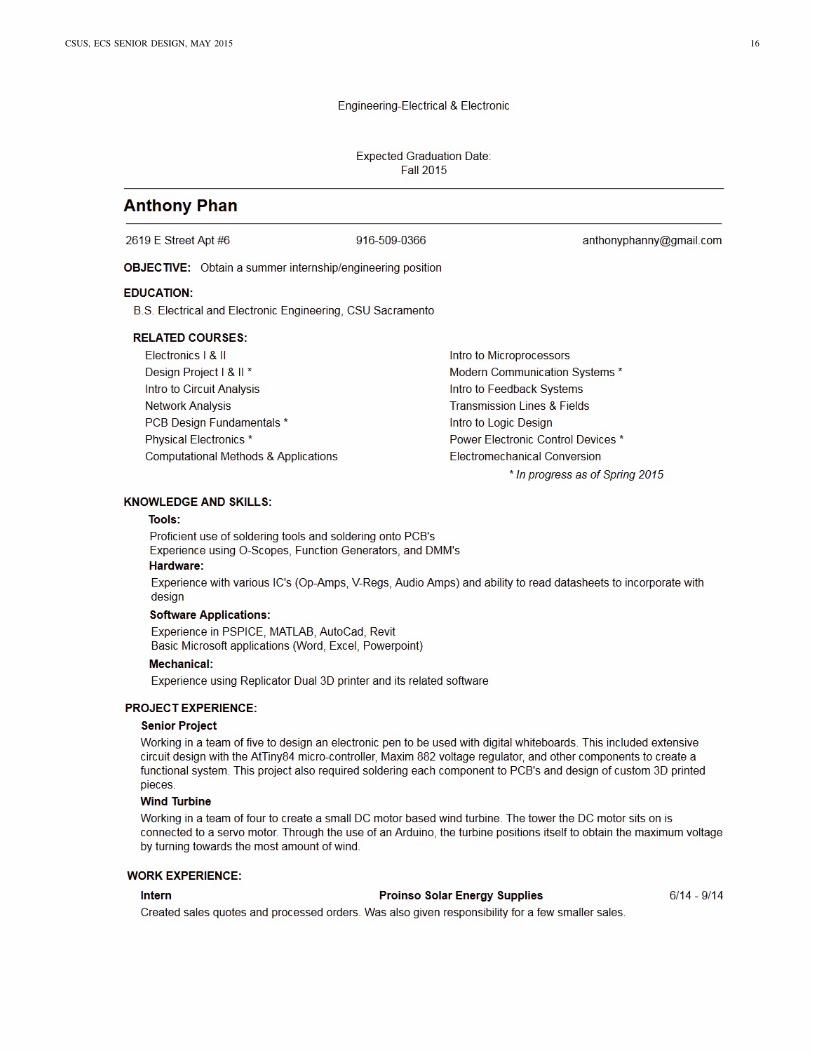
APPENDIX CTEAM MEMBER RESUMES

Jonathan Lloyd
OBJECTIVE Obtain a computer engineering position in embedded system development with possible leadership opportunities.
EDUCATIONB.S. DEGREE ▪ Computer Engineering ▪ California State University SacramentoA.A. DEGREE ▪ Social Science ▪ American River College, SacramentoA.A. DEGREE ▪ Language Studies ▪ American River College, Sacramento
Spring 201520142012
• Awarded Osher Scholars, and Fanselau Computer Science Scholarships.• Maintained a 3.59 GPA while taking upwards of 15 units per semester and working 20hrs per week.
PROJECTS AND ACTIVITIES• Wrote a robust C program utilizing multiprocessing and socket programming with a double pumping scheme.• Senior Design Project – Light pen for use with IR based digital whiteboards.
◦ Integrated 2.4GHz radio communication on a shared SPI bus with a USB interface and firmware.◦ Promoted a photon proximity sensor and developed a rapid prototype using its I2C interface.◦ Exemplified by instructors for engaging the audience during presentations.
• Designed a MIPS based RISC ASIC processor with a seven stage pipeline, and other advanced features.• Developed an OS in C/Assembly in a team of two in Linux using vi, gcc, make, gdb, Git, and Doxygen.
RELATED COURSES• Adv. Computer Organization• Computer Hardware Design• Computer Nwk and Internet• PCB Design Fundamentals
• Data Structures and Algorithms• DB Web Apps PHP/MySQL• Operating System Pragmatics• Obj Orient Prog in C++
• System Level Prog in C• Intermediate Network Tech • Group Communication• Small Business Mgmt
PROFESSIONAL EXPERIENCECOMPUTER/SOFTWARE ENGINEER 2013 – PresentEchelon Corp... San Jose, California; and Lumewave Inc. which was acquired by Echelon Corp.
• Selected to lead project to overhaul hardware and software implementation of the control management system.• Implemented and managed Git source control with a work flow adapted to accommodate the existing team needs.• Integrated a Google Maps Javascript API solution into VB.net based control management software to dynamically
display outdoor lighting control node geo-locations and detailed status information stored in a SQLite DB.• Wrote proof of concept message relay program in C which contributed to the migration to a Linux based solution.• Updated production firmware written in assembly to add functionality or accommodate hardware changes.• Took the lead in maintaining factory production software, providing support, and training international associates.• Trained technician to use a sophisticated voltage source, DMM, and custom equipment.• Significantly involved in engineering solutions to expand current product offering capabilities.• In-depth experience with SQLite optimization involving transaction queuing, and sophisticated queries.
AREA SUPERVISOR 2006 – 2008L.D.S Church... Caribbean Islands
• Promoted to Team Leader, then District Leader, supervising 4-6 area representatives.• Developed strong Spanish reading and writing skills with significant on-site experience including translation.
DATA CONTROLLER 2005 – 2006FDI Collateral Management (now known as Dealer Track)... Sacramento, California
• Designed a program in C# .NET and MS SQL to log process execution statistics on production servers.• Completed assignments ahead of schedule by programming scripts to automate tasks.
CUSTOMER SERVICE ASSOCIATE 2004 – 2005Sears Home Central... Sacramento, California
• Dramatically increased daily printing efficiency of over 300 service orders by programming scripts.
OTHER ACHIEVEMENTS AND EXPERIENCE• Attained the Eagle Scout award in the Boy Scouts of America program, and served in leadership positions.• Received an award for best leadership skills out of more than 20 participants in a leader training program.
CSUS, ECS SENIOR DESIGN, MAY 2015 14

CSUS, ECS SENIOR DESIGN, MAY 2015 15
CSUS, ECS SENIOR DESIGN, MAY 2015 16

CSUS, ECS SENIOR DESIGN, MAY 2015 17

CSUS, ECS SENIOR DESIGN, MAY 2015 18
ERIK R. METZNERerik.r.metzner [at] gmail {dot} com
Professional Objective:Obtain a position at a major computer systems engineering firm.Long-term: System architecture, artificial intelligence, OS development.
EDUCATIONComputer Engineering B.S. – CSU Sacramento – Senior, Graduating December 2015Physical Science/Mathematics A.S. – American River College – December 2011, GPA: 3.2
WORK EXPERIENCESoftware Engineering Intern, VeriFone, Rocklin, California. (May 2014 – August 2014)
• Designed an energy efficiency and software optimization project for portable point-of-sale terminals.• Collaborated with hardware engineers to resolve existing embedded OS bugs and hardware faults.
Architecture R&D Intern, Micron Technology, Folsom, California. (May 2012 – September 2013)• Created the HydraDrive system for SQA: Automated massive-multiboot server drive deployment.• Provided infrastructure support for automated Jenkins regression testing of the enterprise SSD product line.• Maintained and redeployed over one hundred SQA servers through multiple product expansions.
Engineering Contractor, Intel, Folsom, California. (2008)• Liaised with developers on graphics driver and firmware SQA for chipset-level graphics.• Conducted competitive graphics hardware performance analysis of nVidia & AMD product lines.
Owner, Performance Computing, Carmichael, California. (1999 – 2007)• Developed custom computer systems for professionals, with emphasis on OS performance optimization.• Applied OS-hardening, IO optimization, extensive overclocking, and custom cooling-system design.• Perfected OS-minimization: The extreme surgical reduction of bloated OS subsystems.
TECHNICAL EXPERIENCE Development: C, C++, Python, Perl, Bash, Verilog, VHDL, MATLAB, x86-assembly, Linux IPC,
debugging, concurrency, OO paradigms, source control, UML, the SDLC, Agile development, ADTs, CMOS layout, OpenSource RTOS, and JIRA / Confluence.
System Expertise: Linux & Windows optimization, hardware virtualization, Microsoft Sysprep, GRUB, SYSLINUX, MD-RAID, OS-minimization & hardening, and system stability testing.
Hardware Related: I2C, SPI, CAN, FPGAs & microcontrollers, PCB design & construction, electrical schematics, datasheets, thermal resistance, electronics packaging, soldering, battery chemistry / recharging, logic analyzers, oscilloscopes, DMMs, signal generators, extensive PC system-building & overclocking, custom PC cooling-system design. Familiar with (and own) over one thousand analog-glue and IC components from various manufacturers.
Limited 3D CAD, 3D Printing, NI LabVIEW, and MySQL experience.
Senior Project: Projector-based digital whiteboard. Hobby Projects: Pseudo A.I. personal assistant,24-core parallel processing microcontroller network, performance-optimized custom android ROM, Linux kernel minimization, software-defined radio, and homemade acrylic vacuum forming.
Other Notables: Nine years experience in Boy Scouts of America (Order of the Arrow). Lifelong experience with local community service. Five years experience in metalworking; lathe, machining, forging, casting, welding. Top 1% in state-wide mathematics and physical science testing as a youth.

CSUS, ECS SENIOR DESIGN, MAY 2015 19
Jonathan Lloyd Currently studying at CaliforniaState University Sacramento. J. Lloyd will completea B.S. in Computer Engineering in Spring 2015.While going to school J. Lloyd also works for Eche-lon. During J. Lloyds time with Echelon/Lumewavehe has been involved in the development of mi-crowave motion sensor, production test software forlighting control modules, commercial system man-agement software for lighting control modules, andother endeavors. In 2014 J. Lloyd was a key playerin modifying the lighting control module firmware
to accommodate new components that required changes in operational timing.
Jonathan Giacomelli I have been an avid computeruser since the age of three and have extensiveknowledge; from manually constructing basic cir-cuits all the way to high-level UI and UX design.I have successfully delivered high-quality enterprisesoftware, consisting of a polished UX/UI web-appfront-end and a secure industry compliant back-enddatabase. I have been frequently praised for my noveland rapidly deployed solutions to complex technicalproblems.
Anthony Phan I have good analytical skills as wellas being very hands on. Analog design has been myfavorite classes here at Sac State. Ive fixed up myguitar and bike a bunch of times, built my computerfrom scratch, and done basic home modifications. Ihave also been messing around with audio amplifiercircuits and would love to build my own qualityaudio amplifier.
Erik Metzner I am uniquely qualified for thisproject due to the fact that it was originally conceivedin a basic form at American River College, in thestudent engineering club ArcDev, with the oversightand design input of professor Tak Auyeung. I haveroughly a year and a half experience with the projectin the past and was the primary hardware designer inArcDev. Our senior design team was in a uniquelyprepared position to switch to this project mid-streamas Plan-B due to the fact that I already had themajority of the parts, had prototyped most of the
subsystems multiple times in the past, and contributed many hours to thisprojects research and development. The project was abandoned by the ArcDevclub after we lost too many members to university transfer. We spooledthis project up as a backup plan when we started noticing serious issuespiling up with the Wijit project and the people involved. Additionally, Ihave well over ten years experience constructing and optimizing computerhardware and software. I also began an avid electronics hobby when Iwas a child, breadboarding circuits from books by Forrest M. Mims IIIat RadioShack. I started soldering when I was ten and have since spenthundreds of hours on all of the popular IC manufacturers websites, orderingthousands of sample components, and spending more time than I would careto admit reading datasheets and dreaming up a slew of electronics projects.My main skills are in the computer domain though, in OS minimization andperformance optimization, system administration (Linux+Windows), C&C++/ Python / Perl programming, followed by OS hardening and computerhardware thermodynamics optimization; additionally I am fairly familiar withthe hardware of popular microcontrollers, common discrete offerings fromten major electronics companies, datasheets in general, parts procurement,component shopping aggregators, rapid prototyping, and other associatedinformation.
Jeff Moffet I am a good fit for our LightPen projectbecause I have done really well in my software andhardware classes that go towards my Computer En-gineering Degree. I also have 25 years of experienceworking with all types of computer related devices.Since I joined this team in the second semester,all of the other members already had their role inour project. Since I didnt want to intrude on whatanybody else was doing, I chose to take a back seatand just help out however I could. I wish I couldhave started at the beginning of our LightPen project,
because then I could have been more involved in the project. Taking everythinginto consideration, it worked out okay.