CSM J7KC J230-E1 2 1
26
1 Magnetic Contactor J7KC Series Best Match for upto 2.2 kW (240 VAC) *2 , 5.5 kW (440 VAC) Motor and Primary Side switches • Push-In Plus wiring Technology saves Wiring and Maintenance time • World's smallest size (*1) • Ideal for motor Control up to 2.2 kW (200 to 240 VAC) (*2), 5.5 kW (380 to 440 VAC), AC-3 class • Ideal for safety applications thanks to mirror contact mechanism with feedback function • High Contact Reliability (Min. 5 VDC, 3 mA) by Bifurcated contacts • Coil surge absorber unit installed as standard (*3) • Certified as compliant with the main safety standards *1. According to OMRON investigation, as of August 2019. For push-in models. *2. Based on JIS C 8201-4-1 *3. DC operated Model Number Structure Model Number Legend Order according to the format described in Ordering Information. J7KC@-12-@@ @@@@ (1) (2) (3) (4) For the most recent information on models that have been certified for safety standards, refer to your OMRON website. Refer to Safety Precautions on page 18. Operation Code Coil voltage DC-operated DC 12 12 VDC DC 24 24 VDC DC 48 48 VDC DC 60 60 VDC DC 100 100 VDC DC 110 110 VDC DC 120 120 VDC DC 200 200 VDC DC 210 210 VDC DC 220 220 VDC (1) Non-reversing/reversing (2) Frame size (3) Auxiliary contacts Code None Non-reversing R Reversing Code 12 12 A Code Contact form 10 SPST-1NO 01 SPST-1NC (4) Coil voltage Operation Code Coil voltage AC-operated AC 24 24 VAC AC 48 48 VAC AC 100 100 VAC AC 110 110 VAC AC 120 120 VAC AC 200 200 VAC AC 220 220 VAC AC 230 230 VAC AC 240 240 VAC AC 380 380 VAC AC 400 400 VAC AC 440 440 VAC AC 500 500 VAC
Transcript of CSM J7KC J230-E1 2 1

1
Magnetic Contactor
J7KC SeriesBest Match for upto 2.2 kW (240 VAC) *2, 5.5 kW (440 VAC) Motor and Primary Side switches• Push-In Plus wiring Technology saves Wiring and
Maintenance time• World's smallest size (*1)• Ideal for motor Control up to 2.2 kW (200 to 240 VAC) (*2),
5.5 kW (380 to 440 VAC), AC-3 class• Ideal for safety applications thanks to mirror contact
mechanism with feedback function• High Contact Reliability (Min. 5 VDC, 3 mA)
by Bifurcated contacts• Coil surge absorber unit installed as standard (*3)• Certified as compliant with the main safety standards
*1. According to OMRON investigation, as of August 2019. For push-in models.
*2. Based on JIS C 8201-4-1*3. DC operated
Model Number StructureModel Number Legend Order according to the format described in Ordering Information.
J7KC@-12-@@ @@@@(1) (2) (3) (4)
For the most recent information on models that have been certified for safety standards, refer to your OMRON website.
Refer to Safety Precautions on page 18.
Operation Code Coil voltage
DC-operated
DC 12 12 VDC
DC 24 24 VDC
DC 48 48 VDC
DC 60 60 VDC
DC 100 100 VDC
DC 110 110 VDC
DC 120 120 VDC
DC 200 200 VDC
DC 210 210 VDC
DC 220 220 VDC
(1) Non-reversing/reversing
(2) Frame size
(3) Auxiliary contacts
CodeNone Non-reversing
R Reversing
Code12 12 A
Code Contact form10 SPST-1NO
01 SPST-1NC
(4) Coil voltage
Operation Code Coil voltage
AC-operated
AC 24 24 VAC
AC 48 48 VAC
AC 100 100 VAC
AC 110 110 VAC
AC 120 120 VAC
AC 200 200 VAC
AC 220 220 VAC
AC 230 230 VAC
AC 240 240 VAC
AC 380 380 VAC
AC 400 400 VAC
AC 440 440 VAC
AC 500 500 VAC
J7KC Series
2
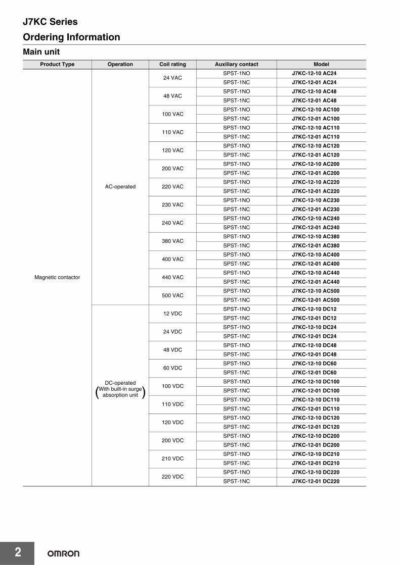
Ordering InformationMain unit
Product Type Operation Coil rating Auxiliary contact Model
Magnetic contactor
AC-operated
24 VACSPST-1NO J7KC-12-10 AC24
SPST-1NC J7KC-12-01 AC24
48 VACSPST-1NO J7KC-12-10 AC48
SPST-1NC J7KC-12-01 AC48
100 VACSPST-1NO J7KC-12-10 AC100
SPST-1NC J7KC-12-01 AC100
110 VACSPST-1NO J7KC-12-10 AC110
SPST-1NC J7KC-12-01 AC110
120 VACSPST-1NO J7KC-12-10 AC120
SPST-1NC J7KC-12-01 AC120
200 VACSPST-1NO J7KC-12-10 AC200
SPST-1NC J7KC-12-01 AC200
220 VACSPST-1NO J7KC-12-10 AC220
SPST-1NC J7KC-12-01 AC220
230 VACSPST-1NO J7KC-12-10 AC230
SPST-1NC J7KC-12-01 AC230
240 VACSPST-1NO J7KC-12-10 AC240
SPST-1NC J7KC-12-01 AC240
380 VACSPST-1NO J7KC-12-10 AC380
SPST-1NC J7KC-12-01 AC380
400 VACSPST-1NO J7KC-12-10 AC400
SPST-1NC J7KC-12-01 AC400
440 VACSPST-1NO J7KC-12-10 AC440
SPST-1NC J7KC-12-01 AC440
500 VACSPST-1NO J7KC-12-10 AC500
SPST-1NC J7KC-12-01 AC500
DC-operatedWith built-in surge
absorption unit
12 VDCSPST-1NO J7KC-12-10 DC12
SPST-1NC J7KC-12-01 DC12
24 VDCSPST-1NO J7KC-12-10 DC24
SPST-1NC J7KC-12-01 DC24
48 VDCSPST-1NO J7KC-12-10 DC48
SPST-1NC J7KC-12-01 DC48
60 VDCSPST-1NO J7KC-12-10 DC60
SPST-1NC J7KC-12-01 DC60
100 VDCSPST-1NO J7KC-12-10 DC100
SPST-1NC J7KC-12-01 DC100
110 VDCSPST-1NO J7KC-12-10 DC110
SPST-1NC J7KC-12-01 DC110
120 VDCSPST-1NO J7KC-12-10 DC120
SPST-1NC J7KC-12-01 DC120
200 VDCSPST-1NO J7KC-12-10 DC200
SPST-1NC J7KC-12-01 DC200
210 VDCSPST-1NO J7KC-12-10 DC210
SPST-1NC J7KC-12-01 DC210
220 VDCSPST-1NO J7KC-12-10 DC220
SPST-1NC J7KC-12-01 DC220
( )
J7KC Series
3
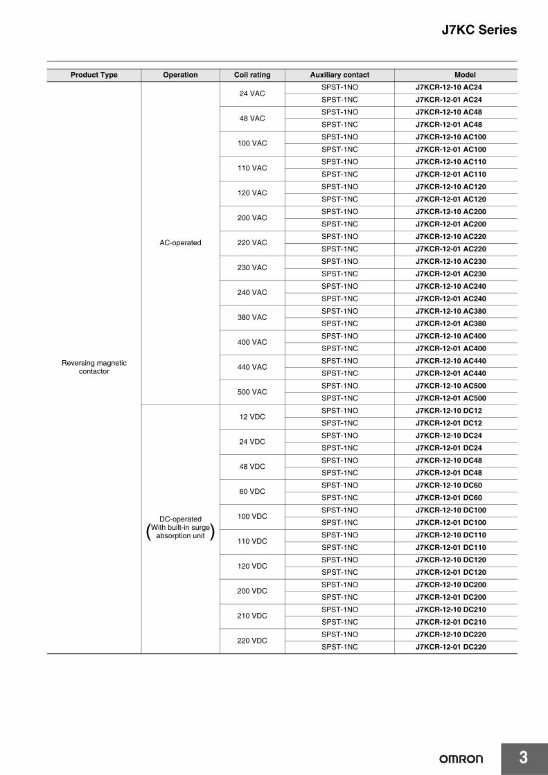
Product Type Operation Coil rating Auxiliary contact Model
Reversing magnetic contactor
AC-operated
24 VACSPST-1NO J7KCR-12-10 AC24
SPST-1NC J7KCR-12-01 AC24
48 VACSPST-1NO J7KCR-12-10 AC48
SPST-1NC J7KCR-12-01 AC48
100 VACSPST-1NO J7KCR-12-10 AC100
SPST-1NC J7KCR-12-01 AC100
110 VACSPST-1NO J7KCR-12-10 AC110
SPST-1NC J7KCR-12-01 AC110
120 VACSPST-1NO J7KCR-12-10 AC120
SPST-1NC J7KCR-12-01 AC120
200 VACSPST-1NO J7KCR-12-10 AC200
SPST-1NC J7KCR-12-01 AC200
220 VACSPST-1NO J7KCR-12-10 AC220
SPST-1NC J7KCR-12-01 AC220
230 VACSPST-1NO J7KCR-12-10 AC230
SPST-1NC J7KCR-12-01 AC230
240 VACSPST-1NO J7KCR-12-10 AC240
SPST-1NC J7KCR-12-01 AC240
380 VACSPST-1NO J7KCR-12-10 AC380
SPST-1NC J7KCR-12-01 AC380
400 VACSPST-1NO J7KCR-12-10 AC400
SPST-1NC J7KCR-12-01 AC400
440 VACSPST-1NO J7KCR-12-10 AC440
SPST-1NC J7KCR-12-01 AC440
500 VACSPST-1NO J7KCR-12-10 AC500
SPST-1NC J7KCR-12-01 AC500
DC-operatedWith built-in surge
absorption unit
12 VDCSPST-1NO J7KCR-12-10 DC12
SPST-1NC J7KCR-12-01 DC12
24 VDCSPST-1NO J7KCR-12-10 DC24
SPST-1NC J7KCR-12-01 DC24
48 VDCSPST-1NO J7KCR-12-10 DC48
SPST-1NC J7KCR-12-01 DC48
60 VDCSPST-1NO J7KCR-12-10 DC60
SPST-1NC J7KCR-12-01 DC60
100 VDCSPST-1NO J7KCR-12-10 DC100
SPST-1NC J7KCR-12-01 DC100
110 VDCSPST-1NO J7KCR-12-10 DC110
SPST-1NC J7KCR-12-01 DC110
120 VDCSPST-1NO J7KCR-12-10 DC120
SPST-1NC J7KCR-12-01 DC120
200 VDCSPST-1NO J7KCR-12-10 DC200
SPST-1NC J7KCR-12-01 DC200
210 VDCSPST-1NO J7KCR-12-10 DC210
SPST-1NC J7KCR-12-01 DC210
220 VDCSPST-1NO J7KCR-12-10 DC220
SPST-1NC J7KCR-12-01 DC220
( )

J7KC Series
4
Options (Order Separately)Auxiliary contact unit
Interlock unit
Reversing conductor kit
Coil surge absorption unit
Insulation stop
Tools for removal
Number of poles Auxiliary contact Model
2 poles
2PST-2NO J73KC-AM-20
2PST-1NO 1NC J73KC-AM-11
2PST-2NC J73KC-AM-02
4 poles
4PST-4NO J73KC-AM-40
4PST-3NO 1NC J73KC-AM-31
4PST-2NO 2NC J73KC-AM-22
4PST-1NO 3NC J73KC-AM-13
4PST-4NC J73KC-AM-04
Model
J74KC-A
Type Model
For main circuit J75KC-WKR-A
For auxiliary circuit J75KC-WKR-B
Adopted Coil voltage type LED indicator Model
24-48 VAC
No
J76KC-RC-1
48-125 VAC J76KC-RC-2
100-250 VAC J76KC-RC-3
24-48 VACYes
J76KC-RC-N-1
48-125 VAC J76KC-RC-N-2
Model Minimum order (bag)
J77KC-K 1(30 pcs./bag)
Model
J78KC

J7KC Series
5
Ratings/SpecificationsThe ratings/specifications are the same for both non-reversing/reversing types.
Coil ratingAC operated
DC operated
Coil characteristics (reference value)AC operated
Note: 1. Coil ratings: Characteristics for 200 VAC, 50 Hz / 200-220 VAC, 60 Hz2. Coil power consumption value is the same for a coil that is not rated 200 VAC.3. Indicated operate/release times for 200 VAC, 50 Hz.4. Closed and open voltages of 100 V coil (100 VAC, 50 Hz/100-110 VAC, 60 Hz) are approximately one half the values in the table above.5. Values in the table above are examples for 20°C cold condition.
DC operated
Note: 1. Coil ratings: Characteristics for 24 VDC2. Coil power consumption value is the same for a coil that is not rated 24 VDC.3. Values in the table above are examples for 20°C cold condition.
Displayed model
Rated voltage Allowable voltage range Must operate voltage
Must release voltage50 Hz 60 Hz 50 Hz 60 Hz
AC 24 24 VAC 24-26 VAC
85 to 110%
21-27 VAC 21-29 VAC
85% max. 20% min.
AC 48 48 VAC 48-52 VAC 41-53 VAC 41-58 VACAC 100 100 VAC 100-110 VAC 85-110 VAC 85-121 VACAC 110 100-110 VAC 110-120 VAC 85-121 VAC 94-132 VACAC 120 110-120 VAC 120-130 VAC 94-132 VAC 102-143 VACAC 200 200 VAC 200-220 VAC 170-220 VAC 170-242 VACAC 220 200-220 VAC 220-240 VAC 170-242 VAC 187-264 VACAC 230 220-230 VAC 230 VAC 187-253 VAC 196-253 VACAC 240 220-240 VAC 240-260 VAC 187-264 VAC 204-286 VACAC 380 346-380 VAC 380-420 VAC 295-418 VAC 323-462 VACAC 400 380-400 VAC 400-440 VAC 323-440 VAC 340-484 VACAC 440 415-440 VAC 440-480 VAC 353-484 VAC 374-528 VACAC 500 480-500 VAC 500-550 VAC 408-550 VAC 425-605 VAC
Displayed model Rated voltage Allowable voltage range Must operate
voltageMust release
voltageDC 12 12 VDC
85 to 110%
11-14 VDC
85% max. 10% min.
DC 24 24 VDC 21-27 VDCDC 48 48 VDC 41-53 VDCDC 60 60 VDC 51-66 VDCDC 100 100 VDC 85-110 VDCDC 110 110 VDC 94-121 VDCDC 120 120 VDC 102-132 VDCDC 200 200 VDC 170-220 VDCDC 210 210 VDC 179-231 VDCDC 220 220 VDC 187-242 VDC
Frequency 50 Hz 60 Hz
Coil power consumption
Making (VA) 22 (200 V) 25 (220 V)Holding (VA) 4.5 (200 V) 4.5 (220 V)
Power loss (W) 1.2 (200 V) 1.3 (220 V)Must operate voltage (V) 122 to 135 128 to 138Must release voltage (V) 80 to 89 83 to 96Operate time (ms) 17 to 26Release time (ms) 6 to 16
Coil power consumption
Making (W) 2.4 (24 V)Holding (W) 2.2 (24 V)
Time constant (ms) Holding 20Must operate voltage (V) 10 to 11Must release voltage (V) 4 to 6Operate time (ms) 34 to 60Release time (ms) 5 to 10

J7KC Series
6
Ratings/Characteristics
* The electrical endurance is the value at 200 V based on the electrical endurance test conditions assumed in the IEC/JIS standards, and will vary depending on the characteristics and load conditions of the motor you use. A large motor starting current may cause a decrease of electrical endurance or contact sticking.
Main circuit rating
Rating based on IEC 60947-4-1
AC-1(Resistive load)
Voltage range (V) AC200-240 AC AC380-440 AC
Rated operational current (A) 15 15
AC-3(3-phase cage motor)
Voltage range (V) 200-240 AC 380-440 AC 500-550 AC 600-690 AC
Rated capacity (kW) 3 5.5 5.5 4
Rated operational current (A) 12 12 9 5
AC-4(3-phase cage motor)
Voltage range (V) 200-240 AC 380-440 AC 500-550 AC 600-690 AC
Rated capacity (kW) 3 5.5 5.5 4
Rated operational current (A) 12 12 9 5
DC-1(Resistive loadL/R ≤ 1 ms)
Voltage range (V) 24 DC 48 DC 110 DC 220 DC
Rated operational current (A)
Number of serial contacts 1 12 12 3 0.7
Number of serial contacts 2 12 12 9 4
Number of serial contacts 3 12 12 12 12
DC-3, DC-5(DC motor loadL/R ≤ 15 ms)
Voltage range (V) 24 DC 48 DC 110 DC 220 DC
Rated operational current (A)
Number of serial contacts 1 2 1.5 1 0.1
Number of serial contacts 2 10 3 0.85 0.35
Number of serial contacts 3 12 6 1.7 0.7
Conventional free air thermal current (rated flowing current) (A) 15
Rating based on UL 60947-4-1, CSA C22.2
3-phase motor
Voltage range (V) 200 AC 220-240 AC 440-480 AC 550-600 AC
Rated capacity (HP) 3 3 5 5
Rated operational current (A) 11 9.6 7.6 6.1
Rated current (A) 15
Single-phase motor
Voltage range (V) 110-120 AC 200 AC 220-240 AC
Rated capacity (HP) 3/4 1-1/2 2
Rated operational current (A) 13.8 11.5 12
Rated current (A) 15
FUSE 30A (Class K5, RK5)
Rating based on JIS C 8201-4-1
AC-1 (resistive load)
Voltage range (V) 200-240 AC 380-440 AC
Rated operational current (A) 15 15
AC-3(3-phase cage motor)
Voltage range (V) 200-240 AC 380-440 AC 500-550 AC
Rated capacity (kW) 2.2 5.5 5.5
Rated operational current (A) 12 12 9
DC-1(Resistive loadL/R ≤ 1 ms)
Voltage range (V) 24 DC 48 DC 110 DC 220 DC
Rated operational current (A)
Number of serial contacts 1 12 12 3 0.7
Number of serial contacts 2 12 12 9 4
Number of serial contacts 3 12 12 12 12
DC-3, DC-5(DC motor loadL/R ≤ 15 ms)
Voltage range (V) 24 DC 48 DC 110 DC 220 DC
Rated operational current (A)
Number of serial contacts 1 2 1.5 1 0.1
Number of serial contacts 2 10 3 0.85 0.35
Number of serial contacts 3 12 6 1.7 0.7
Conventional free air thermal current (rated flowing current) (A) 15
Minimum operate voltage/current (reference value) 24 VDC 10 mA
Electrical/mechanical endurance
Voltage range (V) 220 AC 440 AC
Rated operational current (A) 12 12
Contact closed current (A) 144 144
Breaking current (A) 120 120
Switching frequency (times per hour) 1800 1800
Endurance(10,000 operations min.)
Mechanical 1000 1000
Electrical (AC3) 100 *
Contact resistance (reference value) 10 mΩ max. (6 VDC, 1 mA, voltage drop method)
J7KC Series
7
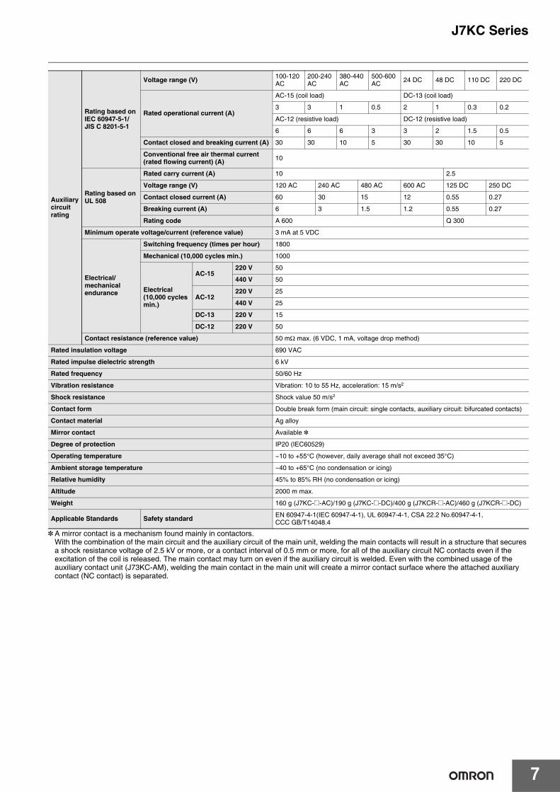
* A mirror contact is a mechanism found mainly in contactors.With the combination of the main circuit and the auxiliary circuit of the main unit, welding the main contacts will result in a structure that secures a shock resistance voltage of 2.5 kV or more, or a contact interval of 0.5 mm or more, for all of the auxiliary circuit NC contacts even if the excitation of the coil is released. The main contact may turn on even if the auxiliary circuit is welded. Even with the combined usage of the auxiliary contact unit (J73KC-AM), welding the main contact in the main unit will create a mirror contact surface where the attached auxiliary contact (NC contact) is separated.
Auxiliarycircuit rating
Rating based on IEC 60947-5-1/JIS C 8201-5-1
Voltage range (V) 100-120 AC
200-240 AC
380-440 AC
500-600 AC 24 DC 48 DC 110 DC 220 DC
Rated operational current (A)
AC-15 (coil load) DC-13 (coil load)
3 3 1 0.5 2 1 0.3 0.2
AC-12 (resistive load) DC-12 (resistive load)
6 6 6 3 3 2 1.5 0.5
Contact closed and breaking current (A) 30 30 10 5 30 30 10 5
Conventional free air thermal current(rated flowing current) (A) 10
Rating based on UL 508
Rated carry current (A) 10 2.5
Voltage range (V) 120 AC 240 AC 480 AC 600 AC 125 DC 250 DC
Contact closed current (A) 60 30 15 12 0.55 0.27
Breaking current (A) 6 3 1.5 1.2 0.55 0.27
Rating code A 600 Q 300
Minimum operate voltage/current (reference value) 3 mA at 5 VDC
Electrical/mechanical endurance
Switching frequency (times per hour) 1800
Mechanical (10,000 cycles min.) 1000
Electrical (10,000 cycles min.)
AC-15220 V 50
440 V 50
AC-12220 V 25
440 V 25
DC-13 220 V 15
DC-12 220 V 50
Contact resistance (reference value) 50 mΩ max. (6 VDC, 1 mA, voltage drop method)
Rated insulation voltage 690 VAC
Rated impulse dielectric strength 6 kV
Rated frequency 50/60 Hz
Vibration resistance Vibration: 10 to 55 Hz, acceleration: 15 m/s2
Shock resistance Shock value 50 m/s2
Contact form Double break form (main circuit: single contacts, auxiliary circuit: bifurcated contacts)
Contact material Ag alloy
Mirror contact Available *
Degree of protection IP20 (IEC60529)
Operating temperature −10 to +55°C (however, daily average shall not exceed 35°C)
Ambient storage temperature −40 to +65°C (no condensation or icing)
Relative humidity 45% to 85% RH (no condensation or icing)
Altitude 2000 m max.
Weight 160 g (J7KC-@-AC)/190 g (J7KC-@-DC)/400 g (J7KCR-@-AC)/460 g (J7KCR-@-DC)
Applicable Standards Safety standard EN 60947-4-1(IEC 60947-4-1), UL 60947-4-1, CSA 22.2 No.60947-4-1,CCC GB/T14048.4

J7KC Series
8
Engineering DataElectrical endurance curvesAC-3 breaking current and electrical endurance curve (Based on IEC 60947-4-1)
AC-1 breaking current and electrical endurance curve (for resistive load) (Based on IEC 60947-4-1)
Breaking current [A]
Ele
ctric
al e
ndur
ance
[10,
000
cycl
es]
1
10
100
1000
1
10
100
1000
1
10
100
1000
1
10
100
1000
0001001011
380-440V 50/60Hz
500-550V 50/60Hz
3kW
2.2k
W
1.5k
W
5.5k
W
5.5k
W
600-690V 50/60Hz 4kW
2.2k
W
200 to 240V
380 to 440V
500 to 550V
600 to 690V
3kW
3kW
Sta
ndar
d m
otor
ra
ted
capa
city
/cur
rent
200-240 V 50/60 Hz
1 10 100 1000
200-240 V
380-440 V
15 A
200-240 V 50/60 Hz
380-440 V 50/60 Hz
1
10
2
3
5
100
20
30
50
1000
200
300
500
1
10
2
3
5
100
20
30
50
1000
200
300
500
Breaking current [A]
Ele
ctric
al e
ndur
ance
[10,
000
cycl
es]

J7KC Series
9
Dimensions (Unit: mm)
*1. When auxiliary contact unit (J73KC) is mounted
*2. For DC-operated model
L11 3 L2 5 L3 13 NO A1 +
-A214T3T2 62 T1 4
22
21 5/L3 3/L2
4/T2 6/T3 2/T1
1/L1
A1 (+)
A2 (-)
(1b)1NC
(1a)1NO
Contact formAuxiliary contact
6/T3 4/T2 2/T1
1/L1 3/L2 5/L3 13
14
A2 (-)
A1 (+)
*2
*2
*2
*2
*2
*2
3
8.7
*2
*2
Auxiliary terminals Coil terminalsMain terminals
Auxiliary terminalsMain terminals Coil terminals
45 46
67.5 52
(41.5) *1
62 (for 16 rail mounting height)
Main unitMagnetic contactorJ7KC
2/T1 4/T2 6/T3
5/L3 3/L2 1/L1
2/T1 4/T2 6/T3 14
13 5/L3 3/L2 1/L1 13
14
1 NO x 2
Apply a separate electrical interlock.
1 NC x 2
22
21 1/L1 3/L2 5/L3 21
226/T34/T22/T1
1/L1 3/L2 5/L3
6/T34/T22/T1
(+)A1
A2(-)
*2
*2
*2
*2
*2
(+)A1
A2(-)
A2(-)
A2(-)
(+)A1
(+)A1
Connection diagram
*2
*2
*2
*2
*1. When auxiliary contact unit (J73KC) is mounted
*2. For DC-operated model
Note:
*2
38.7
The terminal (number) names of the reversing magnetic contactor are the same as the magnetic contactor.
45.5
90.5
53
75
52 67.5
88 (for 16 rail mounting height)
Approx. 5
Approx. 5
(41.5) *1
Reversing magnetic contactorJ7KCR

J7KC Series
10
Related Products (Order Separately)Thermal overload relayJ7TCCombine with a thermal overload relay to use as a magnetic switch.For details, refer to J7TC Thermal Overload Relay Data Sheet (Catalog No. J231-E1).
+ =
J7KC J7TCMagnetic starters
L11 3 L2 5 L3 13 NO A1 +
A214T3T2 62 T1 4 -
555.5
Reset rod
Operation indicator window
38.8
7.6
67.552
8.7
45
114
40.5
80
137
463
1NC(1b) 969522
1/L1 3/L2 5/L3 21
98 97 6/T3 4/T2 2/T1
1NO(1a)
1/L1 3/L2 5/L3 13
14 95 96
98 97 6/T3 4/T2 2/T1
*2A2(-)
A1(+)*2
*2
*2
*2
A2(-)
*2A1(+)
2 T1 4 T2 6 T3
62 (for 16 rail mounting height)
(41.5) *1
Auxiliary terminals
Auxiliary terminals
Auxiliary terminals
Coil terminals
Auxiliary contact Connection diagram
Main terminals
Main terminals
NONC
9895
9796
*1 When auxiliary contact unit (J73KC) is mounted*2 For DC-operated model
App
rox.
5
75
3 555.5
3 53
52
8.8
40.5
114
80
67.5
137
8.745.5
90.5
Operation indicator window
Main terminals
Reset button
6 T34 T22 T1
6T34T22T1 A2
A1135L3
6T34T2
3L21L1
2T1A214
A1135L33L21L1
Auxiliary terminals
Reset button
88 (for 16 rail mounting height)
(41.5) *1
NONC
9895
9796
1 NO x 2
Apply a separate electrical interlock.
1 NC x 2
2/T1
4/T2
6/T3
5/ L3
3/ L2
1/L1
2/T1 4/T2
6/T3 14
13 5/L3
3/L2
1/L1 13
14
6/T34/T22/T19798
95 96
(+)A1
A2(-)*2
*2 (+)*2A1
A2(-)*2
*2
*2
22
21 1/L1 3/L2
5/L3
21
226/T3
4/T2
2/T1
1/L1
3/L2
5/L3
6/T3
4/T2
2/T1
98 972/T1 4/T2 6/T3
95 96
A2(-)*2
*2
*2
A2(-)
(+)A1
(+)*2A1
Connection diagram
Magnetic starters
Reversing type magnetic starters

J7KC Series
11
Coordination with the short circuit protection device (SCPD) (based on IEC and JIS standards)Assumed short circuit current "r" (240 V, 440 V)
Conditional rated short circuit current Iq (240 V)
Magnetic starters Coordination type
Magnetic contactor
Thermal overload relay Type 1 Type 2
Setting current range
[A]
Short-circuit current ”r”
[kA]
BreakerEN60947-2
Rating[A]
Short-circuit current ”r”
[kA]
Fuse rating [A](IEC 60269-1 gG and gM)
J7KC-12 J7TC-01
0.34-0.52
1
Breaker for wiring protection(MCCB)Icu240 V 5 kA440 V 2.5 kA
3
1
2
0.48-0.72
40.64-0.965
0.8-1.2
0.95-1.4510
16
1.1-1.65
1.4-2.1
20
1.7-2.6
2.2-3.4
2.8-4.2
4-6
5-7.5
6-9
7-10.5
9-13 30
Magnetic starters Coordination type
Magnetic contactor
Thermal overload relay Type 1 Type 2
Setting current range
[A]
Short-circuit current ”Iq”
[kA]
BreakerEN60947-2
Rating[A]
Short-circuit current ”Iq”
[kA]
Fuse rating [A](IEC 60269-1 gG and gM)
J7KC-12 J7TC-01
0.34-0.52
25
Breaker for wiring protection(MCCB)Icu240 V 5 kA440 V 2.5 kA
3
50
2
0.48-0.72
40.64-0.965
0.8-1.2
0.95-1.45
10
161.1-1.65
1.4-2.1
20
1.7-2.6
2.2-3.4
2.8-4.2
4-6
5-7.5 Breaker for wiring protection(MCCB)Icu240 V 50 kA440 V 30 kA
306-9
7-10.5
9-13

J7KC Series
12
Manual motor starterJ7MCFor details, refer to J7MC Manual Motor Starter Data Sheet (Catalog No.J233-E1).
Short-circuit harmonized protectionSatisfies the harmonized protection types 1 and 2 for magnetic switches and short-circuit protection devices specified in IEC 60947 and JIS C 8201.• Type 1: Damage to magnetic contactors and thermal overload relays is observed. Requires partial or complete replacement at the time of
inspection.• Type 2: No damage, except slight welding of the contacts in the magnetic contactor. Can remain in use without replacement at the time of
inspection.This greatly reduces the possibility of secondary accidents in the event that an accident occurs.
Type 1 rated conditional short-circuit current Iq = 50 kA (200 VAC, 400 VAC)
Note: The 3-phase motor full load current is a reference value. When applying, check the full load current of the motor you will use.
Type 2 rated conditional short-circuit current Iq = 50 kA (200 VAC, 400 VAC)
Note: The 3-phase motor full load current is a reference value. When applying, check the full load current of the motor you will use.
3-phase motor capacity and full load currentManual motor starter Short-circuit
currentIq
[kA]
Magnetic contactor200 VAC 400 VAC
Capacity [kW]
Current [A]
Capacity [kW]
Current [A] Model Current setting
range [A] ModelRated operational
currentAC-3 [A]
J7MC-3P-E16 J7MC-3R-E16 0.1-0.16
50 J7KC-12 12
0.03 0.24 0.06 0.23 J7MC-3P-E25 J7MC-3R-E25 0.16-0.25
0.06 0.37 0.09 0.32 J7MC-3P-E4 J7MC-3R-E4 0.25-0.4
0.12 0.5 J7MC-3P-E63 J7MC-3R-E63 0.4-0.63
0.1 0.68 0.18 0.65 J7MC-3P-1 J7MC-3R-1 0.63-1.0
0.25 0.9 J7MC-3P-1 J7MC-3R-1 0.63-1.0
0.2 1.3 0.37 1.25 J7MC-3P-1E6 J7MC-3R-1E6 1.0-1.6
0.55 1.6 J7MC-3P-2E5 J7MC-3R-2E5 1.6-2.5
0.4 2.3 0.75 2 J7MC-3P-2E5 J7MC-3R-2E5 1.6-2.5
1.1 2.5 J7MC-3P-4 J7MC-3R-4 2.5-4.0
0.75 3.6 1.5 3.5 J7MC-3P-4 J7MC-3R-4 2.5-4.0
1.5 6.1 2.2 5 J7MC-3P-6 J7MC-3R-6 4.0-6.3
3-phase motor capacity and full load currentManual motor starter Short-circuit
currentIq
[kA]
Magnetic contactor200 VAC 400 VAC
Capacity [kW]
Current [A]
Capacity [kW]
Current [A] Model Current setting
range [A] ModelRated operational
currentAC-3 [A]
J7MC-3P-E16 J7MC-3R-E16 0.1-0.16
50 J7KC-12 12
0.03 0.24 0.06 0.23 J7MC-3P-E25 J7MC-3R-E25 0.16-0.25
0.06 0.37 0.09 0.32 J7MC-3P-E4 J7MC-3R-E4 0.25-0.4
0.12 0.5 J7MC-3P-E63 J7MC-3R-E63 0.4-0.63
0.1 0.68 0.18 0.65 J7MC-3P-1 J7MC-3R-1 0.63-1.0
0.25 0.9 J7MC-3P-1 J7MC-3R-1 0.63-1.0
0.2 1.3 0.37 1.25 J7MC-3P-1E6 J7MC-3R-1E6 1.0-1.6
0.55 1.6 J7MC-3P-2E5 J7MC-3R-2E5 1.6-2.5
0.4 2.3 0.75 2 J7MC-3P-2E5 J7MC-3R-2E5 1.6-2.5
1.1 2.5 J7MC-3P-4 J7MC-3R-4 2.5-4.0
0.75 3.6 1.5 3.5 J7MC-3P-4 J7MC-3R-4 2.5-4.0

J7KC Series
13
Rated combination table and SCCR for North America
* An area where horsepower is not defined in UL60947-4-1 (SCCR is acquired in this area)
220-240 V 440-480 V Manual motor starter Magnetic contactor Short-circuit
current ratingSCCR[kA]
Rated capacity
[Hp]
Rated operational current [A]
Rated capacity
[Hp]
Rated operational current [A]
Model Current setting range [A] Model
*
0.16
*
0.16 J7MC-3P-E16 J7MC-3R-E16 0.1-0.16
J7KC-12
65 kA
0.25 0.25 J7MC-3P-E25 J7MC-3R-E25 0.16-0.25 65 kA
0.4 0.4 J7MC-3P-E4 J7MC-3R-E4 0.25-0.4 65 kA
0.63 0.63 J7MC-3P-E63 J7MC-3R-E63 0.4-0.63 65 kA
1 1 J7MC-3P-1 J7MC-3R-1 0.63-1.0 65 kA
1.6 3/4 1.6 J7MC-3P-1E6 J7MC-3R-1E6 1.0-1.6 65 kA
1/2 2.2 1 2.1 J7MC-3P-2E5 J7MC-3R-2E5 1.6-2.5 65 kA
3/4 3.2 2 3.4 J7MC-3P-4 J7MC-3R-4 2.5-4 65 kA
1-1/2 6 3 4.8 J7MC-3P-6 J7MC-3R-6 4-6.3 65 kA
5 7.6 J7MC-3P-10 J7MC-3R-10 6.3-10 25 kA
3 9.6 J7MC-3P-10 J7MC-3R-10 6.3-10 25 kA
7-1/2 11 J7MC-3P-13 J7MC-3R-13 9-13 10 kA

J7KC Series
14
Options (Order Separately)
Auxiliary contact unitJ73KC Ratings
Connection diagram
Dimensions
Conventional free air thermal
current (rated flowing
current)[A]
Contact closed andBreaking current
[A]
AC DC
Minimum operatevoltage/current
Operating voltage
[V]
Rated operational current (A) Operating
voltage[V]
Rated operational current (A)
Coil load(AC-15)
Resistive load
(AC-12)
Coil load (DC-13)
Resistive load
(DC-12)
10
30 100 to 120 AC 3 6 24 DC 2 3
5 VDC, 3 mA
30 200 to 240 AC 3 6 48 DC 1 2
10 380 to 440 AC 1 6 110 DC 0.3 1.5
5 500 to 600 AC 0.5 3 220 DC 0.2 0.5
Model Contact configuration
J73KC-AM-40 4PST-4NO(4NO)
J73KC-AM-31 4PST-3NO 1NC(3NO1NC)
J73KC-AM-22 4PST-2NO 2NC(2NO2NC)
J73KC-AM-13 4PST-1NO 3NC(1NO3NC)
53 63 73 83
54 64 74 84
53 61 73 83
54 62 74 84
53 61 71 83
54 62 72 84
53 61 71 81
54 62 72 82
Model Contact configuration
J73KC-AM-04 4PST-4NC(4NC)
J73KC-AM-20 2PST-2NO(2NO)
J73KC-AM-11 2PST-1NO 1NC(1NO1NC)
J73KC-AM-02 2PST-2NC(2NC)
51 61 71 81
52 62 72 82
53
54
63
64
53
54
61
62
51
52
61
62
8.78.7
3 41.538.5
40.526.5
6
7
22
83.8
Interlock unitJ74KC

J7KC Series
15
54.2
36.845.5
Approx. 58.2Approx. 49.5
62.9
45.5
28.1
62.9
45.528.1
Approx. 66.9Approx. 66.9
1 3 5
2 4 6
1 3 5
2 4 6
2/T1
1/L1
22
21 3/L2 5/L3 21
226/T34/T2
1/L1 3/L2 5/L3
6/T34/T22/T1 A2A2
A1 A1
Reversing conductor kitJ75KC-WKR-A
For power supply side For load side
For power supply side For load side
J75KC-WKR-B
Coil surge absorption unitRatings
* The DC operated (J7KC-@-DC) has a varistor built into the main unit.
Dimensions
Model Surge absorber
Varistor voltage
LED indicator
Applicable model Control circuit voltage
AC operated DC operated AC DC
J76KC-RC-1
Varistor
100 V
---
J7KC-@-AC ---
24-48 VAC
Not required
*
J76KC-RC-2 240 V 48-125 VAC
J76KC-RC-3 470 V 100-250 VAC
J76KC-RC-N-1 100 VLED (red)
24-48 VAC
J76KC-RC-N-2 240 V 48-125 VAC
Internal connection diagram
15
35 6.5
23
LED (Red)
23
6.5
26.5
46.5
Internal connection diagram
J76KC-RC-N
J76KC-RC

J7KC Series
16
1
1
8.5
7
7
16.7
16.7
8.5
J77KC-K
Insulation stopJ77KC-K Guide for insertion into terminal (insertion) holes to stabilize holding of 1mm2 or less stranded wire (direct insertion).
137
20
14.5
Tools for removalJ78KC

J7KC Series
17
DIN Rails (Order Separately) (Unit: mm)
Note: 1. Order the parts above in units of ten. The prices shown above are standard prices for one piece.2. Rails conform to DIN standards.
4.5
15 25 2510 10
1,000 (500) *25 25 15 (5) *
35±0.3
7.3±0.15
27±0.15
1
* ( ) indicates the dimensions of the PFP-50N.
Mounting RailPFP-100NPFP-50N
Model
PFP-100N
PFP-50N
4.5
15 25 2510 10
1,000
25 25 15 1 1.5
29.2242735±0.3
16
Mounting RailPFP-100N2
Model
PFP-100N2
1.3
4.8
35.5 35.51.8
1.8
M4 springwasher
106.2
150
M4×8pan-head
screw
11.5
10
End PlatePFP-M
Model
PFP-M
516
12
44.334.8
16.5
SpacerPFP-S
Model
PFP-S

J7KC Series
18
Safety PrecautionsWarning Indications
Meaning of Product Safety Symbols
Do not touch or approach the product while or immediately after power is supplied. Electric shock or burn injuries may occur.
Never disassemble, modify, or repair the product ortouch any of the internal parts. Minor electric shock, fire, or malfunction mayoccasionally occur.
Do not use the product in an environment where flammable or explosive gas is present.
Relay life expectancy varies considerably with output load and switching conditions. Always consider the application conditions and use within the rated load and electrical life expectancy.
• Do not use the product in any of the following locations.• Places subject to intense temperature changes• Places subject to high humidity or condensation• Places subject to intense vibration or shock• Places subject to considerable dust or corrosive gas, or directly
exposed to sunlight• Places subject to splashing water, oil, or chemicals.
• Using the product in a place where there is an intense magnetic field may result in malfunctioning.
• Do not store or use in conditions that subject the product to an external load.
• The product has an internal permanent magnet. Do not bring other products that are susceptible to the effects of magnetism close to the product, or store together with the product.
• Securely mount the product on the rail. • When mounting on a rail, use the end plate.• Never drop the product or allow it to fall.• Make sure that foreign matter does not collect or enter into the
terminal (insertion) hole or release hole. Smoking or ignition, malfunctioning, or failure may occur.
• Do not use the product at less than the minimum applicable load.• Never use at a load that exceeds the rated capacity.• Select the coil specifications correctly.• When using an AC current coil, malfunction or damage of the
connected device may result due to the occurrence of a current surge. Be sure to use a surge absorption Unit.
• For the coil, do not use a power supply that is also connected to a solenoid or similar device.
• Do not use an inverter power supply for the coil.• Do not apply a voltage greater than the maximum allowable
voltage to the coil.• Use wire, ferrules, and tools with the required specifications.
Strip the wires to the specified length, and use ferrules of the specified length. Insert all the way into the terminal (insertion) hole until the wire tip contacts the back.(For details, refer to the information on pages 20 and 21.)
• If directly inserting wire, always use tin-plated strand wire.• Do not insert multiple wires into one terminal (insertion) hole. • Do not wire terminals that are not used. • Make sure all wiring connections are correct before supplying
power.• Do not accidentally insert a wire into the release hole.• Do not bend a wire past its natural bending radius or pull on it with
excessive force.• After inserting the tool into the release hole, do not pry with the tool.• Do not insert the tool into the terminal (insertion) hole.• Do not supply power while the tool is inserted into the release hole.• Do not insert anything other than the specified tool into the release
hole.• When replacing the magnetic contactor/auxiliary relay, also
replace the surge absorption unit at the same time.• Wipe off any dirt from the product with a soft dry cloth. Never use
thinners, benzine, alcohol, or any cleaners that contain these or other organic solvents. Deformation or discoloration may occur.
• When disposing of the product, follow local disposal procedures for industrial waste.
• Check the terminal polarity and wire correctly.• If the power voltage fluctuates, ensure that enough voltage is
applied to the coil to enable each connector to fully operate.
• Avoid use in a location with many magnetic particles.Risk of failure.
• Follow the procedure in the datasheet to securely install the Unit on the main Unit.
CAUTIONIndicates a potentially hazardoussituation which, if not avoided, is likelyto result in minor or moderate injury orproperty damage.
Precautions for Safe Use
Supplementary comments on what to do or avoid doing, to use the product safely.
Precautions for Correct Use
Supplementary comments on what to do or avoid doing to prevent failure to operate, malfunction, or undesirable effects on product performance.
Used to warn of the risk of electric shock underspecific conditions.
Used to indicate prohibition when there is a risk ofminor injury from electric shock or other source ifthe product is disassembled.
Used for general prohibitions for which there is nospecific symbol.
Used for general mandatory action precautions forwhich there is no specified symbol.
CAUTION
Precautions for Safe Use
Precautions for Correct Use

J7KC Series
19
Mounting, removal and wiring (connection)Mounting on railFollow the procedures below to mount the product on the rail or remove it from the rail.[Mounting](1) Tilt the product about 10° with respect to the rail. Engage the hook at the power supply side and gently push the product down.(2) Press the product against the rail.(3) Lift the product up to engage the hook at the load side with the rail.(4) Gently jiggle the product to check that the load-side hook is engaged with the rail.
When mounting on a rail, use the end plate.
Removing from rail(1) Hold the product at the top and bottom. Push it downward to release the lower hook.(2) Remove the product.
Mounting angle
*1. Allowable voltage fluctuation range is 90% to 110%.*2. Release (open) voltage is 5% to 70%.
Installation intervalMount with a separation of at least the dimension shown in the diagram.When mounting products close together, comply with the standards below for the rated operational current and rated flowing current in the Characteristics table on pages 6 to 7. Increased temperature under some operating conditions (closely mounted products that are energized continuously or have a high switching frequency) may reduce the life of the coil.
Main circuit: If 9 A is exceeded, 9 A max.Auxiliary circuit: If 7 A is exceeded, 7 A max.
Appearance
Mounting directionStandard mounting Inclined mounting Sideways mounting Horizontal mounting
--- 30° Coil upwards Coil downwards Terminals upwards
J7KC-12-@ AC@ X X X *1 X
J7KC-12-@ DC@ X X *2 X X
Approx.
10° (3)
(4)
(2)
(1) (Power supply side)
(Load side)
(1)
(2)
30°30° 30° 30°
B(mm)
0 10
A(mm)
C(mm)
*
CBAB
Groundplate
Groundplate
Groundplate
* Set dimension C to an adequate distance for wiring. If the wires have to be bent in a small space, check the minimum bending dimensions with the wire manufacturer before connecting the wiring.

J7KC Series
20
WiringWire with ferrule
Stranded wire (direct insertion)
Removing wireCommon for electric wires with ferrules and stranded wires (direct insertion)
Connection method and application size of the electric wire• If directly inserting wire, always use tin-plated strand wire.• Crimp the ferrule for stranded wires that are not tin plated.• Solid wire and bar terminals cannot be used.
Applicable wire sizes
: 2 wires allowed (simultaneous connection for crossover wiring terminals), : 1 wire allowed, -: out of specification
*1. For compliance with UL or CSA standards, you must use wires of the following sizes.Main circuit: 14AWGAuxiliary circuit: 16 AWG to 14 AWG
*2. Connection is only possible using 2 mm2 FE-2.08-8N-YE and FE-2.08-10N-YE ferrules with insulation sleeves manufactured by Wago.
*3. Use an insulation stop.(Insulation stops cannot be used with ferrules.)Do not use an insulation stop in empty terminals.
*4. Insulation stripping length for stranded wires (direct insertion) is as follows.
0.5 mm2 to 1.0 mm2 (20AWG to 18AWG): 12 mm ± 1 mm1.25 mm2 to 2.5 mm2 (16AWG to 14AWG): 11 mm ± 1 mm
When using ferrules, refer to the table of recommended ferrules.
(1) Insert straight in until the ferrule contacts the terminal block.
(2) After inserting, pull the wire lightly and check the connection.
(1) Before inserting, twist the core wire of the electric wire.
(2) Insert the recommended tool straight at about 10°angle in the direction of the arrow, into the terminal block until the end touches the release hole.
(3) With the tool inserted in the release hole, insert straight in until the wire contacts the terminal block.
(4) Remove the tool from the release hole. (5) After inserting, pull the wire lightly and check
the connection.
* When using an insulation stopAfter inserting the insulation stop into the terminal (insertion) hole all the way to the base, perform steps (1) to (5).The insulation stop will insert easily if you insert at a slight angle to the terminal (insertion) hole and twist as you press it in.
*1. Do not prying by the tool.*2. If the terminal cover comes off because you
pried with the tool, do not reuse it.
(1)
Releasehole
Terminal(Insertion) hole
NG *1
(4)
(3) (2)
Approx. 10°
*2
Terminal cover
NG *1
(4)(3)
(2)
Approx. 10°
*2
Terminal cover
(1) Insert the recommended tool straight at about 10°angle in the direction of the arrow, into the terminal block until the end touches the release hole.
(2) With the tool still inserted into the release hole, remove the wire from the terminal insertion hole.
(3) Remove the tool from the release hole.
*1. Do not prying by the tool.*2. If the terminal cover comes off because you pried with the tool,
do not reuse it.*3. The inside of the release hole is electrically live.Electric shock
may result. Do not use a screwdriver with a metal handle. Do not touch the metal part of the tool.
Applicable wire
Ferrules usedStranded wires
(direct insertion)
*4Size (mm2)
With an insulation
sleeve(L = 8 mm, 10 mm)
Without an insulation
sleeve (L = 10 mm)
(mm2) (AWG) Main circuit
Auxiliary/control circuit
Main circuit
Auxiliary/control circuit
Main circuit
Auxiliary/control circuit
0.5 20 0.5 --- --- --- (*3)
0.7518
0.75 (*3)
(*3)1 1
1.2516 1.5
1.5
214
2 (*2)
---
2.5
2.5 --- --- ---
*3
*1
(1)
(3)
(2)
NG
Terminal cover
Approx. 10°
*2

J7KC Series
21
Recommended Ferrules and Crimp ToolsRecommended ferrules
* Make sure that the outer diameter of the wire coating is smaller than the inner diameter of the insulation sleeve of the recommended ferrule.
Ferrule processing dimensions Recommended Flat-blade Screwdriver (Recommended tool)Use a flat-blade screwdriver to connect and remove wires.Use the flat-blade screwdriver shown in the table below.The following table shows manufacturers and models as of 2018/Dec.
* OMRON's exclusive purchase model XW4Z-00B is available to order as SZF 0-0,4×2,5 (manufactured by Phoenix Contact).
Voltage fluctuation range and voltage drop in control circuit• AC-operated (J7KC-@-AC)
Must operate voltage: 85% to 110% of rated voltageHowever, this is the rated voltage for making. It can be used with no concern about contact welding even if the voltage drops to 75% of the rated voltage when the main contacts are closed.
• DC-operated (J7KC-@-DC)Must operate voltage: 85% to 110% of rated voltage (55°C ambient temperature), 80 to 110% (40°C ambient temperature)However, this is the rated voltage for making. It can be used with no concern about contact welding even if the voltage drops to 75% of the rated voltage when the main contacts are closed.
Applicable wireFerrule
conductor length (mm)
Recommended ferrules
With an insulation sleeve Without an insulation sleeve
(mm2) (AWG)
Insulationstripping
length (mm)
Phoenix Contact Weidmuller Wago
Insulationstripping
length (mm)
Phoenix Contact Weidmuller Wago
0.5 208 10 AI 0,5-8 H0.5/14 FE-0.5-8N-WH --- --- --- ---
10 12 AI 0,5-10 H0.5/16 FE-0.5-10N-WH 10 A 0,5-10 H0.5/10 F-0.5-10
0.75 188 10 AI 0,75-8 H0.75/14 FE-0.75-8N-GY --- --- --- ---
10 12 AI 0,75-10 H0.75/16 FE-0.75-10N-GY 10 A 0,75-10 H0.75/10 F-0.75-10
1/1.25 18/178 10 AI 1-8 H1.0/14 FE-1.0-8N-RD --- --- --- ---
10 12 AI 1-10 H1.0/16 FE-1.0-10N-RD 10 A 1-10 H1.0/10 F-1.0-10
1.25/1.5 17/168 10 AI 1,5-8 H1.5/14 FE-1.5-8N-BK --- --- --- ---
10 12 AI 1,5-10 H1.5/16 FE-1.5-10N-BK 10 A 1,5-10 H1.5/10 F-1.5-10
2 14
8 10 AI 2,5-8 H2.5/15DFE-2.08-8N-YE
--- --- --- ---FE-2.5-8N-BU
10 12 AI 2,5-10 ---FE-2.08-10N-YE
10 --- H2.5/10 F-2.5-10FE-2.5-10N-BU
2.5 1410 12 --- --- --- 10 --- H2.5/10 F-2.5-10
12 14 --- --- --- --- --- --- ---
Recommended crimp toolCRIMPFOX 6
CRIMPFOX 6T-FCRIMPFOX 10S
PZ6 roto Variocrimp4CRIMPFOX 6
CRIMPFOX 6T-FCRIMPFOX 10S
PZ6 roto Variocrimp4
Dimension (after processing)
Main circuit Auxiliary/control circuit
Minimum Maximum Minimum Maximu
m
L[mm] 0 0.5 0 0.5
D[mm] Less than 2.5 Less than 2.5
Wire size[mm2] 0.75 2 0.5 1.5
[AWG] 18 14 20 16
D
D
L
Model Manufacturer
ESD 0,40×2,5 Wera
SZS 0,4×2,5SZF 0-0,4×2,5 * Phoenix Contact
0.4×2.5×75 302 Wiha
AEF.2,5×75 Facom
210-719 Wago
SDIS 0.4×2.5×75 Weidmuller
9900 (-2.5×75) Vessel
2.5 mm dia.
0.4mm

J7KC Series
22
Connection to peripherals(1) AC-operated modelsThe control coil of AC-operated models does not contain a built-in surge absorber. Use an optional coil surge absorption unit if required.(2) DC-operated modelsThe control coil of DC-operated models contains a built-in surge absorber (varistor). Therefore, it is not necessary to connect an external surge absorption circuit in a normal sequence circuit. (See Table 1)Connect the control coil terminals and various DC output devices as shown in Table 2.Note that the control coil terminals have A1 (plus) and A2 (minus) polarities.
Table 1. Coil voltages and varistor voltages of DC-operated
Table 2. Connection of control coil terminals and peripherals for DC-operated
Coil surge absorption characteristics
Coil voltage [V] Varistor voltage [V]
1239
24
48 100
60
240100
110
120
200
470210
220
Device output form Without protective diode With built-in protective diode
Connection method
Example of device Various DC output models NPN output photoelectric switch,
proximity switch, etc.PNP output photoelectric switch, proximity switch, etc. Programmable controller, etc.
Precautions
Use an output transistor with a dielectric strength of at least (coil surge voltage + output power supply voltage).
--- The release time is extended due to the built-in protective diode.
MC
A1
A2
MC
A1
A2
Zener diodeMC
A1
A2
Zener diode
MC
A1
A2
Protectivediode
AC operated ApplicationCoil surge absorption
characteristics(200 VAC coil)
Without surge absorption unit
Due to the sudden current change when the coil turns off, a steep surge voltage is generated from the coil due to the coil inductance, and this becomes noise in the peripheral electronic equipment that may cause a malfunction or circuit damage.
J7KC-@-AC
(0.1 ms/div, 1 kV/div)
Varistor
When the surge voltage reaches or exceeds a certain level, current flows through the varistor connected in parallel with the coil, which has the effect of controlling the peak wave of the surge voltage.The varistor can be used in AC or DC circuits.The suppression surge voltage is approximately the varistor voltage.
J7KC-@-AC+J7K6C-RC-3
(2 ms/div, 200 V/div)
DC operated ApplicationCoil surge absorption
characteristics(24 VDC coil)
Varistor(Built into main unit)
When the surge voltage reaches or exceeds a certain level, current flows through the varistor connected in parallel with the coil, which has the effect of controlling the peak wave of the surge voltage.
J7KC-@-DC (Built into varistor)
(0.1 ms/div, 1 kV/div)

J7KC Series
23
Installing of the thermal overload relay
Removing of the thermal overload relayFollow the procedure below to remove the thermal overload relay with the removal tool (J78KC, order separately).(1) Insert the removal tool into the release hole.(2) Pull out the thermal overload relay in the direction of the arrow
while the removal tool is still inserted.(3) Pull out the removal tool.
Mounting or removing the auxiliary contact unit• To mount the unit, tilt it with respect to direction (1) and press it
against the main unit, engage hook 1 of the unit with the mounting groove, rotate it in direction (2), and check that hook 2 is securely engaged with the main unit.
• To remove the unit, press in hook 2 of the unit between your fingers and rotate it in direction (3) to unlock and remove the unit.
Mounting space
Mounting the coil surge absorption unitPush the unit into the mounting holes in the Magnetic contactor.The unit has a defined vertical orientation. Do not mount it upside down.
Insert the mounting legs of the thermal overload relay into the guides in the magnetic contactor, and insert the connecting wires into the terminal (insertion) holes.
Please push the position of the arrow till the last.
Please insert it until a projection hides.
* The connecting wires are manufactured at an angle. Be sure not to change the shape of the connecting wires.
* Thermal overload relays cannot be used for auxiliary relays.
2
3
1
OK NG
GuideMounting leg
Magnetic contactor
Thermal overload relay
Thermal overload relay connecting wire
Removal tool(J78KC)
NG
NG
Approx. 10°
(2)
(1)(3)
Unit
(1)
Hook 1
Hook 2
Magneticcontactor
Installationditch
(2)
Fig 1. Mounting method
Hook 2
(3)
Fig 2. Removal method
A *Front mounting type
* Please make sure that A distance is sufficient for wiring.
Magneticcontactor
Groundplate
Diagram 3. Mounting space
Up

J7KC Series
24
How to assemble a reversing magnetic contactor using an interlock unit and reversing conductor kitInterlock unit1. Connect two magnetic contactors with two connecting pieces (1).2. Move the protrusion (2) on the movable part of the interlock unit to
the right.3. Insert them from directly above to match the protrusion (3) on the
movable part of the main unit.4. After installation, slide the left and right indicator projections one at
a time to confirm that they move smoothly.5. After installation, the interlock unit cannot be removed again. (The
interlock unit has a structure that makes it difficult to remove once installed.)
Reversing conductor kitAttach to the main circuit terminals. Conductors are available for the power supply side and load side. Be sure to install them correctly.
*1. To prevent a short-circuit accident when using the reversing conductor kit for rapid switching, use an electrical interlock with a delay relay to ensure a contact switching time in the two magnetic contactors of at least 15 ms.
*2. Provide an electrical interlock between the forward and reverse control circuits.
Electrical detectionElectricity can be detected by inserting a detector in the release hole.When inserting a detector, insert it gently while checking for electrical signals. The wire may pull out if the detector is fully inserted.After detection is complete, immediately pull out the detector and check that the wire is still firmly connected.
Mirror Contact Mechanism With the combination of the main circuit and the auxiliary circuit of the main unit, welding the main contacts will result in a structure that secures a shock resistance voltage of 2.5 kV or more, or a contact interval of 0.5 mm or more, for all of the auxiliary circuit NC contacts even if the excitation of the coil is released. The main contact may turn on even if the auxiliary circuit is welded.
Description of Mirror Contact Mechanism
Safety Function with Mirror ContactsThe J7KC acquired EN 60947-4-1 certification for mirror contact mechanisms, enabling application in feedback circuits of safety circuits.
Application Example: General Safety Circuit
(1)* Install similarly on reverse sideConnecting piece
(2)(3)
For load side
For power supply side 1 3 5
2 4 6
1 3 5
2 4 6
When weldingmain contacts
Coil off
Main: Movable
NC: Fixed
NC: Movable
NC contact clearance: 0.5 mm or more
[Mirror contact IEC 60947-4-1]
Impulse withstand voltage: 2.5 kV min. or contact separation (a ): 0.5 mm min.
Main: MovableMain:
MovableMain: Fixed
Main: Fixed
Main: Fixed
TH
SA
G9SA-301 (AC/DC24V) (two limit switch input channels with manual reset)
Feedback circuit
Feedback loop
Recommended replacement periodMagnetic contactors and switches have a wear life according to the number of switching cycles of their main contacts and mechanical parts. The coil wiring and electronic parts in the electronic unit have a service life resulting from deterioration due to the operating environment and conditions.You are recommended to replace magnetic contactors and switches after the rated number of switching cycles specified in the catalog, or 10 years after the date of manufacture according to the standard conditions of operation described in the "Survey on Low-voltage Equipment Update Recommendation Times" report prepared by the Japan Electrical Manufacturers' Association (JEMA).

Terms and Conditions AgreementRead and understand this catalog.
Please read and understand this catalog before purchasing the products. Please consult your OMRON representative if you have any questions or comments.
Warranties.(a) Exclusive Warranty. Omron’s exclusive warranty is that the Products will be free from defects in materials and workmanship
for a period of twelve months from the date of sale by Omron (or such other period expressed in writing by Omron). Omron disclaims all other warranties, express or implied.
(b) Limitations. OMRON MAKES NO WARRANTY OR REPRESENTATION, EXPRESS OR IMPLIED, ABOUT NON-INFRINGEMENT, MERCHANTABILITY OR FITNESS FOR A PARTICULAR PURPOSE OF THE PRODUCTS. BUYER ACKNOWLEDGES THAT IT ALONE HAS DETERMINED THAT THE PRODUCTS WILL SUITABLY MEET THE REQUIREMENTS OF THEIR INTENDED USE.
Omron further disclaims all warranties and responsibility of any type for claims or expenses based on infringement by the Products or otherwise of any intellectual property right. (c) Buyer Remedy. Omron’s sole obligation hereunder shall be, at Omron’s election, to (i) replace (in the form originally shipped with Buyer responsible for labor charges for removal or replacement thereof) the non-complying Product, (ii) repair the non-complying Product, or (iii) repay or credit Buyer an amount equal to the purchase price of the non-complying Product; provided that in no event shall Omron be responsible for warranty, repair, indemnity or any other claims or expenses regarding the Products unless Omron’s analysis confirms that the Products were properly handled, stored, installed and maintained and not subject to contamination, abuse, misuse or inappropriate modification. Return of any Products by Buyer must be approved in writing by Omron before shipment. Omron Companies shall not be liable for the suitability or unsuitability or the results from the use of Products in combination with any electrical or electronic components, circuits, system assemblies or any other materials or substances or environments. Any advice, recommendations or information given orally or in writing, are not to be construed as an amendment or addition to the above warranty.
See http://www.omron.com/global/ or contact your Omron representative for published information.
Limitation on Liability; Etc.OMRON COMPANIES SHALL NOT BE LIABLE FOR SPECIAL, INDIRECT, INCIDENTAL, OR CONSEQUENTIAL DAMAGES, LOSS OF PROFITS OR PRODUCTION OR COMMERCIAL LOSS IN ANY WAY CONNECTED WITH THE PRODUCTS, WHETHER SUCH CLAIM IS BASED IN CONTRACT, WARRANTY, NEGLIGENCE OR STRICT LIABILITY.
Further, in no event shall liability of Omron Companies exceed the individual price of the Product on which liability is asserted.
Suitability of Use.Omron Companies shall not be responsible for conformity with any standards, codes or regulations which apply to the combination of the Product in the Buyer’s application or use of the Product. At Buyer’s request, Omron will provide applicable third party certification documents identifying ratings and limitations of use which apply to the Product. This information by itself is not sufficient for a complete determination of the suitability of the Product in combination with the end product, machine, system, or other application or use. Buyer shall be solely responsible for determining appropriateness of the particular Product with respect to Buyer’s application, product or system. Buyer shall take application responsibility in all cases.
NEVER USE THE PRODUCT FOR AN APPLICATION INVOLVING SERIOUS RISK TO LIFE OR PROPERTY OR IN LARGE QUANTITIES WITHOUT ENSURING THAT THE SYSTEM AS A WHOLE HAS BEEN DESIGNED TO ADDRESS THE RISKS, AND THAT THE OMRON PRODUCT(S) IS PROPERLY RATED AND INSTALLED FOR THE INTENDED USE WITHIN THE OVERALL EQUIPMENT OR SYSTEM.
Programmable Products.Omron Companies shall not be responsible for the user’s programming of a programmable Product, or any consequence thereof.
Performance Data.Data presented in Omron Company websites, catalogs and other materials is provided as a guide for the user in determining suitability and does not constitute a warranty. It may represent the result of Omron’s test conditions, and the user must correlate it to actual application requirements. Actual performance is subject to the Omron’s Warranty and Limitations of Liability.
Change in Specifications.Product specifications and accessories may be changed at any time based on improvements and other reasons. It is our practice to change part numbers when published ratings or features are changed, or when significant construction changes are made. However, some specifications of the Product may be changed without any notice. When in doubt, special part numbers may be assigned to fix or establish key specifications for your application. Please consult with your Omron’s representative at any time to confirm actual specifications of purchased Product.
Errors and Omissions.Information presented by Omron Companies has been checked and is believed to be accurate; however, no responsibility is assumed for clerical, typographical or proofreading errors or omissions.

Authorized Distributor:
In the interest of product improvement, specifications are subject to change without notice.
Cat. No. J230-E1-02 1020(0919)
© OMRON Corporation 2019-2020 All Rights Reserved.
OMRON Corporation Industrial Automation Company
OMRON ELECTRONICS LLC2895 Greenspoint Parkway, Suite 200 Hoffman Estates, IL 60169 U.S.A.Tel: (1) 847-843-7900/Fax: (1) 847-843-7787
Regional HeadquartersOMRON EUROPE B.V.Wegalaan 67-69, 2132 JD HoofddorpThe NetherlandsTel: (31)2356-81-300/Fax: (31)2356-81-388
Contact: www.ia.omron.comKyoto, JAPAN
OMRON ASIA PACIFIC PTE. LTD.No. 438A Alexandra Road # 05-05/08 (Lobby 2), Alexandra Technopark, Singapore 119967Tel: (65) 6835-3011/Fax: (65) 6835-2711
OMRON (CHINA) CO., LTD.Room 2211, Bank of China Tower, 200 Yin Cheng Zhong Road, PuDong New Area, Shanghai, 200120, ChinaTel: (86) 21-5037-2222/Fax: (86) 21-5037-2200
Note: Do not use this document to operate the Unit.
CSM_2_1