
CSL FINAL_3
132
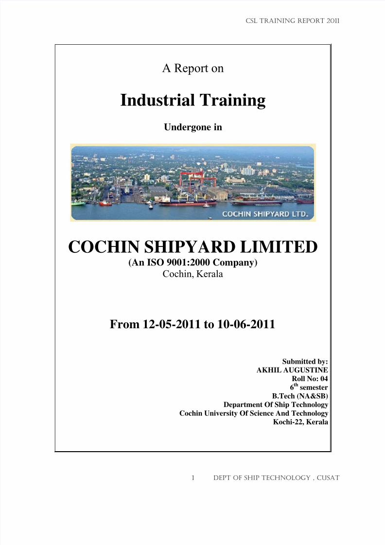
A Report on Industrial Training Undergone in COCHIN SHIPYARD LIMITED (An ISO 9001:2000 Company) Cochin, Kerala From 12-05-2011 to 10-06-2011 Submitted by: AKHIL AUGUSTINE Roll No: 04 6 th semester B.Tech (NA&SB) Department Of Ship Technology Cochin University Of Science And Technology Kochi-22, Kerala CSL TRAINING REPORT 2011 1 DEPT OF SHIP TECHNOLOGY , CUSAT
-
Upload
adarshkalladayil -
Category
Documents
-
view
238 -
download
0
Transcript of CSL FINAL_3
7/23/2019 CSL FINAL_3
http://slidepdf.com/reader/full/csl-final3 1/132
A Report on
Industrial Training
Undergone in
COCHIN SHIPYARD LIMITED(An ISO 9001:2000 Company)
Cochin, Kerala
From 12-05-2011 to 10-06-2011
Submitted by:
AKHIL AUGUSTINE
Roll No: 046th
semester
B.Tech (NA&SB)
Department Of Ship Technology
Cochin University Of Science And Technology
Kochi-22, Kerala
CSL TRAINING REPORT 2011
1 DEPT OF SHIP TECHNOLOGY , CUSAT
7/23/2019 CSL FINAL_3
http://slidepdf.com/reader/full/csl-final3 2/132
O H IN UN IV ERS ITY O F
S IEN E ND TE HNOLOGY
CSL TRAINING REPORT 2011
2 DEPT OF SHIP TECHNOLOGY , CUSAT
7/23/2019 CSL FINAL_3
http://slidepdf.com/reader/full/csl-final3 3/132
m~ ~
1 4 1 , , , ' ' ' ' I f. . . _
> f t • . . r . ; \ o r 1653, '1 ' > f t • . . r . . -682015
J J o s
p
. D eputy Gen era l Manag er Trg
Durin g th is p erio d h is c ondu ct an d ch arac ter are fou nd go od.
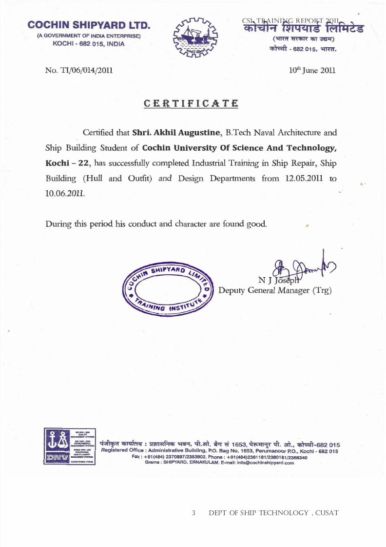
Cert ified that Shri. Akhil Augustine B.Tech Nava l Arch itectu re and
S hip B uildin g S tud ent o f Cochin University Of Science And Technology
Kochi
22,
has success fu llycomple ted Indus tr ia l T ra in ing in Sh ip Repa ir , Sh ip
Building Hull and Outfit and Design Departments from 12.0 5.2 011 to
10.06.2011.
CERTIFICATE
No. Tlj06j014j2011
O HIN
SHIPY R
LTD
C f i l ¬ I I l ill
q
til f , z J
m«f
m m C f iT ~
~ -682 015,
cqm:r.
A GOVERNMENTOF INDIA ENTERPRISE) .
KOCHI - 682 015, INDIA
CSL TRAINING REPORT 2011
7/23/2019 CSL FINAL_3
http://slidepdf.com/reader/full/csl-final3 4/132
CONTENTS
Page no
1.
Acknowledgement------------------------------------5
2.
Introduction-------------------------------------------7
3. Ship repair office-------------------------------------18
4. Procedure for repair a ship-----------------------22
5. Machine repair---------------------------------------31
6. List of machineries in csl---------------------------33
7. Electrical and instrumentation office-----------38
8.
Hull repair---------------------------------------------42
9.
CSL TRAINING REPORT 2011
4 DEPT OF SHIP TECHNOLOGY , CUSAT
7/23/2019 CSL FINAL_3
http://slidepdf.com/reader/full/csl-final3 5/132
ACKNOWLEDGEMENT
On this occasion I post my sincere prayers to the almighty, without whose grace Icould not have got a training seat in this great organization.
I also pledge my sincere regards for Mr. K.P.NARAYANAN, HEAD OF THE
DEPARTMENT, Mr. DILEEP KRISHNAN, Mr.MATHIAZHYAKAN TRAINING CO-
ORDINATOR, and all professors for permitting me to attend the training and doing
necessary help for that
Now it’s my turn to owe my gratitude to all who helped me out through out the part
and parcel of the training helping me out in all the works and guiding. First and foremost
I thank Mr.Madhu.S.Nair (DGM Marketing), Mr.N.J.Joseph DGM Training, under whom
I did my training in guiding me through out the training and giving me timely advices.
Next I thank all other members of the ship repair office, hull department, outfit
department for being very friendly with me and helping me learn from the training here.
I also thank Mr. Sunny Thomas (DGM hull), without whose help I could not have
achieved some knowledge in hull department. I would like to express my sincere thanks
and gratitude to Murugaian (DGM), Mr.Anoop R ,Mr.Vineeth N, Mr. Jimmy Vincent
and all other supervisors and workers for their valuable guidance and supports in hull
department
I also thank Mr. James Micle(DGM SRO), Mr.Jayan Thampi, Mr.Sajin P Samual
from ship repair office, Mr. Mani for providing me best of the knowledge from outfitdepartment.
I wanted to name each one of them who helped me out through out the training here.
But due to space constraints I am restricting and thanking one and all who helped me out
in the training
Lastly but not the least I thank my parents and all teachers without whose
encouragement I would not have been here. I also could not miss my friends who have
helped me lot in coming here.
CSL TRAINING REPORT 2011
5 DEPT OF SHIP TECHNOLOGY , CUSAT
7/23/2019 CSL FINAL_3
http://slidepdf.com/reader/full/csl-final3 6/132
INTRODUCTION
Cochin shipyard is established in 1969.This is the first Greenfield ship building yard in India. The yard commenced the shipbuilding operations in 1978 and ship
repair in 1981.The only yard which can repair an Air Defense Ship is Cochin
shipyard.ISO 9001-2000 certified for Design and manufacture of small & medium crafts
up to 900 GRTConstruction of ships upto 1,10,000 DWT
Repair of ships upto 1,25,000 DWT
Training of Marine Engineers & Conducting of fire fighting courses
Cochin Shipyard is an ISO 9001 Company, which has to its credit the biggestand most modern shipyard in India. This is the only yard, which has been set up as a
green field shipyard in 1972 and was conceived as a pioneer in establishing India in the
world shipbuilding scenario. Today, CSL is able to match the international standardsin quality, price and delivery schedules. There are two main sections in Cochin Shipyard.
First one is SHIP BUILDING SECTION (SB) and second one is SHIP REPAIR
SECTION (SR)
I have got training in the following sections:
1. Ship repair dept
2. Ship building dept
3. Ship design dept
CSL TRAINING REPORT 2011
6 DEPT OF SHIP TECHNOLOGY , CUSAT

7/23/2019 CSL FINAL_3
http://slidepdf.com/reader/full/csl-final3 7/132
PROFILE
Cochin shipyard is one of the leading shipbuilding & repair yard in India, which has aninfrastructure that combines economy, scale, and flexibility, and has ISO 9001
accreditation. CSL also has an exclusive area set for offshore construction and future
expansion.
As one of the India's top 10 public sector undertakings, CSL has been rated excellent
by the Government of India, four times in a row for achieving the targets set for the yard
under the MOU system
With specialized industry knowledge and superior resources, CSL has constantly
unfolded new levels of excellence in shipbuilding and ship repair. As a technology leader
in India, CSL has adopted the Japanese Integrated Hull Outfitting and Painting system(IHOP) for its new construction, which gives a clear edge to CSL in the field of
fabrication of commissioning of accommodation modules & topside modification.
AN OVERVIEW
Cochin Shipyard was incorporated in the year 1972 as a fully owned Government of
India company. In the last three decades the company has emerged as a forerunner in the
Indian shipbuilding & Ship repair industry. This yard can build and repair the largest
vessels in India. It can build ships up to 1,10,000 DWT and repair ships up to 1,25,0000
DWT. The yard has delivered two of India’s largest double hull Aframax tankers each of
95 000 DWT. CSL has secured shipbuilding orders from internationally renowned
companies from Europe & Middle East and is nominated to build the country’s first
indigenously built Air Defence Ship.
Shipyard commenced ship repair operations in the year 1982 and has undertaken repairs
of all types of ships including upgradation of ships of oil exploration industry as well as
periodical lay up repairs and life extension of ships of Navy, UTL, Coast Guard,
Fisheries and Port Trust besides merchant ships of SCI & ONGC. The yard has, over the
years, developed adequate capabilities to handle complex and sophisticated repair jobs.Recently Cochin Shipyard has bagged major repair orders from ONGC. The order for
major repairs of three rigs viz. Mobile Offshore Drilling Unit (MODU) Sagar Vijay,
Mobile Offshore Drilling Unit (MODU) Sagar Bhushan and Jack Up Rig (JUR) Sagar
Kiran was secured by CSL against very stiff international competition, thus achieving.
The Shipyard also trains graduate engineers to marine engineers who later join ships both
Indian and foreign as 5th Engineers. 100 are trained every year.
CSL TRAINING REPORT 2011
7 DEPT OF SHIP TECHNOLOGY , CUSAT
7/23/2019 CSL FINAL_3
http://slidepdf.com/reader/full/csl-final3 8/132
HISTORY
1. Cochin Shipyard was conceived of in the year 1969 when a team surveyed variouslocations in India before selecting Cochin for the launch of the first Greenfield
shipbuilding yard in the country.
2. The yard facilities in the first phase were completed by 1982. The yard was designed
and constructed under technical collaboration with M/s Mitsubishi Heavy Industries
(M.H.I), Japan. The company was legally incorporated in the year 1972.
3. The yard commenced the shipbuilding operations in 1978, ship repair in 1981, Marine
Engineering Training in 1993 and Offshore Upgradation in 1999.
4. Cochin Shipyard’s recent success in securing export orders have been achieved
through consistent improvement in productivity and also aggressive marketing
undertaken in the last few years.
5. The yard could reduce the average time of construction of large ships in the last decade
through augmentation of facilities, upgradation of ship design department with
installation of Tribon and CAD/CAM software and adoption of IHOP system of
construction.
6. The shipyard commenced ship repair operations in the year 1982 and has undertaken
repairs of all types of vessels including upgradation of ships of oil exploration industry as
well as periodical lay up repairs and life extension of ships of Navy, UTL, Coast Guard,
Fisheries and Port Trust besides merchant fleet. The yard has, over the years, developed
adequate capabilities to handle complex and sophisticated repair jobs.
Strategic Tie-Ups
7. CSL has established tie-ups with select specialist firms from near-east, far-east, South-
east, Europe and USA for technology transfer & material packages for shipbuilding, ship
repair, platforms, Rigs & Upgradation of yard facilities
CSL TRAINING REPORT 2011
8 DEPT OF SHIP TECHNOLOGY , CUSAT
7/23/2019 CSL FINAL_3
http://slidepdf.com/reader/full/csl-final3 9/132
CREDENTIALS
Shipbuilding
Only Shipyard in India which can build up to 1,10,000 DWT
Has built various types of vessels including Tankers, Bulk Carriers, Port Crafts,
Passenger Vessels etc
Reputed international clientele consisting of National Petroleum Construction Company,
Abu Dhabi, M/s Clipper, Bahamas, Jeddah Port Authority, Saudi Arabia & Sea tankers
Management, Norway.
Currently building 30000 DWT Bulk Carriers and Platform Supply Vessels
Shiprepair
Only Shipyard in India which can repair ships up to 1,25,000 DWT
The only yard which can repair an Air Defence Ship
Can undertake complex and sophisticated repairs to Oil Rigs; & ships of Navy, Coast
Guard & Merchant Navy
Secured three major projects from ONGC for repairs of Mobile Offshore Drilling Unit
(MODU) Sagar Vijay, Mobile Offshore Drilling Unit (MODU) Sagar Bhushan and Jack
Up Rig (JUR) Sagar Kiran in 2005-06.
Sagar Ratna repair-loading on to submersible barge 'Swan'
Offshore
Has undertaken a variety of complex and sophisticated offshore Upgradation contracts .
Others
Conducts Marine Engineering Training, Basic & Advance Fire Fighting Courses
ISO 9001-2000 certified for
Design and manufacture of small & medium crafts up to 900 GRT
Construction of ships up to 1,10,000 DWT
Repair of ships up to 1,25,000 DWT
Training of Marine Engineers & Conducting of fire fighting courses
Has a laboratory for destructive and non-destructive testing of material, chemical
analysis, oil-fuel testing, ultrasonic thickness gauging and other activities.
Complies with ISPS certification.
CSL TRAINING REPORT 2011
9 DEPT OF SHIP TECHNOLOGY , CUSAT
7/23/2019 CSL FINAL_3
http://slidepdf.com/reader/full/csl-final3 10/132
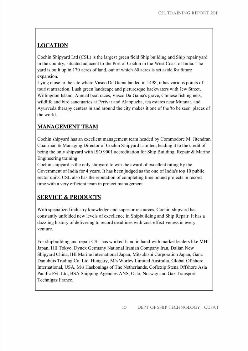
LOCATION
Cochin Shipyard Ltd (CSL) is the largest green field Ship building and Ship repair yard
in the country, situated adjacent to the Port of Cochin in the West Coast of India. The
yard is built up in 170 acres of land, out of which 60 acres is set aside for future
expansion.
Lying close to the site where Vasco Da Gama landed in 1498, it has various points of
tourist attraction. Lush green landscape and picturesque backwaters with Jew Street,
Willingdon Island, Annual boat races, Vasco Da Gama's grave, Chinese fishing nets,
wildlife and bird sanctuaries at Periyar and Alappuzha, tea estates near Munnar, and
Ayurveda therapy centers in and around the city makes it one of the 'to be seen' places of
the world.
MANAGEMENT TEAM
Cochin shipyard has an excellent management team headed by Commodore M. Jitendran,
Chairman & Managing Director of Cochin Shipyard Limited, leading it to the credit of
being the only shipyard with ISO 9001 accreditation for Ship Building, Repair & Marine
Engineering training
Cochin shipyard is the only shipyard to win the award of excellent rating by the
Government of India for 4 years. It has been judged as the one of India's top 10 public
sector units. CSL also has the reputation of completing time bound projects in record
time with a very efficient team in project management.
SERVICE & PRODUCTS
With specialized industry knowledge and superior resources, Cochin shipyard has
constantly unfolded new levels of excellence in Shipbuilding and Ship Repair. It has a
dazzling history of delivering to record deadlines with cost-effectiveness in every
venture.
For shipbuilding and repair CSL has worked hand in hand with market leaders like MHI
Japan, IHI Tokyo, Dynex Germany National Iranian Company Iran, Dalian New
Shipyard China, IHI Marine International Japan, Mitsubishi Corporation Japan, Ganz
Danubuis Trading Co. Ltd. Hungary, M/s Worley Limited Australia, Global Offshore
International, USA, M/s Haskonings of The Netherlands, Coflexip Stena Offshore Asia
Pacific Pvt. Ltd, BSA Shipping Agencies ANS, Oslo, Norway and Gaz Transport
Technigaz France.
CSL TRAINING REPORT 2011
10 DEPT OF SHIP TECHNOLOGY , CUSAT
7/23/2019 CSL FINAL_3
http://slidepdf.com/reader/full/csl-final3 11/132
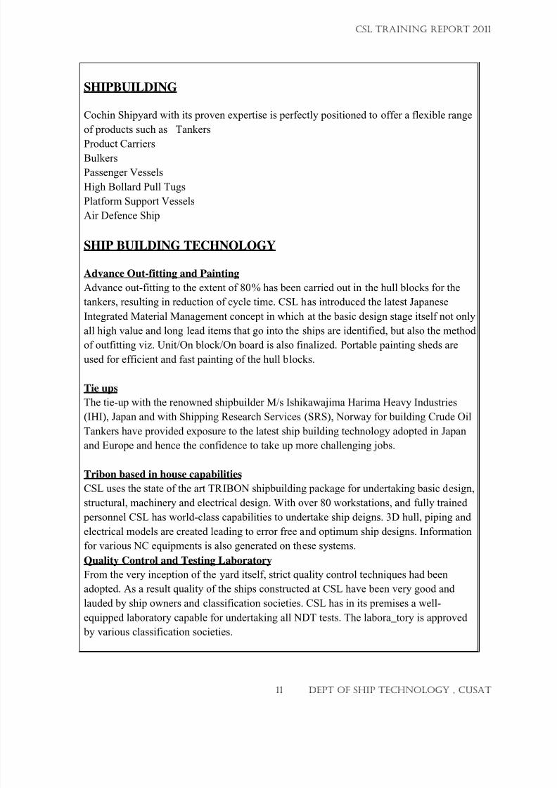
SHIPBUILDING
Cochin Shipyard with its proven expertise is perfectly positioned to offer a flexible range
of products such as Tankers
Product Carriers
Bulkers
Passenger Vessels
High Bollard Pull Tugs
Platform Support Vessels
Air Defence Ship
SHIP BUILDING TECHNOLOGY
Advance Out-fitting and PaintingAdvance out-fitting to the extent of 80% has been carried out in the hull blocks for the
tankers, resulting in reduction of cycle time. CSL has introduced the latest Japanese
Integrated Material Management concept in which at the basic design stage itself not only
all high value and long lead items that go into the ships are identified, but also the method
of outfitting viz. Unit/On block/On board is also finalized. Portable painting sheds are
used for efficient and fast painting of the hull blocks.
Tie ups
The tie-up with the renowned shipbuilder M/s Ishikawajima Harima Heavy Industries
(IHI), Japan and with Shipping Research Services (SRS), Norway for building Crude Oil
Tankers have provided exposure to the latest ship building technology adopted in Japan
and Europe and hence the confidence to take up more challenging jobs.
Tribon based in house capabilities
CSL uses the state of the art TRIBON shipbuilding package for undertaking basic design,
structural, machinery and electrical design. With over 80 workstations, and fully trained
personnel CSL has world-class capabilities to undertake ship deigns. 3D hull, piping and
electrical models are created leading to error free and optimum ship designs. Information
for various NC equipments is also generated on these systems.
Quality Control and Testing Laboratory
From the very inception of the yard itself, strict quality control techniques had been
adopted. As a result quality of the ships constructed at CSL have been very good and
lauded by ship owners and classification societies. CSL has in its premises a well-
equipped laboratory capable for undertaking all NDT tests. The labora_tory is approved
by various classification societies.
CSL TRAINING REPORT 2011
11 DEPT OF SHIP TECHNOLOGY , CUSAT

7/23/2019 CSL FINAL_3
http://slidepdf.com/reader/full/csl-final3 12/132
IMS
Integrated Management System is a system that guides the Organization through
the difficulties of managing compliance with multiple standards in the field of
environment, quality, health, safety, security etc. In CSL, IMS is a combined
Management System, which consists of standards such as ISO 9001:2008 (Quality
Management System), OHSAS 18001:2007 (Occupational Health, Safety Assessment
Series) and ISO 14001:2004 (Environmental Management System).
ISO 9001
ISO 9001 specifies requirements for a Quality Management System and requires an
organization to demonstrate its ability to consistently provide product that meets
customer and applicable statutory and regulatory requirements. This Management System
is already implemented in CSL and certified by third party certification body.
OHSAS 18001
OHSAS 18001 is a comprehensive Occupational Health and Safety Management System
specification, designed to enable organizations to control Health & Safety risks and
improve its Health & Safety performance. It enables an organization to have control over,
and knowledge of, all relevant hazards resulting from normal operations and abnormal
situations, and improve its performance.
ISO 14001
ISO 14001 is an International Standard that specifies a process for controlling and
improving a company’s environmental performance. This Management System addresses
the needs of broad range of interested parties and of society in general to protect the
environment.
CSL TRAINING REPORT 2011
12 DEPT OF SHIP TECHNOLOGY , CUSAT
7/23/2019 CSL FINAL_3
http://slidepdf.com/reader/full/csl-final3 13/132
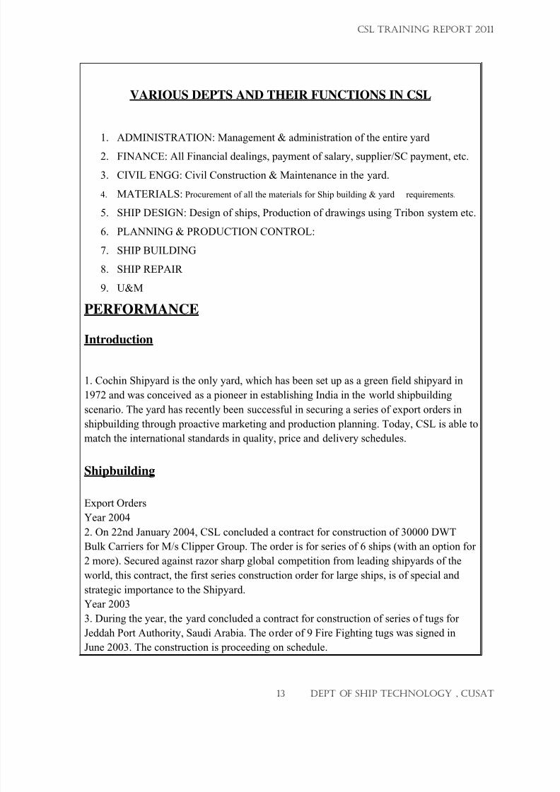
VARIOUS DEPTS AND THEIR FUNCTIONS IN CSL
1.
ADMINISTRATION: Management & administration of the entire yard
2. FINANCE: All Financial dealings, payment of salary, supplier/SC payment, etc.
3. CIVIL ENGG: Civil Construction & Maintenance in the yard.
4. MATERIALS: Procurement of all the materials for Ship building & yard requirements.
5. SHIP DESIGN: Design of ships, Production of drawings using Tribon system etc.
6. PLANNING & PRODUCTION CONTROL:
7. SHIP BUILDING
8. SHIP REPAIR
9. U&M
PERFORMANCE
Introduction
1. Cochin Shipyard is the only yard, which has been set up as a green field shipyard in
1972 and was conceived as a pioneer in establishing India in the world shipbuilding
scenario. The yard has recently been successful in securing a series of export orders in
shipbuilding through proactive marketing and production planning. Today, CSL is able to
match the international standards in quality, price and delivery schedules.
Shipbuilding
Export Orders
Year 2004
2. On 22nd January 2004, CSL concluded a contract for construction of 30000 DWT
Bulk Carriers for M/s Clipper Group. The order is for series of 6 ships (with an option for
2 more). Secured against razor sharp global competition from leading shipyards of the
world, this contract, the first series construction order for large ships, is of special and
strategic importance to the Shipyard.
Year 2003
3. During the year, the yard concluded a contract for construction of series of tugs for
Jeddah Port Authority, Saudi Arabia. The order of 9 Fire Fighting tugs was signed in
June 2003. The construction is proceeding on schedule.
CSL TRAINING REPORT 2011
13 DEPT OF SHIP TECHNOLOGY , CUSAT
7/23/2019 CSL FINAL_3
http://slidepdf.com/reader/full/csl-final3 14/132
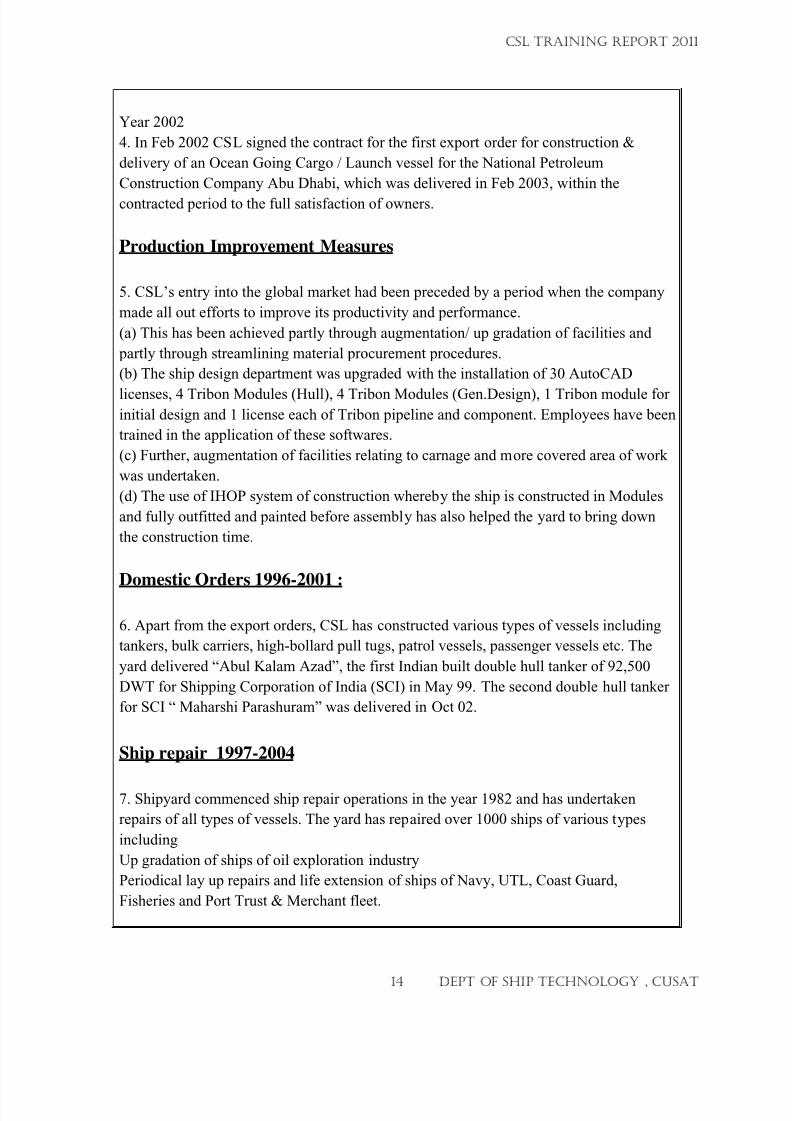
Year 2002
4. In Feb 2002 CSL signed the contract for the first export order for construction &
delivery of an Ocean Going Cargo / Launch vessel for the National Petroleum
Construction Company Abu Dhabi, which was delivered in Feb 2003, within the
contracted period to the full satisfaction of owners.
Production Improvement Measures
5. CSL’s entry into the global market had been preceded by a period when the company
made all out efforts to improve its productivity and performance.
(a) This has been achieved partly through augmentation/ up gradation of facilities and
partly through streamlining material procurement procedures.
(b) The ship design department was upgraded with the installation of 30 AutoCAD
licenses, 4 Tribon Modules (Hull), 4 Tribon Modules (Gen.Design), 1 Tribon module forinitial design and 1 license each of Tribon pipeline and component. Employees have been
trained in the application of these softwares.
(c) Further, augmentation of facilities relating to carnage and more covered area of work
was undertaken.
(d) The use of IHOP system of construction whereby the ship is constructed in Modules
and fully outfitted and painted before assembly has also helped the yard to bring down
the construction time.
Domestic Orders 1996-2001 :
6. Apart from the export orders, CSL has constructed various types of vessels including
tankers, bulk carriers, high-bollard pull tugs, patrol vessels, passenger vessels etc. The
yard delivered “Abul Kalam Azad”, the first Indian built double hull tanker of 92,500
DWT for Shipping Corporation of India (SCI) in May 99. The second double hull tanker
for SCI “ Maharshi Parashuram” was delivered in Oct 02.
Ship repair 1997-2004
7. Shipyard commenced ship repair operations in the year 1982 and has undertaken
repairs of all types of vessels. The yard has repaired over 1000 ships of various types
including
Up gradation of ships of oil exploration industry
Periodical lay up repairs and life extension of ships of Navy, UTL, Coast Guard,
Fisheries and Port Trust & Merchant fleet.
CSL TRAINING REPORT 2011
14 DEPT OF SHIP TECHNOLOGY , CUSAT
7/23/2019 CSL FINAL_3
http://slidepdf.com/reader/full/csl-final3 15/132
Repairs of vessels/ offshore structures of oil exploration/exploitation industry.
CSL is also authorized service center for Sulzer engines.
Have capabilities to handle complex and sophisticated repair jobs.
METI
8. The Marine Engineering Training Institute (METI) was set up by CSL in the year 1993
for imparting Marine Engineering Training to Mechanical Engineers. The institute has so
far trained over 950 trainees since inception, manning ships all over the world and
functions as a profit center. The institute also imparts basic and advance fire fighting
courses and would soon commence courses on Personal Safety Techniques, Personal
Safety and Social Responsibilities and Elementary First Aid.
Net Worth:
9. The net worth of the company has steadily increased to reach a level of Rs 255.66 crs
in the year 2002-03.
CSL TRAINING REPORT 2011
15 DEPT OF SHIP TECHNOLOGY , CUSAT
7/23/2019 CSL FINAL_3
http://slidepdf.com/reader/full/csl-final3 16/132
SHIP REPAIR DEPARTMENT
(12/05/2011 – 20/05/2011)
CSL TRAINING REPORT 2011
16 DEPT OF SHIP TECHNOLOGY , CUSAT
7/23/2019 CSL FINAL_3
http://slidepdf.com/reader/full/csl-final3 17/132
Y
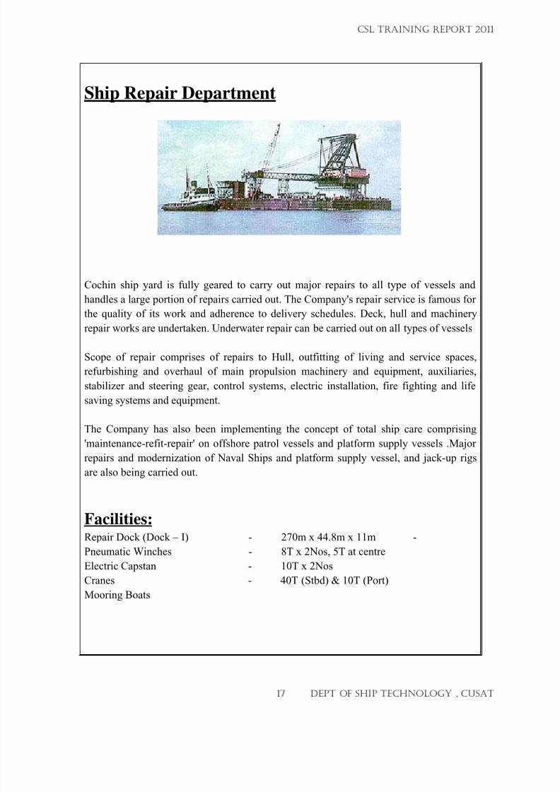
Ship Repair Department
Cochin ship yard is fully geared to carry out major repairs to all type of vessels and
handles a large portion of repairs carried out. The Company's repair service is famous for
the quality of its work and adherence to delivery schedules. Deck, hull and machinery
repair works are undertaken. Underwater repair can be carried out on all types of vessels
Scope of repair comprises of repairs to Hull, outfitting of living and service spaces,
refurbishing and overhaul of main propulsion machinery and equipment, auxiliaries,
stabilizer and steering gear, control systems, electric installation, fire fighting and life
saving systems and equipment.
The Company has also been implementing the concept of total ship care comprising
'maintenance-refit-repair' on offshore patrol vessels and platform supply vessels .Major
repairs and modernization of Naval Ships and platform supply vessel, and jack-up rigs
are also being carried out.
Facilities:Repair Dock (Dock – I) - 270m x 44.8m x 11m -
Pneumatic Winches - 8T x 2Nos, 5T at centreElectric Capstan - 10T x 2Nos
Cranes - 40T (Stbd) & 10T (Port)
Mooring Boats
CSL TRAINING REPORT 2011
17 DEPT OF SHIP TECHNOLOGY , CUSAT
7/23/2019 CSL FINAL_3
http://slidepdf.com/reader/full/csl-final3 18/132
ISRS (Integrated Ship Repair System)
This is a computer network connecting all the Depts of SR like SRP&M, SRC, SRO,
SR(E&OS) with a main server. This provide a quick and realistic data about all the
activities of SR.
When the RS of the vessel is received, SRC enter the same into the system.
Quotation is prepared for the vessel in the same way in computer formats.
All the Depts have access to these data for reference and can make advance arrangements
like indenting, procurement of matls. Indents are raised in the formats given in the
computer by SRO. SRM, referring to the indents on computer arrange to procure the
items. Enquiry, quotations, approval, PO and receipt of materials. SRC refer these data
for preparing invoice.
Highlights
ISRS is used for Standardising of Ship Repair activities and linking Tariff Rates and the
Sub Contractor Guidance Rates with the Activities to automate the Quotation
preparation, Work Completion Certificate preparation, Invoice preparation and Sub
Contract Bill verification. This area was totally unstructured and they were able to create
around 10000 SR activities which forms the basis of all the activities at Cochin Shipyard.
Goal and Objectives
Cost Reduction in Ship Repair Operations
Better Material Management
Better Sub Contract Management
Better Labor Management
Faster preparation of Quotations & Invoices
Creation of Database for future quotations
Sharing of information among various agencies like commercial, planning & operations
CSL TRAINING REPORT 2011
18 DEPT OF SHIP TECHNOLOGY , CUSAT
7/23/2019 CSL FINAL_3
http://slidepdf.com/reader/full/csl-final3 19/132
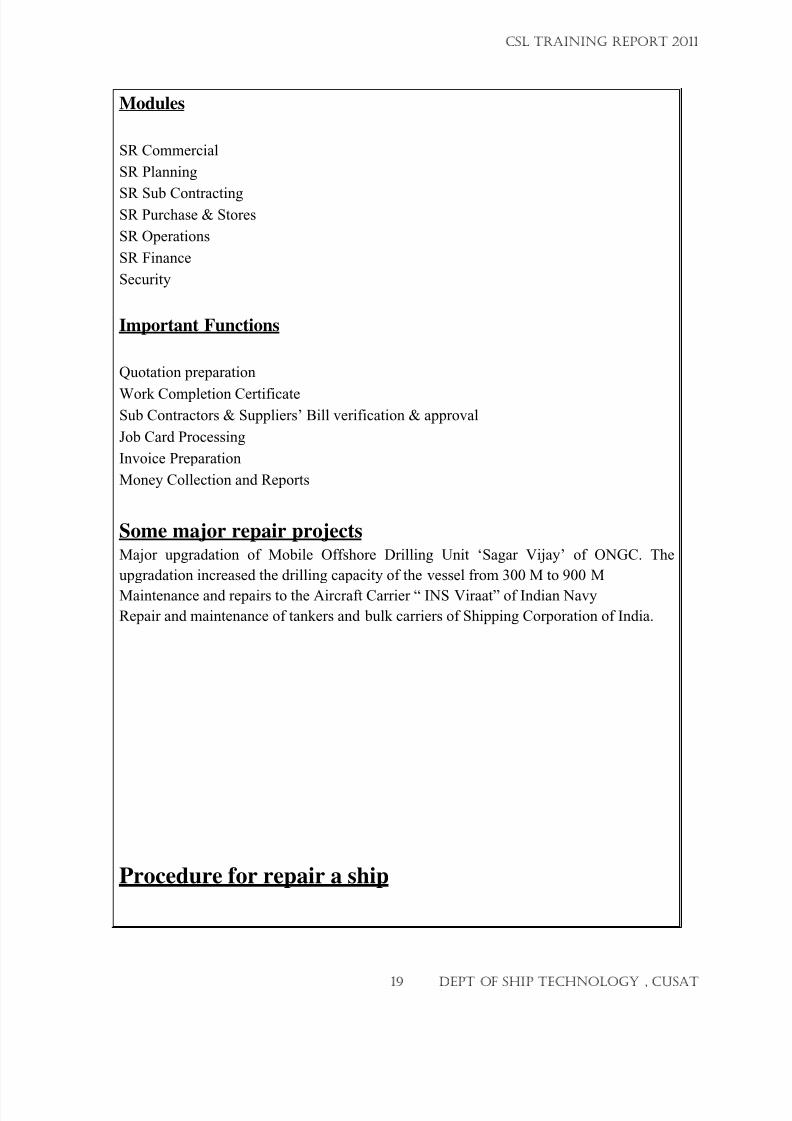
Modules
SR Commercial
SR Planning
SR Sub ContractingSR Purchase & Stores
SR Operations
SR Finance
Security
Important Functions
Quotation preparation
Work Completion CertificateSub Contractors & Suppliers’ Bill verification & approval
Job Card Processing
Invoice Preparation
Money Collection and Reports
Some major repair projects Major upgradation of Mobile Offshore Drilling Unit ‘Sagar Vijay’ of ONGC. The
upgradation increased the drilling capacity of the vessel from 300 M to 900 M
Maintenance and repairs to the Aircraft Carrier “ INS Viraat” of Indian Navy
Repair and maintenance of tankers and bulk carriers of Shipping Corporation of India.
Procedure for repair a ship
CSL TRAINING REPORT 2011
19 DEPT OF SHIP TECHNOLOGY , CUSAT
7/23/2019 CSL FINAL_3
http://slidepdf.com/reader/full/csl-final3 20/132
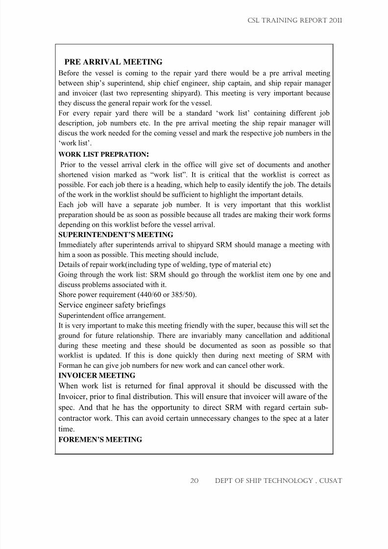
PRE ARRIVAL MEETING Before the vessel is coming to the repair yard there would be a pre arrival meeting
between ship’s superintend, ship chief engineer, ship captain, and ship repair manager
and invoicer (last two representing shipyard). This meeting is very important becausethey discuss the general repair work for the vessel.
For every repair yard there will be a standard ‘work list’ containing different job
description, job numbers etc. In the pre arrival meeting the ship repair manager will
discus the work needed for the coming vessel and mark the respective job numbers in the
‘work list’.
WORK LIST PREPRATION:
Prior to the vessel arrival clerk in the office will give set of documents and another
shortened vision marked as “work list”. It is critical that the worklist is correct as
possible. For each job there is a heading, which help to easily identify the job. The details
of the work in the worklist should be sufficient to highlight the important details.
Each job will have a separate job number. It is very important that this worklist
preparation should be as soon as possible because all trades are making their work forms
depending on this worklist before the vessel arrival.
SUPERINTENDENT’S MEETING
Immediately after superintends arrival to shipyard SRM should manage a meeting with
him a soon as possible. This meeting should include,
Details of repair work(including type of welding, type of material etc)
Going through the work list: SRM should go through the worklist item one by one and
discuss problems associated with it.Shore power requirement (440/60 or 385/50).
Service engineer safety briefings
Superintendent office arrangement.
It is very important to make this meeting friendly with the super, because this will set the
ground for future relationship. There are invariably many cancellation and additional
during these meeting and these should be documented as soon as possible so that
worklist is updated. If this is done quickly then during next meeting of SRM with
Forman he can give job numbers for new work and can cancel other work.
INVOICER MEETING
When work list is returned for final approval it should be discussed with theInvoicer, prior to final distribution. This will ensure that invoicer will aware of the
spec. And that he has the opportunity to direct SRM with regard certain sub-
contractor work. This can avoid certain unnecessary changes to the spec at a later
time.
FOREMEN’S MEETING
CSL TRAINING REPORT 2011
20 DEPT OF SHIP TECHNOLOGY , CUSAT
7/23/2019 CSL FINAL_3
http://slidepdf.com/reader/full/csl-final3 21/132
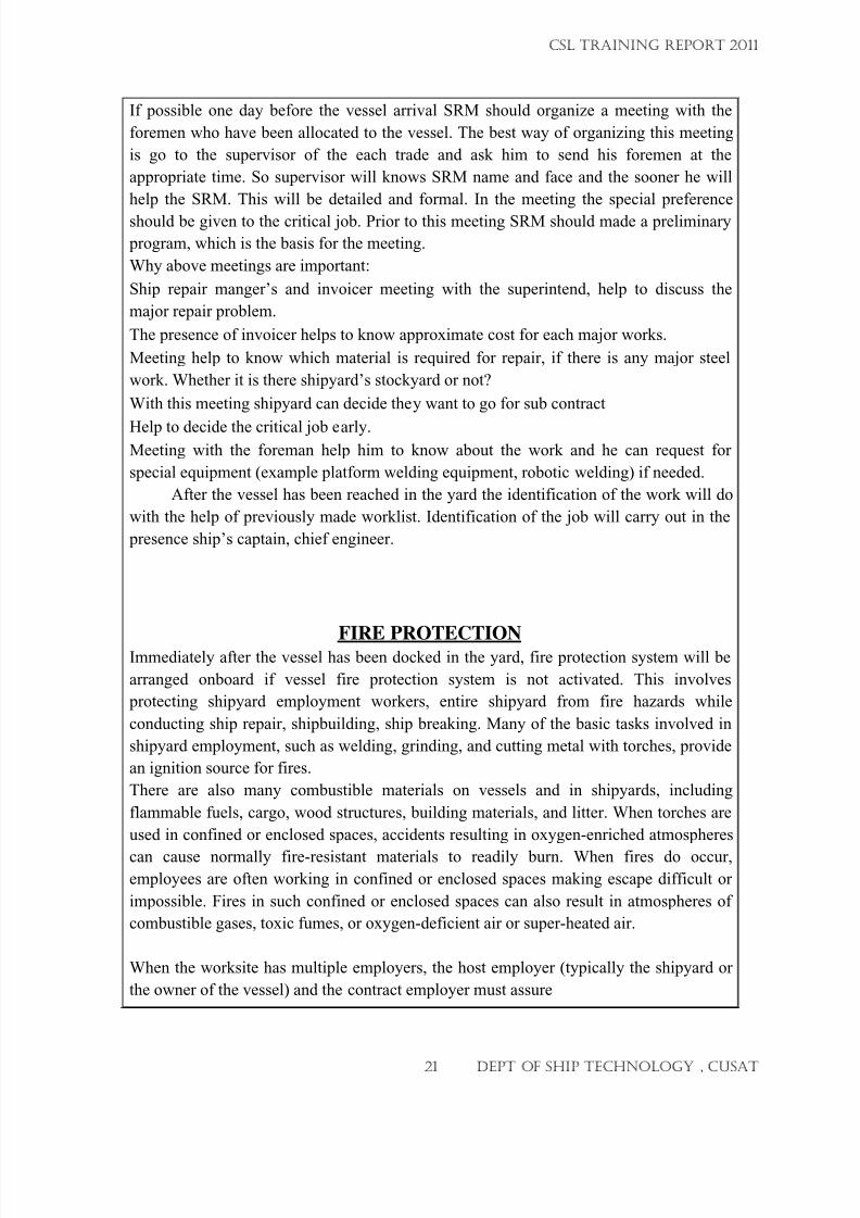
If possible one day before the vessel arrival SRM should organize a meeting with the
foremen who have been allocated to the vessel. The best way of organizing this meeting
is go to the supervisor of the each trade and ask him to send his foremen at the
appropriate time. So supervisor will knows SRM name and face and the sooner he will
help the SRM. This will be detailed and formal. In the meeting the special preference
should be given to the critical job. Prior to this meeting SRM should made a preliminary
program, which is the basis for the meeting.
Why above meetings are important:
Ship repair manger’s and invoicer meeting with the superintend, help to discuss the
major repair problem.
The presence of invoicer helps to know approximate cost for each major works.
Meeting help to know which material is required for repair, if there is any major steel
work. Whether it is there shipyard’s stockyard or not?
With this meeting shipyard can decide they want to go for sub contract
Help to decide the critical job early.Meeting with the foreman help him to know about the work and he can request for
special equipment (example platform welding equipment, robotic welding) if needed.
After the vessel has been reached in the yard the identification of the work will do
with the help of previously made worklist. Identification of the job will carry out in the
presence ship’s captain, chief engineer.
FIRE PROTECTIONImmediately after the vessel has been docked in the yard, fire protection system will be
arranged onboard if vessel fire protection system is not activated. This involves
protecting shipyard employment workers, entire shipyard from fire hazards while
conducting ship repair, shipbuilding, ship breaking. Many of the basic tasks involved in
shipyard employment, such as welding, grinding, and cutting metal with torches, provide
an ignition source for fires.
There are also many combustible materials on vessels and in shipyards, including
flammable fuels, cargo, wood structures, building materials, and litter. When torches are
used in confined or enclosed spaces, accidents resulting in oxygen-enriched atmospheres
can cause normally fire-resistant materials to readily burn. When fires do occur,employees are often working in confined or enclosed spaces making escape difficult or
impossible. Fires in such confined or enclosed spaces can also result in atmospheres of
combustible gases, toxic fumes, or oxygen-deficient air or super-heated air.
When the worksite has multiple employers, the host employer (typically the shipyard or
the owner of the vessel) and the contract employer must assure
CSL TRAINING REPORT 2011
21 DEPT OF SHIP TECHNOLOGY , CUSAT
7/23/2019 CSL FINAL_3
http://slidepdf.com/reader/full/csl-final3 22/132
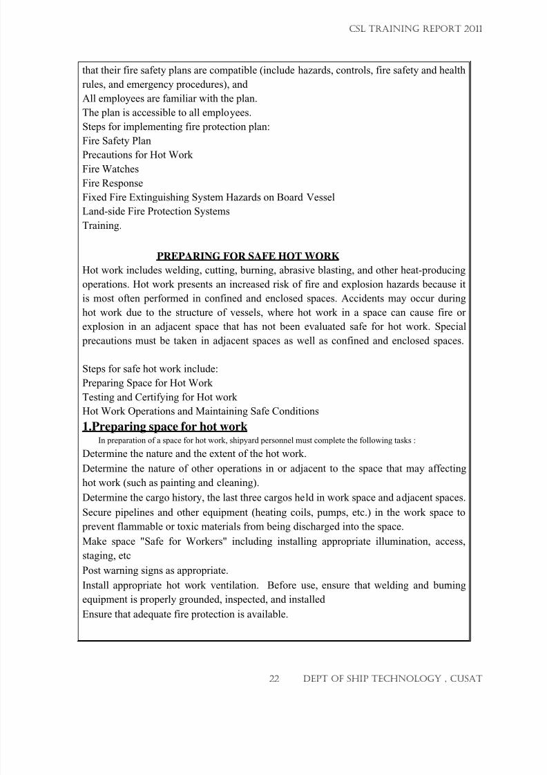
that their fire safety plans are compatible (include hazards, controls, fire safety and health
rules, and emergency procedures), and
All employees are familiar with the plan.
The plan is accessible to all employees.
Steps for implementing fire protection plan:
Fire Safety Plan
Precautions for Hot Work
Fire Watches
Fire Response
Fixed Fire Extinguishing System Hazards on Board Vessel
Land-side Fire Protection Systems
Training.
PREPARING FOR SAFE HOT WORK
Hot work includes welding, cutting, burning, abrasive blasting, and other heat-producingoperations. Hot work presents an increased risk of fire and explosion hazards because it
is most often performed in confined and enclosed spaces. Accidents may occur during
hot work due to the structure of vessels, where hot work in a space can cause fire or
explosion in an adjacent space that has not been evaluated safe for hot work. Special
precautions must be taken in adjacent spaces as well as confined and enclosed spaces.
Steps for safe hot work include:
Preparing Space for Hot Work
Testing and Certifying for Hot work
Hot Work Operations and Maintaining Safe Conditions
1.Preparing space for hot workIn preparation of a space for hot work, shipyard personnel must complete the following tasks :
Determine the nature and the extent of the hot work.
Determine the nature of other operations in or adjacent to the space that may affecting
hot work (such as painting and cleaning).
Determine the cargo history, the last three cargos held in work space and adjacent spaces.
Secure pipelines and other equipment (heating coils, pumps, etc.) in the work space to
prevent flammable or toxic materials from being discharged into the space.
Make space "Safe for Workers" including installing appropriate illumination, access,staging, etc
Post warning signs as appropriate.
Install appropriate hot work ventilation. Before use, ensure that welding and burning
equipment is properly grounded, inspected, and installed
Ensure that adequate fire protection is available.
CSL TRAINING REPORT 2011
22 DEPT OF SHIP TECHNOLOGY , CUSAT
7/23/2019 CSL FINAL_3
http://slidepdf.com/reader/full/csl-final3 23/132
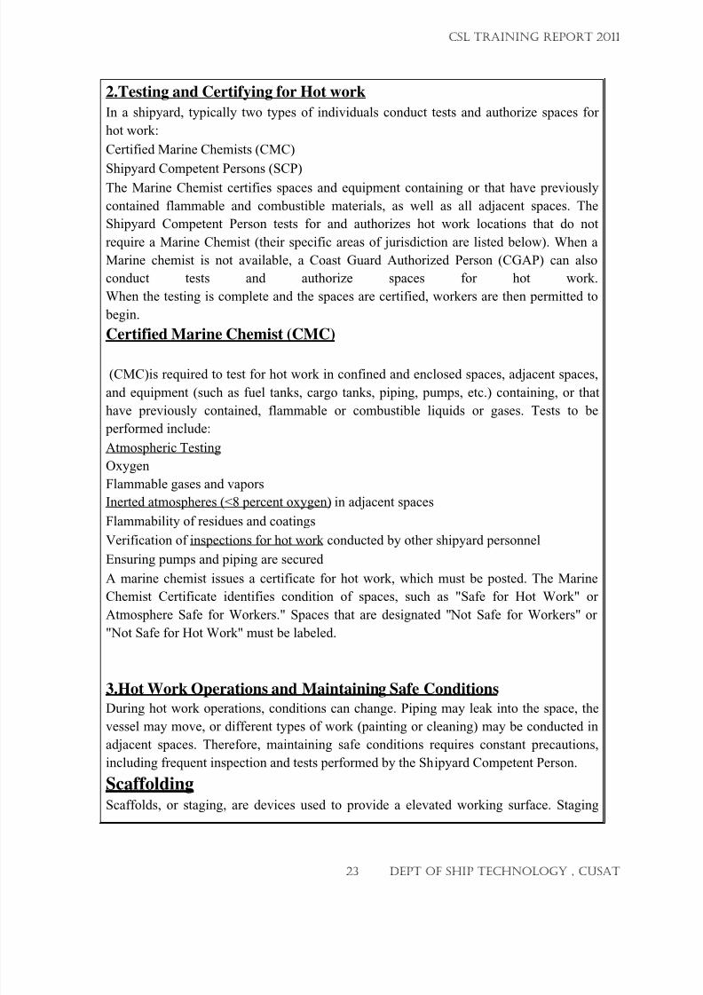
2.Testing and Certifying for Hot work
In a shipyard, typically two types of individuals conduct tests and authorize spaces for
hot work:
Certified Marine Chemists (CMC)
Shipyard Competent Persons (SCP)The Marine Chemist certifies spaces and equipment containing or that have previously
contained flammable and combustible materials, as well as all adjacent spaces. The
Shipyard Competent Person tests for and authorizes hot work locations that do not
require a Marine Chemist (their specific areas of jurisdiction are listed below). When a
Marine chemist is not available, a Coast Guard Authorized Person (CGAP) can also
conduct tests and authorize spaces for hot work.
When the testing is complete and the spaces are certified, workers are then permitted to
begin.
Certified Marine Chemist (CMC)
(CMC)is required to test for hot work in confined and enclosed spaces, adjacent spaces,
and equipment (such as fuel tanks, cargo tanks, piping, pumps, etc.) containing, or that
have previously contained, flammable or combustible liquids or gases. Tests to be
performed include:
Atmospheric Testing
Oxygen
Flammable gases and vapors
Inerted atmospheres (<8 percent oxygen) in adjacent spaces
Flammability of residues and coatingsVerification of inspections for hot work conducted by other shipyard personnel
Ensuring pumps and piping are secured
A marine chemist issues a certificate for hot work, which must be posted. The Marine
Chemist Certificate identifies condition of spaces, such as "Safe for Hot Work" or
Atmosphere Safe for Workers." Spaces that are designated " Not Safe for Workers" or
"Not Safe for Hot Work " must be labeled.
3.Hot Work Operations and Maintaining Safe Conditions
During hot work operations, conditions can change. Piping may leak into the space, the
vessel may move, or different types of work (painting or cleaning) may be conducted in
adjacent spaces. Therefore, maintaining safe conditions requires constant precautions,
including frequent inspection and tests performed by the Shipyard Competent Person.
ScaffoldingScaffolds, or staging, are devices used to provide a elevated working surface. Staging
CSL TRAINING REPORT 2011
23 DEPT OF SHIP TECHNOLOGY , CUSAT
7/23/2019 CSL FINAL_3
http://slidepdf.com/reader/full/csl-final3 24/132
may be of several different designs and is often constructed to fit the ship. Staging must
be adequate for the work performed because falls are a significant hazard in the shipyard.
Before working on or near any scaffold, workers should ensure that scaffolds are:
Safely secured and supported,
Level,
Provided with safe access (such as ladders),
Adequately decked (for example have a work surface and platform), and
Provided with guard rails.
Scaffolding, or staging, presents hazards for personnel working from, accessing, or
leaving a scaffold. To be safe, scaffolding must be constructed from specified materials
in an approved manner. Fall protection must be provided for the workers on the scaffold.
Protection from falling objects must be provided for workers below the scaffold.
Potential Hazards:
Failure of the staging components or overloading may result in collapse of the unit in
whole or in part, causing workers to fall.
Workers falling off the staging due to lack of edge guards.
Items falling off the staging and injuring workers below.
Surging (for example movement of work surface) when working on floating scaffolds.
Workers on the scaffolds falling to the level below.
Items falling from the scaffolds and striking workers below.
Requirements
All scaffolds and their supports must be capable of supporting the load they are designed
to carry with a safety factor of no less than four.All lumber (such as scaffold grade, used in the construction of scaffolds must be sound,
straight, and free from defects.
Scaffolds shall be maintained in a safe and secure condition. Any component of the
scaffold that is broken, burned, or otherwise defective must be replaced.
Unstable objects (such as Barrels, boxes, cans, or loose bricks) must not be used as
working platforms, or to support working platforms.
Scaffolds must be erected, moved, dismantled, or altered under the supervision of
scaffold competent persons.
Welding, burning, riveting, or open flame work must not be performed on any staging
suspended by means of fiber rope.
Note: Wire rope can be easily damaged by hot work.
Lifting bridles on working platforms suspended from cranes must consist of four legs so
that the stability of the platform is assured.
CSL TRAINING REPORT 2011
24 DEPT OF SHIP TECHNOLOGY , CUSAT
7/23/2019 CSL FINAL_3
http://slidepdf.com/reader/full/csl-final3 25/132
ACCESSIBILITY PROBLEM, SPECIAL EQUIPMENT Certain part of the ship will have less access for hot work. This will lead to poor
quality welding. In order to avoid such prolonged tedious access welding some special
equipment are now introduced. One example for this type is welding platform
equipment.
Welding platform
Prolonged, tedious, and/or difficult-access welding can result in:
reduced weld quality
inefficient labor (minimal torch-on time)
worker fatigue
Plate Removal And Installation
A generalized procedure for the installation and repair of plates has been
prepared through a detailed analysis of the steps followed in various shipyards.
Steps involved are:
Pre arrival time:
If there is a major steel work, this matter will be discussed in the meeting between SRM
and superintendent.
Discuss accessibility problem with superintendent and arrange suitable equipment and
welder.
According to the norms set by the superintendent, arrange for the required steel.(grade of
steel, plate thickness)
CSL TRAINING REPORT 2011
25 DEPT OF SHIP TECHNOLOGY , CUSAT
7/23/2019 CSL FINAL_3
http://slidepdf.com/reader/full/csl-final3 26/132
Check whether it is in stockyard otherwise order for it immediately.
Check whether the work can be carried out by the shipyard work force or if any needs for
subcontracting exists.
After vessel arrival:
1) A gas inspector should check the area and check whether the entry is
safe.
Clean the area as required until safety inspector provides the “safety to entry & hot work
permit” pass.
3) Report to staging foreman for scaffolding in this area.
3) Identify the work with plate fitter (foreman) by using worklist.
4) Prepare the area for hot work as described above.
o Proper cleaning
o
Hot work permito Proper ventilation..
Remove paint within 500mm area if paint is toxic at high temperature.
Determine the nature of other operations in or adjacent to the space that may affect hot
work (such as painting and cleaning). Etc
Removal of the plate:
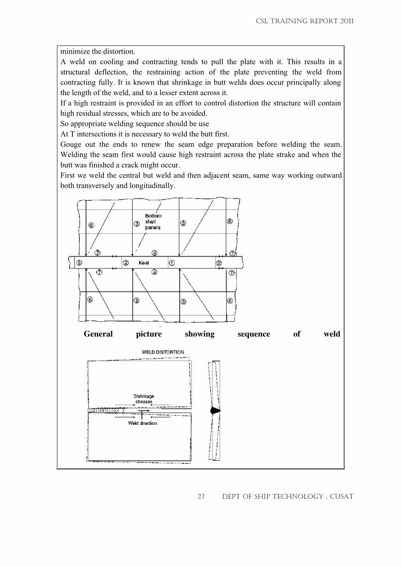
Make a production drawing as shown below which shows the sequence of weld and
dimension of the cut etc.
Check the area and mark the area to be cut out
General approach is that if a new shell plate is to be welded in place, the seams and butts
in the surrounding structure are cut back 300 to 375 mm from the opening.
Same way stiffeners are also cut back 300-375mm from the opening.
Using gas cutting torch cut the portion along the marking.
el
As decide early, arrange the plate and fabricate according to the drawing.
During welding distortion will occur. So we have to follow a welding sequence to
CSL TRAINING REPORT 2011
26 DEPT OF SHIP TECHNOLOGY , CUSAT
7/23/2019 CSL FINAL_3
http://slidepdf.com/reader/full/csl-final3 27/132
W L ISTORTION
c
\
\
\
Sh rink age
str e sses
_ J
. ...
We ld di rection
I
L
ottom
sh e ll ®
panels
minimize the distortion.
A weld on cooling and contracting tends to pull the plate with it. This results in a
structural deflection, the restraining action of the plate preventing the weld from
contracting fully. It is known that shrinkage in butt welds does occur principally along
the length of the weld, and to a lesser extent across it.
If a high restraint is provided in an effort to control distortion the structure will contain
high residual stresses, which are to be avoided.
So appropriate welding sequence should be use
At T intersections it is necessary to weld the butt first.
Gouge out the ends to renew the seam edge preparation before welding the seam.
Welding the seam first would cause high restraint across the plate strake and when the
butt was finished a crack might occur.
First we weld the central but weld and then adjacent seam, same way working outward
both transversely and longitudinally.
General picture showing sequence of weld
CSL TRAINING REPORT 2011
27 DEPT OF SHIP TECHNOLOGY , CUSAT
7/23/2019 CSL FINAL_3
http://slidepdf.com/reader/full/csl-final3 28/132
Weld pad eye to the panel for lifting(make suitable lifting calculation if panel is
big)
Machine repair
We saw the warship “nireekshak” we entered in to the engine room, the instructor
taught the main parts in the engine room
Engine room contains different parts that is
1. Propulsion system 8. Hydraulic system
2. LO system 9. Comp air system
3. CW system 10. Fire Fighting system
4. FW system
Propulsion system is mainly by using diesel engine
2nd psv -platform supply vessel it is used for rigging. While rigging it has to supply the
cements so in the ship there is a large chamber.
Engine and Machine Shop
This shop is equipped with modern machine tools like Plano miller (up to 30 T)
Bar Boring equipment (up to 300 mm dia), Inside Grinding machine (up to 300 mm dia),
Heavy Duty Lathes (up to 12M length), Horizontal Drilling machine ( up to 100 mm
boring & 600 mm drilling), Shrinkage equipment (up to 6 M x 900 mm O.D), Cylindrical
Grinding machine (630 mm dia x 2 T), Horizontal Boring machine (up to 560 mm dia),
CSL TRAINING REPORT 2011
28 DEPT OF SHIP TECHNOLOGY , CUSAT
7/23/2019 CSL FINAL_3
http://slidepdf.com/reader/full/csl-final3 29/132
Dynamic Balancing machine (up to 3 T) etc.
List of machineries in csl
1. Cranes
a. Gantry cranes-300t and 150t
b. semi-gantry
c. Level Luffing Tower Traveler (LLTT)
d. Electric Overhead traveler (EOT)
2. Travellin stages(2nos in port side & 2 nos in star board side)
3. Pumping Equipments
a.MDP (Main Discharge Pump)
b.Ballast Pump
c.Bilge Pump
d.Mud Pump
e.Gate Winch
f.Pneumatic Winch
g.Hauling Carriage
4. Machine Tools
a.Planomiller
b.Horizontal Drilling Machine
c.Radial Drilling Machine
d.Horizontal boring machine
e.12m lathe
CSL TRAINING REPORT 2011
29 DEPT OF SHIP TECHNOLOGY , CUSAT
7/23/2019 CSL FINAL_3
http://slidepdf.com/reader/full/csl-final3 30/132
f.5m lathe
g.2m lathe
h.Capstan lathe
i.Cylindrical Grinder
j.Dynamic Balancing Machine
k.Vertical Milling machine
i.Shaper
m.Slotter etc.
5. Washing / blasting machine
a.Densin 250 kg
b.Densin 2500 kg
c.Rocky Washer
Machinery details
Lathes
Different lathes are in our machine shop like 12m lathe,5m lathe,2m lathe, capstan latheetc.
A.12m lathe (HEC model)
centre height :800mm
max swing over bed :1600mm
max swing over carriage :1200mm
width of bed :1700mm
max weight of work piece without rest :28000kg
max weight of work piece with rest :38000kg
Generally the Preventive maintenance includes oiling, greasing and removing the metal
chips from bed etc.
B.5m lathe-HEC model-LC 100
CSL TRAINING REPORT 2011
30 DEPT OF SHIP TECHNOLOGY , CUSAT
7/23/2019 CSL FINAL_3
http://slidepdf.com/reader/full/csl-final3 31/132
Centre height :500mm
Swing over bed :1000mm
Swing over carriage :710mm
Max weight of work piece without rest :10t
Generally the Preventive maintenance includes oiling, greasing and removing the metal
chips from bed etc.
C.2m lathe-B26 HMT
Centre height :260mm
Spindle bore :42mm
Generally the Preventive maintenance includes oiling. Once we did gear box over
hauling
D.Capstan lathe-HYEBERT MK4
Swing over bed :375mm
max swing close to cross line :330mm
2. Planomiller-KOTOBUKI
M/S. Kotobuki Industries, Japan make, Double column type with one milling
head each one side columns and one swiveling milling head and one boring
head on the cross slide.
Working width : 2150 mm
working height : 2000 mm
Stroke of working table :5400mm
Boring capacity in steel :45 to 450 mm dia
Drilling capacity in steel :45mm dia
Usually oil checking and greasing is done as preventive maintenance
3. Horizontal drilling machine-SHIBURA
Drilling capacity :100mm dia
Boring capacity upto :600mm dia
Milling capacity up to :300mm dia
Taping capacity up to :100mm dia
Spindle stroke :600mm
Ram stroke :300mm
Horizontal traverse :1500mm
CSL TRAINING REPORT 2011
31 DEPT OF SHIP TECHNOLOGY , CUSAT
7/23/2019 CSL FINAL_3
http://slidepdf.com/reader/full/csl-final3 32/132
Vertical traverse :1500mm
Radial drilling machine-HEC
Max dia of hole drilled in steel of 60 kg/mm2Tensile strength :100mm
Max dia of hole drilled in cast iron of 25 kg/mm2
Tensile strength :125mm
Max dia of hole bored in steel of 60 kg/mm2
Tensile strength :350mm
Oiling and removing the scrap chips are the usual preventive maintenance methods
5. Vertical milling machine-HMT
Longitudinal traverse :1400mm
Cross traverse :360mm
Vertical traverse :475mm
Vertical quill movement :100mm
Max weight that can be loaded on the
Table :1000kg
Usually oil checking and greasing is done as preventive maintenance
6. Surface grinder OKAMOTOMax grinding length :1200mm
Max grinding width :500mm
Max longitudinal movement :1300mm
Max cross movement :530mm
Replacement of grinding wheel has been done when it got broke up
7. Slotting machine-COOPER
Max stroke :400mmDia of circular table :800mm
Swivel of ram :10 degree
8. Dynamic balancing machine
Rectangular jobs :250*175
Square jobs :175*175
CSL TRAINING REPORT 2011
32 DEPT OF SHIP TECHNOLOGY , CUSAT
7/23/2019 CSL FINAL_3
http://slidepdf.com/reader/full/csl-final3 33/132
Round jobs :175mm dia
9. Gantry cranes
There are two Gantry cranes;150t and 300t
Details of 300t gantry
Total load :300t(upper crab-180t and lower crab-120t)
Travelling speed :40m/min
Total height :75m
Width :95m
Preventive maintenance include greasing of rails and gears oil checking and checking of
rope
10. Main Discharge Pump(MDP)
Three MDPs each in the repair dock as well as in the building dock.
MDP in repair dock :It is bigger than those in building dock,made by Kirloskar,It is a
vertical turbine pump,Slow speed gear box is made use here,There is a mechanism
known as Ratchet pin which prevents the rotation due to the back flow of water.
11. Gate Winch(2 nos in the repair dock)
Each gate winch consists of electric motor as the driving unit. Output shaft of driving
unit is connected to one gear box which partially reduces the speed. The gear box output
again connected to 2 sets of open reduction gear units by which the speed is againreduced. The
final Output shaft at this stage is connected to a gypsy wheel by means of a geared
coupling in between the gypsy is overlapped by a chain which is in turn is connected to
the gate.
Type : Horizontal, electrically driven type
Motor : Induction motor, pole changing type special insulation against moisture and
tropical climate and with electromagnetic disc break.
The preventive maintenance includes greasing and bearing checking.
12. Mud Pump(2nos in repair dock and 1no Building dock)It is used to pump out the mud. manufactured by TOYO DENKI Industrial co,Ltd,Japan.
We use the model DP 50.
CSL TRAINING REPORT 2011
33 DEPT OF SHIP TECHNOLOGY , CUSAT
7/23/2019 CSL FINAL_3
http://slidepdf.com/reader/full/csl-final3 34/132
ote
Ty pically a ll leve ls
may be fed by
mor th n on
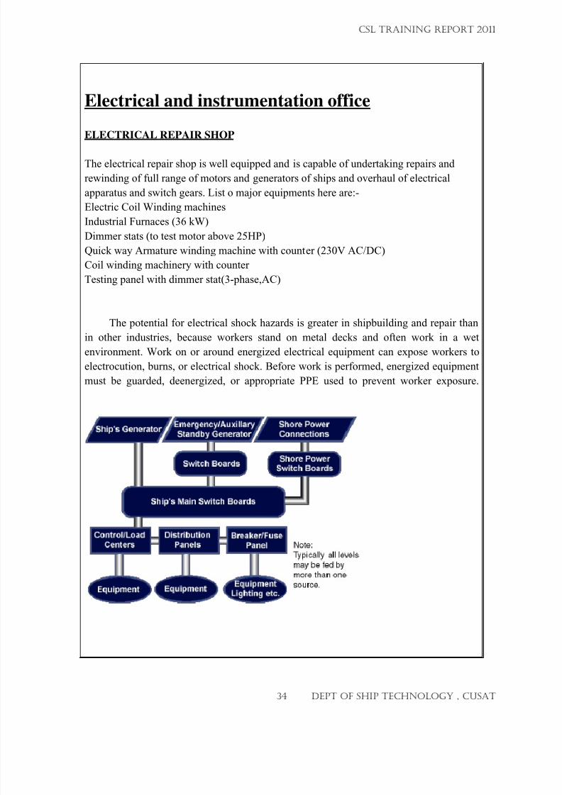
Electrical and instrumentation office
ELECTRICAL REPAIR SHOP
The electrical repair shop is well equipped and is capable of undertaking repairs and
rewinding of full range of motors and generators of ships and overhaul of electrical
apparatus and switch gears. List o major equipments here are:-
Electric Coil Winding machines
Industrial Furnaces (36 kW)
Dimmer stats (to test motor above 25HP)
Quick way Armature winding machine with counter (230V AC/DC)
Coil winding machinery with counter
Testing panel with dimmer stat(3-phase,AC)
The potential for electrical shock hazards is greater in shipbuilding and repair than
in other industries, because workers stand on metal decks and often work in a wet
environment. Work on or around energized electrical equipment can expose workers to
electrocution, burns, or electrical shock. Before work is performed, energized equipment
must be guarded, deenergized, or appropriate PPE used to prevent worker exposure.
CSL TRAINING REPORT 2011
34 DEPT OF SHIP TECHNOLOGY , CUSAT
7/23/2019 CSL FINAL_3
http://slidepdf.com/reader/full/csl-final3 35/132
1.1. Emergency Electrical Distribution System Configuration
The emergency electrical distribution systems for all vessels Groups 1 through and
including shall be considered standard as follows:
Alternating Current Systems:
3-phase, 3-wire insulated system;
single phase, 2 wired insulated system,
For Direct Current Systems, 2 wire insulated systems.
Generators
The generator is the heart of the ship. The electrical system should be characterized in
such a way that it supplies sufficient energy to all systems of the ship and for that it is
extremely essential that the correct sizing of the generators is done. The correct sizing of
the generator is the key to a safe, workable and economic electrical system. The size of
the generator depends on the load. The load often varies or undergoes swings as the
generator is connected to various other elements such as motors, heating elements and air
conditioning systems. Therefore, considerable care should be taken for generators are
susceptible to heavy system load swings.
Every ship must have at least two generators which have their individual diesel engines.
But running them through out the voyage is expensive and uneconomical as far as fuel
consumption is concerned. Thus every ship should have at least one generator that is
attached to its propulsion system.It’s always advisable that a ship should have three generators. One that is connected to its
propulsion system and the other two having their own prime movers. That way if one
fails the other two are sufficient to take the load with all the load swings.
Motor and Motor Controls
The second important thing that we will require is motors and their controls. Motors are
used onboard to run various auxiliaries such as fuel and lubrication oil services,
ventilation systems, water circulation etc. All these motors are controlled from a group
motor controller which is located at a convenient position such as a machinery control
room or in the engine room itself. The most economical way is to provide local starters
for each motor supplied from main power panels located in the same or adjacent rooms.
Nowadays most of the ships have a centralized machine control system where all the
motors are connected to a machinery control room with the help of cables which are then
connected to push button startups located on centralized machinery control console. This
is the most efficient and user friendly arrangement which is used by almost all ships .
CSL TRAINING REPORT 2011
35 DEPT OF SHIP TECHNOLOGY , CUSAT
7/23/2019 CSL FINAL_3
http://slidepdf.com/reader/full/csl-final3 36/132
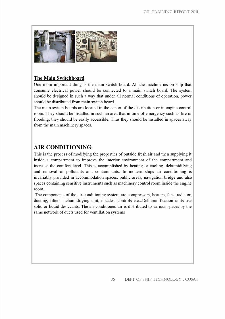
The Main Switchboard
One more important thing is the main switch board. All the machineries on ship that
consume electrical power should be connected to a main switch board. The system
should be designed in such a way that under all normal conditions of operation, power
should be distributed from main switch board.
The main switch boards are located in the center of the distribution or in engine control
room. They should be installed in such an area that in time of emergency such as fire or
flooding, they should be easily accessible. Thus they should be installed in spaces away
from the main machinery spaces.
AIR CONDITIONINGThis is the process of modifying the properties of outside fresh air and then supplying it
inside a compartment to improve the interior environment of the compartment and
increase the comfort level. This is accomplished by heating or cooling, dehumidifyingand removal of pollutants and contaminants. In modern ships air conditioning is
invariably provided in accommodation spaces, public areas, navigation bridge and also
spaces containing sensitive instruments such as machinery control room inside the engine
room.
The components of the air-conditioning system are compressors, heaters, fans, radiator,
ducting, filters, dehumidifying unit, nozzles, controls etc...Dehumidification units use
solid or liquid desiccants. The air conditioned air is distributed to various spaces by the
same network of ducts used for ventillation systems
CSL TRAINING REPORT 2011
36 DEPT OF SHIP TECHNOLOGY , CUSAT
7/23/2019 CSL FINAL_3
http://slidepdf.com/reader/full/csl-final3 37/132
Hull repair
THE WORK CARRIED OUT BY THE HULL DEPARTMENT :
Survey& Identification
Preparatory jobs
Safety precaution
Cropping
Preparation of new plate
Fit up
InspectionWelding
Dry-Survey
Inspection
NDT
Review of NDT by Class
Various surveying standards for gauging hull repair.
MMD-Mercantile marine department
ABS- American bureau of shipping
IRS- Indian Registration of shipping
Different methods used to identify the work
Visual inspection
UT GaugingOther NDT’s like MPI
CSL TRAINING REPORT 2011
37 DEPT OF SHIP TECHNOLOGY , CUSAT
7/23/2019 CSL FINAL_3
http://slidepdf.com/reader/full/csl-final3 38/132
Non-destructive test conducting in repair
Vaccum pressure test
Water pressure testingDP testing
X-RAY testing
UT gauging.
PROCEDURES FOR THE PLATE RENEWAL
1)ASSESSMENT OF DEFECTS AND PLATE CONDITIONS
Visual inspection
If surface heavily dented, pitted – plate to be changed
If the plate thickness measured by UT is less than 10-15 % of original thickness , renewal
is recommended
If internals / stiffeners have wormed out, paneling of internals recommended.
Thickness gauging of plates using Ultra sonic can be measured only to the plates 3 mm
and above.
2) FINALISATION OF WELDING PROCEDURE
3) INSPECTION OF WELD JOINT AND SUGGEST RECTIFICATION
4) PRESENTING THE JOINTS TO SURVEYOR
Different factors in new plate fit up
Follow standards such as
root gap
edge preparation
corners
scallops
CSL TRAINING REPORT 2011
38 DEPT OF SHIP TECHNOLOGY , CUSAT
7/23/2019 CSL FINAL_3
http://slidepdf.com/reader/full/csl-final3 39/132
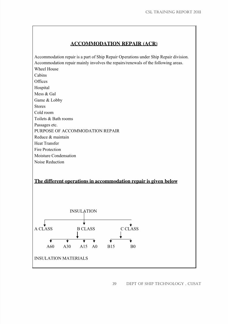
ACCOMMODATION REPAIR (ACR)
Accommodation repair is a part of Ship Repair Operations under Ship Repair division.Accommodation repair mainly involves the repairs/renewals of the following areas.
Wheel House
Cabins
Offices
Hospital
Mess & Gal
Game & Lobby
Stores
Cold roomToilets & Bath rooms
Passages etc.
PURPOSE OF ACCOMMODATION REPAIR
Reduce & maintain
Heat Transfer
Fire Protection
Moisture Condensation
Noise Reduction
The different operations in accommodation repair is given below
INSULATION
A CLASS B CLASS C CLASS
A60 A30 A15 A0 B15 B0
INSULATION MATERIALS
CSL TRAINING REPORT 2011
39 DEPT OF SHIP TECHNOLOGY , CUSAT
7/23/2019 CSL FINAL_3
http://slidepdf.com/reader/full/csl-final3 40/132
MFMB (Mineral Fiber Marine Board)
Glass wool
Rock wool
PUF (Poly Urethane Foam)
TYPES OF INSULATION
Insulation without covering.
Insulation with Chicken Mesh.
PANELING
Appearance
Finish
Cleanliness
Sound Proofing
Heat Insulation
Fire Proofing
PANELING MATERIALS
Stainless Steel
Aluminium Sheet
Melamine Faced Pre-laminated Board (Nova pan)
Marine Plywood with Sun micaMelamine Plastic Laminated Board (MPL)
Sandwich type
Paneling involves
Fixing Channels / Cleats
Wooden Frame Work
Fixing the Paneling
Filling the gaps with Beading (Aluminum / Wood)
FLOORINGMACROTECH
Surface Preparation (Fire Guard – 601)
Primer (Fire guard –P)
Underlay (MAS – 98)
Top Coat (MAS – 96)
CSL TRAINING REPORT 2011
40 DEPT OF SHIP TECHNOLOGY , CUSAT
7/23/2019 CSL FINAL_3
http://slidepdf.com/reader/full/csl-final3 41/132
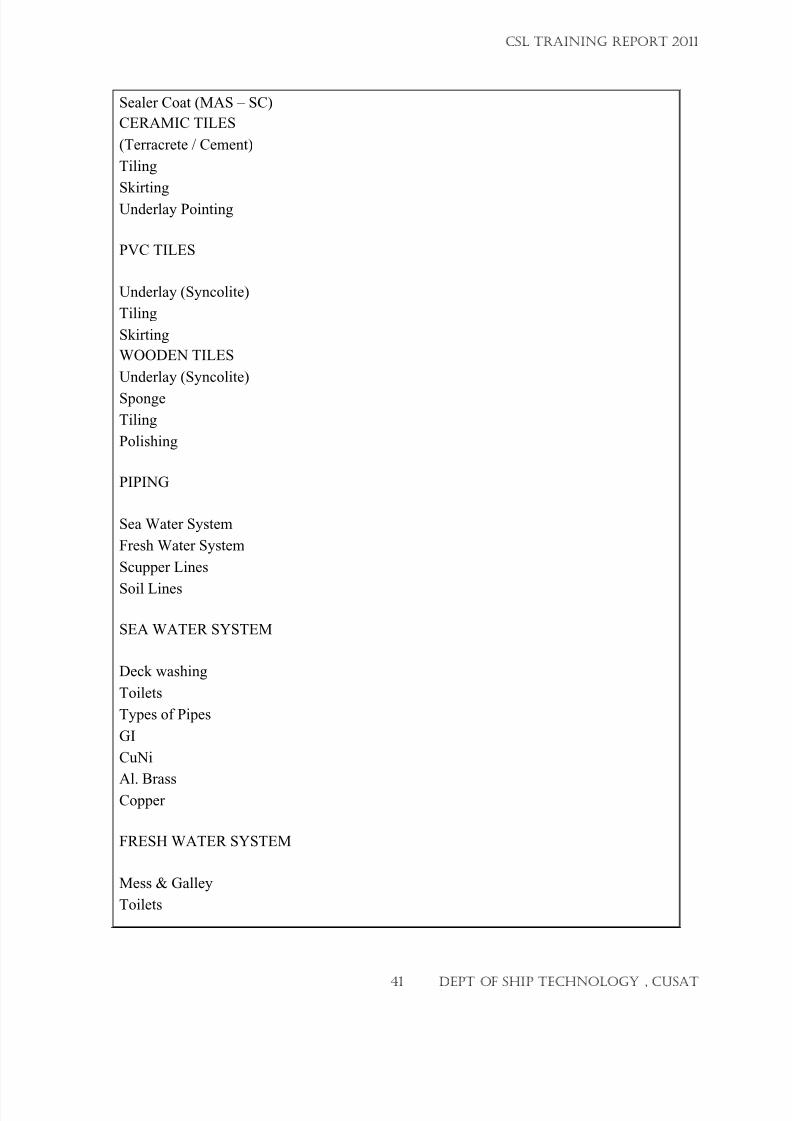
Sealer Coat (MAS – SC)
CERAMIC TILES
(Terracrete / Cement)
Tiling
Skirting
Underlay Pointing
PVC TILES
Underlay (Syncolite)
Tiling
Skirting
WOODEN TILES
Underlay (Syncolite)
Sponge
Tiling
Polishing
PIPING
Sea Water System
Fresh Water System
Scupper Lines
Soil Lines
SEA WATER SYSTEM
Deck washing
Toilets
Types of Pipes
GI
CuNi
Al. BrassCopper
FRESH WATER SYSTEM
Mess & Galley
Toilets
CSL TRAINING REPORT 2011
41 DEPT OF SHIP TECHNOLOGY , CUSAT
7/23/2019 CSL FINAL_3
http://slidepdf.com/reader/full/csl-final3 42/132
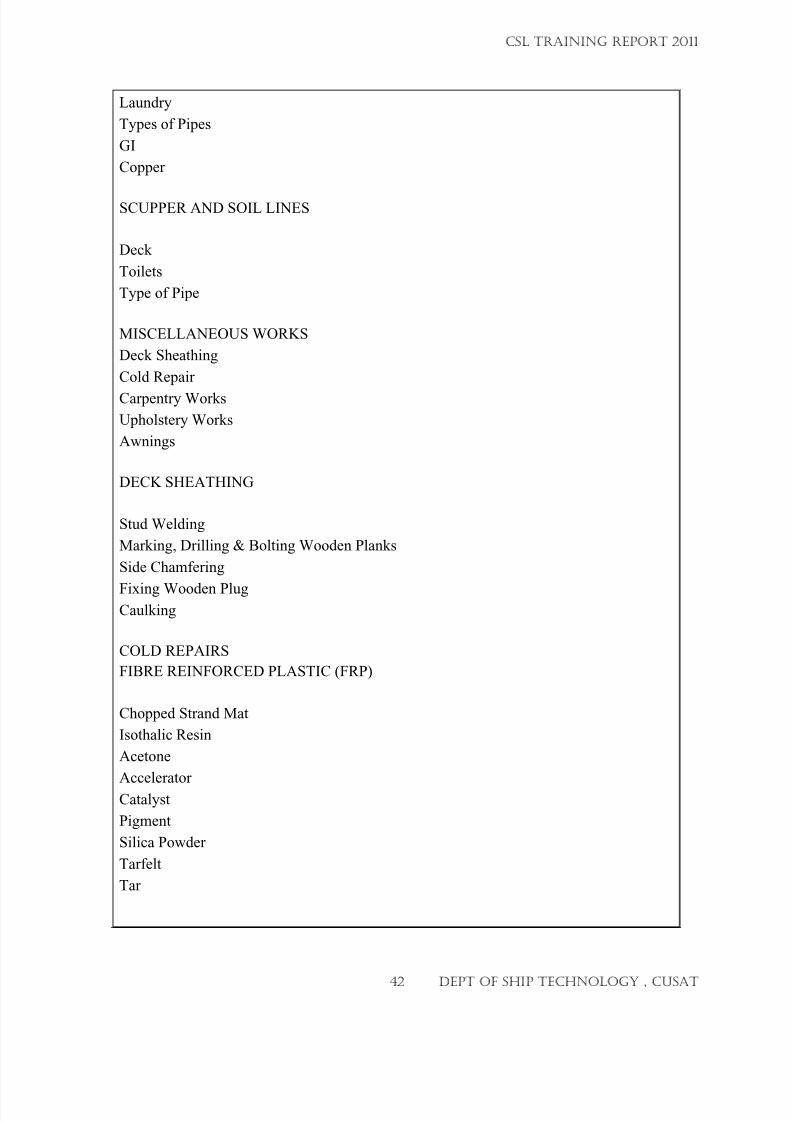
Laundry
Types of Pipes
GI
Copper
SCUPPER AND SOIL LINES
Deck
Toilets
Type of Pipe
MISCELLANEOUS WORKS
Deck Sheathing
Cold Repair
Carpentry Works
Upholstery Works
Awnings
DECK SHEATHING
Stud Welding
Marking, Drilling & Bolting Wooden Planks
Side Chamfering
Fixing Wooden PlugCaulking
COLD REPAIRS
FIBRE REINFORCED PLASTIC (FRP)
Chopped Strand Mat
Isothalic Resin
Acetone
AcceleratorCatalyst
Pigment
Silica Powder
Tarfelt
Tar
CSL TRAINING REPORT 2011
42 DEPT OF SHIP TECHNOLOGY , CUSAT
7/23/2019 CSL FINAL_3
http://slidepdf.com/reader/full/csl-final3 43/132
CARPENTARY WORKS
Wooden fenders
Boat chokes
Furniture
AWING
FRP sheet
Aluminium sheet
UPHOLSTERY WORKS
Rexin
Sponge
Canvas
Curtains
During the training period, we wear the part of team involved in the following ship’s
works
Psv series,nirikshak,AHTS,fishing vessel ,ads
CSL TRAINING REPORT 2011
43 DEPT OF SHIP TECHNOLOGY , CUSAT
7/23/2019 CSL FINAL_3
http://slidepdf.com/reader/full/csl-final3 44/132
Docking and painting
PAINTING
Paint mainly consists of a pigment dispensed in a liquid referred to as the
vehicle. The vehicle in turn consists of a binder and a solvent.
Conventional paints mainly consists of two major components are given by,
1.Pigment 2.vehicle
1.Pigment – It is a discrete particulate solid used to impart specific protective or
decorative qualities to the coating. Pigments are used to provide rust inhibitingcharacteristics, provide colour, and provide mechanical reinforcement
2.Vehicle –it is the liquid base of the coating consists of a solvent, binder and any
required liquid additives.
Type of paints
In ship building industry, different systems of paints are used in different areas
according to the purpose for which they are intended to get the decided property.
Fresh water tank paint-high build epoxy
Water ballast paint-portable water tank epoxy
Chain locker –modified epoxy
Wheelhouse inside paneling-high builds bituminous epoxy
Above water area-Two coats of modified epoxy and polyurethane paint
Under water area –Two coats of modified epoxy, vinyl modified epoxy (tie coat) and
Three coats of synthetic paint (TBT free antifouling)
Boot top area – Two glass flake epoxy, vinyl modified epoxy (tie coat) and
Three coats of synthetic paint (TBT free antifouling)Oil tanks –Modified epoxy
Visible steels –High build urethane epoxy
Engine casing –heat resistant paint
CSL TRAINING REPORT 2011
44 DEPT OF SHIP TECHNOLOGY , CUSAT
7/23/2019 CSL FINAL_3
http://slidepdf.com/reader/full/csl-final3 45/132
SURFACE PREPARATION
The surface should be well prepared in order to increase the performance
of the coating .the surface should be free from grease, oils, residues, finger prints,chemical salts, dust etc. There are different methods are used for surface preparation and
are given by,
1.Blast cleaning using short or grit
2.Acid pickling
3.Water jetting
4.Power tool cleaning
5.Hand tool cleaning
6.Solvent cleaning
1.Blast cleaning-
In blast cleaning short or grit is used which is forced under pressure to the surface to
prepare the surface for painting. Equipments used for blast cleaning are given by,
Abrasive recovery system
Blasting machine (hopper)
Blasting gun
Solenoid control system
2.Acid pickling-It is a type of chemical cleaning, sulphuric acid rinsing, hydrochloric acid rinsing,
water rinsing are done in pickling shop
3.Water jetting-
In this method high-pressure water is used and is jetted to the surface to be
cleaned, mainly used to clean the painted surface before painting the next coat.
4.Power tool cleaning-
In power tool cleaning power assisted mechanical cleaning tools are used to
prepare the steel surface for painting .the most commonly used power tools are given by,
Rotary wire brush
Chipping hammer
CSL TRAINING REPORT 2011
45 DEPT OF SHIP TECHNOLOGY , CUSAT
7/23/2019 CSL FINAL_3
http://slidepdf.com/reader/full/csl-final3 46/132
Needle scaler
Grinders and sanders
Flap wheels
5.Hand tool cleaning-
In this method non-powered hand tools are used to prepare the surface for
painting. Tools used in hand tool cleaning are given by,
Wire brushes
Scrapers
Chisels
Chipping hammers
6.Solvent cleaning-
This method is used to remove the visible oils, grease, dust, sand, and other
soluble
contaminants from steel surface.
Marine coating shop
In CSL, inside the marine coating shop, blasting is carried out and then painting
is done. Different type of machineries are used in marine coating shop to throw the girt
on to the surface in order to make SA 2.5 standard surface, equipments to control theatmospheric conditions suitable for painting and an abrasive grit recovery system. Silos
in marine coating shop have 8ton capacity, and the recovery rate of abrasive is 3.5ton to
8 ton per hour. The blasting machine is knows as macro blast machine (hopper)
integrated with pneumatic remote control system. The paint application is by air less
spray method; pneumatic piston pump is used for the same.
Standards of surface preparation
St2 surface is obtained by hand and power tool cleaningSt3 surface is obtained by very through hand and power tool cleaning
Sa1 is obtained by light blast cleaning
Sa2 is obtained by through light blast cleaning
Sa2.5 is obtained by very through light blast cleaning
Sa3 blast cleaning to visually clean steel
CSL TRAINING REPORT 2011
46 DEPT OF SHIP TECHNOLOGY , CUSAT
7/23/2019 CSL FINAL_3
http://slidepdf.com/reader/full/csl-final3 47/132
Paint System for Ships:
Bottom Surface upto Boot Top – CR Anti corrosion, CR Anti fouling.Boot Top Region – CR Anti corrosive, CR Finish.
Top Side - CR Anti corrosive, CR Finish.
Superstructure – Epoxy Primer, Alkyd Paint.
Self Polishing Co-primer (SPC)
As per this new system of painting, depending upon the duration of next dry
docking, the thickness of the film is decided and SPC is applied. Whenever a fouling
material try to stick on the hull, a layer of the paint get loose from the hull and hence act
as an anti fouling paint. This system provide a reduced frictional resistance and thus
improve speed and fuel efficiency. Moreover, hull cleaning during dry docking is easy.
Methods of Painting
1. By Brushing or Roller
2. Air Spray & Airless Spray
In Air spray, compressed air mixes with the paint and passes through an
atomizing nozzle. ( There is chances of locking air bubbles in between paint)
But in Airless Spray, compressed air is used to force the paint through an
atomizing nozzle.
Paint failuresPaint failures, which are generally seen on the painted surface are given by,
Sagging
Pealing
Pinholes
Crocodile
Blushing
Spatter seat
CSL TRAINING REPORT 2011
47 DEPT OF SHIP TECHNOLOGY , CUSAT
7/23/2019 CSL FINAL_3
http://slidepdf.com/reader/full/csl-final3 48/132
Docking
Docking is the process of entering a ship in to the dry dock , Dry-dock is anarrow basin or vessel that can be flooded to allow a load to be floated in, then drained toallow that load to come to rest on a dry platform. Dry-docks are used for the construction,
maintenance, and repair of ships, boats, and other watercraft, Special internal structure
should be provided for vessels to resist docking loads
TYPES OF DRY DOCKS
1.Continuous wing wall Floating docks
2.Slipway3.Sectional floating dry-docks
4.Marine elevator dry-dock
5.Graving dock
We saw graving dock in CSL . the properties of graving dock is The
classic form of dry-dock, properly known as graving dock, is a narrow basin, usually
made of earthen beams and concrete, closed by gates or by a caisson, into which a vesselmay be floated and the water pumped out, leaving the vessel supported on blocks. The
keel blocks as well as the bilge block are placed on the floor of the dock in accordance
with the "docking plan" of the ship
Docking requirements are listed below :
• Docking Plan
• Block setting & Marking
• Flooding
• Tugs & Boats
• Mooring crew
• Cranes on both sides
•
Capstons• Winches
• Hauling Carriage
• Reference lines, Mouse & Ropes
CSL TRAINING REPORT 2011
48 DEPT OF SHIP TECHNOLOGY , CUSAT
7/23/2019 CSL FINAL_3
http://slidepdf.com/reader/full/csl-final3 49/132
Docking Procedure :
Docking process is controlled by Dock Master, Controlling Officer, Supervisors and team
leaders.
1.For docking a ship, leader with mooring crews take position to the FWD & AFT of
the ship before entering to the dock.
2.Pass the heaving line to the boat for taking FWD winch lines or dock lines according
to the direction of the leader.
3. Connect the steel rope on ships bollard.
4. At the same time one ship line will pass through the boats to the jetty for connecting
to hauling carriage.
5. Shackle this headline rope ends to the hauling carriage hook which is fitted to the siderails of the dock.
6. Two tugs from Port & Stbd pushes the ship to keep center position.
7. As soon as the bow enters the dock, put another nylon rope (spring rope) for holding
the speed of the ship, when head line rope pulling proceeds.
8. Immediately after stern enters the dock, capstone ropes will pass to the AFT of the
vessel with both cranes.
9. Use mouse method or bow line method for accurate seating.
Undocking procedure :
For undocking also the above mentioned officers and team are required.
Before flooding, all ropes (Head ,Spring, Breast, Stern) are provided on both stbd & port
sides.
A steel rope from ship bollard is connected with the hauling carriage on both stbd & port
side to control fwd movement (assume Aft near to dock gate).
On the other hand the hauling carriage is connected with FWD winch for its forward
movement.While running hauling carriage, aft of the vessel comes to dock mouth.
While aft comes near dock mouth nylon ropes are passed to tugs for controlling aft
movement.
When the vessel fwd comes out of dock mouth the hauling carriage ropes are detached
and the tugs control further vessel movement.
CSL TRAINING REPORT 2011
49 DEPT OF SHIP TECHNOLOGY , CUSAT
7/23/2019 CSL FINAL_3
http://slidepdf.com/reader/full/csl-final3 50/132
DOCKING SURVEY
Items to be surveyed during Dry docking:
Anodes, Paint works, Shell Plating, Stern Frame, Rudder, Propeller (Rope Guard), Sea
Chests, Bilge Keel, Anchor and Chain, Propeller Shaft (Tail Shaft), Worn out areas.
Docking Survey is conducted when the ship is docked in the drydock:
• Underwater hull inspection for any dent, crack or such damage by the Surveyor
• Ultrasonic Thickness gauging and the reports to be submitted to the Surveyor.
Steel renewals, if any to be done as directed by him.
• Anchor Chain ranging and calibration reports to be submitted.
• Inspection of Propeller, cone, nut etc by Surveyor.
• Tail shaft survey to be conducted.
• Physical inspection of Rudder, swing Test and pressure test to be arranged.
• Sea suction and Overboard discharge valve to be presented for survey.
• Inspection of Bottom Plugs for leakages.
Machinery Repairing procedures
1.
Engine room machinery2. Deck machinery
3. Pump machinery
Engine room machinery
• Main engines
• Auxiliary engine
• Boiler
• Turbine
•
Pumps
• Water makers
• Heat exchangers
• Pollution control equipments
• Tail shaft
• Propellers and thrusters
CSL TRAINING REPORT 2011
50 DEPT OF SHIP TECHNOLOGY , CUSAT
7/23/2019 CSL FINAL_3
http://slidepdf.com/reader/full/csl-final3 51/132
Overhauling of main/aux engines
• Decarbonising
• Remove cylinder head
• Remove pistons
•
Remove liner
• Cleaning
• Calibration
• Inspection and survey
• Remove bearings
• Clean and calibration
Fit back of fixed pitch propeller
• Manual push up
•
Hydraulic propellers
• Pilgrim nut
•
Fit back of controllable pitch propeller
• Renewal of blade seats
• Refitting of blades
• Refitting of hubs
• Filling oil
Tail shaft• Removal of tail shaft
• Removal of propeller
• Remove FWD and AFT seals
• Remove intermediate shaft and fitted bolts
• Lower internal shaft
• Clean and calibrate tail shaft and stress tube bushes
• Present for survey
• Renew stress tube bushes and shaft seals as required
Non destructive test conducting in repair
• Vacuum pressure test
• Water pressure test
• DP testing
• UT gauging
CSL TRAINING REPORT 2011
51 DEPT OF SHIP TECHNOLOGY , CUSAT
7/23/2019 CSL FINAL_3
http://slidepdf.com/reader/full/csl-final3 52/132
Main pumping system used in ship
• Piping
• Sea water system
• Jacket water system
• Lube oil system
• Fuel oil system
• Compressed air system
Valves
• Globe valve
• Gate valve
• Butterfly valve
•
Piston valve
Pumping
• Centrifugal pump
• Reciprocating pump
• Vane pump
• Gear pump
• Screw pump
• Diaphragm pump
Air compressors
•
Reciprocating• Rotary
• screw
CSL TRAINING REPORT 2011
52 DEPT OF SHIP TECHNOLOGY , CUSAT
7/23/2019 CSL FINAL_3
http://slidepdf.com/reader/full/csl-final3 53/132
SHIP BUILDING DEPARTMENT
(23/5/2011 to 31/5/2011)
CSL TRAINING REPORT 2011
53 DEPT OF SHIP TECHNOLOGY , CUSAT
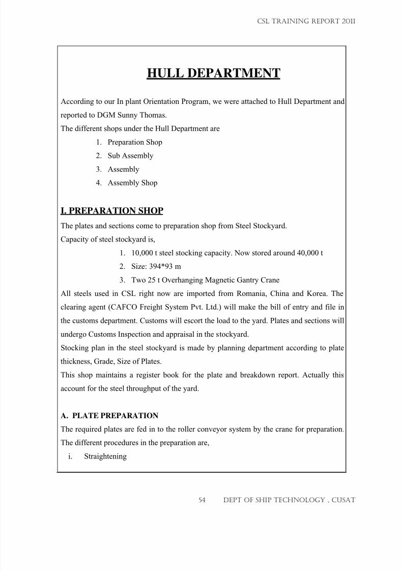
7/23/2019 CSL FINAL_3
http://slidepdf.com/reader/full/csl-final3 54/132
HULL DEPARTMENT
According to our In plant Orientation Program, we were attached to Hull Department and
reported to DGM Sunny Thomas.
The different shops under the Hull Department are
1. Preparation Shop
2. Sub Assembly
3. Assembly
4. Assembly Shop
I. PREPARATION SHOP
The plates and sections come to preparation shop from Steel Stockyard.
Capacity of steel stockyard is,
1. 10,000 t steel stocking capacity. Now stored around 40,000 t
2. Size: 394*93 m
3. Two 25 t Overhanging Magnetic Gantry Crane
All steels used in CSL right now are imported from Romania, China and Korea. The
clearing agent (CAFCO Freight System Pvt. Ltd.) will make the bill of entry and file in
the customs department. Customs will escort the load to the yard. Plates and sections will
undergo Customs Inspection and appraisal in the stockyard.
Stocking plan in the steel stockyard is made by planning department according to plate
thickness, Grade, Size of Plates.
This shop maintains a register book for the plate and breakdown report. Actually this
account for the steel throughput of the yard.
A. PLATE PREPARATION
The required plates are fed in to the roller conveyor system by the crane for preparation.
The different procedures in the preparation are,
i. Straightening
CSL TRAINING REPORT 2011
54 DEPT OF SHIP TECHNOLOGY , CUSAT
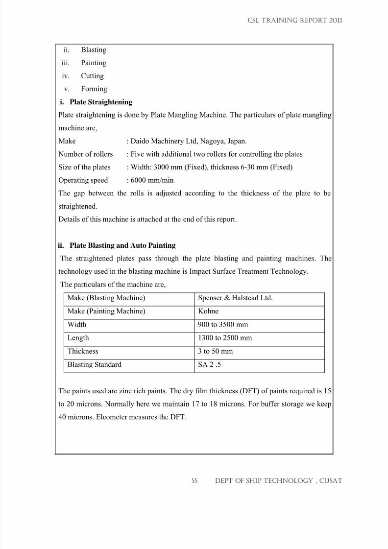
7/23/2019 CSL FINAL_3
http://slidepdf.com/reader/full/csl-final3 55/132
ii. Blasting
iii. Painting
iv. Cutting
v. Forming
i. Plate Straightening
Plate straightening is done by Plate Mangling Machine. The particulars of plate mangling
machine are,
Make : Daido Machinery Ltd, Nagoya, Japan.
Number of rollers : Five with additional two rollers for controlling the plates
Size of the plates : Width: 3000 mm (Fixed), thickness 6-30 mm (Fixed)
Operating speed : 6000 mm/min
The gap between the rolls is adjusted according to the thickness of the plate to be
straightened.
Details of this machine is attached at the end of this report.
ii. Plate Blasting and Auto Painting
The straightened plates pass through the plate blasting and painting machines. The
technology used in the blasting machine is Impact Surface Treatment Technology.
The particulars of the machine are,
Make (Blasting Machine) Spenser & Halstead Ltd.
Make (Painting Machine) Kohne
Width 900 to 3500 mm
Length 1300 to 2500 mm
Thickness 3 to 50 mm
Blasting Standard SA 2 .5
The paints used are zinc rich paints. The dry film thickness (DFT) of paints required is 15
to 20 microns. Normally here we maintain 17 to 18 microns. For buffer storage we keep
40 microns. Elcometer measures the DFT.
CSL TRAINING REPORT 2011
55 DEPT OF SHIP TECHNOLOGY , CUSAT
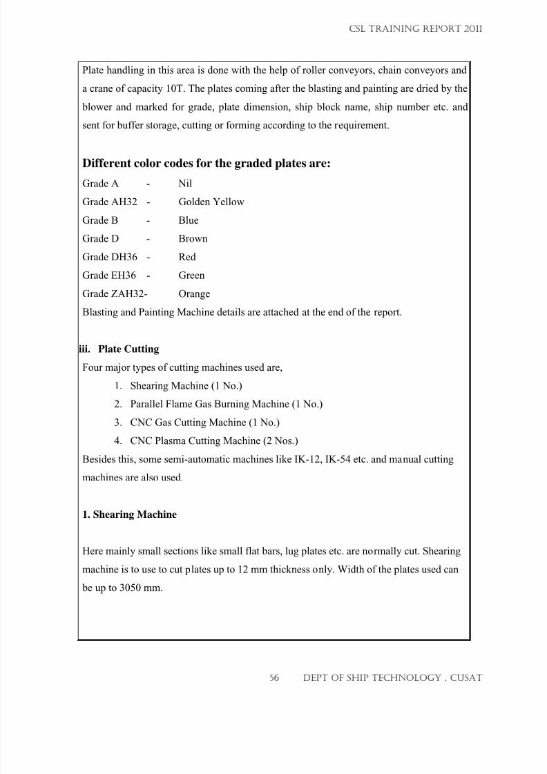
7/23/2019 CSL FINAL_3
http://slidepdf.com/reader/full/csl-final3 56/132
Plate handling in this area is done with the help of roller conveyors, chain conveyors and
a crane of capacity 10T. The plates coming after the blasting and painting are dried by the
blower and marked for grade, plate dimension, ship block name, ship number etc. and
sent for buffer storage, cutting or forming according to the requirement.
Different color codes for the graded plates are:
Grade A - Nil
Grade AH32 - Golden Yellow
Grade B - Blue
Grade D - Brown
Grade DH36 - Red
Grade EH36 - Green
Grade ZAH32- Orange
Blasting and Painting Machine details are attached at the end of the report.
iii. Plate Cutting
Four major types of cutting machines used are,
1. Shearing Machine (1 No.)
2.
Parallel Flame Gas Burning Machine (1 No.)3. CNC Gas Cutting Machine (1 No.)
4. CNC Plasma Cutting Machine (2 Nos.)
Besides this, some semi-automatic machines like IK-12, IK-54 etc. and manual cutting
machines are also used.
1. Shearing Machine
Here mainly small sections like small flat bars, lug plates etc. are normally cut. Shearing
machine is to use to cut plates up to 12 mm thickness only. Width of the plates used can
be up to 3050 mm.
CSL TRAINING REPORT 2011
56 DEPT OF SHIP TECHNOLOGY , CUSAT
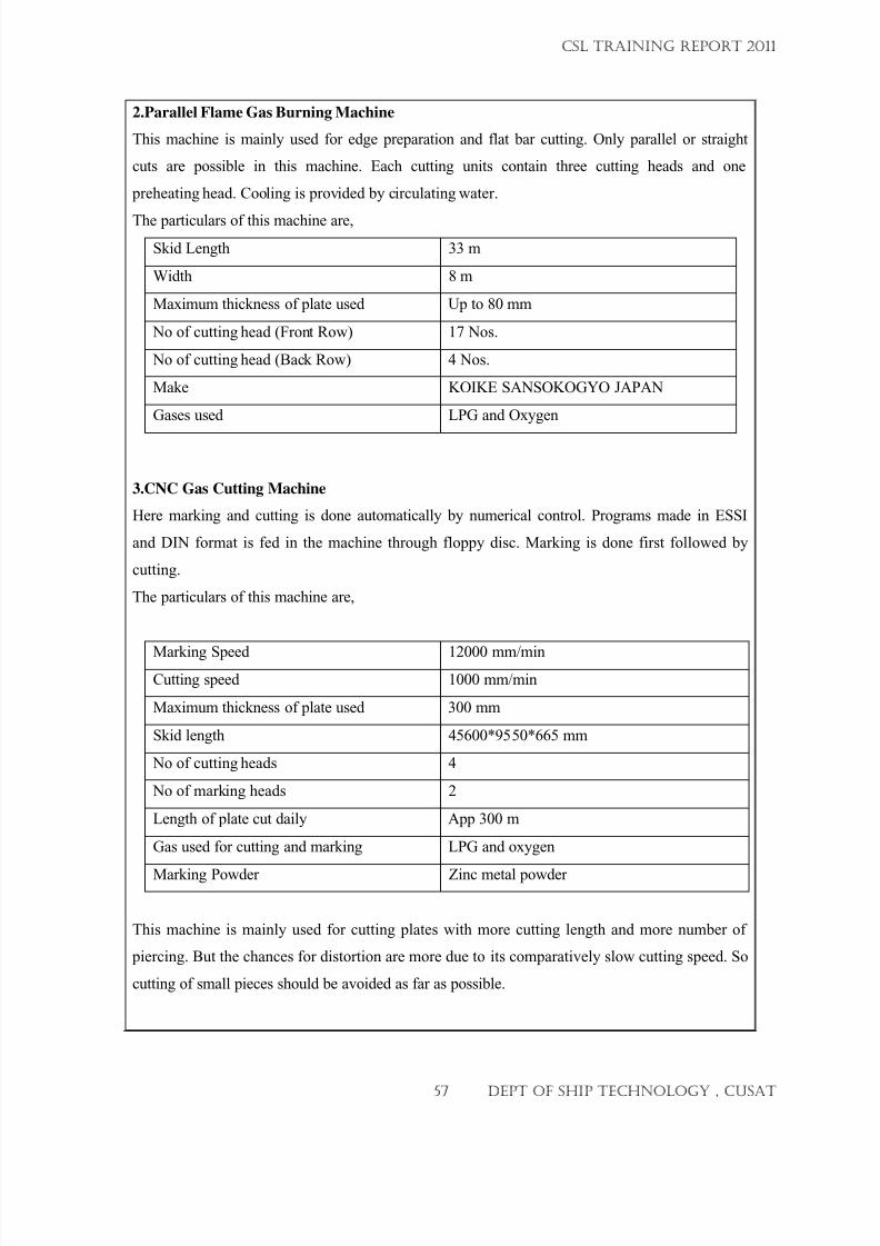
7/23/2019 CSL FINAL_3
http://slidepdf.com/reader/full/csl-final3 57/132
2.Parallel Flame Gas Burning Machine
This machine is mainly used for edge preparation and flat bar cutting. Only parallel or straight
cuts are possible in this machine. Each cutting units contain three cutting heads and one
preheating head. Cooling is provided by circulating water.
The particulars of this machine are,
Skid Length 33 m
Width 8 m
Maximum thickness of plate used Up to 80 mm
No of cutting head (Front Row) 17 Nos.
No of cutting head (Back Row) 4 Nos.
Make KOIKE SANSOKOGYO JAPAN
Gases used LPG and Oxygen
3.CNC Gas Cutting Machine
Here marking and cutting is done automatically by numerical control. Programs made in ESSI
and DIN format is fed in the machine through floppy disc. Marking is done first followed by
cutting.
The particulars of this machine are,
Marking Speed 12000 mm/min
Cutting speed 1000 mm/min
Maximum thickness of plate used 300 mm
Skid length 45600*9550*665 mm
No of cutting heads 4
No of marking heads 2
Length of plate cut daily App 300 m
Gas used for cutting and marking LPG and oxygen
Marking Powder Zinc metal powder
This machine is mainly used for cutting plates with more cutting length and more number of
piercing. But the chances for distortion are more due to its comparatively slow cutting speed. So
cutting of small pieces should be avoided as far as possible.
CSL TRAINING REPORT 2011
57 DEPT OF SHIP TECHNOLOGY , CUSAT
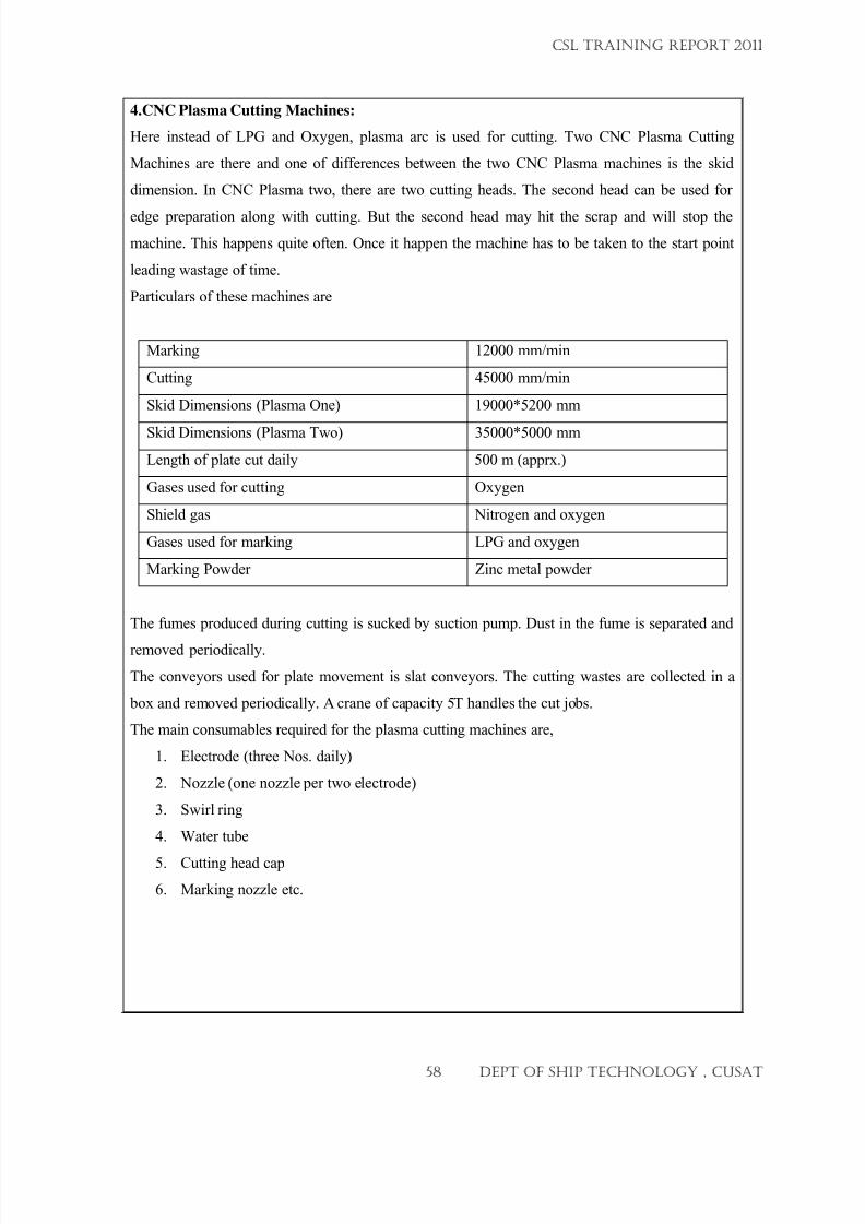
7/23/2019 CSL FINAL_3
http://slidepdf.com/reader/full/csl-final3 58/132
4.CNC Plasma Cutting Machines:
Here instead of LPG and Oxygen, plasma arc is used for cutting. Two CNC Plasma Cutting
Machines are there and one of differences between the two CNC Plasma machines is the skid
dimension. In CNC Plasma two, there are two cutting heads. The second head can be used for
edge preparation along with cutting. But the second head may hit the scrap and will stop the
machine. This happens quite often. Once it happen the machine has to be taken to the start point
leading wastage of time.
Particulars of these machines are
Marking 12000 mm/min
Cutting 45000 mm/min
Skid Dimensions (Plasma One) 19000*5200 mm
Skid Dimensions (Plasma Two) 35000*5000 mm
Length of plate cut daily 500 m (apprx.)
Gases used for cutting Oxygen
Shield gas Nitrogen and oxygen
Gases used for marking LPG and oxygen
Marking Powder Zinc metal powder
The fumes produced during cutting is sucked by suction pump. Dust in the fume is separated and
removed periodically.
The conveyors used for plate movement is slat conveyors. The cutting wastes are collected in a
box and removed periodically. A crane of capacity 5T handles the cut jobs.
The main consumables required for the plasma cutting machines are,
1. Electrode (three Nos. daily)
2. Nozzle (one nozzle per two electrode)
3. Swirl ring
4. Water tube
5.
Cutting head cap
6.
Marking nozzle etc.
CSL TRAINING REPORT 2011
58 DEPT OF SHIP TECHNOLOGY , CUSAT
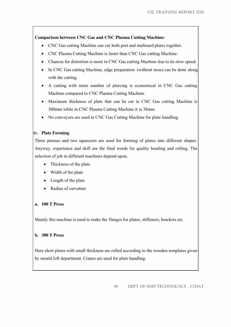
7/23/2019 CSL FINAL_3
http://slidepdf.com/reader/full/csl-final3 59/132
Comparison between CNC Gas and CNC Plasma Cutting Machine:
• CNC Gas cutting Machine can cut both port and starboard plates together.
• CNC Plasma Cutting Machine is faster than CNC Gas cutting Machine.
• Chances for distortion is more in CNC Gas cutting Machine due to its slow speed.
• In CNC Gas cutting Machine, edge preparation (without nose) can be done along
with the cutting.
• A cutting with more number of piercing is economical in CNC Gas cutting
Machine compared to CNC Plasma Cutting Machine.
• Maximum thickness of plate that can be cut in CNC Gas cutting Machine is
300mm while in CNC Plasma Cutting Machine it is 38mm.
•
No conveyors are used in CNC Gas Cutting Machine for plate handling.
iv. Plate Forming
Three presses and two squeezers are used for forming of plates into different shapes.
Anyway, experience and skill are the final words for quality bending and rolling. The
selection of job in different machines depend upon,
• Thickness of the plate
•
Width of the plate
• Length of the plate
• Radius of curvature
a. 100 T Press
Mainly this machine is used to make the flanges for plates, stiffeners, brackets etc.
b. 300 T Press
Here short plates with small thickness are rolled according to the wooden templates given
by mould loft department. Cranes are used for plate handling.
CSL TRAINING REPORT 2011
59 DEPT OF SHIP TECHNOLOGY , CUSAT
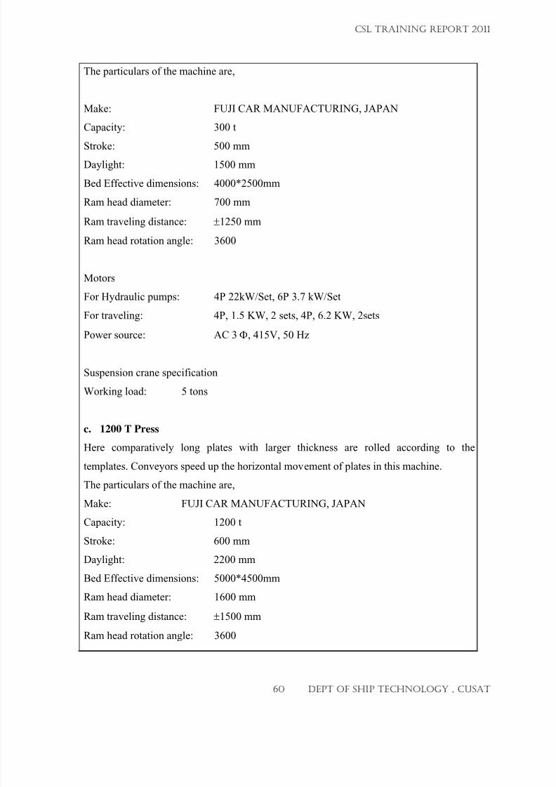
7/23/2019 CSL FINAL_3
http://slidepdf.com/reader/full/csl-final3 60/132
The particulars of the machine are,
Make: FUJI CAR MANUFACTURING, JAPAN
Capacity: 300 t
Stroke: 500 mm
Daylight: 1500 mm
Bed Effective dimensions: 4000*2500mm
Ram head diameter: 700 mm
Ram traveling distance: ±1250 mm
Ram head rotation angle: 3600
Motors
For Hydraulic pumps: 4P 22kW/Set, 6P 3.7 kW/Set
For traveling: 4P, 1.5 KW, 2 sets, 4P, 6.2 KW, 2sets
Power source: AC 3 Φ, 415V, 50 Hz
Suspension crane specification
Working load: 5 tons
c. 1200 T Press
Here comparatively long plates with larger thickness are rolled according to the
templates. Conveyors speed up the horizontal movement of plates in this machine.
The particulars of the machine are,
Make: FUJI CAR MANUFACTURING, JAPAN
Capacity: 1200 t
Stroke: 600 mm
Daylight: 2200 mm
Bed Effective dimensions: 5000*4500mm
Ram head diameter: 1600 mm
Ram traveling distance: ±1500 mm
Ram head rotation angle: 3600
CSL TRAINING REPORT 2011
60 DEPT OF SHIP TECHNOLOGY , CUSAT
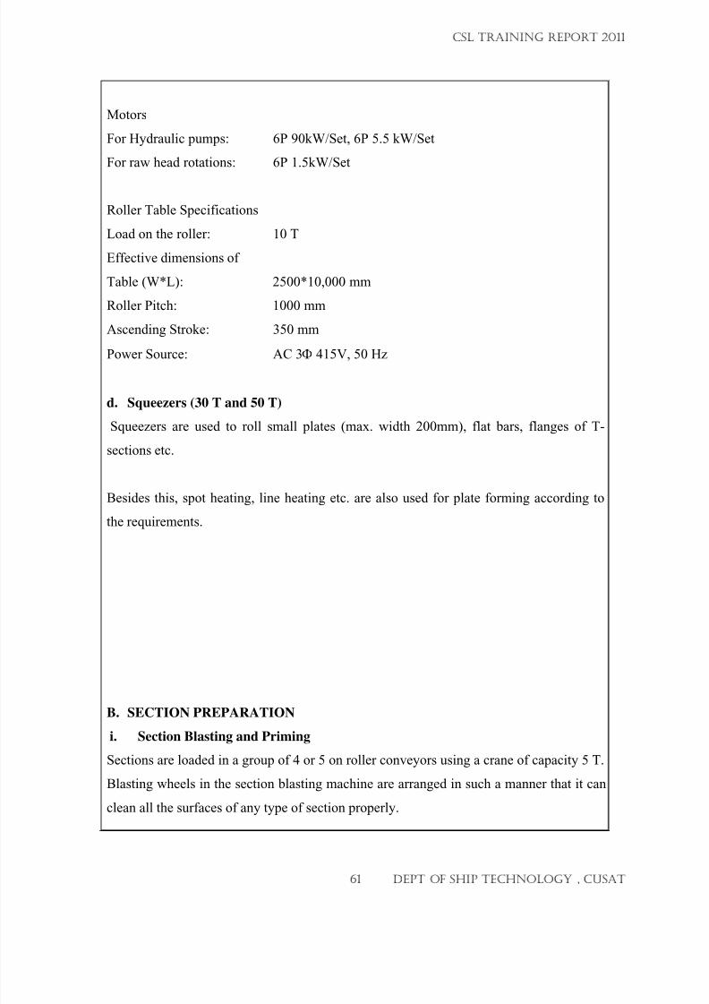
7/23/2019 CSL FINAL_3
http://slidepdf.com/reader/full/csl-final3 61/132
Motors
For Hydraulic pumps: 6P 90kW/Set, 6P 5.5 kW/Set
For raw head rotations: 6P 1.5kW/Set
Roller Table Specifications
Load on the roller: 10 T
Effective dimensions of
Table (W*L): 2500*10,000 mm
Roller Pitch: 1000 mm
Ascending Stroke: 350 mm
Power Source: AC 3Φ 415V, 50 Hz
d. Squeezers (30 T and 50 T)
Squeezers are used to roll small plates (max. width 200mm), flat bars, flanges of T-
sections etc.
Besides this, spot heating, line heating etc. are also used for plate forming according to
the requirements.
B.
SECTION PREPARATION
i. Section Blasting and Priming
Sections are loaded in a group of 4 or 5 on roller conveyors using a crane of capacity 5 T.
Blasting wheels in the section blasting machine are arranged in such a manner that it can
clean all the surfaces of any type of section properly.
CSL TRAINING REPORT 2011
61 DEPT OF SHIP TECHNOLOGY , CUSAT
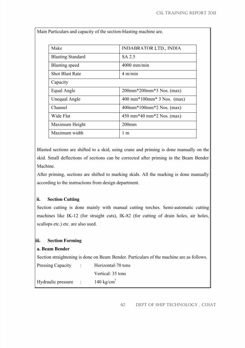
7/23/2019 CSL FINAL_3
http://slidepdf.com/reader/full/csl-final3 62/132
Main Particulars and capacity of the section-blasting machine are,
Make INDABRATOR LTD., INDIA
Blasting Standard SA 2.5
Blasting speed 4000 mm/min
Shot Blast Rate 4 m/min
Capacity
Equal Angle 200mm*200mm*3 Nos. (max)
Unequal Angle 400 mm*100mm* 3 Nos. (max)
Channel 400mm*100mm*2 Nos. (max)
Wide Flat 450 mm*40 mm*2 Nos. (max)
Maximum Height 200mm
Maximum width 1 m
Blasted sections are shifted to a skid, using crane and priming is done manually on the
skid. Small deflections of sections can be corrected after priming in the Beam Bender
Machine.
After priming, sections are shifted to marking skids. All the marking is done manually
according to the instructions from design department.
ii. Section Cutting
Section cutting is done mainly with manual cutting torches. Semi-automatic cutting
machines like IK-12 (for straight cuts), IK-82 (for cutting of drain holes, air holes,
scallops etc.) etc. are also used.
iii. Section Forming
a. Beam Bender
Section straightening is done on Beam Bender. Particulars of the machine are as follows.
Pressing Capacity : Horizontal-70 tons
Vertical: 35 tons
Hydraulic pressure : 140 kg/cm2
CSL TRAINING REPORT 2011
62 DEPT OF SHIP TECHNOLOGY , CUSAT
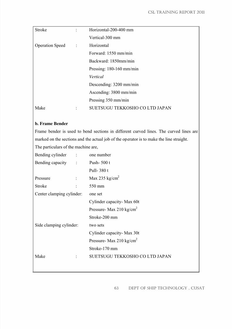
7/23/2019 CSL FINAL_3
http://slidepdf.com/reader/full/csl-final3 63/132
Stroke : Horizontal-200-400 mm
Vertical-300 mm
Operation Speed : Horizontal
Forward: 1550 mm/min
Backward: 1850mm/min
Pressing: 180-160 mm/min
Vertical
Descending: 3200 mm/min
Ascending: 3800 mm/min
Pressing 350 mm/min
Make : SUETSUGU TEKKOSHO CO LTD JAPAN
b. Frame Bender
Frame bender is used to bend sections in different curved lines. The curved lines are
marked on the sections and the actual job of the operator is to make the line straight.
The particulars of the machine are,
Bending cylinder : one number
Bending capacity : Push- 500 t
Pull- 380 t
Pressure : Max 235 kg/cm2
Stroke : 550 mm
Center clamping cylinder: one set
Cylinder capacity- Max 60t
Pressure- Max 210 kg/cm2
Stroke-200 mm
Side clamping cylinder: two sets
Cylinder capacity- Max 30t
Pressure- Max 210 kg/cm2
Stroke-170 mm
Make : SUETSUGU TEKKOSHO CO LTD JAPAN
CSL TRAINING REPORT 2011
63 DEPT OF SHIP TECHNOLOGY , CUSAT
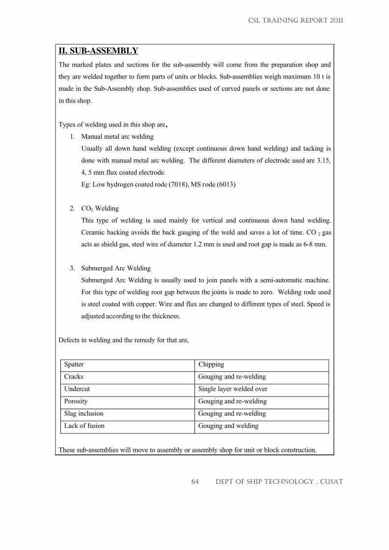
7/23/2019 CSL FINAL_3
http://slidepdf.com/reader/full/csl-final3 64/132
II. SUB-ASSEMBLY
The marked plates and sections for the sub-assembly will come from the preparation shop and
they are welded together to form parts of units or blocks. Sub-assemblies weigh maximum 10 t is
made in the Sub-Assembly shop. Sub-assemblies used of curved panels or sections are not done
in this shop.
Types of welding used in this shop are,
1. Manual metal arc welding
Usually all down hand welding (except continuous down hand welding) and tacking is
done with manual metal arc welding. The different diameters of electrode used are 3.15,
4, 5 mm flux coated electrode.
Eg: Low hydrogen coated rode (7018), MS rode (6013)
2. CO2 Welding
This type of welding is used mainly for vertical and continuous down hand welding.
Ceramic backing avoids the back gauging of the weld and saves a lot of time. CO 2 gas
acts as shield gas, steel wire of diameter 1.2 mm is used and root gap is made as 6-8 mm.
3. Submerged Arc Welding
Submerged Arc Welding is usually used to join panels with a semi-automatic machine.
For this type of welding root gap between the joints is made to zero. Welding rode used
is steel coated with copper. Wire and flux are changed to different types of steel. Speed is
adjusted according to the thickness.
Defects in welding and the remedy for that are,
Spatter Chipping
Cracks Gouging and re-welding
Undercut Single layer welded over
Porosity Gouging and re-welding
Slag inclusion Gouging and re-welding
Lack of fusion Gouging and welding
These sub-assemblies will move to assembly or assembly shop for unit or block construction.
CSL TRAINING REPORT 2011
64 DEPT OF SHIP TECHNOLOGY , CUSAT
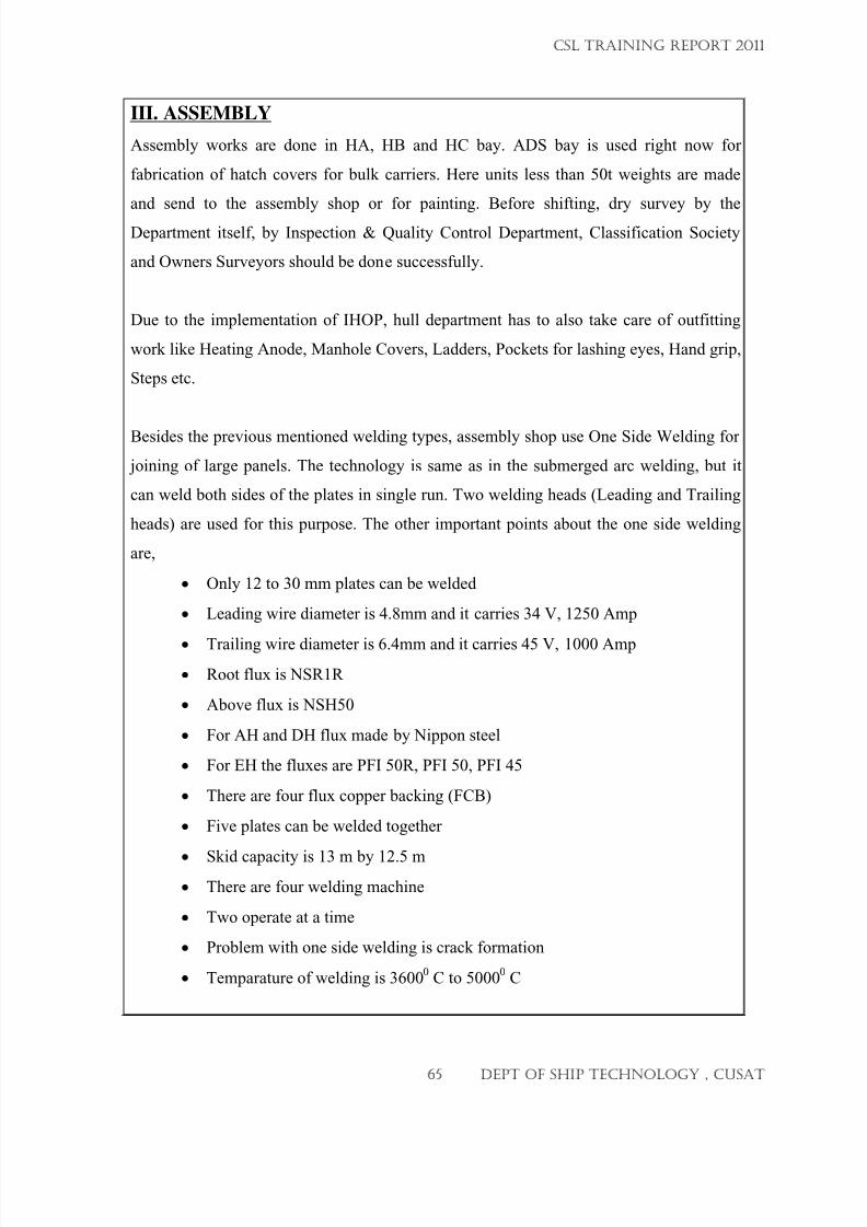
7/23/2019 CSL FINAL_3
http://slidepdf.com/reader/full/csl-final3 65/132
III. ASSEMBLY
Assembly works are done in HA, HB and HC bay. ADS bay is used right now for
fabrication of hatch covers for bulk carriers. Here units less than 50t weights are made
and send to the assembly shop or for painting. Before shifting, dry survey by the
Department itself, by Inspection & Quality Control Department, Classification Society
and Owners Surveyors should be done successfully.
Due to the implementation of IHOP, hull department has to also take care of outfitting
work like Heating Anode, Manhole Covers, Ladders, Pockets for lashing eyes, Hand grip,
Steps etc.
Besides the previous mentioned welding types, assembly shop use One Side Welding for
joining of large panels. The technology is same as in the submerged arc welding, but it
can weld both sides of the plates in single run. Two welding heads (Leading and Trailing
heads) are used for this purpose. The other important points about the one side welding
are,
• Only 12 to 30 mm plates can be welded
• Leading wire diameter is 4.8mm and it carries 34 V, 1250 Amp
•
Trailing wire diameter is 6.4mm and it carries 45 V, 1000 Amp
• Root flux is NSR1R
• Above flux is NSH50
• For AH and DH flux made by Nippon steel
• For EH the fluxes are PFI 50R, PFI 50, PFI 45
• There are four flux copper backing (FCB)
• Five plates can be welded together
•
Skid capacity is 13 m by 12.5 m
• There are four welding machine
• Two operate at a time
• Problem with one side welding is crack formation
• Temparature of welding is 3600
0 C to 5000
0 C
CSL TRAINING REPORT 2011
65 DEPT OF SHIP TECHNOLOGY , CUSAT
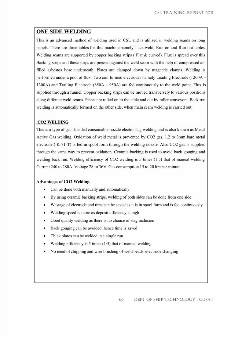
7/23/2019 CSL FINAL_3
http://slidepdf.com/reader/full/csl-final3 66/132
ONE SIDE WELDING
This is an advanced method of welding used in CSL and is utilized in welding seams on long
panels. There are three tables for this machine namely Tack weld, Run on and Run out tables.
Welding seams are supported by copper backing strips ( Flat & curved). Flux is spread over this
Backing strips and these strips are pressed against the weld seam with the help of compressed air
filled asbestos hose underneath. Plates are clamped down by magnetic clamps. Welding is
performed under a pool of flux. Two coil formed electrodes namely Leading Electrode (1200A –
1300A) and Trailing Electrode (850A – 950A) are fed continuously to the weld point. Flux is
supplied through a funnel. Copper backing strips can be moved transversely to various positions
along different weld seams. Plates are rolled on to the table and out by roller conveyors. Back run
welding is automatically formed on the other side, when main seam welding is carried out.
CO2 WELDING
This is a type of gas shielded consumable nozzle electro slag welding and is also known as Metal
Active Gas welding. Oxidation of weld metal is prevented by CO2 gas. 1.2 to 3mm bare metal
electrode ( K-71-T) is fed in spool form through the welding nozzle. Also CO2 gas is supplied
through the same way to prevent oxidation. Ceramic backing is used to avoid back gouging and
welding back run. Welding efficiency of CO2 welding is 5 times (1:5) that of manual welding.
Current 240 to 280A. Voltage 28 to 36V. Gas consumption 15 to 20 ltrs per minute.
Advantages of CO2 Welding.
• Can be done both manually and automatically
• By using ceramic backing strips, welding of both sides can be done from one side
• Wastage of electrode and time can be saved as it is in spool form and is fed continuously
• Welding speed is more as deposit efficiency is high
• Good quality welding as there is no chance of slag inclusion
• Back gouging can be avoided, hence time is saved
• Thick plates can be welded in a single run
• Welding efficiency is 5 times (1:5) that of manual welding
• No need of chipping and wire brushing of weld beads, electrode changing
CSL TRAINING REPORT 2011
66 DEPT OF SHIP TECHNOLOGY , CUSAT
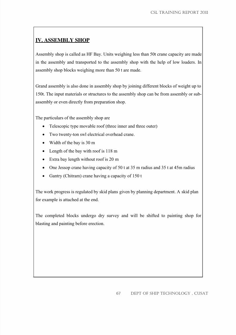
7/23/2019 CSL FINAL_3
http://slidepdf.com/reader/full/csl-final3 67/132
IV. ASSEMBLY SHOP
Assembly shop is called as HF Bay. Units weighing less than 50t crane capacity are made
in the assembly and transported to the assembly shop with the help of low loaders. In
assembly shop blocks weighing more than 50 t are made.
Grand assembly is also done in assembly shop by joining different blocks of weight up to
150t. The input materials or structures to the assembly shop can be from assembly or sub-
assembly or even directly from preparation shop.
The particulars of the assembly shop are
• Telescopic type movable roof (three inner and three outer)
• Two twenty-ton swl electrical overhead crane.
• Width of the bay is 30 m
• Length of the bay with roof is 118 m
• Extra bay length without roof is 20 m
• One Jessop crane having capacity of 50 t at 35 m radius and 35 t at 45m radius
•
Gantry (Chitram) crane having a capacity of 150 t
The work progress is regulated by skid plans given by planning department. A skid plan
for example is attached at the end.
The completed blocks undergo dry survey and will be shifted to painting shop for
blasting and painting before erection.
CSL TRAINING REPORT 2011
67 DEPT OF SHIP TECHNOLOGY , CUSAT
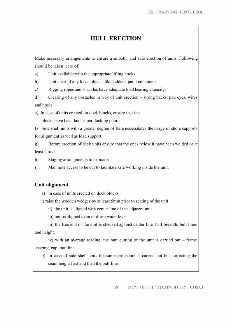
7/23/2019 CSL FINAL_3
http://slidepdf.com/reader/full/csl-final3 68/132
HULL ERECTION
Make necessary arrangements to ensure a smooth and safe erection of units. Following
should be taken care of:
a) Unit available with the appropriate lifting hooks
b) Unit clear of any loose objects like ladders, paint containers
c) Rigging ropes and shackles have adequate load bearing capacity.
d) Clearing of any obstacles in way of unit erection – strong backs, pad eyes, wires
and hoses
e) In case of units erected on dock blocks, ensure that the blocks have been laid as per docking plan.
f) Side shell units with a greater degree of flare necessitates the usage of shore supports
for alignment as well as load support.
g) Before erection of deck units ensure that the ones below it have been welded or at
least faired
h) Staging arrangements to be made
i) Man hole access to be cut to facilitate safe working inside the unit.
Unit alignment
a) In case of units erected on dock blocks:
i) raise the wooden wedges by at least 5mm prior to seating of the unit
ii) the unit is aligned with center line of the adjacent unit.
iii) unit is aligned to an uniform water level
iii) the free end of the unit is checked against center line, half breadth, butt lines
and height.
iv) with an average reading, the butt cutting of the unit is carried out – frame
spacing, gap, butt line
b) In case of side shell units the same procedure is carried out but correcting the
seam height first and then the butt line.
CSL TRAINING REPORT 2011
68 DEPT OF SHIP TECHNOLOGY , CUSAT
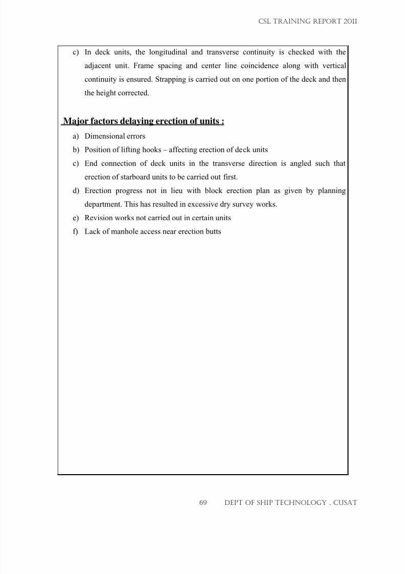
7/23/2019 CSL FINAL_3
http://slidepdf.com/reader/full/csl-final3 69/132
c) In deck units, the longitudinal and transverse continuity is checked with the
adjacent unit. Frame spacing and center line coincidence along with vertical
continuity is ensured. Strapping is carried out on one portion of the deck and then
the height corrected.
Major factors delaying erection of units :
a) Dimensional errors
b) Position of lifting hooks – affecting erection of deck units
c) End connection of deck units in the transverse direction is angled such that
erection of starboard units to be carried out first.
d) Erection progress not in lieu with block erection plan as given by planning
department. This has resulted in excessive dry survey works.
e) Revision works not carried out in certain units
f) Lack of manhole access near erection butts
CSL TRAINING REPORT 2011
69 DEPT OF SHIP TECHNOLOGY , CUSAT
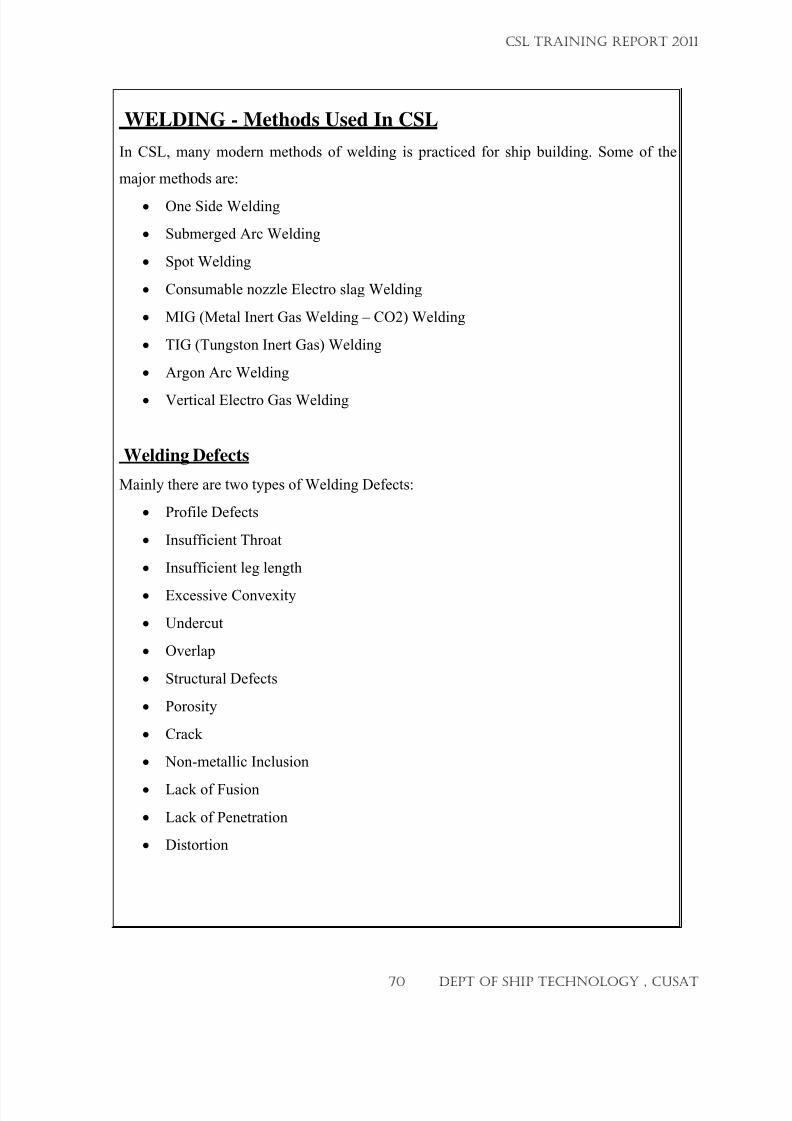
7/23/2019 CSL FINAL_3
http://slidepdf.com/reader/full/csl-final3 70/132
WELDING - Methods Used In CSL
In CSL, many modern methods of welding is practiced for ship building. Some of the
major methods are:
•
One Side Welding
• Submerged Arc Welding
• Spot Welding
• Consumable nozzle Electro slag Welding
• MIG (Metal Inert Gas Welding – CO2) Welding
• TIG (Tungston Inert Gas) Welding
• Argon Arc Welding
•
Vertical Electro Gas Welding
Welding Defects
Mainly there are two types of Welding Defects:
• Profile Defects
• Insufficient Throat
• Insufficient leg length
•
Excessive Convexity
• Undercut
• Overlap
• Structural Defects
• Porosity
• Crack
• Non-metallic Inclusion
•
Lack of Fusion
• Lack of Penetration
• Distortion
CSL TRAINING REPORT 2011
70 DEPT OF SHIP TECHNOLOGY , CUSAT
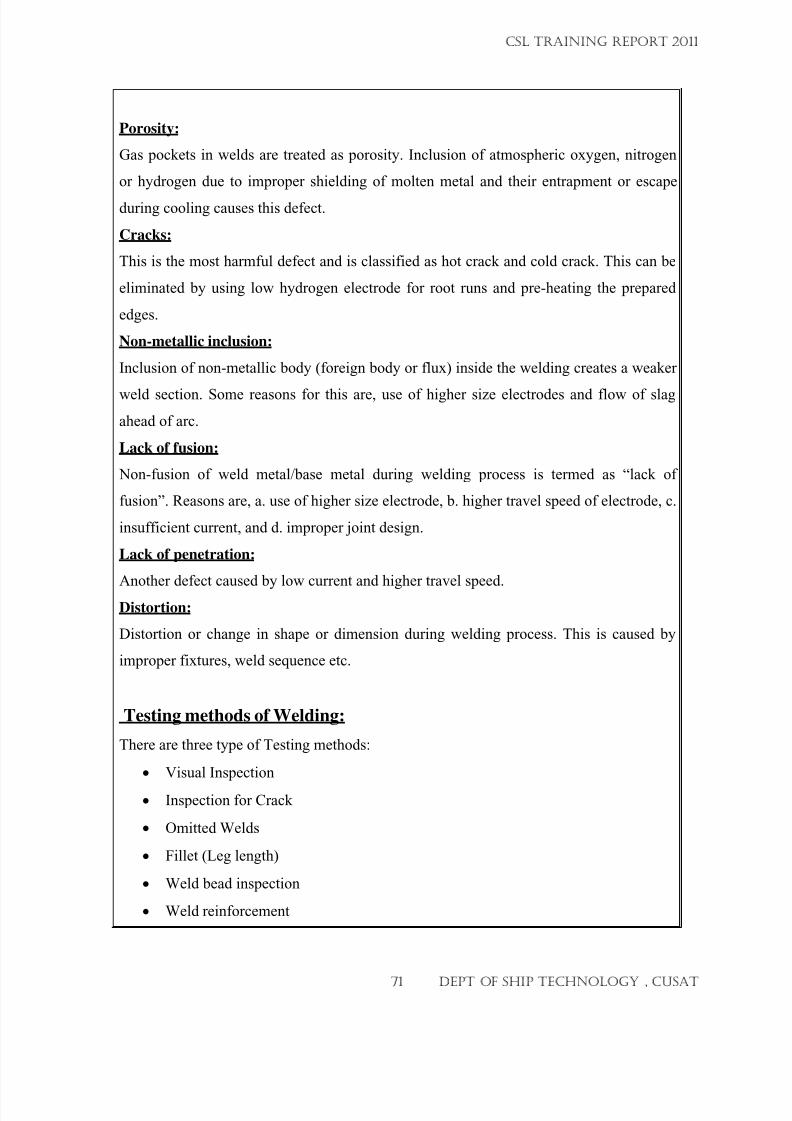
7/23/2019 CSL FINAL_3
http://slidepdf.com/reader/full/csl-final3 71/132
Porosity:
Gas pockets in welds are treated as porosity. Inclusion of atmospheric oxygen, nitrogen
or hydrogen due to improper shielding of molten metal and their entrapment or escape
during cooling causes this defect.
Cracks:
This is the most harmful defect and is classified as hot crack and cold crack. This can be
eliminated by using low hydrogen electrode for root runs and pre-heating the prepared
edges.
Non-metallic inclusion:
Inclusion of non-metallic body (foreign body or flux) inside the welding creates a weaker
weld section. Some reasons for this are, use of higher size electrodes and flow of slag
ahead of arc.
Lack of fusion:
Non-fusion of weld metal/base metal during welding process is termed as “lack of
fusion”. Reasons are, a. use of higher size electrode, b. higher travel speed of electrode, c.
insufficient current, and d. improper joint design.
Lack of penetration:
Another defect caused by low current and higher travel speed.
Distortion:
Distortion or change in shape or dimension during welding process. This is caused by
improper fixtures, weld sequence etc.
Testing methods of Welding:
There are three type of Testing methods:
• Visual Inspection
• Inspection for Crack
• Omitted Welds
• Fillet (Leg length)
• Weld bead inspection
• Weld reinforcement
CSL TRAINING REPORT 2011
71 DEPT OF SHIP TECHNOLOGY , CUSAT
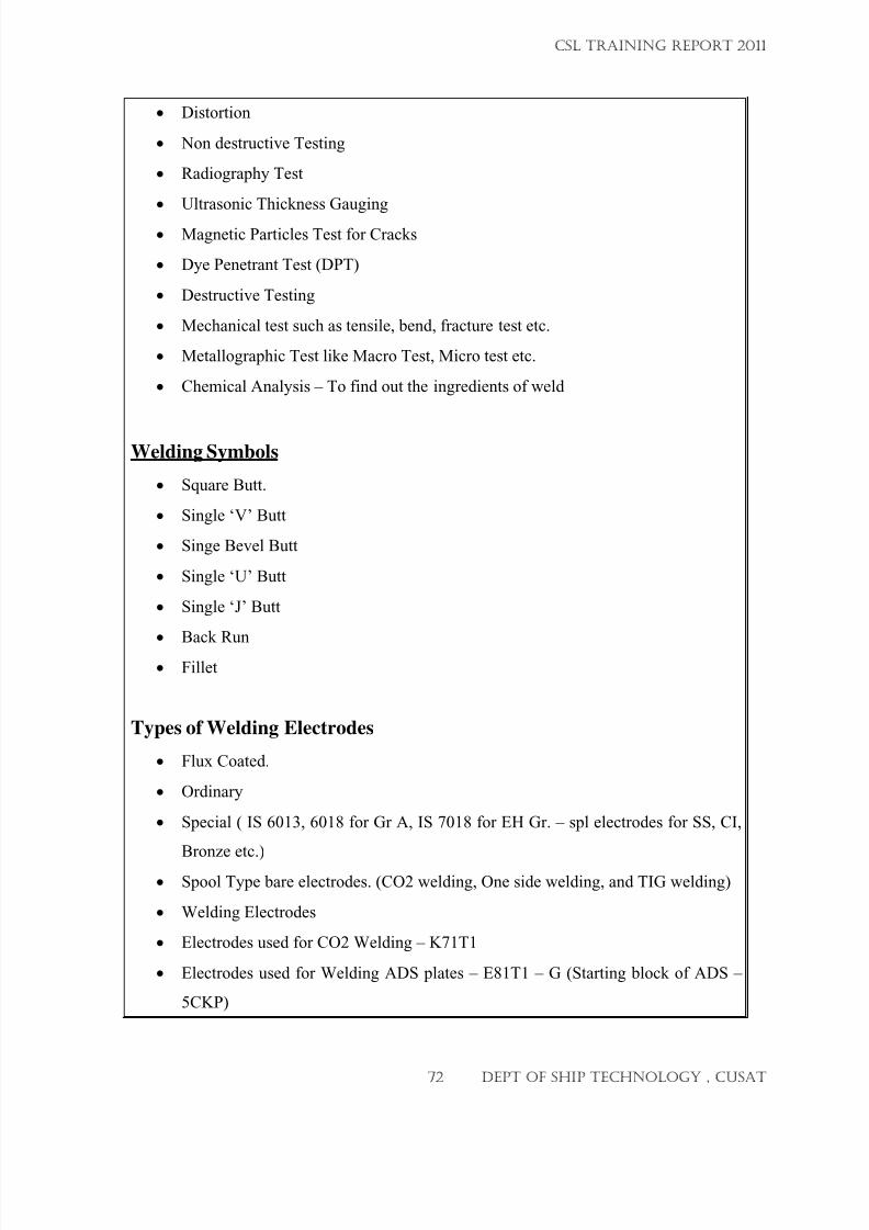
7/23/2019 CSL FINAL_3
http://slidepdf.com/reader/full/csl-final3 72/132
• Distortion
• Non destructive Testing
• Radiography Test
• Ultrasonic Thickness Gauging
• Magnetic Particles Test for Cracks
• Dye Penetrant Test (DPT)
• Destructive Testing
• Mechanical test such as tensile, bend, fracture test etc.
• Metallographic Test like Macro Test, Micro test etc.
• Chemical Analysis – To find out the ingredients of weld
Welding Symbols
• Square Butt.
• Single ‘V’ Butt
• Singe Bevel Butt
• Single ‘U’ Butt
• Single ‘J’ Butt
• Back Run
• Fillet
Types of Welding Electrodes
• Flux Coated.
• Ordinary
• Special ( IS 6013, 6018 for Gr A, IS 7018 for EH Gr. – spl electrodes for SS, CI,
Bronze etc.)
• Spool Type bare electrodes. (CO2 welding, One side welding, and TIG welding)
• Welding Electrodes
• Electrodes used for CO2 Welding – K71T1
• Electrodes used for Welding ADS plates – E81T1 – G (Starting block of ADS –
5CKP)
CSL TRAINING REPORT 2011
72 DEPT OF SHIP TECHNOLOGY , CUSAT
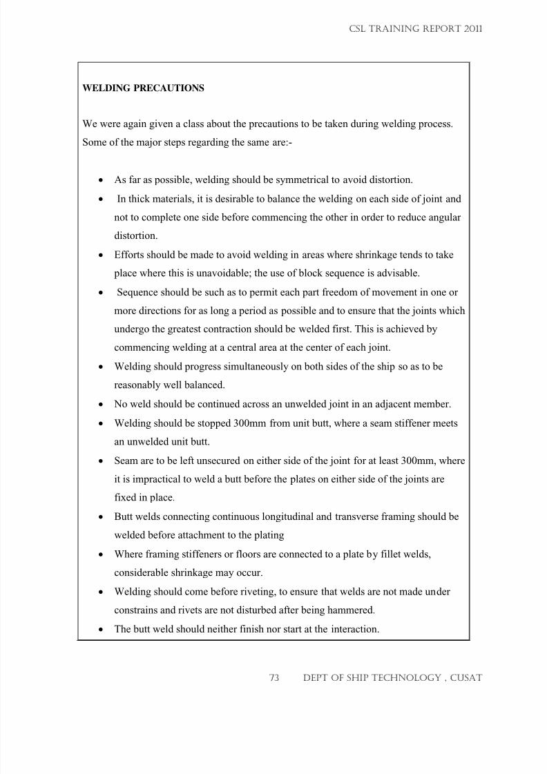
7/23/2019 CSL FINAL_3
http://slidepdf.com/reader/full/csl-final3 73/132
WELDING PRECAUTIONS
We were again given a class about the precautions to be taken during welding process.
Some of the major steps regarding the same are:-
• As far as possible, welding should be symmetrical to avoid distortion.
• In thick materials, it is desirable to balance the welding on each side of joint and
not to complete one side before commencing the other in order to reduce angular
distortion.
• Efforts should be made to avoid welding in areas where shrinkage tends to take
place where this is unavoidable; the use of block sequence is advisable.
• Sequence should be such as to permit each part freedom of movement in one or
more directions for as long a period as possible and to ensure that the joints which
undergo the greatest contraction should be welded first. This is achieved by
commencing welding at a central area at the center of each joint.
• Welding should progress simultaneously on both sides of the ship so as to be
reasonably well balanced.
•
No weld should be continued across an unwelded joint in an adjacent member.• Welding should be stopped 300mm from unit butt, where a seam stiffener meets
an unwelded unit butt.
• Seam are to be left unsecured on either side of the joint for at least 300mm, where
it is impractical to weld a butt before the plates on either side of the joints are
fixed in place.
• Butt welds connecting continuous longitudinal and transverse framing should be
welded before attachment to the plating
• Where framing stiffeners or floors are connected to a plate by fillet welds,
considerable shrinkage may occur.
• Welding should come before riveting, to ensure that welds are not made under
constrains and rivets are not disturbed after being hammered.
• The butt weld should neither finish nor start at the interaction.
CSL TRAINING REPORT 2011
73 DEPT OF SHIP TECHNOLOGY , CUSAT
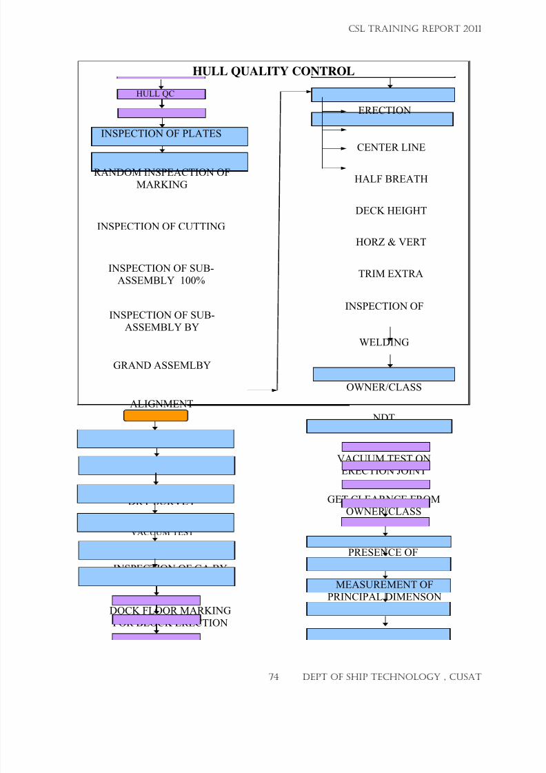
7/23/2019 CSL FINAL_3
http://slidepdf.com/reader/full/csl-final3 74/132
HULL QUALITY CONTROL
HULL QC
INSPECTION OF PLATES
RANDOM INSPEACTION OF
MARKING
INSPECTION OF CUTTING
INSPECTION OF SUB-ASSEMBLY 100%
INSPECTION OF SUB-ASSEMBLY BY
GRAND ASSEMLBY
FIT UP
VACUUM TEST
DRY SURVEY
WELDING
ALIGNMENT
INSPECTION OF GA BY
OWNER/CLASS
HORZ & VERT
CENTER LINE
HALF BREATH
DECK HEIGHT
TRIM EXTRA
DOCK FLOOR MARKING
FOR BLOCK ERECTION
INSPECTION OF
WELDING
DRY SURVEY BYOWNER/CLASS
NDT
VACUUM TEST ONERECTION JOINT
GET CLEARNCE FROMOWNER/CLASS
ERECTION
KEEL SIGHTING IN THEPRESENCE OF
MEASUREMENT OFPRINCIPAL DIMENSON
CSL TRAINING REPORT 2011
74 DEPT OF SHIP TECHNOLOGY , CUSAT
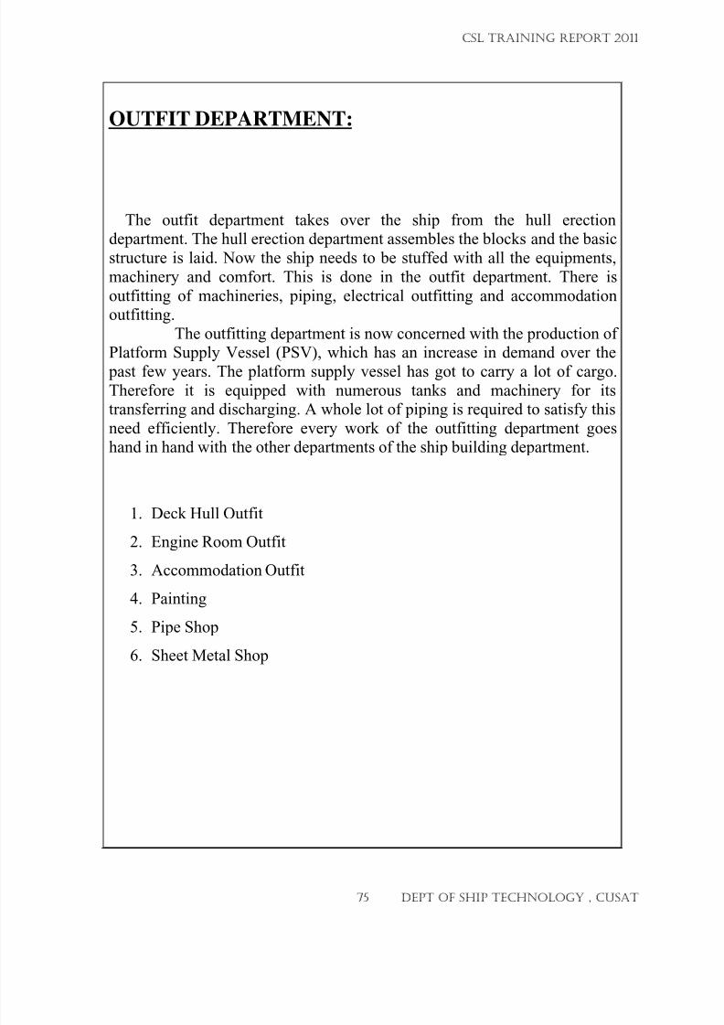
7/23/2019 CSL FINAL_3
http://slidepdf.com/reader/full/csl-final3 75/132
OUTFIT DEPARTMENT:
The outfit department takes over the ship from the hull erectiondepartment. The hull erection department assembles the blocks and the basic
structure is laid. Now the ship needs to be stuffed with all the equipments,
machinery and comfort. This is done in the outfit department. There is
outfitting of machineries, piping, electrical outfitting and accommodationoutfitting.
The outfitting department is now concerned with the production of
Platform Supply Vessel (PSV), which has an increase in demand over the past few years. The platform supply vessel has got to carry a lot of cargo.
Therefore it is equipped with numerous tanks and machinery for itstransferring and discharging. A whole lot of piping is required to satisfy this
need efficiently. Therefore every work of the outfitting department goeshand in hand with the other departments of the ship building department.
1.
Deck Hull Outfit
2.
Engine Room Outfit
3. Accommodation Outfit
4. Painting
5. Pipe Shop
6. Sheet Metal Shop
CSL TRAINING REPORT 2011
75 DEPT OF SHIP TECHNOLOGY , CUSAT
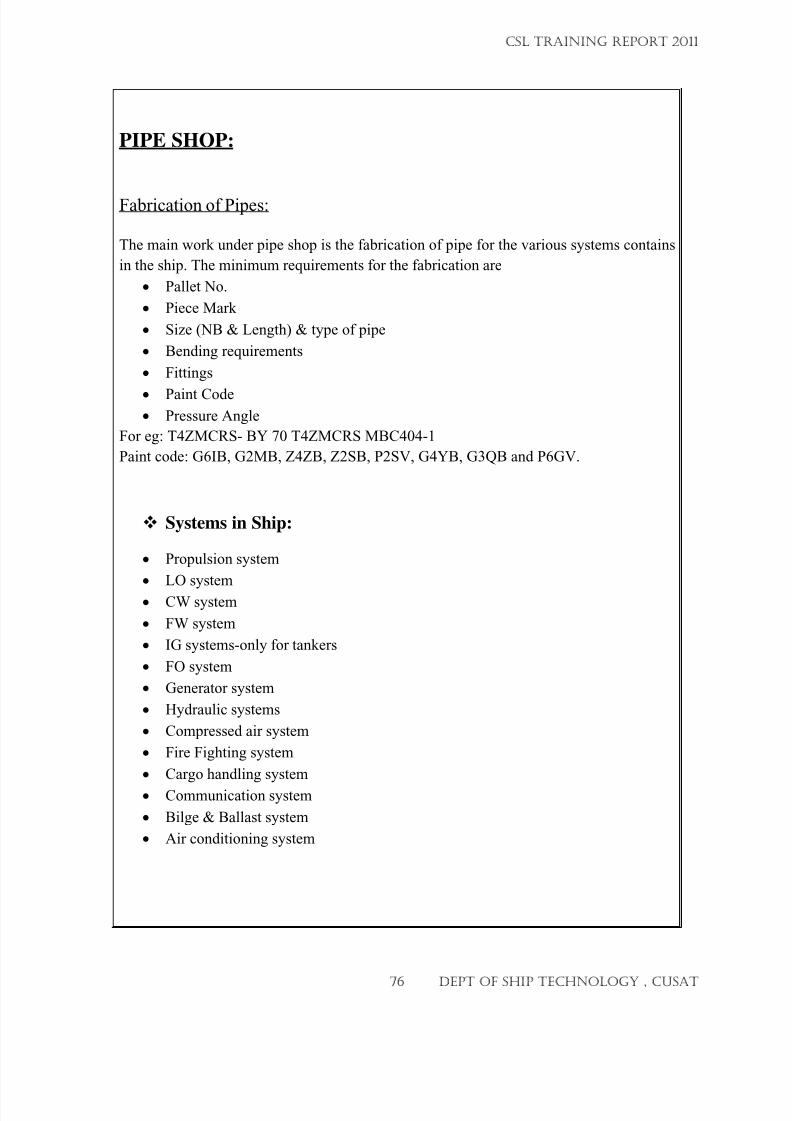
7/23/2019 CSL FINAL_3
http://slidepdf.com/reader/full/csl-final3 76/132
PIPE SHOP:
Fabrication of Pipes:
The main work under pipe shop is the fabrication of pipe for the various systems contains
in the ship. The minimum requirements for the fabrication are
• Pallet No.
• Piece Mark
• Size (NB & Length) & type of pipe
• Bending requirements
• Fittings
•
Paint Code• Pressure Angle
For eg: T4ZMCRS- BY 70 T4ZMCRS MBC404-1
Paint code: G6IB, G2MB, Z4ZB, Z2SB, P2SV, G4YB, G3QB and P6GV.
Systems in Ship:
• Propulsion system
• LO system
• CW system
• FW system
• IG systems-only for tankers
• FO system
• Generator system
• Hydraulic systems
• Compressed air system
• Fire Fighting system
• Cargo handling system
•
Communication system
• Bilge & Ballast system
• Air conditioning system
CSL TRAINING REPORT 2011
76 DEPT OF SHIP TECHNOLOGY , CUSAT
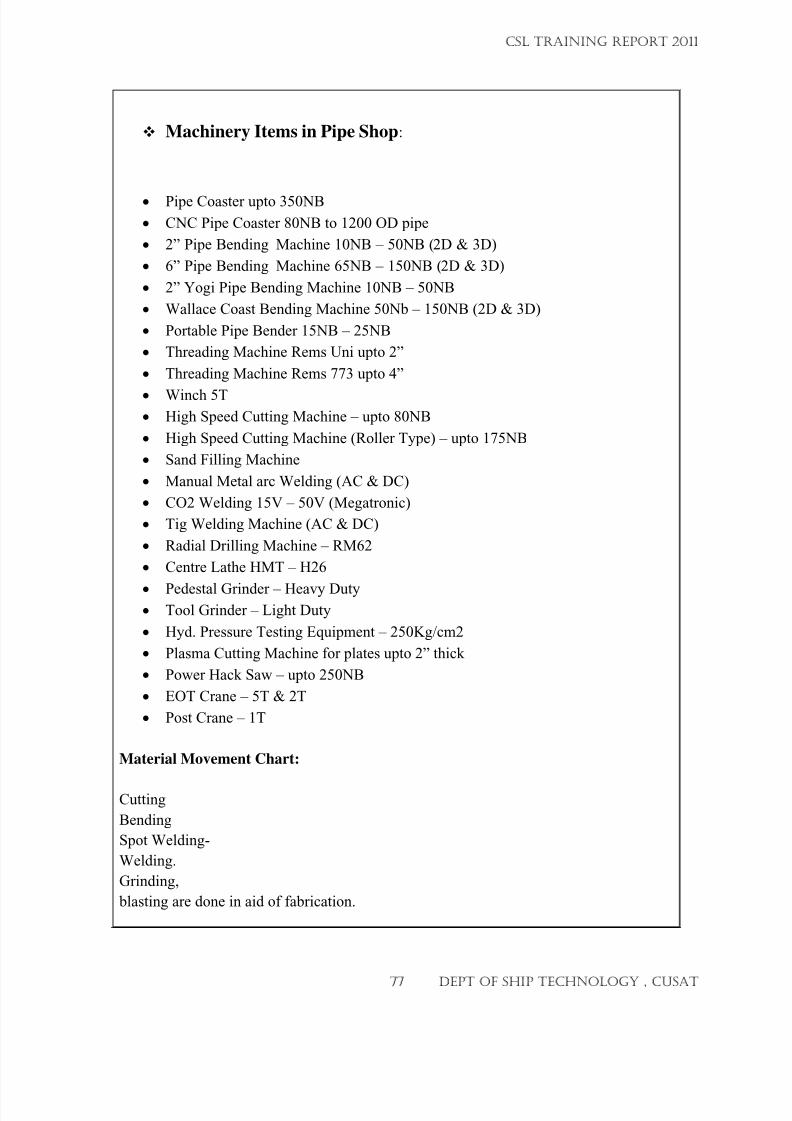
7/23/2019 CSL FINAL_3
http://slidepdf.com/reader/full/csl-final3 77/132
Machinery Items in Pipe Shop:
•
Pipe Coaster upto 350NB
• CNC Pipe Coaster 80NB to 1200 OD pipe
• 2” Pipe Bending Machine 10NB – 50NB (2D & 3D)
• 6” Pipe Bending Machine 65NB – 150NB (2D & 3D)
• 2” Yogi Pipe Bending Machine 10NB – 50NB
• Wallace Coast Bending Machine 50Nb – 150NB (2D & 3D)
• Portable Pipe Bender 15NB – 25NB
• Threading Machine Rems Uni upto 2”
• Threading Machine Rems 773 upto 4”
•
Winch 5T
• High Speed Cutting Machine – upto 80NB
• High Speed Cutting Machine (Roller Type) – upto 175NB
• Sand Filling Machine
• Manual Metal arc Welding (AC & DC)
• CO2 Welding 15V – 50V (Megatronic)
• Tig Welding Machine (AC & DC)
• Radial Drilling Machine – RM62
• Centre Lathe HMT – H26
•
Pedestal Grinder – Heavy Duty• Tool Grinder – Light Duty
• Hyd. Pressure Testing Equipment – 250Kg/cm2
• Plasma Cutting Machine for plates upto 2” thick
• Power Hack Saw – upto 250NB
• EOT Crane – 5T & 2T
• Post Crane – 1T
Material Movement Chart:
Cutting
Bending
Spot Welding-
Welding.
Grinding,
blasting are done in aid of fabrication.
CSL TRAINING REPORT 2011
77 DEPT OF SHIP TECHNOLOGY , CUSAT
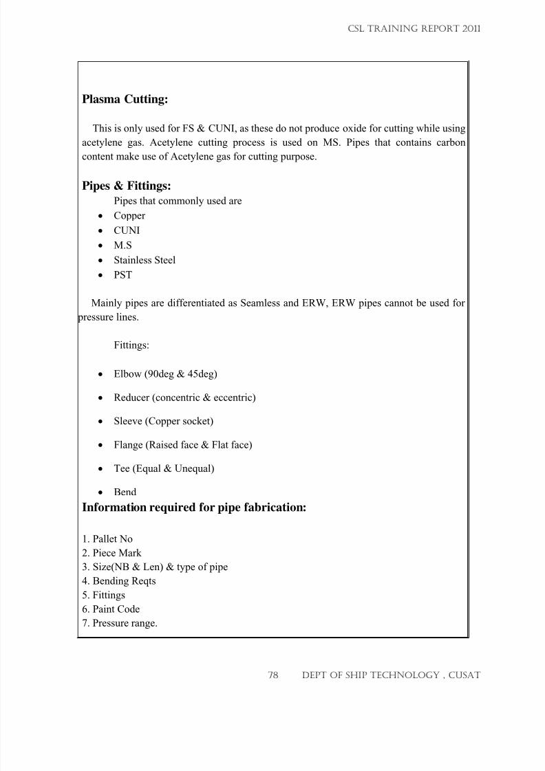
7/23/2019 CSL FINAL_3
http://slidepdf.com/reader/full/csl-final3 78/132
Plasma Cutting:
This is only used for FS & CUNI, as these do not produce oxide for cutting while using
acetylene gas. Acetylene cutting process is used on MS. Pipes that contains carbon
content make use of Acetylene gas for cutting purpose.
Pipes & Fittings:
Pipes that commonly used are
• Copper
• CUNI
• M.S
• Stainless Steel
•
PST
Mainly pipes are differentiated as Seamless and ERW, ERW pipes cannot be used for
pressure lines.
Fittings:
• Elbow (90deg & 45deg)
• Reducer (concentric & eccentric)
• Sleeve (Copper socket)
• Flange (Raised face & Flat face)
• Tee (Equal & Unequal)
• Bend
Information required for pipe fabrication:
1. Pallet No2. Piece Mark
3. Size(NB & Len) & type of pipe
4. Bending Reqts
5. Fittings
6. Paint Code
7. Pressure range.
CSL TRAINING REPORT 2011
78 DEPT OF SHIP TECHNOLOGY , CUSAT
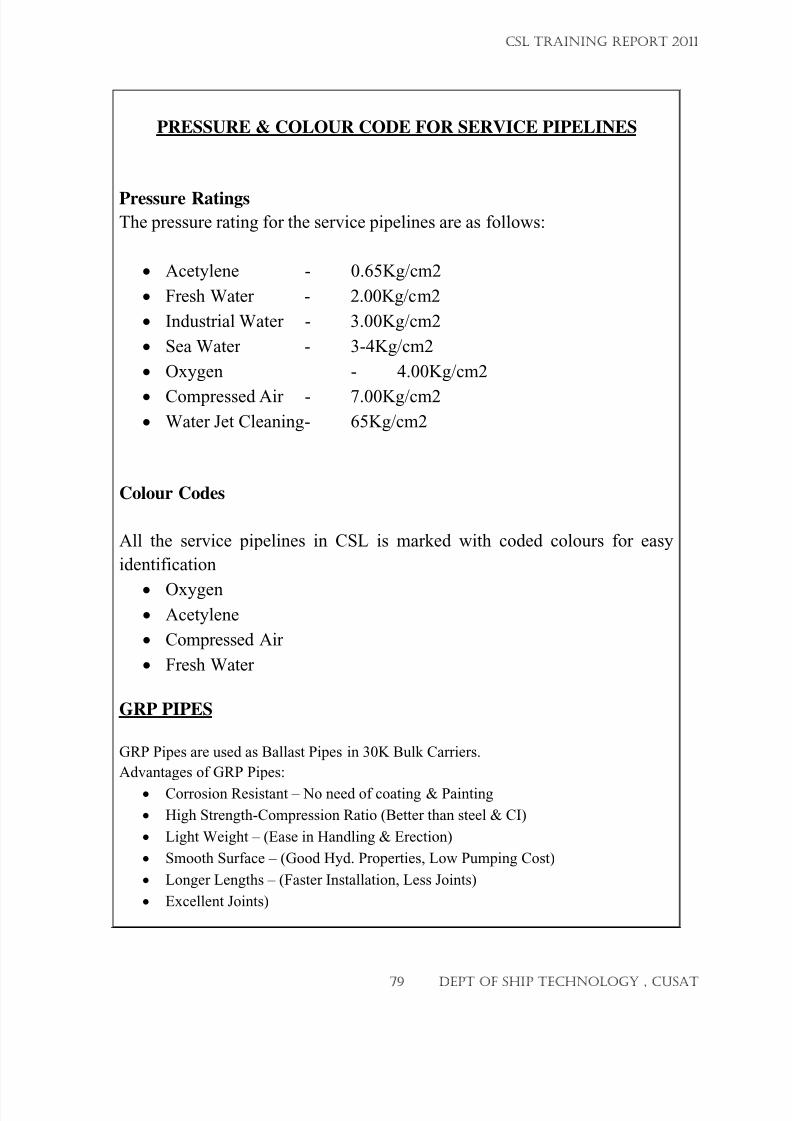
7/23/2019 CSL FINAL_3
http://slidepdf.com/reader/full/csl-final3 79/132
PRESSURE & COLOUR CODE FOR SERVICE PIPELINES
Pressure RatingsThe pressure rating for the service pipelines are as follows:
• Acetylene - 0.65Kg/cm2
• Fresh Water - 2.00Kg/cm2
• Industrial Water - 3.00Kg/cm2
• Sea Water - 3-4Kg/cm2
• Oxygen - 4.00Kg/cm2
•
Compressed Air - 7.00Kg/cm2
• Water Jet Cleaning - 65Kg/cm2
Colour Codes
All the service pipelines in CSL is marked with coded colours for easy
identification
•
Oxygen• Acetylene
• Compressed Air
• Fresh Water
GRP PIPES
GRP Pipes are used as Ballast Pipes in 30K Bulk Carriers.
Advantages of GRP Pipes:
•
Corrosion Resistant – No need of coating & Painting
• High Strength-Compression Ratio (Better than steel & CI)
• Light Weight – (Ease in Handling & Erection)
• Smooth Surface – (Good Hyd. Properties, Low Pumping Cost)
• Longer Lengths – (Faster Installation, Less Joints)
• Excellent Joints)
CSL TRAINING REPORT 2011
79 DEPT OF SHIP TECHNOLOGY , CUSAT
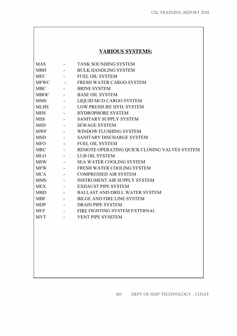
7/23/2019 CSL FINAL_3
http://slidepdf.com/reader/full/csl-final3 80/132
VARIOUS SYSTEMS:
MAS - TANK SOUNDING SYSTEM
MBH - BULK HANDLING SYSTEM
MFC - FUEL OIL SYSTEM
MFWC - FRESH WATER CARGO SYSTEM
MBC - BRINE SYSTEM
MBOC - BASE OIL SYSTEM
MMS - LIQUID MUD CARGO SYSTEM
MLHS - LOW PRESSURE HYD. SYSTEM
MHS - HYDROPHORE SYSTEM
MSS - SANITARY SUPPLY SYSTEM
MSD - SEWAGE SYSTEM
MWF - WINDOW FLUSHING SYSTEM
MSD - SANITARY DISCHARGE SYSTEM
MFO - FUEL OIL SYSTEM
MRC - REMOTE OPERATING QUICK CLOSING VALVES SYSTEM
MLO - LUB OIL SYSTEM
MSW - SEA WATER COOLING SYSTEM
MFW - FRESH WATER COOLING SYSTEM
MCA - COMPRESSED AIR SYSTEMMMS - INSTRUMENT AIR SUPPLY SYSTEM
MEX - EXHAUST PIPE SYSTEM
MBD - BALLAST AND DRILL WATER SYSTEM
MBF - BILGE AND FIRE LINE SYSTEM
MDP - DRAIN PIPE SYSTEM
MEF - FIRE FIGHTING SYSTEM EXTERNAL
MVT - VENT PIPE SYSSTEM
CSL TRAINING REPORT 2011
80 DEPT OF SHIP TECHNOLOGY , CUSAT
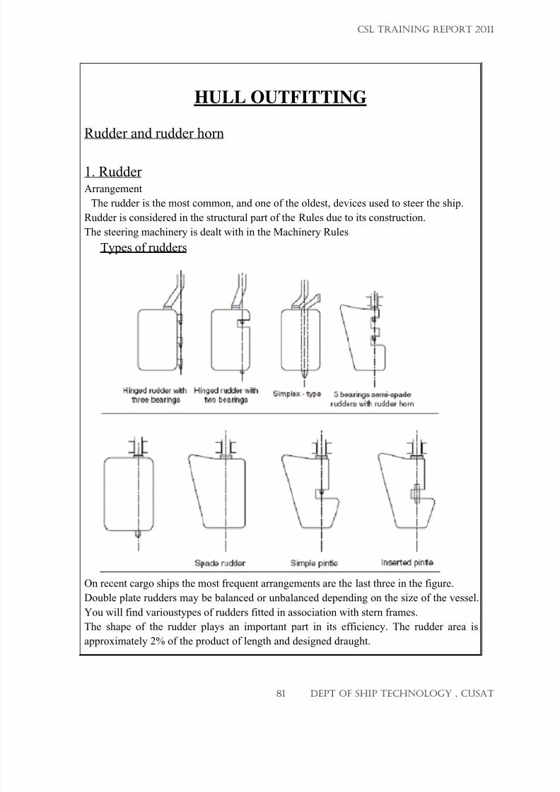
7/23/2019 CSL FINAL_3
http://slidepdf.com/reader/full/csl-final3 81/132
InSQ rt ;d pln Q
imp lQ p in t lQpada ru d der
Hingedruddirrvmh Hingedru:l:l~r
w ilh
S imp lex type DMringasemi apade
1hreebearinQ3 tIIll bearing rudderg J ilh udde bern
HULL OUTFITTING
Rudder and rudder horn
1. RudderArrangement
The rudder is the most common, and one of the oldest, devices used to steer the ship.
Rudder is considered in the structural part of the Rules due to its construction.
The steering machinery is dealt with in the Machinery Rules
Types of rudders
On recent cargo ships the most frequent arrangements are the last three in the figure.
Double plate rudders may be balanced or unbalanced depending on the size of the vessel.
You will find varioustypes of rudders fitted in association with stern frames.
The shape of the rudder plays an important part in its efficiency. The rudder area is
approximately 2% of the product of length and designed draught.
CSL TRAINING REPORT 2011
81 DEPT OF SHIP TECHNOLOGY , CUSAT
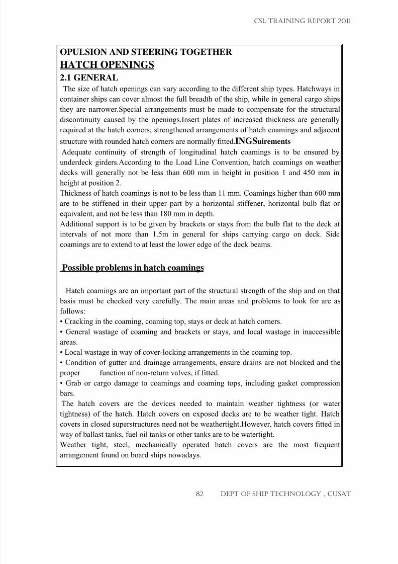
7/23/2019 CSL FINAL_3
http://slidepdf.com/reader/full/csl-final3 82/132
OPULSION AND STEERING TOGETHER
HATCH OPENINGS
2.1 GENERAL
The size of hatch openings can vary according to the different ship types. Hatchways in
container ships can cover almost the full breadth of the ship, while in general cargo shipsthey are narrower.Special arrangements must be made to compensate for the structural
discontinuity caused by the openings.Insert plates of increased thickness are generally
required at the hatch corners; strengthened arrangements of hatch coamings and adjacent
structure with rounded hatch corners are normally fitted.INGSuirements
Adequate continuity of strength of longitudinal hatch coamings is to be ensured by
underdeck girders.According to the Load Line Convention, hatch coamings on weather
decks will generally not be less than 600 mm in height in position 1 and 450 mm in
height at position 2.
Thickness of hatch coamings is not to be less than 11 mm. Coamings higher than 600 mm
are to be stiffened in their upper part by a horizontal stiffener, horizontal bulb flat or
equivalent, and not be less than 180 mm in depth.
Additional support is to be given by brackets or stays from the bulb flat to the deck at
intervals of not more than 1.5m in general for ships carrying cargo on deck. Side
coamings are to extend to at least the lower edge of the deck beams.
Possible problems in hatch coamings
Hatch coamings are an important part of the structural strength of the ship and on that
basis must be checked very carefully. The main areas and problems to look for are as
follows:
• Cracking in the coaming, coaming top, stays or deck at hatch corners.
• General wastage of coaming and brackets or stays, and local wastage in inaccessible
areas.
• Local wastage in way of cover-locking arrangements in the coaming top.
• Condition of gutter and drainage arrangements, ensure drains are not blocked and the
proper function of non-return valves, if fitted.
• Grab or cargo damage to coamings and coaming tops, including gasket compression
bars.The hatch covers are the devices needed to maintain weather tightness (or water
tightness) of the hatch. Hatch covers on exposed decks are to be weather tight. Hatch
covers in closed superstructures need not be weathertight.However, hatch covers fitted in
way of ballast tanks, fuel oil tanks or other tanks are to be watertight.
Weather tight, steel, mechanically operated hatch covers are the most frequent
arrangement found on board ships nowadays.
CSL TRAINING REPORT 2011
82 DEPT OF SHIP TECHNOLOGY , CUSAT
7/23/2019 CSL FINAL_3
http://slidepdf.com/reader/full/csl-final3 83/132
DOORS
OPENINGS IN WATERTIGHT BULKHEADS
Openings can be arranged in watertight bulkheads under certain conditions and
requirements.
Different requirements are provided for different types of openings, and taking into
account the
operational mode of the opening, in particular:
• Opening used while at sea
• Opening normally closed at sea
• Opening permanently kept closed at sea
TYPES OF CARGO DOORS
Cargo doors are fitted in certain trades to provide access to between deck spaces, lift
trucks from the quay into the tween deck. Openings are cut into the shell plating and
arrangements must be made to maintain the strength, particularly in a longitudinal
dimension. The corners of all openings should be well rounded to avoid stress
concentration.
Typical are:
•
cargo ports - to facilitate the loading of stores, etc. - manually or hydraulically
operated, secured by closely
• spaced dogs or bolts
• slide doors, simple and fast to operate, hydraulically self closing, since the door is
forced against the perimeter of the opening due to the eccentric path of its guide
rollers
CSL TRAINING REPORT 2011
83 DEPT OF SHIP TECHNOLOGY , CUSAT
7/23/2019 CSL FINAL_3
http://slidepdf.com/reader/full/csl-final3 84/132
BULWARKS, GUARD RAILS
Bulkwarks and guard rails are fitted for the safety of the passengers and crew, and playno part in the structural strength of the vessel. They are usually 1 metre in height. Plated
bulwarks must be stiffened by a strong rail section and supported by stays from the
deck.Fitting of stays should be at every alternate frame. The stays should be fitted above
deck beams, beam knees or carlings. Flat bars will mostly be provided at the lower part
which will be effectively connected to the deck plating by welding. The thickness of the
bulwark plating forward, particularly where exposed to the wash of the sea, should be
increased and be equal to the thickness of the forecastle side plating. Where bulkwarks
form wells, ample provision should be made for freeing the decks of water as rapidly as
possible,so freeing ports must be provided. The area for freeing the decks on each side of
the vessel depends on the length of the well and should be properly calculated.
The lower port of the freeing point will be as near as possible to the deck and the
openings should be protected by rails spaced no more than 230 mm apart. If hinged doors
or shutters are fitted to freeing ports, they must have ample clearance to prevent jamming
and the pins or bearings must be made of corrosion resistant material.
If the construction of bulwarks were made integral with the sheerstrake, then the light
plating of the bulkwarks would be subjected to considerable stress with the possibility of
subsequent fracture.That would create a notch at the sheerstrake and might give rise to aserious structural fracture.Particularly for ships where the strength deck is made of higher
tensile steel, smooth transitions should be provided at the end connection of the flat bar
faces to deck. An adequate number of expansion joints is to be provided in the bulkwark.
Sufficient flexibility of the stays adjacent to the expansion joints should also be provided.
The design of bulkwarks’ connection to deckhouse supports should be such as to avoid
cracks. Openings in the bulwarks must be sufficiently distant from the end bulkheads of
superstructures.Openings in bulwarks are to be arranged so that the protection of the crew
is to be at least equivalent to that provided by the horizontal courses.
For this purpose, vertical rails or bars spaced approximately 230 mm apart may be
accepted in lieu of rails or bars arranged horizontally.Where guard rails are fitted, they will consist of courses of rails supported by stanchions
efficiently connected to the deck. The opening between the lowest course of rails and the
deck should not exceed 230 mm in height. Above that, course openings should not
exceed 380 mm in height. Where the vessel has a rounded gunwale, the stanchions must
be secured at the perimeter of the flat of the deck.
CSL TRAINING REPORT 2011
84 DEPT OF SHIP TECHNOLOGY , CUSAT
7/23/2019 CSL FINAL_3
http://slidepdf.com/reader/full/csl-final3 85/132
VENTILATORS
5.1 PURPOSE
Ventilators are necessary to give adequate air circulation to under deck spaces,
accommodation and tanks.
REQUIREMENTS
The coamings must have a minimum height above the surface of weather decks of 900
mm in position 1 and 760mm in position 2, see the Load Line Convention for details.
Where coamings exceed 900 mm in height they must be specially stayed.
All ventilator coamings are to be supplied with strong covers unless the height of the
coaming exceeds 4.5
Special care has to be taken with the design and positioning of ventilator openings and
coamings, particularly in regions of high stress concentration. Mushroom, gooseneck and
other similar minor ventilators will be strongly constructed and efficiently secured to the
deck.
Goose or swan neck type ventilators are mainly used for the air pipes to tanks. The
height of the opening must be not less than 760 mm on the freeboard deck and 450 mm
on the superstructure deck. Air pipes must be fitted at the opposite end of the tank to that
at which the filling pipe is placed and/or at the highest point of the tank.Sounding pipes
should be as straight as possible and should have a bore of not less than 32mm. Striking
plates of adequate thickness and size must be fitted under open- ended sounding pipes.
Air pipes, ventilators and their closing devices in the fore part of the ship (exposed decks
forward are to be designed considering the forces due to water on deck (green sea forces).
According to these forces the welding or flange connections, the toes of supporting
brackets and the penetration pieces are to be checked for stresses.
.
TO BE CHECKED
For ventilators on the main deck and accommodation, which require weathertight
closures, including wall ventilators in accommodation, the conditions of the following
items are checked during surveys:
• coamings (for possible damage or wastage, especially in areas of difficult access,
particularly the areas
• close to bulwarks)
• lid, sealing gasket and retaining channel
• hinges and dogs or clips
CSL TRAINING REPORT 2011
85 DEPT OF SHIP TECHNOLOGY , CUSAT
7/23/2019 CSL FINAL_3
http://slidepdf.com/reader/full/csl-final3 86/132
MOORING AND TOWING EQUIPMENT
PARTS OF THE MOORING / TOWING EQUIPMENT
1. Anchor windlass
An anchor windlass is, generally located on the forecastle, designed to raise or lower an
anchor; it consists of a horizontal barrel that is fitted with gearlike projections that engage
the links of the anchor chain, and is turned by steam or electrical power. Also known as
windlass.
2. BollardA bollard is a post used for mooring the ship, around which rope lines are secured.
3.CHAFING GEAR
Covering (usually rope or canvas) of a line or spar to protect it from friction
4. Chain locker
A compartment for stowing an anchor chain.
5. Chain stopper
A short chain with a hook attached to a ship's forecastle, used to secure the anchor chain
when the anchor is raised or lowered, thus relieving the windlass from strain, or to
quickly release the anchor.
6. Chain stopper
A cleat is device attaching a rope. The traditional design is attached to a flat surface and
features two “horns” extending parallel to the deck.
7. Eyebolts
A bolt having a looped head designed to receive a hook or rope.
8. Fairlead
A pulley-block used to guide a rope forming part of a ship's rigging to avoid chafing
Fairlead
9. Hawse pipe
CSL TRAINING REPORT 2011
86 DEPT OF SHIP TECHNOLOGY , CUSAT
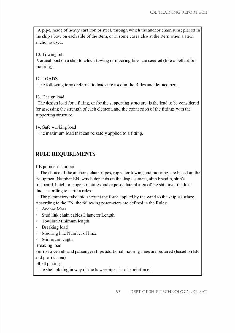
7/23/2019 CSL FINAL_3
http://slidepdf.com/reader/full/csl-final3 87/132
A pipe, made of heavy cast iron or steel, through which the anchor chain runs; placed in
the ship's bow on each side of the stem, or in some cases also at the stern when a stern
anchor is used.
10. Towing bitt
Vertical post on a ship to which towing or mooring lines are secured (like a bollard for
mooring).
12. LOADS
The following terms referred to loads are used in the Rules and defined here.
13. Design load
The design load for a fitting, or for the supporting structure, is the load to be considered
for assessing the strength of each element, and the connection of the fittings with the
supporting structure.
14. Safe working load
The maximum load that can be safely applied to a fitting.
RULE REQUIREMENTS
1 Equipment number
The choice of the anchors, chain ropes, ropes for towing and mooring, are based on theEquipment Number EN, which depends on the displacement, ship breadth, ship’s
freeboard, height of superstructures and exposed lateral area of the ship over the load
line, according to certain rules.
The parameters take into account the force applied by the wind to the ship’s surface.
According to the EN, the following parameters are defined in the Rules:
• Anchor Mass
• Stud link chain cables Diameter Length
• Towline Minimum length
• Breaking load
•
Mooring line Number of lines• Minimum length
Breaking load
For ro-ro vessels and passenger ships additional mooring lines are required (based on EN
and profile area).
Shell plating
The shell plating in way of the hawse pipes is to be reinforced.
CSL TRAINING REPORT 2011
87 DEPT OF SHIP TECHNOLOGY , CUSAT
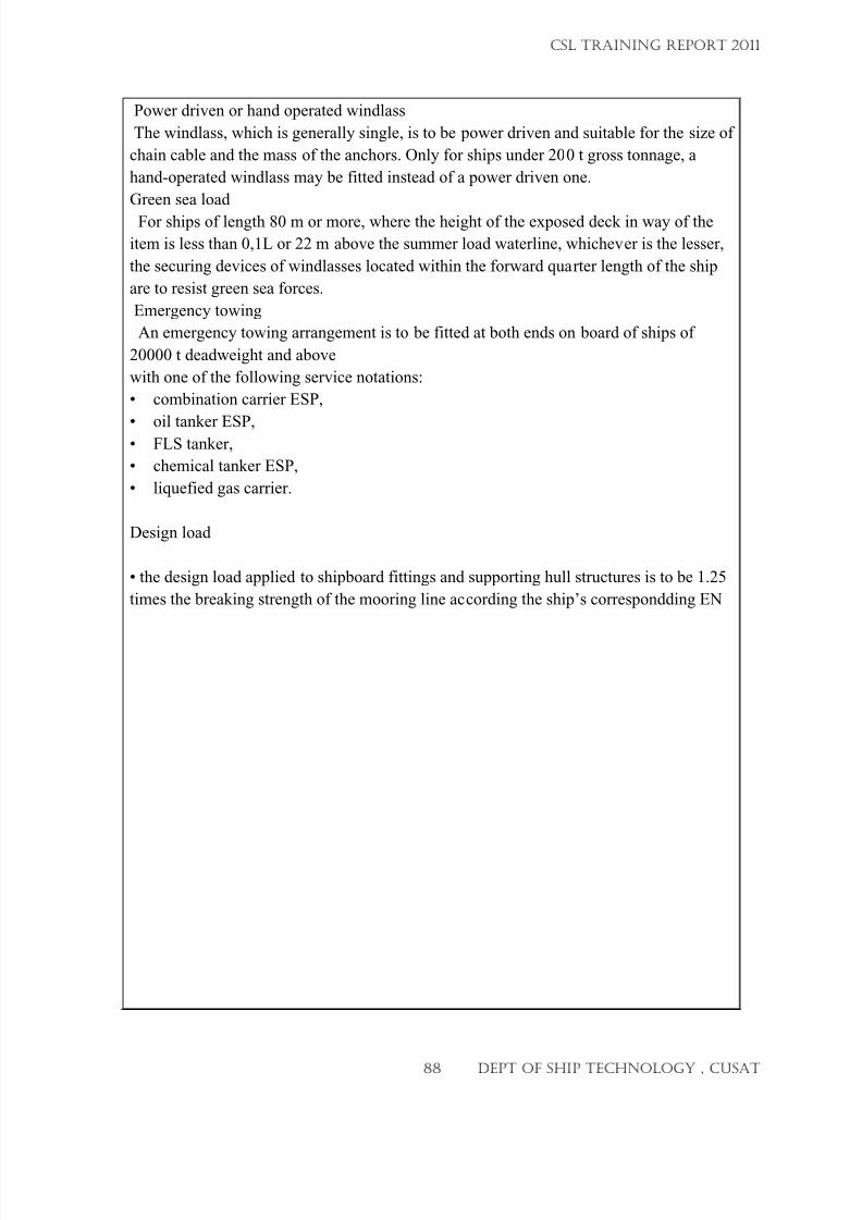
7/23/2019 CSL FINAL_3
http://slidepdf.com/reader/full/csl-final3 88/132
Power driven or hand operated windlass
The windlass, which is generally single, is to be power driven and suitable for the size of
chain cable and the mass of the anchors. Only for ships under 200 t gross tonnage, a
hand-operated windlass may be fitted instead of a power driven one.
Green sea load
For ships of length 80 m or more, where the height of the exposed deck in way of the
item is less than 0,1L or 22 m above the summer load waterline, whichever is the lesser,
the securing devices of windlasses located within the forward quarter length of the ship
are to resist green sea forces.
Emergency towing
An emergency towing arrangement is to be fitted at both ends on board of ships of
20000 t deadweight and above
with one of the following service notations:
• combination carrier ESP,
•
oil tanker ESP,• FLS tanker,
• chemical tanker ESP,
• liquefied gas carrier.
Design load
• the design load applied to shipboard fittings and supporting hull structures is to be 1.25
times the breaking strength of the mooring line according the ship’s correspondding EN
CSL TRAINING REPORT 2011
88 DEPT OF SHIP TECHNOLOGY , CUSAT
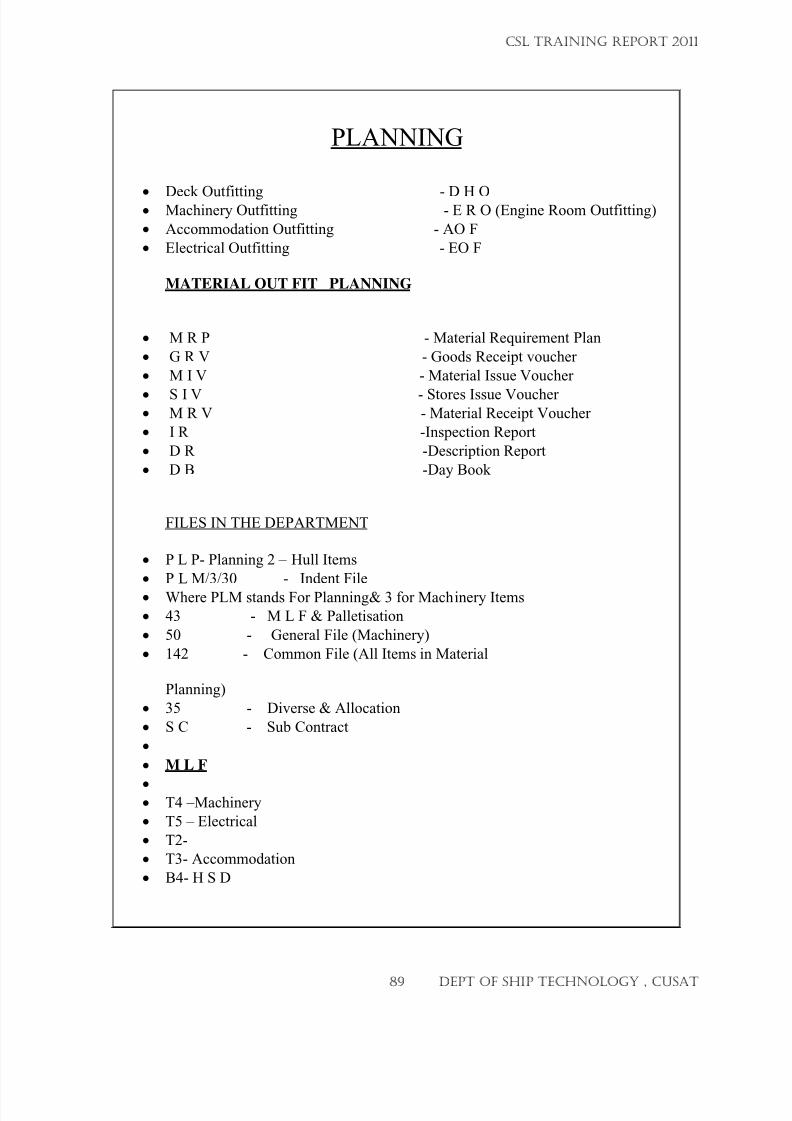
7/23/2019 CSL FINAL_3
http://slidepdf.com/reader/full/csl-final3 89/132
PLANNING
• Deck Outfitting - D H O
• Machinery Outfitting - E R O (Engine Room Outfitting)
• Accommodation Outfitting - AO F
• Electrical Outfitting - EO F
MATERIAL OUT FIT PLANNING
• M R P - Material Requirement Plan
• G R V - Goods Receipt voucher
• M I V - Material Issue Voucher
•
S I V - Stores Issue Voucher• M R V - Material Receipt Voucher
• I R -Inspection Report
• D R -Description Report
• D B -Day Book
FILES IN THE DEPARTMENT
• P L P- Planning 2 – Hull Items
• P L M/3/30 - Indent File
•
Where PLM stands For Planning& 3 for Machinery Items
• 43 - M L F & Palletisation
• 50 - General File (Machinery)
• 142 - Common File (All Items in Material
Planning)
• 35 - Diverse & Allocation
• S C - Sub Contract
•
• M L F
•
• T4 –Machinery
• T5 – Electrical
• T2-
• T3- Accommodation
• B4- H S D
CSL TRAINING REPORT 2011
89 DEPT OF SHIP TECHNOLOGY , CUSAT
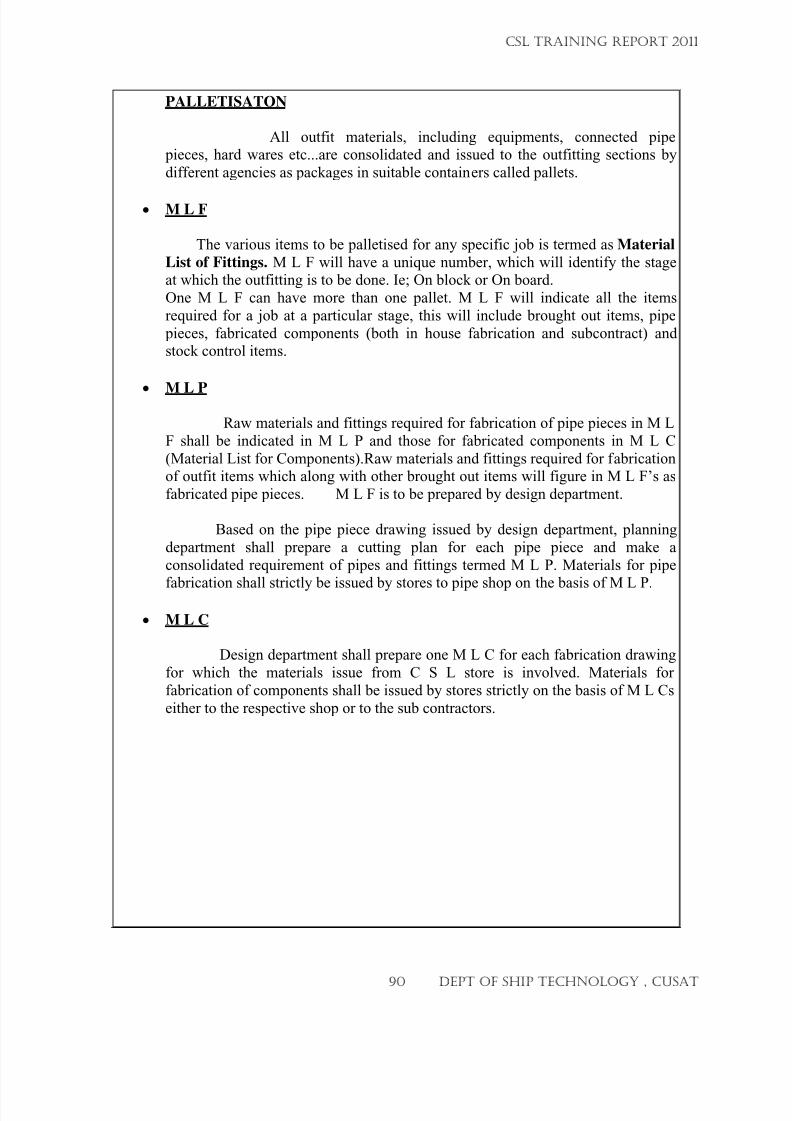
7/23/2019 CSL FINAL_3
http://slidepdf.com/reader/full/csl-final3 90/132
PALLETISATON
All outfit materials, including equipments, connected pipe pieces, hard wares etc...are consolidated and issued to the outfitting sections by
different agencies as packages in suitable containers called pallets.
• M L F
The various items to be palletised for any specific job is termed as Material
List of Fittings. M L F will have a unique number, which will identify the stageat which the outfitting is to be done. Ie; On block or On board.
One M L F can have more than one pallet. M L F will indicate all the items
required for a job at a particular stage, this will include brought out items, pipe
pieces, fabricated components (both in house fabrication and subcontract) andstock control items.
• M L P
Raw materials and fittings required for fabrication of pipe pieces in M L
F shall be indicated in M L P and those for fabricated components in M L C
(Material List for Components).Raw materials and fittings required for fabricationof outfit items which along with other brought out items will figure in M L F’s as
fabricated pipe pieces. M L F is to be prepared by design department.
Based on the pipe piece drawing issued by design department, planning
department shall prepare a cutting plan for each pipe piece and make a
consolidated requirement of pipes and fittings termed M L P. Materials for pipe
fabrication shall strictly be issued by stores to pipe shop on the basis of M L P.
• M L C
Design department shall prepare one M L C for each fabrication drawing
for which the materials issue from C S L store is involved. Materials for
fabrication of components shall be issued by stores strictly on the basis of M L Cs
either to the respective shop or to the sub contractors.
CSL TRAINING REPORT 2011
90 DEPT OF SHIP TECHNOLOGY , CUSAT
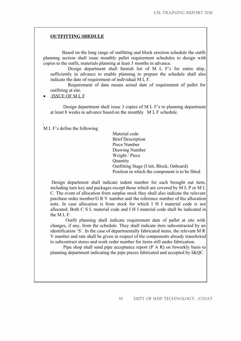
7/23/2019 CSL FINAL_3
http://slidepdf.com/reader/full/csl-final3 91/132
OUTFITTING SHEDULE
Based on the long range of outfitting and block erection schedule the outfit
planning section shall issue monthly pallet requirement schedules to design withcopies to the outfit, materials planning at least 3 months in advance.
Design department shall furnish list of M L F’s for entire ship,
sufficiently in advance to enable planning to prepare the schedule shall also
indicate the date of requirement of individual M L F.Requirement of data means actual date of requirement of pallet for
outfitting at site.
• ISSUE OF M L F
Design department shall issue 3 copies of M L F’s to planning department
at least 8 weeks in advance based on the monthly M L F schedule.
.
M L F’s define the following
Material codeBrief Description
Piece Number
Drawing Number
Weight / PieceQuantity
Outfitting Stage (Unit, Block, Onboard)
Position in which the component is to be fitted
Design department shall indicate indent number for each brought out item,
including turn key and packages except those which are covered by M L P or M LC. The event of allocation from surplus stock they shall also indicate the relevant
purchase order number/G R V number and the reference number of the allocation
note. In case allocation is from stock for which I H I material code is notallocated. Both C S L material code and I H I material code shall be indicated in
the M L F.
Outfit planning shall indicate requirement date of pallet at site with
changes, if any, from the schedule. They shall indicate item subcontracted by anidentification ‘S’. In the case of departmentally fabricated items, the relevant M R
V number and rate shall be given in respect of the components already transferred
to subcontract stores and work order number for items still under fabrication.Pipe shop shall send pipe acceptance report (P A R) on biweekly basis to
planning department indicating the pipe pieces fabricated and accepted by I&QC.
CSL TRAINING REPORT 2011
91 DEPT OF SHIP TECHNOLOGY , CUSAT
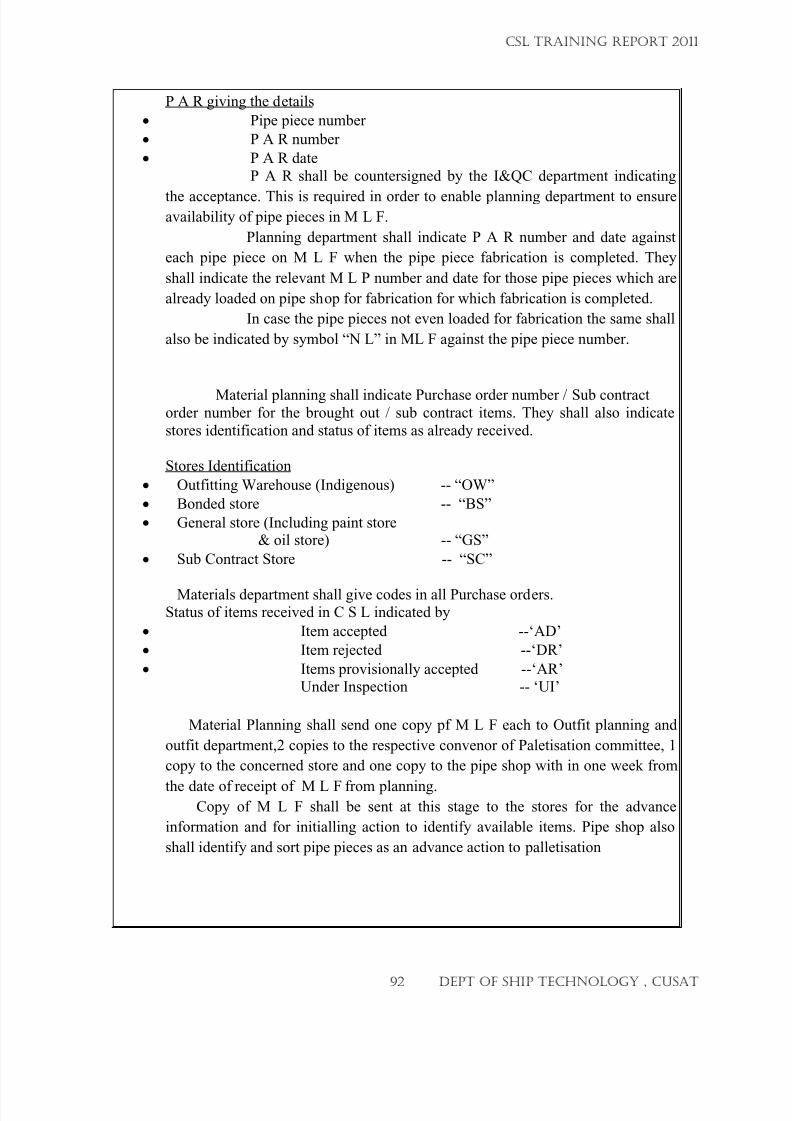
7/23/2019 CSL FINAL_3
http://slidepdf.com/reader/full/csl-final3 92/132
P A R giving the details
• Pipe piece number
• P A R number
• P A R date
P A R shall be countersigned by the I&QC department indicating
the acceptance. This is required in order to enable planning department to ensureavailability of pipe pieces in M L F.
Planning department shall indicate P A R number and date against
each pipe piece on M L F when the pipe piece fabrication is completed. They
shall indicate the relevant M L P number and date for those pipe pieces which are
already loaded on pipe shop for fabrication for which fabrication is completed.
In case the pipe pieces not even loaded for fabrication the same shall
also be indicated by symbol “N L” in ML F against the pipe piece number.
Material planning shall indicate Purchase order number / Sub contractorder number for the brought out / sub contract items. They shall also indicate
stores identification and status of items as already received.
Stores Identification
• Outfitting Warehouse (Indigenous) -- “OW”
• Bonded store -- “BS”
• General store (Including paint store
& oil store) -- “GS”
• Sub Contract Store -- “SC”
Materials department shall give codes in all Purchase orders.Status of items received in C S L indicated by
• Item accepted --‘AD’
• Item rejected --‘DR’
• Items provisionally accepted --‘AR’Under Inspection -- ‘UI’
Material Planning shall send one copy pf M L F each to Outfit planning and
outfit department,2 copies to the respective convenor of Paletisation committee, 1
copy to the concerned store and one copy to the pipe shop with in one week from
the date of receipt of M L F from planning.Copy of M L F shall be sent at this stage to the stores for the advance
information and for initialling action to identify available items. Pipe shop also
shall identify and sort pipe pieces as an advance action to palletisation
CSL TRAINING REPORT 2011
92 DEPT OF SHIP TECHNOLOGY , CUSAT
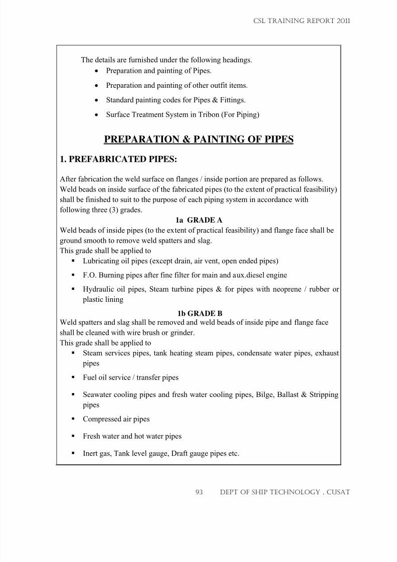
7/23/2019 CSL FINAL_3
http://slidepdf.com/reader/full/csl-final3 93/132
The details are furnished under the following headings.
• Preparation and painting of Pipes.
• Preparation and painting of other outfit items.
•
Standard painting codes for Pipes & Fittings.
• Surface Treatment System in Tribon (For Piping)
PREPARATION & PAINTING OF PIPES
1. PREFABRICATED PIPES:
After fabrication the weld surface on flanges / inside portion are prepared as follows.
Weld beads on inside surface of the fabricated pipes (to the extent of practical feasibility)
shall be finished to suit to the purpose of each piping system in accordance with
following three (3) grades.
1a GRADE A
Weld beads of inside pipes (to the extent of practical feasibility) and flange face shall be
ground smooth to remove weld spatters and slag.
This grade shall be applied to
Lubricating oil pipes (except drain, air vent, open ended pipes)
F.O. Burning pipes after fine filter for main and aux.diesel engine
Hydraulic oil pipes, Steam turbine pipes & for pipes with neoprene / rubber or
plastic lining
1b GRADE B Weld spatters and slag shall be removed and weld beads of inside pipe and flange face
shall be cleaned with wire brush or grinder.
This grade shall be applied to
Steam services pipes, tank heating steam pipes, condensate water pipes, exhaust
pipes
Fuel oil service / transfer pipes
Seawater cooling pipes and fresh water cooling pipes, Bilge, Ballast & Stripping pipes
Compressed air pipes
Fresh water and hot water pipes
Inert gas, Tank level gauge, Draft gauge pipes etc.
CSL TRAINING REPORT 2011
93 DEPT OF SHIP TECHNOLOGY , CUSAT
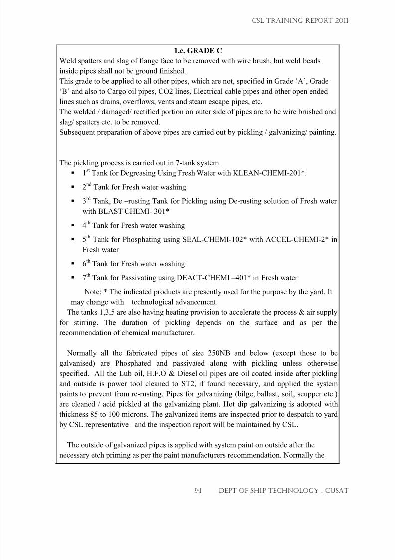
7/23/2019 CSL FINAL_3
http://slidepdf.com/reader/full/csl-final3 94/132
1.c. GRADE C
Weld spatters and slag of flange face to be removed with wire brush, but weld beads
inside pipes shall not be ground finished.
This grade to be applied to all other pipes, which are not, specified in Grade ‘A’, Grade
‘B’ and also to Cargo oil pipes, CO2 lines, Electrical cable pipes and other open ended
lines such as drains, overflows, vents and steam escape pipes, etc.
The welded / damaged/ rectified portion on outer side of pipes are to be wire brushed and
slag/ spatters etc. to be removed.
Subsequent preparation of above pipes are carried out by pickling / galvanizing/ painting.
The pickling process is carried out in 7-tank system.
1
st Tank for Degreasing Using Fresh Water with KLEAN-CHEMI-201*.
2nd
Tank for Fresh water washing
3rd
Tank, De –rusting Tank for Pickling using De-rusting solution of Fresh water
with BLAST CHEMI- 301*
4th
Tank for Fresh water washing
5
th Tank for Phosphating using SEAL-CHEMI-102* with ACCEL-CHEMI-2* in
Fresh water
6th
Tank for Fresh water washing
7th
Tank for Passivating using DEACT-CHEMI –401* in Fresh water
Note: * The indicated products are presently used for the purpose by the yard. Itmay change with technological advancement.
The tanks 1,3,5 are also having heating provision to accelerate the process & air supply
for stirring. The duration of pickling depends on the surface and as per the
recommendation of chemical manufacturer.
Normally all the fabricated pipes of size 250NB and below (except those to be
galvanised) are Phosphated and passivated along with pickling unless otherwise
specified. All the Lub oil, H.F.O & Diesel oil pipes are oil coated inside after pickling
and outside is power tool cleaned to ST2, if found necessary, and applied the system
paints to prevent from re-rusting. Pipes for galvanizing (bilge, ballast, soil, scupper etc.)are cleaned / acid pickled at the galvanizing plant. Hot dip galvanizing is adopted with
thickness 85 to 100 microns. The galvanized items are inspected prior to despatch to yard
by CSL representative and the inspection report will be maintained by CSL.
The outside of galvanized pipes is applied with system paint on outside after the
necessary etch priming as per the paint manufacturers recommendation. Normally the
CSL TRAINING REPORT 2011
94 DEPT OF SHIP TECHNOLOGY , CUSAT
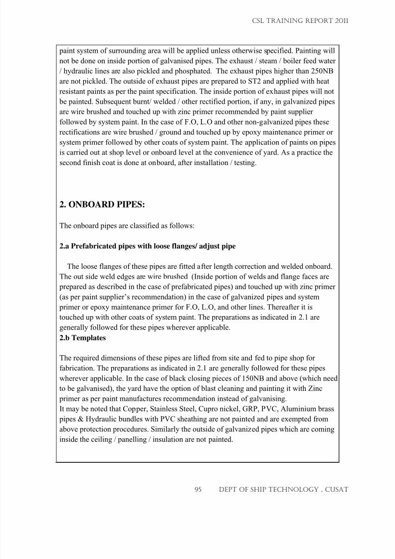
7/23/2019 CSL FINAL_3
http://slidepdf.com/reader/full/csl-final3 95/132
paint system of surrounding area will be applied unless otherwise specified. Painting will
not be done on inside portion of galvanised pipes. The exhaust / steam / boiler feed water
/ hydraulic lines are also pickled and phosphated. The exhaust pipes higher than 250NB
are not pickled. The outside of exhaust pipes are prepared to ST2 and applied with heat
resistant paints as per the paint specification. The inside portion of exhaust pipes will not
be painted. Subsequent burnt/ welded / other rectified portion, if any, in galvanized pipes
are wire brushed and touched up with zinc primer recommended by paint supplier
followed by system paint. In the case of F.O, L.O and other non-galvanized pipes these
rectifications are wire brushed / ground and touched up by epoxy maintenance primer or
system primer followed by other coats of system paint. The application of paints on pipes
is carried out at shop level or onboard level at the convenience of yard. As a practice the
second finish coat is done at onboard, after installation / testing.
2. ONBOARD PIPES:
The onboard pipes are classified as follows:
2.a Prefabricated pipes with loose flanges/ adjust pipe
The loose flanges of these pipes are fitted after length correction and welded onboard.
The out side weld edges are wire brushed (Inside portion of welds and flange faces are
prepared as described in the case of prefabricated pipes) and touched up with zinc primer
(as per paint supplier’s recommendation) in the case of galvanized pipes and system
primer or epoxy maintenance primer for F.O, L.O, and other lines. Thereafter it is
touched up with other coats of system paint. The preparations as indicated in 2.1 are
generally followed for these pipes wherever applicable.
2.b Templates
The required dimensions of these pipes are lifted from site and fed to pipe shop for
fabrication. The preparations as indicated in 2.1 are generally followed for these pipes
wherever applicable. In the case of black closing pieces of 150NB and above (which need
to be galvanised), the yard have the option of blast cleaning and painting it with Zinc primer as per paint manufactures recommendation instead of galvanising.
It may be noted that Copper, Stainless Steel, Cupro nickel, GRP, PVC, Aluminium brass
pipes & Hydraulic bundles with PVC sheathing are not painted and are exempted from
above protection procedures. Similarly the outside of galvanized pipes which are coming
inside the ceiling / panelling / insulation are not painted.
CSL TRAINING REPORT 2011
95 DEPT OF SHIP TECHNOLOGY , CUSAT
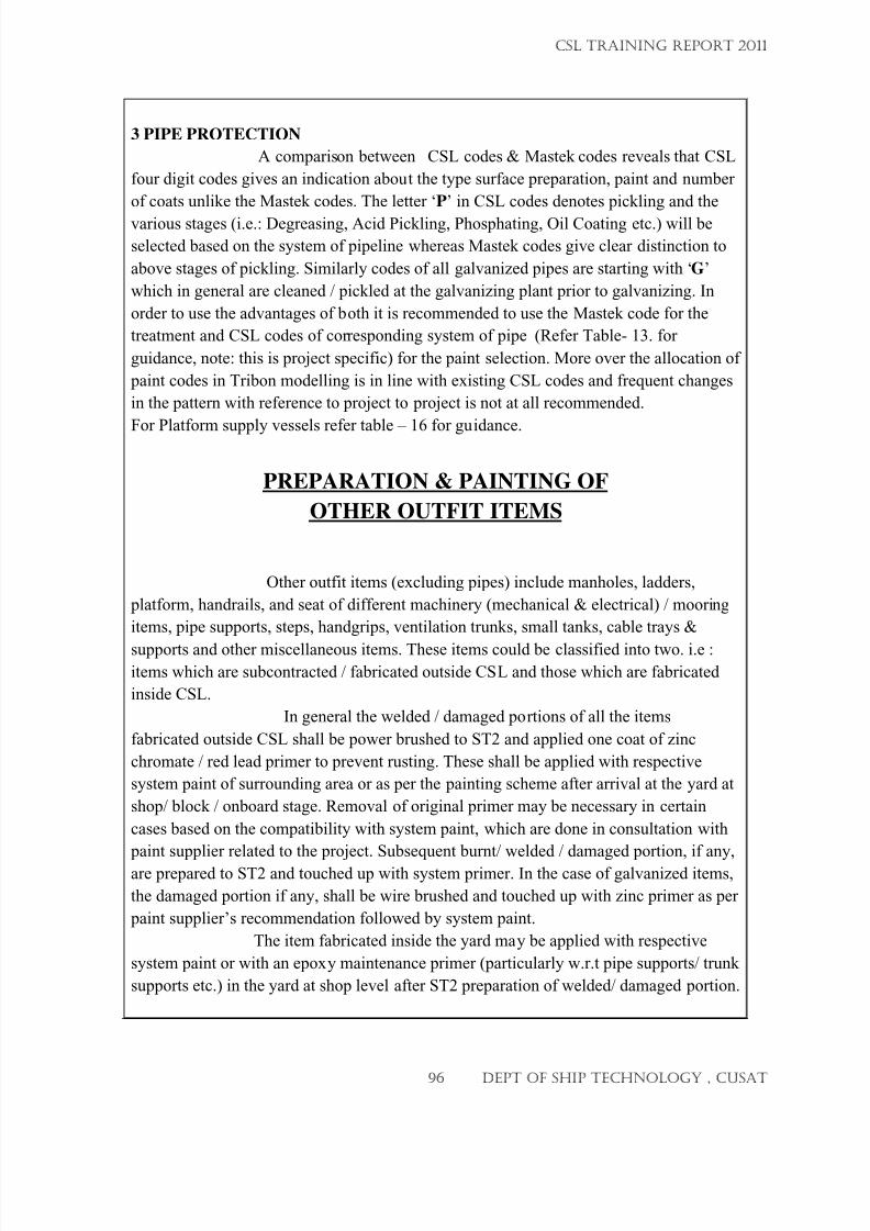
7/23/2019 CSL FINAL_3
http://slidepdf.com/reader/full/csl-final3 96/132
3 PIPE PROTECTION
A comparison between CSL codes & Mastek codes reveals that CSL
four digit codes gives an indication about the type surface preparation, paint and number
of coats unlike the Mastek codes. The letter ‘P’ in CSL codes denotes pickling and the
various stages (i.e.: Degreasing, Acid Pickling, Phosphating, Oil Coating etc.) will be
selected based on the system of pipeline whereas Mastek codes give clear distinction to
above stages of pickling. Similarly codes of all galvanized pipes are starting with ‘G’
which in general are cleaned / pickled at the galvanizing plant prior to galvanizing. In
order to use the advantages of both it is recommended to use the Mastek code for the
treatment and CSL codes of corresponding system of pipe (Refer Table- 13. for
guidance, note: this is project specific) for the paint selection. More over the allocation of
paint codes in Tribon modelling is in line with existing CSL codes and frequent changes
in the pattern with reference to project to project is not at all recommended.
For Platform supply vessels refer table – 16 for guidance.
PREPARATION & PAINTING OF
OTHER OUTFIT ITEMS
Other outfit items (excluding pipes) include manholes, ladders,
platform, handrails, and seat of different machinery (mechanical & electrical) / mooring
items, pipe supports, steps, handgrips, ventilation trunks, small tanks, cable trays &
supports and other miscellaneous items. These items could be classified into two. i.e :items which are subcontracted / fabricated outside CSL and those which are fabricated
inside CSL.
In general the welded / damaged portions of all the items
fabricated outside CSL shall be power brushed to ST2 and applied one coat of zinc
chromate / red lead primer to prevent rusting. These shall be applied with respective
system paint of surrounding area or as per the painting scheme after arrival at the yard at
shop/ block / onboard stage. Removal of original primer may be necessary in certain
cases based on the compatibility with system paint, which are done in consultation with
paint supplier related to the project. Subsequent burnt/ welded / damaged portion, if any,
are prepared to ST2 and touched up with system primer. In the case of galvanized items,
the damaged portion if any, shall be wire brushed and touched up with zinc primer as per
paint supplier’s recommendation followed by system paint.
The item fabricated inside the yard may be applied with respective
system paint or with an epoxy maintenance primer (particularly w.r.t pipe supports/ trunk
supports etc.) in the yard at shop level after ST2 preparation of welded/ damaged portion.
CSL TRAINING REPORT 2011
96 DEPT OF SHIP TECHNOLOGY , CUSAT
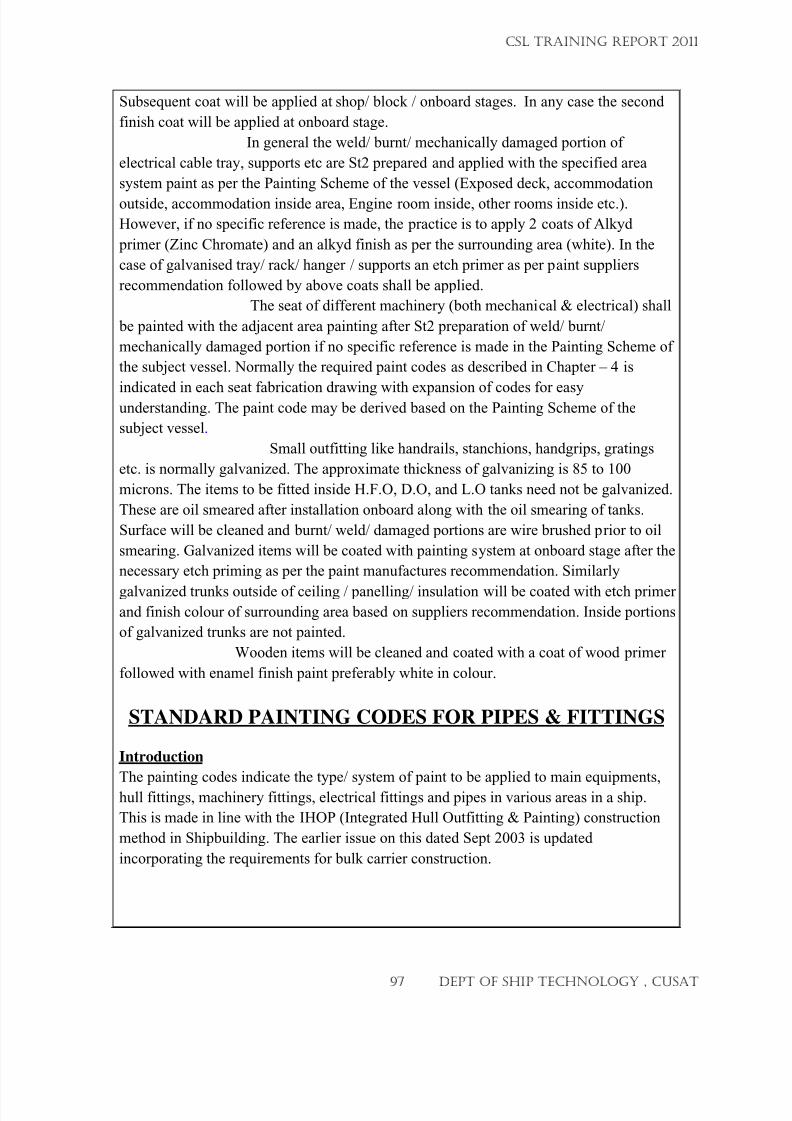
7/23/2019 CSL FINAL_3
http://slidepdf.com/reader/full/csl-final3 97/132
Subsequent coat will be applied at shop/ block / onboard stages. In any case the second
finish coat will be applied at onboard stage.
In general the weld/ burnt/ mechanically damaged portion of
electrical cable tray, supports etc are St2 prepared and applied with the specified area
system paint as per the Painting Scheme of the vessel (Exposed deck, accommodation
outside, accommodation inside area, Engine room inside, other rooms inside etc.).
However, if no specific reference is made, the practice is to apply 2 coats of Alkyd
primer (Zinc Chromate) and an alkyd finish as per the surrounding area (white). In the
case of galvanised tray/ rack/ hanger / supports an etch primer as per paint suppliers
recommendation followed by above coats shall be applied.
The seat of different machinery (both mechanical & electrical) shall
be painted with the adjacent area painting after St2 preparation of weld/ burnt/
mechanically damaged portion if no specific reference is made in the Painting Scheme of
the subject vessel. Normally the required paint codes as described in Chapter – 4 is
indicated in each seat fabrication drawing with expansion of codes for easyunderstanding. The paint code may be derived based on the Painting Scheme of the
subject vessel.
Small outfitting like handrails, stanchions, handgrips, gratings
etc. is normally galvanized. The approximate thickness of galvanizing is 85 to 100
microns. The items to be fitted inside H.F.O, D.O, and L.O tanks need not be galvanized.
These are oil smeared after installation onboard along with the oil smearing of tanks.
Surface will be cleaned and burnt/ weld/ damaged portions are wire brushed prior to oil
smearing. Galvanized items will be coated with painting system at onboard stage after the
necessary etch priming as per the paint manufactures recommendation. Similarly
galvanized trunks outside of ceiling / panelling/ insulation will be coated with etch primerand finish colour of surrounding area based on suppliers recommendation. Inside portions
of galvanized trunks are not painted.
Wooden items will be cleaned and coated with a coat of wood primer
followed with enamel finish paint preferably white in colour.
STANDARD PAINTING CODES FOR PIPES & FITTINGS
Introduction
The painting codes indicate the type/ system of paint to be applied to main equipments,
hull fittings, machinery fittings, electrical fittings and pipes in various areas in a ship.
This is made in line with the IHOP (Integrated Hull Outfitting & Painting) construction
method in Shipbuilding. The earlier issue on this dated Sept 2003 is updated
incorporating the requirements for bulk carrier construction.
CSL TRAINING REPORT 2011
97 DEPT OF SHIP TECHNOLOGY , CUSAT
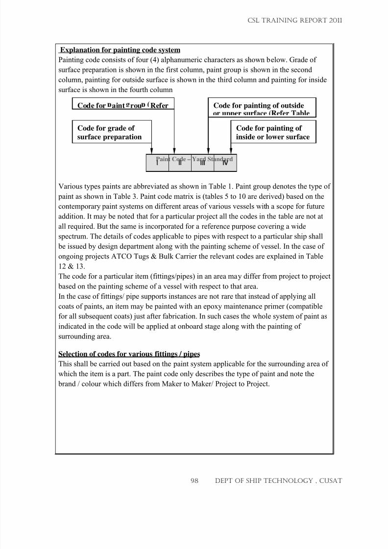
7/23/2019 CSL FINAL_3
http://slidepdf.com/reader/full/csl-final3 98/132
Explanation for painting code system
Painting code consists of four (4) alphanumeric characters as shown below. Grade of
surface preparation is shown in the first column, paint group is shown in the second
column, painting for outside surface is shown in the third column and painting for inside
surface is shown in the fourth column
Paint Code – Yard Standard
Various types paints are abbreviated as shown in Table 1. Paint group denotes the type of
paint as shown in Table 3. Paint code matrix is (tables 5 to 10 are derived) based on the
contemporary paint systems on different areas of various vessels with a scope for future
addition. It may be noted that for a particular project all the codes in the table are not at
all required. But the same is incorporated for a reference purpose covering a wide
spectrum. The details of codes applicable to pipes with respect to a particular ship shall
be issued by design department along with the painting scheme of vessel. In the case of
ongoing projects ATCO Tugs & Bulk Carrier the relevant codes are explained in Table
12 & 13.
The code for a particular item (fittings/pipes) in an area may differ from project to project
based on the painting scheme of a vessel with respect to that area.In the case of fittings/ pipe supports instances are not rare that instead of applying all
coats of paints, an item may be painted with an epoxy maintenance primer (compatible
for all subsequent coats) just after fabrication. In such cases the whole system of paint as
indicated in the code will be applied at onboard stage along with the painting of
surrounding area.
Selection of codes for various fittings / pipes
This shall be carried out based on the paint system applicable for the surrounding area of
which the item is a part. The paint code only describes the type of paint and note the
brand / colour which differs from Maker to Maker/ Project to Project.
Code for grade of
surface preparation
V
Code for aint rou Refer
Code for painting of
inside or lower surface
Code for painting of outside
CSL TRAINING REPORT 2011
98 DEPT OF SHIP TECHNOLOGY , CUSAT
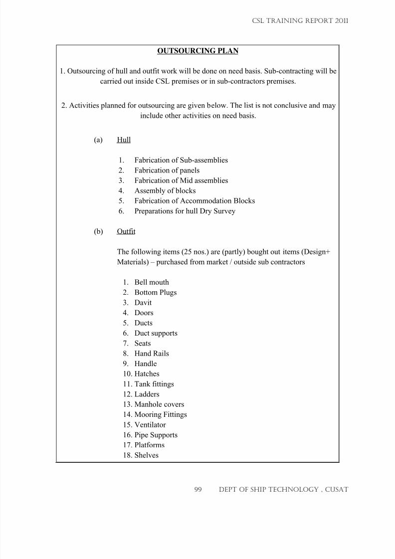
7/23/2019 CSL FINAL_3
http://slidepdf.com/reader/full/csl-final3 99/132
OUTSOURCING PLAN
1. Outsourcing of hull and outfit work will be done on need basis. Sub-contracting will be
carried out inside CSL premises or in sub-contractors premises.
2. Activities planned for outsourcing are given below. The list is not conclusive and may
include other activities on need basis.
(a) Hull
1. Fabrication of Sub-assemblies
2. Fabrication of panels
3. Fabrication of Mid assemblies
4. Assembly of blocks
5.
Fabrication of Accommodation Blocks
6. Preparations for hull Dry Survey
(b) Outfit
The following items (25 nos.) are (partly) bought out items (Design+
Materials) – purchased from market / outside sub contractors
1. Bell mouth
2.
Bottom Plugs3. Davit
4. Doors
5. Ducts
6. Duct supports
7. Seats
8. Hand Rails
9. Handle
10. Hatches
11. Tank fittings
12.
Ladders
13. Manhole covers
14. Mooring Fittings
15. Ventilator
16. Pipe Supports
17. Platforms
18. Shelves
CSL TRAINING REPORT 2011
99 DEPT OF SHIP TECHNOLOGY , CUSAT
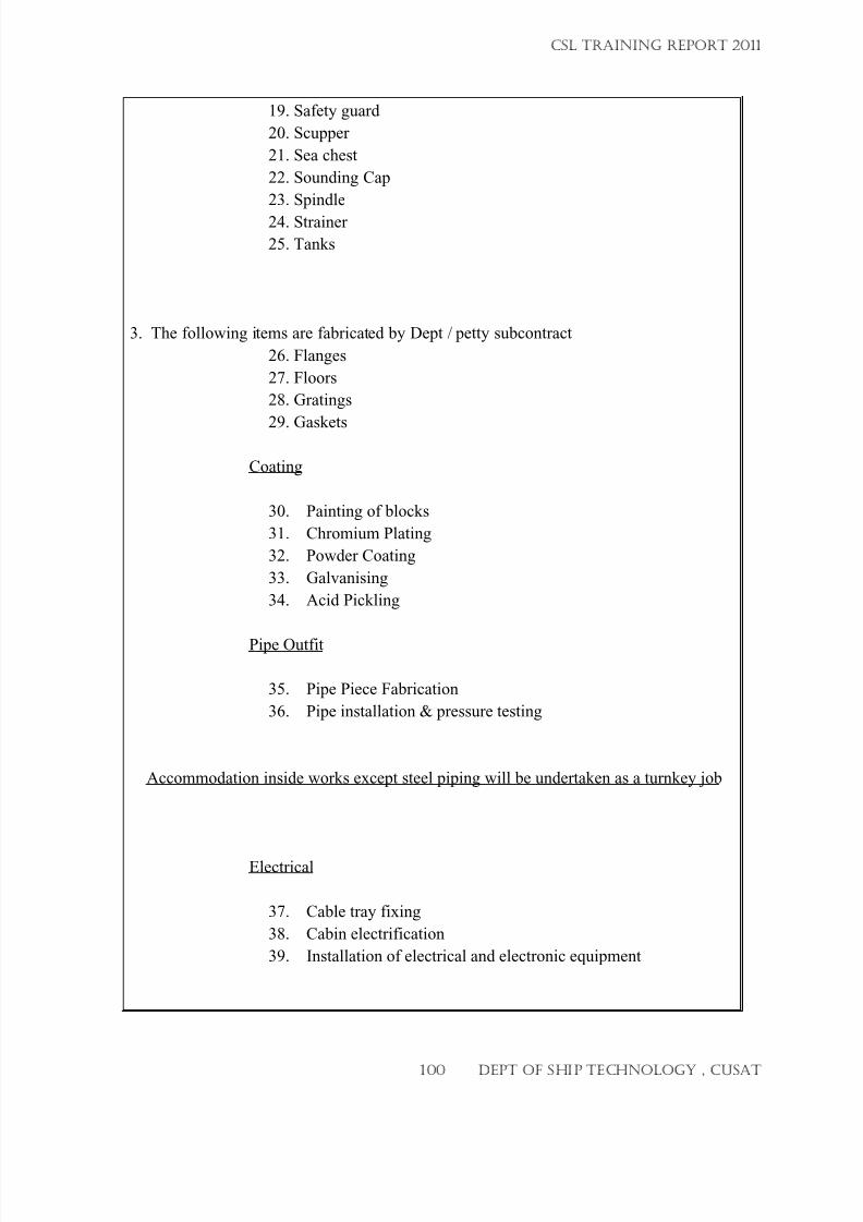
7/23/2019 CSL FINAL_3
http://slidepdf.com/reader/full/csl-final3 100/132
19. Safety guard
20. Scupper
21. Sea chest
22. Sounding Cap
23. Spindle
24.
Strainer
25. Tanks
3. The following items are fabricated by Dept / petty subcontract
26. Flanges
27. Floors
28. Gratings
29.
Gaskets
Coating
30. Painting of blocks
31. Chromium Plating
32. Powder Coating
33. Galvanising
34. Acid Pickling
Pipe Outfit
35. Pipe Piece Fabrication
36. Pipe installation & pressure testing
Accommodation inside works except steel piping will be undertaken as a turnkey job
Electrical
37. Cable tray fixing
38. Cabin electrification
39. Installation of electrical and electronic equipment
CSL TRAINING REPORT 2011
100 DEPT OF SHIP TECHNOLOGY , CUSAT
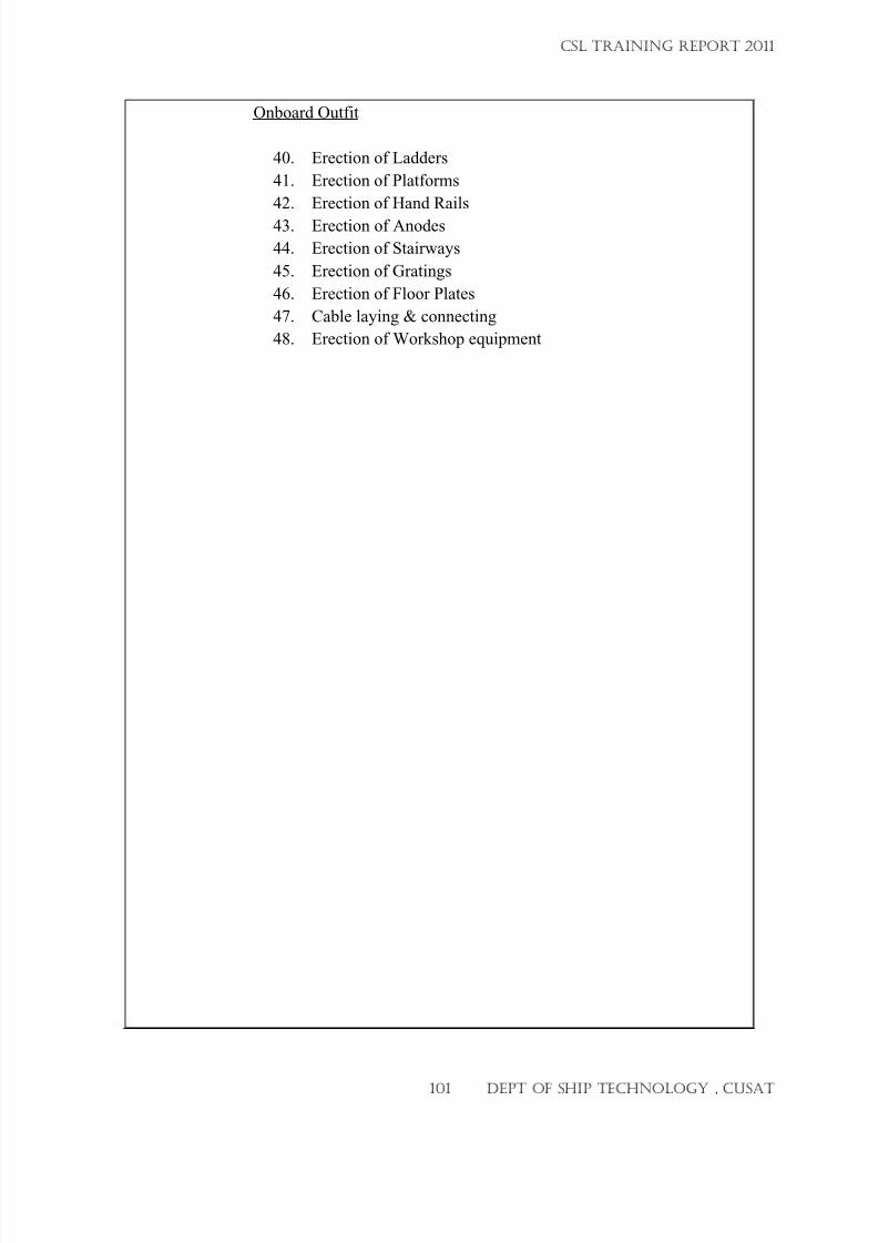
7/23/2019 CSL FINAL_3
http://slidepdf.com/reader/full/csl-final3 101/132
Onboard Outfit
40. Erection of Ladders
41. Erection of Platforms
42. Erection of Hand Rails
43.
Erection of Anodes
44. Erection of Stairways
45. Erection of Gratings
46. Erection of Floor Plates
47. Cable laying & connecting
48. Erection of Workshop equipment
CSL TRAINING REPORT 2011
101 DEPT OF SHIP TECHNOLOGY , CUSAT
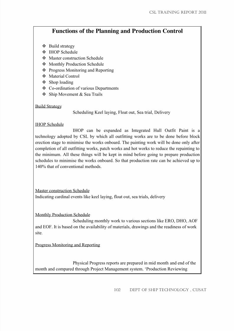
7/23/2019 CSL FINAL_3
http://slidepdf.com/reader/full/csl-final3 102/132
Functions of the Planning and Production Control
Build strategy
IHOP Schedule
Master construction Schedule Monthly Production Schedule
Progress Monitoring and Reporting
Material Control
Shop loading
Co-ordination of various Departments
Ship Movement & Sea Trails
Build Strategy
Scheduling Keel laying, Float out, Sea trial, Delivery
IHOP Schedule
IHOP can be expanded as Integrated Hull Outfit Paint is a
technology adopted by CSL by which all outfitting works are to be done before block
erection stage to minimise the works onboard. The painting work will be done only after
completion of all outfitting works, patch works and hot works to reduce the repainting to
the minimum. All these things will be kept in mind before going to prepare production
schedules to minimise the works onboard. So that production rate can be achieved up to
140% that of conventional methods.
Master construction Schedule
Indicating cardinal events like keel laying, float out, sea trials, delivery
Monthly Production Schedule
Scheduling monthly work to various sections like ERO, DHO, AOF
and EOF. It is based on the availability of materials, drawings and the readiness of work
site.
Progress Monitoring and Reporting
Physical Progress reports are prepared in mid month and end of the
month and compared through Project Management system. ‘Production Reviewing
CSL TRAINING REPORT 2011
102 DEPT OF SHIP TECHNOLOGY , CUSAT
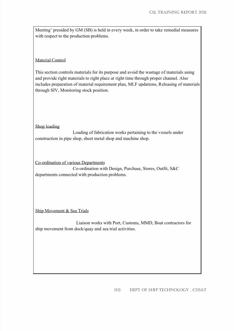
7/23/2019 CSL FINAL_3
http://slidepdf.com/reader/full/csl-final3 103/132
Meeting’ presided by GM (SB) is held in every week, in order to take remedial measures
with respect to the production problems.
Material Control
This section controls materials for its purpose and avoid the wastage of materials using
and provide right materials to right place at right time through proper channel. Also
includes preparation of material requirement plan, MLF updations, Releasing of materials
through SIV, Monitoring stock position.
Shop loading
Loading of fabrication works pertaining to the vessels under
construction in pipe shop, sheet metal shop and machine shop.
Co-ordination of various Departments
Co-ordination with Design, Purchase, Stores, Outfit, S&C
departments connected with production problems.
Ship Movement & Sea Trials
Liaison works with Port, Customs, MMD, Boat contractors for
ship movement from dock/quay and sea trial activities.
CSL TRAINING REPORT 2011
103 DEPT OF SHIP TECHNOLOGY , CUSAT
7/23/2019 CSL FINAL_3
http://slidepdf.com/reader/full/csl-final3 104/132
SHIP DESIGN DEPTARTMENT(01/06/2011 – 10/06/2011)
CSL TRAINING REPORT 2011
104 DEPT OF SHIP TECHNOLOGY , CUSAT
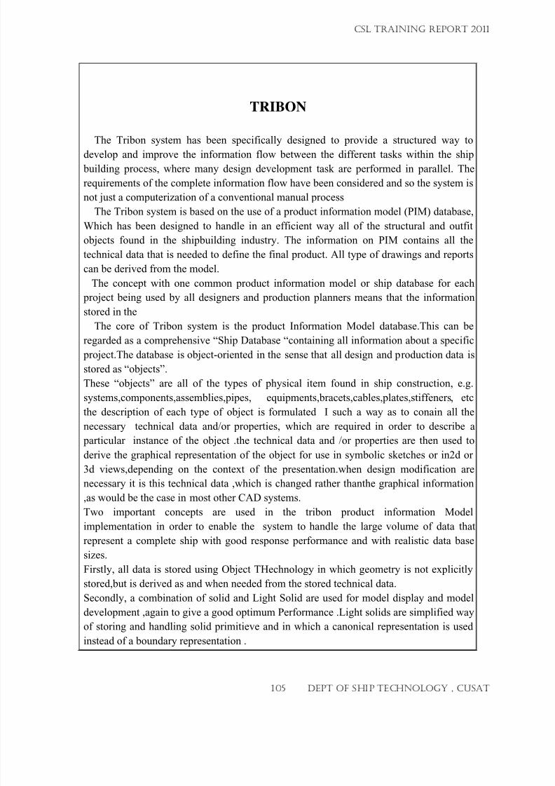
7/23/2019 CSL FINAL_3
http://slidepdf.com/reader/full/csl-final3 105/132
TRIBON
The Tribon system has been specifically designed to provide a structured way to
develop and improve the information flow between the different tasks within the ship
building process, where many design development task are performed in parallel. The
requirements of the complete information flow have been considered and so the system is
not just a computerization of a conventional manual process
The Tribon system is based on the use of a product information model (PIM) database,
Which has been designed to handle in an efficient way all of the structural and outfit
objects found in the shipbuilding industry. The information on PIM contains all the
technical data that is needed to define the final product. All type of drawings and reports
can be derived from the model.
The concept with one common product information model or ship database for each
project being used by all designers and production planners means that the information
stored in the
The core of Tribon system is the product Information Model database.This can be
regarded as a comprehensive “Ship Database “containing all information about a specific
project.The database is object-oriented in the sense that all design and production data is
stored as “objects”.
These “objects” are all of the types of physical item found in ship construction, e.g.
systems,components,assemblies,pipes, equipments,bracets,cables,plates,stiffeners, etc
the description of each type of object is formulated I such a way as to conain all thenecessary technical data and/or properties, which are required in order to describe a
particular instance of the object .the technical data and /or properties are then used to
derive the graphical representation of the object for use in symbolic sketches or in2d or
3d views,depending on the context of the presentation.when design modification are
necessary it is this technical data ,which is changed rather thanthe graphical information
,as would be the case in most other CAD systems.
Two important concepts are used in the tribon product information Model
implementation in order to enable the system to handle the large volume of data that
represent a complete ship with good response performance and with realistic data base
sizes.
Firstly, all data is stored using Object THechnology in which geometry is not explicitly
stored,but is derived as and when needed from the stored technical data.
Secondly, a combination of solid and Light Solid are used for model display and model
development ,again to give a good optimum Performance .Light solids are simplified way
of storing and handling solid primitieve and in which a canonical representation is used
instead of a boundary representation .
CSL TRAINING REPORT 2011
105 DEPT OF SHIP TECHNOLOGY , CUSAT
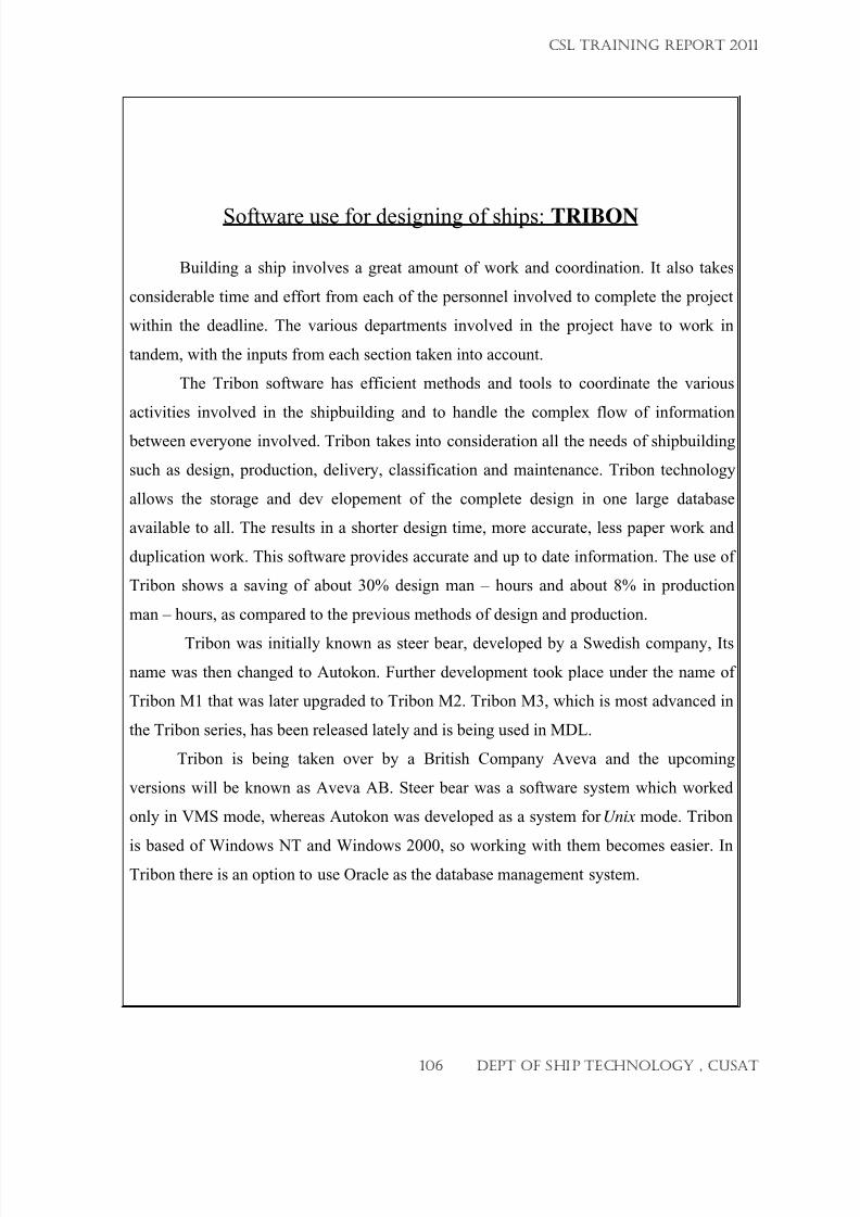
7/23/2019 CSL FINAL_3
http://slidepdf.com/reader/full/csl-final3 106/132
Software use for designing of ships: TRIBON
Building a ship involves a great amount of work and coordination. It also takes
considerable time and effort from each of the personnel involved to complete the project
within the deadline. The various departments involved in the project have to work in
tandem, with the inputs from each section taken into account.
The Tribon software has efficient methods and tools to coordinate the various
activities involved in the shipbuilding and to handle the complex flow of information
between everyone involved. Tribon takes into consideration all the needs of shipbuilding
such as design, production, delivery, classification and maintenance. Tribon technology
allows the storage and dev elopement of the complete design in one large database
available to all. The results in a shorter design time, more accurate, less paper work and
duplication work. This software provides accurate and up to date information. The use of
Tribon shows a saving of about 30% design man – hours and about 8% in production
man – hours, as compared to the previous methods of design and production.
Tribon was initially known as steer bear, developed by a Swedish company, Its
name was then changed to Autokon. Further development took place under the name of
Tribon M1 that was later upgraded to Tribon M2. Tribon M3, which is most advanced in
the Tribon series, has been released lately and is being used in MDL.
Tribon is being taken over by a British Company Aveva and the upcoming
versions will be known as Aveva AB. Steer bear was a software system which worked
only in VMS mode, whereas Autokon was developed as a system for Unix mode. Tribon
is based of Windows NT and Windows 2000, so working with them becomes easier. InTribon there is an option to use Oracle as the database management system.
CSL TRAINING REPORT 2011
106 DEPT OF SHIP TECHNOLOGY , CUSAT
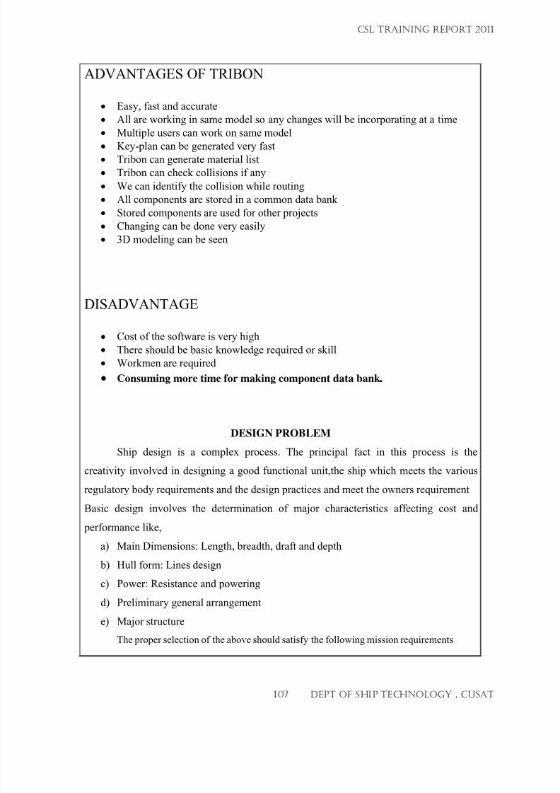
7/23/2019 CSL FINAL_3
http://slidepdf.com/reader/full/csl-final3 107/132
ADVANTAGES OF TRIBON
• Easy, fast and accurate
• All are working in same model so any changes will be incorporating at a time
• Multiple users can work on same model
•
Key-plan can be generated very fast
• Tribon can generate material list
• Tribon can check collisions if any
• We can identify the collision while routing
• All components are stored in a common data bank
• Stored components are used for other projects
• Changing can be done very easily
• 3D modeling can be seen
DISADVANTAGE
• Cost of the software is very high
• There should be basic knowledge required or skill
• Workmen are required
• Consuming more time for making component data bank.
DESIGN PROBLEM
Ship design is a complex process. The principal fact in this process is the
creativity involved in designing a good functional unit,the ship which meets the various
regulatory body requirements and the design practices and meet the owners requirement
Basic design involves the determination of major characteristics affecting cost and
performance like,
a) Main Dimensions: Length, breadth, draft and depth
b) Hull form: Lines design
c) Power: Resistance and powering
d) Preliminary general arrangement
e) Major structure
The proper selection of the above should satisfy the following mission requirements
CSL TRAINING REPORT 2011
107 DEPT OF SHIP TECHNOLOGY , CUSAT
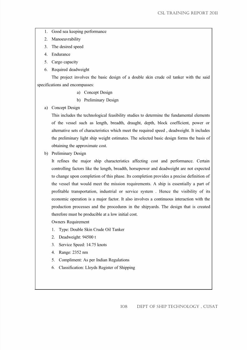
7/23/2019 CSL FINAL_3
http://slidepdf.com/reader/full/csl-final3 108/132
1. Good sea keeping performance
2. Manoeuvrability
3.
The desired speed
4. Endurance
5.
Cargo capacity
6. Required deadweight
The project involves the basic design of a double skin crude oil tanker with the said
specifications and encompasses:
a)
Concept Design
b) Preliminary Design
a) Concept Design
This includes the technological feasibility studies to determine the fundamental elements
of the vessel such as length, breadth, draught, depth, block coefficient, power or
alternative sets of characteristics which meet the required speed , deadweight. It includes
the preliminary light ship weight estimates. The selected basic design forms the basis of
obtaining the approximate cost.
b) Preliminary Design
It refines the major ship characteristics affecting cost and performance. Certain
controlling factors like the length, breadth, horsepower and deadweight are not expected
to change upon completion of this phase. Its completion provides a precise definition of
the vessel that would meet the mission requirements. A ship is essentially a part of
profitable transportation, industrial or service system . Hence the visibility of its
economic operation is a major factor. It also involves a continuous interaction with the
production processes and the procedures in the shipyards. The design that is created
therefore must be producible at a low initial cost.
Owners Requirement
1. Type: Double Skin Crude Oil Tanker
2. Deadweight: 94500 t
3.
Service Speed: 14.75 knots
4. Range: 2352 nm
5.
Compliment: As per Indian Regulations
6. Classification: Lloyds Register of Shipping
CSL TRAINING REPORT 2011
108 DEPT OF SHIP TECHNOLOGY , CUSAT
7/23/2019 CSL FINAL_3
http://slidepdf.com/reader/full/csl-final3 109/132
CREW ACCOMMODATION
This Convention does not apply to—
(a) Vessels of less than 500 tons;
(b) Vessels primarily propelled by sail but having auxiliary engines;
(c) Vessels engaged in fishing or in whaling or in similar pursuits;
(d) Tugs.
CREW ACCOMMODATION REQUIREMENTS
1. Ensure adequate security, protection against weather and sea, and insulation from heat
or cold, undue noise
2. No direct openings into sleeping rooms from spaces for cargo and machinery or from
galleys, lamp and paint rooms or from engine, deck and other bulk storerooms, drying
rooms, communal wash places or water closets
3. External bulkheads of sleeping rooms and mess rooms shall be adequately insulated.
4. Sleeping rooms, mess rooms, recreation rooms and alley-ways in the crew
accommodation space shall be adequately insulated to prevent condensation or
overheating.
5. Sufficient drainage shall be provided.
Ventilation
1. Sleeping rooms and mess rooms shall be adequately ventilated.
2. The system of ventilation shall be controlled so as to maintain the air in a satisfactory
condition
3. Persian Gulf equipped with both mechanical means of ventilation and electric fans:
CSL TRAINING REPORT 2011
109 DEPT OF SHIP TECHNOLOGY , CUSAT
7/23/2019 CSL FINAL_3
http://slidepdf.com/reader/full/csl-final3 110/132
4. Ships engaged outside the tropics equipped with either mechanical means of
ventilation or electric fans.
Heating system
1. An adequate system of heating the crew accommodation shall be provided except inships engaged exclusively in voyages in the tropics and the Persian Gulf.
2. The heating system shall be capable of maintaining the temperature in crew
accommodation at a satisfactory level under normal conditions of weather and climate.
Lighting
1. The minimum standard for natural lighting in living rooms shall be such as to permit a
person with a normal vision to read on a clear day an ordinary newspaper in any part of
the space available for free movement.
2. In sleeping rooms an electric reading lamp shall be installed at the head of each berth.
OTHERS
1. The clear head room in crew sleeping rooms shall not be less than 190 cm..
3. Berths shall not be placed side by side
4. The lower berth in a double tier shall be not less than 30 cm above the floor;
5. The minimum inside dimensions of a berth shall be 190 cm. by 68 cm..
6. separate mess room accommodation shall be provided for--
(a) master and officers;
(b) petty officers and other ratings.
7. Mess rooms shall be located close as practicable to the galley.
8. Recreation accommodation, conveniently situated and appropriately furnished, shall be
provided for officers
9. Sanitary accommodation, including wash basins and tub and/or shower baths, shall be
provided in all ships.
CSL TRAINING REPORT 2011
110 DEPT OF SHIP TECHNOLOGY , CUSAT
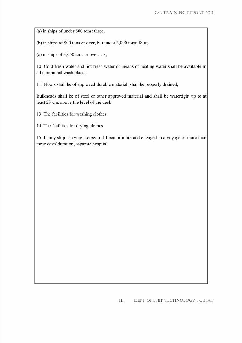
7/23/2019 CSL FINAL_3
http://slidepdf.com/reader/full/csl-final3 111/132
(a) in ships of under 800 tons: three;
(b) in ships of 800 tons or over, but under 3,000 tons: four;
(c) in ships of 3,000 tons or over: six;
10. Cold fresh water and hot fresh water or means of heating water shall be available in
all communal wash places.
11. Floors shall be of approved durable material, shall be properly drained;
Bulkheads shall be of steel or other approved material and shall be watertight up to at
least 23 cm. above the level of the deck;
13. The facilities for washing clothes
14. The facilities for drying clothes
15. In any ship carrying a crew of fifteen or more and engaged in a voyage of more than
three days' duration, separate hospital
CSL TRAINING REPORT 2011
111 DEPT OF SHIP TECHNOLOGY , CUSAT
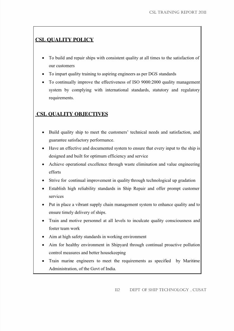
7/23/2019 CSL FINAL_3
http://slidepdf.com/reader/full/csl-final3 112/132
CSL QUALITY POLICY
•
To build and repair ships with consistent quality at all times to the satisfaction of
our customers
• To impart quality training to aspiring engineers as per DGS standards
• To continually improve the effectiveness of ISO 9000:2000 quality management
system by complying with international standards, statutory and regulatory
requirements.
CSL QUALITY OBJECTIVES
• Build quality ship to meet the customers’ technical needs and satisfaction, and
guarantee satisfactory performance.
• Have an effective and documented system to ensure that every input to the ship is
designed and built for optimum efficiency and service
• Achieve operational excellence through waste elimination and value engineering
efforts• Strive for continual improvement in quality through technological up gradation
• Establish high reliability standards in Ship Repair and offer prompt customer
services
• Put in place a vibrant supply chain management system to enhance quality and to
ensure timely delivery of ships.
• Train and motive personnel at all levels to inculcate quality consciousness and
foster team work
• Aim at high safety standards in working environment
• Aim for healthy environment in Shipyard through continual proactive pollution
control measures and better housekeeping
• Train marine engineers to meet the requirements as specified by Maritime
Administration, of the Govt of India.
CSL TRAINING REPORT 2011
112 DEPT OF SHIP TECHNOLOGY , CUSAT
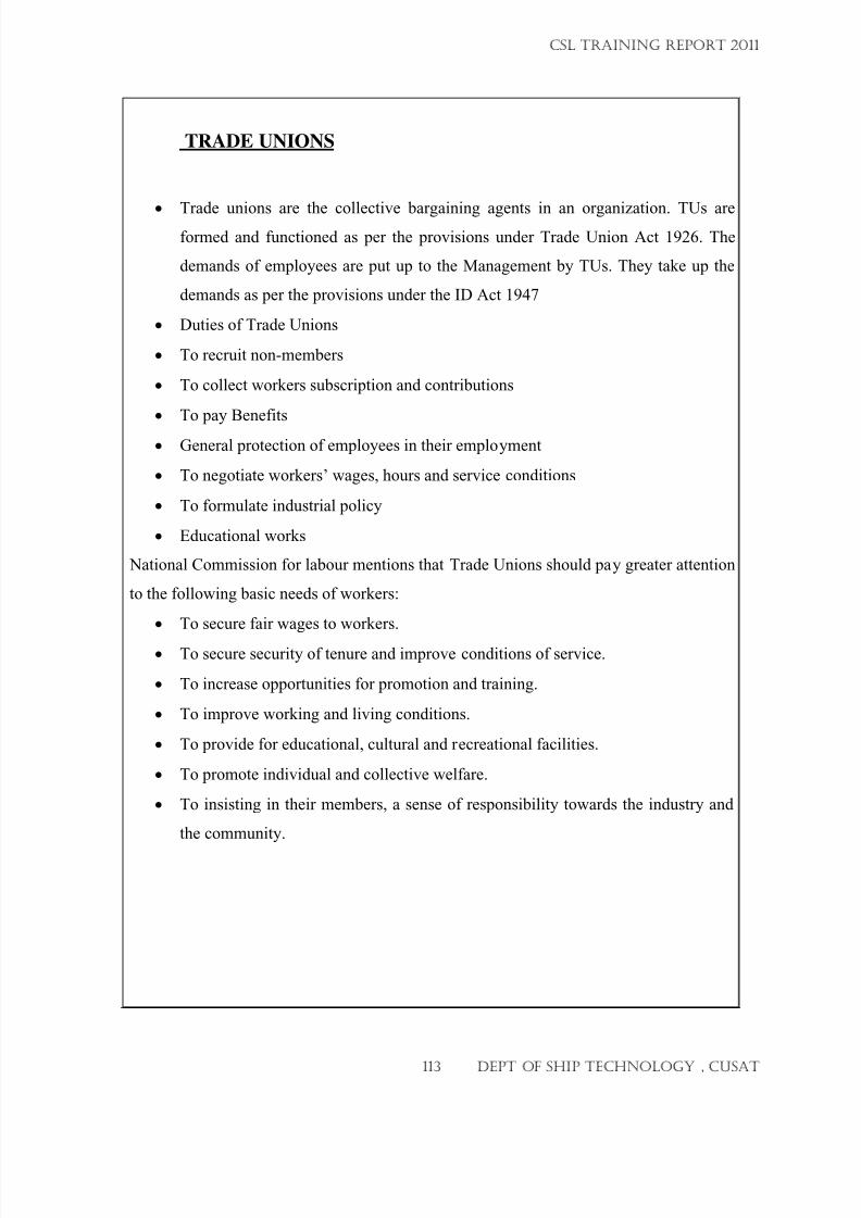
7/23/2019 CSL FINAL_3
http://slidepdf.com/reader/full/csl-final3 113/132
TRADE UNIONS
• Trade unions are the collective bargaining agents in an organization. TUs areformed and functioned as per the provisions under Trade Union Act 1926. The
demands of employees are put up to the Management by TUs. They take up the
demands as per the provisions under the ID Act 1947
• Duties of Trade Unions
• To recruit non-members
• To collect workers subscription and contributions
• To pay Benefits
• General protection of employees in their employment
• To negotiate workers’ wages, hours and service conditions
• To formulate industrial policy
• Educational works
National Commission for labour mentions that Trade Unions should pay greater attention
to the following basic needs of workers:
• To secure fair wages to workers.
• To secure security of tenure and improve conditions of service.
• To increase opportunities for promotion and training.
• To improve working and living conditions.
• To provide for educational, cultural and recreational facilities.
• To promote individual and collective welfare.
• To insisting in their members, a sense of responsibility towards the industry and
the community.
CSL TRAINING REPORT 2011
113 DEPT OF SHIP TECHNOLOGY , CUSAT
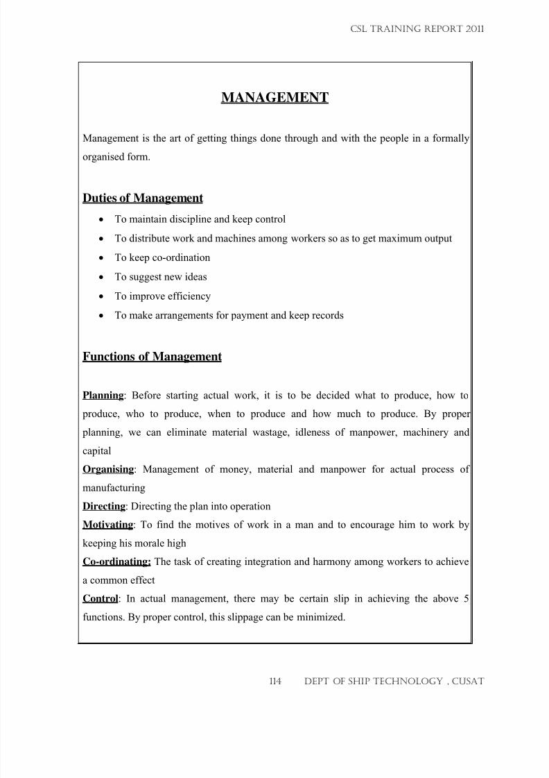
7/23/2019 CSL FINAL_3
http://slidepdf.com/reader/full/csl-final3 114/132
MANAGEMENT
Management is the art of getting things done through and with the people in a formally
organised form.
Duties of Management
• To maintain discipline and keep control
• To distribute work and machines among workers so as to get maximum output
• To keep co-ordination
•
To suggest new ideas
• To improve efficiency
• To make arrangements for payment and keep records
Functions of Management
Planning: Before starting actual work, it is to be decided what to produce, how to
produce, who to produce, when to produce and how much to produce. By proper
planning, we can eliminate material wastage, idleness of manpower, machinery and
capital
Organising: Management of money, material and manpower for actual process of
manufacturing
Directing: Directing the plan into operation
Motivating: To find the motives of work in a man and to encourage him to work by
keeping his morale highCo-ordinating: The task of creating integration and harmony among workers to achieve
a common effect
Control: In actual management, there may be certain slip in achieving the above 5
functions. By proper control, this slippage can be minimized.
CSL TRAINING REPORT 2011
114 DEPT OF SHIP TECHNOLOGY , CUSAT
7/23/2019 CSL FINAL_3
http://slidepdf.com/reader/full/csl-final3 115/132
WORKERS PARTICIPATION IN MANAGEMENT
This is a modern concept evolved by Govt of India. A law was enacted in 1975 on this.
As per this law, equal participation is ensured for workers and managemet representativesin some councils formed for the benefit of both employees and Company. Some such
councils are:
• Joint Council
• Shop Council
• Quality Circle
• DBF Trust
• PF Trust
• Employees Canteen
• Recreation Club
• Housing Society
• Consumer Society
• Suggestion Scheme
LEADERSHIP CHARACTERISTICS
Leadership is the skill of getting the desired action, voluntarily and without force from
the followers.
Leadership Characteristics:
• Intelligence and technical knowledge
• Communicative skill
• Objectivity
• Knowledge of work
• Human Relation
• Self Confidence & will power
• Empathy
• Sense of Responsibility & Humour
• Vision & foresight
• Optimism
CSL TRAINING REPORT 2011
115 DEPT OF SHIP TECHNOLOGY , CUSAT
7/23/2019 CSL FINAL_3
http://slidepdf.com/reader/full/csl-final3 116/132
Ways to improve Supervisory skills
• Necessary freedom should be given to supervisors to utilize their delegation of
powers
• Bypassing in any way on supervisors should not be encouraged
• Convey Management policies and decisions, only upto supervisors
• Whenever a worker is promoted to supervisor:
• Training should be given to him including theory classes
• He should be transferred to some other dept to take action without considering
any personal relations
• Periodical orientation classes should be conducted to supervisors to educate them
on latest developments in Management policies and technology
DISCIPLINARY ACTION
Methods of correcting a worker who is not working as per the Standing Order:
• Friendly Approach
• Advise to improve
• Identify the problem and rectify
• Grievances, if any to be found out
•
Close supervision
• Reporting to the Higher Authorities
When a subordinate is seen having indulged in some action which is against the standing
orders, call him personally and advice of his duties and responsibilities. If he is found
repeating the same, give him a verbal warning that “If you are not ready to do your
duties, I will be compelled to take action against you”. Even after this, his dealings are
going on the same, report the matter to your higher authorities to take action.
CSL TRAINING REPORT 2011
116 DEPT OF SHIP TECHNOLOGY , CUSAT

7/23/2019 CSL FINAL_3
http://slidepdf.com/reader/full/csl-final3 117/132
Domestic Enquiry:
A report on misconduct reaches the Disciplinary authority
• DA conducts a preliminary enquiry regarding the complaint
• If a case is found prima facie, suggests for further actions
• If the gravity of the case is big, the accused shall be placed under suspension to
avoid indulging with the evidence
• A charge sheet is given to the accused mentioning the details of misconduct,
violation of clauses of provision number of the standing order and asks for a reply
within the specified period
• Reply is received from the accused, considered for any justification
• If the reply is found not satisfactory, a domestic enquiry is ordered by the DA,
citing the names of Enquiry Officer, Presenting Officer, Management witness etc.
• Enquiry Officer issues notices to both Presenting Officer and the Accused
mentioning date, time and venue of enquiry
• The accused person can seek help of an Assisting Employee to present for him in
enquiry
• Enquiry procedure: Presenting the case, examining the witness of both accused
and management, presenting documents, if any etc. The enquiry procedure will
come to and end in 3 to 4 sittings
• Enquiry Officer submits the report to the Disciplinary authority
• If the allegation is proved, the Disciplinary authority issues the punishment order,
and asks for the response of the accused
• After verifying the reply, DA finalises the penalty and recommend the Personnel
Dept for implementation of the punishment
•
Accused can move to the Appellate authority for further appeal
• Considering the appeal, the final punishment order is issued by Personnel Dept.
CSL TRAINING REPORT 2011
117 DEPT OF SHIP TECHNOLOGY , CUSAT
7/23/2019 CSL FINAL_3
http://slidepdf.com/reader/full/csl-final3 118/132
WORK STUDY
The object of work study is to determine the best method of performing an operation to
eliminate wastage and increase productivity. It is also used to determine the standard timethat should take by a qualified worker to perform the operation when working at normal
pace.
Work Study deals with problems as:
How should a job be done?
This is found out by Motion Study, Method Study or by Work Samplification
How much time a job should take?
This is found out by Time Study of Work Measurement
PERT (Programme Evaluation Review Technique)
PERT is a way of scheduling to minimize the production delay by coordinating
and synchronizing the various activities of overall job and expediting the completion of
the job. PERT is a method of scheduling and budgeting resources.
CPM
It is an activity oriented management technique for scheduling and controlling the
various activities of a project. The path along the network in which EARLIEST FINISH
and LATEST FINISH are equal is known as CRITICAL PATH and is represented by
double line or thick line. More attention is given to this path, because a slight delay in
this path will effect adversely on completion of the total project. In brief, CPM method is
the shotest path or critical path through which the completion of production can be
attained.
Comparison between CPM & PERT
Deterministee model - Model under risk
Takes account of time - Concerns with cost.
Activity oriented -Event oriented.
One time estimate -Three time estimate.
CSL TRAINING REPORT 2011
118 DEPT OF SHIP TECHNOLOGY , CUSAT
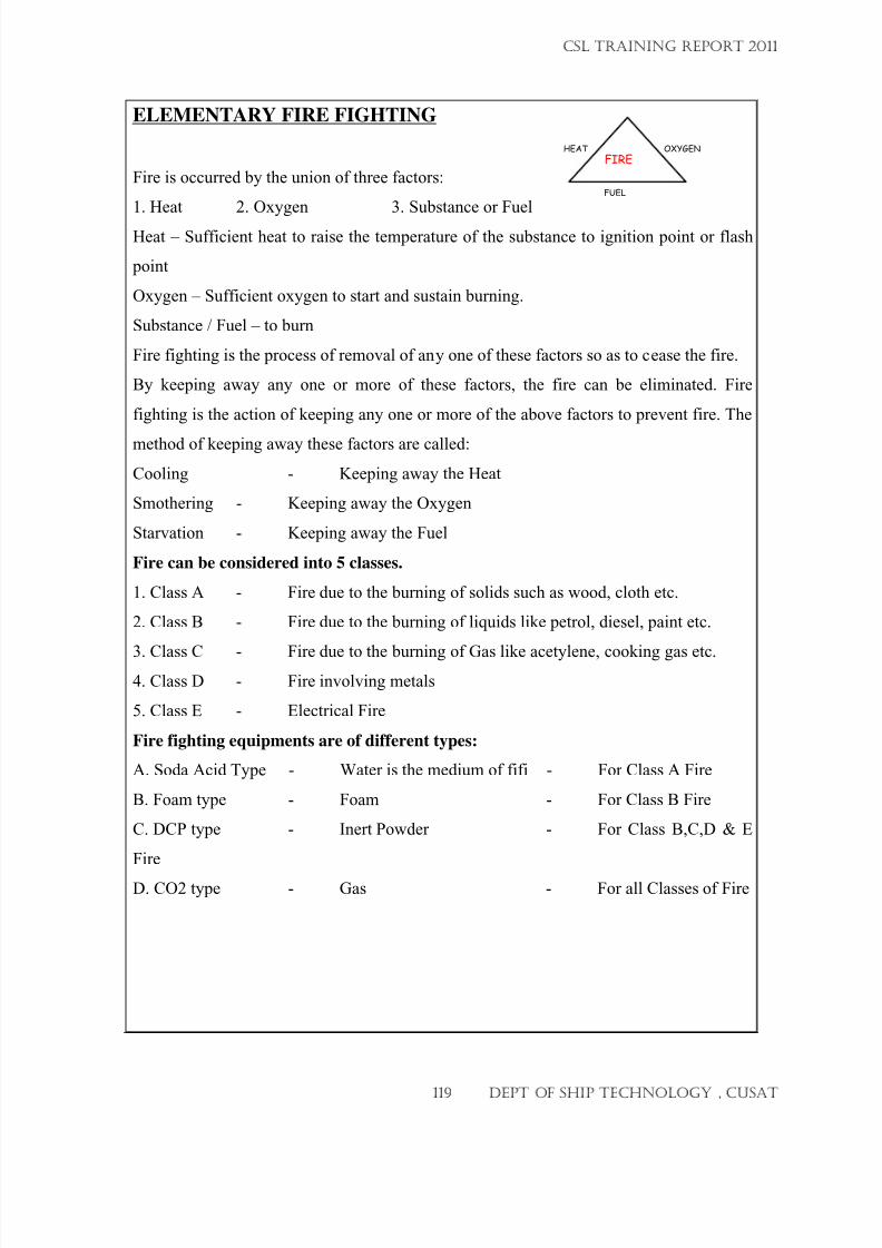
7/23/2019 CSL FINAL_3
http://slidepdf.com/reader/full/csl-final3 119/132
ELEMENTARY FIRE FIGHTING
Fire is occurred by the union of three factors:
1. Heat 2. Oxygen 3. Substance or Fuel
Heat – Sufficient heat to raise the temperature of the substance to ignition point or flash
point
Oxygen – Sufficient oxygen to start and sustain burning.
Substance / Fuel – to burn
Fire fighting is the process of removal of any one of these factors so as to cease the fire.
By keeping away any one or more of these factors, the fire can be eliminated. Fire
fighting is the action of keeping any one or more of the above factors to prevent fire. The
method of keeping away these factors are called:
Cooling - Keeping away the Heat
Smothering - Keeping away the Oxygen
Starvation - Keeping away the Fuel
Fire can be considered into 5 classes.
1. Class A - Fire due to the burning of solids such as wood, cloth etc.
2. Class B - Fire due to the burning of liquids like petrol, diesel, paint etc.
3. Class C - Fire due to the burning of Gas like acetylene, cooking gas etc.4. Class D - Fire involving metals
5. Class E - Electrical Fire
Fire fighting equipments are of different types:
A. Soda Acid Type - Water is the medium of fifi - For Class A Fire
B. Foam type - Foam - For Class B Fire
C. DCP type - Inert Powder - For Class B,C,D & E
Fire
D. CO2 type - Gas - For all Classes of Fire
FIREHEAT OXYGEN
FUEL
CSL TRAINING REPORT 2011
119 DEPT OF SHIP TECHNOLOGY , CUSAT
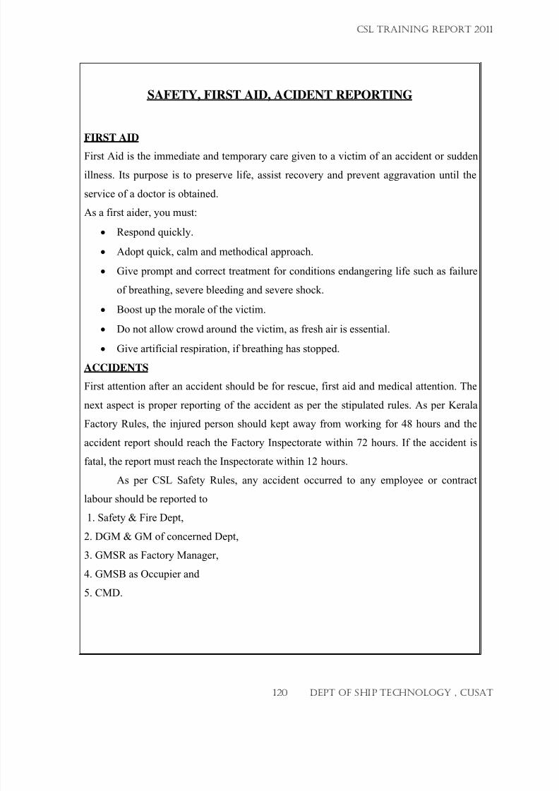
7/23/2019 CSL FINAL_3
http://slidepdf.com/reader/full/csl-final3 120/132
SAFETY, FIRST AID, ACIDENT REPORTING
FIRST AID
First Aid is the immediate and temporary care given to a victim of an accident or sudden
illness. Its purpose is to preserve life, assist recovery and prevent aggravation until the
service of a doctor is obtained.
As a first aider, you must:
• Respond quickly.
• Adopt quick, calm and methodical approach.
• Give prompt and correct treatment for conditions endangering life such as failure
of breathing, severe bleeding and severe shock.
• Boost up the morale of the victim.
• Do not allow crowd around the victim, as fresh air is essential.
• Give artificial respiration, if breathing has stopped.
ACCIDENTS
First attention after an accident should be for rescue, first aid and medical attention. The
next aspect is proper reporting of the accident as per the stipulated rules. As per Kerala
Factory Rules, the injured person should kept away from working for 48 hours and the
accident report should reach the Factory Inspectorate within 72 hours. If the accident is
fatal, the report must reach the Inspectorate within 12 hours.
As per CSL Safety Rules, any accident occurred to any employee or contract
labour should be reported to
1. Safety & Fire Dept,
2. DGM & GM of concerned Dept,
3. GMSR as Factory Manager,
4. GMSB as Occupier and
5. CMD.
CSL TRAINING REPORT 2011
120 DEPT OF SHIP TECHNOLOGY , CUSAT
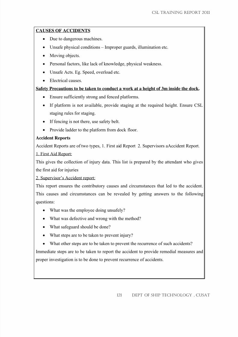
7/23/2019 CSL FINAL_3
http://slidepdf.com/reader/full/csl-final3 121/132
CAUSES OF ACCIDENTS
• Due to dangerous machines.
• Unsafe physical conditions – Improper guards, illumination etc.
• Moving objects.
• Personal factors, like lack of knowledge, physical weakness.
• Unsafe Acts. Eg. Speed, overload etc.
• Electrical causes.
Safety Precautions to be taken to conduct a work at a height of 3m inside the dock.
• Ensure sufficiently strong and fenced platforms.
• If platform is not available, provide staging at the required height. Ensure CSL
staging rules for staging.
• If fencing is not there, use safety belt.
• Provide ladder to the platform from dock floor.
Accident Reports
Accident Reports are of two types, 1. First aid Report 2. Supervisors aAccident Report.
1. First Aid Report:
This gives the collection of injury data. This list is prepared by the attendant who gives
the first aid for injuries
2. Supervisor’s Accident report:
This report ensures the contributory causes and circumstances that led to the accident.
This causes and circumstances can be revealed by getting answers to the following
questions:
• What was the employee doing unsafely?
• What was defective and wrong with the method?
• What safeguard should be done?
•
What steps are to be taken to prevent injury?
• What other steps are to be taken to prevent the recurrence of such accidents?
Immediate steps are to be taken to report the accident to provide remedial measures and
proper investigation is to be done to prevent recurrence of accidents.
CSL TRAINING REPORT 2011
121 DEPT OF SHIP TECHNOLOGY , CUSAT
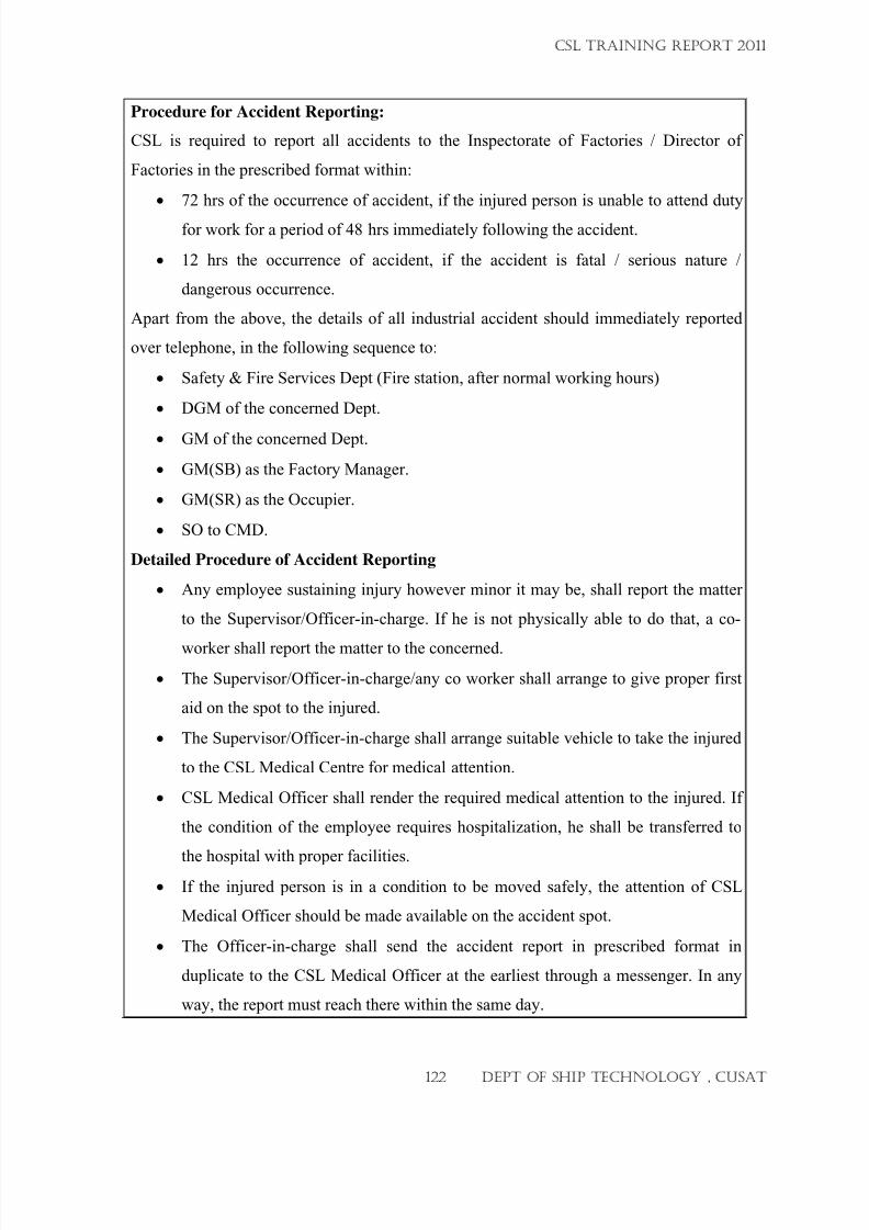
7/23/2019 CSL FINAL_3
http://slidepdf.com/reader/full/csl-final3 122/132
Procedure for Accident Reporting:
CSL is required to report all accidents to the Inspectorate of Factories / Director of
Factories in the prescribed format within:
• 72 hrs of the occurrence of accident, if the injured person is unable to attend duty
for work for a period of 48 hrs immediately following the accident.
• 12 hrs the occurrence of accident, if the accident is fatal / serious nature /
dangerous occurrence.
Apart from the above, the details of all industrial accident should immediately reported
over telephone, in the following sequence to:
• Safety & Fire Services Dept (Fire station, after normal working hours)
• DGM of the concerned Dept.
•
GM of the concerned Dept.
• GM(SB) as the Factory Manager.
• GM(SR) as the Occupier.
• SO to CMD.
Detailed Procedure of Accident Reporting
• Any employee sustaining injury however minor it may be, shall report the matter
to the Supervisor/Officer-in-charge. If he is not physically able to do that, a co-
worker shall report the matter to the concerned.
• The Supervisor/Officer-in-charge/any co worker shall arrange to give proper first
aid on the spot to the injured.
• The Supervisor/Officer-in-charge shall arrange suitable vehicle to take the injured
to the CSL Medical Centre for medical attention.
• CSL Medical Officer shall render the required medical attention to the injured. If
the condition of the employee requires hospitalization, he shall be transferred to
the hospital with proper facilities.• If the injured person is in a condition to be moved safely, the attention of CSL
Medical Officer should be made available on the accident spot.
• The Officer-in-charge shall send the accident report in prescribed format in
duplicate to the CSL Medical Officer at the earliest through a messenger. In any
way, the report must reach there within the same day.
CSL TRAINING REPORT 2011
122 DEPT OF SHIP TECHNOLOGY , CUSAT
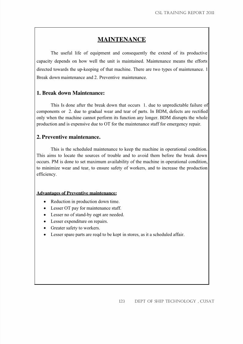
7/23/2019 CSL FINAL_3
http://slidepdf.com/reader/full/csl-final3 123/132
MAINTENANCE
The useful life of equipment and consequently the extend of its productive
capacity depends on how well the unit is maintained. Maintenance means the efforts
directed towards the up-keeping of that machine. There are two types of maintenance. 1
Break down maintenance and 2. Preventive maintenance.
1. Break down Maintenance:
This Is done after the break down that occurs 1. due to unpredictable failure of
components or 2. due to gradual wear and tear of parts. In BDM, defects are rectified
only when the machine cannot perform its function any longer. BDM disrupts the whole
production and is expensive due to OT for the maintenance staff for emergency repair.
2. Preventive maintenance.
This is the scheduled maintenance to keep the machine in operational condition.
This aims to locate the sources of trouble and to avoid them before the break down
occurs. PM is done to set maximum availability of the machine in operational condition,
to minimize wear and tear, to ensure safety of workers, and to increase the production
efficiency.
Advantages of Preventive maintenance:
• Reduction in production down time.
• Lesser OT pay for maintenance staff.
• Lesser no of stand-by eqpt are needed.
• Lesser expenditure on repairs.
• Greater safety to workers.
• Lesser spare parts are reqd to be kept in stores, as it a scheduled affair.
CSL TRAINING REPORT 2011
123 DEPT OF SHIP TECHNOLOGY , CUSAT
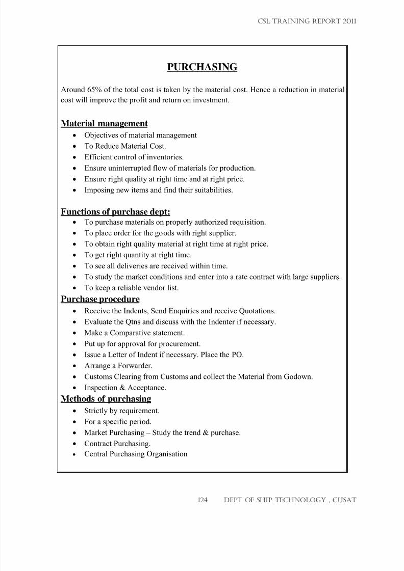
7/23/2019 CSL FINAL_3
http://slidepdf.com/reader/full/csl-final3 124/132
PURCHASING
Around 65% of the total cost is taken by the material cost. Hence a reduction in material
cost will improve the profit and return on investment.
Material management
• Objectives of material management
• To Reduce Material Cost.
• Efficient control of inventories.
• Ensure uninterrupted flow of materials for production.
• Ensure right quality at right time and at right price.
• Imposing new items and find their suitabilities.
Functions of purchase dept: • To purchase materials on properly authorized requisition.
• To place order for the goods with right supplier.
• To obtain right quality material at right time at right price.
• To get right quantity at right time.
• To see all deliveries are received within time.
• To study the market conditions and enter into a rate contract with large suppliers.
• To keep a reliable vendor list.
Purchase procedure• Receive the Indents, Send Enquiries and receive Quotations.
• Evaluate the Qtns and discuss with the Indenter if necessary.
• Make a Comparative statement.
• Put up for approval for procurement.
• Issue a Letter of Indent if necessary. Place the PO.
• Arrange a Forwarder.
• Customs Clearing from Customs and collect the Material from Godown.
• Inspection & Acceptance.
Methods of purchasing• Strictly by requirement.
• For a specific period.
• Market Purchasing – Study the trend & purchase.
• Contract Purchasing.
• Central Purchasing Organisation
CSL TRAINING REPORT 2011
124 DEPT OF SHIP TECHNOLOGY , CUSAT
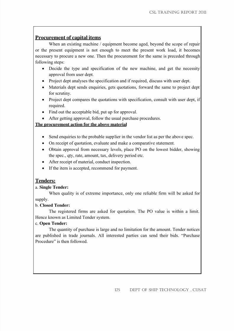
7/23/2019 CSL FINAL_3
http://slidepdf.com/reader/full/csl-final3 125/132
Procurement of capital items
When an existing machine / equipment become aged, beyond the scope of repair
or the present equipment is not enough to meet the present work load, it becomes
necessary to procure a new one. Then the procurement for the same is preceded throughfollowing steps:
• Decide the type and specification of the new machine, and get the necessity
approval from user dept.
• Project dept analyses the specification and if required, discuss with user dept.
• Materials dept sends enquiries, gets quotations, forward the same to project dept
for scrutiny.
• Project dept compares the quotations with specification, consult with user dept, if
required.
• Find out the acceptable bid, put up for approval.
•
After getting approval, follow the usual purchase procedures.
The procurement action for the above material
• Send enquiries to the probable supplier in the vendor list as per the above spec.
• On receipt of quotation, evaluate and make a comparative statement.
• Obtain approval from necessary levels, place PO on the lowest bidder, showing
the spec., qty, rate, amount, tax, delivery period etc.
• After receipt of material, conduct inspection.
• If the item is accepted, recommend for payment.
Tenders:
a. Single Tender:
When quality is of extreme importance, only one reliable firm will be asked for
supply.
b. Closed Tender:
The registered firms are asked for quotation. The PO value is within a limit.
Hence known as Limited Tender system.
c. Open Tender:
The quantity of purchase is large and no limitation for the amount. Tender notices
are published in trade journals. All interested parties can send their bids. “Purchase
Procedure” is then followed.
CSL TRAINING REPORT 2011
125 DEPT OF SHIP TECHNOLOGY , CUSAT
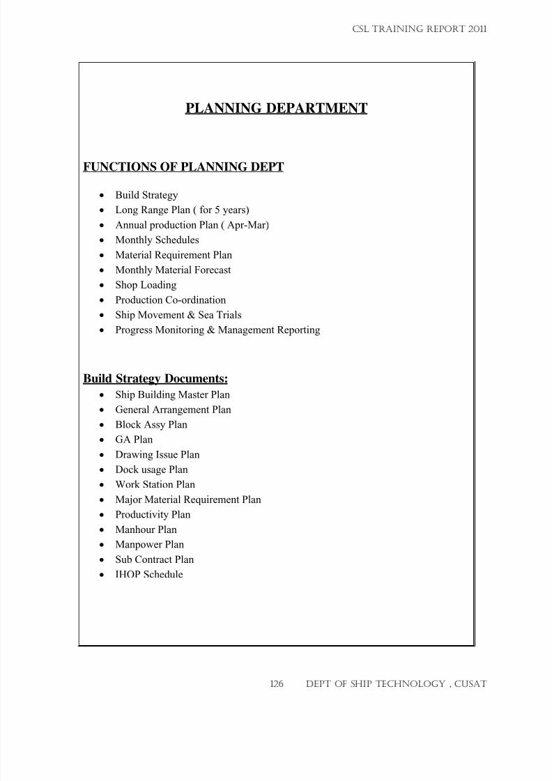
7/23/2019 CSL FINAL_3
http://slidepdf.com/reader/full/csl-final3 126/132
PLANNING DEPARTMENT
FUNCTIONS OF PLANNING DEPT
• Build Strategy
• Long Range Plan ( for 5 years)
• Annual production Plan ( Apr-Mar)
• Monthly Schedules
• Material Requirement Plan
• Monthly Material Forecast
• Shop Loading
• Production Co-ordination
• Ship Movement & Sea Trials
• Progress Monitoring & Management Reporting
Build Strategy Documents:
• Ship Building Master Plan
•
General Arrangement Plan• Block Assy Plan
• GA Plan
• Drawing Issue Plan
• Dock usage Plan
• Work Station Plan
• Major Material Requirement Plan
• Productivity Plan
• Manhour Plan
•
Manpower Plan• Sub Contract Plan
• IHOP Schedule
CSL TRAINING REPORT 2011
126 DEPT OF SHIP TECHNOLOGY , CUSAT
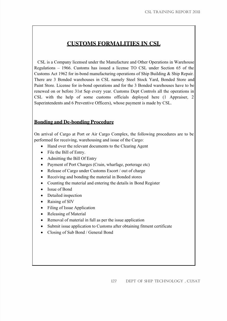
7/23/2019 CSL FINAL_3
http://slidepdf.com/reader/full/csl-final3 127/132
CUSTOMS FORMALITIES IN CSL
CSL is a Company licensed under the Manufacture and Other Operations in Warehouse
Regulations – 1966. Customs has issued a license TO CSL under Section 65 of the
Customs Act 1962 for in-bond manufacturing operations of Ship Building & Ship Repair.
There are 3 Bonded warehouses in CSL namely Steel Stock Yard, Bonded Store and
Paint Store. License for in-bond operations and for the 3 Bonded warehouses have to be
renewed on or before 31st Sep every year. Customs Dept Controls all the operations in
CSL with the help of some customs officials deployed here (1 Appraiser, 2
Superintendents and 6 Preventive Officers), whose payment is made by CSL.
Bonding and De-bonding Procedure
On arrival of Cargo at Port or Air Cargo Complex, the following procedures are to be
performed for receiving, warehousing and issue of the Cargo:
• Hand over the relevant documents to the Clearing Agent
• File the Bill of Entry.
• Admitting the Bill Of Entry
• Payment of Port Charges (Crain, wharfage, porterage etc)
•
Release of Cargo under Customs Escort / out of charge
• Receiving and bonding the material in Bonded stores
• Counting the material and entering the details in Bond Register
• Issue of Bond
• Detailed inspection
• Raising of SIV
• Filing of Issue Application
• Releasing of Material
• Removal of material in full as per the issue application
•
Submit issue application to Customs after obtaining fitment certificate
• Closing of Sub Bond / General Bond
CSL TRAINING REPORT 2011
127 DEPT OF SHIP TECHNOLOGY , CUSAT
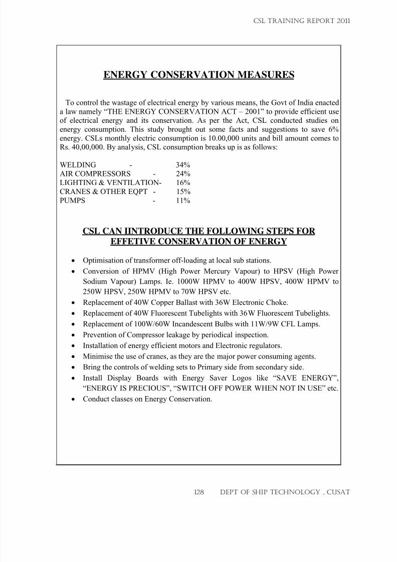
7/23/2019 CSL FINAL_3
http://slidepdf.com/reader/full/csl-final3 128/132
ENERGY CONSERVATION MEASURES
To control the wastage of electrical energy by various means, the Govt of India enacted
a law namely “THE ENERGY CONSERVATION ACT – 2001” to provide efficient useof electrical energy and its conservation. As per the Act, CSL conducted studies on
energy consumption. This study brought out some facts and suggestions to save 6%
energy. CSLs monthly electric consumption is 10.00,000 units and bill amount comes toRs. 40,00,000. By analysis, CSL consumption breaks up is as follows:
WELDING - 34%AIR COMPRESSORS - 24%
LIGHTING & VENTILATION- 16%
CRANES & OTHER EQPT - 15%
PUMPS - 11%
CSL CAN IINTRODUCE THE FOLLOWING STEPS FOR
EFFETIVE CONSERVATION OF ENERGY
• Optimisation of transformer off-loading at local sub stations.
• Conversion of HPMV (High Power Mercury Vapour) to HPSV (High Power
Sodium Vapour) Lamps. Ie. 1000W HPMV to 400W HPSV, 400W HPMV to
250W HPSV, 250W HPMV to 70W HPSV etc.• Replacement of 40W Copper Ballast with 36W Electronic Choke.
• Replacement of 40W Fluorescent Tubelights with 36W Fluorescent Tubelights.
• Replacement of 100W/60W Incandescent Bulbs with 11W/9W CFL Lamps.
• Prevention of Compressor leakage by periodical inspection.
• Installation of energy efficient motors and Electronic regulators.
• Minimise the use of cranes, as they are the major power consuming agents.
• Bring the controls of welding sets to Primary side from secondary side.
• Install Display Boards with Energy Saver Logos like “SAVE ENERGY”,
“ENERGY IS PRECIOUS”, “SWITCH OFF POWER WHEN NOT IN USE” etc.
•
Conduct classes on Energy Conservation.
CSL TRAINING REPORT 2011
128 DEPT OF SHIP TECHNOLOGY , CUSAT
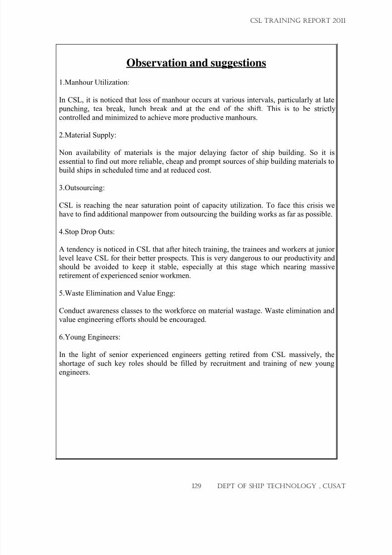
7/23/2019 CSL FINAL_3
http://slidepdf.com/reader/full/csl-final3 129/132
Observation and suggestions
1.Manhour Utilization:
In CSL, it is noticed that loss of manhour occurs at various intervals, particularly at late punching, tea break, lunch break and at the end of the shift. This is to be strictly
controlled and minimized to achieve more productive manhours.
2.Material Supply:
Non availability of materials is the major delaying factor of ship building. So it is
essential to find out more reliable, cheap and prompt sources of ship building materials to
build ships in scheduled time and at reduced cost.
3.Outsourcing:
CSL is reaching the near saturation point of capacity utilization. To face this crisis we
have to find additional manpower from outsourcing the building works as far as possible.
4.Stop Drop Outs:
A tendency is noticed in CSL that after hitech training, the trainees and workers at junior
level leave CSL for their better prospects. This is very dangerous to our productivity andshould be avoided to keep it stable, especially at this stage which nearing massiveretirement of experienced senior workmen.
5.Waste Elimination and Value Engg:
Conduct awareness classes to the workforce on material wastage. Waste elimination and
value engineering efforts should be encouraged.
6.Young Engineers:
In the light of senior experienced engineers getting retired from CSL massively, the
shortage of such key roles should be filled by recruitment and training of new young
engineers.
CSL TRAINING REPORT 2011
129 DEPT OF SHIP TECHNOLOGY , CUSAT
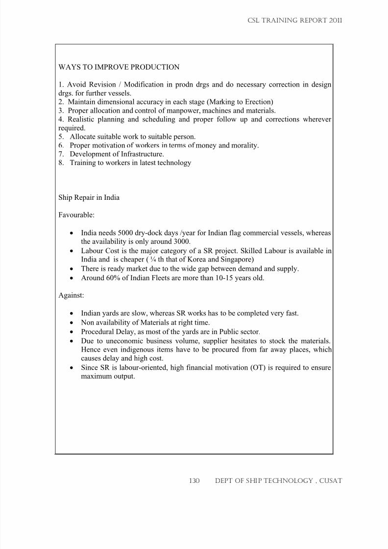
7/23/2019 CSL FINAL_3
http://slidepdf.com/reader/full/csl-final3 130/132
WAYS TO IMPROVE PRODUCTION
1. Avoid Revision / Modification in prodn drgs and do necessary correction in design
drgs. for further vessels.2. Maintain dimensional accuracy in each stage (Marking to Erection)
3. Proper allocation and control of manpower, machines and materials.
4. Realistic planning and scheduling and proper follow up and corrections wherever
required.5. Allocate suitable work to suitable person.
6. Proper motivation of workers in terms of money and morality.
7. Development of Infrastructure.8. Training to workers in latest technology
Ship Repair in India
Favourable:
• India needs 5000 dry-dock days /year for Indian flag commercial vessels, whereasthe availability is only around 3000.
• Labour Cost is the major category of a SR project. Skilled Labour is available in
India and is cheaper ( ¼ th that of Korea and Singapore)
• There is ready market due to the wide gap between demand and supply.
• Around 60% of Indian Fleets are more than 10-15 years old.
Against:
• Indian yards are slow, whereas SR works has to be completed very fast.
• Non availability of Materials at right time.
• Procedural Delay, as most of the yards are in Public sector.
• Due to uneconomic business volume, supplier hesitates to stock the materials.
Hence even indigenous items have to be procured from far away places, which
causes delay and high cost.
• Since SR is labour-oriented, high financial motivation (OT) is required to ensuremaximum output.
CSL TRAINING REPORT 2011
130 DEPT OF SHIP TECHNOLOGY , CUSAT
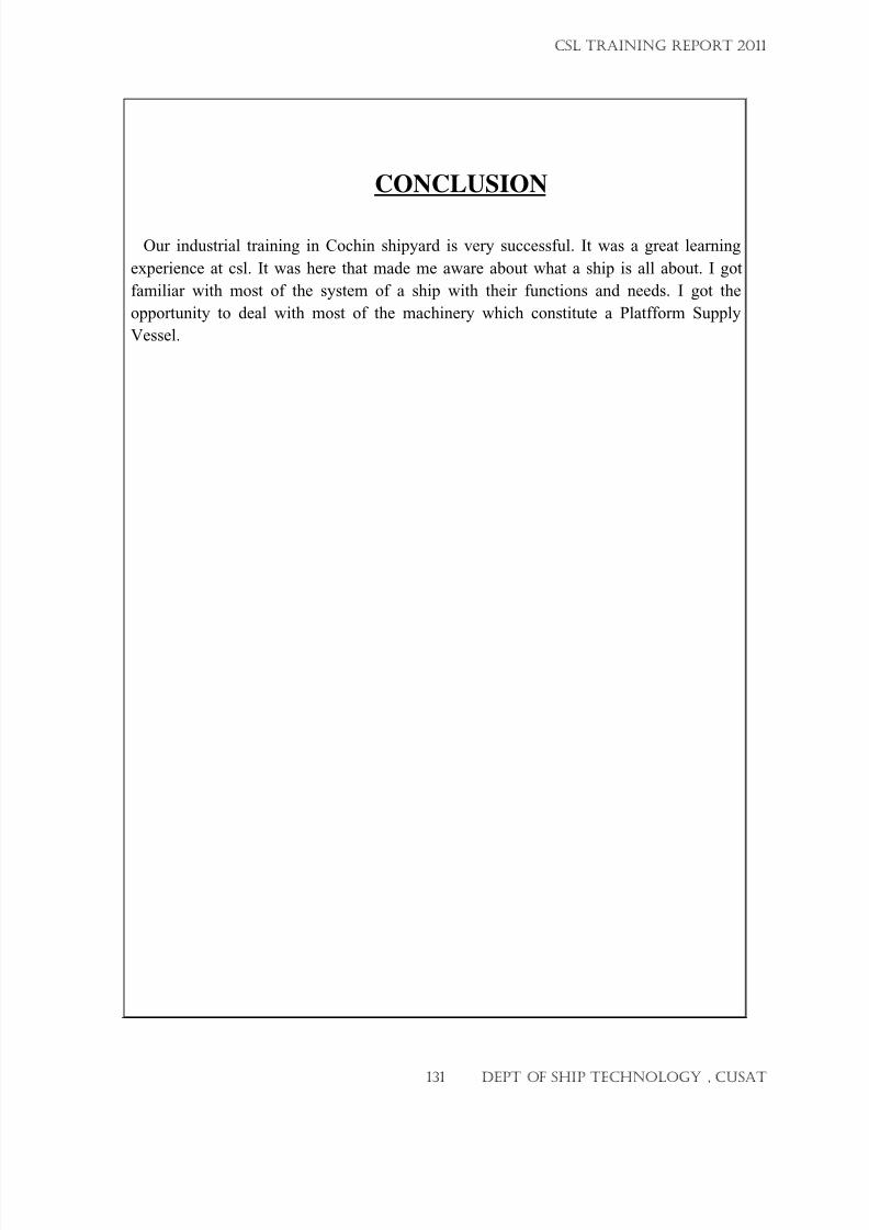
7/23/2019 CSL FINAL_3
http://slidepdf.com/reader/full/csl-final3 131/132
CONCLUSION
Our industrial training in Cochin shipyard is very successful. It was a great learning
experience at csl. It was here that made me aware about what a ship is all about. I got
familiar with most of the system of a ship with their functions and needs. I got the
opportunity to deal with most of the machinery which constitute a Platfform Supply
Vessel.
CSL TRAINING REPORT 2011
131 DEPT OF SHIP TECHNOLOGY , CUSAT
7/23/2019 CSL FINAL_3
http://slidepdf.com/reader/full/csl-final3 132/132
REFERENCE
1.
www.cochinshipyard.com 2. CSL HANDBOOK
CSL TRAINING REPORT 2011