CSE A215 Assembly Language Programming for Engineersssiewert/a225_doc/... · CSE A215 Assembly...
23
September 20, 2012 Sam Siewert CSE A215 Assembly Language Programming for Engineers Lecture 4 & 5 – Logic Design Review (Chapter 3 And Appendices C&D in COD CDROM)
-
Upload
vuongkhanh -
Category
Documents
-
view
223 -
download
4
Transcript of CSE A215 Assembly Language Programming for Engineersssiewert/a225_doc/... · CSE A215 Assembly...
September 20, 2012 Sam Siewert
CSE A215 Assembly Language Programming
for Engineers Lecture 4 & 5 – Logic Design Review
(Chapter 3 And Appendices C&D in COD CDROM)

ALU Quick Review
Conceptual ALU Operation
Sam Siewert
2
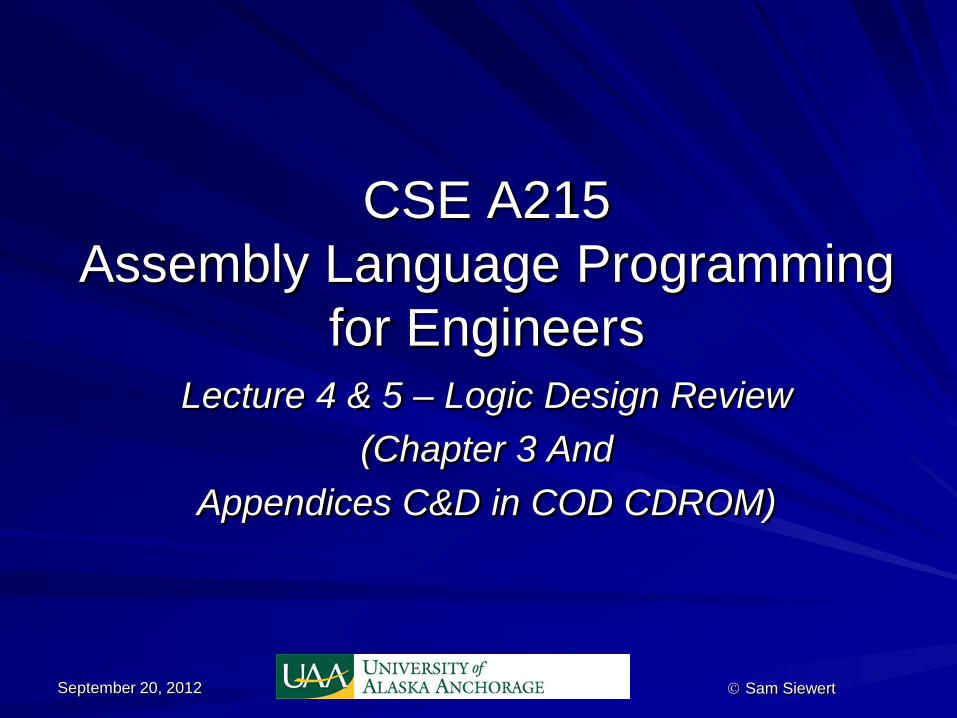
Quick Primer on State Machines States are Circles Transitions Occur Due to an Input and Produce an Output Transitions Cause One State to be left and a new State to be Entered Input is External to the State Machine Ouput is produced external to the State Machine E.g. Switch with LED to Indicate Power State
Sam Siewert 3
Off On Power-on / LED-on
Power-off / LED-off
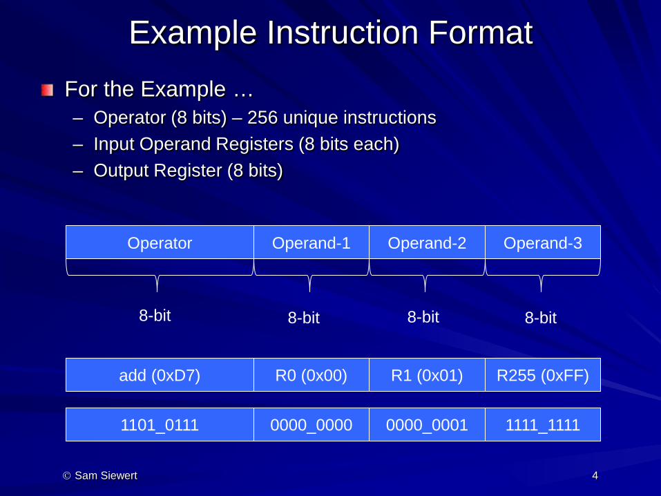
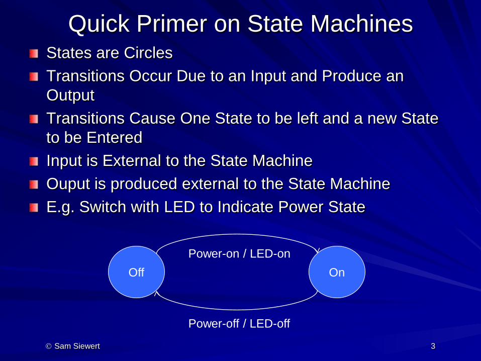
Example Instruction Format For the Example … – Operator (8 bits) – 256 unique instructions – Input Operand Registers (8 bits each) – Output Register (8 bits)
Sam Siewert 4
Operator Operand-1 Operand-2 Operand-3
8-bit 8-bit 8-bit 8-bit
add (0xD7) R0 (0x00) R1 (0x01) R255 (0xFF)
1101_0111 0000_0000 0000_0001 1111_1111
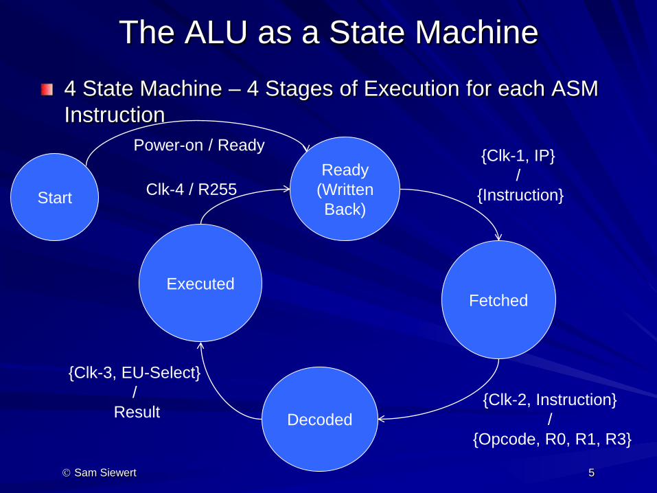
The ALU as a State Machine 4 State Machine – 4 Stages of Execution for each ASM Instruction
Sam Siewert 5
Start
Ready (Written Back)
Power-on / Ready
Fetched
{Clk-1, IP} /
{Instruction}
Decoded {Clk-2, Instruction}
/ {Opcode, R0, R1, R3}
Executed
{Clk-3, EU-Select} /
Result
Clk-4 / R255
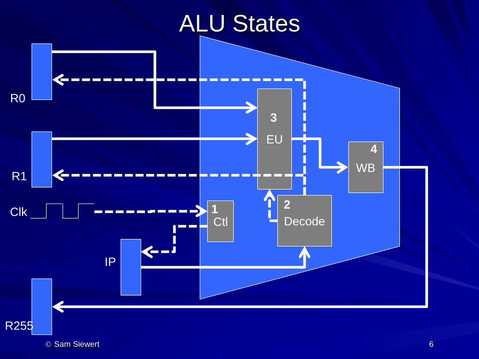
ALU States
Sam Siewert 6
R255
R0
R1
EU
Ctl
IP
Decode 1 2
3
Clk
WB 4
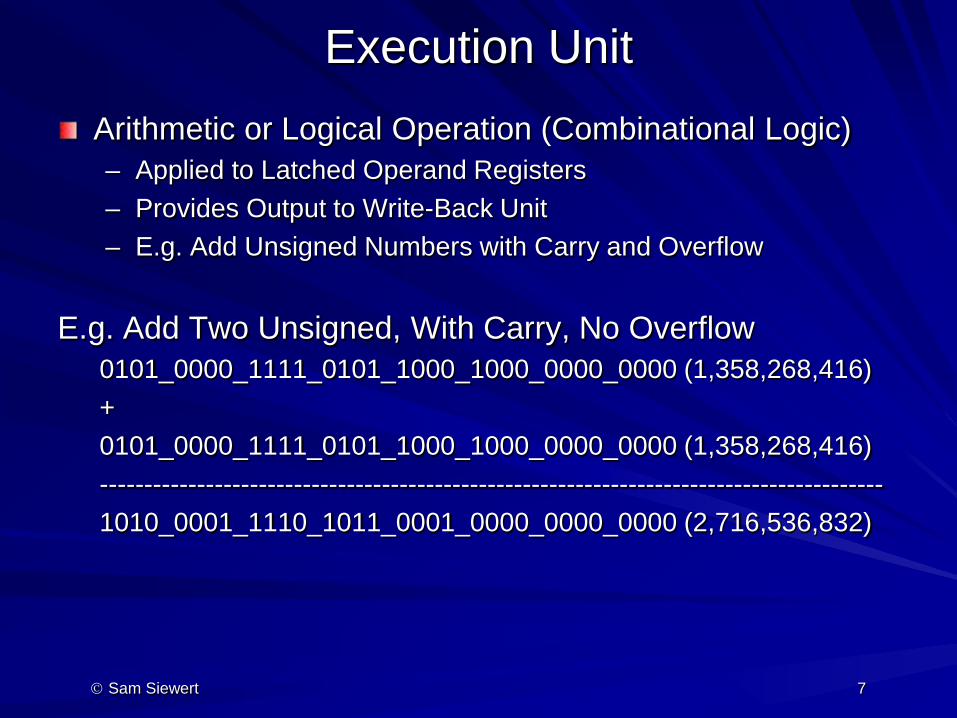
Execution Unit Arithmetic or Logical Operation (Combinational Logic) – Applied to Latched Operand Registers – Provides Output to Write-Back Unit – E.g. Add Unsigned Numbers with Carry and Overflow
E.g. Add Two Unsigned, With Carry, No Overflow 0101_0000_1111_0101_1000_1000_0000_0000 (1,358,268,416) + 0101_0000_1111_0101_1000_1000_0000_0000 (1,358,268,416) ----------------------------------------------------------------------------------------- 1010_0001_1110_1011_0001_0000_0000_0000 (2,716,536,832)
Sam Siewert 7
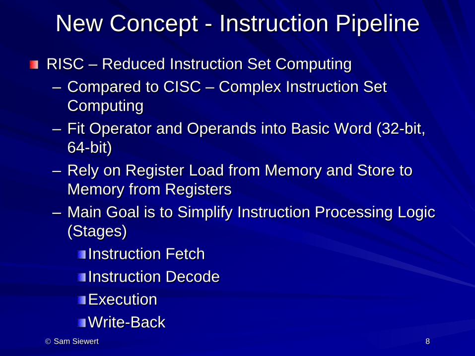
New Concept - Instruction Pipeline RISC – Reduced Instruction Set Computing – Compared to CISC – Complex Instruction Set
Computing – Fit Operator and Operands into Basic Word (32-bit,
64-bit) – Rely on Register Load from Memory and Store to
Memory from Registers – Main Goal is to Simplify Instruction Processing Logic
(Stages) Instruction Fetch Instruction Decode Execution Write-Back
Sam Siewert 8
Sam Siewert 9
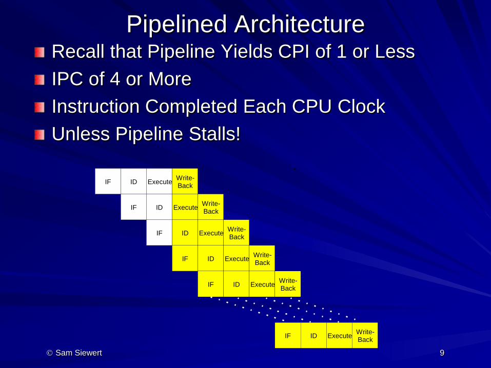
Pipelined Architecture Recall that Pipeline Yields CPI of 1 or Less IPC of 4 or More Instruction Completed Each CPU Clock Unless Pipeline Stalls!
IF ID Execute Write- Back
IF ID Execute Write- Back
IF ID Execute Write- Back
IF ID Execute Write- Back
IF ID Execute Write- Back
IF ID Execute Write- Back
Pipeline with Micro-parallelism Goal is to Retire (and Write-Back Result) at Least ONE instruction per Clock – CPI of 1.0 or Less – IPC of 1.0 or Greater
Requires Ability to Overlap IF, ID, Execution and Write-Back Pipeline Stages Fully Pipeline Hazards Can Stall this Overlap of Stages – Cache Miss – Load or Store Takes Far Longer than 1 Cycle – Data Dependencies – Need Data From Slow Memory to Proceed – Register Pressure – All Registers are Tied Up with Out-standing
(incomplete Instructions) – Branch Mis-prediction – Requires Alternate Branch Recovery
(Speculative Branch Execution)
Sam Siewert 10
Pipeline Depth and RISC vs. CISC RISC Simplification to Processing Logic Limits Pipeline Depth to 4 stages typically CISC Has Complex Instructions with Advanced Memory Access, More Operands (than can fit in a word) and many other convenient features, but requires many more stages for pipelining – CISC Can be Pipelined (and has been done – e.g. x86 ISA) – CISC Can be composed of micro-code that is easier to pipeline – Takes fewer instructions to implement the same C statement –
simpler code generation
RISC is simple, but most often requires more ASM operations to code the same C code statement (algorithm)
Sam Siewert 11
Logic Design
Combinational and Sequential Logic Primer (Appendix C)
Sam Siewert
12
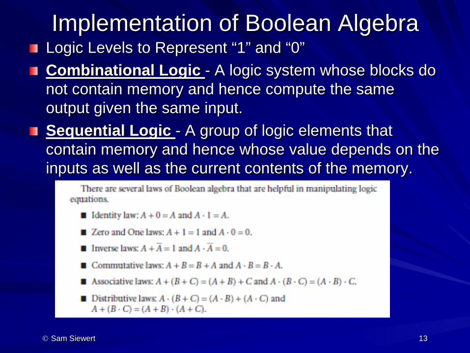
Implementation of Boolean Algebra Logic Levels to Represent “1” and “0” Combinational Logic - A logic system whose blocks do not contain memory and hence compute the same output given the same input. Sequential Logic - A group of logic elements that contain memory and hence whose value depends on the inputs as well as the current contents of the memory.
Sam Siewert 13
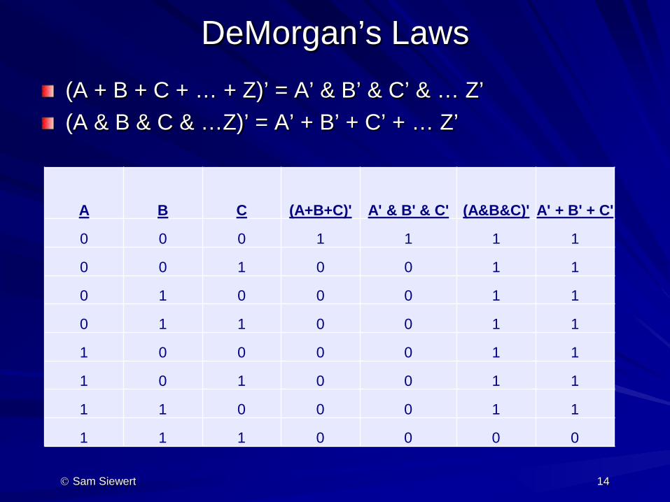
DeMorgan’s Laws (A + B + C + … + Z)’ = A’ & B’ & C’ & … Z’ (A & B & C & …Z)’ = A’ + B’ + C’ + … Z’
Sam Siewert 14
A B C (A+B+C)' A' & B' & C' (A&B&C)' A' + B' + C'
0 0 0 1 1 1 1
0 0 1 0 0 1 1
0 1 0 0 0 1 1
0 1 1 0 0 1 1
1 0 0 0 0 1 1
1 0 1 0 0 1 1
1 1 0 0 0 1 1
1 1 1 0 0 0 0
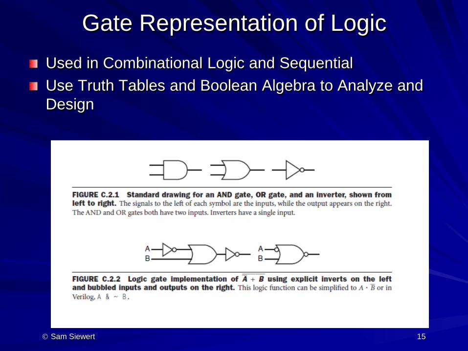
Gate Representation of Logic Used in Combinational Logic and Sequential Use Truth Tables and Boolean Algebra to Analyze and Design
Sam Siewert 15
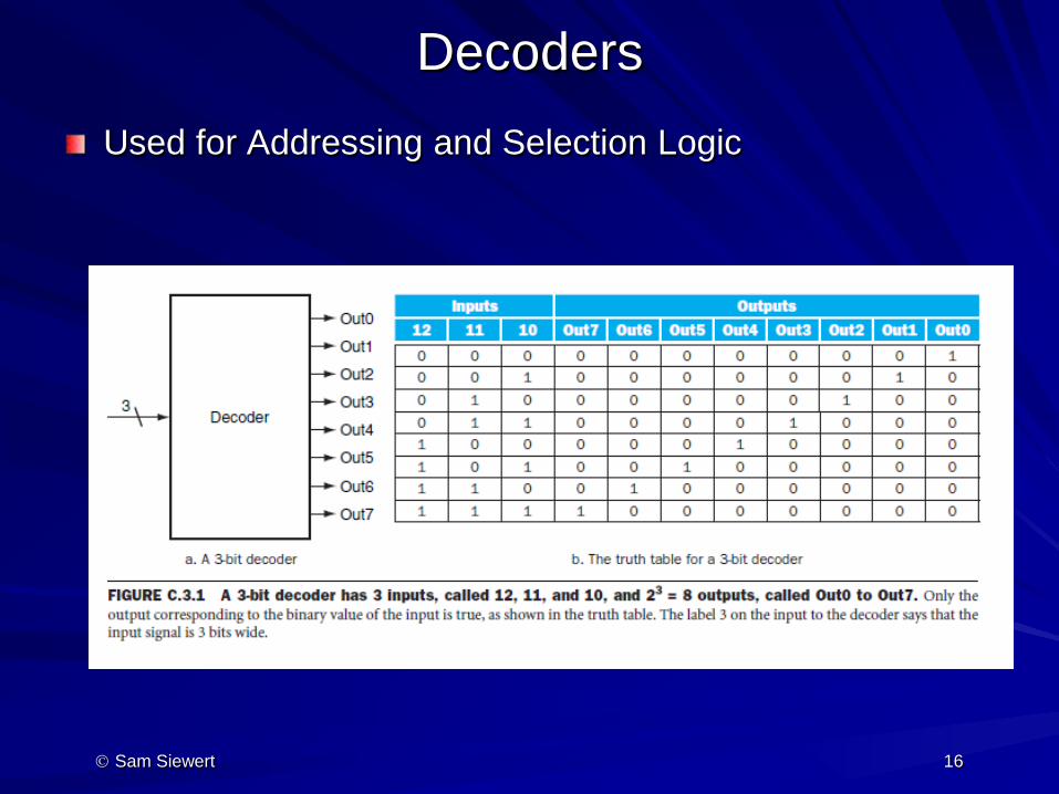
Decoders Used for Addressing and Selection Logic
Sam Siewert 16
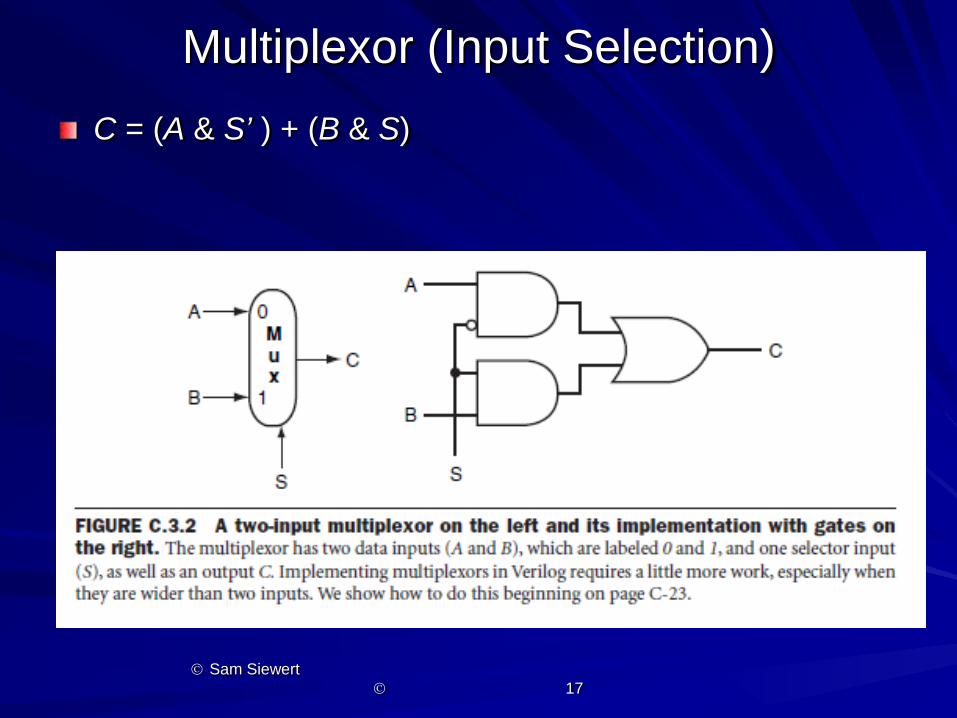
Multiplexor (Input Selection) C = (A & S’ ) + (B & S)
Sam Siewert 17

Building XOR from And/Or/Not Example of Assertion that all Logic can be Derived from 3 Basic Logic Operators
Sam Siewert 18
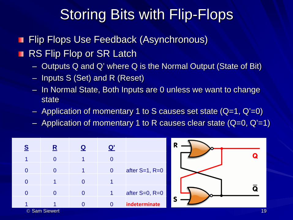
Storing Bits with Flip-Flops Flip Flops Use Feedback (Asynchronous) RS Flip Flop or SR Latch – Outputs Q and Q’ where Q is the Normal Output (State of Bit) – Inputs S (Set) and R (Reset) – In Normal State, Both Inputs are 0 unless we want to change
state – Application of momentary 1 to S causes set state (Q=1, Q’=0) – Application of momentary 1 to R causes clear state (Q=0, Q’=1)
Sam Siewert 19
S R Q Q'
1 0 1 0
0 0 1 0 after S=1, R=0
0 1 0 1
0 0 0 1 after S=0, R=0
1 1 0 0 indeterminate
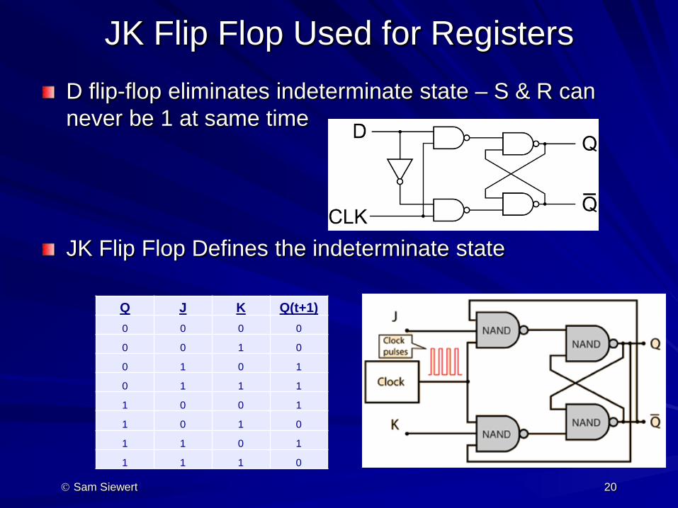
JK Flip Flop Used for Registers D flip-flop eliminates indeterminate state – S & R can never be 1 at same time
JK Flip Flop Defines the indeterminate state
Sam Siewert 20
Q J K Q(t+1) 0 0 0 0
0 0 1 0
0 1 0 1
0 1 1 1
1 0 0 1
1 0 1 0
1 1 0 1
1 1 1 0

PLA for 2-layer Logic Using COD Example Truth Table
Sam Siewert 21
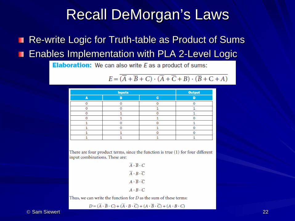
Recall DeMorgan’s Laws Re-write Logic for Truth-table as Product of Sums Enables Implementation with PLA 2-Level Logic
Sam Siewert 22
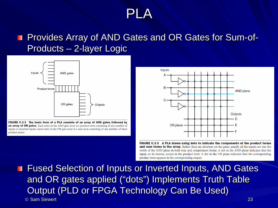
PLA Provides Array of AND Gates and OR Gates for Sum-of-Products – 2-layer Logic Fused Selection of Inputs or Inverted Inputs, AND Gates and OR gates applied (“dots”) Implements Truth Table Output (PLD or FPGA Technology Can Be Used) Sam Siewert 23