
CSC 8260-Chapter 17: Real-Time Ethernet for …hzhang/courses/8260/Lectures/Chapter 17...CSC...
56
CSC 8260-Chapter 17: Real-Time Ethernet for Automation Applications Yuehua Wang
Transcript of CSC 8260-Chapter 17: Real-Time Ethernet for …hzhang/courses/8260/Lectures/Chapter 17...CSC...

CSC 8260-Chapter 17: Real-Time Ethernet for Automation Applications
Yuehua Wang

Outline
Introduction
Structure of the IEC Standardization
Real-Time Requirements
Practical Realizations
Conclusion

Introduction Internet of things
Enabled by Ethernet and TCP/IP protocol
Low cost
Widely deployed
Everything, anywhere
Make life much easier
Automation world
Dedicated field buses (the name of a family of industrial computer network protocols used for real-time distributed control, standardized as IEC 61158)
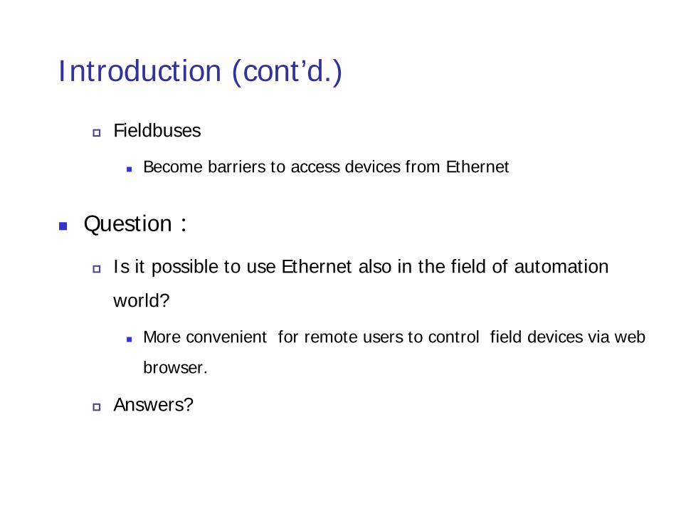
Introduction (cont’d.)
Fieldbuses
Become barriers to access devices from Ethernet
Question:
Is it possible to use Ethernet also in the field of automation world?
More convenient for remote users to control field devices via web browser.
Answers?

What are scenarios in Automation?
Time deterministic communication
Time-synchronized actions between field devices
Efficient and frequent exchange of very small data records
However, Ethernet and its applications
Best-effort model
No QoS guarantees
Jitters, packet loss, and long packet delay

Migration of the Ethernet to Real-Time Ethernet (RTE)
Become a necessity in the field of automation world
Existing studies
Introduce quality of service
Modify packet processing in switch
Synchronize field devices.
The IEC/SC65C committee
in addition to the maintenance of the international fieldbus and its profiles
Finished a standardization project and defined aspects of RTE

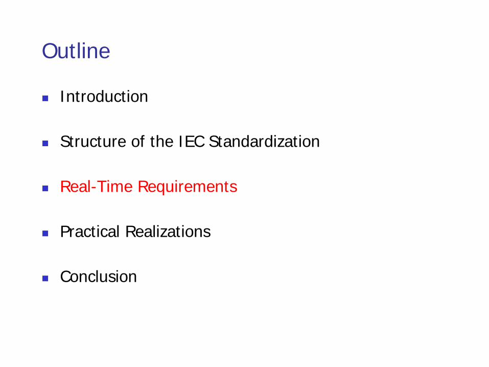
Outline
Introduction
Structure of the IEC Standardization
Real-Time Requirements
Practical Realizations
Conclusion

Structure of the IEC Standardization
IEC 61158
Standard including all industrial protocols
structured according to the Open System Interface (OSI) reference model in seven parts
all networks identified by types
24 different types in 6 different parts

IEC 61784
Standard collecting sets of profiles
some versions based on Ethernet technology are also defined.
ISO/IEC 8802-3(Ethernet)-based

To identify all these profiles,


CPFs denotes communication profile families
CPs represents communication profiles
which is a set of policies that determine how to communicate with other devices.
Full table can be found on Pages 17-4 and 17-5
Table 17.2 covers
functional safe communications, secure communications, installation profiles for communication networks
not discussed in this talk (Ch17)
Outline
Introduction
Structure of the IEC Standardization
Real-Time Requirements
Practical Realizations
Conclusion

Real-Time Requirements
The users of an RTE network
different requirements
different applications
Performance indicators
Requirements defined in IEC 61784-2 (Table 17.2)
Defines the requirements for a class of applications
Have limits or ranges
Are interdependent

PIs are defined in the CPs for RTE (IEC 61784-2):
Delivery time
Number of RTE end-stations
Basic network topology
Number of switches between RTE end-stations
RTE throughput
Non-RTE bandwidth
Time synchronization accuracy
Non-time-based synchronization accuracy
Redundancy recovery time

Delivery time
is the time needed to convey a service data unit (SDU, message payload) from one node (source) to another node (destination). The delivery time is measured at the application layer interface.
The maximum delivery time shall be stated for the two cases of no transmission errors and one lost frame with recovery.
Using delivery time as a performance indicator, there are three classifications

Three classifications
Low speed class for human control
delivery times around 100 ms
Typical for the case of humans involved in the system observation
Most processes in process automation and building control fall into this class
Use Basic Ethernet and TCP/IP protocol
Class for process control
Delivery times below 10 ms
for most tooling machine control system like PLCs or PC-based control, special effort has to be taken in the RTE equipment
Powerful and expensive computer resources are needed to handle the TCP/IP protocol in RT
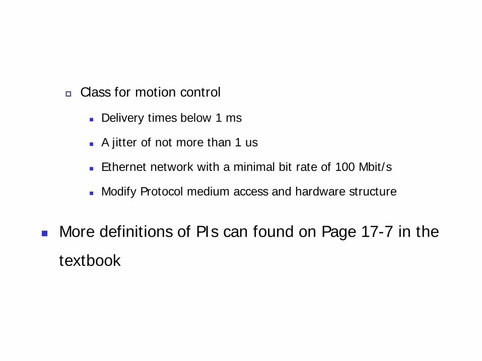
Class for motion control
Delivery times below 1 ms
A jitter of not more than 1 us
Ethernet network with a minimal bit rate of 100 Mbit/s
Modify Protocol medium access and hardware structure
More definitions of PIs can found on Page 17-7 in the textbook

Outline
Introduction
Structure of the IEC Standardization
Real-Time Requirements
Practical Realizations
Conclusion
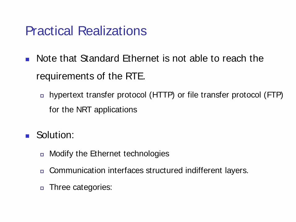
Practical Realizations
Note that Standard Ethernet is not able to reach the requirements of the RTE.
hypertext transfer protocol (HTTP) or file transfer protocol (FTP) for the NRT applications
Solution:
Modify the Ethernet technologies
Communication interfaces structured indifferent layers.
Three categories:
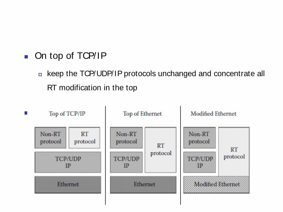
On top of TCP/IP
keep the TCP/UDP/IP protocols unchanged and concentrate all RT modification in the top
layer;
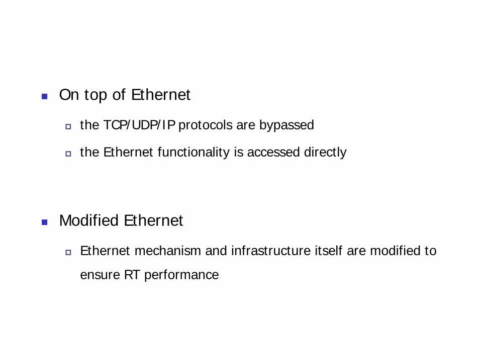
On top of Ethernet
the TCP/UDP/IP protocols are bypassed
the Ethernet functionality is accessed directly
Modified Ethernet
Ethernet mechanism and infrastructure itself are modified to ensure RT performance

“On Top of TC P/IP” Protocols
Realization of …
use the TCP/UDP/IP protocol stack
nondeterministic delays
Need extra resource in processing power and memory
Examples:
Modbus/TCP (Profile 15/1 and 15/2)
EtherNet/IP (Profile 2/2 and 2/2.1)
P-NET (Profile 4/3)
Vnet/IP (Profile 10/1)

Modbus/TCP (Profile 15/1 and 15/2)
probably one of the most widely used Ethernet solutions in industrial applications today
Modbus defined by Schneider Electric in 1979
a request/reply protocol using port 502
send a request frame
get back a reply frame

Modbus/TCP
the actual definition must be extended with service definitions for the integration in international standards
New RT extensions (profile 15/2)
real-time publisher subscriber (RTPS) protocol
two main communication models
publish–subscribe:transfers data from publishers to subscribers
composite state transfer (CST) protocol transfers state informationfrom a writer to a reader.
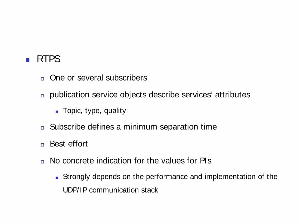
RTPS
One or several subscribers
publication service objects describe services’ attributes
Topic, type, quality
Subscribe defines a minimum separation time
Best effort
No concrete indication for the values for PIs
Strongly depends on the performance and implementation of the UDP/IP communication stack

EtherNet/IP (Profile 2/2 and 2/2.1)
defined by Rockwell and supported by the Open DeviceNet Vendor Association (ODVA)†and ControlNetInternational
standardized in IEC 61784-1 as profile 2/2 (using type 2 specifications in IEC 61158)—already provides ISO/IEC 8802-3-based RT communication.

makes use of the common industrial protocol (CIP)
An industrial protocol for industrial automation applications
Time synchronizing with IEEE 1588 protocol (accuracy of 0.5 μs)
Defines objects to transport control-oriented data and other related information (e.g., parameters and diagnostics)

P-NET (Profile 4/3)
proposed by the Danish national committee
RT communication wrapped into UDP/IP packages
P-NET packages routed through both IP networks and any type of P-NET network
IP specification just defines how to tunnel over UDP/IP network
No special mechanism for real-time delivery guarantee

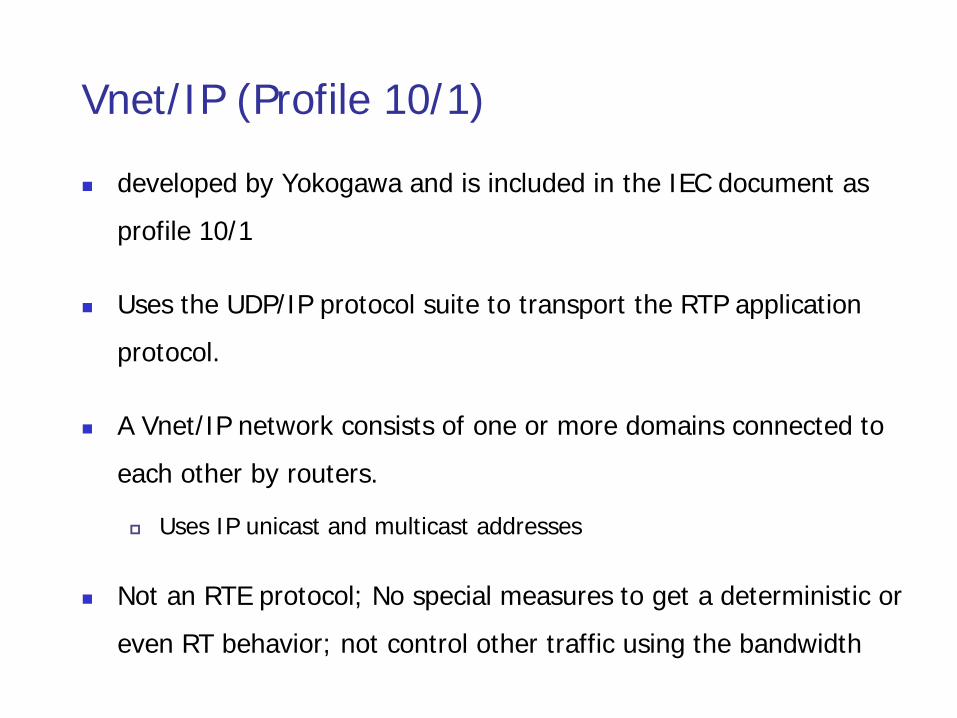
Vnet/IP (Profile 10/1)
developed by Yokogawa and is included in the IEC document as profile 10/1
Uses the UDP/IP protocol suite to transport the RTP application protocol.
A Vnet/IP network consists of one or more domains connected to each other by routers.
Uses IP unicast and multicast addresses
Not an RTE protocol; No special measures to get a deterministic or even RT behavior; not control other traffic using the bandwidth

one or more domains connected to each other by routers
10 ms: the min cycle time of scheduling of RT traffic
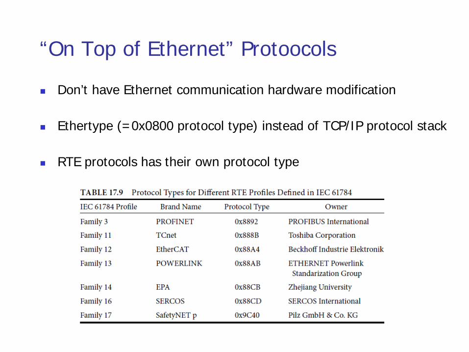
“On Top of Ethernet” Protoocols
Don’t have Ethernet communication hardware modification
Ethertype (=0x0800 protocol type) instead of TCP/IP protocol stack
RTE protocols has their own protocol type
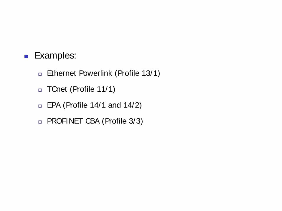
Examples:
Ethernet Powerlink (Profile 13/1)
TCnet (Profile 11/1)
EPA (Profile 14/1 and 14/2)
PROFINET CBA (Profile 3/3)

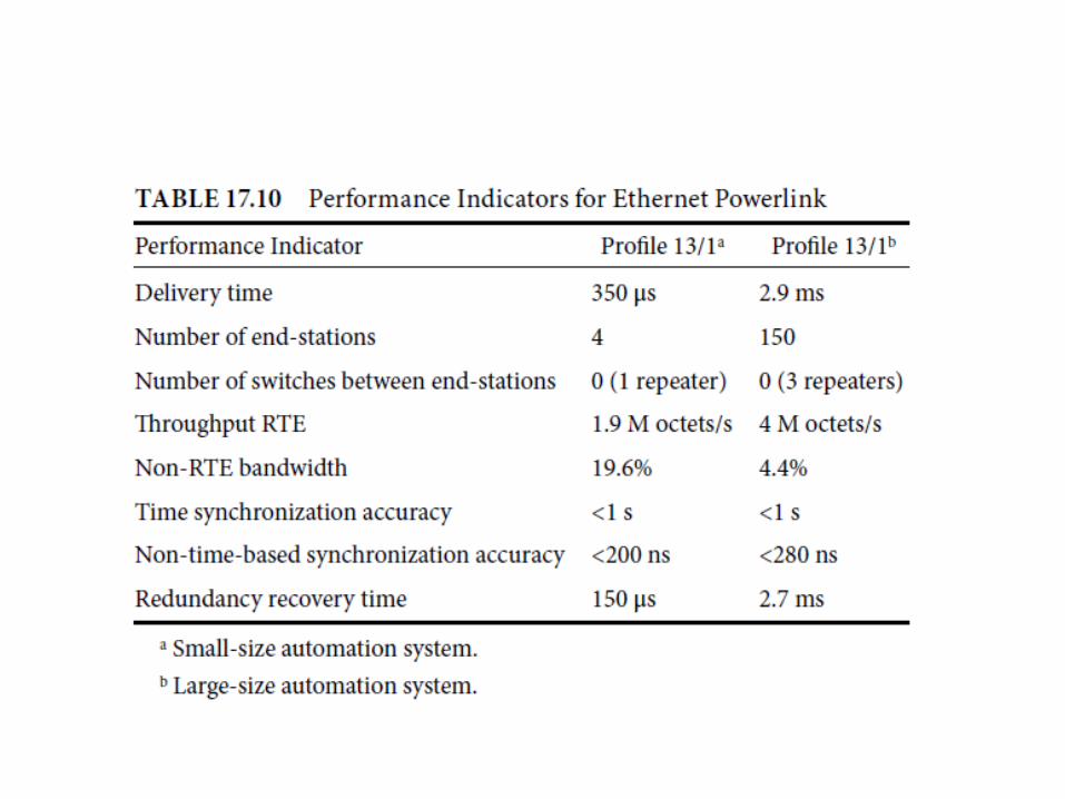
Ethernet Powerlink (Profile 13/1)
EPL was defined by Bernecker + Rainer (B&R)
is now supported by the Ethernet Powerlink Standardisation Group (EPSG).*
A protected Ethernet
No slaves can talk without permission
Master–slave scheduling
SCNM: slot communication network management
MN: managing node, i.e., the master
CNs: controlled nodes sending on request by the MN
SoC: start-of-cycle frame issued by the MN to start the cycle

Preq: Poll-Request frame (unicast) for configuration
PRes: Poll-Response frame (mulicast)
SoA: Start-of-Asynchronous frame
UDP/IP
(+) No interference and guaranteed communication time

Multiple Ethernet segments
MNs exchange messages
Synchronize using distributed clocks
routing functionality specified by the MNs, e.g., IP
Application
CANopen: define process data objects (PDOs) to control the physical process and service data objects (SDOs)
PDOs use isochronous EPL communication
SDOs use UDP/IP protocol

TCnet (Time-Critical Control Network) (Profile 11/1)
is a proposal from Toshiba
Uses modified standard MAC* access CSMA/CD†
A cycle is called a high-speed-transmission period
Node 1broadcast Node 2

high-, medium-, and low-speed cyclic data transmission
First send high-speed cyclic data
TCnet handles redundant transmission media, for low recovery time
two inputs of received frames
two outputs to two redundant transmission media
Application: common memory system (virtual memory)

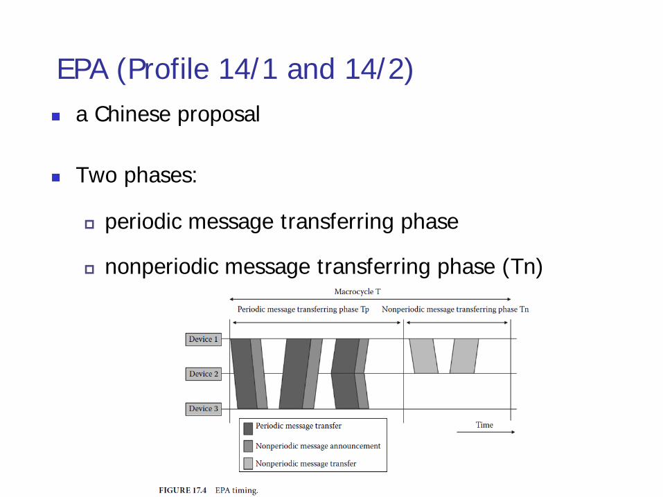
EPA (Profile 14/1 and 14/2) a Chinese proposal
Two phases:
periodic message transferring phase
nonperiodic message transferring phase (Tn)

two kinds of application processes
EPA function block application processes
NRT application processes (TCP/IP)
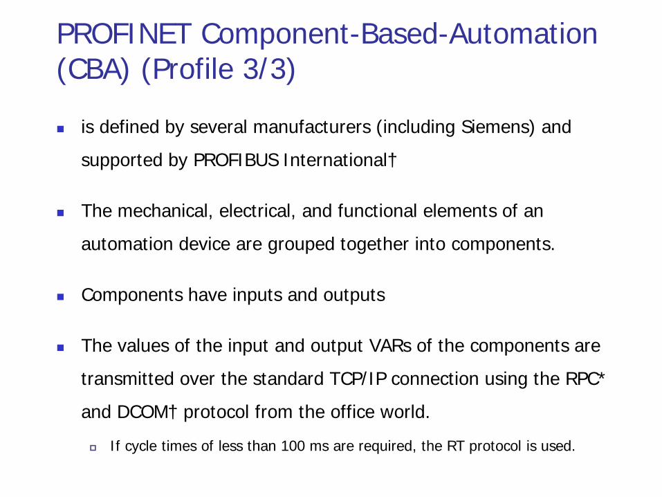
PROFINET Component-Based-Automation (CBA) (Profile 3/3)
is defined by several manufacturers (including Siemens) and supported by PROFIBUS International†
The mechanical, electrical, and functional elements of an automation device are grouped together into components.
Components have inputs and outputs
The values of the input and output VARs of the components are transmitted over the standard TCP/IP connection using the RPC* and DCOM† protocol from the office world. If cycle times of less than 100 ms are required, the RT protocol is used.
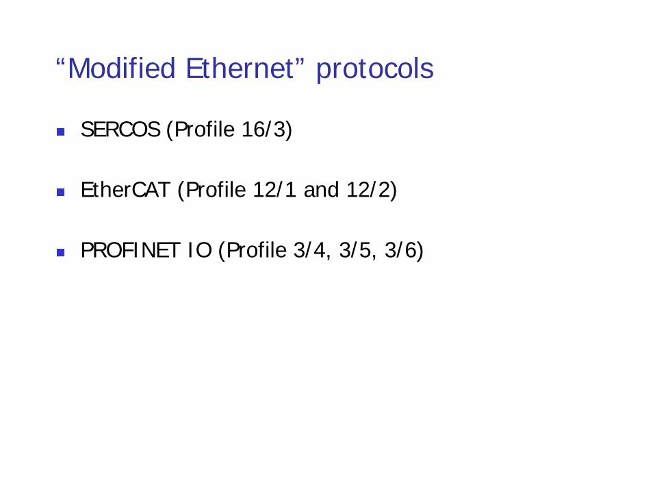
“Modified Ethernet” protocols
SERCOS (Profile 16/3)
EtherCAT (Profile 12/1 and 12/2)
PROFINET IO (Profile 3/4, 3/5, 3/6)

SERCOS (Profile 16/3)
a daisy chain (line structure) or a ring (ring structure)
Only the free port of the last slave in a line structure may be connected to a switch if required by the configuration, for example, for communication with devices via TCP/IP or UDP/UDP.
consists of two different logical communication channels:
RT channel
IP channel

The communication cycle consists of
up to four master data telegrams (MDTs)
up to four device telegrams (ATs¶) in the RT channel and the IP channel

MDTs are transmitted by the master and received by each slave
Synchronization information and a data record for each slave
The ATs are transmitted by the master as an empty frame with predefined fields but without information. Each slave inserts its data into data fields allocated to it in the ATs.

EtherCAT (Profile 12/1 and 12/2)

A line topology
In order to achieve maximum performance,
the Ethernet frames should be processed “on the fly.”
To realize such a node, a special ASIC* is needed for medium access, which integrates a two-port switch into the actual device.


PROFINET IO (Profile 3/4, 3/5, 3/6)
defined by several manufacturers (including Siemens) and supported by PROFIBUS International†

isochronous RT (IRT)
all IRT frames are transmitted based on a a predefined and configured timetable
RT
address-based communication and devices behave as standard Ethernet switches
devices are synchronized by means of a modified IEEE 1588 mechanism with “onthe fly” stamping
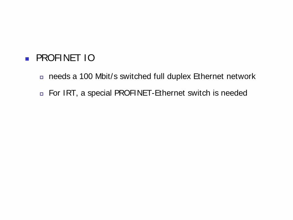
PROFINET IO
needs a 100 Mbit/s switched full duplex Ethernet network
For IRT, a special PROFINET-Ethernet switch is needed

Outline
Introduction
Structure of the IEC Standardization
Real-Time Requirements
Practical Realizations
Conclusion
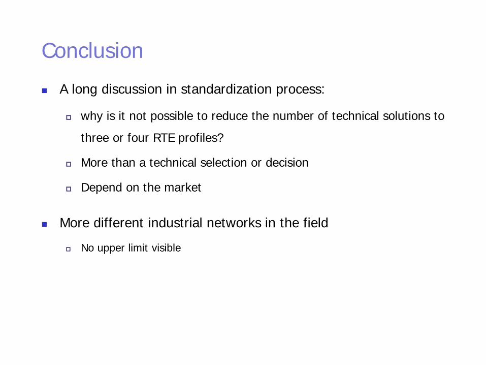
Conclusion A long discussion in standardization process:
why is it not possible to reduce the number of technical solutions to three or four RTE profiles?
More than a technical selection or decision
Depend on the market
More different industrial networks in the field No upper limit visible


