
CSC 778 Presentation Waveband Switching Neil D’souza Jonathan Grice.
47
CSC 778 Presentation Waveband Switching Neil D’souza Jonathan Grice
-
Upload
ami-golden -
Category
Documents
-
view
224 -
download
1
Transcript of CSC 778 Presentation Waveband Switching Neil D’souza Jonathan Grice.

CSC 778 Presentation
Waveband Switching
Neil D’souzaJonathan Grice

What is Waveband Switching?
• Grouping wavelengths into bands– Switch as groups rather than individual
wavelengths – Using a single port
• Only demultiplex to add/drop traffic– 75% of traffic is bypass
Wavelength Assignment in Waveband Switching Networks with Wavelength Conversion; Cao, Qiao, Anand & Li ©2004
Wavelength

Why Waveband Switching?
• $$$
• Reduced Port Count
• Size
• Power
Wavelength Assignment in Waveband Switching Networks with Wavelength Conversion; Cao, Qiao, Anand & Li ©2004

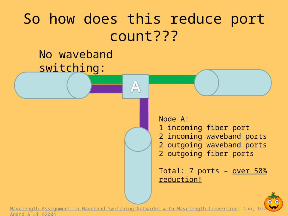
So how does this reduce port count???
Wavelength Assignment in Waveband Switching Networks with Wavelength Conversion; Cao, Qiao, Anand & Li ©2004
No waveband switching:
Node A: 1 incoming fiber port8 incoming wavelength ports8 outgoing wavelength ports2 outgoing fiber ports
Total: 19 ports
So how does this reduce port count???
Wavelength Assignment in Waveband Switching Networks with Wavelength Conversion; Cao, Qiao, Anand & Li ©2004
No waveband switching:
Node A: 1 incoming fiber port2 incoming waveband ports2 outgoing waveband ports2 outgoing fiber ports
Total: 7 ports – over 50% reduction!

A 3-Layer MG-OXC w/ WLC
Switch a wavelength
Switch a waveband
Switch a fiber
Wavelength conversion
Wavelength Assignment in Waveband Switching Networks with Wavelength Conversion; Cao, Qiao, Anand & Li ©2004

Wavelength Conversion
• Input/Output on different wavelength– Expensive, signal degradation
• In waveband switched networks:– Even if ports & converters available,
conversion requires demultiplexing to wavelength level.
Wavelength Assignment in Waveband Switching Networks with Wavelength Conversion; Cao, Qiao, Anand & Li ©2004

Waveband Assignment with Path Graph
• An algorithm to satisfy a new request– Minimize use of wavelength conversion– Maximize benefit of wavebanding
• Assumes:– Fixed routing– Intraband wavelength conversion
Wavelength Assignment in Waveband Switching Networks with Wavelength Conversion; Cao, Qiao, Anand & Li ©2004

• Our example:
Wavelength Assignment in Waveband Switching Networks with Wavelength Conversion; Cao, Qiao, Anand & Li ©2004
Waveband Assignment with Path Graph
Wavelength conversion
New Path
Existing Path
Fibers have 4 wavelengths in 2 bands

• Step 1: Split nodes by wavelength
Wavelength Assignment in Waveband Switching Networks with Wavelength Conversion; Cao, Qiao, Anand & Li ©2004
Waveband Assignment with Path Graph

• Step 2: Add converters
Wavelength Assignment in Waveband Switching Networks with Wavelength Conversion; Cao, Qiao, Anand & Li ©2004
Waveband Assignment with Path Graph

• Step 3: Draw available wavelengths
Wavelength Assignment in Waveband Switching Networks with Wavelength Conversion; Cao, Qiao, Anand & Li ©2004
Waveband Assignment with Path Graph

• Step 4: Assign weights
Wavelength Assignment in Waveband Switching Networks with Wavelength Conversion; Cao, Qiao, Anand & Li ©2004
Waveband Assignment with Path Graph
Wavelengths = λConverters = # wavelengths x # hops
1 1
2 2
3 3
4 44
3
2
16 16
16 16

• Step 5: Create logical source & destination
Wavelength Assignment in Waveband Switching Networks with Wavelength Conversion; Cao, Qiao, Anand & Li ©2004
Waveband Assignment with Path Graph
1 1
2 2
3 3
4 44
3
2
16 16
16 16
0
0
0
0
0
0
0
0

Dijkstra’s Algorithm:
• With the weighted links will:
1. Try to find a wavelength continuous path
2. Try to find a path using the minimum number of wavelength converters.
Wavelength Assignment in Waveband Switching Networks with Wavelength Conversion; Cao, Qiao, Anand & Li ©2004
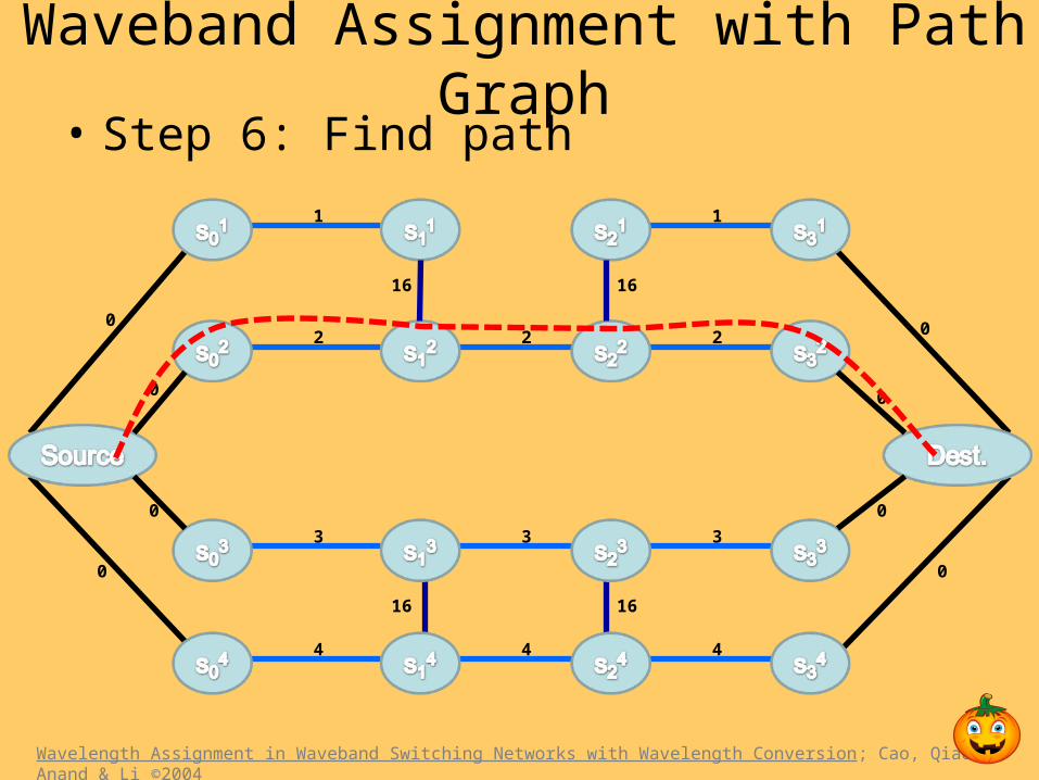
• Step 6: Find path
Wavelength Assignment in Waveband Switching Networks with Wavelength Conversion; Cao, Qiao, Anand & Li ©2004
Waveband Assignment with Path Graph
1 1
2 2
3 3
4 44
3
2
16 16
16 16
0
0
0
0
0
0
0
0

• Another Example:
Wavelength Assignment in Waveband Switching Networks with Wavelength Conversion; Cao, Qiao, Anand & Li ©2004
Waveband Assignment with Path Graph
1 1
2
3
4 4
3
16 16
16 16
0
0
0
0
0
0
0
0
16 16
16
16
16
16
16 16
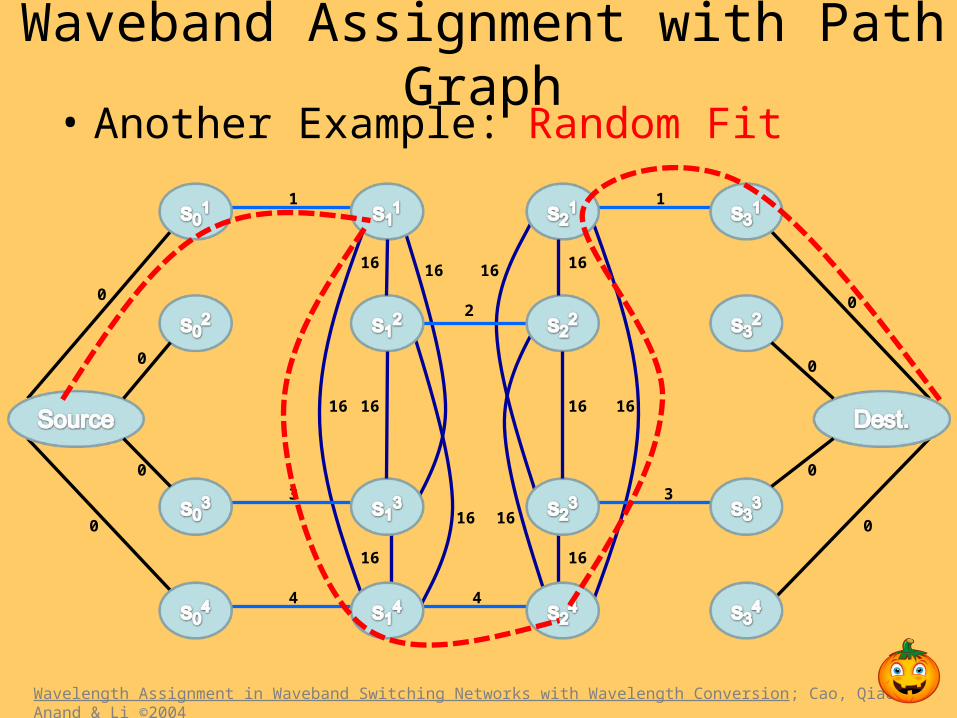
• Another Example: Random Fit
Wavelength Assignment in Waveband Switching Networks with Wavelength Conversion; Cao, Qiao, Anand & Li ©2004
Waveband Assignment with Path Graph
1 1
2
3
4 4
3
16 16
16 16
0
0
0
0
0
0
0
0
16 16
16
16
16
16
16 16

• Another Example: First Fit
Wavelength Assignment in Waveband Switching Networks with Wavelength Conversion; Cao, Qiao, Anand & Li ©2004
Waveband Assignment with Path Graph
1 1
2
3
4 4
3
16 16
16 16
0
0
0
0
0
0
0
0
16 16
16
16
16
16
16 16

• Another Example: Path Graph
Wavelength Assignment in Waveband Switching Networks with Wavelength Conversion; Cao, Qiao, Anand & Li ©2004
Waveband Assignment with Path Graph
1 1
2
3
4 4
3
16 16
16 16
0
0
0
0
0
0
0
0
16 16
16
16
16
16
16 16

Performance Results:
• With no conversion same as First Fit– Fixed routing – path already set
• Less blocking than First Fit or Random Fit
• Intraband conversion – nearly as good as full– High cost to demux two bands
• Large reduction in wavelength conversion
• Even better when not all fibers can be demuxed
Wavelength Assignment in Waveband Switching Networks with Wavelength Conversion; Cao, Qiao, Anand & Li ©2004

Waveband Aggregation techniques
• Source to End Switching
• Intermediate Waveband Switching – Intermediate to Destination (ITD-WBS) – Source to Intermediate (STI-WBS)* – Both-end-to-Intermediate (BETI-WBS)

Terms used
• Waveband granularity is defined as the number of wavelengths that can be grouped or aggregated into a waveband.
• Uniform waveband switching if the granularity of all the wavebands is an arbitrary constant g.

Wavelength Grooming
• Problem is to groom wavelengths into wavebands such that the number of ports saved is maximized.
• Depends on Uniform or Non-uniform waveband switching.
• Depends on the location of aggregation.

Intermediate-to-destination uniform waveband switching: (ITD-UWBS)
• Inputs : – Graph G=(V,E)
– Routed Demands Pd={p1,p2,……..,pk}
– Lightpaths for each demand• C={c1,c2 ……..ck}
– Destination : d– Waveband granularity : g

Limitations
• Connections that have the same destination.
• Complete set of paths can be partitioned into sub-sets based on their destination nodes.
• Waveband grooming only occurs among paths within a partition and not across partitions

Notations
• Waveband B of granularity g is denoted by
(Q, s, d, g)
• Q = {(p1, b1), (p2, b2), . . . (pm, bm)}
• Set of tuples (pi, bi) – pi is a routed-demand
– bi is the number if units (lightpaths) of the routed-demand.
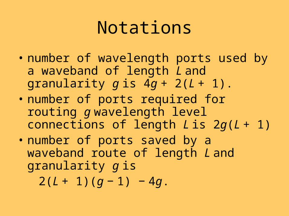
Notations
• number of wavelength ports used by a waveband of length L and granularity g is 4g + 2(L + 1).
• number of ports required for routing g wavelength level connections of length L is 2g(L + 1)
• number of ports saved by a waveband route of length L and granularity g is
2(L + 1)(g − 1) − 4g.

Algorithm (ITD-WBS)• Algorithm 1• 1: Input: (G, Pd, C)
– Pd = {p1, p2, . . . , pm}– C = {c1, c2, . . . , cm}
• 2: Output: Destination-rooted capacitated tree T• 3: compute graph T using paths in the set Pd• 4: transform T into a tree by deleting cycles in T and modifying
paths accordingly• 5: compute the height hi for each node i in the tree T• 6: initialize the residual capacity Rj of the leaf node j to ni where j the
source node of the path pi• 7: compute the residual capacity Ri of each intermediate node i as
the sum of the residual capacities of its child nodes

ABDest
Source2
Source1
4
9
9
9
4 4
Paths
p1 : dabs1; c1 = 4
p2 : dbas2; c2 = 9
Subset of Graphwith Cycles
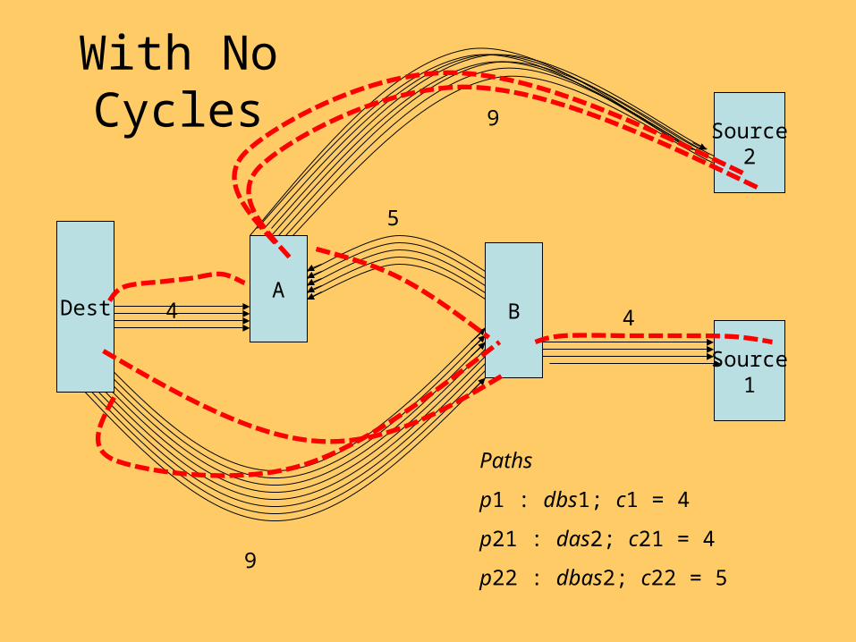
ABDest
Source2
Source1
9
9
5
4 4
Paths
p1 : dbs1; c1 = 4
p21 : das2; c21 = 4
p22 : dbas2; c22 = 5
With No Cycles

Dest
Source21
9
4
54
Assign Heights
Source1
Source22
B
A
4
5
A
G = 3
0
1
1
2
2
3
2

Dest
Source21
Calculate Residual Capacities
Source1
Source22
A
A
G = 3
0,13
1,4
1,9
2,5
2,4
3,5
2,4
B

Algorithm 2• 1: Input:(G, Pd, C, g)• 2: Output: Waveband set B • 3: run Algorithm 1 on input (G, Pd, C)• 4: for i = h; i ≤ 2; i−− do• 5: for each u where hu = i, and Ru ≥ g do• 6: if ((Su = 2(i + 1)(g − 1) − 4g) > 0) then• 7: form waveband B = (Q, u, d, g) from node u to root node d and
add to B • 8: update the residual capacities Ru of all the nodes along the paths
included in the waveband• 9: end if• 10: end for• 11: end for

Dest
Source21
Iteration 1
Source1
Source22
A
A
G = 3
0,13
1,4
1,9
2,5
2,4
3,5
2,4
B

Source21
Iteration 2
Source1
Source22
A
A
G = 3
0,10
1,4
1,6
2,2
2,4
3,2
2,4
B
Dest
Waveband:
B1=s2-a-b-d

Source21
Iteration 3
Source1
Source22
A
G = 3
0,7
1,4
1,3
2,2
2,1
3,1
2,4
B
Waveband:
B1=s2--a--b---d
B2= s1—b---d
A
Dest

Source21
Iteration 4
Source1
Source22
A
G = 3
0,4
1,1
1,3
2,2
2,1
3,2
2,1
B
Waveband:
B1=s2--a--b---d
B2= s1—b---d
B3= s2---a---d
A
Dest

Source21
Iteration 5
Source1
Source22
A
G = 3
0,1
1,1
1,0
2,2
2,1
3,2
2,1
B
Waveband:
B1=s2--a--b---d B4= b-d
B2= s1—b---d
B3= s2---a---d
A
Dest

Algorithm for BETI waveband switching
• Create a Destination-rooted capacitated tree and Source rooted capacitated tree.

Algorithm 3 The Initialization Algorithm for the BETI problem.
• 1: Input: (G, P,C)• 2: compute graphs Tt and Ts using paths in the set P• 3: add super destination node d and super source node s to trees Tt
and Ts respectively• 4: add edges from node d to all the destination nodes in tree Tt• 5: add edges from node s to all the source nodes in tree Ts• 6: transform Tt and Ts into a trees by deleting cycles in Tt and ts
and modifying paths accordingly• 7: compute the height hi for each node i in the tree T• 8: initialize the residual capacity Rj of the leaf node sj of the tree Tt
to ni where sj the source node of the path pi• 9: initialize the residual capacity Rj of the leaf node tj of the tree Ts
to ni where tj the source node of the path pi• 10: compute the residual capacity Ri of each intermediate node of
the trees Tt and Ts as the sum of the residual capacities of its child nodes

• Algorithm 4 The BETI Algorithm for computing the wavebands.
• 1: Input:(G, P,C)• 2: Output: Waveband set B 3: run Algorithm 3 on input (G, P,C) to
compute trees Tt and Ts• 4: let ht and hs be the heights of the trees• 5: let h be the maximum of the heights hd and ht• 6: for i = h; i ≤ 2; i−− do• 7: for each u in Tt and Ts where hu = i in the corresponding tree,
and Ru ≥ g do• 8: if ((Su = 2(i + 1)(g − 1) − 4g) > 0) then• 9: form waveband B = (Q, u, d, g) from node u to root node d/s
corresponding to tree Tt/Ts and add to B 10: update the residual capacities Ru of all the nodes along the paths in included in the waveband in both the trees Tt and Ts
• 11: end if• 12: end for• 13: end for

?

HAPPY HALOWEEN

BACKUP

Wavelength Assignment Methods:
• Always start with lowest wavelength
• If there is a continuous path – TAKE IT!
• Else:– Random fit: Randomly choose next wavelength– First fit: Choose the first available wavelength– Path Graph: Use dijkstra’s algorithm to find path
Wavelength Assignment in Waveband Switching Networks with Wavelength Conversion; Cao, Qiao, Anand & Li ©2004

So how does this reduce port count???
• An simple example:– 1 fiber – 64 wavelengths – 8 bands– Need to drop 1 wavelength
Wavelength Assignment in Waveband Switching Networks with Wavelength Conversion; Cao, Qiao, Anand & Li ©2004
Traditional OXC Waveband Switching
BXC Ports: 0 8 in – 8 out
OXC Ports: 64 in – 64 out 8 in – 8 out
Total: 128 32


