CSA FRAME 1 PUMP RANGE - hmdkontro.com
16
1 CSA FRAME 1 PUMP RANGE (60HZ) Magnet Drive end suction centrifugal pumps in accordance to: ASME B73.3-2015
Transcript of CSA FRAME 1 PUMP RANGE - hmdkontro.com

1
CSAFRAME 1 PUMP RANGE (60HZ)Magnet Drive end suction centrifugal pumps in accordance to:ASME B73.3-2015
2
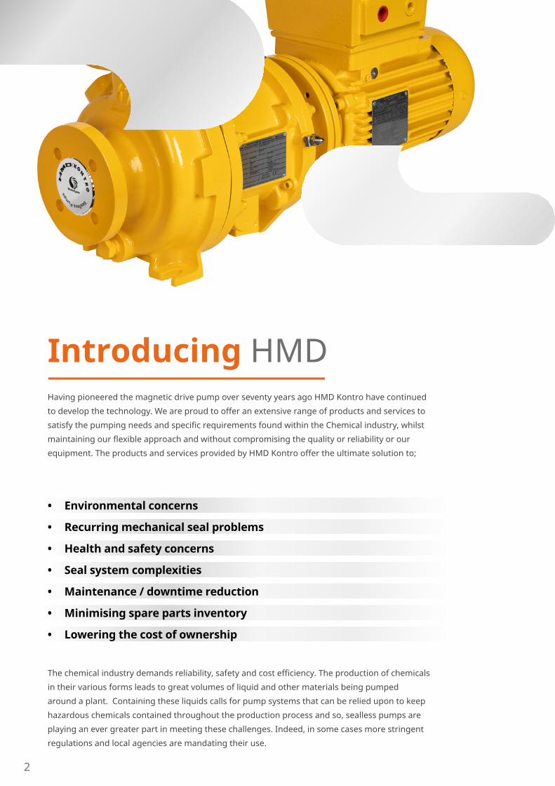
Having pioneered the magnetic drive pump over seventy years ago HMD Kontro have continued
to develop the technology. We are proud to offer an extensive range of products and services to
satisfy the pumping needs and specific requirements found within the Chemical industry, whilst
maintaining our flexible approach and without compromising the quality or reliability or our
equipment. The products and services provided by HMD Kontro offer the ultimate solution to;
• Environmental concerns
• Recurring mechanical seal problems
• Health and safety concerns
• Seal system complexities
• Maintenance / downtime reduction
• Minimising spare parts inventory
• Lowering the cost of ownership
The chemical industry demands reliability, safety and cost efficiency. The production of chemicals
in their various forms leads to great volumes of liquid and other materials being pumped
around a plant. Containing these liquids calls for pump systems that can be relied upon to keep
hazardous chemicals contained throughout the production process and so, sealless pumps are
playing an ever greater part in meeting these challenges. Indeed, in some cases more stringent
regulations and local agencies are mandating their use.
Introducing HMD
3
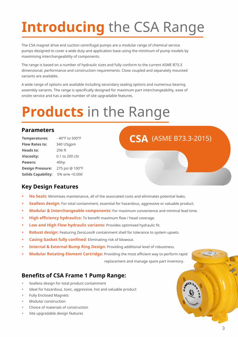
The CSA magnet drive end suction centrifugal pumps are a modular range of chemical service pumps designed to cover a wide duty and application base using the minimum of pump models by maximising interchangeability of components.
The range is based on a number of hydraulic sizes and fully conform to the current ASME B73.3 dimensional, performance and construction requirements. Close coupled and separately mounted variants are available.
A wide range of options are available including secondary sealing options and numerous bearing assembly variants. The range is specifically designed for maximum part interchangeability, ease of onsite service and has a wide number of site upgradable features.
Products in the Range
CSA
Introducing the CSA Range
Temperatures: - 40°F to 500°F
Flow Rates to: 340 USgpm
Heads to: 296 ft
Viscosity: 0.1 to 200 cSt
Powers: 40hp
Design Pressure: 275 psi @ 100°F
Solids Capability: 5% w/w <0.006’
Parameters
• No Seals: Minimises maintenance, all of the associated costs and eliminates potential leaks.
• Sealless design: For total containment, essential for hazardous, aggressive or valuable product.
• Modular & Interchangeable components: For maximum convenience and minimal lead time.
• High efficiency hydraulics: To benefit maximum flow / head coverage.
• Low and High Flow hydraulic variants: Provides optimised hydraulic fit.
• Robust design: Featuring ZeroLoss® containment shell for tolerance to system upsets.
• Casing Gasket fully confined: Eliminating risk of blowout.
• Internal & External Bump Ring Design: Providing additional level of robustness.
• Modular Rotating Element Cartridge: Providing the most efficient way to perform rapid
replacement and manage spare part inventory.
Key Design Features
• Sealless design for total product containment
• Ideal for hazardous, toxic, aggressive, hot and valuable product
• Fully Enclosed Magnets
• Modular construction
• Choice of materials of construction
• Site upgradable design features
Benefits of CSA Frame 1 Pump Range:
(ASME B73.3-2015)

4
Fully self venting design
CSA Pump range
Single piece Bush Holderfor optimized InternalBearing aligment
Site replaceable Neck Rings
Casings interchangeable withexisting GSA designs
Wide range of hydraulics includingHigh Flow (H) andLow Flow (L) variants
Fully dimensionallycompliant to ASMEstandards
Choice of CasingDrain options
Site serviceable InternalBearing System - no special tools or hot work needed
Optional Internal Bearing designs: SiC/ SiCSic / CarbonSiC / CMC
Fully enclosed andprotected Magnets
Proven Internal Bearing Feed System

5
Magnetic Coupling Housingwith Pre-drilled and plugged RTD port and optional Liquid Sensing port
Back pull out design
Optional Secondary Controlof Containment variants available on Separately Mounted and Close Coupled designs
Magnetic Drain Plug and Bullseye sight glass
Increased Oil Sump Capacity
External Bearing Assembly- Non - overfilling design
External Drive Shaft Seal options- Labyrinth, Inpro or Labtecta
Optional External Lubrication Systems - Constant Level Oiler, Purge Oil Mist ot Oil Mist
Integrated Vortex breaker to further improve robustness
Optimised Magnetic Couplings sized for specific application requirements
Alloy C or High EfficiencyZeroLoss® Containment Shells
Internal and External Bump Ring design
6
1.2.
3.
4.
5.
6.
7.
8.
9. 10.
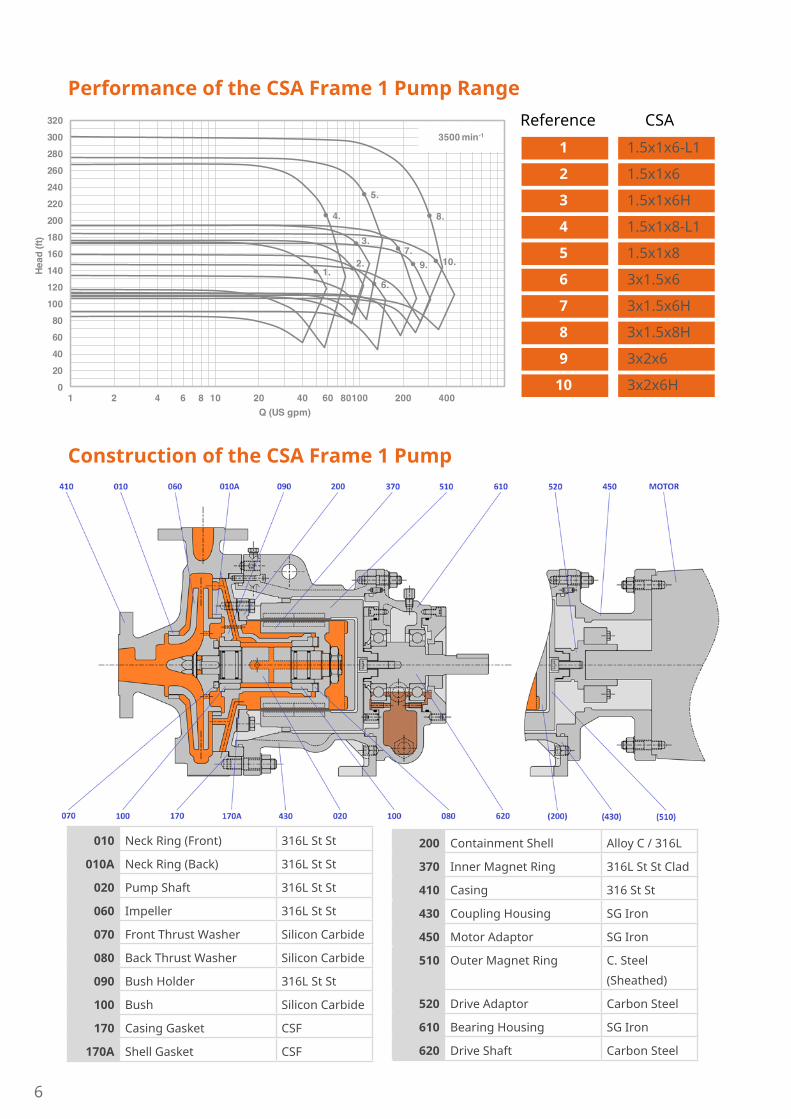
1 2 4 6 8 10 20 40 60 80100 200 400Q (US gpm)
3500 min-1
020406080
100120140160180200220240260280300320
Head
(ft)
010 Neck Ring (Front) 316L St St
010A Neck Ring (Back) 316L St St
020 Pump Shaft 316L St St
060 Impeller 316L St St
070 Front Thrust Washer Silicon Carbide
080 Back Thrust Washer Silicon Carbide
090 Bush Holder 316L St St
100 Bush Silicon Carbide
170 Casing Gasket CSF
170A Shell Gasket CSF
200 Containment Shell Alloy C / 316L
370 Inner Magnet Ring 316L St St Clad
410 Casing 316 St St
430 Coupling Housing SG Iron
450 Motor Adaptor SG Iron
510 Outer Magnet Ring C. Steel
(Sheathed)
520 Drive Adaptor Carbon Steel
610 Bearing Housing SG Iron
620 Drive Shaft Carbon Steel
Reference CSA
1 1.5x1x6-L1
2 1.5x1x6
3 1.5x1x6H
4 1.5x1x8-L1
5 1.5x1x8
6 3x1.5x6
7 3x1.5x6H
8 3x1.5x8H
9 3x2x6
10 3x2x6H
Performance of the CSA Frame 1 Pump Range
Construction of the CSA Frame 1 Pump

7
Separately Mounted (Bareshaft)
SeparatelyMounted
CloseCoupled
(Dimensions are for guidance only)
CPCPeD2E1FHOUV XY
17.5195.2567.25 0.625 11.75 0.875 2 6.54
Size All Frame 1
Motor Frame143TC – 184TC213TC – 256TC284TSC – 326TC
A HA HB HT HTe HD HE HF HG HH HL HP12 14 43 5.5 4 9 4.5 40.5 3 0.75 4.5 1.2515 17 52 5.5 4 10.5 6 49.5 3.5 0.75 4.5 1.25 18 20 57 5.5 4 12.5 7.5 54.5 4 0.75 4.5 1.25
Motor Frame143TC – 145TC182TC – 184TC213TC – 215TC254TC – 256TC
284TSC – 286TSC
CP A HA HB HD HE HF HG HH HL HP15.14 12 14 32 9 4.5 29.5 3 0.75 4.5 1.2515.65 12 14 32 9 4.5 29.5 3 0.75 4.5 1.2516.17 15 17 41 10.5 6 38.5 3.5 0.75 4.5 1.2516.80 15 17 41 10.5 6 38.5 3.5 0.75 4.5 1.2516.05 18 20 44 12.5 7.5 41.5 4 0.75 4.5 1.25
Dimensions of CSAFrame 1 Pump

8
Metallic and ZeroLoss® shell options - interchangeable
• 275 psi Design pressure• Proven welded construction• High strength alloy C276 tube • Suitable for process temperatures up to 500°F • Range of SmCo Magnetic Couplings to suit
specific duty requirements• In-built vortex breaker
Metallic Shell• 275 psi Design pressure• PEEK Composite design• Suitable for process temperatures up to 250°F• High Power NdFeB Magnetic Coupling• High efficiency – no induction losses,
no heat into process liquid • Provides highest process upset tolerance• In-built vortex breaker
ZeroLoss® Shell
Site Serviceable Design Site replaceable Cartridge design ensures maximum up time and minimum disruption in the unlikely event of a breakdown.
Comprising of wetted parts (not casing):• Impeller• Shaft• Internal Bush Holder and Bearings• Containment Shell• Inner Rotor
Designed to be serviced / overhauled on site:• No special tools• No hot working• Simple to decontaminate• No special motor decontamination needed
Single piece Bush Holder – easily serviced on site:• No hot working• No special tools• In built bush retention features
Radial and Thrust Bearings interchangeable across entire Frame 1 range
Site serviceable Internal Product Lubricated Bearing assembly:
Optional Internal Bearing Materials• SiC vs Sic (Standard Build)• SiC vs Carbon (Variant for low lubricity conditions)• SiC vs Ceramic Matrix Composite (CMC) thrust
bearing (Variant for marginal applications)

9
…designed for maximum service life and ease of maintenance
External Bearing Assembly
• Non-overfilling design• Large sump capacity• Magnetic sump plug• Bulls eye style sight glass• External bearing isolator options
available
External bearing assembly:• Oil bath (standard)• Oil bath and constant level oiler• Purge Oil mist• Pure Oil mist
Available lubrication systems:
Extended Spacer and Shaft design for increased process temperatures from 400°F to 500°F.
Standard design Non-overfilling designExtended CPe design
• Choice of secondary control or secondary
containment systems
• Secondary housing designed for 275 psi pressure
conditions
• O-rings to completely seal secondary housing
• Provision for Liquid Sensing probe or Pressure
Sensing device to be fitted in Secondary housing
• Fully compliant to ASME requirements
• Available on both Close Coupled and Separately
Mounted design configurations
• Extended Spacer and Shaft design utilised on
Separately Mounted designs
• For process temperatures < 400°F
Secondary Control and Containment Options:
…when product integrity cannot be compromised
Close Coupled Secondary Control
Separately Mounted Secondary Containment
Additional Security

10
Pump End Interchangeability Matrix
11
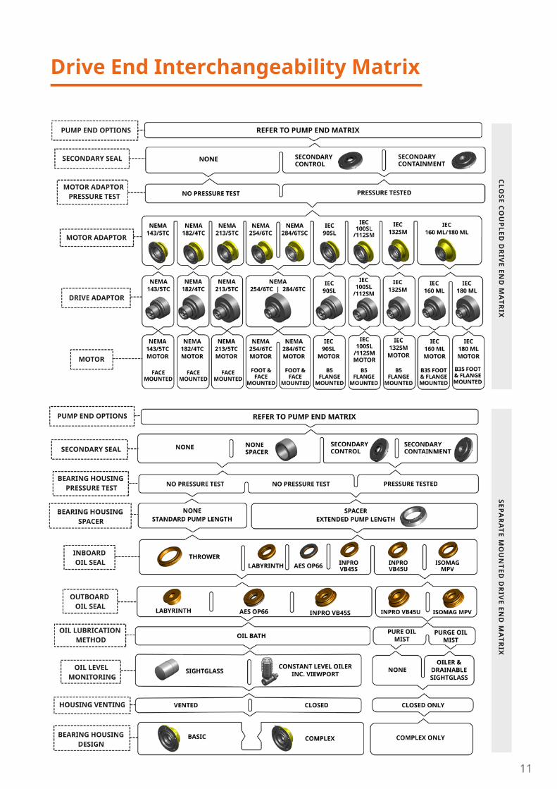
Drive End Interchangeability Matrix

12
CasingSuction and discharge flanges are designed in accordance
with the following standards:
ASME B16.5 Class 150lb Machined with 0.006’’
high raised face having a continuous spiral groove
Flange LoadingsAllowable flange loadings imposed
by the pipework are in accordance
with ANSI/HI 9.6.2.
Options
Materials of Construction:316L Stainless Steel (standard)
Alloy C (optional variant)
Alloy 20 (optional variant)
Containment Shells:Metallic Construction (- 40°F to 500°F)
High Efficiency ZeroLoss® PEEK (- 40°F to 250°F)
Internal Bearings:Silicon Carbide vs Silicon Carbide (standard)
Carbon vs Silicon Carbide (optional)
Silicon Carbide vs CMC (optional)
Casings Drain:No Drain or 1⁄2” NPT Plugged
Gaskets:Compressed Synthetic Fibre, PTFE or Graphite
Mounting Configuration:Close Coupled:
(NEMA C-Face or C-Face/Foot Flange Mounted
Motor)
Separately Mounted:
(NEMA Foot Mounted Motor and Flexible
Coupling)
Constructional Variants:Secondary Containment
Secondary Control
Oil Bath / Oil Mist Lubrication of external
bearing assembly
400 - 500°F Thermal Break
Instrumentation:Power Sensing, Temperature Sensing and
VapourView®
A wide variety of options are available:
Flanges and Connections
13
Value PropositionHMD Kontro high quality Sealless Pumps move hazardous and high value liquids with simplicity
and in complete safety whilst ensuring maximum production output and profitability.
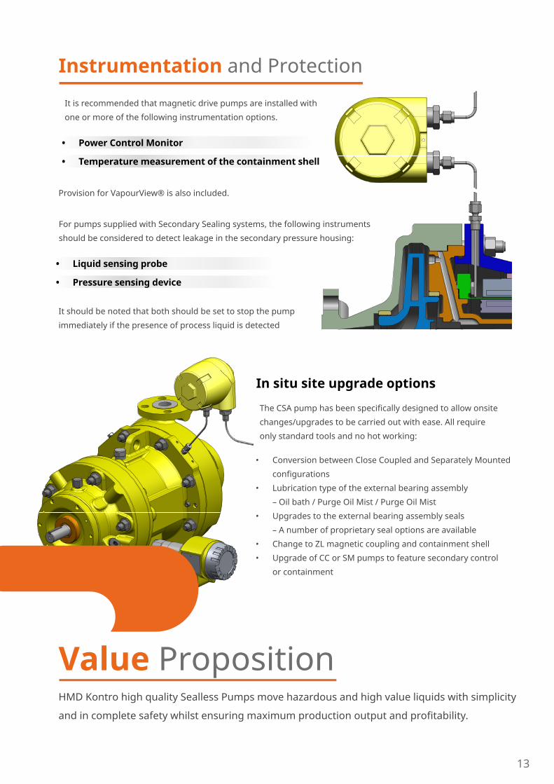
Instrumentation and Protection
It is recommended that magnetic drive pumps are installed with
one or more of the following instrumentation options.
• Power Control Monitor
• Temperature measurement of the containment shell
Provision for VapourView® is also included.
For pumps supplied with Secondary Sealing systems, the following instruments
should be considered to detect leakage in the secondary pressure housing:
• Liquid sensing probe
• Pressure sensing device
It should be noted that both should be set to stop the pump
immediately if the presence of process liquid is detected
In situ site upgrade options
The CSA pump has been specifically designed to allow onsite
changes/upgrades to be carried out with ease. All require
only standard tools and no hot working:
• Conversion between Close Coupled and Separately Mounted
configurations
• Lubrication type of the external bearing assembly
– Oil bath / Purge Oil Mist / Purge Oil Mist
• Upgrades to the external bearing assembly seals
– A number of proprietary seal options are available
• Change to ZL magnetic coupling and containment shell
• Upgrade of CC or SM pumps to feature secondary control
or containment

14
THINKSEALLESSSealless pumps are easy to maintain, have few working parts, no potential leak paths and no support systems to design, install and maintain. When selecting a sealless pump over a mechanical sealed pump it doesn’t just come just down to the long term cost benefits. The sealless technology is by design, the right choice for situations involving high temperatures, high viscosity, high pressures and volatile substances for many more reasons than just the life time cost.
SEALLESSSYSTEM
What is a sealless magnetic drive pump? A sealless pump is essentially a conventional centrifugal pump without packed glands or mechanical seals. The dynamic seal that would normally be used to seal the impeller shaft is instead replaced by a static containment shell -- or shroud -- to form a completely sealed liquid end or pressure boundary.
Why are they sealless?Mechanical seals are widely regarded as the weakest point in any pumping system using them, according to a report by the Uk Health and Safety Executive, they account for 80% of all pump failures, the remainder being leakage through static seals such as gaskets / O rings and bearing failure. It follows that if you eliminate the problem, you eliminate the failures and save costs.
Sealless pumps don’t leak, meaning that they can help reduce process inefficiencies, maximize output and minimize the risks posed to your process environment by hazardous and volatile materials.
“We find HMD Kontro pumpslast over 20 years but sealedpumps need to be replaced in 10 or 12 years.” Pharmaceutical manufacturer
SEALLESSSELECT
For situations involving high temperatures, high viscosity, high pressures and volatile substances, sealless magnetic drive pumps are the clear choice. Specifically, when it comes to applications that involve toxic, fine, corrosive and aggressive liquids that must be handled, our sealless magnetic drive pumps deliver the rock solid performance that engineers demand and that industrial regulations require.
• Chemical
• Pharmaceutical
• Fine chemical
• Agrichemical
• Oil & Gas (upstream and downstream offshore and onshore)
• Food & beverage production
• And across many industrial operations
15
Typical applications are for fluids presenting difficult and/or costly sealing challenges:
• Acids • Solvents • High Melting Point Liquids • Heat Transfer Fluids • Volatile liquids - LPG, Processed
hydrocarbons, Crude oil • Hazardous liquids • Expensive Fluids • Fluids under pressure • Toxic • Pungent • Corrosive • Radioactive • Crystallising
The latest parameters at which magnetic drive pumps can operate may surprise you:
• Temperature - Down to minus 80oC / 112oF
• Up to 450oC / 840oF Torque Ring Design
• Up to 315oC / 600oF Synchronous Design
• Flow Rates – Up to 690m3/hour / 3000 USGPM
• Heads – Up to 240m / 767’ differential
• Viscosity – Maximum 200 cSt
• Pressure - Up to 185 Bar / 2683 psi
• Solids - Up to 5%, with a particle size of 150 microns
• Up to 8% and less than 250 microns with filtration
• Power - 400kW 50hz / 530hp 60hz
• peed Range 1450 – 3500 RPM
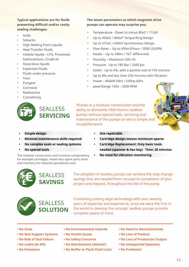
SEALLESSSERVICING
Thanks to a modular construction and the ability to dismantle HMD Kontro sealless pumps without special tools, servicing and maintenance of the pumps on site is simple and straightforward.
• Simple design • Minimal maintenance skills required • No complex seals or sealing systems • No special tools
• Site repairable • Cartridge design means minimum spares • Cartridge Replacement: Only basic tools
needed (spanner & hex key) Time: 20 minutes • No need for vibration monitoring The modular construction and common componentry,
for example cartridges, means less spare parts stock and inventory for reduced operational costs
SEALLESSSAVINGS£
$ €$ The adoption of sealless pumps can achieve the step change savings that are needed from concept to completion of your project and beyond, throughout the life of the pump.
SEALLESSSOLUTION
Combining cutting edge technology with over seventy years of expertise and experience, since we were the first in the world to develop the concept, sealless pumps provide complete peace of mind.
• No Seals • No Seal Support Systems • No Risk of Seal Failure • No Leaks (At All!) • No Emissions
• No Environmental Hazards • No Health Issues• No Safety Concerns • No Maintenance (Almost!) • No Buffer or Flush Fluid Costs
• No Need to Decontaminate • No Loss of Product • No Loss of Production Output • No Unexpected Expenses • No Problems!

16
Although our pumps only require minimal maintenance, that
does not mean there is no after sales service from HMD Kontro.
Quite the opposite in fact.
Our own After Sales team, together with our channel partners
around the world, can help to optimise the performance and
through life experience of using HMD Kontro pumps. From
assisting with installation and commissioning, including
ensuring smooth contract execution and swift provision of all
the appropriate documentation, through to optimising your
spares inventory and operating efficiency using the benefit of
our experience.
Extending MTBF (mean time between failure) and providing you
with the appropriate parts to effect fast maintenance and quick
replacement where necessary, will significantly assist in reducing
downtime and minimising through life costs, which are already
inherently low with an HMD Kontro pump.
To learn more about why sealless is so suitable for your application,
please contact us, either directly or through your country partner,
details of which can be found on www.sundyne.com. We look
forward to helping sealless be of service to you.
SeallessService
www.hmdkontro.com
HMD Kontro Sealless Pumps Marshall RoadHampden Park Industrial EstateEastbourne, East Sussex, BN22 9ANUnited KingdomPhone: +44 (0)1323 452000Fax: +44 (0)1323 503369Email: [email protected]
Sundyne HeadquartersSundyne LLC 14845 West 64th AvenueArvada, Colorado 80007USA1-866-SundynePhone: 1 303 425 0800Fax: 1 303 940 2911www.sundyne.com
Sundyne France Sundyne International S.A13-15, Bld, Eiffel - B.P. 3021604 Longvic CedexFrancePhone: +33 (0)3 80 38 33 00Fax: +33 (0)3 80 38 33 66
Sundyne SpainSundyne Marelli Bombas, S.R.L. Ctra, Madrid-Toledo, Km. 30.845200 IllescasToledo, SpainPhone: +34 925 53 45 00Fax: +34 925 51 16 00
All information provided is subject to change without notice.
© 2014 Sundyne, LLCAll Rights Reserved. Other logos and trandemark names are property of the respective owners.
HMD Kontro
CSA Frame 1 Pump Range (60HZ)ASME B73.3-2015
CSA Frame 1 60Hz Brochure 1.1 3/21 Eng.