CS343: Data Communication
28
CS343: Data Communication Switched Communication Network by Dr. Manas Khatua Assistant Professor Dept. of CSE IIT Guwahati E-mail: [email protected]
Transcript of CS343: Data Communication

CS343: Data Communication
Switched Communication Network
by
Dr. Manas KhatuaAssistant Professor
Dept. of CSEIIT Guwahati
E-mail: [email protected]
Switched Communication Network
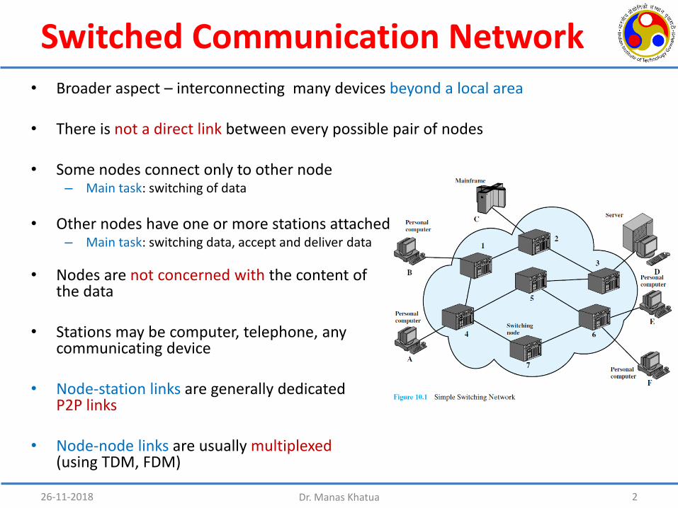
• Nodes are not concerned with the content of the data
• Stations may be computer, telephone, any communicating device
• Node-station links are generally dedicated P2P links
• Node-node links are usually multiplexed(using TDM, FDM)
26-11-2018 Dr. Manas Khatua 2
• Broader aspect – interconnecting many devices beyond a local area
• There is not a direct link between every possible pair of nodes
• Some nodes connect only to other node– Main task: switching of data
• Other nodes have one or more stations attached – Main task: switching data, accept and deliver data

Why Switching?• Interconnecting many devices – forms the Switched Network
• A switch transfers signals from one input port to an appropriate output.
• A basic problem is then how to transfer traffic to the correct output port.
• Solution:– In the early telephone network, operators closed circuits manually. – In modern circuit switches, this is done electronically in digital switches.
• If no circuit is available when a call is made, it will be blocked (rejected). • When a call is finished a connection teardown is required to make the circuit available
for another user.
• So, the basic function of any switch is to set up and release connections between transmission channels.
• Two different switching technologies over the network:– Circuit switching– Packet switching
26-11-2018 Dr. Manas Khatua 3
Circuit Switching
26-11-2018 Dr. Manas Khatua 4
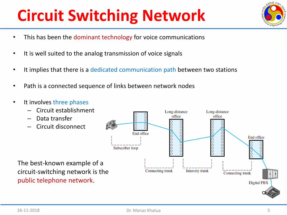
Circuit Switching Network• This has been the dominant technology for voice communications
• It is well suited to the analog transmission of voice signals
• It implies that there is a dedicated communication path between two stations
• Path is a connected sequence of links between network nodes
• It involves three phases– Circuit establishment– Data transfer– Circuit disconnect
26-11-2018 Dr. Manas Khatua 5
The best-known example of a circuit-switching network is the public telephone network.

Cont…• Examples of circuit switching networks
– Public telephone network– Private branch exchange (PBX) system– Data switch system
• In circuit switching, the path is established before data transmission begins.– Sometimes less efficient as channel capacity remains unused– There is connection establishment delay prior to data transfer
26-11-2018 Dr. Manas Khatua 6
• Architectural components in public telecommunication network• Subscribers• Subscriber line• Exchanges• Trunks

Circuit Switching Concepts• Function of the digital switch
– provide a transparent signal path between any pairof attached devices
• The control unit performs 3 general tasks– establishes connections– maintain the connection– tear down the connection
• The network interface element represents– Functions and hardware needed to connect digital
devices
• Blocking or non-blocking– Blocking occurs when the network is unable to
connect two stations because all possible paths between them are already in use
• Switching techniques internal to a single node– Space Division Switching– Time Division Switching
26-11-2018 Dr. Manas Khatua 7

Space Division Switching• Originally developed for analog signal
• the signal paths are physically separate from one another (divided in space).
• The basic building block of the switch is– a metallic crosspoint OR semiconductor
gate that can be enabled and disabled by a control unit.
• Interconnection is possible between any two lines by enabling the appropriate crosspoint.
• Limitations:– crosspoints grows with the square of the
number of stations– crosspoints are inefficiently utilized– single point failure (loss of crosspoint)
26-11-2018 Dr. Manas Khatua 8

Cont…• To overcome these limitations, multiple-stage switches are employed
• the total number of crosspoints for 10 stations is reduced from 100 to 48.
26-11-2018 Dr. Manas Khatua 9
Advantage:• increasing crossbar
utilization• increasing reliability as
multiple paths between two endpoints
Disadvantage:• more complex control• may be blocking (single
stage crossbar switch is strict sense nonblocking)

Blocking vs Non-blocking
Signals A, B, C, D are routed but signal E is blocked even though output port in egress switch remains unused.
26-11-2018 Dr. Manas Khatua 10
After D, in purple, is rerouted, signal E can be routed and all the additional signals plus E are connected
• strict-sense non-blocking meaning that an unused input on an ingress switch can always be connected to an unused output on an egress switch, without having to re-arrange existing calls

Clos Networks
• If there are a total of N input lines , then r=N/n
• Each ingress stage crossbar switch has m outlets, and there are m middle stagecrossbar switches.
• There is exactly one connection between each ingress stage switch and each middle stage switch.
• There are r egress stage switches, each with m inputs and n outputs.
• Each middle stage switch is connected exactly once to each egress stage switch.
26-11-2018 Dr. Manas Khatua 11
• Clos networks are defined by three integers n, m, r. Three stages: ingress, middle, egress
• n represents the number of inputs which feed into each of r ingress stage crossbar switches.
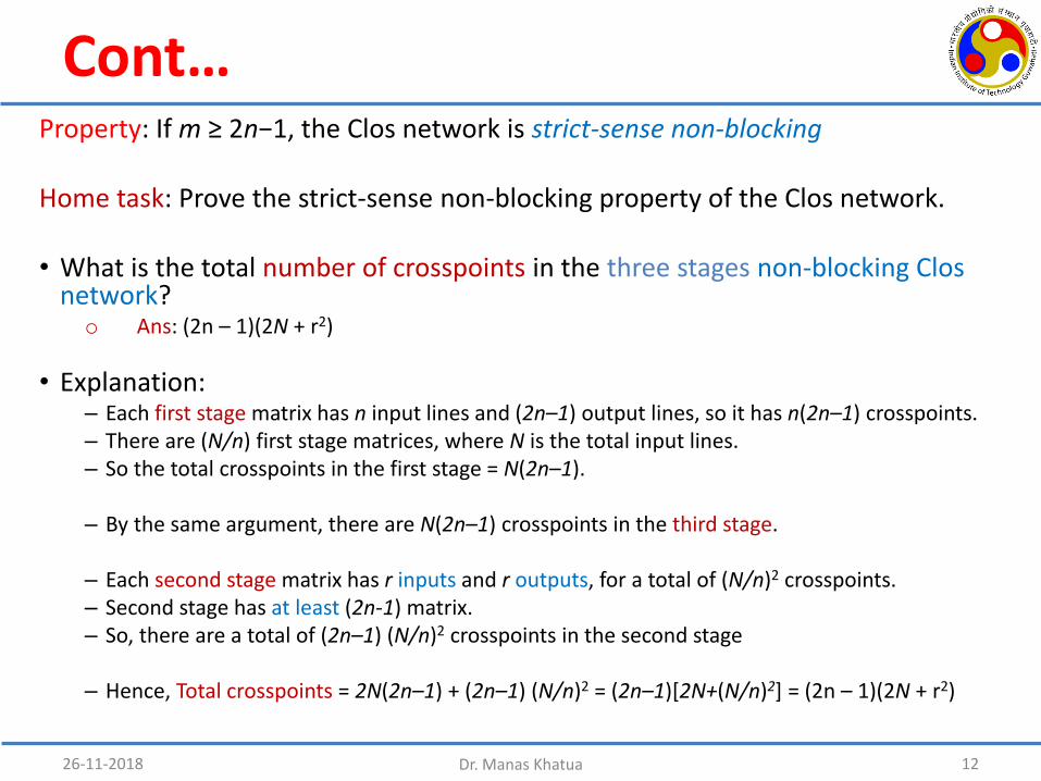
Cont…Property: If m ≥ 2n−1, the Clos network is strict-sense non-blocking
Home task: Prove the strict-sense non-blocking property of the Clos network.
• What is the total number of crosspoints in the three stages non-blocking Clos network?o Ans: (2n – 1)(2N + r2)
• Explanation:– Each first stage matrix has n input lines and (2n–1) output lines, so it has n(2n–1) crosspoints.– There are (N/n) first stage matrices, where N is the total input lines.– So the total crosspoints in the first stage = N(2n–1).
– By the same argument, there are N(2n–1) crosspoints in the third stage.
– Each second stage matrix has r inputs and r outputs, for a total of (N/n)2 crosspoints. – Second stage has at least (2n-1) matrix. – So, there are a total of (2n–1) (N/n)2 crosspoints in the second stage
– Hence, Total crosspoints = 2N(2n–1) + (2n–1) (N/n)2 = (2n–1)[2N+(N/n)2] = (2n – 1)(2N + r2)
26-11-2018 Dr. Manas Khatua 12
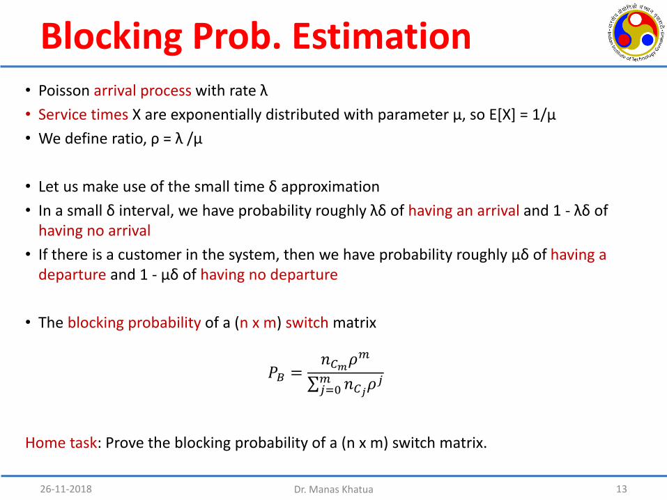
Blocking Prob. Estimation• Poisson arrival process with rate λ
• Service times X are exponentially distributed with parameter µ, so E[X] = 1/µ
• We define ratio, ρ = λ /µ
• Let us make use of the small time δ approximation
• In a small δ interval, we have probability roughly λδ of having an arrival and 1 - λδ of having no arrival
• If there is a customer in the system, then we have probability roughly µδ of having a departure and 1 - µδ of having no departure
• The blocking probability of a (n x m) switch matrix
26-11-2018 Dr. Manas Khatua 13
𝑃𝐵 =𝑛𝐶𝑚𝜌
𝑚
σ𝑗=0𝑚 𝑛𝐶𝑗𝜌
𝑗
Home task: Prove the blocking probability of a (n x m) switch matrix.
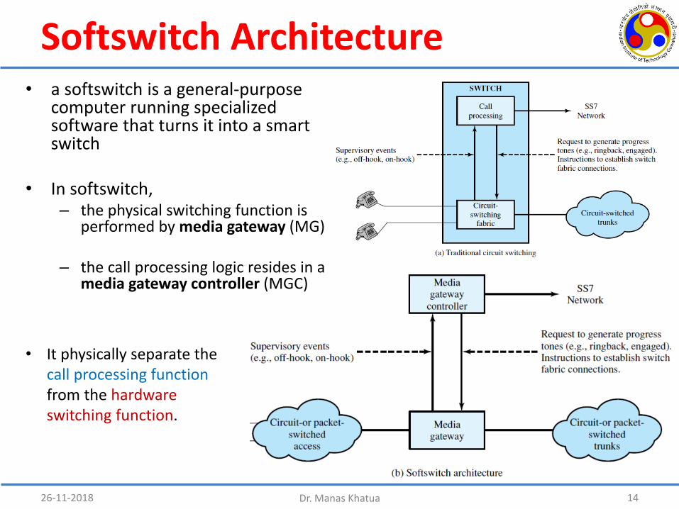
Softswitch Architecture• a softswitch is a general-purpose
computer running specialized software that turns it into a smart switch
• In softswitch, – the physical switching function is
performed by media gateway (MG)
– the call processing logic resides in a media gateway controller (MGC)
26-11-2018 Dr. Manas Khatua 14
• It physically separate the call processing functionfrom the hardware switching function.

Packet Switching
26-11-2018 Dr. Manas Khatua 15

Packet Switching
• Advantages of Packet Switching over Circuit Switching
– Higher line efficiency, because a single node-to-node link can be dynamically shared by many packets over time
– Two end stations of different data rates can exchange packets
– Under heavy traffic condition, circuit switching refuses connection, but packet allows with higher delay
– Priorities can be applied
26-11-2018 Dr. Manas Khatua 16
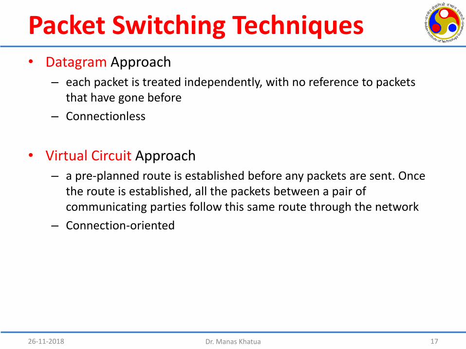
Packet Switching Techniques• Datagram Approach
– each packet is treated independently, with no reference to packets that have gone before
– Connectionless
• Virtual Circuit Approach– a pre-planned route is established before any packets are sent. Once
the route is established, all the packets between a pair of communicating parties follow this same route through the network
– Connection-oriented
26-11-2018 Dr. Manas Khatua 17

Virtual Circuit & Datagram Approaches
26-11-2018 Dr. Manas Khatua 18
Virtual Circuit
Datagram Approach
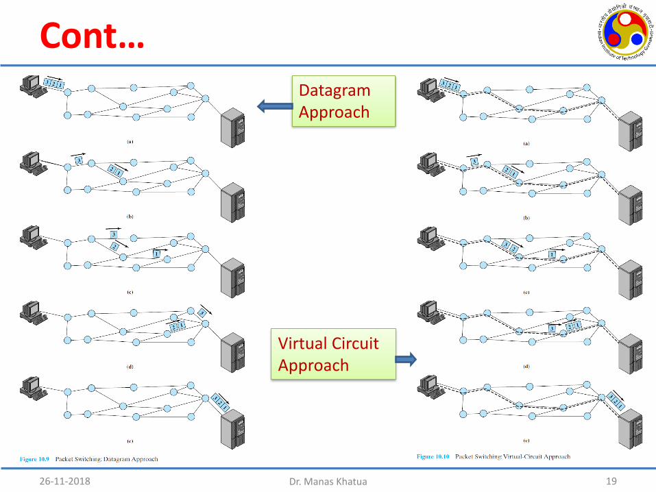
Cont…
26-11-2018 Dr. Manas Khatua 19
Virtual Circuit Approach
Datagram Approach
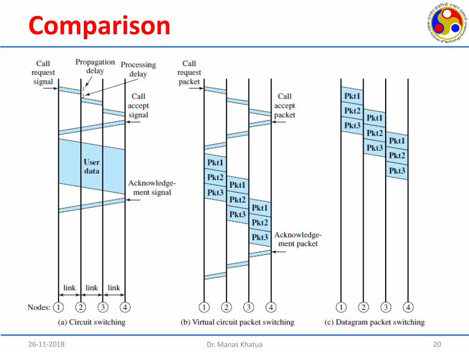
Comparison
26-11-2018 Dr. Manas Khatua 20
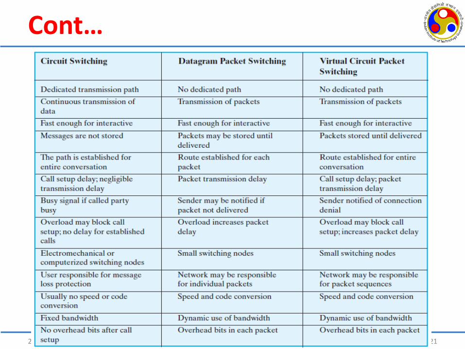
Cont…
26-11-2018 Dr. Manas Khatua 21
Which one is better?
• Ans.: None for all condition.
• For short message– Circuit switching might be faster
• For long message– Virtual Circuit switching might be faster
• w.r.t. average delay, flexibility, reliability– Datagram approach is better
26-11-2018 Dr. Manas Khatua 22
Interface Standard for PSN
26-11-2018 Dr. Manas Khatua 23
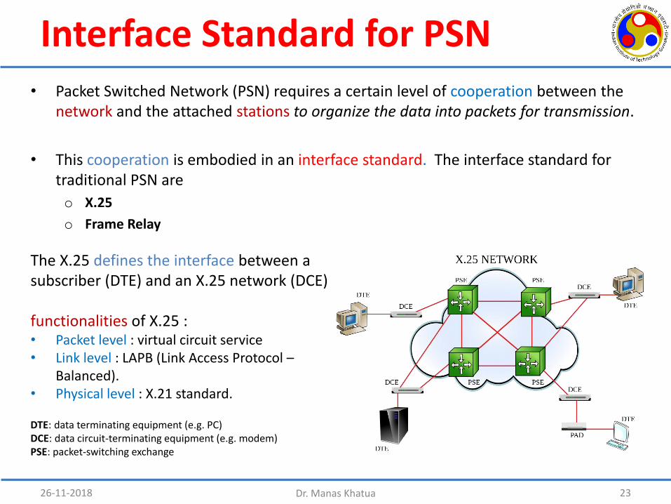
The X.25 defines the interface between a subscriber (DTE) and an X.25 network (DCE)
functionalities of X.25 :• Packet level : virtual circuit service• Link level : LAPB (Link Access Protocol –
Balanced). • Physical level : X.21 standard.
DTE: data terminating equipment (e.g. PC)DCE: data circuit-terminating equipment (e.g. modem)PSE: packet-switching exchange
• Packet Switched Network (PSN) requires a certain level of cooperation between the network and the attached stations to organize the data into packets for transmission.
• This cooperation is embodied in an interface standard. The interface standard for traditional PSN are
o X.25
o Frame Relay

X.25• packet level provides a virtual circuit
service which enables any subscriber to set up logical connections to other subscribers
• Exchanging control and user data packets
• link level provides for the reliable transfer of data across the physical link, by transmitting the data as a sequence of frames.
• Consists of the link access procedure for data interchange on the link between a DTE and a DCE
• physical level deals with the physical interface between an attached station (computer, terminal) and the link that attaches that station to the packet-switching node.
• Control the physical link between a DTE and a DCE.
26-11-2018 Dr. Manas Khatua 24
control information in X.25 packet • Virtual circuit number with which a packet
is associated• Send and Receive Sequence number
Cont…
• OSI Layers & X.25 Layers
– the OSI physical Layer corresponds to the X.25 physical layer
– the OSI data link layer to the X.25 link layer
– the OSI network layer to the X.25 packet layer
• Disadvantages of X.25
– at each intermediate node, state tables must be maintained for each virtual circuit in X.25 (for call control)
– At each hop the DLC protocol involves the exchange of data and ack frames (for error control/flow control)
26-11-2018 Dr. Manas Khatua 25

Frame Relay• Frame Relay offers higher
performance and greater transmission efficiency than X.25
• Frame Relay vs X.25– Call control signaling is carried on a
separate logical connection from user data. Thus, intermediate nodes need not maintain state tables
– There is no hop-by-hop flow control and error control.
– Multiplexing and switching of logical connections takes place at layer 2 instead of layer 3, eliminating one entire layer of processing.
– Frame Relay is a Layer 2 protocol suite, X.25 provides services at Layer 3
26-11-2018 Dr. Manas Khatua 26
• It is less expensive than leased lines and that is one reason for its popularity.
• It handles the transmission over a frequently changing path.

Asynchronous Transfer Mode (ATM)
• ATM is in some ways similar to packet switching using X.25 and frame relay.
• 1980’s effort by the phone companies to develop an integrated network standard (BISDN) that can support voice, data, video, etc
• ATM is a connection-oriented packet switching technology – that was designed to provide the performance of circuit-switching network and – the flexibility and efficiency of the packet-switching network
– uses small (53 Bytes) fixed size packets called “cells”
• Likewise packet switching using X.25 and frame relay, ATM allows multiple logical connections to be multiplexed over a single physical interface.
• Presently, wide acceptance of IP network reduces the role of ATM.– IP network is more scalable and less complex than ATM– IP supports data, voice and video traffic– Performance is very good
26-11-2018 Dr. Manas Khatua 27
26-11-2018 28Dr. Manas Khatua
Figure and slide materials are taken from the following sources:
1. W. Stallings, (2017), Data and Computer Communications, 10th Ed.2. NPTL lecture on Data Communication, by Prof. A. K. Pal, IIT Kharagpur3. B. A. Forouzan, (2012), Data Communication and Networking, 5th Ed.