CS25410 Memory Machine Code. Common types of non-rotating memory (1) RAMRandom Access Memory In...
48
CS25410 Memory Machine Code
-
Upload
jarrett-witcraft -
Category
Documents
-
view
219 -
download
0
Transcript of CS25410 Memory Machine Code. Common types of non-rotating memory (1) RAMRandom Access Memory In...

CS25410
Memory
Machine Code

Common types of non-rotating memory (1)
RAM Random Access MemoryIn reality, read/write memory
This is usually volatile, meaning it forgets its contents when the power is turned off
Magnetic core retains memory without power
ROM Read Only MemoryThis is non-volatile, and is written onto the
device permanently in the factory

Common types of memory (2)
PROM Programmable Read Only MemoryThis is non-volatile, and is written once by the
user. It cannot be written to a second time
EPROM Erasable PROMThis is a type of PROM that can be erased and
then re-programmed. Erasing is usually done by exposure to UV light

Common types of memory (3)
EEPROM Electrically Erasable PROMThis is another type of PROM that can be erased
and then re-programmed. This time, erasing can be done electronically in-circuit, by applying a high voltage
FLASH memoryAn improved EEPROM that is cheaper, faster and
has a higher density (so can store more)

Important Memory Attributes (1)
SizeThe total storage capacity, usually measured in
Megabits or Megabytes (increasingly, Gigabytes)
OrganisationThe number of locations, and the number of bits per location. The size in bits is the product of these two (e.g. 1M×32 = 32 Megabits, or 4 Megabytes in 1 million 32-bit words)

Important Memory Attributes (2)
SpeedHow quickly memory can respond to a read or
write command; often called access time, and quoted in nanoseconds (e.g. 70 ns memory)
Power consumptionHow much electricity it consumes, e.g. in
milliwatts per megabyte. This is important for battery-powered computers. Faster memory consumes more power

01101010010110101101010101101000101101010101010100010110101001011010110110110110101010011001010101011010101010101001010100100111010110110011010110101010010110101101010101101000101101010101010100010110101001011010110110110110101010011001010101011010101010101001010100100111010110110011010110111010100101101011010101011010001011010101010101000101101010010110101101101101101010100110010101010110101010101010010101001001110101101100110101101011010100101101011010101011010001011010101010101000101101010010110101101101101101010100110010101010110101010101010010101001001110101101100110101101011010100101101011010101011010001011010101010101000101101010010110101101101101101010100110010101010110101010101010010101001001110101101100110101101100110101100100101101101100100101101010101010100010010101010110101010101010010101001001110101101100110100101101010101010100010010101010110101010101010010101001001110101101001011010101010101000100101010101101010101010100101010010011101011011010011011001010
Machine Code
The commands the CPU understands

Machine Code
Definition: A set of binary codes that are recognised and executed directly by a particular CPU

Machine Instructions
• An individual machine code is called a Machine Instruction– e.g. the machine instruction to add 1 to the
value in accumulator A is 01001100 (or 4C if you prefer it in hex)
• The set of all codes recognised by a particular CPU is known as its Instruction Set

Machine Instructions
• A typical machine instruction consists of an operation code (op-code), which specifies what operation the CPU is to do, plus a number of arguments, which specify what data the CPU is to operate on– e.g. the machine instruction to add 2 to the
value in accumulator A is 10001011 00000010

What do/can machine instructions do?
We can group the instructions according to function. The groups given here are generally applicable to most instruction sets (i.e. they apply to the machine code for most types of processor)

Instructions: data transfer
• From where, to where?
• load (e.g. from memory to a register)
• store (e.g. from a register to memory)
• move (e.g. from register to register)
• …

Instructions: computations
• The arithmetic and logical operations, normally carried out by the ALU
• What might this include?
• add
• subtract
• increment
• invert bits … and more

Instructions: flow control
• A computer program is not a lot of use without loops, functions, etc.
• We need to have machine codes to control the flow of execution through a machine code program
• Branching, jumping to subroutines, returning from subroutines

Instructions: others
• You’ll come across other types of instruction as the course proceeds
• The bulk, however, fall into the three categories already mentioned:
• Data transfer
• Computations
• Flow control

The Programmer’s Model
• This is the way a programmer needs to view the CPU
• As a programmer, you don’t necessarily need to know about what we’ve learnt before regarding the internals but you need to know what’s sometimes termed the Programmer’s Model of the CPU

LC-3 Microcomputer
• Programmer’s Model

LC-3 Overview: Memory and Registers
• Memory– address space: 216 locations (16-bit addresses)– addressability: 16 bits

• Registers– temporary storage, accessed in a single machine
cycle• accessing memory generally takes longer than a
single cycle
– eight general-purpose registers: R0 - R7• each 16 bits wide
• how many bits to uniquely identify a register?
– other registers• not directly addressable, but used by (and affected
by) instructions
• PC (program counter), condition codes

LC-3 Overview: Instruction Set• Opcodes
– 15 opcodes– Operate instructions: ADD, AND, NOT– Data movement instructions: LD, LDI, LDR, LEA,
ST, STR, STI– Control instructions: BR, JSR/JSRR, JMP, RTI,
TRAP– some opcodes set/clear condition codes, based on
result:• N = negative, Z = zero, P = positive (> 0)

Instruction Set 2
• Data Types– 16-bit 2’s complement integer
• Addressing Modes– How is the location of an operand specified?– non-memory addresses: immediate, register– memory addresses: PC-relative, indirect,
base+offset

Operate Instructions
• Only three operations: ADD, AND, NOT
• Source and destination operands are registers– These instructions do not reference memory.– ADD and AND can use “immediate” mode,
where one operand is hard-wired into the instruction.

NOT (Register)
Note: Src and Dstcould be the same register.

ADD/AND registerthis zero means “register mode”
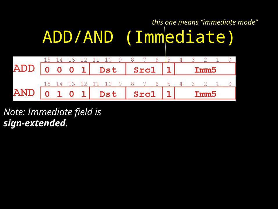
ADD/AND (Immediate)
Note: Immediate field issign-extended.
this one means “immediate mode”

Using Operate Instructions• With only ADD, AND, NOT…
– How do we subtract?
• Subtract: R3 = R1 - R2• Take 2’s complement of R2, then add to R1.• (1) R2 = NOT(R2)• (2) R2 = R2 + 1• (3) R3 = R1 + R2
– How do we OR?
• OR: R3 = R1 OR R2• Use DeMorgan’s Law -- invert R1 and R2, AND, then invert result.• (1) R1 = NOT(R1)• (2) R2 = NOT(R2)• (3) R3 = R1 AND R2• (4) R3 = NOT(R3)
– How do we copy from one register to another?
• Register-to-register copy: R3 = R2• R3 = R2 + 0 (Add-immediate)
– How do we initialize a register to zero?

Work aroundsHow do we OR?
• OR: R3 = R1 OR R2
• Use DeMorgan’s Law -- invert R1 and R2, AND, then invert result.
• (1) R1 = NOT(R1)
• (2) R2 = NOT(R2)
• (3) R3 = R1 AND R2
• (4) R3 = NOT(R3)
How do we copy from one register to another?
• Register-to-register copy: R3 = R2
• R3 = R2 + 0 (Add-immediate)

– How do we initialize a register to zero?• Initialize to zero: R1 = 0
• R1 = R1 AND 0 (And-immediate)

Data Movement Instructions•Load -- read data from memory to register
– LD: PC-relative mode– LDR: base+offset mode– LDI: indirect mode
•Store -- write data from register to memory– ST: PC-relative mode– STR: base+offset mode– STI: indirect mode
•Load effective address -- compute address, save in register
– LEA: immediate mode– does not access memory

PC-Relative Addressing Mode•Want to specify address directly in the instruction
– But an address is 16 bits, and so is an instruction!– After subtracting 4 bits for opcode
and 3 bits for register, we have 9 bits available for address.
•Solution:– Use the 9 bits as a signed offset from the current PC.
•9 bits:
•Can form any address X, such that: •Remember that PC is incremented as part of the FETCH phase;
•This is done before the EVALUATE ADDRESS stage.
255PCX256PC

LD (PC-Relative)
The instruction loads data from PC plus the offset on bits 0-8

ST (PC-Relative)
The instruction stores data from PC plus the offset on bits 0-8

Indirect Addressing Mode
•With PC-relative mode, can only address data within 256 words of the instruction.
– What about the rest of memory?
•Solution #1: – Read address from memory location,
then load/store to that address.•First address is generated from PC and IR(just like PC-relative addressing), thencontent of that address is used as target for load/store.

LDI (Indirect)
An address is formed as in the LD and ST forms. BUT the address pointed at contains the address of the operand.Therefore operand can be anywhere in memory.
Likewise for STI to store anywhere in memory

Base + Offset Addressing Mode
•With PC-relative mode, can only address data within 256 words of the instruction.
– What about the rest of memory?
•Solution #2:
– Use a register to generate a full 16-bit address.
•4 bits for opcode, 3 for src/dest register,3 bits for base register -- remaining 6 bits are usedas a signed offset.
– Offset is sign-extended before adding to base register.
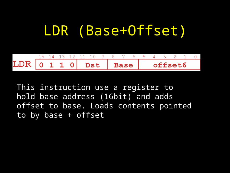
LDR (Base+Offset)
This instruction use a register to hold base address (16bit) and adds offset to base. Loads contents pointed to by base + offset

STR (Base+Offset)
This instruction use a register to hold base address (16bit) and adds offset to base. Stores contents of source in location pointed to by base + offset

Load Effective Address
•Computes address like PC-relative (PC plus signed offset) and stores the result into a register.
•Note: The address is stored in the register, not the contents of the memory location.

LEA (Immediate)
Destination will contain address of PC +1 +/- offset.

ExampleAddress Instruction Comments
x30F6 1 1 1 0 0 0 1 1 1 1 1 1 1 1 0 1 R1 PC – 3 = x30F4
x30F7 0 0 0 1 0 1 0 0 0 1 1 0 1 1 1 0 R2 R1 + 14 = x3102
x30F8 0 0 1 1 0 1 0 1 1 1 1 1 1 0 1 1 M[PC - 5] R2M[x30F4] x3102
x30F9 0 1 0 1 0 1 0 0 1 0 1 0 0 0 0 0 R2 0
x30FA 0 0 0 1 0 1 0 0 1 0 1 0 0 1 0 1 R2 R2 + 5 = 5
x30FB 0 1 1 1 0 1 0 0 0 1 0 0 1 1 1 0 M[R1+14] R2M[x3102] 5
x30FC 1 0 1 0 0 1 1 1 1 1 1 1 0 1 1 1R3 M[M[x30F4]]
R3 M[x3102]
R3 5
opcode

Control Instructions• Used to alter the sequence of instructions
(by changing the Program Counter)• Conditional Branch
– branch is taken if a specified condition is true• signed offset is added to PC to yield new PC
– else, the branch is not taken• PC is not changed, points to the next sequential instruction
• Unconditional Branch (or Jump)– always changes the PC
• TRAP– changes PC to the address of an OS “service routine”– routine will return control to the next instruction (after TRAP)

Condition Codes
• LC-3 has three condition code registers:N -- negativeZ -- zeroP -- positive (greater than zero)
• Set by any instruction that writes a value to a register(ADD, AND, NOT, LD, LDR, LDI, LEA)
• Exactly one will be set at all times– Based on the last instruction that altered a
register

Branch Instruction
• Branch specifies one or more condition codes.
• If the set bit is specified, the branch is taken.
– PC-relative addressing:target address is made by adding signed offset (IR[8:0])to current PC.
– Note: PC has already been incremented by FETCH stage.
– Note: Target must be within 256 words of BR instruction.
• If the branch is not taken,
the next sequential instruction is executed.

BR (PC-Relative)
What happens if bits [11:9] are all zero? All one?

Using Branch Instructions• Compute sum of 12 integers. (Numbers start at
location x3100. Program starts at location x3000
•.
R1 x3100R3 0R2 12
R2=0?
R4 M[R1]R3 R3+R4R1 R1+1R2 R2-1
NO
YES

Sample ProgramAddress Instruction Comments
x3000 1 1 1 0 0 0 1 0 1 1 1 1 1 1 1 1 R1 x3100 (PC+0xFF)
x3001 0 1 0 1 0 1 1 0 1 1 1 0 0 0 0 0 R3 0
x3002 0 1 0 1 0 1 0 0 1 0 1 0 0 0 0 0 R2 0
x3003 0 0 0 1 0 1 0 0 1 0 1 0 1 1 0 0 R2 12
x3004 0 0 0 0 0 1 0 0 0 0 0 0 0 1 0 1 If Z, goto x300A (PC+5)
x3005 0 1 1 0 1 0 0 0 0 1 0 0 0 0 0 0 Load next value to R4
x3006 0 0 0 1 0 1 1 0 1 1 0 0 0 0 0 1 Add to R3
x3007 0 0 0 1 0 0 1 0 0 1 1 0 0 0 0 1 Increment R1 (pointer)
X3008 0 0 0 1 0 1 0 0 1 0 1 1 1 1 1 1 Decrement R2 (counter)
x3009 0 0 0 0 1 1 1 1 1 1 1 1 1 0 1 0 Goto x3004 (PC-6)

JMP (Register)• Jump is an unconditional branch -- always taken.
– Target address is the contents of a register.– Allows any target address.

TRAP
• Calls a service routine, identified by 8-bit “trap vector.”
• When routine is done, PC is set to the instruction following TRAP.
vector routine
x23 input a character from the keyboard
x21 output a character to the monitor
x25 halt the program