CS230 Instruction Manual - Campbell Sci · 2017-06-06 · precautions . danger — many hazards are...
31
INSTRUCTION MANUAL CS230 Temperature Profiler Revision: 4/17 Copyright © 2016-2017 Campbell Scientific, Inc.
Transcript of CS230 Instruction Manual - Campbell Sci · 2017-06-06 · precautions . danger — many hazards are...
INST
RU
CT
ION
MA
NU
AL
CS230 Temperature Profiler Revision: 4/17
C o p y r i g h t © 2 0 1 6 - 2 0 1 7 C a m p b e l l S c i e n t i f i c , I n c .

Assistance
Products may not be returned without prior authorization. The following
contact information is for Canadian and international clients residing in
countries served by Campbell Scientific (Canada) Corp. directly. Affiliate
companies handle repairs for clients within their territories. Please visit
www.campbellsci.ca to determine which Campbell Scientific company serves
your country.
To obtain a Returned Materials Authorization (RMA), contact CAMPBELL
SCIENTIFIC (CANADA) CORP., phone (780) 454-2505. After a
measurement consultant determines the nature of the problem, an RMA
number will be issued. Please write this number clearly on the outside of the
shipping container. Campbell Scientific’s shipping address is:
CAMPBELL SCIENTIFIC (CANADA) CORP. RMA#_____
14532 131 Avenue NW
Edmonton, Alberta T5L 4X4
Canada
For all returns, the client must fill out a “Statement of Product Cleanliness and
Decontamination” form and comply with the requirements specified in it. The
form is available from our web site at www.campbellsci.ca/repair. A
completed form must be either emailed to [email protected] or faxed to
(780) 454-2655. Campbell Scientific (Canada) Corp. is unable to process any
returns until we receive this form. If the form is not received within three days
of product receipt or is incomplete, the product will be returned to the client at
the client’s expense. Campbell Scientific (Canada) Corp.f reserves the right to
refuse service on products that were exposed to contaminants that may cause
health or safety concerns for our employees.
Precautions DANGER — MANY HAZARDS ARE ASSOCIATED WITH INSTALLING, USING, MAINTAINING, AND WORKING ON OR AROUND
TRIPODS, TOWERS, AND ANY ATTACHMENTS TO TRIPODS AND TOWERS SUCH AS SENSORS, CROSSARMS, ENCLOSURES,
ANTENNAS, ETC. FAILURE TO PROPERLY AND COMPLETELY ASSEMBLE, INSTALL, OPERATE, USE, AND MAINTAIN TRIPODS,
TOWERS, AND ATTACHMENTS, AND FAILURE TO HEED WARNINGS, INCREASES THE RISK OF DEATH, ACCIDENT, SERIOUS
INJURY, PROPERTY DAMAGE, AND PRODUCT FAILURE. TAKE ALL REASONABLE PRECAUTIONS TO AVOID THESE HAZARDS.
CHECK WITH YOUR ORGANIZATION'S SAFETY COORDINATOR (OR POLICY) FOR PROCEDURES AND REQUIRED PROTECTIVE EQUIPMENT PRIOR TO PERFORMING ANY WORK.
Use tripods, towers, and attachments to tripods and towers only for purposes for which they are designed. Do not exceed design
limits. Be familiar and comply with all instructions provided in product manuals. Manuals are available at www.campbellsci.ca or by
telephoning (780) 454-2505 (Canada). You are responsible for conformance with governing codes and regulations, including safety
regulations, and the integrity and location of structures or land to which towers, tripods, and any attachments are attached. Installation
sites should be evaluated and approved by a qualified personnel (e.g. engineer). If questions or concerns arise regarding installation,
use, or maintenance of tripods, towers, attachments, or electrical connections, consult with a licensed and qualified engineer or
electrician.
General
Prior to performing site or installation work, obtain required approvals and permits.
Use only qualified personnel for installation, use, and maintenance of tripods and towers, and
any attachments to tripods and towers. The use of licensed and qualified contractors is
highly recommended.
Read all applicable instructions carefully and understand procedures thoroughly before
beginning work.
Wear a hardhat and eye protection, and take other appropriate safety precautions while
working on or around tripods and towers.
Do not climb tripods or towers at any time, and prohibit climbing by other persons. Take
reasonable precautions to secure tripod and tower sites from trespassers.
Use only manufacturer recommended parts, materials, and tools.
Utility and Electrical
You can be killed or sustain serious bodily injury if the tripod, tower, or attachments you are
installing, constructing, using, or maintaining, or a tool, stake, or anchor, come in contact
with overhead or underground utility lines.
Maintain a distance of at least one-and-one-half times structure height, 6 meters (20 feet), or
the distance required by applicable law, whichever is greater, between overhead utility lines
and the structure (tripod, tower, attachments, or tools).
Prior to performing site or installation work, inform all utility companies and have all
underground utilities marked.
Comply with all electrical codes. Electrical equipment and related grounding devices should
be installed by a licensed and qualified electrician.
Elevated Work and Weather
Exercise extreme caution when performing elevated work.
Use appropriate equipment and safety practices.
During installation and maintenance, keep tower and tripod sites clear of un-trained or non-
essential personnel. Take precautions to prevent elevated tools and objects from dropping.
Do not perform any work in inclement weather, including wind, rain, snow, lightning, etc.
Maintenance
Periodically (at least yearly) check for wear and damage, including corrosion, stress cracks,
frayed cables, loose cable clamps, cable tightness, etc. and take necessary corrective actions.
Periodically (at least yearly) check electrical ground connections.
WHILE EVERY ATTEMPT IS MADE TO EMBODY THE HIGHEST DEGREE OF SAFETY IN ALL CAMPBELL SCIENTIFIC PRODUCTS,
THE CLIENT ASSUMES ALL RISK FROM ANY INJURY RESULTING FROM IMPROPER INSTALLATION, USE, OR MAINTENANCE OF
TRIPODS, TOWERS, OR ATTACHMENTS TO TRIPODS AND TOWERS SUCH AS SENSORS, CROSSARMS, ENCLOSURES, ANTENNAS,
ETC.
PLEASE READ FIRST About this manual Please note that this manual was originally produced by Campbell Scientific Inc. (CSI) primarily for the US market. Some spellings, weights and measures may reflect this origin. Some useful conversion factors:
Area: 1 in2 (square inch) = 645 mm2
Length: 1 in. (inch) = 25.4 mm 1 ft (foot) = 304.8 mm 1 yard = 0.914 m 1 mile = 1.609 km Mass: 1 oz. (ounce) = 28.35 g 1 lb (pound weight) = 0.454 kg Pressure: 1 psi (lb/in2) = 68.95 mb Volume: 1 US gallon = 3.785 litres
In addition, part ordering numbers may vary. For example, the CABLE5CBL is a CSI part number and known as a FIN5COND at Campbell Scientific Canada (CSC). CSC Technical Support will be pleased to assist with any questions.
About sensor wiring Please note that certain sensor configurations may require a user supplied jumper wire. It is recommended to review the sensor configuration requirements for your application and supply the jumper wire is necessary.

i
Table of Contents PDF viewers: These page numbers refer to the printed version of this document. Use the PDF reader bookmarks tab for links to specific sections.
1. Introduction ................................................................ 1
2. Precautions ................................................................ 1
3. Initial Inspection ......................................................... 1
4. Overview ..................................................................... 1
5. Specifications ............................................................. 2
5.1 SGB3 3-Line Surge Protector .............................................................. 2 5.2 CS230 Temperature Profiler ................................................................ 2
6. Installation .................................................................. 3
6.1 Siting .................................................................................................... 3 6.2 Mounting .............................................................................................. 5
7. Operation .................................................................... 5
7.1 Wiring .................................................................................................. 6 7.1.1 Long Cables .................................................................................. 7 7.1.2 Power Conservation ...................................................................... 7
7.2 Reading the CS230............................................................................... 7 7.2.1 SDI-12 Addressing ....................................................................... 9 7.2.2 Slow Sequence Program Instructions ......................................... 10
7.2.2.1 CR1000 Program to Read the Meta Data of 15 Sensors Daily ............................................................................. 11
7.2.3 CS230 Metadata .......................................................................... 12 7.2.3.1 CR1000 Program to Read the Meta Data of 15 Sensors
Daily ............................................................................. 13 7.2.4 Example Programs ...................................................................... 14
7.2.4.1 CR1000 Program for Measuring 15 Sensors Every 60 Seconds ......................................................................... 14
7.2.4.2 CR1000 Program for Measuring 15 Sensors Every 5 Minutes ......................................................................... 15
7.3 Changing the SDI-12 Address Using LoggerNet and a Datalogger ... 17 7.3.1 CR1000 and CR800 Series Dataloggers ..................................... 17
8. Maintenance and Calibration .................................. 18
9. Troubleshooting ....................................................... 18
Figures 6-1. CS230 Installation Example ................................................................. 4
Table of Contents
ii
6-2. Internal Sensor Label........................................................................... 5 7-1. SGB3 3-Line Surge Protector .............................................................. 6 7-2. Screen capture of SDI-12 transparent mode on CRBasic CR800
datalogger using control port 1 and prompting for SDI-12 addresses ........................................................................................ 18
Tables 7-1. CS230 Connection to SGB3 ................................................................ 6 7-2. SGB3 Connection to Campbell Scientific Dataloggers ....................... 6 7-3. SDI-12 Commands for the CS230 ....................................................... 9 7-4. SDI-12 Addresses and Positions ....................................................... 10 7-5. Meta Data Details .............................................................................. 12
1
CS230 Temperature Profiler 1. Introduction
The CS230 temperature profiler provides temperature measurements both in a rigid probe assembly and external probes using digital sensor technology. It uses the SDI-12 communication protocols to communicate with an SDI-12 recorder simplifying installation and programming. The included SGB3 provides electrical surge protection.
Before using the CS230 please study:
• Section 2, Precautions (p. 1) • Section 7.1, Wiring (p. 6)
More details are available in the remaining sections.
2. Precautions • Although the CS230 is designed to be a rugged and reliable device for
field use, care should be taken when handling or moving it to avoid damage.
• There are no user-serviceable parts and any attempt to disassemble the device will void the warranty.
• The CS230 must be used in conjunction with the SGB3 to protect against electrical surges.
3. Initial Inspection • Upon receipt of the CS230, inspect the packaging and contents for
damage. File any damage claims with the shipping company. Immediately check package contents against the shipping documentation. Contact Campbell Scientific about any discrepancies.
• The model number and cable length are printed on a label at the connection end of the cable. Check this information against the shipping documents to ensure the expected product and cable length are received.
• The CS230 ships with a SGB3 surge protector, a 2-ft cable, 2 pan Phillips screws, and 2 grommets.
4. Overview The CS230 temperature profiler makes use of digital sensor technology allowing for a simple 3-wire integration. The CS230 consists of a rigid probe assembly and up to 4 optional external temperature probes. The rigid probe assembly maintains the precise position of the temperature points within the profile, while protecting the temperature sensors in all mediums.
CS230 Temperature Profiler
2
The CS230 is suited for a wide variety of applications and environments. The completely sealed probe assembly and external probes permits the CS230 to be used in roadbeds, soils, and water (snow and ice).
Examples of some applications include spring load adjustment, frost and permafrost monitoring, soil and water temperature profiling, and snowpack temperature profiling.
The purpose of the SGB3 is to provide adequate surge protection for the CS230 Temperature Profiler. The case of the SGB3 is suited for mounting to a back plate with 1 inch on center spacing.
5. Specifications Features:
• Accurate and stable measurements • Each sensor is individually addressed and referenced to its depth • Low power consumption • Digital SDI-12 output • Compatible with the following dataloggers: CR200(X) Series, CR800
Series, CR1000, CR3000, CR5000, CR510, CR10(X), CR23X
5.1 SGB3 3-Line Surge Protector Operating Range: –55 to 85 °C
Maximum Voltage: ±28 Vdc / 20Vac (L1, L2, L3 with respect to G terminals)
Maximum Current: 2 A per terminal, 4 A total (requires both ground terminals for return current)
Maximum Rated Surge: 1200 Amps (8/20 us)
5.2 CS230 Temperature Profiler Operating Range: –55 to 85 °C
Accuracy
Typical: ±0.2 °C over –40 to 85 °C,
Worst Case: ±0.4 °C over –40 to 85 °C; ±0.5 °C over –55 to –40 °C
(includes lifetime drift of sensor)
Resolution: 0.0078 °C
Measurement Update Interval: 1 s (automatic), occurs in quiescent mode
Warm-up Time: 10 seconds
CS230 Temperature Profiler
3
Time Constant (Ice Bath) External Probe: 60 s Tee Sensor: 720 s Second Sensor from Tee: 420 s Remainder of Profiler: 300 s
Maximum Sensors per Probe: 32 sensors, in rigid probe assembly
External Probe: Maximum of 4 of these optional probes
External Probe Length: 45 cm (18 in)
Supply Voltage: 9 to 28 Vdc
Current Consumption
Quiescent: # sensors • 1.0 mA (max)
Active (during SDI-12 communications): 20 mA + (# sensors • 1.0 mA)
Probe Diameter: 2.13 cm (0.84 in)
Maximum Length: 3.0 m (118 in)
Maximum Cable Length: 152 m (500 ft), individual CS230 and datalogger SDI-12 terminal maximum
Minimum Sensor Spacing: 5cm (1.97 in) in rigid probe assembly
View compliance documentation at www.campbellsci.com/cs230-l.
The black outer jacket of the cable is Santoprene® rubber. This compound was chosen for its resistance to temperature extremes, moisture, and UV degradation. However, this jacket will support combustion in air. It is rated as slow burning when tested according to U.L. 94 H.B. and will pass FMVSS302. Local fire codes may preclude its use inside buildings.
6. Installation 6.1 Siting
The CS230 is meant to be installed within the medium that is to be monitored. The types of medium that can be measured are varied, including soils, roadbeds, and water. To make the most representative measurement it is important that consistent contact be made between the temperature profiler and the medium.
The location of the temperature profiler should be representative of the intended application. Typically the first measurement point in the CS230 rigid assembly should have a minimum burial depth of 20 cm. This helps protect the sensor from damage in roadbed applications, and helps secure the sensor against frost heaving. Use the external probes for measurements at shallower
NOTE
CS230 Temperature Profiler
4
depths. The external probes are sheathed in a stainless-steel housing to protect them against possible damage.
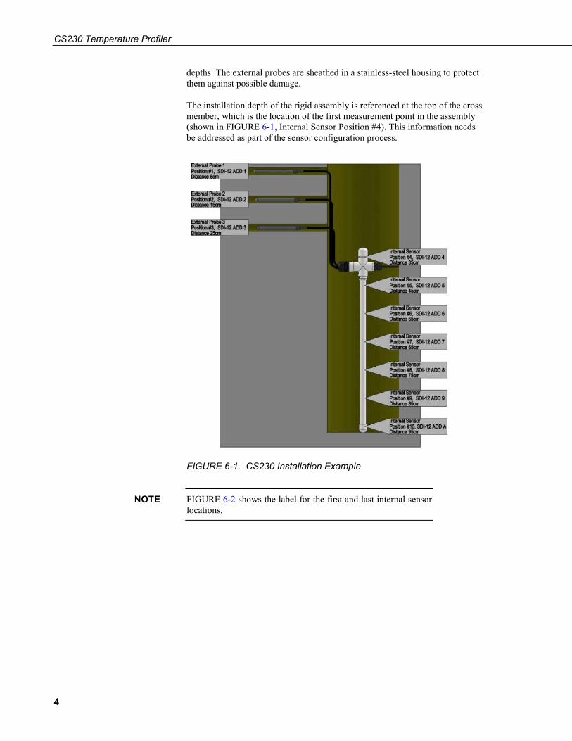
The installation depth of the rigid assembly is referenced at the top of the cross member, which is the location of the first measurement point in the assembly (shown in FIGURE 6-1, Internal Sensor Position #4). This information needs be addressed as part of the sensor configuration process.
FIGURE 6-1. CS230 Installation Example
FIGURE 6-2 shows the label for the first and last internal sensor locations.
NOTE

CS230 Temperature Profiler
5
FIGURE 6-2. Internal Sensor Label
6.2 Mounting Orient and secure the CS230 in the measurement medium. Keep materials removed during installation and use that material as backfill.
While installing the CS230, the depth must be referenced between the surface of the medium and the top of the cross member of the CS230 (shown in FIGURE 6-1, Internal Sensor Position #4). If the rigid assembly is not placed at the correct depth, all measurement depths will be out of place.
Install the external probes horizontally in the measurement medium. This helps ensure that the most representative measurement is taken at the given depth, and will not interfere with other nearby measurements.
Orient the signal and power cable of the CS230 towards the datalogger to avoid loops or strain on the cable. Also use a suitable trench or conduit to protect the signal and power cable from damage.
Mount the SGB3 inside the datalogger enclosure. Use the supplied hardware to secure it to the enclosure backplate.
7. Operation When power is supplied to the CS230 probe, the internal electronics continuously measures the temperature approximately once per second. The sensor outputs a running average of 10 consecutive, 1 second readings. The accuracy specification is based on an average of 10 consecutive readings. Therefore, after initial power up, a delay of 10 s is recommended to obtain the best accuracy.
Outputs of both lifetime and user resettable minimum and maximum temperatures are also available during powered operation from each temperature point in the CS230. The user resettable minimum and maximum
CS230 Temperature Profiler
6
temperatures can be used to monitor specific seasons or periods of measure, without having to review the entire data set. The lifetime minimum and maximum temperatures are used for maintenance and warranty records.
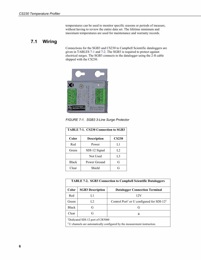
7.1 Wiring Connections for the SGB3 and CS230 to Campbell Scientific dataloggers are given in TABLES 7-1 and 7-2. The SGB3 is required to protect against electrical surges. The SGB3 connects to the datalogger using the 2-ft cable shipped with the CS230.
FIGURE 7-1. SGB3 3-Line Surge Protector
TABLE 7-1. CS230 Connection to SGB3
Color Description CS230
Red Power L1
Green SDI-12 Signal L2
Not Used L3
Black Power Ground G
Clear Shield G
TABLE 7-2. SGB3 Connection to Campbell Scientific Dataloggers
Color SGB3 Description Datalogger Connection Terminal
Red L1 12V
Green L2 Control Port1 or U configured for SDI-122
Black G G
Clear G ⏚ 1Dedicated SDI-12 port of CR5000 2 U channels are automatically configured by the measurement instruction.
CS230 Temperature Profiler
7
To use more than one probe per datalogger, either connect the different probes to different SDI-12 compatible ports on the datalogger or change the SDI-12 addresses of the probes and let them share the same connection. Using the SDI-12 addressing method minimizes the use of ports on the datalogger (see below for limits on the total cable length).
There are two ways to set the SDI-12 address of the CS230:
• By sending the required commands to the sensors via an SDI-12 recorder/datalogger that allows talk through to the sensor
• By loading a program into the datalogger that sends the required commands (see Section 7.3, Changing the SDI-12 Address Using LoggerNet and a Datalogger (p. 17))
7.1.1 Long Cables As the measurement data is transferred between the temperature profiler and datalogger digitally, there are no offset errors incurred with increasing cable length as seen with analog sensors. However, with long enough cable lengths, the digital communications will break down, resulting in either no response from the sensor or corrupted readings. The original SDI-12 standard specifies the maximum total cable length for the cable as being 61 m (200 ft), but we are able to exceed this limit by:
• Using low capacitance, low resistance, screened cable
• Ensuring that the power ground cable has low resistance and is connected to the same ground reference as the datalogger control ports
7.1.2 Power Conservation The CS230 draws less than 1 mA of current per sensor between polling sessions from its 12 V supply. In many applications this is minimal compared to overall system power use, so the sensor can be permanently powered to avoid the warm up period.
In very low power applications, you can switch the power on a minimum of 10 s (allowing for the warm-up period) before polling the CS230. This switching can be achieved in different ways depending on the type and model of your datalogger. If available, the switched 12 V output of the datalogger can be used.
7.2 Reading the CS230 When power is supplied to the CS230, the internal electronics continuously measure temperature at a rate of approximately once per second. Every output measurement (aR0! or aM0!) obtained from the sensor is a running average of 10 consecutive readings. For this purpose after initial power up, a delay of 10 s is recommended to obtain the best accuracy.
As the sensor is obtaining a measurement every second, Campbell Scientific recommends using the continuous measurement command (aR0!) to obtain the temperature readings. Using the aR0! commands reduces the time taken in comparison to the aM0! to obtain a reading via the SDI-12 protocol. The
CS230 Temperature Profiler
8
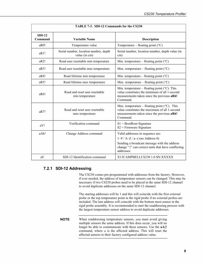
lifetime and user resettable minimum and maximum temperature values are single 1 second readings. For more details, see TABLE 7-3.
The CS230 complies with a subset of the SDI-12 1.3 instruction set. Specifically, it supports these SDI-12 commands:
• a! acknowledge active of individual sensor
• aI!, send identification
• aR! (aR0! to aR7!), continuous measurements of the sensor. The R command provides a faster means of obtaining the readings for sensors that can provide continuous measurements. This instruction usually takes less than 300 milliseconds to execute.
• aM!, initiate measurement (and the subsequent aD0! “get data” command which is automatically sent by a Campbell Scientific datalogger). This instruction usually takes about 700 milliseconds to execute.
• aAb!, change address a to b
Where in all cases “a” is the address of the sensor and “!” is the command terminator. These two characters are normally sent implicitly by Campbell Scientific dataloggers.
The CS230 output is measured using a standard SDI-12 instruction to read the data from an SDI-12 sensor. For CRBasic dataloggers, the SDI12Recorder() instruction is used. For Campbell Scientific Edlog dataloggers, Instruction 105 is used. If using the sensor with other SDI-12 recorders, please refer to your system’s documentation.
In any configuration of CS230 that includes more than one sensor, the CS230 will not respond to the ?! SDI-12 command as each individual sensor will respond at the same time thus disrupting all outputs. Use the aI! command in a trial and error fashion if you need to determine the individual addresses of temperature sensors.
NOTE
CS230 Temperature Profiler
9
TABLE 7-3. SDI-12 Commands for the CS230
SDI-12 Command Variable Name Description
aR0! Temperature value Temperature – floating point (°C)
aR1! Serial number, location number, depth value (in cm)
Serial number, location number, depth value (in cm)
aR2! Read user resettable min temperature Min. temperature – floating point (°C)
aR3! Read user resettable max temperature Max. temperature – floating point (°C)
aR4! Read lifetime min temperature Min. temperature – floating point (°C)
aR5! Read lifetime max temperature Max. temperature – floating point (°C)
aR6! Read and reset user resettable min temperature
Min. temperature – floating point (°C). This value constitutes the minimum of all 1-second measurements taken since the previous aR6! Command.
aR7! Read and reset user resettable max temperature
Max. temperature – floating point (°C). This value constitutes the maximum of all 1-second measurements taken since the previous aR6! Command.
aV! Verification command S1 = BootRom Signature S2 = Firmware Signature
aAb! Change Address command Valid addresses in sequence are: 1–9 / A–Z / a–z (no Address 0) Sending a broadcast message with the address change “{” can correct units that have conflicting addresses.
aI! SDI-12 Identification command X13CAMPBELLCS230 1.0 SN:XXXXX
7.2.1 SDI-12 Addressing The CS230 comes pre-programmed with addresses from the factory. However, if ever needed, the address of temperature sensors can be changed. This may be necessary if two CS230 probes need to be placed in the same SDI-12 channel to avoid duplicate addresses on the same SDI-12 channel.
The starting addresses will be 1 and this will coincide with the first external probe or the top temperature point in the rigid probe if no external probes are included. The last address will coincide with the bottom most sensor in the rigid probe assembly. It is recommended to start the readdressing process with the largest temperature sensor address to avoid duplicate addresses.
When readdressing temperature sensors, you must avoid giving multiple sensors the same address. If this does occur, you will no longer be able to communicate with these sensors. Use the aA{! command, where a is the affected address. This will reset the affected sensors to their factory configured address value.
NOTE
CS230 Temperature Profiler
10
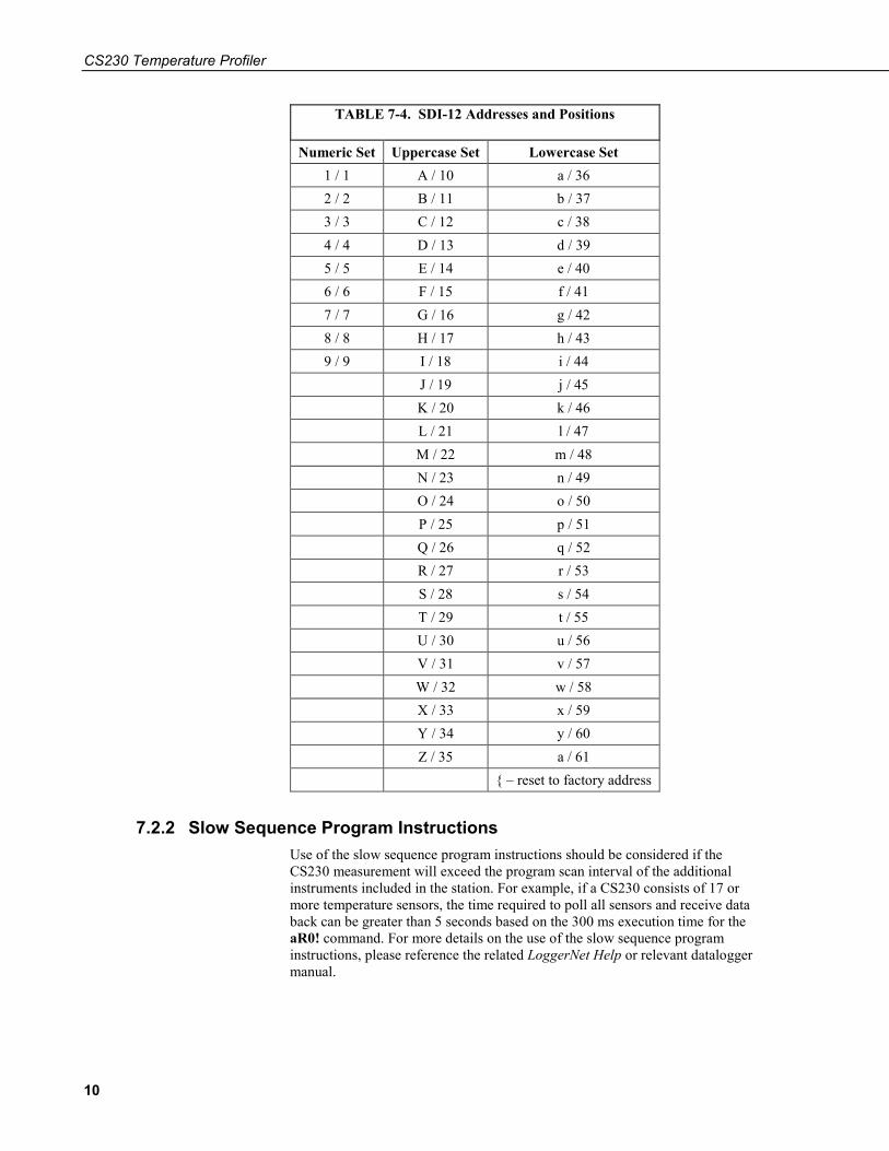
TABLE 7-4. SDI-12 Addresses and Positions
Numeric Set Uppercase Set Lowercase Set 1 / 1 A / 10 a / 36 2 / 2 B / 11 b / 37 3 / 3 C / 12 c / 38 4 / 4 D / 13 d / 39 5 / 5 E / 14 e / 40 6 / 6 F / 15 f / 41 7 / 7 G / 16 g / 42 8 / 8 H / 17 h / 43 9 / 9 I / 18 i / 44
J / 19 j / 45 K / 20 k / 46 L / 21 l / 47 M / 22 m / 48 N / 23 n / 49 O / 24 o / 50 P / 25 p / 51 Q / 26 q / 52 R / 27 r / 53 S / 28 s / 54 T / 29 t / 55 U / 30 u / 56 V / 31 v / 57 W / 32 w / 58 X / 33 x / 59 Y / 34 y / 60 Z / 35 a / 61 { – reset to factory address
7.2.2 Slow Sequence Program Instructions Use of the slow sequence program instructions should be considered if the CS230 measurement will exceed the program scan interval of the additional instruments included in the station. For example, if a CS230 consists of 17 or more temperature sensors, the time required to poll all sensors and receive data back can be greater than 5 seconds based on the 300 ms execution time for the aR0! command. For more details on the use of the slow sequence program instructions, please reference the related LoggerNet Help or relevant datalogger manual.
CS230 Temperature Profiler
11
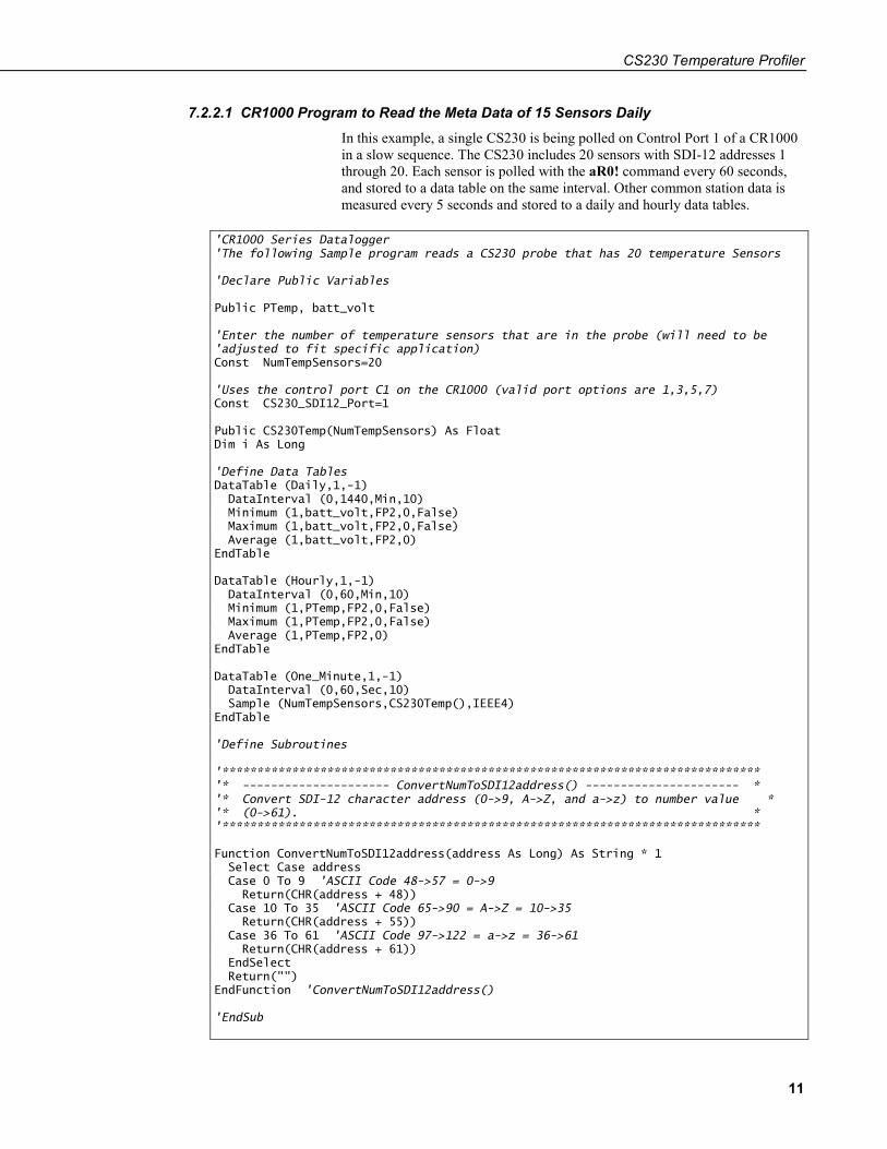
7.2.2.1 CR1000 Program to Read the Meta Data of 15 Sensors Daily In this example, a single CS230 is being polled on Control Port 1 of a CR1000 in a slow sequence. The CS230 includes 20 sensors with SDI-12 addresses 1 through 20. Each sensor is polled with the aR0! command every 60 seconds, and stored to a data table on the same interval. Other common station data is measured every 5 seconds and stored to a daily and hourly data tables.
'CR1000 Series Datalogger 'The following Sample program reads a CS230 probe that has 20 temperature Sensors 'Declare Public Variables Public PTemp, batt_volt 'Enter the number of temperature sensors that are in the probe (will need to be 'adjusted to fit specific application) Const NumTempSensors=20 'Uses the control port C1 on the CR1000 (valid port options are 1,3,5,7) Const CS230_SDI12_Port=1 Public CS230Temp(NumTempSensors) As Float Dim i As Long 'Define Data Tables DataTable (Daily,1,-1) DataInterval (0,1440,Min,10) Minimum (1,batt_volt,FP2,0,False) Maximum (1,batt_volt,FP2,0,False) Average (1,batt_volt,FP2,0) EndTable DataTable (Hourly,1,-1) DataInterval (0,60,Min,10) Minimum (1,PTemp,FP2,0,False) Maximum (1,PTemp,FP2,0,False) Average (1,PTemp,FP2,0) EndTable DataTable (One_Minute,1,-1) DataInterval (0,60,Sec,10) Sample (NumTempSensors,CS230Temp(),IEEE4) EndTable 'Define Subroutines '***************************************************************************** '* --------------------- ConvertNumToSDI12address() ---------------------- * '* Convert SDI-12 character address (0->9, A->Z, and a->z) to number value * '* (0->61). * '***************************************************************************** Function ConvertNumToSDI12address(address As Long) As String * 1 Select Case address Case 0 To 9 'ASCII Code 48->57 = 0->9 Return(CHR(address + 48)) Case 10 To 35 'ASCII Code 65->90 = A->Z = 10->35 Return(CHR(address + 55)) Case 36 To 61 'ASCII Code 97->122 = a->z = 36->61 Return(CHR(address + 61)) EndSelect Return("") EndFunction 'ConvertNumToSDI12address() 'EndSub
CS230 Temperature Profiler
12
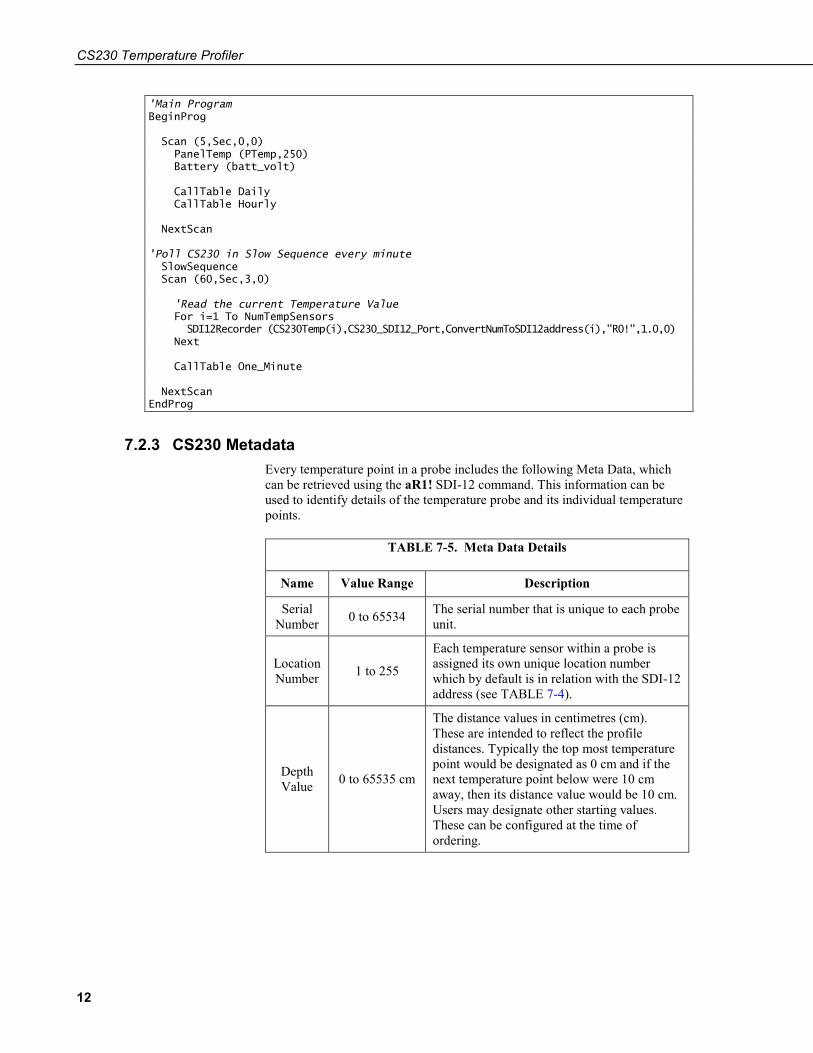
'Main Program BeginProg Scan (5,Sec,0,0) PanelTemp (PTemp,250) Battery (batt_volt) CallTable Daily CallTable Hourly NextScan 'Poll CS230 in Slow Sequence every minute SlowSequence Scan (60,Sec,3,0) 'Read the current Temperature Value For i=1 To NumTempSensors SDI12Recorder (CS230Temp(i),CS230_SDI12_Port,ConvertNumToSDI12address(i),"R0!",1.0,0) Next CallTable One_Minute NextScan EndProg
7.2.3 CS230 Metadata Every temperature point in a probe includes the following Meta Data, which can be retrieved using the aR1! SDI-12 command. This information can be used to identify details of the temperature probe and its individual temperature points.
TABLE 7-5. Meta Data Details
Name Value Range Description
Serial Number 0 to 65534 The serial number that is unique to each probe
unit.
Location Number 1 to 255
Each temperature sensor within a probe is assigned its own unique location number which by default is in relation with the SDI-12 address (see TABLE 7-4).
Depth Value 0 to 65535 cm
The distance values in centimetres (cm). These are intended to reflect the profile distances. Typically the top most temperature point would be designated as 0 cm and if the next temperature point below were 10 cm away, then its distance value would be 10 cm. Users may designate other starting values. These can be configured at the time of ordering.
CS230 Temperature Profiler
13
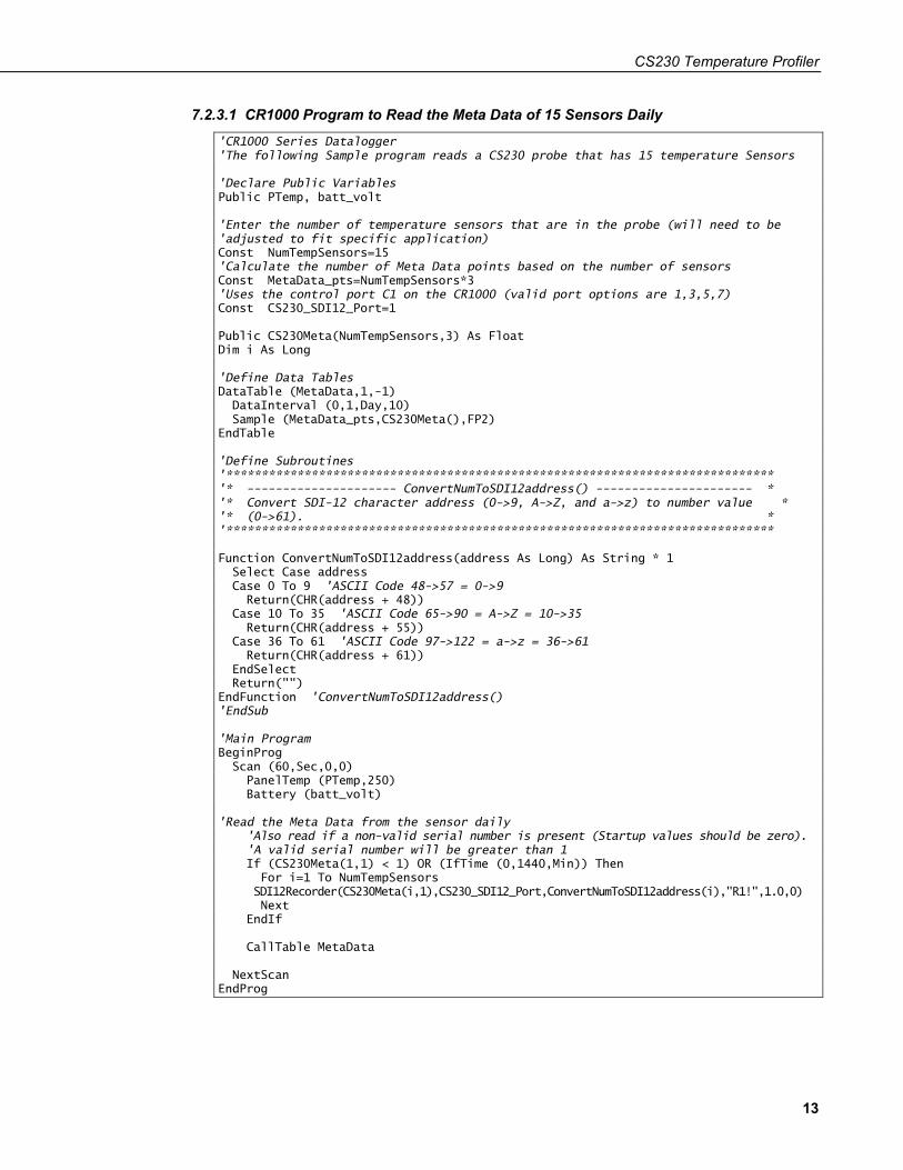
7.2.3.1 CR1000 Program to Read the Meta Data of 15 Sensors Daily
'CR1000 Series Datalogger 'The following Sample program reads a CS230 probe that has 15 temperature Sensors 'Declare Public Variables Public PTemp, batt_volt 'Enter the number of temperature sensors that are in the probe (will need to be 'adjusted to fit specific application) Const NumTempSensors=15 'Calculate the number of Meta Data points based on the number of sensors Const MetaData_pts=NumTempSensors*3 'Uses the control port C1 on the CR1000 (valid port options are 1,3,5,7) Const CS230_SDI12_Port=1 Public CS230Meta(NumTempSensors,3) As Float Dim i As Long 'Define Data Tables DataTable (MetaData,1,-1) DataInterval (0,1,Day,10) Sample (MetaData_pts,CS230Meta(),FP2) EndTable 'Define Subroutines '***************************************************************************** '* --------------------- ConvertNumToSDI12address() ---------------------- * '* Convert SDI-12 character address (0->9, A->Z, and a->z) to number value * '* (0->61). * '***************************************************************************** Function ConvertNumToSDI12address(address As Long) As String * 1 Select Case address Case 0 To 9 'ASCII Code 48->57 = 0->9 Return(CHR(address + 48)) Case 10 To 35 'ASCII Code 65->90 = A->Z = 10->35 Return(CHR(address + 55)) Case 36 To 61 'ASCII Code 97->122 = a->z = 36->61 Return(CHR(address + 61)) EndSelect Return("") EndFunction 'ConvertNumToSDI12address() 'EndSub 'Main Program BeginProg Scan (60,Sec,0,0) PanelTemp (PTemp,250) Battery (batt_volt) 'Read the Meta Data from the sensor daily 'Also read if a non-valid serial number is present (Startup values should be zero). 'A valid serial number will be greater than 1 If (CS230Meta(1,1) < 1) OR (IfTime (0,1440,Min)) Then For i=1 To NumTempSensors SDI12Recorder(CS230Meta(i,1),CS230_SDI12_Port,ConvertNumToSDI12address(i),"R1!",1.0,0) Next EndIf CallTable MetaData NextScan EndProg
CS230 Temperature Profiler
14
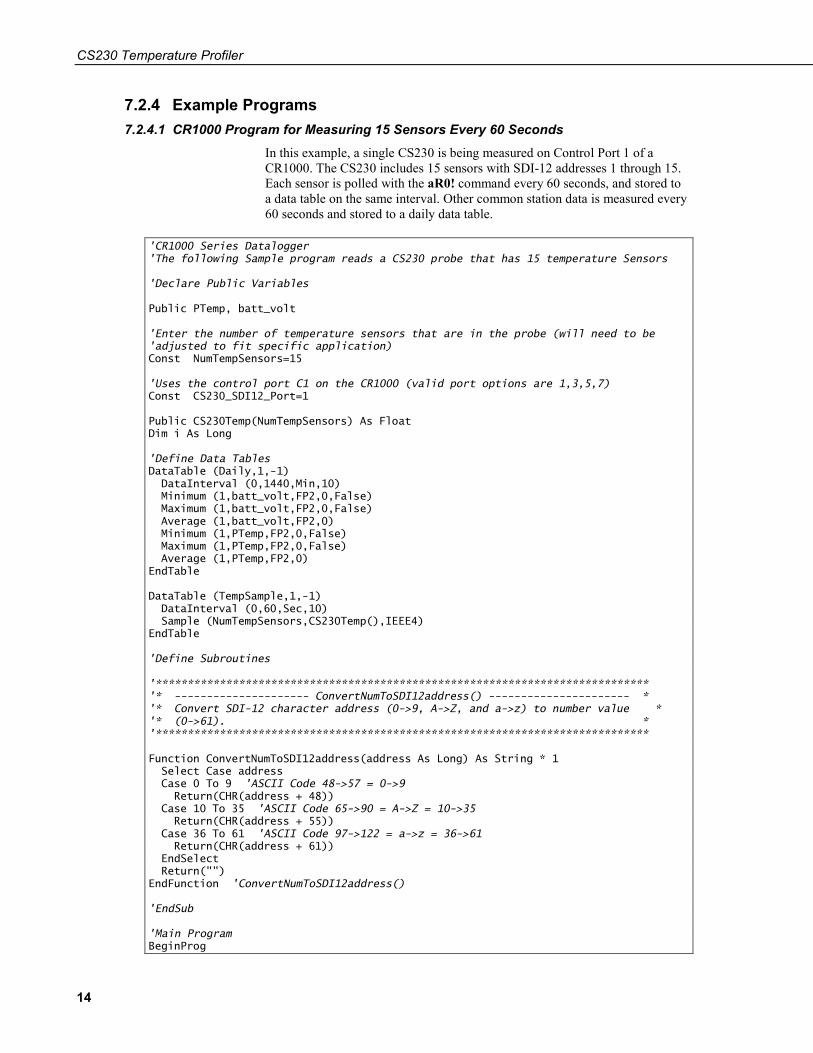
7.2.4 Example Programs 7.2.4.1 CR1000 Program for Measuring 15 Sensors Every 60 Seconds
In this example, a single CS230 is being measured on Control Port 1 of a CR1000. The CS230 includes 15 sensors with SDI-12 addresses 1 through 15. Each sensor is polled with the aR0! command every 60 seconds, and stored to a data table on the same interval. Other common station data is measured every 60 seconds and stored to a daily data table.
'CR1000 Series Datalogger 'The following Sample program reads a CS230 probe that has 15 temperature Sensors 'Declare Public Variables Public PTemp, batt_volt 'Enter the number of temperature sensors that are in the probe (will need to be 'adjusted to fit specific application) Const NumTempSensors=15 'Uses the control port C1 on the CR1000 (valid port options are 1,3,5,7) Const CS230_SDI12_Port=1 Public CS230Temp(NumTempSensors) As Float Dim i As Long 'Define Data Tables DataTable (Daily,1,-1) DataInterval (0,1440,Min,10) Minimum (1,batt_volt,FP2,0,False) Maximum (1,batt_volt,FP2,0,False) Average (1,batt_volt,FP2,0) Minimum (1,PTemp,FP2,0,False) Maximum (1,PTemp,FP2,0,False) Average (1,PTemp,FP2,0) EndTable DataTable (TempSample,1,-1) DataInterval (0,60,Sec,10) Sample (NumTempSensors,CS230Temp(),IEEE4) EndTable 'Define Subroutines '***************************************************************************** '* --------------------- ConvertNumToSDI12address() ---------------------- * '* Convert SDI-12 character address (0->9, A->Z, and a->z) to number value * '* (0->61). * '***************************************************************************** Function ConvertNumToSDI12address(address As Long) As String * 1 Select Case address Case 0 To 9 'ASCII Code 48->57 = 0->9 Return(CHR(address + 48)) Case 10 To 35 'ASCII Code 65->90 = A->Z = 10->35 Return(CHR(address + 55)) Case 36 To 61 'ASCII Code 97->122 = a->z = 36->61 Return(CHR(address + 61)) EndSelect Return("") EndFunction 'ConvertNumToSDI12address() 'EndSub 'Main Program BeginProg
CS230 Temperature Profiler
15
Scan (60,Sec,0,0) PanelTemp (PTemp,250) Battery (batt_volt) 'Read the current Temperature Value For i=1 To NumTempSensors SDI12Recorder (CS230Temp(i),CS230_SDI12_Port,ConvertNumToSDI12address(i),"R0!",1.0,0) Next CallTable Daily CallTable TempSample NextScan EndProg
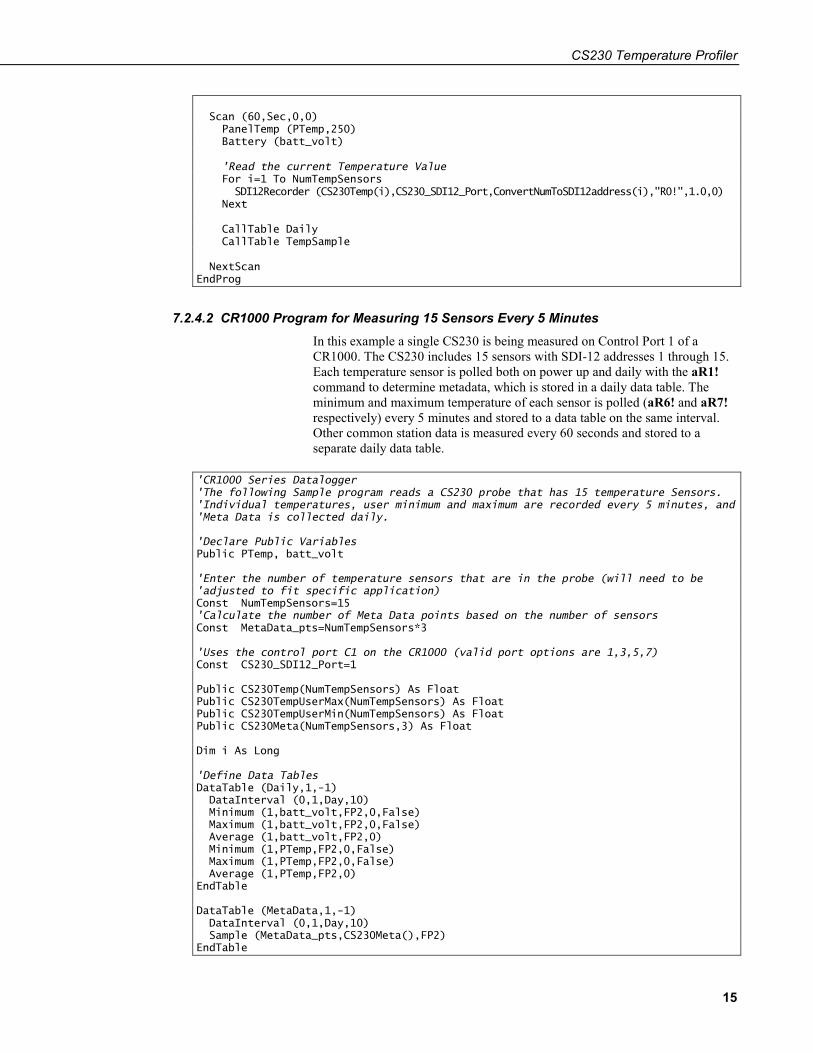
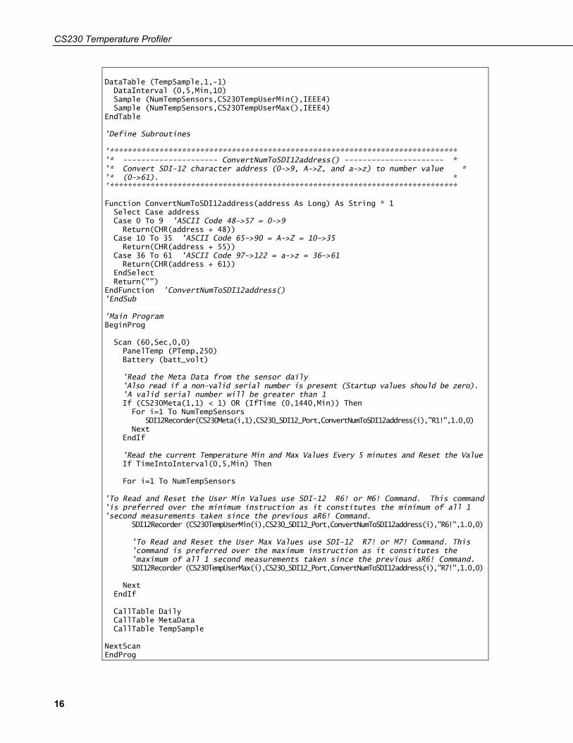
7.2.4.2 CR1000 Program for Measuring 15 Sensors Every 5 Minutes In this example a single CS230 is being measured on Control Port 1 of a CR1000. The CS230 includes 15 sensors with SDI-12 addresses 1 through 15. Each temperature sensor is polled both on power up and daily with the aR1! command to determine metadata, which is stored in a daily data table. The minimum and maximum temperature of each sensor is polled (aR6! and aR7! respectively) every 5 minutes and stored to a data table on the same interval. Other common station data is measured every 60 seconds and stored to a separate daily data table.
'CR1000 Series Datalogger 'The following Sample program reads a CS230 probe that has 15 temperature Sensors. 'Individual temperatures, user minimum and maximum are recorded every 5 minutes, and 'Meta Data is collected daily. 'Declare Public Variables Public PTemp, batt_volt 'Enter the number of temperature sensors that are in the probe (will need to be 'adjusted to fit specific application) Const NumTempSensors=15 'Calculate the number of Meta Data points based on the number of sensors Const MetaData_pts=NumTempSensors*3 'Uses the control port C1 on the CR1000 (valid port options are 1,3,5,7) Const CS230_SDI12_Port=1 Public CS230Temp(NumTempSensors) As Float Public CS230TempUserMax(NumTempSensors) As Float Public CS230TempUserMin(NumTempSensors) As Float Public CS230Meta(NumTempSensors,3) As Float Dim i As Long 'Define Data Tables DataTable (Daily,1,-1) DataInterval (0,1,Day,10) Minimum (1,batt_volt,FP2,0,False) Maximum (1,batt_volt,FP2,0,False) Average (1,batt_volt,FP2,0) Minimum (1,PTemp,FP2,0,False) Maximum (1,PTemp,FP2,0,False) Average (1,PTemp,FP2,0) EndTable DataTable (MetaData,1,-1) DataInterval (0,1,Day,10) Sample (MetaData_pts,CS230Meta(),FP2) EndTable
CS230 Temperature Profiler
16
DataTable (TempSample,1,-1) DataInterval (0,5,Min,10) Sample (NumTempSensors,CS230TempUserMin(),IEEE4) Sample (NumTempSensors,CS230TempUserMax(),IEEE4) EndTable 'Define Subroutines '***************************************************************************** '* --------------------- ConvertNumToSDI12address() ---------------------- * '* Convert SDI-12 character address (0->9, A->Z, and a->z) to number value * '* (0->61). * '***************************************************************************** Function ConvertNumToSDI12address(address As Long) As String * 1 Select Case address Case 0 To 9 'ASCII Code 48->57 = 0->9 Return(CHR(address + 48)) Case 10 To 35 'ASCII Code 65->90 = A->Z = 10->35 Return(CHR(address + 55)) Case 36 To 61 'ASCII Code 97->122 = a->z = 36->61 Return(CHR(address + 61)) EndSelect Return("") EndFunction 'ConvertNumToSDI12address() 'EndSub 'Main Program BeginProg Scan (60,Sec,0,0) PanelTemp (PTemp,250) Battery (batt_volt) 'Read the Meta Data from the sensor daily 'Also read if a non-valid serial number is present (Startup values should be zero). 'A valid serial number will be greater than 1 If (CS230Meta(1,1) < 1) OR (IfTime (0,1440,Min)) Then For i=1 To NumTempSensors SDI12Recorder(CS230Meta(i,1),CS230_SDI12_Port,ConvertNumToSDI12address(i),"R1!",1.0,0) Next EndIf 'Read the current Temperature Min and Max Values Every 5 minutes and Reset the Value If TimeIntoInterval(0,5,Min) Then For i=1 To NumTempSensors 'To Read and Reset the User Min Values use SDI-12 R6! or M6! Command. This command 'is preferred over the minimum instruction as it constitutes the minimum of all 1 'second measurements taken since the previous aR6! Command. SDI12Recorder (CS230TempUserMin(i),CS230_SDI12_Port,ConvertNumToSDI12address(i),"R6!",1.0,0) 'To Read and Reset the User Max Values use SDI-12 R7! or M7! Command. This 'command is preferred over the maximum instruction as it constitutes the 'maximum of all 1 second measurements taken since the previous aR6! Command. SDI12Recorder (CS230TempUserMax(i),CS230_SDI12_Port,ConvertNumToSDI12address(i),"R7!",1.0,0) Next EndIf CallTable Daily CallTable MetaData CallTable TempSample NextScan EndProg
CS230 Temperature Profiler
17
7.3 Changing the SDI-12 Address Using LoggerNet and a Datalogger
It is possible to connect multiple CS230 or other SDI-12 sensors to a single datalogger control port. Each temperature sensor in the CS230, or output from another SDI-12 device must have a unique SDI-12 address (see TABLE 7-4, SDI-12 Addresses and Positions (p. 10)).
The factory-set SDI-12 addresses for the CS230 start at 1 and continue until the last temperature sensor. The CS230 SDI-12 address is changed in software by issuing the aAb! command to the CS230 over the SDI-12 interface, where a is the current address and b is the new address. The current addresses of the individual sensors can be found by issuing the a! command.
Campbell Scientific dataloggers (with the exception of the CR5000) support a method of directly interacting with SDI-12 sensors via a terminal emulator. This allows you to get confirmation that the change of address has worked, using the a! command. This can be done using a computer running LoggerNet to issue any valid SDI-12 command through the datalogger to the CS230 as described in the following sections.
7.3.1 CR1000 and CR800 Series Dataloggers 1. Connect the CS230 to the datalogger using Control Port C1 or C3 as
described in Section 7.1, Wiring (p. 6). Be sure the datalogger is not running a program that contains the SDI12Recorder() instruction on the port used.
2. Assuming that the datalogger is configured in Setup and able to communicate via LoggerNet, navigate to the Connect screen. Select Terminal Emulator under the Datalogger menu. The Terminal Emulator window will open. In the Select Device menu, located in the lower left-hand side of the window, select the station.
3. Click on the Open Terminal button.
4. Press the <enter> key until the datalogger responds with the CR800 prompt. Type SDI12 and select the appropriate port.
5. If the CS230 temperature sensor addresses are unknown, then conduct a query for each sensor’s current SDI-12 address with the aI! command. If no characters are typed within 12 seconds, then the mode is exited. Once a complete list of addresses is gathered, you will know what block of addresses are required to readdress the CS230. You will also be able to request the related metadata so that sensor locations are confirmed. Be sure to reference TABLE 7-4, SDI-12 Addresses and Positions (p. 10), for a list of appropriate addresses.
CS230 Temperature Profiler
18
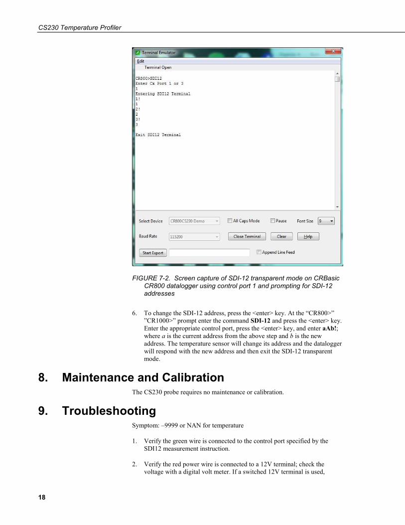
FIGURE 7-2. Screen capture of SDI-12 transparent mode on CRBasic CR800 datalogger using control port 1 and prompting for SDI-12 addresses
6. To change the SDI-12 address, press the <enter> key. At the “CR800>” ”CR1000>” prompt enter the command SDI-12 and press the <enter> key. Enter the appropriate control port, press the <enter> key, and enter aAb!; where a is the current address from the above step and b is the new address. The temperature sensor will change its address and the datalogger will respond with the new address and then exit the SDI-12 transparent mode.
8. Maintenance and Calibration The CS230 probe requires no maintenance or calibration.
9. Troubleshooting Symptom: –9999 or NAN for temperature
1. Verify the green wire is connected to the control port specified by the SDI12 measurement instruction.
2. Verify the red power wire is connected to a 12V terminal; check the voltage with a digital volt meter. If a switched 12V terminal is used,
CS230 Temperature Profiler
19
temporarily connect the red wire to a 12V terminal (non-switched) for test purposes.
Symptom: Sensor won’t respond to command
1. Expected address not used or has been changed.
a. Confirm all addresses in use with the aI! command to determine the individual addresses of each temperature sensor.
2. Expected sensor address has been to match another sensor address already in use.
a. When readdressing temperature sensors, you must avoid giving multiple sensors the same address. If this does occur, you will no longer be able to communicate with these sensors. Use the aA{! command, where a is the affected address. This will reset the affected sensors to their factory configured address value.

CS230 Temperature Profiler
20

Campbell Scientific Companies
Campbell Scientific, Inc. 815 West 1800 North Logan, Utah 84321 UNITED STATES
www.campbellsci.com • [email protected]
Campbell Scientific Africa Pty. Ltd. PO Box 2450
Somerset West 7129 SOUTH AFRICA
www.campbellsci.co.za • [email protected]
Campbell Scientific Southeast Asia Co., Ltd. 877/22 Nirvana@Work, Rama 9 Road
Suan Luang Subdistrict, Suan Luang District Bangkok 10250
THAILAND www.campbellsci.asia • [email protected]
Campbell Scientific Australia Pty. Ltd. PO Box 8108
Garbutt Post Shop QLD 4814 AUSTRALIA
www.campbellsci.com.au • [email protected]
Campbell Scientific (Beijing) Co., Ltd. 8B16, Floor 8 Tower B, Hanwei Plaza
7 Guanghua Road Chaoyang, Beijing 100004
P.R. CHINA www.campbellsci.com • [email protected]
Campbell Scientific do Brasil Ltda. Rua Apinagés, nbr. 2018 ─ Perdizes CEP: 01258-00 ─ São Paulo ─ SP
BRASIL www.campbellsci.com.br • [email protected]
Campbell Scientific Canada Corp. 14532 – 131 Avenue NW Edmonton AB T5L 4X4
CANADA www.campbellsci.ca • [email protected]
Campbell Scientific Centro Caribe S.A. 300 N Cementerio, Edificio Breller
Santo Domingo, Heredia 40305 COSTA RICA
www.campbellsci.cc • [email protected]
Campbell Scientific Ltd. Campbell Park
80 Hathern Road Shepshed, Loughborough LE12 9GX
UNITED KINGDOM www.campbellsci.co.uk • [email protected]
Campbell Scientific Ltd. 3 Avenue de la Division Leclerc
92160 ANTONY FRANCE
www.campbellsci.fr • [email protected]
Campbell Scientific Ltd. Fahrenheitstraße 13
28359 Bremen GERMANY
www.campbellsci.de • [email protected]
Campbell Scientific Spain, S. L. Avda. Pompeu Fabra 7-9, local 1
08024 Barcelona SPAIN
www.campbellsci.es • [email protected]
Please visit www.campbellsci.com to obtain contact information for your local US or international representative.