CS Unitec Air Powered Concrete Cutting Chainsaw
22
© Copyright ICS 2003 P/N 71702 July 03 AIR POWERED CONCRETE CUTTING CHAINSAW Model # CS71773 OPERATOR’S MANUAL CS Unitec 22 Harbor Ave Norwalk CT 06850 USA (203) 853-9522 toll free: (800)-700-5919 fax: (203-)853-9921 e mail: [email protected] www.csunitec.com Assembled to Specifications by ICS, Blount Inc.
-
Upload
cs-unitec -
Category
Technology
-
view
862 -
download
1
Transcript of CS Unitec Air Powered Concrete Cutting Chainsaw
© Copyright ICS 2003 P/N 71702 July 03
AIR POWERED CONCRETE CUTTING
CHAINSAW
Model # CS71773
OPERATOR’S MANUAL
CS Unitec 22 Harbor Ave
Norwalk CT 06850 USA (203) 853-9522
toll free: (800)-700-5919 fax: (203-)853-9921
e mail: [email protected]
www.csunitec.com
Assembled to Specifications by ICS, Blount Inc.

Concrete Cutting Chain Saw Operators Manual
2
TABLE OF CONTENTS SYMBOLS & LABELS 3 SAFETY 4 TECHNICAL SPECIFICATIONS 6 SET-UP 7 OPERATION 9 TROUBLESHOOTING 12 MAINTENANCE 13 REFERENCE 14

Concrete Cutting Chain Saw Operators Manual
3
SYMBOLS & LABELS
THE FOLLOWING SYMBOLS & LABELS MAY BE FOUND IN THIS MANUAL OR ON THE SAW
A potentially hazardous situation exists which, if not avoided, could result in death or serious personal injury.
A potentially hazardous situation exists which, if not avoided, may result in minor or moderate personal injury.
Read the operator’s manual carefully and understand the contents before you use this equipment.
Always use:
• Protective helmet • Ear protection • Protective glasses or full face protection
Wear hand protection
WARNING
CAUTION

Concrete Cutting Chain Saw Operators Manual
4
SAFETY THE FOLLOWING WARNING SYMBOL APPLIES TO ALL THE ITEMS LISTED ON THIS PAGE
A potentially hazardous situation exists which, if not avoided, could result in death or serious personal injury.
Note: Chain breakage can result in high-speed ejection of parts, which can result in death or serious personal injury to operators or bystanders. The items listed immediately below are critical to minimizing the risk of chain breakage and injury. • DO NOT operate saw with a damaged, modified, or broken side cover or baffle drain. The side
cover and baffle drain provides protection against contact with moving parts, ejected debris, broken chain, thrown water and concrete slurry.
• DO NOT exceed 90 psi (6 bar) and 124 cfm (3.5 m3/min) operating pressure and volume.
• DO NOT install or run the chain backwards. The bumper should lead the segment into the
cut.
• DO NOT run the saw motor backwards. The chain should travel away from the operator on the top of the bar and return on the bottom of the bar.
• DO NOT insert the diamond chainsaw into a slot narrower than the chain segments. Rapid
pushback might occur. Ref: Most diamond segments are .225 inches wide (5.72 mm).
• DO NOT use the side cover as a replacement side cover on any other saw.
• NEVER run a diamond chainsaw upside-down. Concrete debris can fly back into the operator’s face.
• NEVER cut ductile iron pipe with the diamond chainsaw. Segment loss or chain breakage
may occur.
WARNING
Bumper

Concrete Cutting Chain Saw Operators Manual
5
SAFETY
THE FOLLOWING CAUTION SYMBOL APPLIES TO ALL ITEMS LISTED IMMEDIATELY BELOW A potentially hazardous situation exists which, if not avoided, may result in minor or moderate personal injury.
• Always disconnect the air supply when performing maintenance on the saw. • SealPro® diamond chains require a minimum water pressure of 20 psi (1.4 bar). Insufficient
water supply may result in excessive wear to the diamond chain, which can lead to loss of strength and diamond chain breakage.
• When operating a compressor with greater than 90 psi (6 bar) it is recommended to use a
"service unit with pressure regulator" in the line to prevent over speeding the saw.
GENERAL SAFETY PRECAUTIONS • Always wear protective clothes, including hard hat, eye protection, hearing protection, and gloves. • Always operate tool with solid footing and handgrip. • Slurry can be very slick. Remove or control to prevent yourself or others from slipping while cutting. • Always work in a cleared area.
• Be sure there are no obstructions (plumbing, electrical conduit, air ducts). • Set up a well-marked safety zone with a roped boundary and clear signs. • Breathing exhaust gasses is dangerous. Provide ventilation in closed areas. • To avoid electrocution, check for live electrical wiring near cutting area.
CAUTION

Concrete Cutting Chain Saw Operators Manual
6
TECHNICAL SPECIFICATIONS
Weight without bar and chain
29 lbs (13.15 kg)
Length
20 in (58.5 cm)
Height
10.5 in (26.5 cm)
Width
12 in (30.48 cm)
Air Motor Power
6.5 Horse Power (5 KW)
Air Supply Requirements (maximum)
90psi (6 bar)
124 cfm (3.5 m³/min)
Water Pressure Requirements
Minimum: 20psi (1.4 bar)
Water Flow Requirements
1 gpm(4 lpm) minimum
Operating Speed
5,700 rpm (average free running)
4,900 sfm (average free running chain)
Vibration
Front handle: 4 m/s2 Rear handle: 8 m/s2
Ref. ISO standard no. 7505
When operating a compressor with pressure greater than 90 psi (6 bar) it is recommended to use a "service unit with pressure regulator" in the line to prevent over speeding the saw.
Concrete Cutting Chain Saw Operators Manual
7
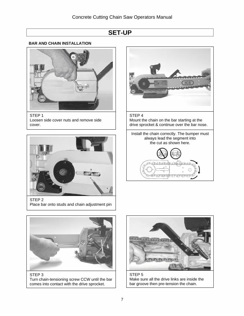
SET-UP BAR AND CHAIN INSTALLATION
STEP 1 Loosen side cover nuts and remove side cover.
STEP 3 Turn chain-tensioning screw CCW until the bar comes into contact with the drive sprocket.
STEP 4 Mount the chain on the bar starting at the drive sprocket & continue over the bar nose.
STEP 5 Make sure all the drive links are inside the bar groove then pre-tension the chain.
Install the chain correctly. The bumper must always lead the segment into
the cut as shown here.
STEP 2 Place bar onto studs and chain adjustment pin

Concrete Cutting Chain Saw Operators Manual
8
SET-UP BAR AND CHAIN INSTALLATION Note 1: Do not “over tension” the chain. Loss of power will result. It is normal for the drive links to hang underneath the bar. The chain should be tight but be able to be pulled around the bar by hand. Note 2: To prevent chain tensioner breakage, be sure the side cover nuts are tightened to approximately 20 ft-lbs (27 Nm)
STEP 7 Install the side cover over the bar studs and install side cover nuts. Finger tighten only.
STEP 8 Tension the chain. The chain should be tight but able to be pulled around the bar by hand. See Note 1
STEP 9 Lift up on the nose of the bar and firmly tighten the side cover nuts. See Note 2
STEP 6 Install bar clamp plate over the bar studs.

Concrete Cutting Chain Saw Operators Manual
9
OPERATION PRE-CUT CHECKLIST • Proper Chain Installation: The bumper should lead the segment into the cut. • Proper Chain Tension: The chain should be tight but easily pulled around the bar by hand. • Adequate Water Supply and Pressure:
Minimum Flow: 1 gpm (4 lpm) Recommended Water Pressure: 20 psi (1.4 bar)
• Proper Air Supply to the Saw: Maximum PSI: 90 (6 bar) Maximum CFM: 124 cfm (3.5 M3/min)
Blow the air supply line clear before connecting it to the saw . Install dirt and water separators upstream of the saw to prevent rust and condensation from forming in the air lines.
• Motor Lubricator:
Check oil level, if necessary, fill with resin and acid-free SAE 5 W to SAE 10 W oil. In winter or when using very moist air, use antifreeze lubricant, such as "Killfrost" "BP Energol AX10" or "Kompranol"
• The chain should travel away from the operator on the top of the bar during operation. PLANNING THE CUT • Select the proper chain for the material being cut. • Outline the cut with a permanent marker for a visual cutting guide. • Avoid pinching the bar and chain. Always cut the bottom of an opening first, then top, and then the
sides. Save the easiest cut for last. • Be sure cut concrete cannot fall and injure operator or bystanders. • Check for live electrical wiring near the cutting area or in the concrete to avoid electrocution which
can result in death or serious personal injury.

Concrete Cutting Chain Saw Operators Manual
10
OPERATION Operating The Concrete Cutting Chainsaw 1. Plunge cut instead of starting at the top of the wall. This will reduce chatter, extend diamond life,
create a straighter cut and more quickly enable the use of the Wallwalker®. 2. Always operate a diamond chainsaw at full throttle. Apply enough feed force so that the free running
RPM drops 20 to 30%. If too much force is applied, the saw will lug or stall. The chain will not have enough speed to cut effectively. If too little feed force is applied, the diamonds will skid and glaze over.
3. For straight cuts use the “step cut” method. First score the entire cut line with the nose of the bar
approximately ½ inch (12mm) to 1 inch (25mm) deep. Next, deepen the cut by about 2 inches (50 mm). This groove will help guide the bar for a straight cut. Then plunge all the way through and complete the cut using the Wallwalker®.
4. Use the Wallwalker® to cut efficiently and reduce user fatigue. The Wallwalker® is a lever system
that converts inward force to downward force and will develop a 4-to-1 mechanical advantage. To use correctly, plunge into the wall and simply engage the point of the Wallwalker® into the cut and push straight in. The Wallwalker® will force the saw to feed down.
Apply an upward force on the trigger handle to keep the Wallwalker® engaged properly, otherwise the Wallwalker® pick will skid, which will reduce the effectiveness. As the Wallwalker begins to rotate up, feed force is developed down the line of the intended cut. The feed force will increase as the Wallwalker reaches the end of its stroke. When the Wallwalker bottoms out, pull the saw out of the cut a few inches and allow the Wallwalker to spring back into its starting position. Re-engage the pick into the cut and repeat.
5. When cutting heavy rebar, slowly ”rock” the saw to help keep the diamonds exposed. Also, expect
less chain life when cutting heavy rebar. 6. Expect more chain stretch when making nose buried cuts for extended periods of time as the chain
does not have a chance to “sling” the slurry away from the nose of the bar. 7. If the saw begins to cut consistently crooked, turn the bar over and use the other side. Note: The
normal life of a guide bar is 2 to 3 chains. However, heavy rebar can shorten bar life too. 8. When using a new chain, you can increase the cutting speed by “opening up the diamonds”. Make a
few cuts in an abrasive material such as a cinder block.

Concrete Cutting Chain Saw Operators Manual
11
OPERATION SYSTEM CLEAN-UP 1. Run saw, with water on, for 15 seconds out of cut to flush slurry and debris from chain, bar and drive
sprocket. 2. Wash concrete slurry from saw assembly. 3. Remove bar and chain. Flush out chain tensioner assembly location with high water pressure and
lube with grease. 4. Clean all air fittings on saw and compressor. 5. When done cleaning saw, spray entire saw body, chain, bar, and drive sprocket with a light weight
penetrating oil. This will minimize rust and reduce slurry build up on saw assembly.

Concrete Cutting Chain Saw Operators Manual
12
TROUBLESHOOTING
• SLOW CHAIN SPEED - Be sure the compressor is providing the correct air pressure (90 psi = 6 bar)
and cubic feet per minute (124 cfm = 3.5 m3/min) • POOR CUTTING PERFORMANCE - Diamonds may be “glazed over”. Make a few cuts in an
abrasive material such as a cinder block to expose the diamonds. • PREMATURE CHAIN STRECH - Not enough water pressure. The recommended water pressure is
20 psi (1.4 bar) • CHAIN TENSIONER BREAKAGE - Side cover nuts are not tight enough. • WATER NOT FLOWING - Water hose is kinked, blockage in guide bar water ports, or supply is not
turned on. • Motor Does Not Start -
• Insufficient air supply. Check Compressor and air hose, valves, and air inlet screen for blockage. • Chain tension is too tight. loosen chain tension. • Iced exhaust. wait until ice thaws, then use anti-freeze lubricant • Vanes sticky. Apply lubricant directly to saw air inlet and blow motor clear. Repeat if nessary.
see maintenance instructions

Concrete Cutting Chain Saw Operators Manual
13
MAINTENANCE DRIVE SPROCKET REMOVAL AND INSTALLATION Drive Sprocket Removal Step 1. Prevent the sprocket from rotating by inserting scrench or screw driver though the holes in the sprocket and the hole in the saw body. Step 2. Loosen the Trantorque® using a 7/8” box end wrench. Note: If Trantorque® is stuck, tap lightly with a brass hammer. Drive Sprocket Installation Step 1. Slide Trantorque® shaft adapter onto drive shaft until it bottoms out on the end of the shaft. Note: Do not lubricate Trantorque® or shaft as slippage may occur. Step 2. Slide drive sprocket onto the Trantorque® until it bottoms on the Trantorque®. Step 3 Finger tighten Trantorque® shaft adapter. Step 4. Stop the sprocket from rotating by inserting scrench
or screw driver though the holes in the sprocket and the hole in the saw body.
Step 5. Tighten the Trantorque® shaft adapter with a torque wrench
and a 7/8” socket to 200 in-lbs (22.6 Nm). When a torque wrench is not available, use a 7/8" box end wrench and tighten one half turn past finger tight.
Note: Do not turn around or reverse the direction of the drive sprocket to extend sprocket tooth life. Damage to chain or drive links may occur.

Concrete Cutting Chain Saw Operators Manual
14
AIR MOTOR MAINTENANCE Only proper maintenance can ensure consistant saw performance, reduction in wear, and thus, a decrease in operation costs and an increase in service life. Service life and performance of the chain saw are determined by:
1. Degree of air purity 2. Lubrication 3. Maintenance
Prior to operating the saw be sure to:
1. Blow the air hose clear prior to connecting it to the saw. Install dirt and water separators upstream of the saw.
2. Install an air lubricator upstream of the saw and fill it with SAE 5 W to SAE 10 W oil. Optimum lubrication significantly prolongs service life.
3. Regularly check and clean the air inlet screen. Replace wear parts - in particular the motor vanes. It is suggested to replace the motor vanes if their width is less than 1.083 in. (27.5 mm).
KEEP TOOL CLEAN
MAINTENANCE

Concrete Cutting Chain Saw Operators Manual
15
SPARE PARTS LIST

Concrete Cutting Chain Saw Operators Manual
16
Item Qty. Description Order-Number Remarks for customer
1 1 Motor housing cpl. 5 1018 1910 with item 2 2 1 Screw 5 1018 2060 3 1 End plate 5 1018 1100 4 1 Groved ball bearing 9 1002 0030 16 004 DIN 625 5 1 Snapring 9 1703 0130 42x1,75 DIN 472 6 1 Spacer 1 2134 1090 7 1 Cylinder bushing 5 1018 1020 8 1 Adapter sleeve 9 1630 0620 4x12 DIN 1481 9 1 Adapter sleeve 9 1630 0620 4x12 DIN 1481 10 1 Rotor 5 1018 1030 11 7 Vane 5 1018 1050 12 1 End plate 5 1018 1110 13 1 Groved ball bearing 9 1005 0250 6304-2RS 1 14 1 Snapring 9 1703 0240 52x2 DIN 472 15 1 Spacer 1 2134 1090 16 1 Belleville spring 9 1802 0600 17 1 Motor cover 5 1018 1330 18 6 Fillister head screw 9 1112 4020 M6x16 DIN 7984 1 Governor cpl. 5 1018 2000 item 21-26
21 1 Segment 5 1018 2020 22 2 Governor weight 2 1901 2030 23 2 Cylinder bolt 9 1619 0150 3m6x18 DIN 7 24 1 Governor bolt 2 1901 2040 25 1 Compression spring 9 1803 0340 26 2 Nut 9 1203 0030 M 5 DIN 934 1 Plate cpl. 5 1018 1700 Item 31-37
31 1 Plate 5 1018 1770 32 1 Silence plate cpl. 5 1018 1730 33 1 Tube 5 1018 1780 34 1 Compression spring 9 1803 4510 35 1 Block cap 5 1018 1790 36 1 Toothed washer 9 3318 0020 A 6,4 DIN 6797 37 1 Nut 9 1210 0160 M 6 DIN 985 38 4 Fillister head screw 9 1112 4140 M6x35 DIN 984 39 1 Safety cover 5 1018 1820 40 1 cover 5 1017 3160 41 1 O-Ring 9 1901 3130 31x2 42 4 Fillister head screw 9 1112 4020 M6x16 DIN7984 43 2 Counter sunk bolt 91113 7070 M10x30 DIN 7991
SPARE PARTS LIST

Concrete Cutting Chain Saw Operators Manual
17
Item Qty.
Description Order-Number Remarks for Customer
201 1 Valve 5 1018 6210 205 1 Bolt 9 1171 9460 206 1 Sealing ring 9 1903 0990 207 1 Ball 9 1017 0070 Ø 20 DIN 5401 208 1 Compression spring 9 1803 3490 D-212D 209 1 Valve insert 5 1018 3150 216 1 Valve lifter 9 1637 2160 217 1 O-Ring 9 1901 2210 4x1 218 1 Compression spring 9 1803 3990 D-163 219 1 Compression spring 9 1803 3980 D-103 220 1 Pawl 5 1023 6040 221 1 Double notched 9 1641 0030 Kerpin S11 5x30 222 1 Valve lever 5 1023 3030 224 1 Double notched 9 1641 0040 Kerpin S11 6x30
SPARE PARTS LIST

Concrete Cutting Chain Saw Operators Manual
18
Item Qty.
Description Order-Number Remarks for Customer
1 Air motor 5 1018 1000 see separate list 1 Valve cpl. 5 1018 6000 see separate list 1 Connection 5 1018 9000 see separate list
Spare Parts List

Concrete Cutting Chain Saw Operators Manual
19
Item Qty.
Description Order-Number Remarks for Customer
100 1 Tube 5 1018 3400 101 2 O-Ring 9 1901 2270 22x1,5 102 2 Nipple 9 2205 1760 103 1 Level 5 1018 6900
104 4 Thoothed washer 9 3318 0070 A8,4 DIN 6797
106 4 Fillister head screw 9 1110 5070 M8x50 DIN 912
107 4 Nut 9 1210 0010 M8 DIN 985
SPARE PARTS LIST

Concrete Cutting Chain Saw Operators Manual
20
Item Qty.
Description Order-Number
44 1 Chain tensioner kit CS70636
45 1 Guard flap assembly CS72408
46 1 Sprocket assembly CS71105
47 1 Trantorque shaft adaptor CS70618
48 1 WallWalker® replacement kit CS70641
49 1 Side cover replacement kit CS70990
50 2 Side cover retaining nuts (2 ea.) CS70639
51 1 Bar retaining plate CS70628
52 2 Bar mounting studs (1 ea.) CS72349
53 1 Bar mount cover plate CS70627
SPARE PARTS LIST

Concrete Cutting Chain Saw Operators Manual
21
REFERENCE APPROXIMATE CUTTING RATES
Material Cutting Rate
6 in (15cm) concrete 5 lineal inches per minute (12cm/min) 6 in (15cm) red brick 10 lineal inches per minute (25cm/min)
#4 (12mm) rebar 10-20 seconds through each piece
INCH-FOOT DEFINITION An in-ft is a measure of how much material is to be cut. An in-ft is defined as: depth in inches times length in feet. Example: How many in-ft are in this doorway? 1. Determine the depth of the cut in inches.
For this example, 8 inches.
2. Determine the length of the cut in feet. 3+7+3+7=20 feet
3. Multiply the two numbers 8 in x 20 ft = 160 in-ft
1sq-m = 129 in-ft

Concrete Cutting Chain Saw Operators Manual
22