CS 475 Lecture 5 - University of...
35
Thursday, September 8 CS 475 Networks - Lecture 5 1 Lecture 5 Homework 2 posted, due September 15. Reminder: Homework 1 due today. Questions?
Transcript of CS 475 Lecture 5 - University of...

Thursday, September 8 CS 475 Networks - Lecture 5 1
Lecture 5
Homework 2 posted, due September 15. Reminder: Homework 1 due today. Questions?

Thursday, September 8 CS 475 Networks - Lecture 5 2
Outline
Chapter 2 - Getting Connected
2.1 Perspectives on Connecting
2.2 Encoding
2.3 Framing
2.4 Error Detection
2.5 Reliable Transmission
2.6 Ethernet
2.7 Wireless
2.8 Summary

Thursday, September 8 CS 475 Networks - Lecture 5 3
Error Detection
Bit errors in a frame will occur. How do we detect (and then recover) from them? We look at error detection first.
We detect errors by adding redundant information. We could transmit duplicate frames. If the frames differ on reception, one (or both) frames contains an error. This is inefficient (and not that reliable).
We will look at the two-dimensional parity, checksum, and cyclic redundancy check (CRC) error detection methods.

Thursday, September 8 CS 475 Networks - Lecture 5 4
Two-Dimensional Parity
Two-dimensional parity is often used with 7-bit codes (ASCII). It requires the addition of a parity byte (and 1 parity bit per word).
Two-dimensional parity catches all 1, 2, and 3 bit errors (and most 4 bit errors). Fig 2.14: 2D Parity
(Even Parity)

Thursday, September 8 CS 475 Networks - Lecture 5 5
Two-Dimensional Parity
PC serial port hardware can be configured to transmit and receive using 1-D parity.
The settings must be identical on both ends of the link.
Windows Serial PortProperties Window

Thursday, September 8 CS 475 Networks - Lecture 5 6
Internet Checksum Algorithm
Checksums are not used at the link layer, but are used at the higher layers in the TCP/IP stack. The checksum algorithm is easy to implement in software.
In the Internet (TCP/IP) checksum algorithm, data is treated as 16-bit integers. The integers are added using ones complement arithmetic. The ones complement of the sum is sent as the checksum.

Thursday, September 8 CS 475 Networks - Lecture 5 7
Internet Checksum Algorithm
In ones complement addition any carry out of the most significant bit is added back in at the least significant position.
Example: Compute the 8-bit check sum of 11000011, 10101010, 01110111 using the Internet checksum algorithm.
1100001110101010
01101101 1
01101110
0110111001110111
11100101
Checksum is00011010
A carry wrap around.
The checksum is theones complement (inverse)of the sum.Final sum.

Thursday, September 8 CS 475 Networks - Lecture 5 8
Internet Checksum Algorithm
At the receiver all words are added (including the checksum) using ones complement arithmetic. If there are no errors the sum will be all 1s (11111111 in the previous example).
The Internet checksum algorithm uses only a small number of extra bits (16 for a message of any size), but it is relatively weak.
Experience has shown that the algorithm is sufficient as long as stronger error detection (CRC) is used at the link layer.

Thursday, September 8 CS 475 Networks - Lecture 5 9
Cyclic Redundancy Check
The CRC algorithm is based on polynomial division. The bits in the message are treated as coefficients of a polynomial. For example, the four bit message 1011 represents:
M(x) = 1 x3 + 0 x2 + 1 x1 + 1 = x3 + x + 1
Note that most messages are thousands of bits long and would represent polynomials of high degree.

Thursday, September 8 CS 475 Networks - Lecture 5 10
Cyclic Redundancy Check
To calculate a CRC, the sender and receiver agree on a divisor polynomial, C(x)
Standard divisor polynomials are known to give good results. (Ethernet uses CRC-32).
CRC C(x)
CRC-8 x8 + x2 + x + 1
CRC-10 x10 + x9 + x5 + x4 + x + 1
CRC-12 x12 + x11 + x3 + x2 + 1
CRC-16 x16 + x12 + x2 + 1
CRC-CCITT x16 + x12 + x5 + 1
CRC-32 x32 + x26 + x23 + x22 + x16 + x12 + x11 + x10 + x8 + x7 + x5 + x4 + x2 + x + 1

Thursday, September 8 CS 475 Networks - Lecture 5 11
Cyclic Redundancy Check
To compute the k-bit CRC:
1)Multiply M(x) by xk (add k zeros at the end of the message). Call this message T(x).
2)Divide T(x) by C(x) and find the remainder.
3)Subtract the remainder from T(x).
In performing the division, exclusive-or is used instead of subtraction. Polynomials of equal order can always be divided.
The result is the original message followed by the remainder in step 2).
Thursday, September 8 CS 475 Networks - Lecture 5 12
Cyclic Redundancy Check
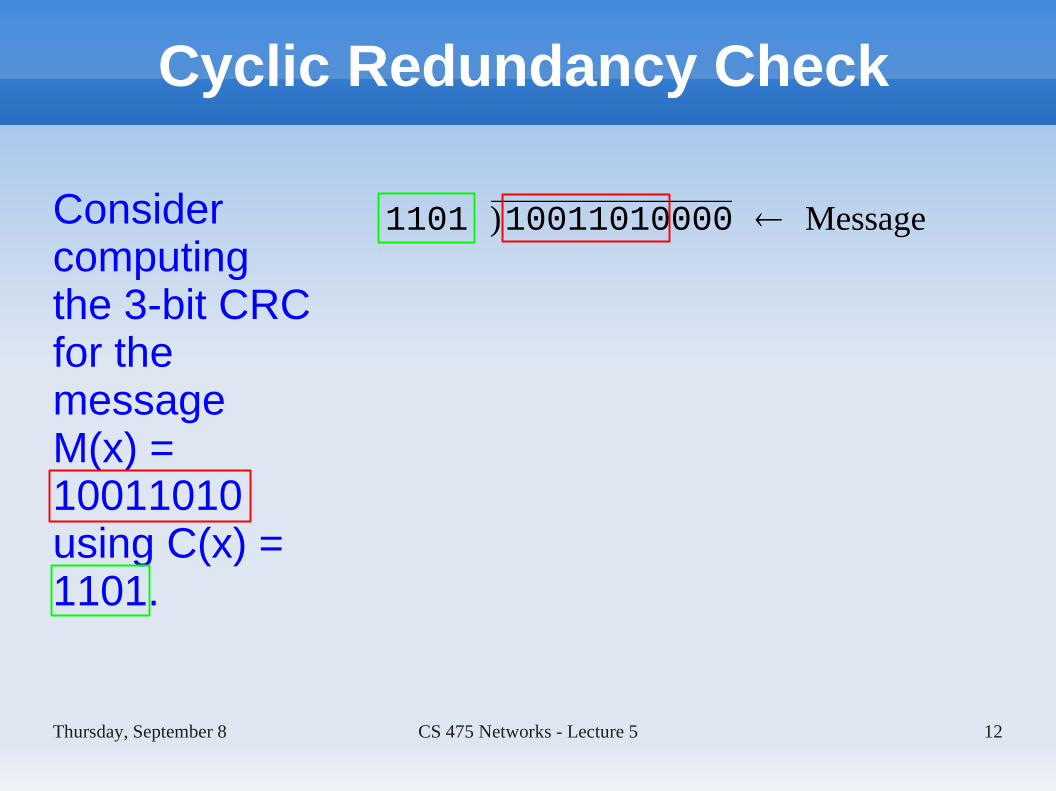
Consider computing the 3-bit CRC for the message M(x) = 10011010 using C(x) = 1101.
1101 )10011010000 Message

Thursday, September 8 CS 475 Networks - Lecture 5 13
Cyclic Redundancy Check
11101 )10011010000 Message
1101100

Thursday, September 8 CS 475 Networks - Lecture 5 14
Cyclic Redundancy Check
111101 )10011010000 Message
110110011101100

Thursday, September 8 CS 475 Networks - Lecture 5 15
Cyclic Redundancy Check
1111101 )10011010000 Message
11011001110110001101101

Thursday, September 8 CS 475 Networks - Lecture 5 16
Cyclic Redundancy Check
11111101 )10011010000 Message
1101100111011000110110111101110

Thursday, September 8 CS 475 Networks - Lecture 5 17
Cyclic Redundancy Check
111111101 )10011010000 Message
110110011101100011011011110111001101
1
Thursday, September 8 CS 475 Networks - Lecture 5 18
Cyclic Redundancy Check
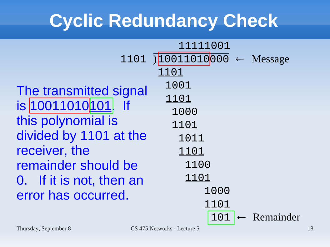
The transmitted signal is 10011010101. If this polynomial is divided by 1101 at the receiver, the remainder should be 0. If it is not, then an error has occurred.
111110011101 )10011010000 Message
110110011101100011011011110111001101
10001101101 Remainder

Thursday, September 8 CS 475 Networks - Lecture 5 19
Cyclic Redundancy Check
Although the CRC calculation appears complex, it can be computed in hardware using a shift register and exclusive-or gates.
Fig. 2.16: CRC calc. using a shift registerDivision by x3 + x2 + 1.

Thursday, September 8 CS 475 Networks - Lecture 5 20
Reliable Transmission
A link-level protocol that wants to deliver frames reliably must recover frames that have errors. This is usually done by using some combination of acknowledgments (ACKs) and timeouts.
Recovery algorithms that use ACKs and timeouts are known as automatic repeat request (ARQ) algorithms. We will examine three such algorithms.

Thursday, September 8 CS 475 Networks - Lecture 5 21
Stop-and-Wait
The simplest ARQ scheme is the stop-and-wait algorithm. After transmitting one frame the sender waits for an acknowledgment before transmitting the next frame. If the ACK does not arrive after a certain interval, the sender retransmits the original frame.

Thursday, September 8 CS 475 Networks - Lecture 5 22
Stop-and-Wait
If there are no errors, the timeline is as shown at right. (If an error is detected in the received frame, the receiver does not return an ACK. It waits for the frame to be retransmitted.)
Fig. 2.17: ACK received

Thursday, September 8 CS 475 Networks - Lecture 5 23
Stop-and-Wait
If a frame is lost, the sender automatically retransmits the frame after the timer has expired.
Fig. 2.17: Lost frame

Thursday, September 8 CS 475 Networks - Lecture 5 24
Stop-and-Wait
If the ACK is lost, the sender automatically retransmits the frame after the timer has expired.
The receiver can discard the duplicate frame, but must still send an ACK.
Fig. 2.17: Lost ACK

Thursday, September 8 CS 475 Networks - Lecture 5 25
Stop-and-Wait
If the ACK is delayed, the sender automatically retransmits the frame after the timer has expired.
The receiver can discard the duplicate frame, but must still send an ACK.
Fig. 2.17: Slow ACK

Thursday, September 8 CS 475 Networks - Lecture 5 26
Stop-and-Wait
To simplify detection of duplicate frames, the frame header includes a bit that alternates between 0 and 1.
If two consecutive 0 (or 1) frames are received, the receiver knows that the second frame is a duplicate.
Fig. 2.18: Stop and wait with1-bit sequence number.

Thursday, September 8 CS 475 Networks - Lecture 5 27
Stop-and-Wait
The main problem with the stop-and-wait algorithm is that it does not use the link to its full capacity.
A 1.5 Mbps link with a 45 ms RTT has a delay x BW product of 67.5 kb (8 kB). Assuming a 1 kB frame, stop-and-wait would only allow a throughput of
1 kB x 8 b/B / 45 ms = 182 kbps
This is only 1/8 of the link BW!

Thursday, September 8 CS 475 Networks - Lecture 5 28
Sliding Window
To fully utilize the available BW we allow the sender to transmit multiple frames in sequence.
On the 1.5 Mbps link from the previous slide we want the sender to transmit 8 frames and be ready to send the 9th as soon as the ACK for the first frame is received.
Fig. 2.19: Sliding Window Timeline
Thursday, September 8 CS 475 Networks - Lecture 5 29
Sliding Window
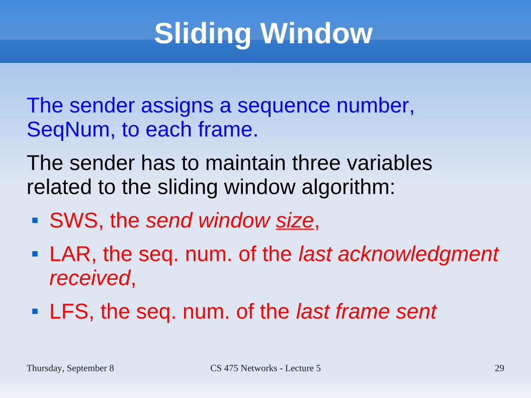
The sender assigns a sequence number, SeqNum, to each frame.
The sender has to maintain three variables related to the sliding window algorithm: SWS, the send window size, LAR, the seq. num. of the last acknowledgment
received, LFS, the seq. num. of the last frame sent

Thursday, September 8 CS 475 Networks - Lecture 5 30
Sliding Window
A new frame is sent (and LFS incremented) only if:
LFS – LAR ≤ SWS
Fig. 2.20: Sliding window on the sender.

Thursday, September 8 CS 475 Networks - Lecture 5 31
Sliding Window
The receiver maintains the following three variables: RWS, the receive window size, LAF, the sequence number of the largest
acceptable frame, LFR, the seq. num. of the last frame received

Thursday, September 8 CS 475 Networks - Lecture 5 32
Sliding Window
The receiver maintains the following invariant:
LAF – LFR ≤ RWS
Fig. 2.21: Sliding window on the receiver.

Thursday, September 8 CS 475 Networks - Lecture 5 33
Sliding Window
If the SeqNum of a received frame satisfies LFR < SeqNum ≤ LAF, the frame is accepted. If all frames with seq. numbers less than SeqNum have been ACKed then this frame is ACKed, LFR is set to SeqNum and LAF is set to LFR + RWS.
When frames are received out of order the details are a bit more complicated. See the text for details.

Thursday, September 8 CS 475 Networks - Lecture 5 34
Concurrent Logical Channels
ARPANET used a variation of stop-and-wait while still “keeping the pipe full”. It worked by using multiple logical channels and running stop-and-wait on each channel.
The header of each frame contained a 1-bit sequence number and the number of the logical channel.

Thursday, September 8 CS 475 Networks - Lecture 5 35
In-class Exericses
If time allows, start work on the homework problems.


![Esercitazione2 [modalit compatibilit ] - infoPLC · PLC Example 2 Francesca Fanfoni ... GREEN LIGHT Wait pedestrian request to stop the traffic ... pedestrian crossing to stop the](https://static.fdocuments.net/doc/165x107/5b1e53ed7f8b9a8a3a8b64d1/esercitazione2-modalit-compatibilit-plc-example-2-francesca-fanfoni-.jpg)