CS 3xx service guide v1
97
Confidential 1 CS Series Service Guide Version: 1.7 The Service Guide was written mainly for engineers. Please Do Not reproduce and duplicate.
Transcript of CS 3xx service guide v1

Confidential 1
CS Series Service Guide
Version: 1.7
The Service Guide was written mainly for engineers.
Please Do Not reproduce and duplicate.

Confidential 2
Outlines: Chapter 1. Introduction........................................................................................................................................... 4
Chapter 2. Innovative New Design ........................................................................................................................ 6
2-1. Difference between CS300 and CS310/320............................................................................................ 6
2-2. The new user-friendly adjustable TPH module....................................................................................... 6
2-3. Different TPH printing method (Compare to the photo printer)............................................................. 7
2-4. Four different kinds of thickness............................................................................................................. 7
2-5. Double-side printing mechanism (only in CS-300/CS-320)................................................................... 8
2-6. The new ADF apparatus.......................................................................................................................... 9
2-7. Enhanced cleaning roller....................................................................................................................... 10
2-8. Subsequent Printing Support................................................................................................................. 10
2-9. Encoding modules................................................................................................................................. 11
Chapter 3. Operating Theory................................................................................................................................ 12
3-1 Dye Diffusion Thermal Transfer (D2T2) ............................................................................................... 12
3-2 Hardware................................................................................................................................................ 13
Chapter 4. Disassembly & Assembly ................................................................................................................... 23
4-1 Safety Instructions..................................................................................................................................23
4-2 Tools ....................................................................................................................................................... 24
4-3 Do not disassemble This Parts ............................................................................................................... 25
4-4 Disassembly ........................................................................................................................................... 26
4-4-1 The case of card printer & chassis .............................................................................................. 26
4-4-2 Main Board ................................................................................................................................. 36
4-4-3 Motors......................................................................................................................................... 37
4-4-3-1 Flip Motor 1” & “Flip Motor 2........................................................................................ 39
4-4-3-2 Cam-Pinch Motor” and “Cam-TPH Motor ..................................................................... 40
4-4-3-3 Platen Motor .................................................................................................................... 41
4-4-3-4 Ribbon Motor .................................................................................................................. 42
4-4-4 LED and Sensor.......................................................................................................................... 43
4-4-4-1 Eject Sensors and USB module....................................................................................... 43
4-4-4-2 Ribbon LED .................................................................................................................... 45
4-4-4-3 Ribbon Sensor ................................................................................................................. 46
4-4-4-4 Flip_LE_Back & Flip_Jam_Back Sensor ....................................................................... 47
4-4-4-5 Flip_LE_Front & Flip_LE_Front Sensor ........................................................................ 48
4-4-4-6 LE_Back & Jam_Back Sensor ........................................................................................ 50
4-4-4-7 LE_TPH Sensor............................................................................................................... 51
4-4-4-8 Jam_TPH Sensor ............................................................................................................. 51
4-4-4-9 LE 4, 5 (LE_Front & Jam_Front Sensor)........................................................................ 53
4-4-4-10 Sensor_CAM_Pinch & Sensor_CAM_TPH ................................................................. 55
4-4-4-11 Smart Crad Module BD................................................................................................. 56
4-4-5 Power Board ............................................................................................................................... 58
4-4-6 ADF Module ............................................................................................................................... 60
Confidential 3 4-4-7 The Status/Trouble Shooting Indicator ....................................................................................... 63
4-4-8 TPH Linkage............................................................................................................................... 66
4-5 Assembly................................................................................................................................................ 72
4-5-1 Card Thinness Parameter ............................................................................................................ 72
4-5-2. Cam Position.............................................................................................................................. 74
Chapter 5: Adjustments ........................................................................................................................................ 76
5-1 Safety Instructions..................................................................................................................................76
5-2 Contents: ................................................................................................................................................ 76
5-2-1 Tools for VR Adjustments .......................................................................................................... 77
5-2-2 TPH Linkage Module Replacement Instruction For CS300....................................................... 78
5-2-3TPH Replacement Instruction...................................................................................................... 82
5-2-4 Main Board VR Adjustment ....................................................................................................... 88
5-2-5 Power Board VR Adjustment ..................................................................................................... 95
Chapter 6: Contact Information............................................................................................................................ 97

Confidential 4
Chapter 1. Introduction
Model Name CS-300 CS-310* (single side) CS-320 (dual side)
Print Method Color dye sublimation/ Monochrome Thermal Transfer
Resolution 300dpi x 300dpi , 256 levels per color
Display LCD control panel LCD control panel with multi-language
Memory 32MB, 1MB Flash
Print Speed (YMCKO, 5 passes) Speed mode: 35 sec Quality mode: 45 sec
Speed mode: 25sec Premium photo mode: 32 sec
Print Area CR-80 edge-to-edge 86 mm(L) x 54 mm(W) / 3.375"(L) x 2.125"(W)
Accepted card Specification
Sizes: CR-80 edge-to-edge 86 mm(L) x 54 mm(W) / 3.375"(L) x 2.125"(W)
Thickness: 0.3 mm to 1.0 mm ( 10 mil to 40 mil )
**0.3mm only support single side printing.
Input hopper card capacity 100 cards (.0.76 mm / 30 mil thickness)
Output hopper card capacity 100 cards (.0.76 mm / 30 mil thickness)
Software driver Windows 2000 / XP /Vista (32bit) / Mac 10.2 and above
Communication Interface USB 1.1/ USB 2.0 full speed
System request
Windows 2000/XP, Pentium® class 133MHz
CPU (or equivalent) with 128 MB of RAM or higher.
Minimum 100MB of free hard disk space
Ribbon Options
YMCKO (200 prints)
Resin K (1,000 prints)
KO (500 prints)
YMCKOK (170 prints) ** For CS300/320**
Dimensions 275mm(W)/ 508mm(L)/ 251mm(H) 10.83(W)x 20(L)x 9.88(H)
Weight 8.6 kg 9.1kg
Supply Voltage 100~240 VAC
Supply Frequency 50 Hz ~60 Hz
Operating Temperature 15° to 32° C / 59° to 89.6° F /
Operating Humidity 20 - 75% non-condensing
Encoding Options
ISO Magnetic Stripe Encoding Module, dual high- and low-coercivity, Tracks 1, 2, and 3
Contactless Smart Card Encoding Module (Mifare ISO 14443 Type A available)
Contact Smart Card Encoding Module: Support ISO 7816 T=0, T=1 smart card &
common used memory card
Power Consumption <10 W for sleep mode, <180 W for full load mode.
*CS-310 is only for single side with merely 5 secon ds to complete monochrome printing.
Specification:
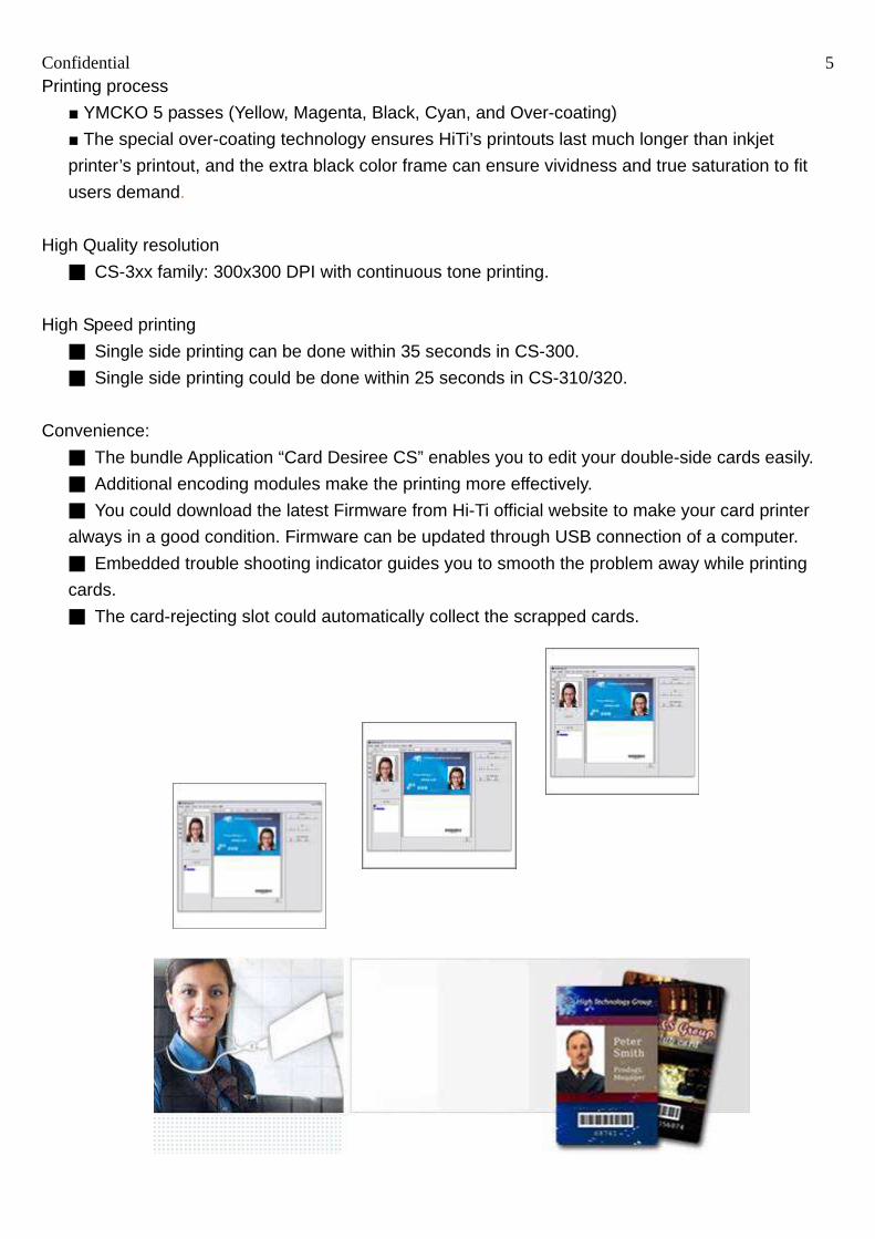
Confidential 5 Printing process
YMCKO 5 passes (Yellow, Magenta, Black, Cyan, and Over-coating)
The special over-coating technology ensures HiTi’s printouts last much longer than inkjet
printer’s printout, and the extra black color frame can ensure vividness and true saturation to fit
users demand.
High Quality resolution
CS-3xx family: 300x300 DPI with continuous tone printing.
High Speed printing
Single side printing can be done within 35 seconds in CS-300.
Single side printing could be done within 25 seconds in CS-310/320.
Convenience:
The bundle Application “Card Desiree CS” enables you to edit your double-side cards easily.
Additional encoding modules make the printing more effectively.
You could download the latest Firmware from Hi-Ti official website to make your card printer
always in a good condition. Firmware can be updated through USB connection of a computer.
Embedded trouble shooting indicator guides you to smooth the problem away while printing
cards.
The card-rejecting slot could automatically collect the scrapped cards.

Confidential 6
Chapter 2. Innovative New Design Comparison of the new designed card printer and original photo printers:
2-1. Difference between CS300 and CS310/320 CS-300 CS-310/CS-320 Function
Motor ADF_Motor,Flip__motor1 (8.3Ω)
Cam_TPH_Motor (8.3Ω)
Cam_Pinch_Motor (8.3Ω)
RBN_Motor (8.3Ω)
ADF_Motor, Flip__motor1 (8.3Ω to 2.8Ω)
Cam_TPH_Motor (8.3Ω to 2.8Ω)
Cam_Pinch_Motor (8.3Ω to 2.8Ω)
RBN_Motor (8.3 Ω to 4Ω)
Drive the motor faster to shorten
printing time by use small Ω motors.
LCM English/Spanish available English/Spanish/Simplified. Chinese
More language will be supported soon.
Multi-language
TPH Certified engineer adjustable
(47.C0120 001)
User-friendly adjustable (47.C0121.001)
New module will also be workable
in CS-300 after replacing compatible
module- P/N: 47.C0106.001.
Main
Board
45.C0101.032 45.C02R1.022 New MB to enhance the motor
driving.
2-2. The new user-friendly adjustable TPH module.
G1 module, TPH is only recommended to be adjusted by qualified technician. Could be upgrade to G2 by replacing whole assembly. G2 module, TPH is friendly easy adjustable by end-user.
Confidential 7
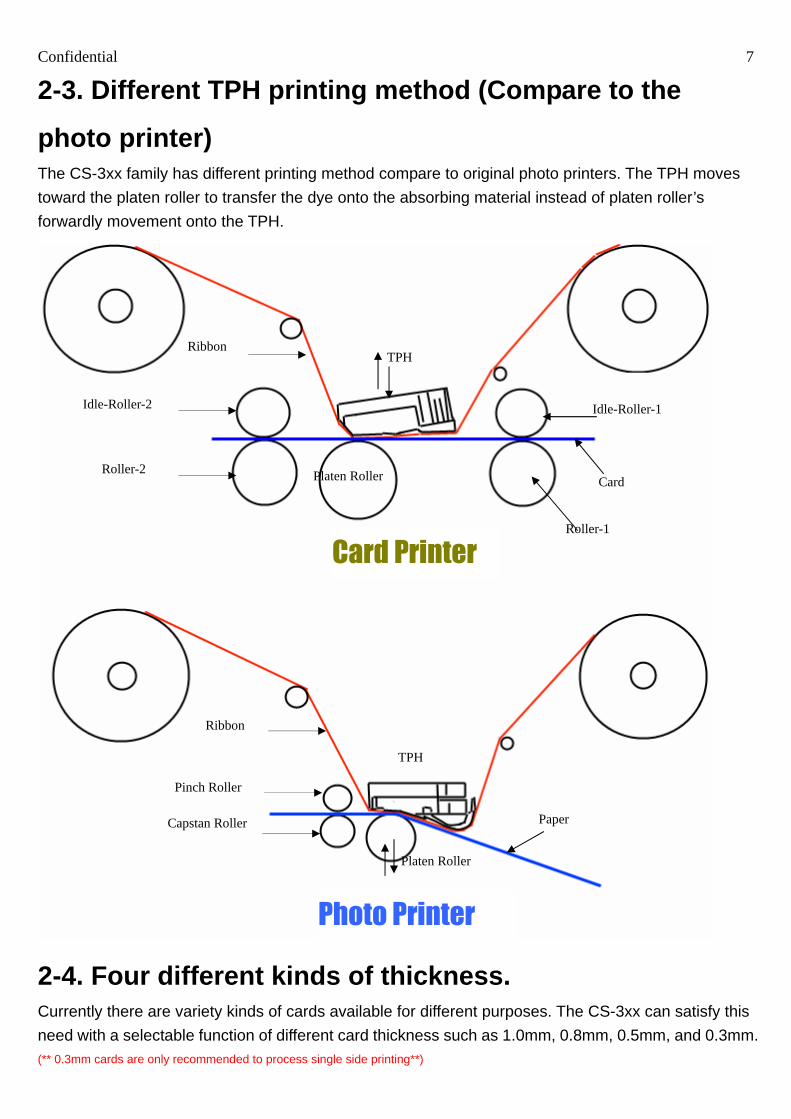
2-3. Different TPH printing method (Compare to the
photo printer) The CS-3xx family has different printing method compare to original photo printers. The TPH moves
toward the platen roller to transfer the dye onto the absorbing material instead of platen roller’s
forwardly movement onto the TPH.
2-4. Four different kinds of thickness. Currently there are variety kinds of cards available for different purposes. The CS-3xx can satisfy this
need with a selectable function of different card thickness such as 1.0mm, 0.8mm, 0.5mm, and 0.3mm. (** 0.3mm cards are only recommended to process single side printing**)
Idle-Roller-2
Roller-2
Ribbon TPH
Idle-Roller-1
Card
Roller-1
Platen Roller
Card Printer
Photo Printer
Platen Roller
Capstan Roller
Pinch Roller
TPH
Ribbon
Paper

Confidential 8
2-5. Double-side printing mechanism (only in CS-300/CS-320) The “flip-base” mechanism enables the CS-3xx to make excellent double-side printouts in one cycle
automatically. There is a crankshaft that drives the flip-base into 3 positions. The “Up-side lock”
controls the upper side printing, and when this device rotates to “Bottom-side lock” it starts to print the
other side. The 3rd position, “Error-exit lock” functions when Smart IC encoding error happens. The
printer will reject the failed card automatically.

Confidential 9
2-6. The new ADF apparatus The “ADF Limit” device offers a different height of gap to feed 0.3mm, 0.5mm, 0.8mm or 1.0mm PVC
cards. The “Card Weight” device ensures the function of card feeding, even one card loaded inside
only.
Up Side
Bottom Side Error Exit

Confidential 10
2-7. Enhanced cleaning roller The enhanced cleaning roller uses high durable material that could remove dust particles from
printouts, also it’s “easy-to-remove" design allows the user to clean this roller easily and frequently.
NOTE:
(1) Do NOT install the cleaning roller during transportation.
(2) The double-side printing will be failed if the cleaning roller is not installed. (Install the cleaning
roller before printing.)
(3) It is suggested to clean the cleaning roller after per 400 prints.
2-8. Subsequent Printing Support
The lamination function of Hi-Ti card printers can do bunch
printing to make additional effects such as to plate cards with
gold, silver and hologram to have a better visual or physical
identification.
Confidential 11
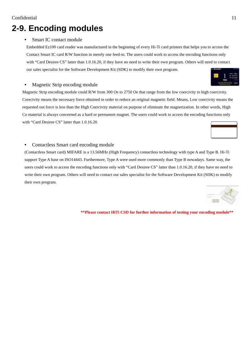
2-9. Encoding modules • Smart IC contact module
Embedded Ez100 card reader was manufactured in the beginning of every Hi-Ti card printers that helps you to access the
Contact Smart IC card R/W function in merely one feed-in. The users could work to access the encoding functions only
with “Card Desiree CS” latter than 1.0.16.20, if they have no need to write their own program. Others will need to contact
our sales specialist for the Software Development Kit (SDK) to modify their own program.
• Magnetic Strip encoding module
Magnetic Strip encoding module could R/W from 300 Oe to 2750 Oe that range from the low coercivity to high coercivity.
Corecivity means the necessary force obtained in order to reduce an original magnetic field. Means, Low coercivity means the
requested out force is less than the High Coercivity material on purpose of eliminate the magnetization. In other words, High
Co material is always concerned as a hard or permanent magnet. The users could work to access the encoding functions only
with “Card Desiree CS” latter than 1.0.16.20.
• Contactless Smart card encoding module
(Contactless Smart card) MIFARE is a 13.56MHz (High Frequency) contactless technology with type A and Type B. Hi-Ti
support Type A base on ISO14443. Furthermore, Type A were used more commonly than Type B nowadays. Same way, the
users could work to access the encoding functions only with “Card Desiree CS” latter than 1.0.16.20, if they have no need to
write their own program. Others will need to contact our sales specialist for the Software Development Kit (SDK) to modify
their own program.
**Please contact HiTi CSD for further information of testing your encoding module**

Confidential 12
Chapter 3. Operating Theory 3-1 Dye Diffusion Thermal Transfer (D2T2)
Dye Diffusion Thermal Transfer (D2T2) , we adopt the world’s leading photo printing technology in
card printing processes, CS-3xx family all use a thermal printing head (TPH) to sequentially heat 5
ribbon panels that are coated with yellow, magenta, cyan, black and over-coating layer. The heat
process turns the dye into gas that diffuses into a thin receiving layer on top of the card. An overcoat is
then layered down on top of the card to protect the color against water and ultraviolet rays and to
prevent it from fading.
Compared with some other photo-capable printing technologies, such as Thermal Autochrome
(Fujifilm), Variable Dot (Fujicopian) and Inkjet (Canon, Epson and HP), Dye Diffusion Thermal Transfer
creates the most realistic photo quality. To the naked eye it is indistinguishable from photographic
prints. Its continuous-tone printing produces 256 color gradation levels in each pixel independently
while other technologies, like Variable Dot and Inkjet, have to make different dot sizes to increase the
resolution in half tone to achieve similar effects.
The Thermal Print Head (TPH) sequentially
heats three ribbon panels that are coated with
dye in yellow, magenta, cyan and black. The
heat process turns the dye into gas that
diffuses into a thin receiving layer on top of the
paper. An overcoat is then layered down on top
of the paper to protect the color against water
and ultraviolet and to prevent it from fading.
Paper
TPH
Ribbon
Dye
Heat
Card

Confidential 13
3-2 Hardware
Thermal Print Head (TPH) is the key component for D2T2 printer, like the inkjet printing head for inkjet printer.
Thermal Print Head (TPH)
Heating Element
Driver IC PCB

Confidential 14
Main Board & ASIC Note: Main Board = Mother board; ASIC = HiTi CPU
The ASIC is an IC (Integrated Chip) located on the Main Board. This ASIC was designed by the HiTi R&D department and features an 8032 MCU. The ASIC drives the USB controller, controls the embedded SDRAM, MCU I/F, USB I/F, memory I/F, and GIO interface. There are two sets of VR (Variable Resistance) on the main board that are used to adjust the voltage of the ribbon sensor. (More details located in the VR adjustment section).
Power Board It contains a universal AC input, DC +25V output. The VR (variable resistance) on the power board is used to adjust the voltage of the TPH. This controls the color density of the printout.

Confidential 15
ADF Motor
Controls the rollers inside the ADF Module to feed cards into the chassis.
Flip Motor-1
Moves the rollers to feed cards into the flip-flop device.
Flip Motor-2
Turns the flip-flop system to each of the position during feeding, encoding and printing.
Cam Pinch Motor
Controls the position of the chip encoder, pinch roller and ribbon rewind.
Cam TPH Motor
Controls the position of TPH and pinch roller to start the dye diffusion thermal transfer during printing.
Ribbon Motor
Winds the ribbon to accurate printing position.
Platen Motor
Moves card while printing is in progress.

Confidential 16
Status/Trouble Shooting Indicator:
The indicator shows the status of CS-3xx for better cleaning function and easy trouble shooting
guidance.
The Basic Flow of the indicator
To put the cleaning card and follow the instructionsClean ProcessingCleaning Mode
To change a languageLanguage
To enable/Disable the buzzer for error occurredBuzzer SEL
To select a ADF sensor typeADF Sensor SEL
To Enable/Disable the card out sensorCard Out SNR
Ribbon sensor selection (Ch1/Ch2)Ribbon CH1
With/without an RF card R/W module (Yes/No)RF Card R/W
With/without a magnetic card R/W module (Yes/No)Magnetic Card R/W
With/without an IC card R/W module (Yes/No)IC Card R/W
Indicates the firmware versionFW version
Indicates the model nameModel Name
Indicates the card thickness setCard Type
Indicates the ribbon type installedRibbon Type
Device Info
DescriptionSub-menuMenu

Confidential 17
Ribbon LED/Ribbon Sensor
Introduction:
The LED/Ribbon Sensors used on CS-3xx family are
penetration type. These Ribbon LED and Ribbon
Sensor enable the printer to detect each definite color
of the ribbon.
The new design, double set of Ribbon LEDs and
Ribbon sensors, is more accurate and reliable than
ever.
Operation Theory:
The previous technology used to detect ribbon colors
is for the beam to penetrate through the ribbon onto
the sensors with different intensity of light and these High (Y, O), Low (M, C) signals can be recognized
by the ASIC.
In CS-3xx, the way to determine color frame of the ribbon is by using two sets of LED/Sensor instead
of one. Due to differences of LED colors, the ribbon sensor detects different high/ low value with
magenta color.
This printer also detects the color of ribbon frame while printing the previous frame. This means when
it’s printing Yellow frame, its actually detecting Magenta fame at the time.

Confidential 18
The anatomy of ribbon searching:
CH1
CH2

Confidential 19
Ribbon cassette sensor:
The “Ribbon count sensor” reads the chip of the ribbon cassette and shows how many prints are left in
your YMCKO or K ribbon.
Cover Sensor:
The cover sensor could identify the cover is open or not. (The twin design can make sure the door is
completely closed.)

Confidential 20
Leading Edge Sensor and Jam Sensor:
The purpose of leading edge (LE) sensor and jam sensor is
to detect the status of the card.
The status of JAM sensor will be “on” when it detects the card.
The Sensor will be “off” when it does not detect any card.
The LE sensor is the penetration sensor. It detects the card
when the card blocks the penetration of light (status is “on”
now).
The transmit direction of the card is controlled by the bearings .
Flip SNR = Senses the card from the ADF Module and also the cards
out of Flipper.
LE & Jam SNR = Locates the position of the exact beginning line
meanwhile measuring the card length. Detecting Card Jam.
JAM SENSOR
LE SENSOR

Confidential 21
Cam Sensor:
Depend on the printer’s status; the positions of the platen roller and the pinch roller stay different. The
Cam controls the movement of the platen roller between these positions, and Cam sensor detects &
sends information back to the firmware. The difference of printing positions is as shown below:
These 4 Cam Sensors are both reflective type.
B. Cam_Pinch sensor: Senses the position of smart chip encoder.
A. Cam_TPH Sensor: Senses the position of TPH.
C. Flip_Cam_Lock sensor: Senses the position of flipper.
D. Flip_Cam_Rotter Sensor: Senses the position of flipper.
A
B
C
D

Confidential 22
Fan:
The Fan reduces the temperature of the TPH (Thermal Print Head). It only starts to work when the
TPH reaches certain degree.

Confidential 23
Chapter 4. Disassembly & Assembly 4-1 Safety Instructions • Read these instructions carefully. Save these instructions for future reference.
• Follow all warnings and instructions marked on the printer.
• Unplug the printer from the wall outlet before disassembly.
• Do not place the printer on an unstable cart, stand, or table. The printer may get damaged by a fall.
• Openings in the chassis and the bottom are provided for ventilation purposes and to ensure
reliable operation of the printer by protecting it form overheating: these openings must not be blocked
or covered.
• Placing the printer on a bed, sofa, rug, or other similar, not firm surfaces may block the openings.
The printer should never be placed near or over a radiator or heat register, proper ventilation and
cooling must be provided at all times.
• The printer should only be operated with the type of power indicated on the marking label. If you
are not sure of the type of power available in your area, consult your dealer or local power company.
• If an extension cord is used with this product, make sure that the total ampere rating of the
equipment plugged into the extension cord does not exceed the extension cord ampere rating. Also,
make sure that the total rating of all products plugged into the wall outlet does not exceed the fuse
rating.

Confidential 24
4-2 Tools
Screwdriver – minus
Tweezer IC Clamp
Wire Cutter
Screwdriver – plus

Confidential 25
4-3 Do not disassemble These Parts HiTi strictly prohibits anyone to disassemble the TPH (Thermal Print Head) and the Bracket-idle. Both parts
need to be calibrated by a specific calibration device and cannot be repaired on site.
Bracket Idle

Confidential 26
4-4 Disassembly
4-4-1 The case of card printer & chassis
Maintenance Parts Replacement Procedures
Parts Name The case of card printer & chassis Parts No.
Tools Screwdriver Procedure No. 1
Appearance view of CS-300
Open the ribbon door with indicated direction.

Confidential 27
Open the ribbon door.
Please put a protection sheet to prevent the screws from falling into the chassis.
Unscrew 4 screws that hold the upper cover.
(PS_ID_DOOR_F_RAPID_C1 56.C0104.012)

Confidential 28 Slightly bend the “Sub Cover” and remove it. (PS_ID_DOOR_B_RAPID_C1 56.C0103.021)
The “Upper Cover” and the “Sub cover”

Confidential 29 There are totally 16 screws on both side need to be removed before separate the ADF and the
Chassis
Also loose these 4 screws to separate the ADF from the chassis.

Confidential 30 Turn the printer back to the upper position and remove the ADF_Cover
(PS_ID_ADF_TOP_RAPID_C1 56.C0129.012)
The ADF Module of CS-3xx (ADF_MODULE_RAPID 47.C0201.002)

Confidential 31 Unscrew these 2 screws, and unplug the “ ADF” to separate the ADF from the Chassis
The isolated ADF module
ADF Connector

Confidential 32 After remove the “ADF Cover”, we could take out the “Chassis Cover”
(PS_ID_COVER_U_RAPID_C1, 56.C0140.061)
Remember to free the connector of the indicator.

Confidential 33 There are totally 6 screws need to be loosen before separating the chassis from the case back.
The rough positions are shown below.
The accurate position of upper 3 screws

Confidential 34 The accurate positions of lower 3 screws

Confidential 35 Lift the chassis up and loose the connectors of “USB module”, “ Card Low Sensor”, ”Jam Eject
Sensor ”, “Door Drawer Sensor”, “24V DC Sensor”, “35V DC Sensor”.
Chassis
35V DC
24V DC
USB Module Card Low Door Drawer Jam Eject

Confidential 36
4-4-2 Main Board
Maintenance Parts Replacement Procedures
Parts Name MAIN BD CS310/320 M31 ROHS Parts No. 45.C02R1.024
Tools Screwdriver Procedure No. 2
Remove ” The case of card printer & chassis”, according to Procedure No. 1
Unplug all the connectors and loose these 4 screws to disassemble the Main Board from
Chassis.
Now, we can take out the Main Board.

Confidential 37
4-4-3 Motors There are 6 motors on the Chassis.
Flip Motor 1 MTR PM 7.5 2.8OHM BIP CS310 ROHS 17.MCC02.BM1
Flip Motor 2 MTR PM7.5 8.3-OHM BIP LF CS-300 17.MHC01.BN2
Cam-Pinch Motor MTR PM 7.5 2.8OHM BIP CS310 ROHS 17.MCC02.BM1
Cam-TPH Motor MTR PM 7.5 2.8OHM BIP CS310 ROHS 17.MCC02.BM1
Ribbon Motor MTR RIB PM 7.5 4OHM BIP CS310 ROHS 17.MBC02.BM1
Platen Motor MTR HB 1.8 1.65V/1.84A BIP CS-310 ROHS 17.MAC02.BT1

Confidential 38

Confidential 39
4-4-3-1 Flip Motor 1” & “Flip Motor 2
Maintenance Parts Replacement Procedures
Parts Name MTR PM 7.5 2.8OHM BIP CS310 ROHS
MTR PM7.5 8.3-OHM BIP LF CS-300
Parts No. 17.MCC02.BM1
17.MHC01.BN2
Tools Screwdriver Procedure No. 3
Remove” The case of card printer & chassis” and “Main Board”, according to Procedure No. 1
and 2
Loose these 4 screws to take out both “Flip Motor 1” & “Flip Motor 2”
Confidential 40
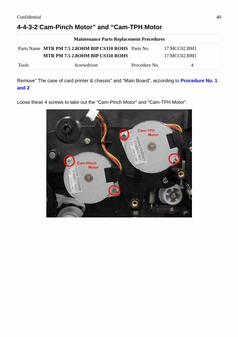
4-4-3-2 Cam-Pinch Motor” and “Cam-TPH Motor
Maintenance Parts Replacement Procedures
Parts Name MTR PM 7.5 2.8OHM BIP CS310 ROHS
MTR PM 7.5 2.8OHM BIP CS310 ROHS
Parts No. 17.MCC02.BM1
17.MCC02.BM1
Tools Screwdriver Procedure No. 4
Remove” The case of card printer & chassis” and “Main Board”, according to Procedure No. 1
and 2
Loose these 4 screws to take out the “Cam-Pinch Motor” and “Cam-TPH Motor”.

Confidential 41
4-4-3-3 Platen Motor
Maintenance Parts Replacement Procedures
Parts Name MTR HB 1.8 1.65V/1.84A BIP CS-310
ROHS
Parts No. 17.MAC02.BT1
Tools Screwdriver Procedure No. 5
Remove” The case of card printer & chassis” and “Main Board”, according to Procedure No. 1
and 2
Unscrew these 4 screws to disassemble “Platen Motor Module”
In order to change the “Platen Motor”, loose these 3 screws as well.

Confidential 42
4-4-3-4 Ribbon Motor
Maintenance Parts Replacement Procedures
Parts Name MTR RIB PM 7.5 4OHM BIP CS310
ROHS
Parts No. 17.MBC02.BM1
Tools Screwdriver Procedure No. 6
Remove” The case of card printer & chassis” and “Main Board”, according to Procedure No. 1
and 2
Loose these 2 screws and then take out the Ribbon Motor.

Confidential 43
4-4-4 LED and Sensor
4-4-4-1 Eject Sensors and USB module
Maintenance Parts Replacement Procedures
Parts Name
WIRE SNR DRAWER_DOOR CS-300 ROHS
WIRE SNR FLIP_JAM_EJECT CS-300
WIRE SNRF FLIP_JAM_CARDFULL CS-300
IF BD USB HUB CS-300 041 ROHS
Parts No. 40.C0120.R05
40.C0105.002
40.C0106.002
45.C01RD.041
Tools Screwdriver Procedure No. 7
Remove” The case of card printer & chassis” and, according to Procedure No. 1 There are 3 sensors and one “USB Module” in the “Bottom Case” of CS-300.
Loose the screws then you could take out these sensors.
CardFull
40.C0120.R05 (WIRE SNR DRAWER_DOOR) 45.C0105.002 (WIRE SNR FLIP_JAM_EJECT )
USB HUB

Confidential 44
Unscrew these 2 screws and unplug the connector to disassemble the “USB HUB”
40.C0106.002 (WIRE SNR FLIP_JAM_CARDFULL) 40.C01RD.041 (IF BD USB HUB)

Confidential 45
4-4-4-2 Ribbon LED
Maintenance Parts Replacement Procedures
Parts Name WIRE LED RIBBON CS-300 ROHS Parts No. 40.C0116.R03
Tools Screwdriver Procedure No. 8
Remove” The case of card printer”, according to Procedure No. 1
Push the heat sink slightly and loose 2 screws to take out ribbon LED.
40.C0116.002 (WIRE LED RIBBON)

Confidential 46
4-4-4-3 Ribbon Sensor
Maintenance Parts Replacement Procedures
Parts Name WIRE SNR RIBBON CS-300 ROHS Parts No. 40.C0117.R02
Tools Screwdriver Procedure No. 9
Remove” The case of card printer”, according to Procedure No. 1
Loose 2 screws to take holder of ribbon sensor out.
Loose 2 screws to take ribbon sensor out.
40.C0117.R02 (WIRE SNR RIBBON)

Confidential 47
4-4-4-4 Flip_LE_Back & Flip_Jam_Back Sensor
Maintenance Parts Replacement Procedures
Parts Name WIRE SNR FLIP_JAM_BACK CS-300
WIRE SNR FLIP_LE_BACK CS-300 Parts No.
40.C0104.002
40.C0108.002
Tools Screwdriver Procedure No. 10
Remove” The case of card printer”, according to Procedure No. 1
Loose 3 screws to take Flip Sensor (WIRE SNR FLIP_JAM_BACK) and (WIRE SNR
FLIP_LE_BACK) out.
40.C0104.002 (WIRE SNR
FLIP_JAM_BACK) 40.C0108.002 (WIRE SNR
FLIP_LE_BACK)

Confidential 48
4-4-4-5 Flip_LE_Front & Flip_LE_Front Sensor
Maintenance Parts Replacement Procedures
Parts Name WIRE SNR FLIP_JAM_FRONT CS-300
WIRE SNR FLIP_LE_FRONT CS-300 Parts No.
40.C0103.002
40.C0107.002
Tools Screwdriver Procedure No. 11
Remove” The case of card printer and chassis”, according to Procedure No. 1
Open the Cleaning Module Cover and loose 2 screws to take Flip Sensor (WIRE SNR
FLIP_JAM_FRONT) out.
Loose 3 screws to take Flip Sensor 2 (WIRE SNR FLIP_LE_FRONT) out.
40.C0103.002 (WIRE SNR
FLIP_JAM_FRONT)

Confidential 49
40.C0107.002 (WIRE SNR FLIP_LE_FRONT)

Confidential 50
4-4-4-6 LE_Back & Jam_Back Sensor
Maintenance Parts Replacement Procedures
Parts Name WIRE SNR LE_BACK CS-300 ROHS
WIRE MB TO JAM_B BD CS-300 Parts No.
40.C0111.003 40.C0124.002
Tools Screwdriver Procedure No. 12
Remove” The case of card printer and chassis”, according to Procedure No. 1
Loose 4 screws to take WIRE SNR LE_BACK and WIRE MB TO JAM_B BD out.
40.C0111.003 (WIRE SNR
LE_BACK)
40.C0124.002 (WIRE MB
TO JAM_B BD)

Confidential 51
4-4-4-7 LE_TPH Sensor
Maintenance Parts Replacement Procedures
Parts Name WIRE SNR LE_TPH CS-300 ROHS Parts No. 40.C0112.003
Tools Screwdriver Procedure No. 13
Remove” The case of card printer and chassis”, according to Procedure No. 1
Loose a screw to take Edge Sensor 3 (WIRE SNR LE_TPH) out.
40.C0112.003 (WIRE SNR LE_TPH)
4-4-4-8 Jam_TPH Sensor
Maintenance Parts Replacement Procedures
Parts Name WIRE SNR JAM_TPH CS-300 Parts No. 40.C0109.003
Tools Screwdriver Procedure No. 14
Remove” The case of card printer and chassis”, according to Procedure No. 1

Confidential 52 Loose 1 screw.
Push roller to another side. (Making sensor free to move.)

Confidential 53 Take sensor out.
40.C0109.003 (WIRE SNR JAM_TPH)
4-4-4-9 LE 4, 5 (LE_Front & Jam_Front Sensor)
Maintenance Parts Replacement Procedures
Parts Name WIRE SNR LE_FRONT CS-300
WIRE MB TO JAM_FBD CS-300 Parts No.
40.C0110.003 40.C0123.002
Tools Screwdriver Procedure No. 15
Remove” The case of card printer and chassis”, according to Procedure No. 1
Take roller and frame_platen_motor out first then you can take LE Sensor out.

Confidential 54
40.C0110.003 (WIRE SNR LE_FRONT)
Loose some screws to take JAM sensor out.

Confidential 55
40.C0123.002 (WIRE MB TO JAM_F BD)
4-4-4-10 Sensor_CAM_Pinch & Sensor_CAM_TPH
Maintenance Parts Replacement Procedures
Parts Name WIRE SNR CAM_TPH CS-300
WIRE SNR CAM_PINCH CS-300 Parts No.
40.C0114.002 40.C0115.002
Tools Screwdriver Procedure No. 16
Remove” The case of card printer & chassis” and “Main Board”, according to Procedure No. 1
and 2
40.C0115.002 (WIRE SNR CAM_PINCH)
40.C0114.002 (WIRE SNR CAM_TPH)

Confidential 56
4-4-4-11 Smart Card Module BD
Maintenance Parts Replacement Procedures
Parts Name SNR BD SC RIBBON CS-300 M21 ROHS Parts No. 45.C01R8.M21
Tools Screwdriver Procedure No. 17
Remove” The case of card printer & chassis” and “Main Board”, according to Procedure No. 1
and 2
Take out the Motor frame; there are 2 nuts which hold 2 screws on sensor as below. Use nut
wrench to hold on the nut.

Confidential 57
Screw off 2 screws which hold the sensor, then take the sensor out.
45.C01R8.M21 (SNR BD SC RIBBON CS-300 M21 ROHS)
Confidential 58
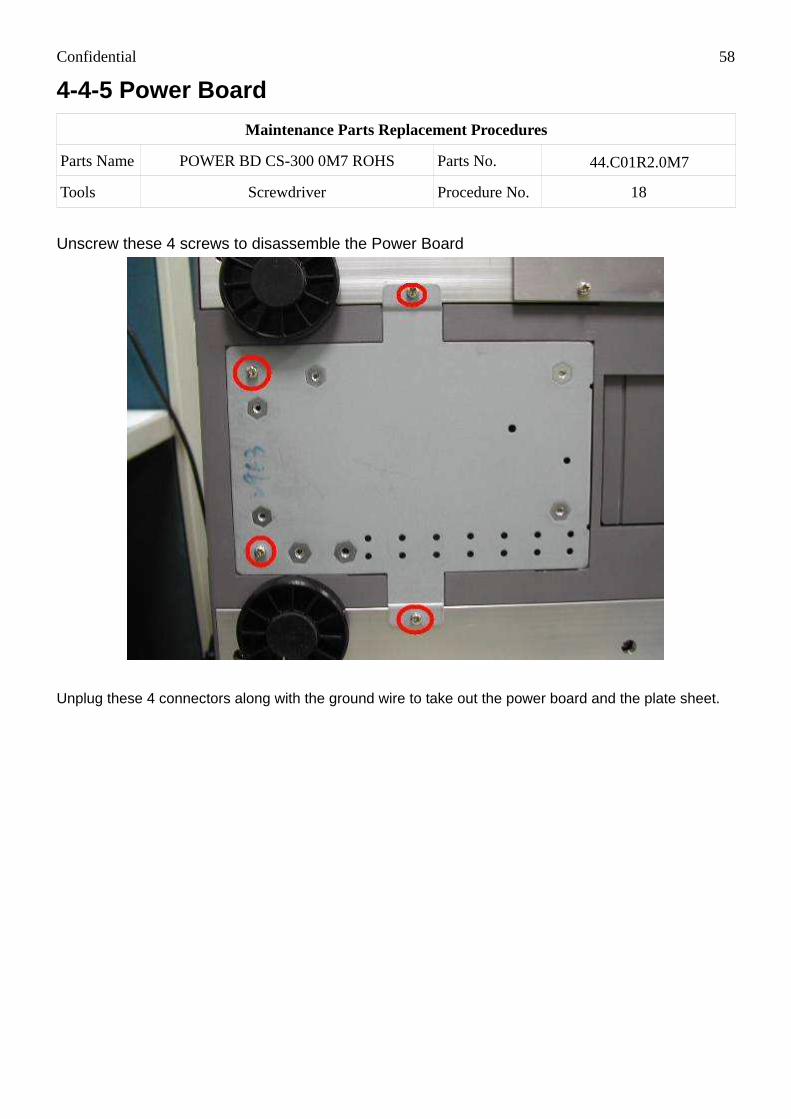
4-4-5 Power Board
Maintenance Parts Replacement Procedures
Parts Name POWER BD CS-300 0M7 ROHS Parts No. 44.C01R2.0M7
Tools Screwdriver Procedure No. 18
Unscrew these 4 screws to disassemble the Power Board
Unplug these 4 connectors along with the ground wire to take out the power board and the plate sheet.

Confidential 59
Unscrew these 4 screws to separate the plate from the power board
44.C01R2.0M7(POWER BD CS-300 0M7 ROHS)

Confidential 60
4-4-6 ADF Module
Maintenance Parts Replacement Procedures
Parts Name
IF BD ADF CS-310 011 ROHS
MTR ADF PM 7.5 2.8OHM BIP CS310
ROHS
Parts No. 45.C02RA.011
17.MEC02.BM1
Tools Screwdriver Procedure No. 19
Loose these 4 screws to take out the ADF control card

Confidential 61
45.C02RA.011 (IF BD ADF CS-310 011 ROHS)
Remove the 2 screws on the other side of the ADF module:

Confidential 62
17.MEC02.BM1 (MTR ADF PM 7.5 2.8OHM BIP CS310 ROHS)
As you flip the ADF module to the upside position, you can see the ADF motor.

Confidential 63
4-4-7 The Status/Trouble Shooting Indicator
Maintenance Parts Replacement Procedures
Parts Name LCD PANEL BD CS-310 011 ROHS Parts No. 45.C02RB.011
Tools Screwdriver Procedure No. 20
Remove” The case of card printer & chassis”, according to Procedure No. 1
Loose these 4 screws to separate the “LCD Panel”, “Indicator PCB”
The detail of the indicator

Confidential 64
It’s important to have these 4 buttons to be accurate.
45.C02RB.011(LCD PANEL BD CS-310 011 ROHS)
Note:
1) When assemble a new LCD module onto a case, make sure 2 positioning pins are accurately
fit into the holds of case.
2) When screw, first please do point 1 and then fix point 2

Confidential 65

Confidential 66
4-4-8 TPH Linkage
Maintenance Parts Replacement Procedures
Parts Name LINKAGE MODULE Parts No. 47.C0202.001
Tools Screwdriver Procedure No. 21
Remove” The case of card printer & chassis”, according to Procedure No. 1
Parts that connects the Remove the C-ring & the gear shown below

Confidential 67 First remove the E-Ring at both sides that holds the crank that connects Linkage with the
Chassis:
Unplug connectors.

Confidential 68 Unscrew the screw that holds the crank to the linkage
Pull out the crank and use a screwdriver to support the linkage from falling off.

Confidential 69 There is a spring which can bounce off easily without caution
Carefully cut the binders so that you can unplug the cables.

Confidential 70 The Linkage of CS-300
47.C0202.001(LINKAGE MODULE)
There is also a dust dustproof cover that can be removed from the linkage:

Confidential 71

Confidential 72
4-5 Assembly
4-5-1 Card Thinness Parameter Set the inner parameter to the top position.
Move the outer parameter to 0.8mm and hold it.
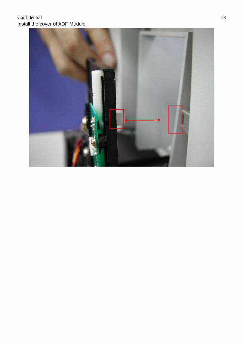
Confidential 73 Install the cover of ADF Module.

Confidential 74
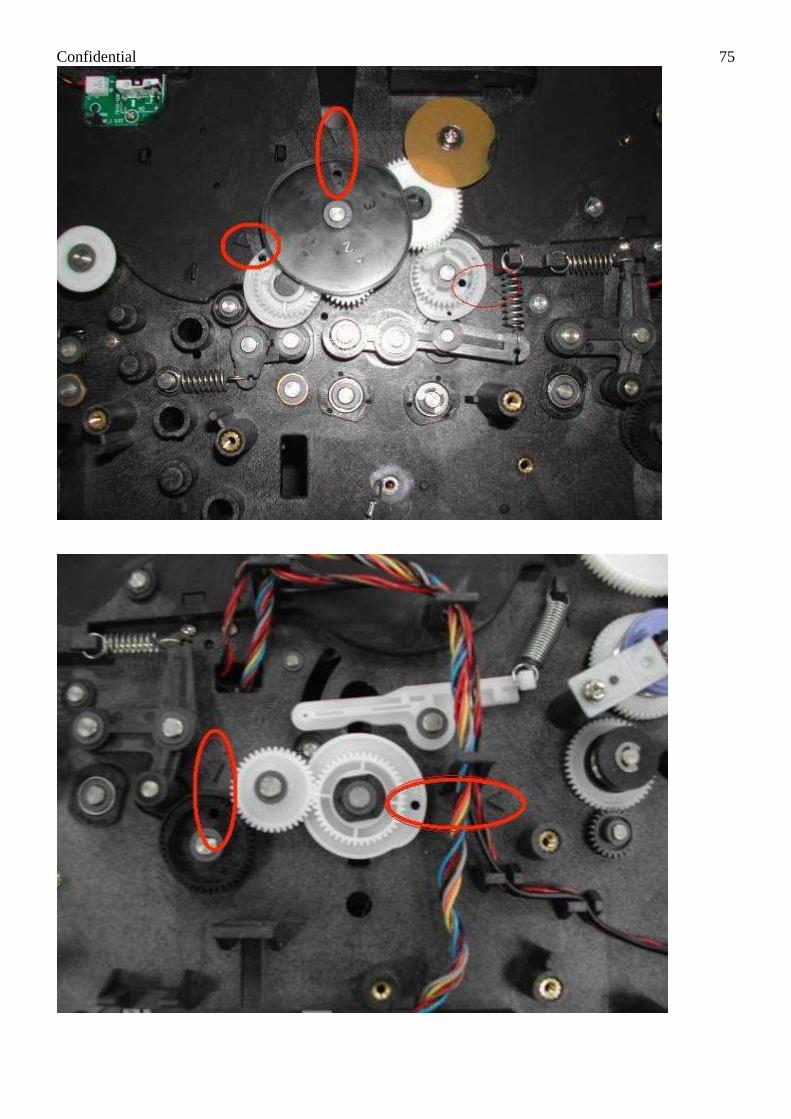
4-5-2. Cam Position There will be a triangle mark pointed to a whole on the gear to set the correct position of these
Cam gears, please follow this procedure as shown below:
Confidential 75

Confidential 76
Chapter 5: Adjustments 5-1 Safety Instructions Read these instructions carefully. Save these instructions for future reference.
Follow all warnings and instructions marked on the product.
Unplug this product from the wall outlet before cleaning.
Do not place this product on an unstable cart, stand, or table. The product may fall, causing
serious damage to the product
Openings in the cabinet and the bottom are provided for ventilation; to ensure reliable
operation of the product and to protect it form overheating, these openings must not be blocked
or covered.
Placing the product on a bed, sofa, rug, or other similar surface and should never block the
openings. These products should never be placed near or over a radiator or heat register, or in a
built-in installation, unless proper ventilation is provided
This product should be operated from the type of power indicated on the marking label. If
you are not sure of the type of power available, consult your dealer or local power company
If an extension cord is used with this product, make sure that the total ampere rating of the
equipment plugged into the extension cord does not exceed the extension cord ampere rating.
Also, make sure that the total rating of all products plugged into the wall outlet do not exceed the
fuse rating
5-2 Contents:
• Tools for VR adjustments
• TPH (G1 Linkage module adjustment)
• TPH (G2 disassembly)
• TPH (G2 assembly)
• Main Board VR adjustment
• Power Board Adjustment

Confidential 77
5-2-1 Tools for VR Adjustments
Screwdriver - plus
Digital Meter
Glue (screw lock)

Confidential 78
5-2-2 TPH Linkage Module Replacement Instruction Fo r
CS300
- When Should You Replace “Linkage Module (47.C0106.001)”?
• Permanent white line (TPH Pixel Fail).
• Permanent black line (TPH Pixel Fail).
• TPH Pixel Fail problem happened to CS-300 that manufactured before 2007/7.
- How To Replace? Parts that connects the Remove the C-ring & the gear shown below
1. First of all, remove the E-ring at both sides that holds the crank that connects linkage to the Chassis.

Confidential 79 2. Unplug connectors.
3. Unscrew the screw that holds the crank to the linkage.
4. Pull out the crank and use a screwdriver to support the linkage from falling off.

Confidential 80 Here is a spring that can bounce off easily without caution
Carefully cut the binders so that you can unplug the cables.
The Linkage of CS-300

Confidential 81 Linkage to the chassis:

Confidential 82
5-2-3TPH Replacement Instruction .
Disassembly of Print Head (47.C0121.001)
Step 1. Refer to the instruction of print head disassembly.
Step 2. Remove 2 screws.

Confidential 83 Step 3. Remove connector then take the print head out.

Confidential 84 Assembly of Print Head (47.C0121.001).
Step 1. Connect connector and screw print head to linkage.
Step 2. Go to 'Control Panel/ Printers and Faxes/ HiTi CS-320/310/ Printing Preferences'.
Step 3. Go to 'Tools/ Maintenance/ Print Head Replacement'.

Confidential 85
Step 4. Input the serial number of new print head to continue the warranty of print head.

Confidential 86 Step 5. Print a calibration chart out then adjust the printing area. Make A line and B line printed inside
the card then ‘Apply’ it to complete the replacement of new print head.

Confidential 87 Note: Copper cushions can be used to align the output performance for getting better uniformity.

Confidential 88
5-2-4 Main Board VR Adjustment
- When Should You Ajudst Main Board VR? 1. When you meet “Card Out” problem, and both Ribbon CH1 and CH2 can't work.
2. When you change Main Board.
3. When you change Ribbon LED.
4. When you change Ribbon Sensor.
5. When you change TPH Linkage.
- How to Adjust? 1. Please connect printer to PC then run HTools.exe. (with version 3.1.0 or later)
2. Please power on the printer then take ribbon cartridge out, and then close ribbon door.
3. Please click “Request value” to make ribbon LEDs on.
4. Please adjust Main Board VR- “R1” (Red LED of the first set), and make it close to 230 (Never over
235).

Confidential 89
5. Please adjust Main Board VR- “G1” (Green LED of the first set), and make it close to 230 (Never over
235).
6. Please adjust Main Board VR- “R2” (Red LED of the second set), and make it close to 230 (Never over
235).

Confidential 90 7. Please adjust Main Board VR- “G2” (Green LED of the second set), and make it close to 230 (Never
over 235).
8. Please click “Calibrate” to enable auto-calibration function for correct ribbon searching.
9. Please insert ribbon cartridge. Make Yellow frame exposed individually between ribbon LEDs and
sensors to request calibration values. Click “Reuqest value” to check if they are all in our specifications.

Confidential 91
Yellow frame exposed between ribbon LEDs and sensors.
NOTE 1:
(1) R1= 218, means ribbon sensor receives HIGH penetrating light from Red LED (the 1st set) and Yellow
Frame.
(2) G1= 217, means ribbon sensor receives HIGH penetrating light from Green LED (the 1st set) and
Yellow Frame.
(3) R2= 217, means ribbon sensor receives HIGH penetrating light from Red LED (the 2nd set) and Yellow
Frame.
(4) G2= 218, means ribbon sensor receives HIGH penetrating light from Green LED (the 2nd set) and
Yellow Frame.
NOTE 2:
(1) The 1st value is digital voltage value you have just adjusted to Main Board VR- R1, G1, R2 and G2
(around 230).

Confidential 92 (2) The 2nd value is a half of the 1st value. This is for a judgment standard of HIGH or LOW penetrating
light (=digital voltage value).
(3) The 3rd value is digital voltage value which is made by ribbon LEDs and sensors. Above the 2nd value
means HIGH, and below the 2nd value means LOW. The 3rd value MUST have obvious difference compared
to the 2nd value, or the ribbon searching function of printer may fail soon.
10. Please make Magenta frame exposed individually between ribbon LEDs and sensors to request
calibration values, and check if it is in our specifications.

Confidential 93
Magenta frame exposed between ribbon LEDs and sensors.
NOTE:
(1) R1= 211, means ribbon sensor receives HIGH penetrating light from Red LED (the 1st set) and Magenta
Frame.
(2) G1= 5, means ribbon sensor receives LOW penetrating light from Green LED (the 1st set) and Magenta
Frame.
(3) R2= 207, means ribbon sensor receives HIGH penetrating light from Red LED (the 2nd set) and
Magenta Frame.
(4) G2= 4, means ribbon sensor receives LOW penetrating light from Green LED (the 2nd set) and Magenta
Frame.
11. Please make Cyan frame exposed individually between ribbon LEDs and sensors to request calibration
values, and check if it is in our specifications.

Confidential 94
Cyan frame exposed between ribbon LEDs and sensors.
NOTE:
(1) R1= 28, means ribbon sensor receives LOW penetrating light from Red LED (the 1st set) and Cyan
Frame.
(2) G1= 42, means ribbon sensor receives LOW penetrating light from Green LED (the 1st set) and Cyan
Frame.
(3) R2= 31, means ribbon sensor receives LOW penetrating light from Red LED (the 2nd set) and Cyan
Frame.
(4) G2= 43, means ribbon sensor receives LOW penetrating light from Green LED (the 2nd set) and Cyan
Frame.
12. After confirming above, please glue Main Board VR- R1, G1, R2 and G2 to ensure all VR will not shift
during transportation and vibration.
Confidential 95
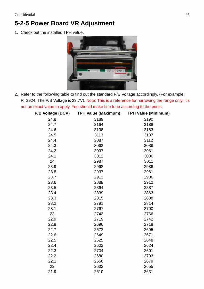
5-2-5 Power Board VR Adjustment 1. Check out the installed TPH value.
2. Refer to the following table to find out the standard P/B Voltage accordingly. (For example:
R=2924. The P/B Voltage is 23.7V). Note: This is a reference for narrowing the range only. It’s
not an exact value to apply. You should make fine tune according to the prints.
P/B Voltage (DCV) TPH Value (Maximum) TPH Value (Mi nimum) 24.8 3189 3190 24.7 3164 3188 24.6 3138 3163 24.5 3113 3137 24.4 3087 3112 24.3 3062 3086 24.2 3037 3061 24.1 3012 3036 24 2987 3011
23.9 2962 2986 23.8 2937 2961 23.7 2913 2936 23.6 2888 2912 23.5 2864 2887 23.4 2839 2863 23.3 2815 2838 23.2 2791 2814 23.1 2767 2790 23 2743 2766
22.9 2719 2742 22.8 2696 2718 22.7 2672 2695 22.6 2649 2671 22.5 2625 2648 22.4 2602 2624 22.3 2704 2601 22.2 2680 2703 22.1 2656 2679 22 2632 2655
21.9 2610 2631
Confidential 96
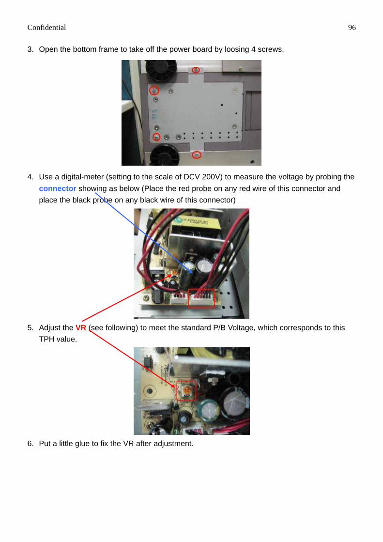
3. Open the bottom frame to take off the power board by loosing 4 screws.
4. Use a digital-meter (setting to the scale of DCV 200V) to measure the voltage by probing the
connector showing as below (Place the red probe on any red wire of this connector and
place the black probe on any black wire of this connector)
5. Adjust the VR (see following) to meet the standard P/B Voltage, which corresponds to this
TPH value.
6. Put a little glue to fix the VR after adjustment.

Confidential 97
Chapter 6: Contact Information
Website: www.hiti.com
Email: [email protected]
Taiwan (Asia) - Headquarters HiTi Digital, Inc. 9F., No.225, Sec. 3, Beixin Rd., Xindian Dist., New Taipei City 231, Taiwan (R.O.C.)
TEL: +886-2-2912-6268
FAX: +886-2-2912-6117, +886-2-2912-6118
Branch (Office) Locations: China 58 QunXing Road One, Suzhou Industrial Park, 215006, China, PRC
TEL: +86-512-67601688 FAX: +86-512-67601186
United States (North America) 727 Brea Canyon Rd. Suite#2,
Walnut, CA 91789, U.S.A.
TEL: +909-974-0099
FAX: +909-974-0011
Netherlands (Europe) Esp 206, 5633 AC, Eindhoven, The Netherlands
TEL: +31-40-256-5166
FAX: +31-40-290-3176
India # 401/402, 4th Floor Siddharth Building -96, Nehru Place, New Delhi- 110019
TEL: +91-11-4180-8191
FAX: +91-11-4180-8193
UAE (Middle East and Africa) Office No. 1608, Indigo Icon Tower, JLT, Dubai - U.A.E.
TEL: +971-4-3674547
FAX: +971-4-3674221
Mexico (South America) Agustin Gonzalez de Cossio No. 1-202 Col Del Valle, C.P. 03100, Mexico, D. F. Mexico
TEL: +52-55-50253671