CS 3 - Athrodax · Prior to implanting a MAGNEZIX® CS 3.2 screw it is necessary to ensure...
20
Intelligent innovations for a better life. CS 3.2 Product information
Transcript of CS 3 - Athrodax · Prior to implanting a MAGNEZIX® CS 3.2 screw it is necessary to ensure...

Intelligent innovations for a better life.
CS 3.2Product information

CAUTION
This product description is not sufficient or adequate to allow immediate
use of the instruments and the implant described. Instruction must be
given by authorized personnel prior to use of these instruments and im-
plants!
Since the implants are designed for single use only, reuse of MAGNEZIX®
implant devices is grossly negligent and can result in an increased risk of
infection and loss in implant stability. In general, re-sterilization alters the
implant’s functionality in an unpredictable way.
In the case of concurrent use of third party implants it must borne in mind
that steel, titanium and cobalt-chromium alloys may not remain in direct
contact with a MAGNEZIX® implant at the intervention site (i.e. no physical
contact of implants).
The image shown on the cover is a CAD image. The actual implant may differ in appearance.

INTRODUCTION 04
THE MATERIAL MAGNEZIX® 04
INTENDED USE 06
INDICATIONS 06
CONTRAINDICATIONS 06
WARNINGS 06
ADVANTAGES AND FEATURES 08
SURGICAL TECHNIQUE 10
PRODUCT OVERVIEW 16
IMPLANTS 16
INSTRUMENTS 17
05 Introduction04 . Syntellix AG
MAGNEZIX® Compression Screw 3.2
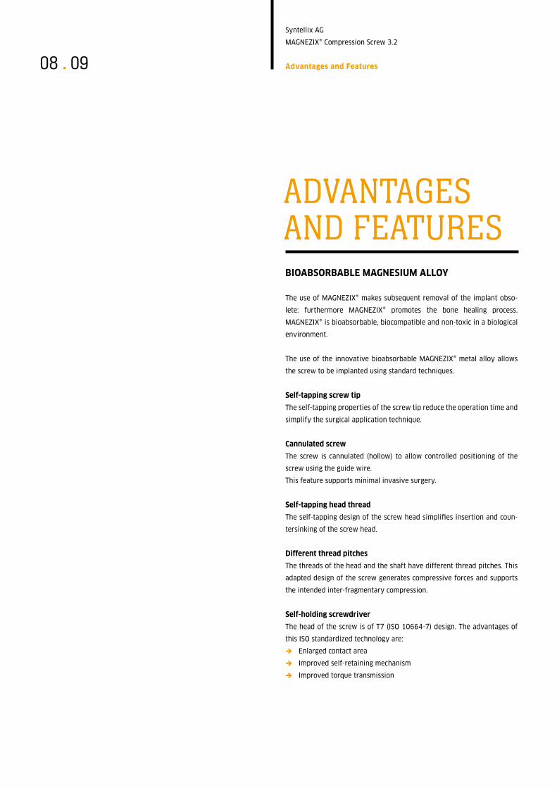
MAGNEZIX®THE MATERIAL MAGNEZIX®
MAGNEZIX® is the name given to the world’s first bioabsorbable implant
material: it is a metallic alloy that has a CE Mark approval for medical
applications within Europe.
MAGNEZIX® is a magnesium-based alloy with the properties of a metal but
which is nonetheless fully absorbable in the body where it is replaced by
body-own tissue. The biomechanical properties of MAGNEZIX® are very
similar to those of human bone. Some studies have also demonstrated
that magnesium alloys have osteoconductive properties.1
Advantages for users and patients
ÎComplete bioabsorption of the implant makes later removal of the
product obsolete.
ÎThe mechanical properties are significantly better than those of
conventional resorbable implants.
ÎThe implant is completely and homogenously transformed into
body-own tissue.
ÎHistological investigations show bone formation at the implant‘s
surface and bone growth into previously bioabsorbed implant sites.
ÎThe use of MAGNEZIX® implants does not lead to so-called „stress
shielding“ (bone degradation) due to bone-like biomechanical
properties.
ÎIn terms of applicability, MAGNEZIX® implants hardly differ from
conventional implants made of steel or titanium. This is ensured by
the adapted design, which takes the material and bioabsorbable
properties into account.
ÎMAGNEZIX® implants are visible radiographically, MR conditional and
do cause marginal artifacts only (please refer to the Instructions for
Use).
1 Revell et al. (2004) The effect of magnesium ions on bone bonding to hydroxyapatite coating on
titaniumalloy implants. Key Eng Mater Vol. 254-256, 447-50.
Liu et al. (1988) Magnesium directly stimulates osteoblast proliferation. J Bone Miner Res (3), 104.
Zreiqat et al. (2002) Mechanisms of magnesium-stimulated adhesion of osteoblastic cells to commonly
used orthopaedic implants. J Biomed Mater Res 62 (2), 175-84.

05 Introduction
Syntellix AG
MAGNEZIX® Compression Screw 3.2
© O
rtho
pädi
sche
Klin
ik d
er M
HH
Figure left:
Histological evaluations in an animal
study verified full and complete trans-
formation of the metallic implant after a
12-month implant period. Studies
demonstrated new bone formation with
direct implant contact and presence of
osteoblasts and osteoclasts.
SAGE Publications Ltd. All rights reserved.
Waizy H, Diekmann J, Weizbauer A et al. (2014) In vivo
study of a biodegradable orthopedic screw
(MgYREZr-alloy) in a rabbit model for up to 12 months.
J Biomater Appl 28 (5), 667-75.

07
Syntellix AG
MAGNEZIX® Compression Screw 3.2
Introduction06 .
INTENDED USE
MAGNEZIX® CS bioabsorbable compression screws serve the purpose of
re-establishing bone continuity after fractures and osteotomies (osteo-
synthesis) as well as for treatment of pseudarthroses (re-osteotomies).
The objective when using the MAGNEZIX® CS device is specifically ana-
tomic retention by way of surgical splinting of assembled bone fractions
after prior repositioning until bony healing. The implants are designed for
single use only.
INDICATIONS
The indications for MAGNEZIX® CS implants are reconstructive procedures
after fractures, malpositions and/or other pathological bone alterations of
the human skeleton. The surgeon must in all cases determine the extent of
the injuries or the bony alterations and the scope of the necessary surgi-
cal intervention and select the appropriate operating procedure and the
appropriate implant. This applies in particular when using bioabsorbable
MAGNEZIX® implants. The surgeon is always responsible for the decision
to use the implant.
According to its respective dimension, MAGNEZIX® CS can be used for
adaption- and exercise-stable fixation of bones and bone fragments in
children, adolescents and adult persons. Relevant medical literature and
guidelines must be observed when determining the dimensions of screws
to be used.
The MAGNEZIX® CS 3 2 is for example suitable for the following:
ÎIntra-articular and extra-articular fractures of small bones and
bony fragments
ÎArthrodeses, osteotomies and pseudarthroses of small bones
and joints
ÎSmall bony avulsions of ligaments and tendons
Including:
ÎCarpalia, metacarpalia, tarsalia and metatarsalia
ÎEpicondylus humeri
ÎProcessus styloideus radii et ulnae
ÎCapitulum and caput radii
ÎHallux-valgus-corrections
CONTRAINDICATIONS
In specific clinical situations the use of MAGNEZIX® implants may be pro-
hibited (absolute contraindication) or use may be planned subject to cer-
tain considerations (relative contraindication).
Absolute contraindications
ÎInsufficient bone substance to anchor the implant
ÎEvidence or suspicion of septic-infectious operating area
ÎKnown allergies and/or known foreign body reactions
ÎApplication in the area of the epiphyseal plates
ÎLoad-stable osteosyntheses
ÎArthrodeses of medium-sized and large joints
ÎUse in the spinal column
Relative contraindications
ÎOptions for conservative treatment
ÎAcute sepsis
ÎOsteoporosis
ÎAlcohol and/or drug misuse
ÎEpilepsy
ÎLimited skin/soft tissue conditions
ÎNon co-operative patient or limited mental state of patient
ÎNo possibility for providing adequate post-operative follow-up
(e.g. temporary load relief)
WARNINGS
In the case of concurrent use of third party implants it must borne in mind
that steel, titanium and cobalt-chromium alloys may not remain in direct
contact with a MAGNEZIX® implant at the intervention site (i.e. no physical
contact of implants).
Since the implants are designed for single use only, reuse of MAGNEZIX®
implant devices is grossly negligent and can result in an increased risk of
infection and loss in implant stability.
In general, re-sterilization alters the implant’s functionality in an unpre-
dictable way.

07
Syntellix AG
MAGNEZIX® Compression Screw 3.2
Introduction
0908 . Syntellix AG
MAGNEZIX® Compression Screw 3.2
Advantages and Features
BIOABSORBABLE MAGNESIUM ALLOY
The use of MAGNEZIX® makes subsequent removal of the implant obso-
lete: furthermore MAGNEZIX® promotes the bone healing process.
MAGNEZIX® is bioabsorbable, biocompatible and non-toxic in a biological
environment.
The use of the innovative bioabsorbable MAGNEZIX® metal alloy allows
the screw to be implanted using standard techniques.
Self-tapping screw tip
The self-tapping properties of the screw tip reduce the operation time and
simplify the surgical application technique.
Cannulated screw
The screw is cannulated (hollow) to allow controlled positioning of the
screw using the guide wire.
This feature supports minimal invasive surgery.
Self-tapping head thread
The self-tapping design of the screw head simplifies insertion and coun-
tersinking of the screw head.
Different thread pitches
The threads of the head and the shaft have different thread pitches. This
adapted design of the screw generates compressive forces and supports
the intended inter-fragmentary compression.
Self-holding screwdriver
The head of the screw is of T7 (ISO 10664-7) design. The advantages of
this ISO standardized technology are:
ÎEnlarged contact area
ÎImproved self-retaining mechanism
ÎImproved torque transmission
ADVANTAGESAND FEATURES

09
Syntellix AG
MAGNEZIX® Compression Screw 3.2
Advantages and Features
ADVANTAGESAND FEATURES

1110 . Syntellix AG
MAGNEZIX® Compression Screw 3.2
Surgical Technique
SURGICAL TECHNIQUESURGICAL TECHNIQUE MAGNEZIX® CS – STEP BY STEP
Prior to implanting a MAGNEZIX® CS 3.2 screw it is necessary to ensure
repositioning and temporary stabilization of the fracture or the osteoto-
my.
Step 1: Positioning the guide wire
Position the guide wire through the double drill guide with fitted drill
guide, if necessary monitor using image intensification, until it is in the
required position.
Important
Avoid excess force when inserting the guide wire. Excess force will bend
the guide wire and may hinder subsequent reaming or insertion of the
screw.
Instruments used:
➀ 9032.033 Double Drill Guide, Ø 3.5/2.5 mm
➁ 9032.034 Drill Guide, Ø 2.5/1.3 mm
➁ 9032.040 Guide Wire Ø 1.2 mm, with trocar tip,
length 150 mm
or
➂ 9032.041 Guide Wire Ø 1.2 mm, with threaded tip,
length 150 mm
Step 2: Determination of screw length
The length of the screw is determined by sliding the measuring device over
the guide wire to the bone. The end of the guide wire, visible in the scale of
the measuring device, indicates the length of the screw to be used (22 mm
in the figure).
Important
Only the original guide wires guarantee correct measurement.
Instruments used
➃ 9032.042 Measuring Device for Guide Wires Ø 1.2 mm,
Guide Wire length 150 mm

11
Syntellix AG
MAGNEZIX® Compression Screw 3.2
Surgical Technique
STEP 1
STEP 2
➀
➂
➁
➃

1312 . Syntellix AG
MAGNEZIX® Compression Screw 3.2
Surgical Technique
Step 3: Pre-drilling
For screws with self-tapping tips, pre-drilling over the desired screw
lengths is mandatory. At this point, the cannulated drill bit is directed by
the underlying guide wire. This facilitates the subsequent tightening of the
screw and prevents the rotation of small bone fragments.
The drill bit calibration allows the drill depth reached to be read at the top
end of the drill guide. The fine ring marks indicate 2 mm steps, the domi-
nant ring marks indicate 10 mm drill steps.
Important
It is crucial to only drill to the tip of the guide wire. Slowly pull the drill bit
out vertically from the double drill guide while slowly turning in a forward
direction so as to leave the guide wire in position.
Instruments used:
➀ 9032.033 Double Drill Guide, Ø 3.5/2.5 mm
➁ 9032.020 Drill Bit Ø 2.5/1.3 mm, cannulated,
length 160/135 mm, for quick coupling
Step 4: Countersinking
In order to simplify insertion of the screw head, the head side of the in-
tended implant position is now reamed using the countersink with the
guide wire still in place.
Important
If the screw is positioned perpendicular to the bone surface, countersink-
ing to the first ring marking (RM 1) is required in order to achieve ade-
quate countersinking of the screw head.
If the screw is positioned at an angle of 45° to the bone surface, counter-
sinking to the second ring marking (RM 2) is required in order to achieve
adequate countersinking of the screw head.
The countersink is pulled vertically out of the drill guide while still slowly
turning in the forward direction so as to leave the guide wire in position.
Instruments used
➀ 9032.033 Double Drill Guide, Ø 3.5/2.5 mm
➂ 9032.021 Countersink Ø 3.5/1.3 mm,
cannulated, for quick coupling

13
Syntellix AG
MAGNEZIX® Compression Screw 3.2
Surgical Technique
STEP 3
STEP 4
RM 1
RM 2
RM 2
0° 45°
➀
➁
➀
➂
0 mm marker
Min. length 10 mm
Max. length 40 mm

1514 . Syntellix AG
MAGNEZIX® Compression Screw 3.2
Surgical Technique
Step 5: Insertion of the screw
This is now followed by the tightening of the MAGNEZIX® Compression
Screw 3.2 over the underlying guide wire in the length previously deter-
mined in step 2.
Important
Take care to ensure that the guide wire was not damaged during steps 1
through 4. A damaged guide wire may result in the MAGNEZIX® Compres-
sion Screw 3.2 to not end up fully turned in. In this case the guide wire
must be removed before insertion of the screw.
Bear in mind that the shaft thread could pull out of the distal bone frag-
ment if the induced compression forces when screwing in the screw are
excessive.
If the selected screw is too short the shaft thread might cross the fracture
or osteotomy gap. If this situation results no compression will be generat-
ed. Therefore, to ensure the correct position of the threaded shaft it is
recommended to check the position using an image intensifier.
If one finds the thread crossing the fracture or osteotomy gap the screw
must be removed and a longer screw has to be selected in order to gener-
ate compression. When doing this and in the case of a hard (dense) bone
situation, it might be necessary to repeat the pre-drilling process as de-
scribed in step 3 to further deepen the pre-drilled pilot hole for the select-
ed screw with an adequate length.
When the screw is in its final position the guide wire is removed.
Instruments used
➀ 6032.108 Screwdriver T8, One-Piece Handle,
Ø 1.3 mm cannulated
9032.033 Double Drill Guide, Ø 3.5/2.5 mm
Optional
6032.208 Screwdriver T8, Multi-Part Handle,
Ø 1.3 mm cannulated

15
Syntellix AG
MAGNEZIX® Compression Screw 3.2
Surgical Technique
STEP 5
➀
1716 . Syntellix AG
MAGNEZIX® Compression Screw 3.2
Product Overview
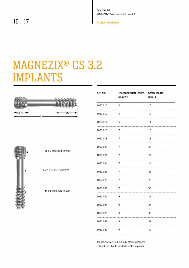
Art No Threaded shaft length Screw length
[mm] SG [mm] L
______________________________________________________________________________
1032.010 4 10
1032.012 5 12
1032.014 5 14
1032.016 7 16
1032.018 7 18
1032.020 7 20
1032.022 7 22
1032.024 7 24
1032.026 7 26
1032.028 7 28
1032.030 7 30
1032.032 9 32
1032.034 9 34
1032.036 9 36
1032.038 9 38
1032.040 9 40
All implants are individually sterile packaged.
It is not possible to re-sterilize the implants.
3.5 mm SG
L
Ø 4.0 mm Head thread
Ø 2.4 mm Shaft diameter
Ø 3.2 mm Shaft thread
MAGNEZIX® CS 3.2 IMPLANTS

17
Syntellix AG
MAGNEZIX® Compression Screw 3.2
Product Overview
Art No Description
______________________________________________________________________________
6032.108 Srcewdriver T8, One-Piece Handle
Ø 1.3 mm cannulated, consisting of:
9099.001 One-Piece Handle for Screwdriver:
9032.015 Screwdriver blade T8
6032.208 Screwdriver T8, Multi-Part Handle
Ø 1.3 mm cannulated, consisting of:
9099.002 Multi-Part Handle for Screwdriver
9032.015 Screwdriver blade T8
9032.020 Drill Bit Ø 2.5/1.3 mm, cannulated,
length 160/135 mm, for quick coupling
9032.021 Countersink Ø 3.5/1.3 mm, cannulated,
for quick coupling
9032.033 Double Drill Guide, Ø 3.5/2.5 mm
9032.034 Drill Guide, Ø 2.5/1.3 mm
9032.040 Guide Wire Ø 1.2 mm, with trocar tip,
length 150 mm (do not reuse)
9032.041 Guide Wire Ø 1.2 mm, with threaded tip,
length 150 mm (do not reuse)
9032.042 Measuring Device, for Guide Wires Ø 1.2 mm,
Guide Wire length 150 mm
9032.050 Cleaning Stylet Ø 1.25 mm,
for Ø 1.3 mm cannulated instruments
Not shown:
8032.001 Sterilizing Tray for MAGNEZIX® CS Ø 3.2 mm,
without contents
8032.002 Lid for Sterilizing Tray, for MAGNEZIX® CS Ø 3.2 mm*The figures are not to scale.
MAGNEZIX® CS 3.2 INSTRUMENTS*

Syntellix AG
MAGNEZIX® Compression Screw 3.2
METALLIC AND BIOABSORBABLE.A MEDICAL SENSATION.MAGNEZIX®

Syntellix AG
MAGNEZIX® Compression Screw 3.2
METALLIC AND BIOABSORBABLE.A MEDICAL SENSATION.MAGNEZIX®
70
32
.00
1.0
05
09
/15
Syntellix AG
Schiffgraben 11
30159 Hannover
Germany
T +49 511 270 413 50
F +49 511 270 413 79
www.syntellix.com
Implants are manufactured in Germany
in cooperation with Königsee Implantate GmbH.
Presented by:
0197