CS 150 - Fall 2005 – Lec. #18: Testing - 1 Testing of Logic Circuits zFault Models zTest...
31
CS 150 - Fall 2005 – Lec. #18: Testing - 1 Testing of Logic Circuits Fault Models Test Generation and Coverage Fault Detection Design for Test
-
Upload
darrell-may -
Category
Documents
-
view
213 -
download
0
Transcript of CS 150 - Fall 2005 – Lec. #18: Testing - 1 Testing of Logic Circuits zFault Models zTest...

CS 150 - Fall 2005 – Lec. #18: Testing - 1
Testing of Logic Circuits Fault Models Test Generation and Coverage Fault Detection Design for Test

CS 150 - Fall 2005 – Lec. #18: Testing - 2
Fault Model
Stuck-At Model Assume selected wires (gate input or output) are “stuck
at” logic value 0 or 1 Models curtain kinds of fabrication flaws that short circuit
wires to ground or power, or broken wires that are floating
Wire w stuck-at-0: w/0 Wire w stuck-at-1: w/1
Often assume there is only one fault at a time—even though in real circuits multiple simultaneous faults are possible and can mask each other
Obviously a very simplistic model!

CS 150 - Fall 2005 – Lec. #18: Testing - 3
Fault Model
Simple example:
Generate a testcase to determine if a is stuck at 1 Try 000 If a stuck at 1, expect to see f = 0, but see 1 instead
w1
w2
w3
a/1
b
cd
f0
0
0 0
see 1but should be 0

CS 150 - Fall 2005 – Lec. #18: Testing - 4
Fault Model
Simple example w1
w2
w3
a
b
cd
f
Testw1 w2 w3
000001010011100101110111
a/0
XXX
a/1XXX
b/0
X
b/1
X
c/0
X
c/1
X
d/0
X
d/1XXX
f/0
XXXXX
f/1XXX
Fault Detected
TestSet

CS 150 - Fall 2005 – Lec. #18: Testing - 5
Problems with Fault Model
In general, n-input circuits require much less than 2n test inputs to cover all possible stuck-at-faults in the circuit
However, this number is usually still too large in real circuits for practical purposes
Finding minimum test cover is an NP-hard problem too
CS 150 - Fall 2005 – Lec. #18: Testing - 6
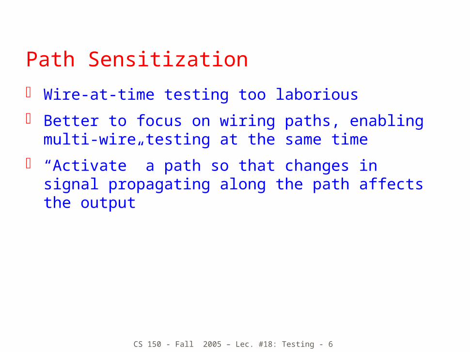
Path Sensitization
Wire-at-time testing too laborious
Better to focus on wiring paths, enabling multi-wire testing at the same time
“Activate” a path so that changes in signal propagating along the path affects the output

CS 150 - Fall 2005 – Lec. #18: Testing - 7
Path Sensitization
Simple Example:
To activate the path, set inputs so that w1 can influence f
E.g., w2 = 1, w3 = 0, w4 = 1 AND gates: one input at 1 passes the other input NOR gates: one input at 0 inverts the other input
To test: w1 set to 1 should generate f = 0 if path ok faults a/0, b/0, c/1 cause f = 1 w1 set to 0 should generate f = 1 if path ok faults a/1, b/1, c/0 cause f = 0
One test can capture several faults at once!
w1w2
b
f
c
a
w3
w4
1
0
1

CS 150 - Fall 2005 – Lec. #18: Testing - 8
Path Sensitization Good news: one test checks for several faults
Number of paths much smaller than number of wires Still an impractically large number of paths for large-
scale circuits
Path idea can be used to “propagate” a fault to the output to observe the fault Set inputs and intermediate values so as to pass an
internal wire to the output while setting inputs to drive that internal wire to a known value
If propagated value isn’t as expected, then we have found a fault on the isolated wire

CS 150 - Fall 2005 – Lec. #18: Testing - 9
Fault Propagationw1w2
b
f
c
g
w3w4
h
k
w1w2
f
w3w4
b/0
0
1
1
1
1
D D0
0D

CS 150 - Fall 2005 – Lec. #18: Testing - 10
Fault Propagationw1w2
b
f
c
g
w3w4
h
k
w1w2
fD
w3w4
g/1
1
1
0
0
0
0
D
D
D

CS 150 - Fall 2005 – Lec. #18: Testing - 11
Tree Structured Circuits To test inputs stuck-at-0 at given
AND gate Set inputs at other gates to
generate AND output of zero Force inputs at selected gate to
generate a one If f is 1 then circuit ok, else fault
To test inputs stuck-at-1 at given AND gate Drive input to test to 0, rest of
inputs driven to 1 Other gates driven with inputs that
force gates to 0 If f is 0 then fault, else OK
w1w3w4
w2w3w4
w1w2w3
f

CS 150 - Fall 2005 – Lec. #18: Testing - 12
Tree Structured Circuits
w1w3w4
w2w3w4
w1w2w3
f
12345678
w1
10001110
w3
11010100
w4
10011000
w2
01111010
w3
11010100
w4
01100111
w1
01110001
w2
01111010
w3
00101011
w1
01100111
w2
01110001
w3
01111010
w4
00101011
Stuck-at-0
Stuck-at-1
Product Term Test
100
101
011
100
Stuck-at-1
1

CS 150 - Fall 2005 – Lec. #18: Testing - 13
Random Testing
So far: deterministic testing
Alternative: random testing Generate random input patterns to distinguish between
the correct function and the faulty function
Number ofTests
ProbabilityFault
Detected
Small number of testshas reasonable
probability of findingthe fault
CS 150 - Fall 2005 – Lec. #18: Testing - 14
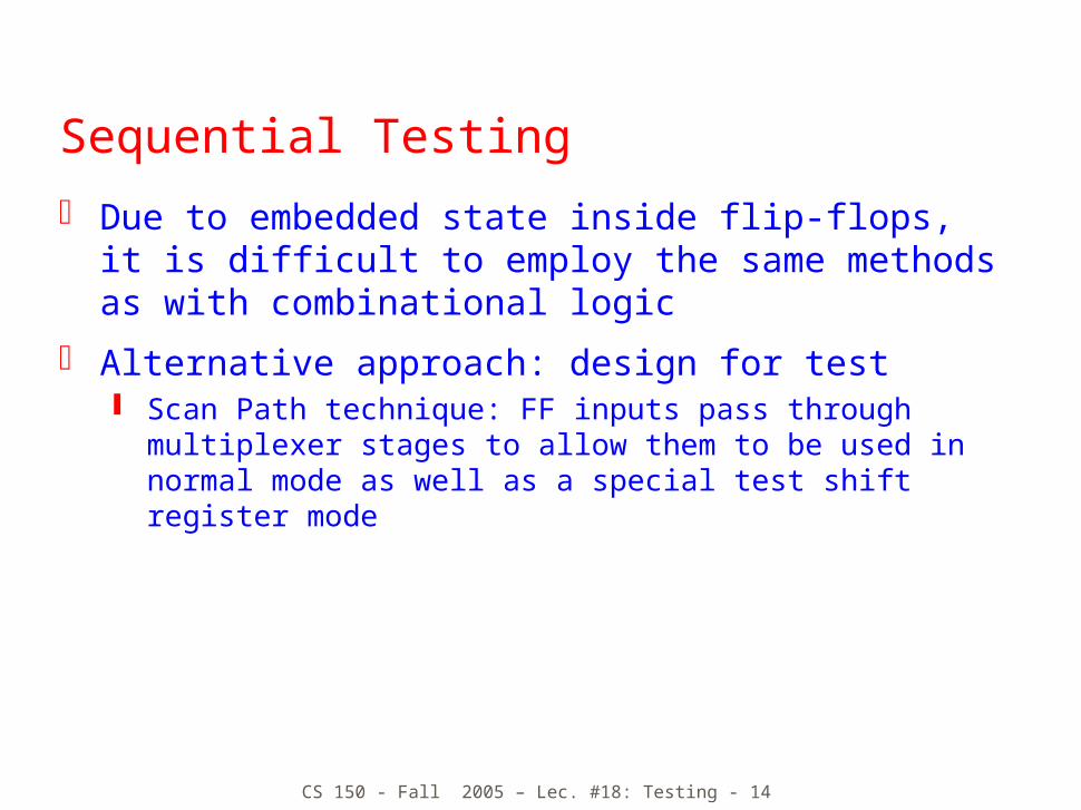
Sequential Testing
Due to embedded state inside flip-flops, it is difficult to employ the same methods as with combinational logic
Alternative approach: design for test Scan Path technique: FF inputs pass through multiplexer
stages to allow them to be used in normal mode as well as a special test shift register mode

CS 150 - Fall 2005 – Lec. #18: Testing - 15
Scan Path Technique Configure FFs into shift
register mode (red path)
Scan in test pattern of 0s and 1s
Non-state inputs can also be on the scan path (think synchronous Mealy Machine)
Run system for one clock cycle in “normal” mode (black path)—next state captured in scan path
Return to shift register mode and shift out the captured state and outputs
CombinationalLogic

CS 150 - Fall 2005 – Lec. #18: Testing - 16
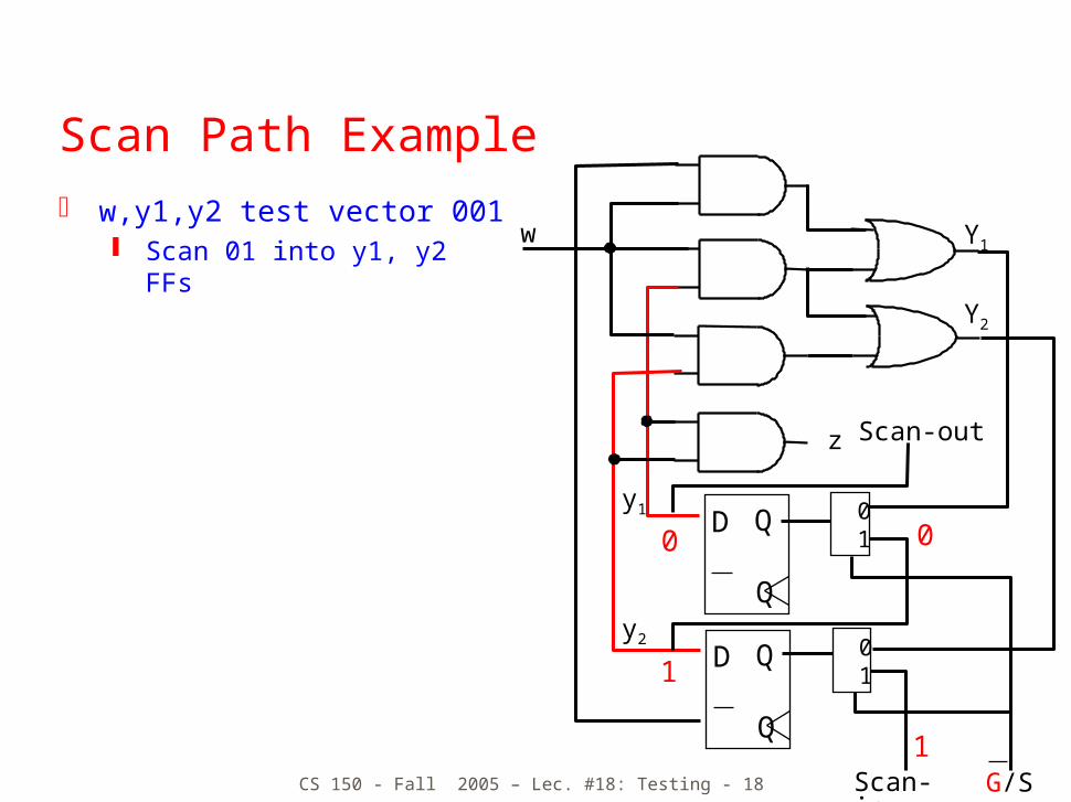
Scan Path Example w,y1,y2 test vector 001
Scan 01 into y1, y2 FFs
z
Y1
Y2
D Q
Q
D Q
Q
0 1
0 1
y1
y2
w
Scan-in
Scan-out
G/S0

CS 150 - Fall 2005 – Lec. #18: Testing - 17
Scan Path Example w,y1,y2 test vector 001
Scan 01 into y1, y2 FFs
z
Y1
Y2
D Q
Q
D Q
Q
0 1
0 1
y1
y2
w
Scan-in
Scan-out
G/S1
0
0
CS 150 - Fall 2005 – Lec. #18: Testing - 18
Scan Path Example w,y1,y2 test vector 001
Scan 01 into y1, y2 FFs
z
Y1
Y2
D Q
Q
D Q
Q
0 1
0 1
y1
y2
w
Scan-in
Scan-out
G/S1
0
1
0
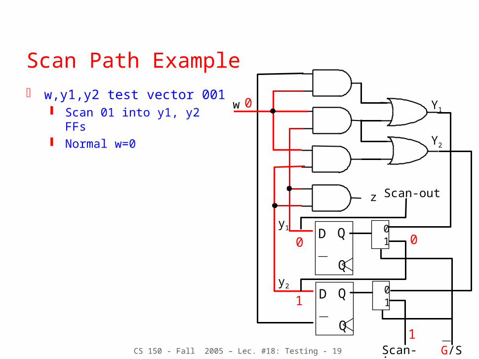
CS 150 - Fall 2005 – Lec. #18: Testing - 19
Scan Path Example w,y1,y2 test vector 001
Scan 01 into y1, y2 FFs Normal w=0
z
Y1
Y2
D Q
Q
D Q
Q
0 1
0 1
y1
y2
w
Scan-in
Scan-out
G/S1
0
1
0
0

CS 150 - Fall 2005 – Lec. #18: Testing - 20
Scan Path Example w,y1,y2 test vector 001
Scan 01 into y1, y2 FFs Normal w=0 Output z=0, Y1=0, Y2=0
z
Y1
Y2
D Q
Q
D Q
Q
0 1
0 1
y1
y2
w
Scan-in
Scan-out
G/S
1
0
0
0
0
0

CS 150 - Fall 2005 – Lec. #18: Testing - 21
Scan Path Example w,y1,y2 test vector 001
Scan 01 into y1, y2 FFs Normal w=0 Output z=0, Y1=0, Y2=0 Observe z directly
z
Y1
Y2
D Q
Q
D Q
Q
0 1
0 1
y1
y2
w
Scan-in
Scan-out
G/S
0
0
0
0
0
0

CS 150 - Fall 2005 – Lec. #18: Testing - 22
Scan Path Example w,y1,y2 test vector 001
Scan 01 into y1, y2 FFs Normal w=0 Output z=0, Y1=0, Y2=0 Observe z directly Scan out Y1, Y2
z
Y1
Y2
D Q
Q
D Q
Q
0 1
0 1
y1
y2
w
Scan-in
Scan-out
G/S
0
0
0
0

CS 150 - Fall 2005 – Lec. #18: Testing - 23
Scan Path Example w,y1,y2 test vector 001
Scan 01 into y1, y2 FFs Normal w=0 Output z=0, Y1=0, Y2=0 Observe z directly Scan out Y1, Y2
z
Y1
Y2
D Q
Q
D Q
Q
0 1
0 1
y1
y2
w
Scan-in
Scan-out
G/S
0
0
0

CS 150 - Fall 2005 – Lec. #18: Testing - 24
Built-in Self-Test (BIST)
Test Vector Generator Pseudorandom tests with a feedback shift register Seed generates a sequence of test patterns Outputs combined using the same technique Generates a unique signature that can be checked to
determine if the circuit is correct
TestVector
Generator
CircuitUnderTest
TestResponse
Compressor
x0...xn-1
P0...Pm-1
Signature

CS 150 - Fall 2005 – Lec. #18: Testing - 25
Linear Feedback Shift Register
D Q
Q
D Q
Q
D Q
Q
D Q
Q
D Q
Q
D Q
Q
D Q
Q
D Q
Q
P
Signature
Random Test Pattern
Input fromcircuit under test

CS 150 - Fall 2005 – Lec. #18: Testing - 26
Linear Feedback Shift Register
Starting with the pattern 1000, generates 15 different patterns in sequence and then repeats
Pattern 0000 is a no-no
D Q
Q
D Q
Q
D Q
Q
D Q
Q
x3 x2 x1 x0
x3
x2
x1
x0f
f
10001
11001
11101
11110
01111
10110
01011
10101
11010
01100
00111
10010
01000
00100
00011
10001
…
…
Initial Configuration

CS 150 - Fall 2005 – Lec. #18: Testing - 27
Linear Feedback Shift Register
Multi-input Compressor
D Q
Q
D Q
Q
P3 P2
D Q
Q
P1
D Q
Q
P0
Signature
Circuit Under Test Outputs

CS 150 - Fall 2005 – Lec. #18: Testing - 28
Complete Self-Test System
CombinationalCircuit
FFs andMuxes
MIC
SICScan out
PRBSGScan in
MUX
PR
BS
G
NormalInputs
RandomTestSequences
Multi-inputCompressor
RandomTestSequences
Single-inputCompressor

CS 150 - Fall 2005 – Lec. #18: Testing - 29
Built-in Logic Block Observer (Bilbo) Test generation and compression in a single circuit!
M1, M2 = 11: Regular mode M1, M2 = 00: Shift register mode M1, M2 = 10: Signature generation mode M1, M2 = 01: Reset mode
D Q
Q
D Q
Q
D Q
Q
D Q
Q
M1
P3 P2 P1P0
M2
Q3 Q2 Q1Q0
Sin
G/S
Normal/Scan

CS 150 - Fall 2005 – Lec. #18: Testing - 30
Bilbo Architecture
Scan initial pattern in Bilbo1, reset FFs in Bilbo2 Use Bilbo1 as PRBS generator for given number of clock
cycles and use Bilbo2 to produce signature Scan out Bilbo2 and compare signature; Scan in initial test
pattern for CN2; Reset the FFs in Bilbo1 Use Bilbo2 as PRBS generator for a given number of clock
cycles and use Bilbo1 to produce signature Scan out Bilbo1 and compare signature;
CombinationalNetwork
CN1
CombinationalNetwork
CN2BIL
BO
1
BIL
BO
2
Scan-in
Scan-out

CS 150 - Fall 2005 – Lec. #18: Testing - 31
Summary Fault models
Approach for determining how to develop a test pattern sequence
Weakness is the single fault assumption
Scan Path Technique for applying test inputs deep within the system,
usually for asserting state Technique for getting internal state to edges of circuit for
observation
Built-in Test Founded on the approach of random testing Generate pseudo random sequences; compute signature;
determine if signature generated is same as signature of a correctly working circuity


![[Chapter 10. Hypothesis Testing]daeyoung/Stat516/Chapter10.pdf · 2. Large sample test(Sec 10.3): An two-sided -level test of H0: = 0 vs. H a: 6= 0 is to use a Ztest based on Z= ^](https://static.fdocuments.net/doc/165x107/606c9630f59a944823770e51/chapter-10-hypothesis-testing-daeyoungstat516chapter10pdf-2-large-sample.jpg)