Crystallographic effects on the fatigue fracture of copper...
21
PHILOSOPHICAL MAGAZINE A, 2000, VOL. 80, NO. 9, 2109± 2129 Crystallographic eŒ ects on the fatigue fracture of copper± sapphire interfaces P . P ERALTA{ Department of Mechanical and Aerospace Engineering, Arizona State University, PO Box 876106, Tempe, Arizona 85287-6106, USA U. R AMAMURTY Nanyang Technological University, School of Mechanical and Production Engineering, Singapore 639798 S . SURESH Department of Materials Science and Engineering, Massachusetts Institute of Technology, Cambridge, Massachusetts 02139-4307, USA G. H. CAMPBELL, W . E. K ING Lawrence Livermore National Laboratory, Mail Stop L-356, Livermore, California 94550, USA and T . E. MITCHELL Los Alamos National Laboratory, MS K765, Los Alamos, New Mexico 87545, USA [ Received 16 June 1999 and accepted 18 October 1999] ABSTRACT Interfacial fatigue cracks were propagated in copper± sapphire bicrystals with the boundary perpendicular to the load axis and … 110† Cu jj…10 - 10† Al 2 O 3 ± ‰ 001Š Cu jj ‰ 0001Š Al 2 O 3 to study the e ect of crystallography in the fracture process. Cylindrical samples with a circumferential notch were loaded in compression± compression and compact tension specimens in tension± tension. Three interfacial cracks in the cylindrical sample nucleated simultaneously at sites corresponding to the maximum slip length, under local single slip conditions, for three of the four slip vectors expected for the h110i loading axis in the copper crystal. These cracks arrested with continued cycling, while two new cracks nucleated at 0 8 and 180 8 from ‰ 1 - 10Š Cu , which also self-arrested. Then another crack started at 90 8 from ‰ 1 - 10Š Cu and grew with an inclined front. Striations could be observed on the copper fracture surfaces; however, they did not coincide macroscopically with traces of f 111g slip planes. Large areas were also relatively free of features. Elastic analysis of the anisotropic near-tip stress ® elds for the interfacial crack revealed that the dominant crack growth direction had the highest energy release rate, whereas the second crack direction had the minimum mode II mix. A model to account for the non- crystallographic striations is proposed. Philosophical Magazine A ISSN 0141± 8610 print/ISSN 1460-6992 online # 2000 Taylor & Francis Ltd http:// www.tandf.co.uk /journals { Author for correspondence: Email: [email protected].
Transcript of Crystallographic effects on the fatigue fracture of copper...

PHILOSOPHICAL MAGAZINE A, 2000, VOL. 80, NO. 9, 2109± 2129
Crystallographic eŒects on the fatigue fracture of copper±sapphire interfaces
P. PERALTA{
Department of Mechanical and Aerospace Engineering, Arizona StateUniversity, PO Box 876106, Tempe, Arizona 85287-6106, USA
U. RAMAMURTY
Nanyang Technological University, School of Mechanical and ProductionEngineering, Singapore 639798
S. SURESH
Department of Materials Science and Engineering, Massachusetts Institute ofTechnology, Cambridge, Massachusetts 02139-4307, USA
G. H. CAMPBELL, W. E. K ING
Lawrence Livermore National Laboratory, Mail Stop L-356, Livermore,California 94550, USA
and T. E. MITCHELL
Los Alamos National Laboratory, MS K765,Los Alamos, New Mexico 87545, USA
[Received 16 June 1999 and accepted 18 October 1999]
ABSTRACTInterfacial fatigue cracks were propagated in copper± sapphire bicrystals with
the boundary perpendicular to the load axis and …110†Cu jj…10-10†Al2O3
±‰001ŠCujj‰0001ŠAl2O3
to study the e� ect of crystallography in the fracture process.Cylindrical samples with a circumferential notch were loaded in compression±compression and compact tension specimens in tension± tension. Three interfacialcracks in the cylindrical sample nucleated simultaneously at sites correspondingto the maximum slip length, under local single slip conditions, for three of thefour slip vectors expected for the h110i loading axis in the copper crystal. Thesecracks arrested with continued cycling, while two new cracks nucleated at 08 and1808 from ‰1 -
10ŠCu, which also self-arrested. Then another crack started at 908from ‰1 -
10ŠCu and grew with an inclined front. Striations could be observedon the copper fracture surfaces; however, they did not coincidemacroscopically with traces of f111g slip planes. Large areas were alsorelatively free of features. Elastic analysis of the anisotropic near-tip stress® elds for the interfacial crack revealed that the dominant crack growthdirection had the highest energy release rate, whereas the second crackdirection had the minimum mode II mix. A model to account for the non-crystallographic striations is proposed.
Philosophical Magazine A ISSN 0141± 8610 print/ISSN 1460-6992 online # 2000 Taylor & Francis Ltdhttp://www.tandf.co.uk /journals
{ Author for correspondence: Email : [email protected].

} 1. INTRODUCTIONThe fracture behaviour at metal± ceramic interfaces has received considerable
attention recently, since they are highly relevant to deformation and fracture pro-cesses in electronic components and composite materials. Interfaces that have beenstudied in great detail are those between alumina, either polycrystalline or singlecrystal, and metals, as evidenced by the extensive literature available on the topic(Reimanis et al. 1990 ; Cannon, et al. 1991, Beltz and Wang 1992, De Graef et al.1992, Evans and Dalgleish 1992, Gibbesch and Elssner 1992, McNaney et al. 1996,Mesarovic and Kysar 1996, Turner and Evans 1996, Mao and Evans 1997). Thesestudies have shown a variety of interesting phenomena associated with the fracturebehaviour at these interfaces, most of which are related to fracture under monotonicloading conditions.
Turner and Evans (1996) showed that the fracture behaviour of gold± sapphireinterfaces under monotonic loading is in¯ uenced by crystallographic slip on themetal side, for both dry and humid environments. This was evidenced by the corre-lation between features in the fracture surface and slip markings on individual grainsin the metal ® lm, which had a strong crystallographic texture. Experiments in cop-per± sapphire bicrystals by Beltz and Wang (1992) showed that there were strongdirectional e� ects on the behaviour of an interfacial crack under monotonic loading.Fatigue fracture studies in interfaces between alumina and aluminum (both poly-crystalline) (Cannon, et al. 1991, McNaney et al. 1996) have shown that fatiguecracks tend to stay at the interface for low and medium values of the loading andthat striations are indeed formed on the metal side, implying that plastic blunting ofthe crack tip is likely to play an important role in the growth of fatigue cracks atthese interfaces. The local crystallography and slip geometry play a signi® cant role indetermining the fracture behaviour in metals loaded under cyclic conditions. Thishas been shown for single crystals and bicrystals of pure metals (Laird 1967,Neumann 1974, Peralta and Laird 1998), where fatigue cracks grow through a`double-forward-slip’ mechanism whereby two slip bands form a V shape ahead ofthe tip, producing plastic blunting at both sides of the fracture plane. In addition,fatigue cracks follow a path that provides the optimum slip conditions for this plasticblunting process (Laird 1967, Neumann 1974, Peralta and Laird 1998). The doubleforward slip needed to produce plastic blunting in this fashion is not possible forcracks along metal± oxide interfaces, since in most cases only the metal side canprovide crystallographic slip. Therefore, the strong constraints produced by thesapphire are likely to a� ect signi® cantly the mechanisms for fatigue crack nucleationand growth along copper± sapphire interfaces. This poses questions about the speci® cmechanisms for interfacial crack growth in this bimaterial system and their preciserelationship to the slip geometry on the metal side. In addition, whether or notinterfacial fatigue cracks in this system will follow a `preferred’ path determinedby the slip geometry and/or the general crystallography is still unknown. Themode mix expected at the crack tip due to the mismatch of the material propertiesacross the interface is also likely to play an important role. These issues have notbeen addressed in detail for metal± oxide interfaces to the best of the present authors’knowledge. Therefore, experiments were performed in copper± sapphire bicrystalsoriented such that …110†Cujj…10
-10†Al2O3
± [001]Cujj‰0001ŠAl2O3. Bicrystals were used
because they are well suited to study the in¯ uence of slip geometry on fatiguefracture along metal± oxide interfaces. A cylindrical specimen with a circumferentialnotch was used to study the tendency of the crack to grow along particular
2110 P. Peralta et al.

crystallographic directions. Conversely, compact tension specimens were used tostudy the behaviour when both the crack front and the growth direction are con-strained because of the specimen geometry.
} 2. EXPERIMENTAL DETAILSThe copper± sapphire bicrystals were prepared by di� usion bonding. The sap-
phire crystals were cylindrical rods, 19.1 mm (0.75 inch) in diameter by 12.7 mm(0.5 inch) in length, with their axes aligned along ‰10
-10Š to within §0:18 and the
faces polished ¯ at to within ¶=10. The copper single crystals were nominally99.999% pure. They were also cylinders, 19.1 mm (0.75 inch) in diameter and25.4 mm (1.0 inch) long, with their axes approximately along [110]. These singlecrystals had their faces polished parallel to (110) to within §0:18 and ¯ at to lessthan 100 nm by specially developed techniques (Wien et al. 1996). The [001] directionin the copper crystals and the [0001] direction in the sapphire crystals were mutuallyaligned to within §0:18 (both directions are perpendicular to the cylinder axis) and areference ¯ at was ground simultaneously in the walls of each pair of cylinders. This¯ at was used to realign the crystals immediately prior to bonding.
The crystals were bonded in an ultrahigh-vacuum di� usion bonding machine(King et al. 1993). The surfaces were sputtered at a glancing angle of 158 with500 eV xenon ions while the specimens rotated in order to maintain ¯ at surfaces.The as-introduced sapphire surface was sputtered for 5 min, followed by an anneal at11008C for 4 h to outgas the other surfaces. The as-introduced copper crystal wassputtered for 5 min followed by an anneal at 6008C for approximately 16 h. After theannealing treatments, both crystals were sputtered again for 5 min and the surfacescharacterized by Auger electron spectroscopy to con® rm that they were free fromcontamination. The surfaces to be bonded were then placed in contact and theirmutual orientation re-established by re¯ ecting a laser from the reference ¯ at placedon the sides of the cylinders. A pressure of 5 MPa was applied to the specimen stackand it was held at 9508C for a period of 48 h. These conditions were observed toproduce an interface free from residual porosity. The specimens were kept underultrahigh-vacuum conditions throughout the process. An outline of the crystallogra-phy and dimensions corresponding to each material and the slip geometry on themetal side is shown in ® gure 1.
A circumferential notch about 2.5 mm deep was introduced at the interface of thespecimen with a diamond blade. The notch root radius was approximately 0.5 mm.Care was taken to ensure that the notch tip was exactly at the interface. The exposureof the sample to water was minimized to reduce the possibility of stress corrosioncracking.
The circumferentially notched specimen was subjected to compression± compres-sion loading in a servohydraulic machine operating in load control using a sinewaveform at a frequency of 20 Hz. The fatigue tests were conducted such that themaximum load in each cycle was approximately zero. The specimen was removedfrom the machine periodically and the interface was examined through the sapphire,which was transparent, for any signs of crack growth. The sample was broken usingmonotonic tension once the fatigue cracks arrested.
Fatigue fracture of copper± sapphire interfaces 2111

} 3. R ESULTS
3.1. Cylindrical specimenTests were started at a stress amplitude D ¼ ˆ ¡20 MPa. No fatigue crack growth
was observed even after 100 000 cycles. The absolute value of the stress amplitudewas then increased in 5 MPa increments and tests were continued. Crack growth was® rst observed at a stress amplitude of ¡40 MPa after 6000 cycles. Three initiationsites were observed located at approximately 1258, 2168 and 3058 (¡558) from the xaxis, which was chosen parallel to [001]Cu. Positive angles were measured counter-clockwise. A schematic diagram is outlined in ® gure 2. A picture showing the thumb-
2112 P. Peralta et al.
Figure 1. (a) Dimensions and crystallography of the cylindrical copper± sapphire bicrystals;(b) Slip geometry on the copper side.

nail crack that developed from the nucleation site at ¡558 can be seen in ® gure 3, asobserved on the copper fracture surface once the sample was broken. The front ofthis crack was parallel to the trace of …1 -
1-1) on the (110) plane of copper. The
markings in front of the thick line where the crack ® rst arrested suggest that propa-gation took place along a direction perpendicular to the …1
-1
-1† slip trace, with the
crack front parallel to that trace.The thumbnail cracks did not grow any further after an extension of about
1.5 mm, implying that there was no further driving force for crack growth in theseparticular directions. This is to be expected since compression± compression fatiguecrack growth is self-arresting in nature (Suresh 1985), which also explains the
Fatigue fracture of copper± sapphire interfaces 2113
Figure 2. Outline of the positions of initial crack nucleation sites.
Figure 3. Nucleation site at 3058 (¡558) from [001]Cu as seen on the copper fracture surface.

decrease in the spacing of the markings ahead of the nucleation site shown in ® gure3. Consequently, the stress amplitude was changed to ¡50 MPa. Figure 4 shows theevolution of crack growth for the di� erent load levels used. After 8000 cycles at thisstress amplitude, two new crack growth sites, at 908 and ¡908 from the [001]Cu xaxis, were noticed. This was accompanied by some extension in the cracks thatnucleated previously at D ¼ ˆ ¡40 MPa, as shown in ® gure 4 (a). Further cyclingresulted in the arrest of the initial cracks and additional growth of the new cracks(® gure 4 (b)).
Further growth proceeded along the 908 and ¡908 directions, that is ‰1 -10ŠCu and
‰ -110ŠCu, with crack fronts parallel to [001]Cu, until the cracks arrested. Then, cracksstarted at 08 and 1808 from [001]Cu ( ® gure 4 (c)). The crack growing along ‰00
-1ŠCu
(1808, crack front parallel to ‰1 -10ŠCu) arrested quickly, whereas that growing along
[001] Cu (08, crack front parallel to ‰1 -10ŠCu) continued to grow and merged with the
crack resulting from the nucleation site in the third quadrant (1808 < ³ < 2708),which had a front at approximately 368 from ‰1 -
10ŠCu. This crack ® nallyarrested with a well de® ned straight front at about 128 from ‰1 -
10ŠCu ( ® gure 4 (d)).No further crack growth could be induced at this point and the sample was broken intension. Both the copper and the sapphire side were examined to determine whetherthere was residue of one material on the fracture surface of the other. No sapphirecould be found on the copper (scanning electron microscopy examination) and thesapphire was optically transparent, these indicate that the fracture was completelyinterfacial. This agrees with results obtained in Al=Al2O3 polycrystalline specimenstested under tensile loads (Cannon, et al. 1991, McNaney et al. 1996).
2114 P. Peralta et al.
Figure 4. Evolution of the crack fronts as a function of cycles and loads. (a) 8000 cycles atD ¼ ˆ ¡50 MPa; (b) 8000 cycles at D ¼ ˆ ¡60 MPa; (c) 6000 additional cycles atD ¼ ˆ ¡60 MPa; (d) ® nal fracture.

Micrographs of the copper fracture surface, including details of striations leftbehind are shown in ® gure 5. The overall copper fracture surface shown in ® gure5 (a) has a region towards the centre of the fracture surface that is quite di� erentfrom the surrounding area. This corresponds to the ® nal fracture produced in mono-tonic tension, which has all the aspect of brittle fracture. No indications of dimpleswere found, but the area has abundant slip bands and other straight features parallelto the traces of the f111gCu slip planes on the (110)Cu fracture plane. Note that theshape of the ® nal fracture also de® nes the geometry of the fatigue crack fronts at thelocations where they arrested. It is clear that the ® rst two long cracks had frontsapproximately parallel to [001]Cu, at least in a piecewise fashion, since the cracksarrested close to the centre but continued to propagate close to the edge, whichproduced a curved transition region. As noted before, the crack that propagatedalong ‰00
-1ŠCu (top of ® gure 5 (a)) arrested quickly (note the edge of the sample at the
upper left corner of the ® gure), whereas that along [001] grew to a length of more
Fatigue fracture of copper± sapphire interfaces 2115
Figure 5. Copper fracture surface. (a) overall fracture surface; (b) detail of site A ; (c) detail ofsite B.

than 6 mm. This crack seems to have initiated at two locations. One had a wellde® ned straight front at 368 from ‰1 -
10ŠCu, which corresponds to the crack nucleationsite found in the third quadrant (1808 < ³ < 2708). This location is labelled A in® gure 5 (a) and a higher-magni® cation picture is shown in ® gure 5 (b). The otherlocation, labelled B in ® gure 5 (a) and shown in more detail in ® gure 5 (c), had acurved front that was, on average, parallel to ‰1 -
10ŠCu.The area corresponding to the growth of the last crack along [001]Cu had large
spaces almost free of features, except for straight slip traces close to the ® nal crackfront and the striations close to the two initiation sites ( ® gure 5 (b) and (c)). Note thattheir spacing decreases as the crack length increases, just like the markings observed
2116 P. Peralta et al.
Figure 5. (Continued )
in ® gure 3. This indicates that cracks were driven by a decreasing tensile stress ® eld,which made them self-arresting. This behaviour is similar to that observed in puremetallic samples where cracks have been propagated from notches using compres-sion± compression fatigue (Suresh 1985). It can also be seen that the striations are notalways parallel to the traces of the f111gCu planes on the boundary. This is quitedi� erent from the behaviour observed in copper single crystals and bicrystals, wherestriations are often locally parallel to the trace of a slip plane on the boundary (Laird1967, Peralta and Laird 1998).
3.2. Compact tension specimenGiven the results obtained in the cylindrical specimen, it was decided to use
another cylindrical bicrystal with the same misorientation to manufacture compacttension specimens with two di� erent orientations. The dimensions and crystallogra-phy of these specimens are shown in ® gure 6. The ® rst orientation, which is labelledCT1, is such that the crack propagation direction x1 is parallel to ‰1 -
10ŠCu and theexpected crack front x3 is parallel to [001]Cu , which is the ® rst preferred orientationfor cracking observed in the cylindrical specimen. The second orientation, labelledCT2, was chosen at 908 from the previous orientation, that is the crack propagationdirection x1 along [001]Cu and the crack front x3 parallel to ‰1 -
10ŠCu (close to thesecond preferred direction). The interface was perpendicular to the loading axis.Interfacial fatigue cracks were initiated using tension± tension in this case.
The tension± tension cycling on these specimens resulted in an applied D K ofabout 2 MPa m1=2 (far ® eld). The crack in sample CT1 nucleated at one side of thenotch and propagated quickly along the ‰1 -
10ŠCu direction, as expected, since this wasthe preferred crack growth direction found in the cylindrical specimen. This crackarrested at a maximum penetration of about 3 mm and kinked into the sapphirefollowing the trace of a f10
-11gAl2O3
plane, which can be deduced from the fact that along section of the crack front before the kink was parallel to the trace of this plane,as shown in ® gure 7. The copper fracture surface was almost free of features, withonly some slip bands parallel to the …1 -
1-1†Cu trace. Note that the crack front is only
straight at the region of maximum penetration. The sample with the second orienta-tion, namely sample CT2, showed a completely di� erent behaviour. Heavy slip bandactivity at the notch in the metal side, as shown in ® gure 8, seems to have blunted thenotch tip and favoured cracking in the sapphire. The crack propagated mostlythrough the sapphire (® gure 9) and reached the interface in a narrow region locatedaround the middle of the initial unbroken section, only to kink back into the sap-phire. The interfacial crack left well de® ned striations on the copper side. Thesestriations where inclined approximately 288 from the expected macroscopic crackfront direction (parallel to ‰1 -
10ŠCu). Figure 10 is a light micrograph of the striationsfor this particular sample. Note that they are regularly spaced and they `wiggle’instead of being completely straight. They also run along a direction, approximatelyparallel to ‰ -
443ŠCu, that is not related to the trace of any of the four available f111gCuslip planes, which are also shown in the ® gure. The crack front orientation forspecimen CT2 (288) was close to that of the average orientation of the secondcrack front in the cylindrical sample (248), which suggests that there are preferredcrystallographic orientations for both the crack front and the propagation direc-tions. There must be a close relationship between these preferred directions andthe stress ® eld at the crack tip and its variations with orientation. In order to explore
Fatigue fracture of copper± sapphire interfaces 2117

2118 P. Peralta et al.
Figure 6. Dimensions and crystallography for the compact tension specimens.
Figure 7. Fracture surface of sample CT1 after the test.

Fatigue fracture of copper± sapphire interfaces 2119
Figure 8. Lateral view of sample CT2 during the test.
Figure 9. Fracture surface of sample CT2 after the test.
Figure 10. Striations produced by the interfacial crack in sample CT2. A slip band along…1 -
11† is indicated by arrows.

this relationship a simpli® ed analysis of the crack tip ® elds is undertaken in the nextsection.
3.3. Analysis of near-tip ® eldsThe geometry of the specimen used, the way that the cracks propagated and the
fact that the fatigue fracture process in compression± compression is driven by resi-dual tensile stresses (Suresh 1985) made the fracture problem in the cylindrical speci-mens quite di� cult to treat analytically. It was decided to use a simpli® ed modelpresented by Qu and Bassani (1993) that is based on the near-tip elastic ® elds for aplane strain crack between two anisotropic materials. These near-tip ® elds werederived from the elastic solution to a Gri� th crack along a bimaterial interface.The behaviour of the near tip ® eld for this case, as a� ected by the variation in thematerial properties due to the anisotropy, should resemble that of the actual crack inthe compact tension specimens and the general features of the fracture process in thecylindrical specimen are probably also captured this way. No attempts were made toestimate a stress intensity factor and only qualitative comparisons are sought withthis calculation.
The coordinate system used is shown in ® gure 11. Note that the direction per-pendicular to the crack plane is always x2 ˆ ‰110ŠCu and that the crack growthdirection is always x1, whereas the crack front is parallel to x3. The applied tractionsin the compact tension specimens and those produced by the residual stresses in thecylindrical specimens are assumed to be homogeneous and only mode I. This open-ing load is given unitary value to have the results normalized per unit of appliedstress. The tractions at the interface at a distance x1 ahead of the crack tip for thecoordinate system used are given by
t…x1† ˆ… a2x1
†1=2
Y …1 ‡ 2i"†…x1
2a†i"
qa ˆ ‰¼12 ¼22 ¼23ŠT ; …1†
where a is the crack length, qa is the generalized applied traction vector, whichis assumed to be equal to [0 1 0]T in this case, and " can be calculated as
" ˆ 12º
ln1 ‡
1 ¡ … †: …2†
The term is in turn de® ned as
ˆ ‰¡ 12 Tr…WD¡1†Š1=2
: …3†
2120 P. Peralta et al.
Figure 11. Coordinate system used for the elastic analysis of the crack tip ® elds.

Finally, the matrix function Y is given by
Y‰²Š ˆ I ¡Im…²†
D¡1W‡ 1 ¡ Re…²†
2 …D¡1W†2; …4†
where ² is the complex argument of Y, and it depends on ";x1, and a (see equation(1)).
The matrices W and D depend on the elastic properties of the two materials andare obtained using the Barnett± Lothe tensors L and S. The procedure has been givenby Qu and Li (1993). This allows calculation of the elastic ® elds without solving thenon-linear eigenvalue problem used by Qu and Bassani (1993). Further details havebeen given by Qu and Li (1993).
The elastic properties of the materials are obtained as a function of the angle ³(see ® gure 11) using the corresponding transformation rule for fourth-order sti� nesstensors. These rotated tensors are then used to obtain W and D as functions of ³.Only directions contained in the plane of the interface are considered. The values ofthe elastic properties along the principal axes used for copper and sapphire areshown in table 1 (Simmons and Herbert 1971).
Once the tractions at the interface are obtained, the mode mix of the ® elds, as afunction of x1, is calculated using a de® nition that is the inverse of that used by Boseand Ponte-CastanÄ eda (1995), that is the mode II mix is de® ned as
·II‰x1Š ˆ 2º
tan¡1 ¼12‰x1Š¼22‰x1Š… †; …5†
whereas the mode III mix is de® ned as
·III‰x1Š ˆ 2º
tan¡1 ¼23‰x1Š¼22‰x1Š… †: …6†
The tractions and the mode mix change as a function of distance from the crack tipowing to oscillatory nature of the ® elds (Qu and Bassani 1993). These variables werethen obtained along the interface at a very short distance ahead of the crack tip. Acharacteristic length related to the sample is often used to evaluate the ® elds and tode® ne the mode mix or phase angle due to the presence of three traction components.In the absence of a characteristic length, and in problems related to dislocationemission from crack tips, the length of the Burgers vector of the dislocations inthe metal side has been the parameter of choice (Wang and Beltz 1995) because ofthe very slow oscillation of the ® elds for small values of x1 (Wang and Beltz 1995).
Fatigue fracture of copper± sapphire interfaces 2121
Table 1. Elastic constants for copper and sapphire(Simmons and Herbert 1971).
Value (GPa) for the followingElasticconstant Copper Sapphire
C1111 166.1 496.7C1122 119.9 163.4C1313 75.6 147.4C1133 119.9 110.7C3333 166.1 498.0C1123 0 ¡23:5

The mode II and III mixes due to the tractions one Burgers vector ahead of the cracktip are shown in ® gure 12. It was found that the value of crack length used changedthe value of the mixes slightly, but the general behaviour in terms of locations ofmaxima and minima, and the general shapes of the curves as a function of ³ were nota� ected by a. The values reported correspond to a crack length of 6 mm. Note thatthere is a clear dependence on the angle of the crack growth direction (or crack
2122 P. Peralta et al.
Figure 12. Mode mixes as a function of the angle of rotation about [110]Cu. (a) mode II ; (b)mode III.

front). The mode II mix (® gure 12 (a)) is particularly interesting, since its lowestabsolute value, a local maximum in this case, is located at an angle of 298, and itshighest absolute value, a local minimum, is located at 908.
Finally, the energy release rate, per unit crack length, was also obtained in thiscase using the expression given by Qu and Bassani (1993), that is
Grel
aˆ º
4qT
a DY1 ‡ 4"2
cosh2…º"†
" #qa: …7†
The variation in Grel=a with the angle ³ is shown in ® gure 13. Note that the max-imum energy release occurs for ³ ˆ 908, which corresponds to a crack front parallelto [001]Cu and growth direction parallel to ‰1 -
10ŠCu.
} 4. DISCUSSION
4.1. Crack nucleationIt can be argued there should have been four crack nucleation sites, by symmetry.
The absence of a nucleation site at the ® rst quadrant (08 < ³ < 908) of the interfaceplane (see ® gure 2) could be related to irregularities in the notch geometry anddeviations resulting from the alignment of the single crystal and the testing set-uprather than to an intrinsic crystallographic mechanism. In addition, once a singlecrack nucleates at a particular location the symmetry is broken. Nevertheless, thewell de® ned locations of the nucleation sites suggest that a correlation exists betweenthe position of these sites and the slip geometry on the copper side. Kim and Laird(1978) have suggested that crack nucleation at copper grain boundaries is favouredby having Burgers vectors oriented such that they have a long slip length towards theboundary. The slip length was plotted for the four slip systems with the highestSchmid factors in a copper single crystal with a [110] loading axis : (111)‰10
-1Š,
(111)‰01-1Š, …11
-1†[101], and …11
-1†[011] (all with Schmidt factors of 0.408). This was
Fatigue fracture of copper± sapphire interfaces 2123
Figure 13. Energy release rate per unit crack length as a function of the angle of rotationabout [110]Cu.

done by ® nding the length of lines parallel to the corresponding Burgers vectorsstarting at a point at the outer diameter of the cylindrical copper crystal and endingeither at a certain depth inside the crystal or at the intersection with its surface. If thedirection of the Burgers vector is such that the line immediately extends outside thecylinder, then the slip length is taken to be zero. The starting point is then changedand the process repeated until the perimeter of the cross section is covered. Anoutline of this procedure is shown in ® gure 14 (a) and a three-dimensional depictionof the slip lengths is presented in ® gure 14 (b) for two of the four Burgers vectorsused.
The resulting slip length as a function of the angle ³, which de® nes the positionon the perimeter of the cross section, is shown in ® gure 15 for the four slip vectorsstudied. Note that the angles for maximum slip length are located at 35.268, 144.748,215.268 and 324.748 from [001]Cu. The third location is in good agreement with theposition of the crack nucleation site in the third quadrant (2168). The sites at 3058
2124 P. Peralta et al.
Figure 14. (a) Geometry and coordinate system used to obtain the slip length: (b) three-dimensional depiction of the variation in slip length for two Burgers vectors, [011] and[101], as a function of angular position.
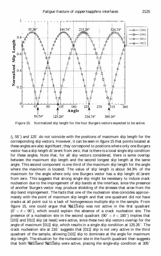
(¡558) and 1258 do not coincide with the positions of maximum slip length for thecorresponding slip vectors. However, it can be seen in ® gure 15 that points located atthese angles are also signi® cant ; they correspond to positions where only one Burgersvector has a slip length di� erent from zero, that is there is a local single slip conditionfor these angles. Note that, for all slip vectors considered, there is some overlapbetween the maximum slip length and the second longest slip length at the sameangle. This second component is one third of the maximum slip length for the anglewhere the maximum is located. The value of slip length is about 94.3% of themaximum for the angle where only one Burgers vector has a slip length di� erentfrom zero. This suggests that strong single slip might be necessary to induce cracknucleation due to the impingement of slip bands at the interface, since the presenceof another Burgers vector may produce shielding of the stresses that arise from theslip band impingement. The facts that one of the nucleation sites coincides approxi-mately with the point of maximum slip length and that one quadrant did not havecracks at all point out to a lack of homogeneous multiple slip in the sample. From® gure 15, one could argue that ‰01
-1Š slip was not active in the ® rst quadrant
(08 < ³ < 908), which would explain the absence of a crack nucleation site. Thepresence of a nucleation site in the second quadrant (908 < ³ < 1808) implies that[101] and [011] slip (at least) were active, since these two slip vectors overlap for theangle of maximum [011] slip, which results in a single slip condition at 125.268. Thecrack nucleation site at 2168 suggests that [011] slip is not very active in the thirdquadrant of the sample, allowing [101] slip to dominate at the angle for maximumslip length. The situation for the nucleation site in the fourth quadrant then suggeststhat both ‰00
-1Š and ‰10
-1Š slip were active, placing the single-slip condition at 3058
Fatigue fracture of copper± sapphire interfaces 2125
Figure 15. Normalized slip length for the four Burgers vectors expected to be active.

(¡558). Inhomogeneous distribution of slip in fatigue of copper single crystalsoriented for multiple slip has been observed (Gong et al. 1997) and it is usuallyrelated to misalignments during preparation and testing of the samples.Nevertheless, the fact that a correlation can be established between the location ofthe nucleation sites and the slip geometry indicates that crack nucleation at theinterface is controlled by the slip process in the copper side.
4.2. Crack propagationThe fact that the initial cracks arrested rather quickly indicates that their growth
directions were not favourable for crack propagation. Furthermore, the cracks thatdominated the growth in the second stage, that is those with crack fronts approxi-mately parallel to [001]Cu, grew along a direction with the maximum energy releaserate ( ® gure 13), which is one of the criteria used for mixed mode crack growth (Qianand Fatemi 1996). The fact that this is also the orientation with the maximumabsolute values of mode II mix complicates the interpretation of the results, sinceit would be expected that the crack would prefer to propagate along a direction withmaximum opening load, that is minimum mode II. However, it is interesting that themode II mix predicted by the near-tip ® elds is negative, that is the shear stress isnegative. Given that the metal is in the lower half of the sample and sapphire in theupper part, the negative shear will act at the crack tip as depicted in ® gure 16. Anopening e� ect due to a similar shear con® guration at an interface between a ductileand a rigid material was discussed by Bose and Ponte-CastanÄ eda (1995). The cop-per± sapphire samples should make a good approximation to a ductile± rigid materialcombination and it is then likely that the negative shear at the crack tip actuallyenhances crack opening.
The second dominant crack front in the cylindrical specimen (in average) and theobserved striation markings in the compact tension specimens are approximatelylocated at 24± 288 from ‰1 -
10ŠCu. This angular range agrees quite well with theangle for minimum mode II mix, which is about 298 (see ® gure 12 (a)). The energyrelease rate for this con® guration is not maximum (it is about 23% lower than themaximum), but the mode II mix is a minimum, so the opening load component is thehighest for all angles, which is also a common criterion for mixed mode crackpropagation (Qian and Fatemi 1996). This is in addition to the opening e� ect pro-duced by the negative shear that was discussed above. The experiments and theanalysis show that, when the crack can grow along any direction (cylindrical speci-men), it prefers to follow the direction of maximum energy release ® rst and theminimum mode II mix second. When the crack growth direction is imposed (com-pact tension specimen), then the crack front chooses the closest favourable con® g-uration, which in the case of sample CT1 was that with the highest energy releaserate and for specimen CT2 the crack front rotated to the con® guration with the
2126 P. Peralta et al.
Figure 16. Negative shear at the crack tip.

lowest mode II mix. The experiments on the compact tension samples con® rm quiteclearly that orientation CT1 favours crack propagation along the interface, probablyby a decohesion mechanism, since the copper fracture surface does not show crackblunting marks such as those seen in orientation CT2. These marks suggest thatenergy is spent to produce plastic deformation on the copper side for orientationCT2, which must increase the toughness of the interface.
The formation of the striations left by the crack in specimen CT2 also deservessome close attention. As pointed out before, these markings are not macroscopicallyparallel to the traces of the f111g slip planes, as is usually the case for fatigue cracksin the bulk of copper single crystals (Laird 1967, Neumann 1974) and at the interfaceof ductile bicrystals (Wang and Mesarovic 1995, Peralta and Laird 1998). The factthat only f111g slip planes operate in copper indicates that these markings must haveoriginated from a combination of two or more slip planes alternating in such a waythat the combination of their two traces results in the macroscopic 288 angleobserved. One possibility is a combination of one slip plane with a trace at 54.748from ‰1 -
10ŠCu and another with a trace parallel to ‰1 -10ŠCu. The vector sum of the two
traces in the correct proportions could then result in an overall 288 angle. An outlineof the proposed mechanism is shown in ® gure 17, where a and b refer to the magni-tudes of the two slip traces and c is the length of the resultant macroscopic vector at288 from ‰1 -
10ŠCu. It is easy to show that only a particular value of b/a results in theexpected macroscopic angle, since, in this case
a‰cos 54:748 sin 54:748ŠT ‡ b‰cos 08 sin 08ŠT ˆ c‰cos 288 sin 288ŠT ; …8†which results in the following conditions :
ca
ˆ sin 54:748
sin 288º 1:74 ;
ba
ˆ sin 54:48
tan 288¡ cos 54:748 º 0:96: …9†
These simple relationships suggest that alternating activation of two slip planes withtraces at 54.748 and 08 of approximately equal lengths will result in a macroscopicangle of 288. This would result in a `zigzag’ pattern at the microscopic level thatcould explain the fact that the striations `wiggle’ . Support for this idea was found in asection of the crack surface shown in ® gure 10, where the steps along the twopredicted traces close to a large slip band (indicated by arrows) are large enoughto be seen at relatively low magni® cation. Note that a large step along the …1 -
11†Cutrace (54.748) is followed by another step along the (111)Cu trace (08) and in somecases another segment parallel to the … -
111†Cu trace. The large steps at 54.748 occuralong the slip band, which indicates that a high plastic strain is present locally. Thefact that such a large step resulted in another step at 08, and even small steps along
Fatigue fracture of copper± sapphire interfaces 2127
Figure 17. Proposed mechanism to obtain a crack front at 288 from the activation of slipplanes with traces at 57.748 and 08.

the … -111†Cu trace, suggests that the slip at the crack tip balances itself in order to keep
the crack front parallel to the preferred direction.Note that, in theory, any macroscopic direction between 08 and 54.748 can be
obtained by setting an adequate value for b=a. The involvement of another slip tracewould make it possible to obtain arbitrary angles, which can probably explain thecurved striations observed on the fracture surface of the cylindrical specimen.
} 5. CONCLUSIONSInterfacial fatigue fracture experiments in copper± sapphire bicrystals yield the
following conclusions.
(1) Interfacial fatigue cracks can be propagated at metal± ceramic interfacesusing compression± compression loading.
(2) Crack nucleation at the copper± sapphire interface tested is dominated byslip processes on the metal side. A simple geometrical analysis suggests thatlong slip lengths and local single slip conditions are necessary to producecrack nucleation at a given location.
(3) The results obtained show that there are two preferred directions for crackpropagation along the studied copper± sapphire interface, with one of thesedirections taking preference over the other. The ® rst preferred crack direc-tion corresponds to growth along the ‰1 -
10ŠCu direction and the second is at288 from [001]Cu. When a crack growth direction is forced’ on the specimen,as was the case in the compact tension samples, the crack adopts the pre-ferred direction closest to the imposed one.
(4) The preferred directions for crack propagation observed for the particularmisorientation studied could be predicted fairly well by a simple anisotropicelastic analysis of the variation in the stress ® elds at the crack tip as afunction of the orientation of the crack front on the plane of the interface.It was found that the energy release rate is maximized for the ® rst preferreddirection. This orientation also has the maximum mode II mix and it issuggested that the negative shear present at the crack tip, as predicted bythe elastic analysis, actually enhances opening of the crack, which in turnfavours crack propagation. The second preferred direction corresponds toan orientation where the mode II mix has a minimum absolute value, that ismaximum ratio of opening to shear modes.
(5) The striation markings left behind on the copper side by the crack as it grewdid not correspond to the traces of the slip planes on the interface plane. Itwas found that the activation of at least two slip planes with non-paralleltraces could account for the macroscopic angle of 288 from ‰1 -
10ŠCu observedin the compact tension specimen as long as they form a zigzag pattern.Evidence for this was found in a section of the copper fracture surface ofa compact tension specimen. A variation in the length of the trace of eachplane in the zigzag pattern can explain the presence of the curved markingsobserved on the fracture surface of the cylindrical specimen.
(6) The propagation of the fatigue crack at the interface is probably due to acombination of plastic blunting via crystallographic slip and brittle debond-ing processes, since there are large regions at the fracture surface that arefree of features and the crack arrest markings did not correspond to thetraces of the f111g slip planes with forward’ con® gurations, which is usually
2128 P. Peralta et al.

the case in single crystals and bicrystals of ductile metals (Laird 1967,Neumann 1974, Peralta and Laird 1998), where this con® guration leads toenhanced fatigue crack growth.
Note that hexagonal symmetry was assumed for sapphire in order to simplify thiscalculation. Preliminary results indicate that the magnitude of the mode II mix andthe energy release rate change by only about 3% using trigonal symmetry.
ACKNOWLEDGEMENTS
This research was supported by the US Department of Energy, O� ce of BasicEnergy Science, Materials Science Division. P. Peralta acknowledges a DirectorFunded Postdoctoral Fellowship at Los Alamos National Laboratory and a start-up grant from Arizona State University.
REFERENCESBELTZ, G. E., and WANG, J.-S., 1992, Acta metall. mater., 40, 1675.BOSE,K., and PONTE-CASTANEDA,P.,1995, Fracture Mechanics: 25th V olume, ASTM Special
Technical Publication 1220, edited by F. Erdogan (Philadelphia, Pennsylvania:American Society for Testing and Materials), p. 106.
CANNON,R.M.,DALGLEISH,B. J.,DAUSKARDT,R.H.,OH,T.S., and R ITCHIE,R.O., 1991,Acta metall. mater., 39, 2145.
DE GRAEF, M., DALGLEISH, B. J., TURNER, M. R., and EVANS, A. G., 1992, Acta metall.mater., 40, S333.
EVANS, A. G., and DALGLEISH, B. J., 1992, Acta metall. mater., 40, S295.G IBBESCH, B., and ELSSNER, G., 1992, Acta metall. mater., 40, S59.GONG, B., WANG, Z., WANG, Z.-G., 1997, Acta mater., 45, 1365.K IM, W. H., and LAIRD, C., 1978, Acta metall., 26 , 789.K ING, W. E., CAMPBELL, G. H., COOMBS, A. W., JOHNSON, G. W., KELLY, B. E., REITZ, T.
C., STONER, S. L., WIEN, W. L., and WILSON, D. M., 1993, Joining and Adhesion ofAdvanced Inorganic Materials, (Pittsburgh, Pennsylvania: Materials Research Society),pp. 61± 67.
LAIRD, C., 1967, Fatigue Crack Propagation , ASTM Special Technical Publication (Philadel-phia, Pennsylvania: American Society of Testing and Materials), p. 131.
MAO, S. X., and EVANS, A. G., 1997, Acta mater., 45, 4663.MCNANEY, J. M., CANNON, R. M., and R ITCHIE, R. O., 1996, Acta mater., 44, 4713.MESAROVIC, S. D., and KYSAR, J. W., 1996, Mech. Mater., 23, 271.NEUMANN, P., 1974, Acta metall., 22, 1155.PERALTA, P., and LAIRD, C., 1998, Acta mater., 46, 2001.QIAN, J., and FATEMI, A., 1996, Engng. Fracture Mech., 55, 969.QU, J., and BASSANI, J. L., 1993, J. appl. Mech., 60, 422.QU, J., and LI, Q., 1993, J. Elasticity, 26, 169.REIMANIS, I. E., DALGLEISH, B. J., BRAHY, M., RUïHLE, M., and EVANS, A. G., 1990, Acta
metall. mater., 38, 2645.SIMMONS,G., and HERBERT,W.,1971, Single Crystal Elastic Constants and Calculated Aggre-
gate Properties (Cambridge, Massachusetts: MIT Press).SURESH, S., 1985, Engng. Fracture Mech., 21, 453.TURNER, M. R., and EVANS, A. G., 1996, Acta mater., 44, 863.WANG, J.-S., and BELTZ,E.,1995, Fracture Mechanics : 25th V olume, ASTM Special Techni-
cal Publication 1220, edited by F. Erdogan (Philadelphia, Pennsylvania: AmericanSociety for Testing and Materials). p. 89.
WANG, J.-S., and MESAROVIC, S. D., 1995, Acta metall. mater., 43, 3837.WIEN, W. L., CAMPBELL, G. H., and K ING, W. E., 1996, Microstructural Science, Vol. 23,
edited by D. W. Stevens, E. A. Clark, D. C. Zipperian and E. D. Albrecht (MaterialsPark, Ohio: American Society for Metals), p. 213.
Fatigue fracture of copper± sapphire interfaces 2129


![Temperature dependence of mechanical properties and …materials.iisc.ernet.in/~ramu/publications/paper77.pdf · 1774 V. Keryvin et al. XML Template (2008) [23.8.2008–4:43pm] [1773–1790]](https://static.fdocuments.net/doc/165x107/5b9b444c09d3f21b2f8cec18/temperature-dependence-of-mechanical-properties-and-ramupublicationspaper77pdf.jpg)