Crystallization and Microstructural Evolution of ... · PDF fileCRYSTALLIZATION AND...
12
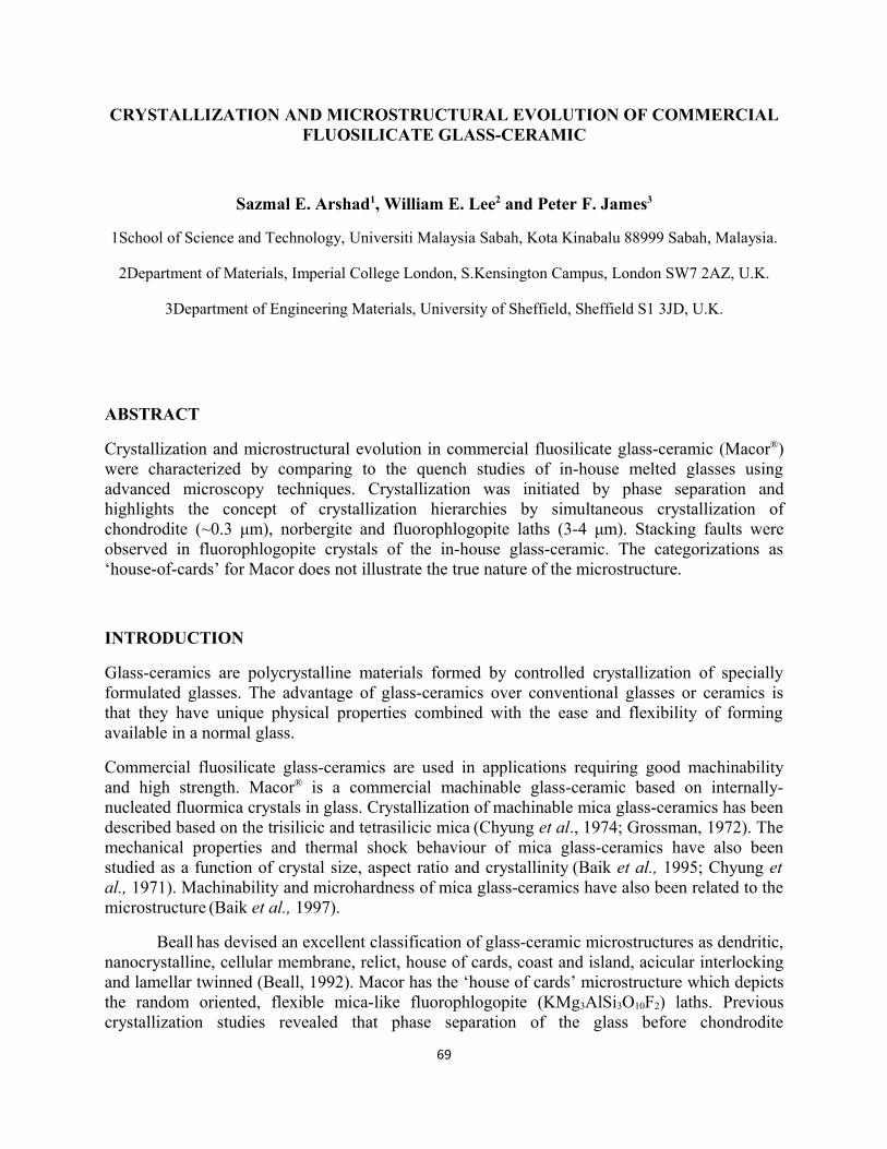
CRYSTALLIZATION AND MICROSTRUCTURAL EVOLUTION OF COMMERCIAL FLUOSILICATE GLASS-CERAMIC Sazmal E. Arshad 1 , William E. Lee 2 and Peter F. James 3 1School of Science and Technology, Universiti Malaysia Sabah, Kota Kinabalu 88999 Sabah, Malaysia. 2Department of Materials, Imperial College London, S.Kensington Campus, London SW7 2AZ, U.K. 3Department of Engineering Materials, University of Sheffield, Sheffield S1 3JD, U.K. ABSTRACT Crystallization and microstructural evolution in commercial fluosilicate glass-ceramic (Macor ® ) were characterized by comparing to the quench studies of in-house melted glasses using advanced microscopy techniques. Crystallization was initiated by phase separation and highlights the concept of crystallization hierarchies by simultaneous crystallization of chondrodite (~0.3 μm), norbergite and fluorophlogopite laths (3-4 μm). Stacking faults were observed in fluorophlogopite crystals of the in-house glass-ceramic. The categorizations as ‘house-of-cards’ for Macor does not illustrate the true nature of the microstructure. INTRODUCTION Glass-ceramics are polycrystalline materials formed by controlled crystallization of specially formulated glasses. The advantage of glass-ceramics over conventional glasses or ceramics is that they have unique physical properties combined with the ease and flexibility of forming available in a normal glass. Commercial fluosilicate glass-ceramics are used in applications requiring good machinability and high strength. Macor ® is a commercial machinable glass-ceramic based on internally- nucleated fluormica crystals in glass. Crystallization of machinable mica glass-ceramics has been described based on the trisilicic and tetrasilicic mica (Chyung et al., 1974; Grossman, 1972). The mechanical properties and thermal shock behaviour of mica glass-ceramics have also been studied as a function of crystal size, aspect ratio and crystallinity (Baik et al., 1995; Chyung et al., 1971). Machinability and microhardness of mica glass-ceramics have also been related to the microstructure (Baik et al., 1997). Beall has devised an excellent classification of glass-ceramic microstructures as dendritic, nanocrystalline, cellular membrane, relict, house of cards, coast and island, acicular interlocking and lamellar twinned (Beall, 1992). Macor has the ‘house of cards’ microstructure which depicts the random oriented, flexible mica-like fluorophlogopite (KMg 3 AlSi 3 O 10 F 2 ) laths. Previous crystallization studies revealed that phase separation of the glass before chondrodite 69
Transcript of Crystallization and Microstructural Evolution of ... · PDF fileCRYSTALLIZATION AND...
CRYSTALLIZATION AND MICROSTRUCTURAL EVOLUTION OF COMMERCIAL FLUOSILICATE GLASS-CERAMIC
Sazmal E. Arshad1, William E. Lee2 and Peter F. James3
1School of Science and Technology, Universiti Malaysia Sabah, Kota Kinabalu 88999 Sabah, Malaysia.
2Department of Materials, Imperial College London, S.Kensington Campus, London SW7 2AZ, U.K.
3Department of Engineering Materials, University of Sheffield, Sheffield S1 3JD, U.K.
ABSTRACT
Crystallization and microstructural evolution in commercial fluosilicate glass-ceramic (Macor®) were characterized by comparing to the quench studies of in-house melted glasses using advanced microscopy techniques. Crystallization was initiated by phase separation and highlights the concept of crystallization hierarchies by simultaneous crystallization of chondrodite (~0.3 μm), norbergite and fluorophlogopite laths (3-4 μm). Stacking faults were observed in fluorophlogopite crystals of the in-house glass-ceramic. The categorizations as ‘house-of-cards’ for Macor does not illustrate the true nature of the microstructure.
INTRODUCTION
Glass-ceramics are polycrystalline materials formed by controlled crystallization of specially formulated glasses. The advantage of glass-ceramics over conventional glasses or ceramics is that they have unique physical properties combined with the ease and flexibility of forming available in a normal glass.
Commercial fluosilicate glass-ceramics are used in applications requiring good machinability and high strength. Macor® is a commercial machinable glass-ceramic based on internally-nucleated fluormica crystals in glass. Crystallization of machinable mica glass-ceramics has been described based on the trisilicic and tetrasilicic mica (Chyung et al., 1974; Grossman, 1972). The mechanical properties and thermal shock behaviour of mica glass-ceramics have also been studied as a function of crystal size, aspect ratio and crystallinity (Baik et al., 1995; Chyung et al., 1971). Machinability and microhardness of mica glass-ceramics have also been related to the microstructure (Baik et al., 1997).
Beall has devised an excellent classification of glass-ceramic microstructures as dendritic, nanocrystalline, cellular membrane, relict, house of cards, coast and island, acicular interlocking and lamellar twinned (Beall, 1992). Macor has the ‘house of cards’ microstructure which depicts the random oriented, flexible mica-like fluorophlogopite (KMg3AlSi3O10F2) laths. Previous crystallization studies revealed that phase separation of the glass before chondrodite
69
(2Mg2SiO4.MgF2) nucleation followed by norbergite (Mg2Al4Si5O18) and finally massive
formation of interlocking fluorophlogopite laths (Chyung et al., 1974).
Characterizations were carried out in order to further understand the microstructural characteristics and crystal evolution in Macor with comparison made to the in-house glass-ceramics based on the commercial composition subjected to the two step heat-treatment.
EXPERIMENTAL PROCEDURES
Macor was supplied by Corning Incorporated (New York) and its composition was used as the basis for the in-house batches. The raw materials used in preparing in-house Macor glass composition were Loch Aline silica sand and reagent grade (supplied by Sigma-Aldrich Co. Ltd., Gillingham, U.K.) aluminium hydroxide Al(OH)3, magnesium hydroxide Mg(OH)2, potassium carbonate K2CO3, boric acid H3BO3 and magnesium fluoride MgF3 (Table 1). Glass melting was performed in Pt crucibles using electric furnace at 1450oC for 4 h. Stirring was initiated after 1 h using platinum blades at speed of 60 rpm for 3 h. The melts were then poured onto steel plates as circular patties. The opaque glass patties were then immediately transferred to an annealing furnace held at 550oC and held for 1 h followed by cooling rate of ~5oC/min to room temperature. The glasses were heat treated isothermally at 650, 750 and 850oC with a hold time of 1 h at each temperature and at 950oC held for 4 h. A two-step heat treatment based on the commercial regimes was also conducted in which the glass was heated to 700oC and held for 2 h before increasing to 950oC and holding for 4 h followed by cooling. The heating and cooling rates in all cases were approximately 5oC/min.
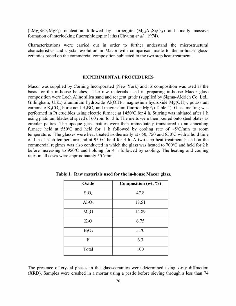
Table 1. Raw materials used for the in-house Macor glass.
Oxide Composition (wt. %)
SiO2 47.8
Al2O3 18.51
MgO 14.89
K2O 6.75
B2O3 5.70
F 6.3
Total 100
The presence of crystal phases in the glass-ceramics were determined using x-ray diffraction (XRD). Samples were crushed in a mortar using a pestle before sieving through a less than 74
70
um mesh sieve. The XRD (PW1730/10 Phillips Holland) used CuKα radiation and was operated at 50kV and 30 mA. Scanning was from 5 to 70o 2θ with a step size of 0.02 and scanning speed of 2o/min. Data analysis was performed using a computer running Sietronics XRD Trace Processing Software (version 2.0, © Sietronics Pty. Ltd., Belconnen Australia) and STOE WinXPOW software (version 1.06, © STOE & Cie GmbH, Hilpertstr. 10, D 64295, Darmstadt). Determination of the extent of crystallization was carried using Ohlberg and Strickler method with the modifications of Kim et al.(1989). Table 2 lists the ICDD cards used to identify phases.
Table 2. ICDD cards used in identification of crystal phasesCrystal phase Crystal system Space
groupJCPDS
Chondrodite(Mg,Fe)5(SiO4)2(F,OH)2
Monoclinic P21/a 12-257
Norbergite(Mg2SiO4⋅MgF2)
Orthorhombic Pnma 11-686
Fluorophlogopite (KMg3Al2Si3O10F2)
Monoclinic C2/m 76-816
Magnesium fluoride(MgF2)
Cubic Pa3 38-882
Samples were prepared for microscopy using standard ceramographic cutting, grinding, and polishing techniques. Optical microscopy was performed using a Reichert-Jung Polyvar microscope (Leica Microsystems GmbH, Wetzlar, Germany). Samples were gold-coated for reflected light examination to reduce internal scattering. Scanning electron microscopy (SEM) was performed on a Camscan Series 2 unit fitted with a Link AN10000 EDS unit. Samples were polished, HF etched and gold- or carbon-coated to avoid charging effects. Both secondary electron (SEI) and backscattered electron (BEI) imaging modes were used. Transmission electron microscopy (TEM) was on Phillips EM420 unit fitted with a Link eXL EDS detector operated in bright-field (BF) imaging mode at 120 kV.
RESULTS AND DISCUSSION
XRD revealed that the phases in commercial Macor are fluorophlogopite (KMg3AlSi3O10F2), mullite (3Al2O3
.2SiO2), magnesium fluoride (MgF2) and a significant amount of glass. Quantitative XRD revealed that the crystalline and amorphous phase contents were 37 and 63 weight percent respectively (Arshad et al., 2002).
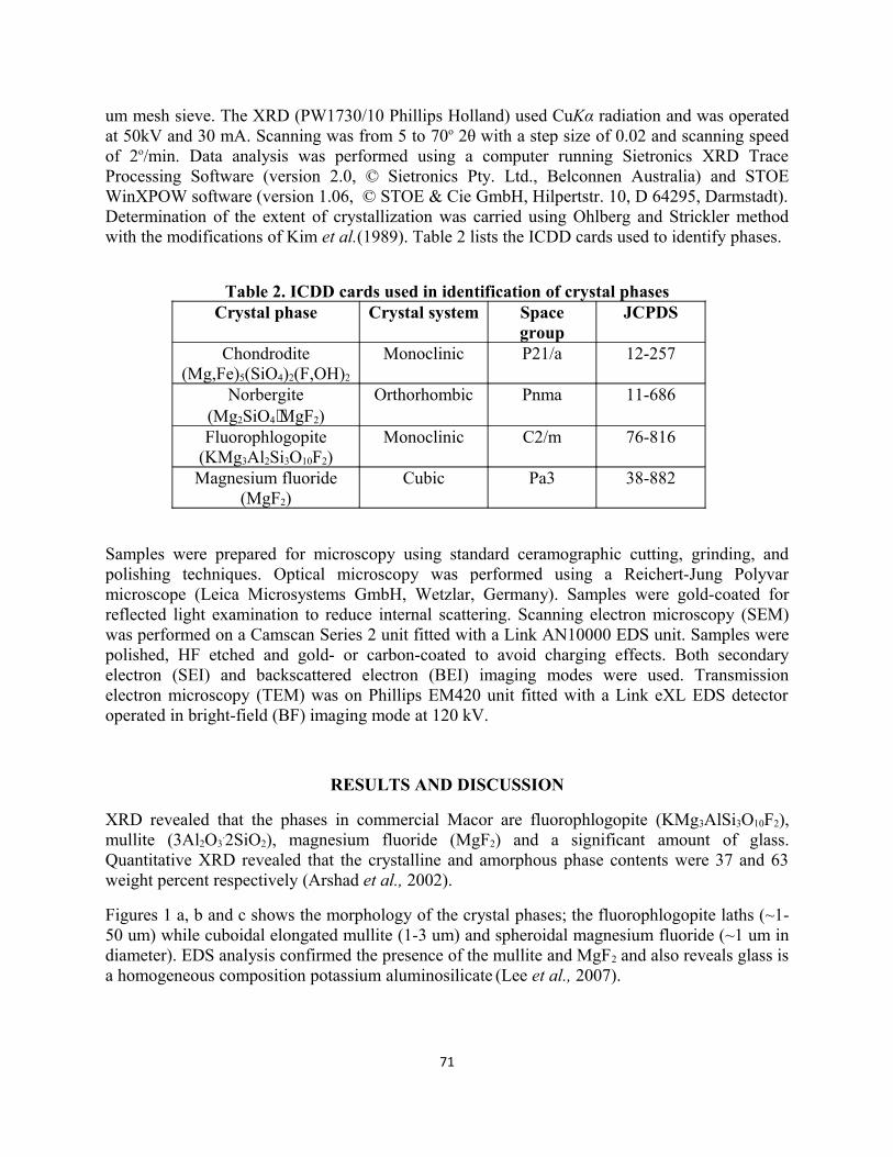
Figures 1 a, b and c shows the morphology of the crystal phases; the fluorophlogopite laths (~1-50 um) while cuboidal elongated mullite (1-3 um) and spheroidal magnesium fluoride (~1 um in diameter). EDS analysis confirmed the presence of the mullite and MgF2 and also reveals glass is a homogeneous composition potassium aluminosilicate (Lee et al., 2007).
71
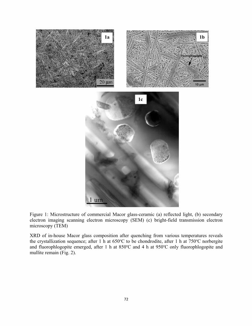
Figure 1: Microstructure of commercial Macor glass-ceramic (a) reflected light, (b) secondary electron imaging scanning electron microscopy (SEM) (c) bright-field transmission electron microscopy (TEM)
XRD of in-house Macor glass composition after quenching from various temperatures reveals the crystallization sequence; after 1 h at 650oC to be chondrodite, after 1 h at 750oC norbergite and fluorophlogopite emerged, after 1 h at 850oC and 4 h at 950oC only fluorophlogopite and mullite remain (Fig. 2).
72
1a 1b
1c
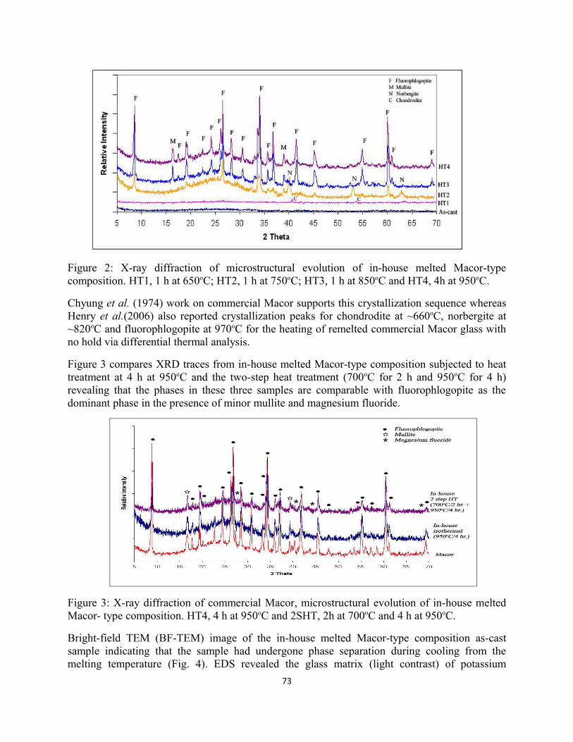
Figure 2: X-ray diffraction of microstructural evolution of in-house melted Macor-type composition. HT1, 1 h at 650oC; HT2, 1 h at 750oC; HT3, 1 h at 850oC and HT4, 4h at 950oC.
Chyung et al. (1974) work on commercial Macor supports this crystallization sequence whereas Henry et al.(2006) also reported crystallization peaks for chondrodite at ~660oC, norbergite at ~820oC and fluorophlogopite at 970oC for the heating of remelted commercial Macor glass with no hold via differential thermal analysis.
Figure 3 compares XRD traces from in-house melted Macor-type composition subjected to heat treatment at 4 h at 950oC and the two-step heat treatment (700oC for 2 h and 950oC for 4 h) revealing that the phases in these three samples are comparable with fluorophlogopite as the dominant phase in the presence of minor mullite and magnesium fluoride.
Figure 3: X-ray diffraction of commercial Macor, microstructural evolution of in-house melted Macor- type composition. HT4, 4 h at 950oC and 2SHT, 2h at 700oC and 4 h at 950oC.
Bright-field TEM (BF-TEM) image of the in-house melted Macor-type composition as-cast sample indicating that the sample had undergone phase separation during cooling from the melting temperature (Fig. 4). EDS revealed the glass matrix (light contrast) of potassium
73
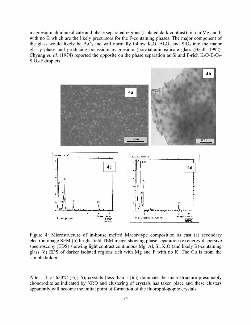
magnesium aluminosilicate and phase separated regions (isolated dark contrast) rich in Mg and F with no K which are the likely precursors for the F-containing phases. The major component of the glass would likely be B2O3 and will normally follow K2O, Al2O3 and SiO2 into the major glassy phase and producing potassium magnesium (boro)aluminosilicate glass (Beall, 1992). Chyung et. al. (1974) reported the opposite on the phase separation as Si and F-rich K2O-B2O3-SiO2-F droplets.
Figure 4: Microstructure of in-house melted Macor-type composition as cast (a) secondary electron image SEM (b) bright-field TEM image showing phase separation (c) energy dispersive spectroscopy (EDS) showing light contrast continuous Mg, Al, Si, K,O (and likely B)-containing glass (d) EDS of darker isolated regions rich with Mg and F with no K. The Cu is from the sample holder.
After 1 h at 650oC (Fig. 5), crystals (less than 1 µm) dominate the microstructure presumably chondrodite as indicated by XRD and clustering of crystals has taken place and these clusters apparently will become the initial point of formation of the fluorophlogopite crystals.
74
4a
4b
4c 4d
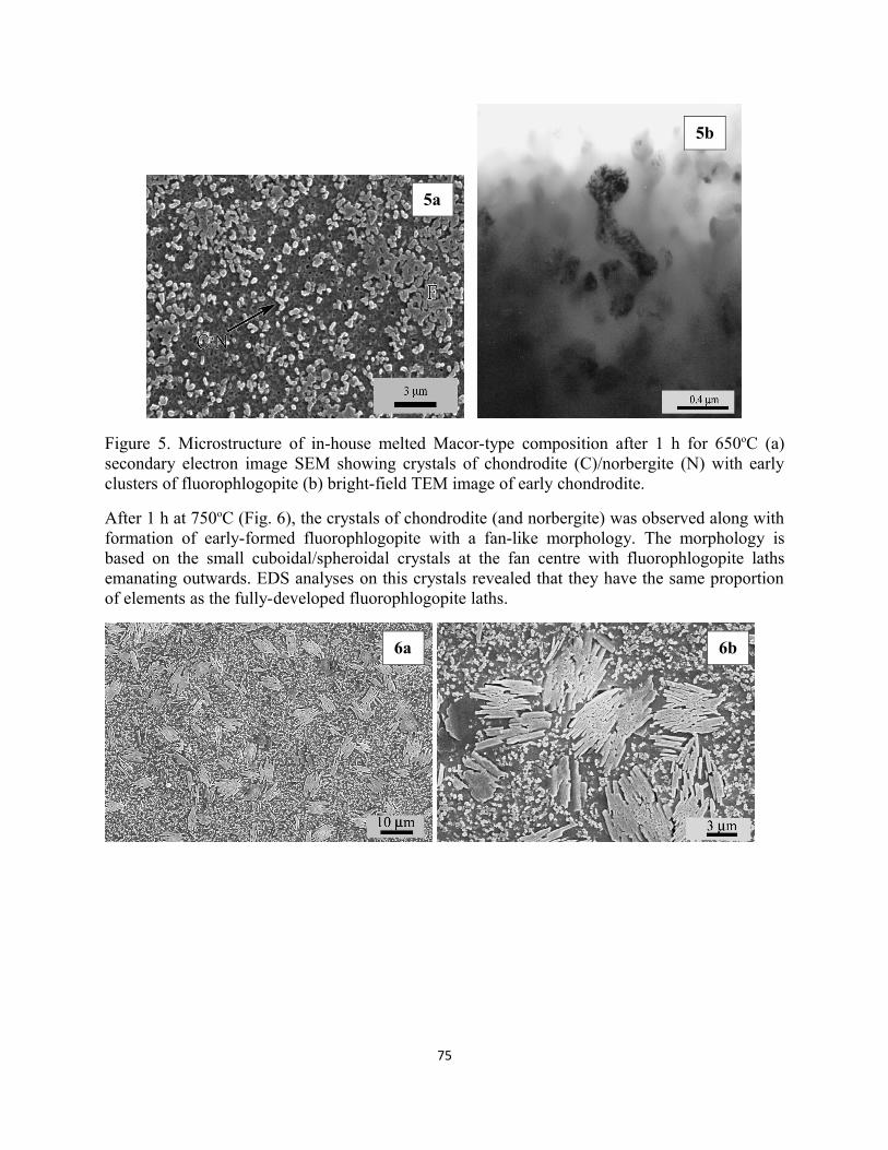
Figure 5. Microstructure of in-house melted Macor-type composition after 1 h for 650oC (a) secondary electron image SEM showing crystals of chondrodite (C)/norbergite (N) with early clusters of fluorophlogopite (b) bright-field TEM image of early chondrodite.
After 1 h at 750oC (Fig. 6), the crystals of chondrodite (and norbergite) was observed along with formation of early-formed fluorophlogopite with a fan-like morphology. The morphology is based on the small cuboidal/spheroidal crystals at the fan centre with fluorophlogopite laths emanating outwards. EDS analyses on this crystals revealed that they have the same proportion of elements as the fully-developed fluorophlogopite laths.
75
5a
5b
6a 6b
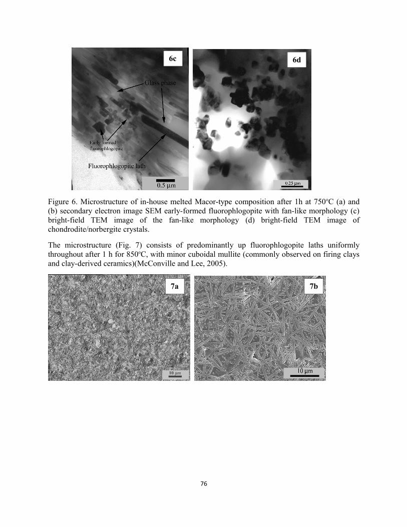
Figure 6. Microstructure of in-house melted Macor-type composition after 1h at 750oC (a) and (b) secondary electron image SEM early-formed fluorophlogopite with fan-like morphology (c) bright-field TEM image of the fan-like morphology (d) bright-field TEM image of chondrodite/norbergite crystals.
The microstructure (Fig. 7) consists of predominantly up fluorophlogopite laths uniformly throughout after 1 h for 850oC, with minor cuboidal mullite (commonly observed on firing clays and clay-derived ceramics)(McConville and Lee, 2005).
76
6c 6d
7a 7b
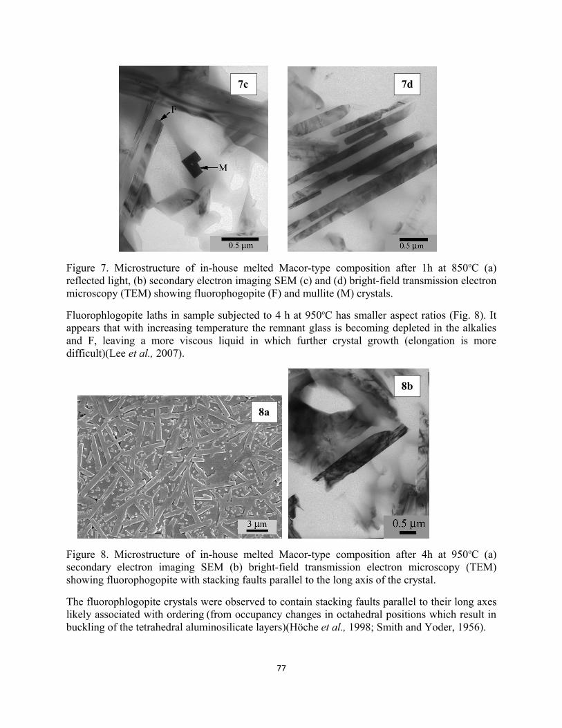
Figure 7. Microstructure of in-house melted Macor-type composition after 1h at 850oC (a) reflected light, (b) secondary electron imaging SEM (c) and (d) bright-field transmission electron microscopy (TEM) showing fluorophogopite (F) and mullite (M) crystals.
Fluorophlogopite laths in sample subjected to 4 h at 950oC has smaller aspect ratios (Fig. 8). It appears that with increasing temperature the remnant glass is becoming depleted in the alkalies and F, leaving a more viscous liquid in which further crystal growth (elongation is more difficult)(Lee et al., 2007).
Figure 8. Microstructure of in-house melted Macor-type composition after 4h at 950oC (a) secondary electron imaging SEM (b) bright-field transmission electron microscopy (TEM) showing fluorophogopite with stacking faults parallel to the long axis of the crystal.
The fluorophlogopite crystals were observed to contain stacking faults parallel to their long axes likely associated with ordering (from occupancy changes in octahedral positions which result in buckling of the tetrahedral aluminosilicate layers)(Höche et al., 1998; Smith and Yoder, 1956).
77
7c 7d
8a
8b
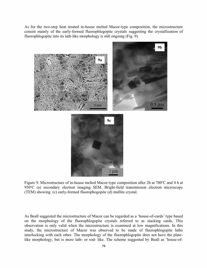
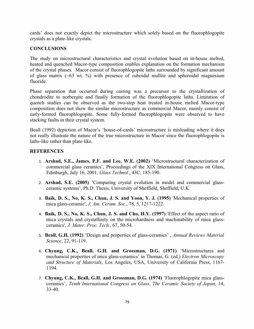
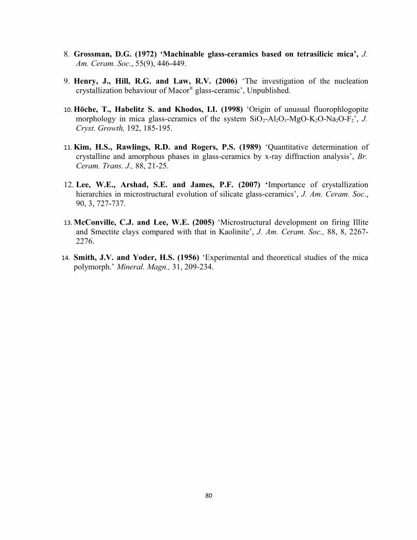
As for the two-step heat treated in-house melted Macor-type composition, the microstructure consist mainly of the early-formed fluorophlogopite crystals suggesting the crystallization of fluorophlogopite into its lath-like morphology is still ongoing (Fig. 9).
Figure 9. Microstructure of in-house melted Macor-type composition after 2h at 700oC and 4 h at 950oC (a) secondary electron imaging SEM. Bright-field transmission electron microscopy (TEM) showing (c) early-formed fluorophogopite (d) mullite crystal.
As Beall suggested the microstructure of Macor can be regarded as a ‘house-of-cards’ type based on the morphology of the fluorophlogopite crystals referred to as stacking cards. This observation is only valid when the microstructure is examined at low magnifications. In this study, the microstructure of Macor was observed to be made of fluorophlogopite laths interlocking with each other. The morphology of the fluorophlogopite does not have the plate-like morphology, but is more lath- or rod- like. The scheme suggested by Beall as ‘house-of-
78
9a
9b
9c
cards’ does not exactly depict the microstructure which solely based on the fluorophlogopite crystals as a plate-like crystals.
CONCLUSIONS
The study on microstructural characteristics and crystal evolution based on in-house melted, heated and quenched Macor-type composition enables explanation on the formation mechanism of the crystal phases. Macor consist of fluorophlogopite laths surrounded by significant amount of glass matrix (~63 wt. %) with presence of cuboidal mullite and spheroidal magnesium fluoride.
Phase separation that occurred during casting was a precursor to the crystallization of chondrodite to norbergite and finally formation of the fluorophlogopite laths. Limitation of quench studies can be observed as the two-step heat treated in-house melted Macor-type composition does not show the similar microstructure as commercial Macor, mainly consist of early-formed fluorophlogopite. Some fully-formed fluorophlogopite were observed to have stacking faults in their crystal system.
Beall (1992) depiction of Macor’s ‘house-of-cards’ microstructure is misleading where it does not really illustrate the nature of the true microstructure in Macor since the fluorophlogopite is laths-like rather than plate-like.
REFERENCES
1. Arshad, S.E., James, P.F. and Lee, W.E. (2002) ‘Microstructural characterization of commercial glass ceramics’, Proceedings of the XIX International Congress on Glass, Edinburgh, July 16, 2001, Glass Technol., 43C, 185-190.
2. Arshad, S.E. (2005) ‘Comparing crystal evolution in model and commercial glass-ceramic systems’, Ph.D. Thesis, University of Sheffield, Sheffield, U.K.
3. Baik, D. S., No, K. S., Chun, J. S. and Yoon, Y. J. (1995) 'Mechanical properties of mica glass-ceramic', J. Am. Ceram. Soc., 78, 5, 1217-1222.
4. Baik, D. S., No, K. S., Chun, J. S. and Cho, H.Y. (1997) 'Effect of the aspect ratio of mica crystals and crystallinity on the microhardness and machinability of mica glass-ceramics', J. Mater. Proc. Tech., 67, 50-54.
5. Beall, G.H. (1992) ‘Design and properties of glass-ceramics’ , Annual Reviews Material Science, 22, 91-119.
6. Chyung, C.K., Beall, G.H. and Grossman, D.G. (1971) ‘Microstructures and mechanical properties of mica glass-ceramics’ in Thomas, G. (ed.) Electron Microscopy and Structure of Materials, Los Angeles, USA, University of California Press, 1167-1194.
7. Chyung, C.K., Beall, G.H. and Grossman, D.G. (1974) ‘Fluorophlogopite mica glass-ceramics’, Tenth International Congress on Glass, The Ceramic Society of Japan, 14, 33-40.
79
8. Grossman, D.G. (1972) ‘Machinable glass-ceramics based on tetrasilicic mica’, J. Am. Ceram. Soc., 55(9), 446-449.
9. Henry, J., Hill, R.G. and Law, R.V. (2006) ‘The investigation of the nucleation crystallization behaviour of Macor® glass-ceramic’, Unpublished.
10. Höche, T., Habelitz S. and Khodos, I.I. (1998) ‘Origin of unusual fluorophlogopite morphology in mica glass-ceramics of the system SiO2-Al2O3-MgO-K2O-Na2O-F2’, J. Cryst. Growth, 192, 185-195.
11.Kim, H.S., Rawlings, R.D. and Rogers, P.S. (1989) ‘Quantitative determination of crystalline and amorphous phases in glass-ceramics by x-ray diffraction analysis’, Br. Ceram. Trans. J., 88, 21-25.
12. Lee, W.E., Arshad, S.E. and James, P.F. (2007) ‘Importance of crystallization hierarchies in microstructural evolution of silicate glass-ceramics’, J. Am. Ceram. Soc., 90, 3, 727-737.
13.McConville, C.J. and Lee, W.E. (2005) ‘Microstructural development on firing Illite and Smectite clays compared with that in Kaolinite’, J. Am. Ceram. Soc., 88, 8, 2267-2276.
14. Smith, J.V. and Yoder, H.S. (1956) ‘Experimental and theoretical studies of the mica polymorph.’ Mineral. Magn., 31, 209-234.
80