Crystal Water/Aqua Clean - Best Buy Pool Supply LLC
11
OWNER'S GUIDE INSTALLATION INSTRUCTIONS General Description Your Crystal Water/Aqua Clean D.E. Filter combines superior water filtration with ease of operating and totally corrosion-free construc- tion. it uses diatomaceous earth (D.E.) which is the most efficient dirt remover and filter medium known. The D.E. is fed through the skimmer at initial start-up, it uniformly coats the curved vertical filter elements which are covered with a custom fitted monofilament polypropylene filter cloth. As pool water is pumped through the Slide Valve (Optional) into the bottom of the filter tank, the D.E. coats the filter grids and filters out even the most minute particles resulting in clear, clean, sparkling water. After a period of time, the accumulated dirt in the filter causes a resistance to flow, the pressure rises, and flow diminishes. This means the dirt holding capacity of the D.E. has been reached, and it is time to clean (backwash) your filter. With the Slide Valve (Optional) in the backwash position, the water is automatically reversed through the filter, flushing the trapped dirt, debris and D.E. out the waste line. Once the filter is backwashed (cleaned) of D.E. and dirt, the Slide Valve (Optional) is manually re-sequenced to filter position and a fresh charge of D.E. is added to resume normal filtering. IMPORTANT SAFETY INSTRUCTIONS READ AND FOLLOW ALL INSTRUCTIONS A) Carefully read and follow all instructions. B) When installing and using this equipment, basic safety precau- tions must always be followed. This filter operates under high pressure. failure to follow instructions may result in serious injury. C) Make sure clamp is located properly over the filter flange. The clamp must be tightened firmly and evenly until spring coils touch each other (See illustration step. 22, page 6.) D) CAUTION: All suction and discharge valves must be open when starting the system. Failure to do so could result in severe personal injury and/ or property damage. CAUTION: We strongly recommend having a qualified pro- fessional install this product. CRYSTAL WATER/AQUA CLEAN D.E. FILTER SYSTEM OWNER'S MANUAL INSTALLATION INSTRUCTIONS Crystal Water/Aqua Clean D.E. Filter System 810-0131-ENG
Transcript of Crystal Water/Aqua Clean - Best Buy Pool Supply LLC

OWNER'SGUIDEINSTALLATIONINSTRUCTIONS
General DescriptionYour Crystal Water/Aqua Clean D.E. Filter combines superior waterfiltration with ease of operating and totally corrosion-free construc-tion. it uses diatomaceous earth (D.E.) which is the most efficient dirtremover and filter medium known.The D.E. is fed through the skimmer at initial start-up, it uniformlycoats the curved vertical filter elements which are covered with acustom fitted monofilament polypropylene filter cloth. As pool wateris pumped through the Slide Valve (Optional) into the bottom of thefilter tank, the D.E. coats the filter grids and filters out even the mostminute particles resulting in clear, clean, sparkling water. After a period of time, the accumulated dirt in the filter causes aresistance to flow, the pressure rises, and flow diminishes. Thismeans the dirt holding capacity of the D.E. has been reached, and itis time to clean (backwash) your filter. With the Slide Valve (Optional)in the backwash position, the water is automatically reversedthrough the filter, flushing the trapped dirt, debris and D.E. out thewaste line. Once the filter is backwashed (cleaned) of D.E. and dirt,the Slide Valve (Optional) is manually re-sequenced to filter positionand a fresh charge of D.E. is added to resume normal filtering.
IMPORTANT SAFETY INSTRUCTIONSREAD AND FOLLOW ALL INSTRUCTIONSA) Carefully read and follow all instructions. B) When installing and using this equipment, basic safety precau-
tions must always be followed. This filter operates under highpressure. failure to follow instructions may result in serious injury.
C) Make sure clamp is located properly over the filter flange. Theclamp must be tightened firmly and evenly until spring coils toucheach other (See illustration step. 22, page 6.)
D) CAUTION: All suction and discharge valves must be openwhen starting the system. Failure to do so could result insevere personal injury and/ or property damage.
CAUTION: We strongly recommend having a qualified pro-fessional install this product.
CRYSTAL WATER/AQUA CLEAN D.E. FILTER SYSTEMOWNER'S MANUAL
INSTALLATION INSTRUCTIONS
Crystal Water/Aqua CleanD.E. Filter System
810-0131-ENG

1. INSTALLATION:Pump Selection and Location:To power your filter, select a continuous duty pump designed forswimming pool or spa service.It is important to first determine where your pump and filter willbe located. If above the water line, a self-priming pump such asWorkman, SVL56 or the Mustang have the ability to lift waterfrom a lower level and prime automatically.Select a pump with an average output range suitable for the fil-ters capacity. Other considerations are operation of hydrothera-py fittings, automatic cleaners, etc. Your dealer will help youselect the proper size pump for your system.
2. FILTER LOCATION:
Since plumbing fittings offer a resistance to water flow, positionthe filter as close to the swimming pool as practical. Keep thenumber of fittings to a minimum. Select a well-drained area, onethat will not flood when it rains. The filter should be placed on alevel concrete slab, very firm ground or equivalent, as recom-mended by your pool dealer. Allow for minimum top and sideclearances as per chart. Be sure filter, pump, drain and pressuregauge are accessible for convenient operation.
Position filter so the tank can drain away from pool and buildingsby gravity.
If practical, place pump and filter in the shade to shield it fromcontinuous direct heat from sun.
3. PLUMBING: Use 11/2″ , 2″ or 21/2″ piping. Connections are slip sockets(solvent weld).
4. Ball or gate valves are recommended where needed. While allsystems vary, the main consideration is to provide the desiredcontrol of water flow from the pool to the pump, filter and backto the pool. When the filter is located below the water level, pro-vide valves to prevent back flow of water to the filter duringcleaning and routine servicing.
5. Assemble Waterway Slide Valve (Optional) to filter. Lubricate the O-Rings first (We recommend using silicone lubricant). Align the twovalve pipe connections, O-Rings in place, with the two openings inthe side of the filter tank and press in firmly. Secure the assemblyto the tank connections with the two bulkhead lock nuts. Do Not Over-Tighten.
O-Rings(Inside Union Nuts)
SILI
CONE
ATop
Clearance
BSide
Clearance
IN. IN.CM CMModel No.
570-0024 5 13 6 16
570-0036 11 28 6 16
570-0048 17 43 6 16
570-0060 23 58 6 16
A
B
WorkMan
Gate Valve
Ball Valve
SVL56
Mustang
1

8. All electrical connections should be made in accordance with alllocal codes.
9. CAUTION: ANSI/NSPI-4 Article V, standard for in-groundpools, advises that components such as the filtration system,pumps and heater be positioned so as to prevent access byyoung children.
7. A filter drain plug is furnished with each filter and is all that isneeded for complete filter draining. A Manual Air Valve (MAR) isfurnished to aid in bleeding unwanted air when starting the filter.The internal auto air vent provides air removal during operation.
6. Connect the pool skimmer(s) and main drain(s) to the inlet andthe return lines to the outlet of the Slide Valve (Optional). Alwaysuse two or more drains per pump.
If the pressure gauge is not already installed, apply Teflon tape tothe gauge threads on the Manual Air Relief Valve (MAR), andcarefully screw the gauge into the gauge adapter assembly. Do Not Over Tighten.
Drain Plug
MAR
ELECTRICALCODE
NORMATIVAELECTRICA
2

MAR
FilterClamp
DrainPlug
12. INITIAL START-UP OF THE FILTER:Make sure Filter Clamp and MAR are secure. Be sure FilterDrain Plug is closed. Open Manual Air Vent Screw at the side ofMAR a few turns. Set filter Slide Valve (Optional) to filter posi-tion (See step 10, page 3). Open suction and return valves(when used).Follow the manufacturer's instructions to prime and start thepump. Air in the system will vent out of the Air Relief Valve.Close Manual Air Vent Screw when a steady stream of wateremerges. When a steady flow of water returns to the pool, D.E.should now be added to the filter. DO NOT operate the filter formore than 5 or 6 minutes without the D.E., (DiatomaceousEarth) to avoid damaging the grid elements.
13. ADDING DIATOMACEOUS EARTH (D.E.):Add the correct amount of D.E. (see specifications on the filter label)into the system through the skimmer at a slow even pace. Record thepressure gauge reading after the diatomaceous earth (D.E.) has beenadded. This is the start (clean) pressure.
SKIMMER
Diatom
aceou
sEa
rthD.E
.
Filter Pool
11. OPERATION:Before Starting the Filter:Obtain a supply of operating chemicals, D.E., and a pool testkit. Use only swimming pool grade D.E. Balance the pool waterby adding chemicals in accordance with the instructions pro-vided by the chemicals’ manufacturer.
10. TWO-POSITION SLIDE VALVE (Optional):
(A) FILTER: Set Valve to Filter for normal filtering. Also use forvacuuming (Handle in Down Position.)
(B) BACKWASH: For cleaning filter (Handle in Up Position.)
BACKWASHPOSITION
FILTERPOSITION
A B
3

16. DISASSEMBLY:Shut off the pump then use a 9/16″ deep socket and ratchet(1) to loosen Spring Barrel Assembly, next use Starter Wrench(2) provided, to completely remove Spring Barrel Assembly.Place clamp assembly out of the way in a convenient place (3).You can now easily remove the filter lid, exposing the dirtyelement assembly.
Damage to clamp may lead to system failure.
12
3
MAR
15. BACKWASHING (CLEANING) THE FILTER:
(A) Shut off the pump set filter Slide Valve (Optional) to backwash.Set valve to UP position for backwashing.
Important: To prevent unnecessary strain on piping systemand valves, always shut off pump before switching filterSlide Valve (Optional) positions.
(B) Start pump and backwash for approximately two to five min-utes, or until water out waste line appears clean.
(C) Shut off pump and set valve to down position for filter.
Proceed as in ADDING DIATOMACEOUS EARTH (D.E.)described in step 13, page 3.
(UP)BACKWASHPOSITION(DOWN)
FILTERPOSITION
14. PRESSURE GAUGEFiltration starts as soon as D.E. has been added to the filter. Asthe filter removes dirt from the pool water, the accumulated dirtcauses a resistance to flow. As a result, the pressure gauge willrise and the water flow will decrease. When the pressure rises8-10 psi above the start (clean) pressure, it is time to backwash(clean) the filter. NOTE: During initial clean-up of the pool,particularly with a new pool or a very dirty pool, it may benecessary to backwash more frequently due to the unusu-ally heavy initial dirt load in the water.
4
17. INITIAL CLEANING:We recommend hosing down the element cluster assemblywith a strong stream from a garden hose. Be sure to removedrain plug and/or open any valves on drain port. Remove asmuch of the dirty D.E. and accumulated debris by flushing itout of the drain opening. This will allow for easier removal ofthe element cluster assembly.

19. Place The Grid Element Cluster on the ground. Thoroughly hoseoff the remaining dirty D.E. and debris.
18. REMOVING GRID ELEMENT:Rock the element cluster assembly slightly from side to sideto free the manifold from the vertical outlet elbow. The gridelement cluster assembly may now be removed by lifting itstraight up using the lift handles.
5
20. REASSEMBLY:(A) Lubricate Outlet Elbow Assembly O-Ring with siliconelubricate.(B) Replace D.E. Manifold Assembly into filter tank, carefully fit-ting the Manifold Assembly over Outlet Elbow O-Ring.
O-RingSILICONE
D.E. Manifold Assembly
Outlet ElbowAssembly

21. REINSTALL TANK LID:Clean and lightly lubricate O-Ring with silicone lubricant andcarefully place over bottom filter body lip.Clean O-Ring flange sealing surface on filter lid and place overbottom tank O-Ring, pressing down firmly and evenly to seat thefilter lid in place.
2
3
1
Detail
Spring BarrelNut Assembly
On Threaded T-Bolt
T-Bolt
Trunnion
SpringBarrel Ass'y.
22. These instructions must be followed exactly to prevent thelid from blowing off during system startup.
1. Be certain the O-Ring is in position in the lower tank half.Place the filter lid over the lower tank half, sandwiching the O-Ring in between.
2. Holding the ends of the Filter Clamp apart, position the centersegment over both upper and lower tank half flanges. Bring the ends of the clamp together, while inserting T-boltinto the trunnion (3).
3. Place washer, tension-indicating spring (Spring BarrelAssembly) and nut on T-bolt (Detail), then hand tighten nutusing the Starter Wrench (1). Recheck filter clamp for properseating on tank flanges.
4. Begin to tighten nut using a 9/16″ deep socket and ratchet(2). While tightening the nut, tap all around outside of filterclamp with a mallet (or similar tool) to insure uniform loadingand proper seating of clamp. Continue tapping and tighteninguntil spring coils of the spring touch each other (4). Do nottighten beyond this point.
5. Check spring coils once per month to assure that they contin-ue to touch each other – if not, repeat step 4.
IMPORTANT: Be sure to tighten nut untilspring coils touch each other.
4
6
Drain Plug
MAR23. Install Drain Plug, open pool suction and return valves and pro-
ceed as in step 12, page 3, Initial Start-Up Of The Filter.
Filter Pool

BACKWASHPOSITION
FILTERPOSITION 25. WINTERIZING VALVE:
Slide Valve (Optional): Open waste line and raise valve tobackwash position. Note: Drain and winterize all equipmentaccording to instructions. Consult your retailer or service pro-fessional if you have any questions.
24. WINTERIZING:To winterize where sub-freezing temperatures can be expected,the filter should be drained. Remove the Drain Plug, backwashthe Filter, remove and clean the Filter Grids. Reinstall FilterGrids in Filter Tank.Be sure to remove the Drain Plug during the winter season toavoid cracking the Filter Tank.
7
NOTES:______________________________________________________________________________________________________________________________________________________________________________________________________________________________________________________________________________________________________________________________________________________________________________________________________________________________________________________________________________________________________________________________________________________________________________________________________________________________________________________________________________________________________________________________________________________________________________________________________________________________________________________________________________________________________________________________________________________________________________________________________________________________________________________________________________________________________________________________________________________________________________________________________________________________________________________________________________________________

98
11
14
12
15
13
76
10
17 16
1e1b
2
34
5
1d
1a
1c
11f
1h1g
18a18b
18c
18d18
1j1i
CRYSTAL WATER/AQUA CLEAR CARTRIDGE FILTERReplacement Parts Diagram
D.E. REPLACEMENT PARTS
ITEMPART NO. DESCRIPTION
1g 550-4240 Pressure Relief Valve Assembly1a 602-4211 Service Bezel1b 830-4200 Pressure Gauge1c 519-4281 Air Relief Body1d 805-0110 O-Ring1e 550-4230 Pressure Relief Screw with O-Ring1f 602-4201 Handle, Pressure Relief Valve1g 805-0233 O-Ring (2)1h 827-8150 Spring (Plunger) — 1.950″ Dia. x 1.600″ Dia. x 4.000″ Long1i 519-4370 Plunger1j 718-4200 Valve Nut2g 550-4450 36 Sq. Ft. Filter Lid w/DE Crystal Water/Aqua Clean Filter Labels
550-4430 48 Sq. Ft. Filter Lid w/DE Crystal Water/Aqua Clean Filter Labels550-4440 60 Sq. Ft. Filter Lid w/DE Crystal Water/Aqua Clean Filter Labels
3g 550-4260 Metal Clamp with Clamp Spring Assembly4g 550-4250 Clamp Spring Assembly and Wrench5g 805-0000 O-Ring Main Body6g 550-4320 Air Relief Assembly, 24, 36, 48 and 60 Sq. Ft. DE Filter7g 718-4320 Manifold Nut 8g 550-4200 DE Manifold Assembly with Air Relief Assembly9g 519-4270 Grid Alignment Template
10g 818-3940 DE Short Grid, 36 Sq. Ft.818-3900 DE Short Grid, 48 Sq. Ft.818-4000 DE Short Grid, 60 Sq. Ft.
11g 818-3950 DE Grid, 36 Sq. Ft.818-3910 DE Grid, 48 Sq. Ft.818-3930 DE Grid, 60 Sq. Ft.
12g 550-4380 DE Grid Support Ass'y W/20″ PVC Shaft – 36 Sq. Ft. Filter550-4310 DE Grid Support Ass'y W/26″ PVC Shaft – 48 Sq. Ft. Filter550-4350 DE Grid Support Ass'y W/32″ PVC Shaft – 60 Sq. Ft. Filter
13g 550-4390 21/2″ Outlet Elbow Ass'y – 36 Sq. Ft. DE Filter550-4220 21/2″ Outlet Elbow Ass'y – 48 Sq. Ft. DE Filter550-4210 21/2″ Outlet Elbow Ass'y – 60 Sq. Ft. DE Filter
14g 411-4200 Long Elbow Fitting 21/2″ Diameter15g 550-4280 Filter Body16g 805-0339 O-Ring (2)17g 419-4201 CPL, 21/2″ Thd – (2)18g 400-6600 Drain Elbow Ass'y w/Drain Plug – O-Rings & Base Fitting18a 215-4200 Base Wall Fitting18b 805-0229 O-Ring (2)18c 411-4201 2″ Drain Elbow18d 400-6651 2″ Plug Assembly with O-Ring
8

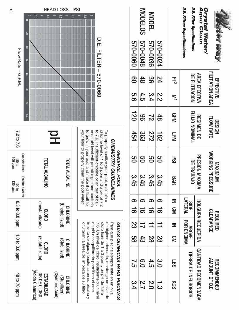
Important InformationRead and Follow All InstructionsAlgae is a form of plant life which can vary in size from a few thousandths of an inch to the size of a smalltree. Of the many forms of algae, the one most frequently found in the swimming pool water are micro-scopic in size and green in color.Algae readily grows in sunlight and can, under favorable conditions quickly overgrow a swimming poolturning it completely green in just a few hours. On the other hand, swimming pool water can be unfa-vorable to algae growth simply by maintaining a chlorine level of at least 1.0 ppm in the water at all times.The chlorine level should be checked at least once a week using a suitable test kit.If an algae condition develops and the pool water "blooms" green, superchlorination of the pool will benecessary to clear it. Add unstabilized granular chlorine, or liquid chlorine. Follow the chemical manufac-turer's recommendation for superchlorination. The algae will quickly become inactive and can then beremoved by the filter. Live algae, on the other hand, multiplies so fast that the filter cannot keep up withits growth rate.When correctly used, commercial algaecides are effective against algae, though algaecides should beused in conjunction with, and not as a substitute for, regular chlorination or superchlorination.Maintaining a chlorine level of at least 1.0 ppm in the pool water at all times is the most effective way toprevent algae growth in swimming pools.NOTE:Pure clear swimming pool water is the combination of two factors, adequate filtration and proper waterchemistry balance. One without the other will not give the clean, clear water you desire.Your filter system is designed for continuous operation. However, this is not necessary for most swim-ming pools. You can determine your filter operation schedule based on your pool size.To properly sanitize your pool, maintain a free chlorine level of 1 to 3 ppm and a pH level of 7.6 will helpin preventing algae and bacteria to grow in your pool and make it easier for your filter to properly cleanthe pool water.
SERVICE AND REPAIRSConsult your local authorized Waterway dealer or service center. No returns may be made directly to thefactory without the expressed written authorization of Waterway Plastics.
2200 East Sturgis Rd., Oxnard, California 93030805-981-0262 • FAX: 805-981-9403
E-mail: [email protected]
9
Flow
Rate – G
.P.M.
HEAD LOSS – PSI
D.E
. FILTE
R – 570-0060
54.5
43.5
32.5
21.5
10.5
00
2040
6080
100120
140
GE
NE
RA
L PO
OL
CH
EM
IST
RY
GU
IDE
LAIN
ES
To prop
erly sanitize your pool, m
aintain achlorine level of 1 to 3 p
pm
and a p
H of 7.2
to 7.6. Insufficient chlorine or an out of bal-
ance pH
level will p
ermit algae and
bacteria
to grow in your p
ool and m
ake it difficult for
your filter to prop
erly clean the pool w
ater.
GU
IAS
QU
IMIC
AS
PAR
A P
ISC
INA
SP
ara que p
iscina siemp
re este en un nivald
e higiene adecuad
o, mantenga un nivel d
ecloro lib
re de 1 a 3 p
pm
y un pH
de 7.2 a
7.6. Un nivel d
e cloro insuficiente o un niveld
e pH
deseq
uilibrad
o perm
itiran el crec-im
iento de algas y b
acterias en su piscina y
difultaran la tarea d
e limp
ieza de su filtro.
TOTAL ALKALINECHLORINE
CHLORINECHLORINE
(Unstabilized)(Stabilized)
(Stabilizer)(Cyanuric Acid)
pHTOTAL ALCALINO
CLOROCLORO
ESTABILIZAD(Inestabilizado)
(Estabilizado)OR DE CLORO
(Acida Cianurico)
Sunbelt AreasFrostbelt Areas
7.2 to 7.680 to
100 to0.3 to 3.0 ppm
1.0 to 3.0 ppm40 to 70 ppm
100 ppm130 ppm
EFFECTIVEDESIGN
MAXIM
UMREQUIRED
RECOMM
ENDEDFILTRATION AREA
FLOW RATE
WORKING PRESSURE
CLEARANCEAM
OUNT OF D.E.
AREA EFECTIVAREGIM
EN DEPRESION M
AXIMA
HOLGURA REQUERIDACANTIDAD RECOM
ENDADADE FILTRACION
FLUJO NOMINAL
DE TRABAJOSIDE
ABOVETIERRA DE INFUSORIOS
LATERALPOR ENCIM
A
FT2
M2
GPMLPM
PSIBAR
INCM
INCM
LBSKGS
570-002424
2.248
18250
3.456
1611
283.0
1.3M
ODEL570-0036
363.4
72272
503.45
616
1128
4.52.0
MODELOS
570-004848
4.596
36350
3.456
1617
436.0
2.7570-0060
605.6
120454
503.45
616
2358
7.53.4
Crysta
l Wa
ter/
Aq
ua
Cle
an
D.E. Filter Specifications
D.E. Filtroe Especificaciones
10