Crystal plasticity finite-element analysis versus … plasticity finite-element analysis versus...
11
Crystal plasticity finite-element analysis versus experimental results of pyramidal indentation into (0 0 1) fcc single crystal Bernhard Eidel ⇑ Interdisciplinary Centre for Advanced Materials Simulation (ICAMS), Ruhr-Universita ¨ t Bochum, Stiepeler Strasse 129, D-44801 Bochum, Germany Received 19 October 2010; accepted 17 November 2010 Available online 28 December 2010 Abstract Pyramidal microindentation into the (0 0 1) surface of an face-centered cubic (fcc) single crystal made of a Ni-base superalloy is ana- lyzed in experiment and crystal plasticity finite-element simulations. The resultant material pile-up at the surface reflects the material’s symmetry and turns out to be insensitive to different loading scenarios as induced by (i) different azimuthal orientations of the pyramidal indenter, (ii) different indenter shapes (sphere or pyramid) and (iii) the elastic anisotropy. Experiments and simulations are in agreement and suggest that pile-up deformation patterns merely depend on the geometry of discrete slip systems but are invariant to different aniso- tropic stress distributions as induced by (i)–(iii). The local adaption of pile-up to the pyramidal indenter leads to convex or concave indent shapes corresponding to the indenter orientation. We contrast the present findings for curved indent shapes of fcc single crystals to similar, well-known observations for quasi-isotropic polycrystals. Although phenomenologically similar in kind, the driving mecha- nisms are different: for the single crystal it is the discrete and anisotropic nature of plastic glide in certain slip systems; for isotropic poly- crystals it is the rate of strain-hardening caused by the cumulative response of dislocations. Ó 2010 Acta Materialia Inc. Published by Elsevier Ltd. All rights reserved. Keywords: Crystal plasticity; Micromechanical modeling; Indentation; Anisotropy; Ni alloys 1. Introduction Indentation into single-crystalline material has attracted interest in the experimental, modeling and computational branches of materials science for several reasons. One rea- son is that the simple, homogeneous microstructural com- position enables identification of elementary deformation mechanisms without the complexity of heterogeneous, polycrystalline or multiphase systems. An important aspect of such indentation experiments is the possibility to draw inferences from surface deformation phenomena, such as pile-up or sink-in, to material properties and processes in the bulk of the material. Early studies used etch-pitting to measure densities of dislocations in the bulk of the mate- rial. This information, along with slip-line studies at indented surfaces, provides information on active slip sys- tems (e.g. [1]). Based on this type of slip-line analysis, novel techniques have been developed to identify the orientation of an fcc single crystal (cf. [2]). The study of single crystals in indentation has been boosted by the development of advanced methods of microscopy along with image processing and visualization. Details of surface topographies have been studied with high fidelity down to the nanoscale. Scanning tunneling microscopy (STM) has been used [3] to discuss mechanisms of plastic flow based on pile-up pattern around Vickers indents and to study the indentation size effect (ISE) for micron-sized body-centered cubic (bcc) single crystals. Atomic force and orientation imaging microscopy has been applied to analyze slip step formation around indents and hence to provide information on active slip systems and dislocation reactions [4]. Scanning electron microscopy (SEM) was applied to investigate anisotropic surface 1359-6454/$36.00 Ó 2010 Acta Materialia Inc. Published by Elsevier Ltd. All rights reserved. doi:10.1016/j.actamat.2010.11.042 ⇑ Present address: Institut fu ¨r Mechanik, Universita ¨t Duisburg-Essen, Universita ¨tsstrasse 15, D-45141 Essen, Germany. Tel.: +49 201 183 2708; fax: +49 201 183 2680. E-mail address: [email protected] URL: http://www.uni-due.de/mechanika/. www.elsevier.com/locate/actamat Available online at www.sciencedirect.com Acta Materialia 59 (2011) 1761–1771
Transcript of Crystal plasticity finite-element analysis versus … plasticity finite-element analysis versus...
Available online at www.sciencedirect.com
www.elsevier.com/locate/actamat
Acta Materialia 59 (2011) 1761–1771
Crystal plasticity finite-element analysis versus experimental resultsof pyramidal indentation into (001) fcc single crystal
Bernhard Eidel ⇑
Interdisciplinary Centre for Advanced Materials Simulation (ICAMS), Ruhr-Universitat Bochum, Stiepeler Strasse 129, D-44801 Bochum, Germany
Received 19 October 2010; accepted 17 November 2010Available online 28 December 2010
Abstract
Pyramidal microindentation into the (00 1) surface of an face-centered cubic (fcc) single crystal made of a Ni-base superalloy is ana-lyzed in experiment and crystal plasticity finite-element simulations. The resultant material pile-up at the surface reflects the material’ssymmetry and turns out to be insensitive to different loading scenarios as induced by (i) different azimuthal orientations of the pyramidalindenter, (ii) different indenter shapes (sphere or pyramid) and (iii) the elastic anisotropy. Experiments and simulations are in agreementand suggest that pile-up deformation patterns merely depend on the geometry of discrete slip systems but are invariant to different aniso-tropic stress distributions as induced by (i)–(iii). The local adaption of pile-up to the pyramidal indenter leads to convex or concaveindent shapes corresponding to the indenter orientation. We contrast the present findings for curved indent shapes of fcc single crystalsto similar, well-known observations for quasi-isotropic polycrystals. Although phenomenologically similar in kind, the driving mecha-nisms are different: for the single crystal it is the discrete and anisotropic nature of plastic glide in certain slip systems; for isotropic poly-crystals it is the rate of strain-hardening caused by the cumulative response of dislocations.� 2010 Acta Materialia Inc. Published by Elsevier Ltd. All rights reserved.
Keywords: Crystal plasticity; Micromechanical modeling; Indentation; Anisotropy; Ni alloys
1. Introduction
Indentation into single-crystalline material has attractedinterest in the experimental, modeling and computationalbranches of materials science for several reasons. One rea-son is that the simple, homogeneous microstructural com-position enables identification of elementary deformationmechanisms without the complexity of heterogeneous,polycrystalline or multiphase systems. An important aspectof such indentation experiments is the possibility to drawinferences from surface deformation phenomena, such aspile-up or sink-in, to material properties and processes inthe bulk of the material. Early studies used etch-pittingto measure densities of dislocations in the bulk of the mate-
1359-6454/$36.00 � 2010 Acta Materialia Inc. Published by Elsevier Ltd. All
doi:10.1016/j.actamat.2010.11.042
⇑ Present address: Institut fur Mechanik, Universitat Duisburg-Essen,Universitatsstrasse 15, D-45141 Essen, Germany. Tel.: +49 201 183 2708;fax: +49 201 183 2680.
E-mail address: [email protected]: http://www.uni-due.de/mechanika/.
rial. This information, along with slip-line studies atindented surfaces, provides information on active slip sys-tems (e.g. [1]). Based on this type of slip-line analysis, noveltechniques have been developed to identify the orientationof an fcc single crystal (cf. [2]).
The study of single crystals in indentation has beenboosted by the development of advanced methods ofmicroscopy along with image processing and visualization.Details of surface topographies have been studied withhigh fidelity down to the nanoscale. Scanning tunnelingmicroscopy (STM) has been used [3] to discuss mechanismsof plastic flow based on pile-up pattern around Vickersindents and to study the indentation size effect (ISE) formicron-sized body-centered cubic (bcc) single crystals.Atomic force and orientation imaging microscopy has beenapplied to analyze slip step formation around indents andhence to provide information on active slip systems anddislocation reactions [4]. Scanning electron microscopy(SEM) was applied to investigate anisotropic surface
rights reserved.
1762 B. Eidel / Acta Materialia 59 (2011) 1761–1771
topographies in (001), (110) and (111) oriented NiAl viaspherical indentation [5]. For the same set of orientations,pile-up patterns were analyzed for nanoindentation into fccsingle-crystalline copper by means of both electron back-scatter diffraction (EBSD) techniques and simulation [6].Rotation patterns below nanoindents were measured byEBSD tomography in Ref. [7].
In order to avoid symmetries different from those of thecrystal, spherical or conical indenters have been used in themajority of cases to study pile-up in fcc single crystals [6–14]. For the same reason the use of sharp indenters for ana-lyzing pile-up formation is rather rare [15–17], and simula-tions in this direction have had a focus rather on hardness,force–depth curves for prestrained and annealed crystals[18,19], but not on surface topographies in particular.
The main thrust of the present work is to investigateexplicitly the complementary case, where the indenter isnot isotropic and where the indenter’s symmetries do notnecessarily coincide with those of the crystal. With thataim, a pyramidal indenter is used for indentation into(001) fcc single crystal in order to answer the followingquestions:
(i) How does an indenter’s pyramidal shape, which isaccompanied by corresponding stress concentrations,influence the elastoplastic pile-up deformations of anfcc single crystal? How does the variation of theindenter’s azimuthal orientation influence the results?
(ii) Can the asymmetry imposed by a pyramidal indenterbreak the material symmetries of the crystal leadingto pile-up pattern different from geometrically iso-tropic spherical indentation?
Apart from the indenter’s geometry, it is in the firstplace the elastic anisotropy which governs the stressresponse of the material. For strong anisotropy in the elas-ticity law, measured in terms of the Zener anisotropy ratioAR = 2c44/(c11 � c12), the material subject to (indentation)strain will attract stress in the directions of higher stiffness.Hence, it is a completion of the above questions to ask:
(iii) Is the indentation pattern invariant with respect tovariations of stress as induced by different elasticitylaws?
In order to answer question (iii) we single out the influ-ence of the anisotropy in the elasticity law simply by apply-ing isotropic elasticity while maintaining the anisotropy ofplastic slip in the crystal plasticity model.
In summary, measurements (i)–(iii) systematically varythe stress distribution in the indented single crystal whilethe orientation of the crystal’s slip systems is kept fixed.Hence, the simulation and experimental study of this workaims to analyze the importance of mechanical stress in fccsingle crystals for pile-up formation during indentation.
With these aims in mind, the paper is structured as fol-lows. To put things into perspective we summarize in Sec-
tion 2 the basics of the crystal plasticity model used in thefinite-element analysis. Next, we address aspects of model-ing the two-phase Ni-base superalloy concerning its com-position and hardening behavior. Section 3 describes thepost-processing of the indentation experiment along withexperimental techniques to obtain a 3-D picture of theindentation topographies. In Section 4 we present the crys-tal plasticity finite-element analysis of pyramidal–and forcomparison spherical–indentation into the (001) fcc singlecrystal for various indenter orientations. Simulation andexperiment are compared in Section 5. Based on these datawe conclude in Section 6 on the driving mechanism behindthe surface deformation patterns and its sensitivity withrespect to indenter orientation, indenter shape and to theanisotropy of the elasticity law. Since quasi-isotropic poly-crystals have shown similar indent shapes as the (00 1) fccsingle crystal, we conclude the present analysis by contrast-ing the two, different driving mechanisms, which lead tostrikingly similar phenomena.
2. The constitutive model
We will first consider the kinematics and constitutiveequations of the single-crystal plasticity model used in thesimulations. Next, we address aspects of modeling the pres-ent single-crystalline material, a Ni-base two-phase super-alloy, concerning its composition and hardening behavior.
The foundations of single-crystal plasticity may betraced back to Refs. [20–26]. The computations presentedare performed with the finite-element program Abaqus[27] with a user-material subroutine UMAT for single-crys-tal plasticity written by Ref. [28] as modified in Ref. [29].The formulation in the UMAT follows the theoreticalframework in Refs. [25,30].
2.1. Kinematics and the crystal plasticity model
We consider a crystalline body X � R3 undergoing anelastoplastic deformation u : X! R3 with a deformationgradient F = oXu(X) and a Jacobian J = detF > 0, where X
designates a material point in the reference configuration.The multiplicative decomposition of the total deforma-
tion gradient
F ¼ FeFp; ð1Þas proposed in Ref. [31,32] is assumed to hold. Fp repre-sents plastic simple shears that do not change the latticegeometry, Fe represents stretching and rotation of the lat-tice. The decomposition in Eq. (1) along with the definitionof the velocity gradient L ¼ _FF�1 implies an additivedecomposition of L in the format:
L ¼ Le þ FeLpFe�1; ð2Þwith Le ¼ _FeFe�1, Lp ¼ _FpFp�1 the elastic and plastic distor-tion rates, respectively. A superposed dot refers to a mate-rial time derivative. The elastic and inelastic stretching andspin tensors are defined as:
B. Eidel / Acta Materialia 59 (2011) 1761–1771 1763
De ¼ sym Le; We ¼ skw Le;
Dp ¼ sym Lp; Wp ¼ skwLp;ð3Þ
such that the decompositions Le = De + We andLp = Dp + Wp hold.
It is assumed that plastic flow is mediated by the move-ment of dislocations on well-defined slip systemsa = 1,2, . . . ,N in the crystal lattice with the slip directionsa
0 and slip plane normal na0 in the ath slip system, where
sa0 � na
0 ¼ 0, jsa0j ¼ jna
0j ¼ 1, sa0; na
0 ¼ constant. For fcc singlecrystals there are N = 12 octahedral slip systems, referredto as (111) h110i slip systems.
Introducing the Schmid tensor with symbol � as thedyadic product of two vectors:
Sa0 ¼ sa
0 � na0; ð4Þ
the plastic distortion rate which sums up the shearing rateson all slip systems can be written as:
Lp ¼ _FpFp�1 ¼XN
a¼1
_caSa0; ð5Þ
where _ca is the plastic shear strain rate in the ath slip sys-tem. Hence, the plastic stretching Dp and the plastic spinWp can be represented as:
Dp ¼XN
a¼1
_caPa; with Pa ¼ symSa0;
Wp ¼XN
a¼1
_caWa; with Wa ¼ skwSa0:
ð6Þ
The Cauchy stress tensor r induces the resolved shear stresssa on the ath slip system according to:
sa ¼ Sa0 : r: ð7Þ
In the elastoviscoplastic approximation of the rate-inde-pendent model, the shearing rate _ca can be expressed as arate-dependent power-law [26]:
_ca ¼ _c0
sa
sar
��������1=m
sgnðsaÞ; ð8Þ
where 1/m is the rate sensitivity exponent, _c0 is the shearstrain rate at a reference condition and sa
r denotes the cur-rent shear strength of the ath slip system. The rate-indepen-dent limit is achieved for m ? 0. sa
r develops with theevolution of slips on active slip systems due to the accumu-lation of dislocations in a crystal, i.e. work-hardening.Since work-hardening of slip systems depends on inelasticshear deformations, the rate of sa
r is calculated by:
_sar ¼
XN
b¼1
habjcbj; ð9Þ
where matrix [hab] describes the increase of the deformationresistance on slip system a due to shearing on system b. Thediagonal components (a = b) describe self-hardening, theoff-diagonal components (a – b) represent latent-hardening.
For hyperelasticity, the Cauchy stress r is related to theelastic strain-rate De by:
rre ¼ Ce : De � rtrðDeÞ ¼ Ce : ðD�DpÞ � rtrðDÞ; ð10Þsee, for example, Ref. [33], where Ce is the tensor of elasticmoduli with three independent elasticity constants, c11, c12
and c44, for crystals with cubic symmetries. The Jaumannrate r
re is the co-rotational stress rate in the coordinate sys-tem that spins with the lattice:
rre ¼ r
rþWp � r� r �Wp; ð11Þwhere r
r ¼ _r�W � rþ r �W is the co-rotational stress rateon axes that spin with the material. Inserting Eqs. (10) and(6) into Eq. (11) and solving for r
rresults in:
rr ¼ Ce : D� rtrðDÞ �
XN
a¼1
Wa � r� r �Wa þ Ce : Pað Þ½ � _ca:
ð12ÞThe elastoplastic deformation of the crystal manifests inlattice rotation and distortion, which results in slip direc-tions and slip normals in the current configuration accord-ing to: sa ¼ Fe � sa
0 and ma ¼ ma0 � F
e�1.Hence, they follow the evolution equations:
_sa ¼ Le � sa0; _ma ¼ �ma
0 � Le: ð13Þ
Evolution Eqs. (9), (12) and (13) are cast into a time-discrete format for time integration.
2.2. Hardening law
The first model, which incorporates both linear isotropichardening and self-hardening, was proposed in Ref. [34](see also Ref. [25]). In this case, the hardening matrix[hab] in Eq. (9) is of the format:
hab ¼ h½qþ ð1� qÞdab�: ð14Þ
Herein, 1 6 q 6 1.4 describes the amount of off-diagonallatent hardening, i.e. q is the ratio of non-coplanar harden-ing to coplanar hardening. The isotropic hardening part inEq. (14) was extended to a saturation-type response in [35]:
h ¼ h0sech2 h0css � s0
��������; ð15Þ
where h0 is the initial hardening modulus, s0 is the yieldstress which equals the initial value of current strengthsa
r ðc ¼ 0Þ, ss is the (saturated) stage I stress, where rapidhardening commences, and c is the Taylor cumulativeshear strain on all slip systems, i.e.:
c ¼XN
a¼1
Z t
0
_caj jdt: ð16Þ
The hardening law in Eq. (15) does not account for rapidhardening (stage II) and parabolic hardening (stage III)in the work-hardening characteristics for fcc single crystals.In the present work, however, it is sufficient to fit the
]
1500
1764 B. Eidel / Acta Materialia 59 (2011) 1761–1771
crystal plasticity hardening model to the experimentalstress–strain curve of the considered single crystal.
2.3. Aspects of mechanical modeling of CMSX-4 at room
temperature
2.3.1. Material composition
The material in the indentation test is CMSX-4, a two-phase Ni-base superalloy, where semicoherent, orderedNi3Al precipitates of L12 type (c0-phase) are embedded ina Ni-matrix of fcc structure (c-phase). The volume fractionof the precipitates is approximately 70%. On account of itsconsiderable creep resistance at high temperatures, the sin-gle-crystalline alloy is used for turbine blades in aircraftturbines and in industrial gas turbines for power generation(for a comprehensive overview, see e.g. [36]).
The pyramidal indent diameter of �d � 60 lm–as a char-acteristic length of the present mechanical setting–is wellabove the size of a single precipitate, dp � 0.4–0.5 lm, asthe characteristic microstructural length. Two conclusionscan be drawn. (1) The material is expected to exhibit ahomogenized response concerning the overall deformationbehavior, where the two-phase composition can beneglected in modeling. (2) The applied load level duringindentation (max F = 4.905 N) along with the indent diam-eters (>50 lm) suggest that ISEs play a subordinate role[15]. Consequently, modeling the plastic behavior ofCMSX-4 in the present investigation does not require theincorporation of a constitutive internal length by meansof, for example, plastic strain gradients or the density ofgeometrically necessary dislocations.
2.3.2. Elastoplastic material parameters
Table 1 lists the material data for CMSX-4 at room tem-perature. The elastic constants c11, c12 and c44 are takenfrom [37]. The Young’s moduli in Table 1 quantify the ori-entation dependence of elastic stiffness of the alloy. Effec-tive elastic moduli are maximum in the h11 1i directionsand minimal in the h001i directions. The Zener anisotropymeasure AR = 2c44/(c11 � c12) for CMSX-4 equals 2.85(isotropy AR = 1), thus indicating an elastic anisotropy
Table 1Material data of CMSX-4 at room temperature.
Parameter Symbol Value Unit
Elastic moduli c11 252 GPac12 161 GPac44 131 GPa
Young’s moduli in [i j k] direction E[111] 347 GPaE[110] 253 GPaE[100] 139 GPa
Reference strain rate _ca0 0.001 1/s
Initial slip resistance s0 260 MPaSaturation slip resistance ss 775 MPaPower law exponent m 20 1Initial hardening modulus h0 350 MPaHardening ratio q 1.4 1
of intermediate strength compared with other fcc crystals(Pb: 4.14, Cu: 3.21, Au: 2.85, Ni: 2.51, Al: 1.22, data takenfrom [38]). Elementary mechanical reasoning tells us thatstress is attracted by stiffness, i.e. that directions of highelastic stiffness attract the load. Imagine the case of aroughly uniform strain distribution. Plastic yielding willthen start first in the stiff h111i directions, next in theh1 10i directions, and finally in the h100i directions. Thisaspect will come into play during the subsequent analysis,where the driving mechanism that governs anisotropicpile-up formation during indentation will be identified.
The hardening behaviors in different crystallographicdirections generally differ from one another (e.g. [39]).Ref. [40] has reported for a Ni-base single-crystalline super-alloy in tension that the hardening rate in the h111i direc-tions is much larger than in the h10 0i directions and that inthe h110i directions there is virtually no hardeningcapacity.
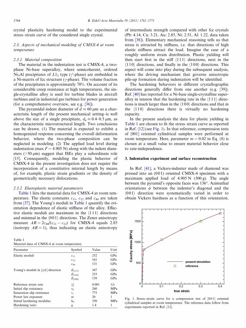
In the present analysis the data for plastic yielding inTable 1 are chosen to fit the stress–strain curve as reportedin Ref. [12] (see Fig. 1). In that reference, compression testsof [001] oriented cylindrical samples were performed atroom temperature. Here, parameter m = 0.02 in Eq. (8) ischosen at a small value to ensure material behavior closeto rate-independence.
3. Indentation experiment and surface reconstruction
In Ref. [41], a Vickers-indenter made of diamond waspressed into an (001) oriented CMSX-4 specimen with amaximum applied load of 4.905 N (500 g). The anglebetween the pyramid’s opposite faces was 136�. Azimuthalorientations / between the indenter’s diagonal and theh0 01i direction were systematically varied in order toobtain Vickers hardness as a function of this orientation.
true strain
Cauchystress[MPa
0 0.1 0.2 0.3 0.40
500
1000
present simulationreference
Fig. 1. Stress–strain curve for a compression test of [001] orientedcylindrical samples at room temperature. The reference data follow fromexperiments reported in Ref. [12].
B. Eidel / Acta Materialia 59 (2011) 1761–1771 1765
Force–displacement curves, however, were not recorded inthese indentation experiments.
The material sample of Ref. [41] is used in the presentwork to experimentally obtain 3-D data of the pile-up dis-tribution and shape of the pyramidal indents by SEM(commercial JEOL and Hitachi S520a microscopes). Thereconstruction of a digital elevation model (DEM) of theindentation craters from electron backscatter diffraction(EBSD) images (commercial version of Point Electronic)was realized by advanced algorithms in an image-process-ing software system (commercial version of Alicona).
It is worth pointing out a particular difficulty in dataacquisition for surface reconstruction and its solution inthe present work. If conventional stereographic imagesare employed, the successful surface reconstruction in adigital elevation model critically depends on sufficient opti-cal heterogeneity (points, lines, etc.) of the specimen’s sur-face. Since the third dimension is recovered by acomparison of identical material points in different stereoimages, the reconstruction fails for two types of objects:(i) if the surface does not provide enough texture on thesurface and (ii) if the surface has a recurrent structure.
Here, the indented specimen of CMSX-4 was polishedprior to indentation. As a consequence, the surface did notprovide sufficient heterogeneity as landmarks for theimage-processing software. This applied both for stereoimages from light-microscopy as well as for conventionalSEM. In the present work the problem was solved by feedingthe image-processing software with images obtained fromthe simultaneous acquisition of four single frames generatedby separate signals from a backscatter electron detector.
4. Finite-element simulations
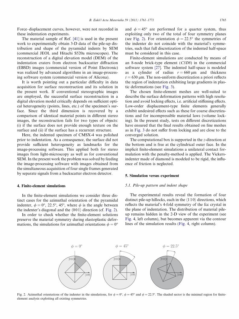
In the finite-element simulations we consider three dis-tinct cases for the azimuthal orientation of the pyramidalindenter, / = 0�, 22.5�, 45�, where / is the angle betweenthe indenter’s diagonal and the h001i direction (cf. Fig. 2).
In order to check whether the finite-element solutionspreserve the material symmetry during elastoplastic defor-mations, the simulations for azimuthal orientations / = 0�
Fig. 2. Azimuthal orientations of the indenter in the simulations, for / = 0�, /element analysis exploiting all existing symmetries.
and / = 45� are performed for a quarter system, thusexploiting only two of the total of four symmetry planes(see Fig. 2). For orientation / = 22.5� the symmetries ofthe indenter do not coincide with the material’s symme-tries, such that full discretization of the indented half-spacemust be considered in this case.
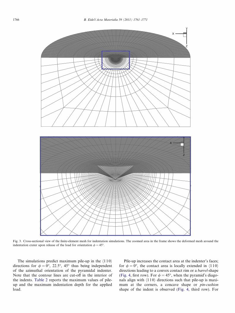
Finite-element simulations are conducted by means ofan 8-node brick-type element (C3D8) in the commercialsoftware system [27]. The indented half-space is modeledas a cylinder of radius r = 660 lm and thicknesst = 630 lm. The non-uniform discretization a priori reflectsthe region of indentation exhibiting large gradients in plas-tic deformations (see Fig. 3).
The chosen finite-element meshes are well-suited todescribe the surface deformation patterns with high resolu-tion and avoid locking effects, i.e. artificial stiffening effects.Low-order displacement-type finite elements generallyexhibit undesired effects such as these for coarse discretiza-tions and for incompressible material laws (volume lock-ing). In the present study, tests on different discretizationshave ensured that the final results obtained on fine meshesas in Fig. 3 do not suffer from locking and are close to theconverged solution.
The computational box is supported in the z-direction atthe bottom and is free at the cylindrical outer face. In theimplicit finite-element simulations a unilateral contact for-mulation with the penalty-method is applied. The Vickers-indenter made of diamond is modeled to be rigid, the influ-ence of friction is neglected.
5. Simulation versus experiment
5.1. Pile-up pattern and indent shape
The experimental results reveal the formation of fourdistinct pile-up hillocks, each in the h110i directions, whichreflects the material’s 4-fold symmetry of the fcc crystal inthe plane of indentation. The distribution of material pile-up remains hidden in the 2-D view of the experiment (seeFig. 4, left column), but becomes apparent via the contourlines of the simulation results (Fig. 4, right column).
= 45� and / = 22.5�. The shaded sector is the minimal region for finite-
X
Y
Z
X
Y
Z
Fig. 3. Cross-sectional view of the finite-element mesh for indentation simulations. The zoomed area in the frame shows the deformed mesh around theindentation crater upon release of the load for orientation / = 45�.
1766 B. Eidel / Acta Materialia 59 (2011) 1761–1771
The simulations predict maximum pile-up in the h110idirections for / = 0�, 22.5�, 45� thus being independentof the azimuthal orientation of the pyramidal indenter.Note that the contour lines are cut-off in the interior ofthe indents. Table 2 reports the maximum values of pile-up and the maximum indentation depth for the appliedload.
Pile-up increases the contact area at the indenter’s faces;for / = 0�, the contact area is locally extended in h110idirections leading to a convex contact rim or a barrel-shape(Fig. 4, first row). For / = 45�, when the pyramid’s diago-nals align with h110i directions such that pile-up is maxi-mum at the corners, a concave shape or pin-cushion
shape of the indent is observed (Fig. 4, third row). For
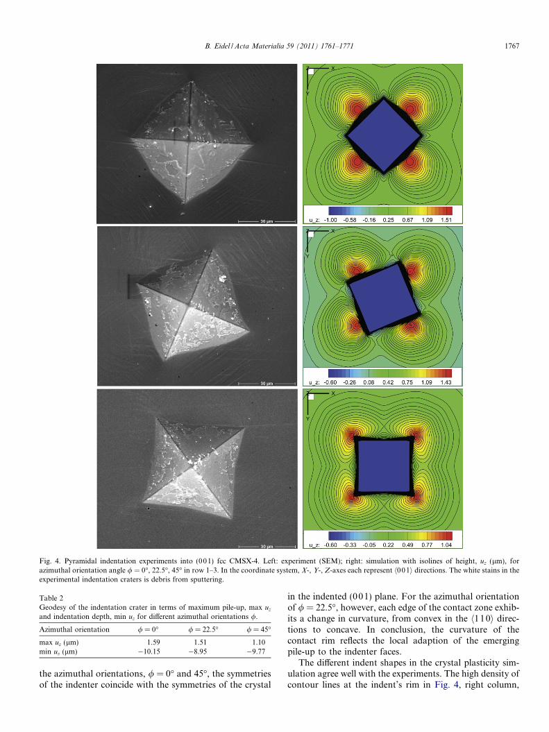
Fig. 4. Pyramidal indentation experiments into (001) fcc CMSX-4. Left: experiment (SEM); right: simulation with isolines of height, uz (lm), forazimuthal orientation angle / = 0�, 22.5�, 45� in row 1–3. In the coordinate system, X-, Y-, Z-axes each represent h001i directions. The white stains in theexperimental indentation craters is debris from sputtering.
Table 2Geodesy of the indentation crater in terms of maximum pile-up, max uz
and indentation depth, min uz for different azimuthal orientations /.
Azimuthal orientation / = 0� / = 22.5� / = 45�
max uz (lm) 1.59 1.51 1.10min uz (lm) �10.15 �8.95 �9.77
B. Eidel / Acta Materialia 59 (2011) 1761–1771 1767
the azimuthal orientations, / = 0� and 45�, the symmetriesof the indenter coincide with the symmetries of the crystal
in the indented (001) plane. For the azimuthal orientationof / = 22.5�, however, each edge of the contact zone exhib-its a change in curvature, from convex in the h110i direc-tions to concave. In conclusion, the curvature of thecontact rim reflects the local adaption of the emergingpile-up to the indenter faces.
The different indent shapes in the crystal plasticity sim-ulation agree well with the experiments. The high density ofcontour lines at the indent’s rim in Fig. 4, right column,
1768 B. Eidel / Acta Materialia 59 (2011) 1761–1771
highlights the locally extended contact zones. Summariz-ing, simulation and experiment are in qualitative agreementwith respect to the crystallographic pile-up topography,which is constantly maximum in the h110i directions,and with respect to the local adaption of pile-up to the
(a)
(b)
(d)
XY
Z
disp Uy: -15.00 -11.47 -7.94 -4.41 -0.88 2.66 6.19 9.72
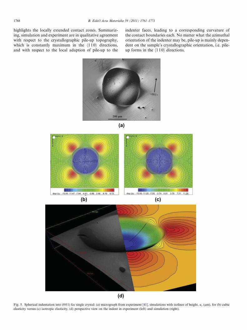
Fig. 5. Spherical indentation into (001) fcc single crystal: (a) micrograph fromelasticity versus (c) isotropic elasticity, (d) perspective view on the indent in e
indenter faces, leading to a corresponding curvature ofthe contact boundaries each. No matter what the azimuthalorientation of the indenter may be, pile-up is mainly depen-dent on the sample’s crystallographic orientation, i.e. pile-up forms in the h1 10i directions.
(c)
XY
Z
disp Uy: -15.00 -11.25 -7.50 -3.74 0.01 3.76 7.51 11.26
experiment [41], simulations with isolines of height, uy (lm), for (b) cubicxperiment (left) and simulation (right).
B. Eidel / Acta Materialia 59 (2011) 1761–1771 1769
6. Discussion: is the driving mechanism purely
crystallographic?
6.1. The role of indenter orientation
The fact that the pile-up distribution does not criticallydepend on the azimuthal orientation of the indenter sup-ports the idea that pile-up formation is determined by crys-tallographic processes rather than by the stress distributionpattern, induced under the non-isotropic pyramidalindenter.
6.2. The role of indenter shape
This conclusion is even fostered by a comparison withthe results of spherical indentation into (00 1) orientedCMSX-4 in experiment and simulation (see Fig. 5), wherethe indenter radius is R = 1.25 mm, force F = 490.25 Nand the X-, Y-, Z-axes each align with h001i directions.
The observed pile-up hillocks emerging equally in theh110i directions prove the invariance of the driving processwith respect to stress distributions induced by differentindenter geometries and orientations.
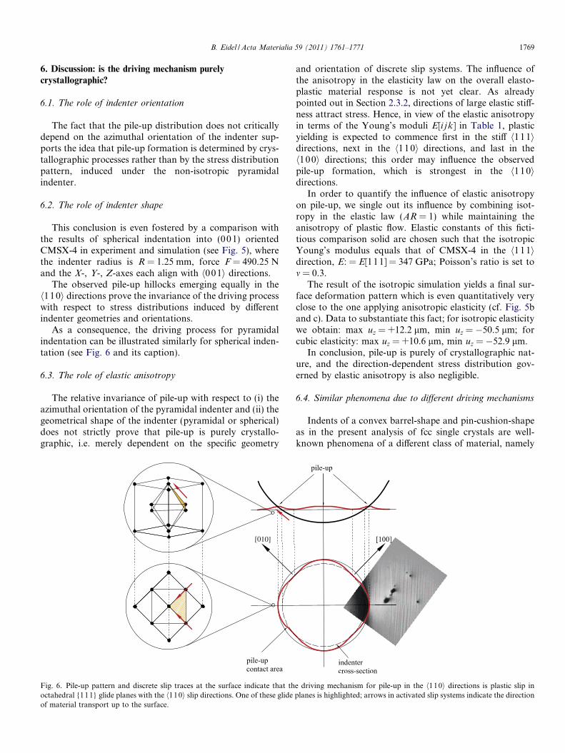
As a consequence, the driving process for pyramidalindentation can be illustrated similarly for spherical inden-tation (see Fig. 6 and its caption).
6.3. The role of elastic anisotropy
The relative invariance of pile-up with respect to (i) theazimuthal orientation of the pyramidal indenter and (ii) thegeometrical shape of the indenter (pyramidal or spherical)does not strictly prove that pile-up is purely crystallo-graphic, i.e. merely dependent on the specific geometry
[010]
Fig. 6. Pile-up pattern and discrete slip traces at the surface indicate that thoctahedral {111} glide planes with the h110i slip directions. One of these glideof material transport up to the surface.
and orientation of discrete slip systems. The influence ofthe anisotropy in the elasticity law on the overall elasto-plastic material response is not yet clear. As alreadypointed out in Section 2.3.2, directions of large elastic stiff-ness attract stress. Hence, in view of the elastic anisotropyin terms of the Young’s moduli E[i j k] in Table 1, plasticyielding is expected to commence first in the stiff h111idirections, next in the h1 10i directions, and last in theh100i directions; this order may influence the observedpile-up formation, which is strongest in the h110idirections.
In order to quantify the influence of elastic anisotropyon pile-up, we single out its influence by combining isot-ropy in the elastic law (AR = 1) while maintaining theanisotropy of plastic flow. Elastic constants of this ficti-tious comparison solid are chosen such that the isotropicYoung’s modulus equals that of CMSX-4 in the h111idirection, E: = E[111] = 347 GPa; Poisson’s ratio is set tom = 0.3.
The result of the isotropic simulation yields a final sur-face deformation pattern which is even quantitatively veryclose to the one applying anisotropic elasticity (cf. Fig. 5band c). Data to substantiate this fact; for isotropic elasticitywe obtain: max uz = +12.2 lm, min uz = �50.5 lm; forcubic elasticity: max uz = +10.6 lm, min uz = �52.9 lm.
In conclusion, pile-up is purely of crystallographic nat-ure, and the direction-dependent stress distribution gov-erned by elastic anisotropy is also negligible.
6.4. Similar phenomena due to different driving mechanisms
Indents of a convex barrel-shape and pin-cushion-shapeas in the present analysis of fcc single crystals are well-known phenomena of a different class of material, namely
e driving mechanism for pile-up in the h110i directions is plastic slip inplanes is highlighted; arrows in activated slip systems indicate the direction
contact
z
dd contact
d0d0
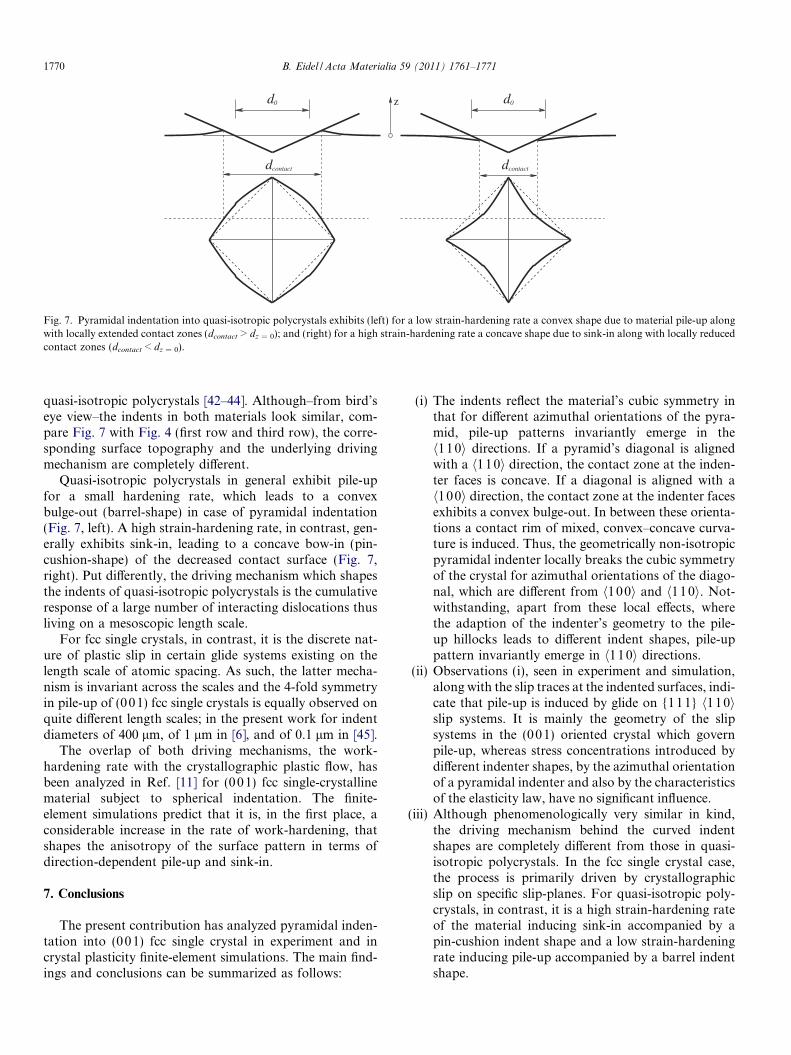
Fig. 7. Pyramidal indentation into quasi-isotropic polycrystals exhibits (left) for a low strain-hardening rate a convex shape due to material pile-up alongwith locally extended contact zones (dcontact > dz = 0); and (right) for a high strain-hardening rate a concave shape due to sink-in along with locally reducedcontact zones (dcontact < dz = 0).
1770 B. Eidel / Acta Materialia 59 (2011) 1761–1771
quasi-isotropic polycrystals [42–44]. Although–from bird’seye view–the indents in both materials look similar, com-pare Fig. 7 with Fig. 4 (first row and third row), the corre-sponding surface topography and the underlying drivingmechanism are completely different.
Quasi-isotropic polycrystals in general exhibit pile-upfor a small hardening rate, which leads to a convexbulge-out (barrel-shape) in case of pyramidal indentation(Fig. 7, left). A high strain-hardening rate, in contrast, gen-erally exhibits sink-in, leading to a concave bow-in (pin-cushion-shape) of the decreased contact surface (Fig. 7,right). Put differently, the driving mechanism which shapesthe indents of quasi-isotropic polycrystals is the cumulativeresponse of a large number of interacting dislocations thusliving on a mesoscopic length scale.
For fcc single crystals, in contrast, it is the discrete nat-ure of plastic slip in certain glide systems existing on thelength scale of atomic spacing. As such, the latter mecha-nism is invariant across the scales and the 4-fold symmetryin pile-up of (001) fcc single crystals is equally observed onquite different length scales; in the present work for indentdiameters of 400 lm, of 1 lm in [6], and of 0.1 lm in [45].
The overlap of both driving mechanisms, the work-hardening rate with the crystallographic plastic flow, hasbeen analyzed in Ref. [11] for (001) fcc single-crystallinematerial subject to spherical indentation. The finite-element simulations predict that it is, in the first place, aconsiderable increase in the rate of work-hardening, thatshapes the anisotropy of the surface pattern in terms ofdirection-dependent pile-up and sink-in.
7. Conclusions
The present contribution has analyzed pyramidal inden-tation into (001) fcc single crystal in experiment and incrystal plasticity finite-element simulations. The main find-ings and conclusions can be summarized as follows:
(i) The indents reflect the material’s cubic symmetry inthat for different azimuthal orientations of the pyra-mid, pile-up patterns invariantly emerge in theh110i directions. If a pyramid’s diagonal is alignedwith a h1 10i direction, the contact zone at the inden-ter faces is concave. If a diagonal is aligned with ah100i direction, the contact zone at the indenter facesexhibits a convex bulge-out. In between these orienta-tions a contact rim of mixed, convex–concave curva-ture is induced. Thus, the geometrically non-isotropicpyramidal indenter locally breaks the cubic symmetryof the crystal for azimuthal orientations of the diago-nal, which are different from h100i and h110i. Not-withstanding, apart from these local effects, wherethe adaption of the indenter’s geometry to the pile-up hillocks leads to different indent shapes, pile-uppattern invariantly emerge in h110i directions.
(ii) Observations (i), seen in experiment and simulation,along with the slip traces at the indented surfaces, indi-cate that pile-up is induced by glide on {111} h110islip systems. It is mainly the geometry of the slipsystems in the (001) oriented crystal which governpile-up, whereas stress concentrations introduced bydifferent indenter shapes, by the azimuthal orientationof a pyramidal indenter and also by the characteristicsof the elasticity law, have no significant influence.
(iii) Although phenomenologically very similar in kind,the driving mechanism behind the curved indentshapes are completely different from those in quasi-isotropic polycrystals. In the fcc single crystal case,the process is primarily driven by crystallographicslip on specific slip-planes. For quasi-isotropic poly-crystals, in contrast, it is a high strain-hardening rateof the material inducing sink-in accompanied by apin-cushion indent shape and a low strain-hardeningrate inducing pile-up accompanied by a barrel indentshape.
B. Eidel / Acta Materialia 59 (2011) 1761–1771 1771
(iv) The crystal plasticity model accounting for glide inoctahedral {11 1} h110i slip systems for fcc crystal-line material predicts in finite-element simulationsthe pile-up pattern formation and the material’s localaccomodation to the indenter.
Acknowledgements
The author is grateful to Klaus Wintrich for providingthe CMSX-4 specimen for the present measurements usingSEM and EBSD and to Marco Schurg for assistance inpreparing optimized FE meshes. The author acknowledgesfinancial support through ThyssenKrupp AG, Bayer Mate-rialScience AG, Salzgitter Mannesmann ForschungGmbH, Robert Bosch GmbH, Benteler Stahl/RohrGmbH, Bayer Technology Services GmbH and the stateof North-Rhine Westphalia as well as the European Com-mission in the framework of the European Regional Devel-opment Fund (ERDF).
References
[1] Dyer LD. Trans ASM 1965;58:620.[2] Chang SC, Chen HC. Acta Metall Mater 1995;43:2501.[3] Stelmashenko NA, Brown LM. Philos Mag A 1996;74:1195.[4] Nibur KA, Bahr DF. Scripta Mater 2003;49:1055.[5] Hollatz M, Bobeth M, Pompe W, Marx V. Acta Mater 1996;44:4149.[6] Wang Y, Raabe D, Kluber D, Roters F. Acta Mater 2004;52:229.[7] Zaafarani N, Raabe D, Singh RN, Roters F, Zaefferer S. Acta Mater
2006;54:1863.[8] Zaafarani N, Raabe D, Roters F, Zaefferer S. Acta Mater 2008;56:31.[9] Liu Y, Wang B, Yoshino M, Roy S, Lu H, Komanduri R. J Mech
Phys Solids 2005;53:2718.[10] Liu Y, Varghese S, Ma J, Yoshino M, Lu H, Komanduri R. Int J
Plast 2008;24:1990.[11] Eidel B, Gruttmann F. Comput Mater Sci 2007;39:172.[12] Zambaldi C, Roters F, Raabe D, Glatzel U. Mater Sci Eng A
2007;454–455:433.[13] Casals O, Forest S. Comput Mater Sci 2009;45:774.[14] Zambaldi C, Raabe D. Acta Mater 2010;58:3516.
[15] Stelmashenko NA, Walls MG, Brown LM, Milman YV. Acta MetallMater 1993;41:2855.
[16] Kovacs Zs, Chinh NQ, Lendvai J. J Mater Res 2001;16:1171.[17] Peralta P, Ledoux R, Dickerson R, Hakik M, Dickerson P. Metall
Mater Trans A 2004;35:2247.[18] Casals O, Ocenasek J, Alcala J. Acta Mater 2007;55:68.[19] Alcala J, Casals O, Ocenasek J. J Mech Phys Solids 2008;56:3277.[20] Taylor GI. J Inst Metals 1938;62:307.[21] Hill R. J Mech Phys Solids 1965;13:89.[22] Theodosiu C. In: Simmons JA, editor, Proceedings of the conference
on fundamental aspects of dislocation theory, US National Bureau ofStandards; 1970. p. 837.
[23] Rice J. J Mech Phys Solids 1971;19:433.[24] Hill R, Rice J. J Mech Phys Solids 1972;20:401.[25] Asaro RJ. J Appl Mech 1983;50:921.[26] Asaro RJ, Needleman A. Acta Metall 1985;33:923.[27] ABAQUS/Standard, 2009. Theory and user’s manual, Version 6.9,
ABAQUS Inc.[28] Huang Y. Mech. report 178, Cambridge (MA): Division of Applied
Sciences, Harvard University; 1991.[29] Kysar JW. Addendum to ’A user-material subroutine incorporating
single crystal plasticity in the ABAQUS finite element program’.Mech. report 178, Cambridge (MA): Division of Applied Sciences,Harvard University; 1997.
[30] Asaro RJ, Rice JR. J Mech Phys Solids 1977;25:309.[31] Kroner E. Arch Ration Mech Anal 1960;4:273.[32] Lee EH. J Appl Mech 1969;36:1.[33] van der Giessen E, Besseling JF. Mathematical modelling of inelastic
deformation. London: Chapman & Hall; 1994.[34] Hutchinson JW. Proc Roy Soc A 1970;319:247.[35] Pierce D, Asaro RJ, Needleman A. Acta Metall 1983;31:1951.[36] Reed RC. The superalloys: fundamentals and applications. Cam-
bridge: Cambridge University Press; 2006.[37] Sieborger D, Knake H, Glatzel U. Mater Sci Eng A 2001;298:26.[38] Simmonds D, Wang H. Single crystal elastic constants and calculated
aggregate properties: a handbook. 2nd ed. Cambridge (MA): MITPress; 1970.
[39] Kocks UF, Mecking H. Prog Mater Sci 2003;48:171.[40] Westbrooke EF, Forero LE, Ebrahimi F. Acta Mater 2005;52:2137.[41] Wintrich K. Schadigungsverhalten der einkristallinen Superlegierung
CMSX-4 bei Hochtemperaturbelastung. Ph.D. Dissertation, TUDarmstadt; 2004. (in German)
[42] Bolshakov A, Pharr GM. J Mater Res 1998;13:1049.[43] Giannakopoulos AE, Suresh S. Scripta Mater 1999;40:1191.[44] Alcala J, Barone AC, Anglada M. Acta Mater 2000;48:3451.[45] Kiely JD, Houston JE. Phys Rev B 1998;77(7):12588.