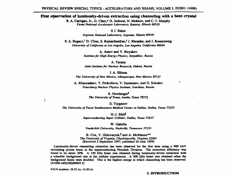
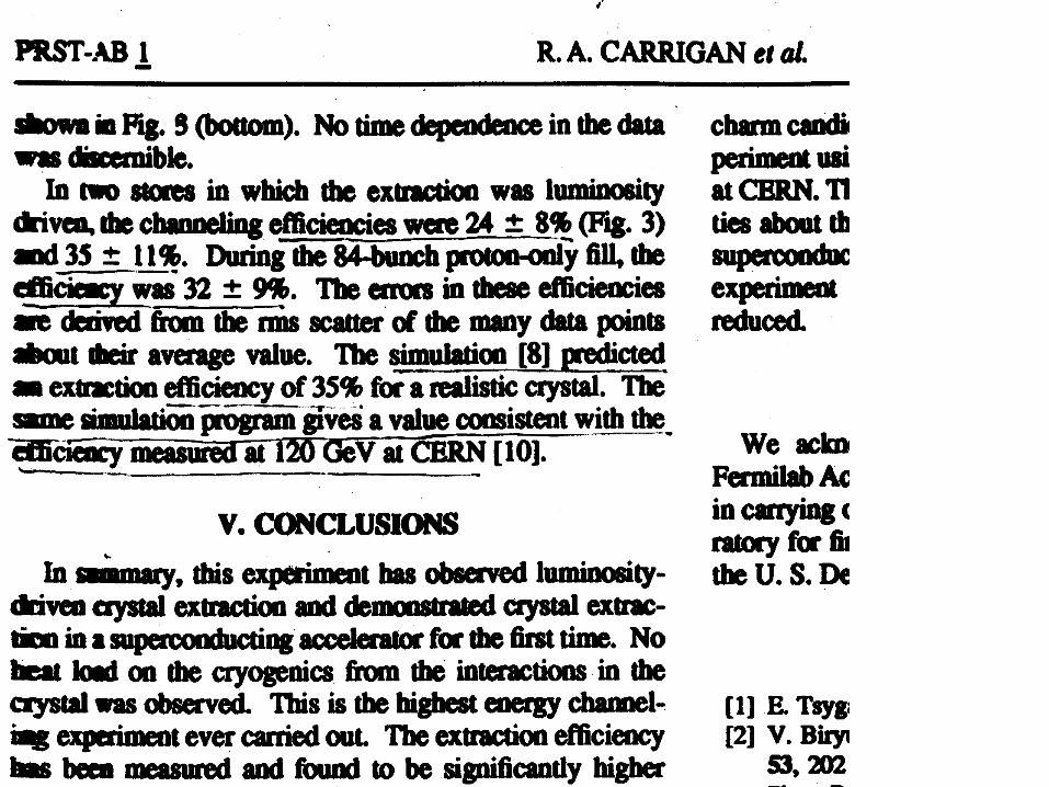
Cleaning performance of LHC collimation system during the energy ramp
Upload
velma-combsCategory
view
49download
1description
Crystal collimation for LHC
Valery BiryukovIHEP Protvino
Vincenzo GuidiFerrara University and INFN
Walter ScandaleCERN
CERN, Geneva, 24 April 2003
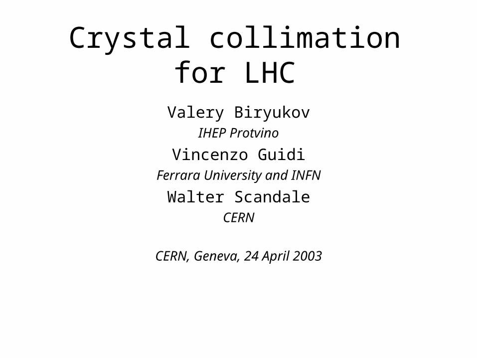
Borrowed from Ray Fliller’s talk at Paris EPAC 2002
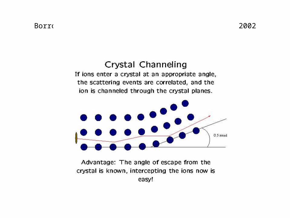
Crystal Channeling
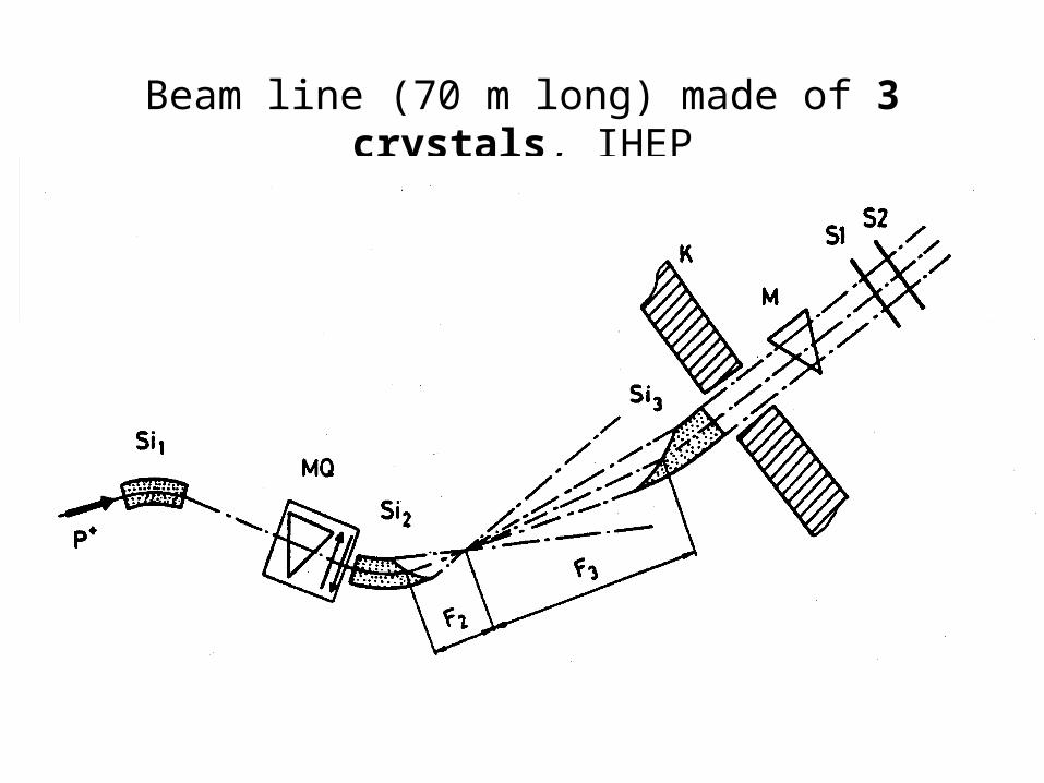
Beam line (70 m long) made of 3 crystals, IHEP
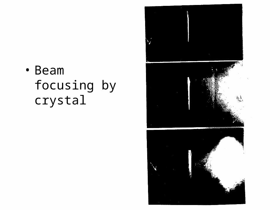
• Beam focusing by crystal
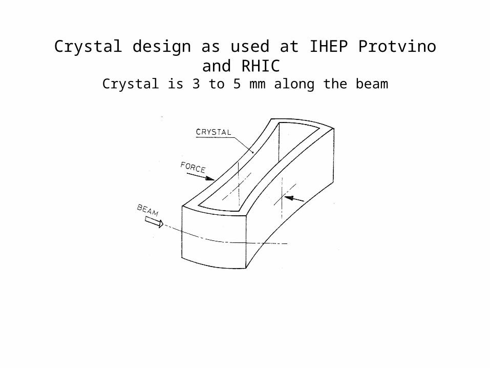
Crystal design as used at IHEP Protvino and RHIC Crystal is 3 to 5 mm along the beam
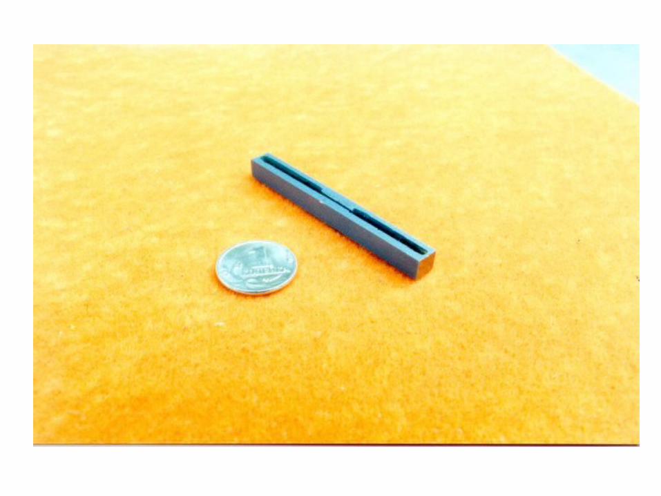
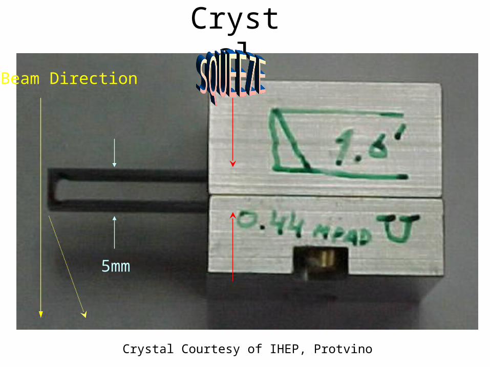
Crystal
5mm
Beam Direction
Crystal Courtesy of IHEP, Protvino
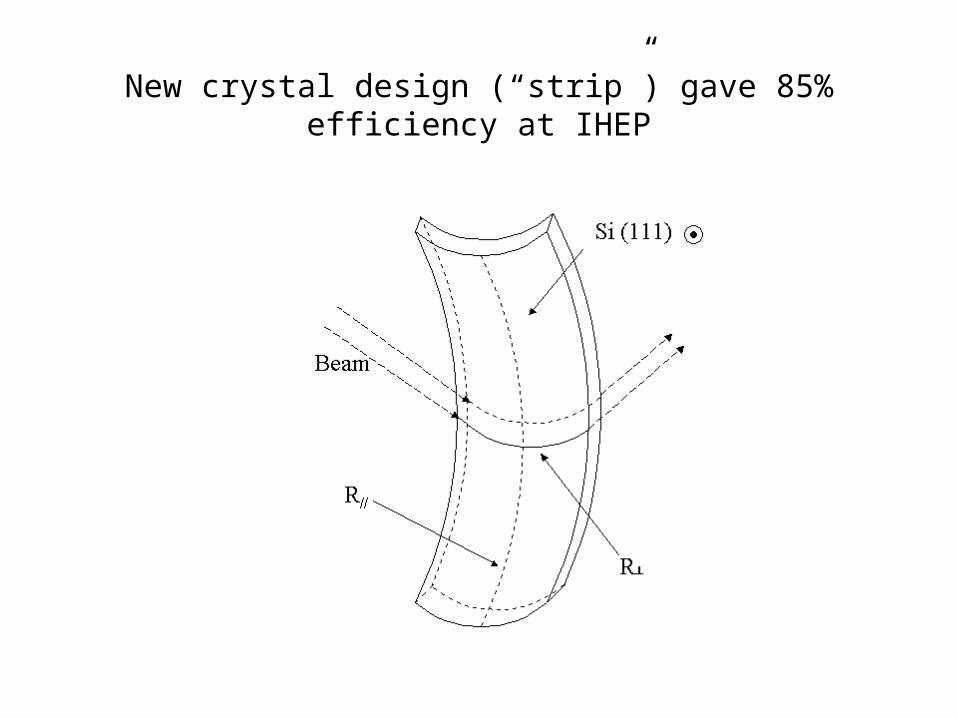
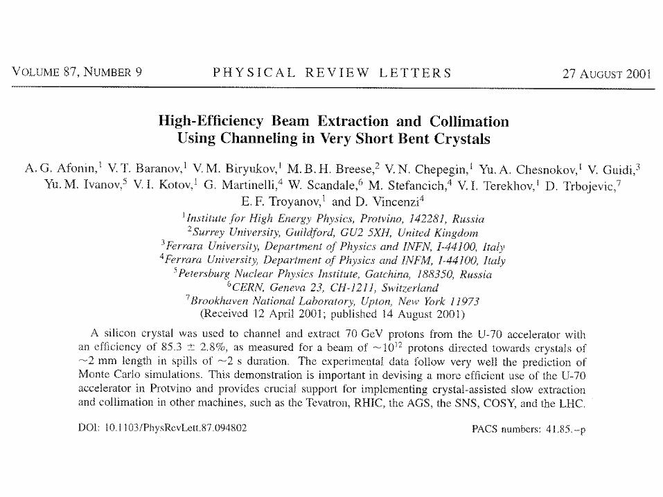
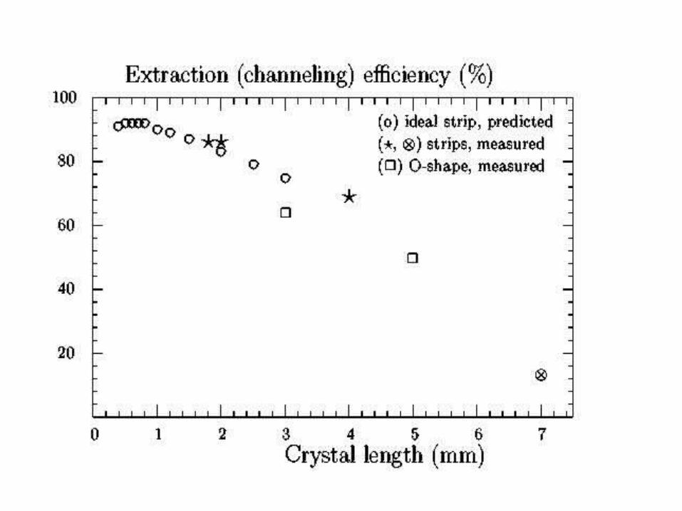
New crystal design (“strip”) gave 85% efficiency at IHEP
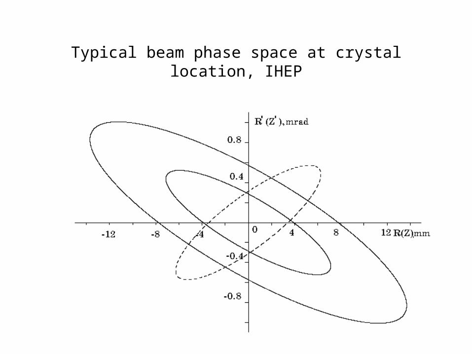
Typical beam phase space at crystal location, IHEP
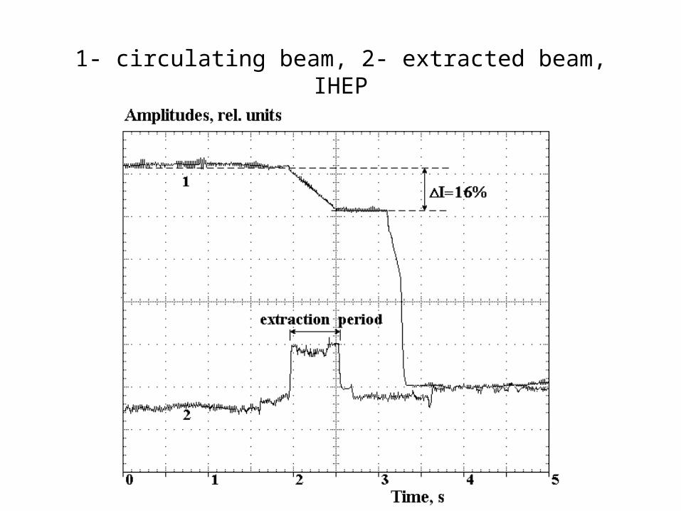
1- circulating beam, 2- extracted beam, IHEP
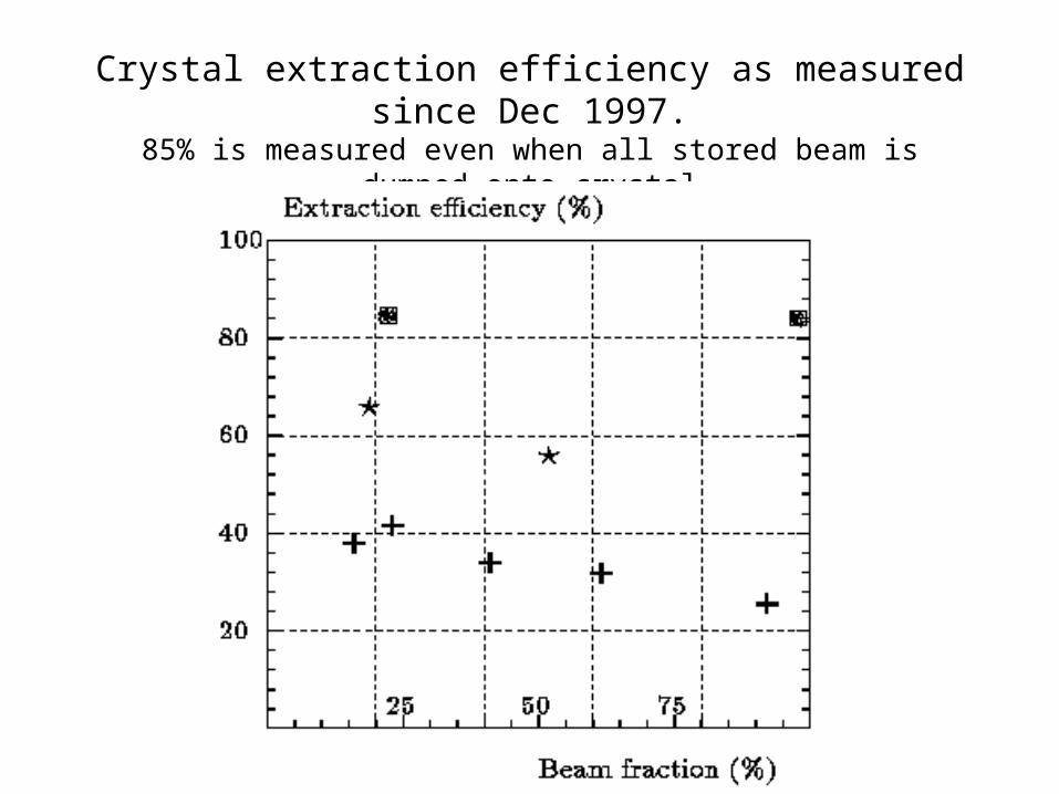
Crystal extraction efficiency as measured since Dec 1997.85% is measured even when all stored beam is dumped onto crystal
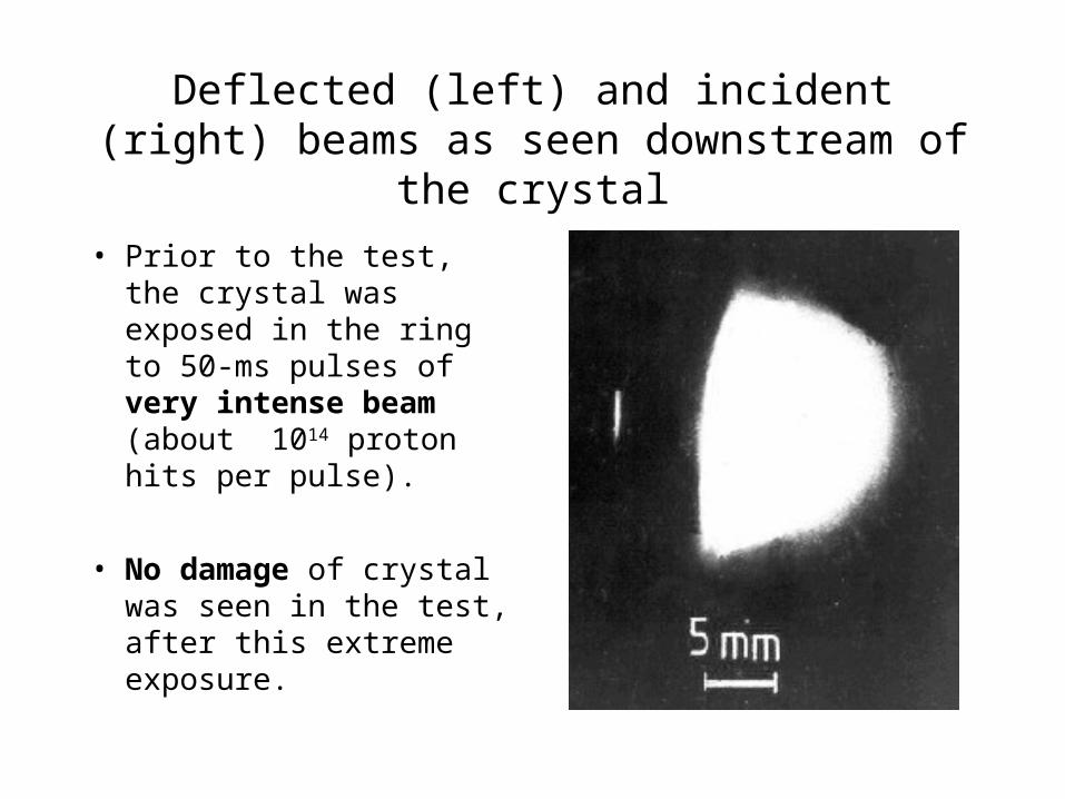
Deflected (left) and incident (right) beams as seen downstream of the crystal
• Prior to the test, the crystal was exposed in the ring to 50-ms pulses of very intense beam (about 1014 proton hits per pulse).
• No damage of crystal was seen in the test, after this extreme exposure.
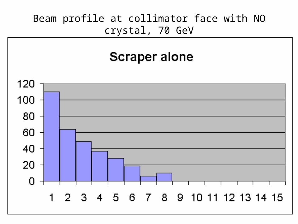
Beam profile at collimator face with NO crystal, 70 GeV
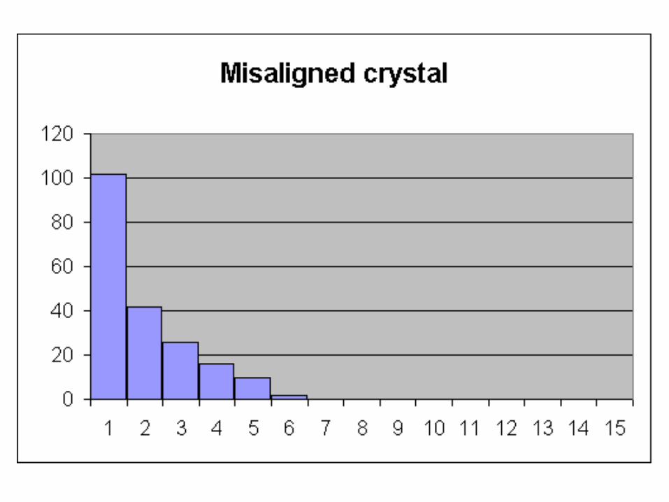
Misaligned x
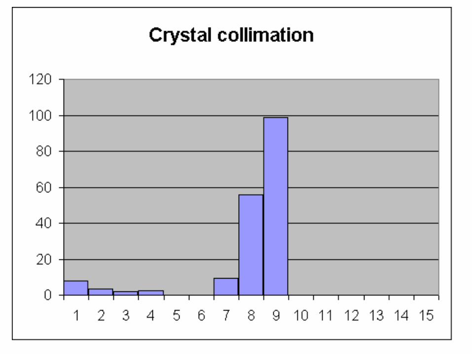
Crystal collimation
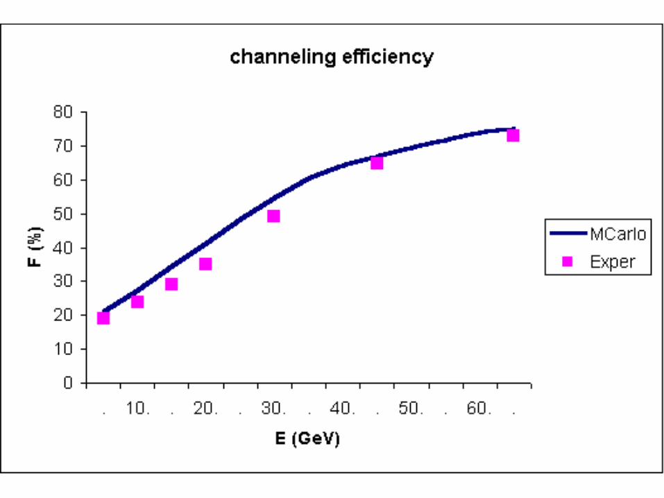
Effy vs Energy
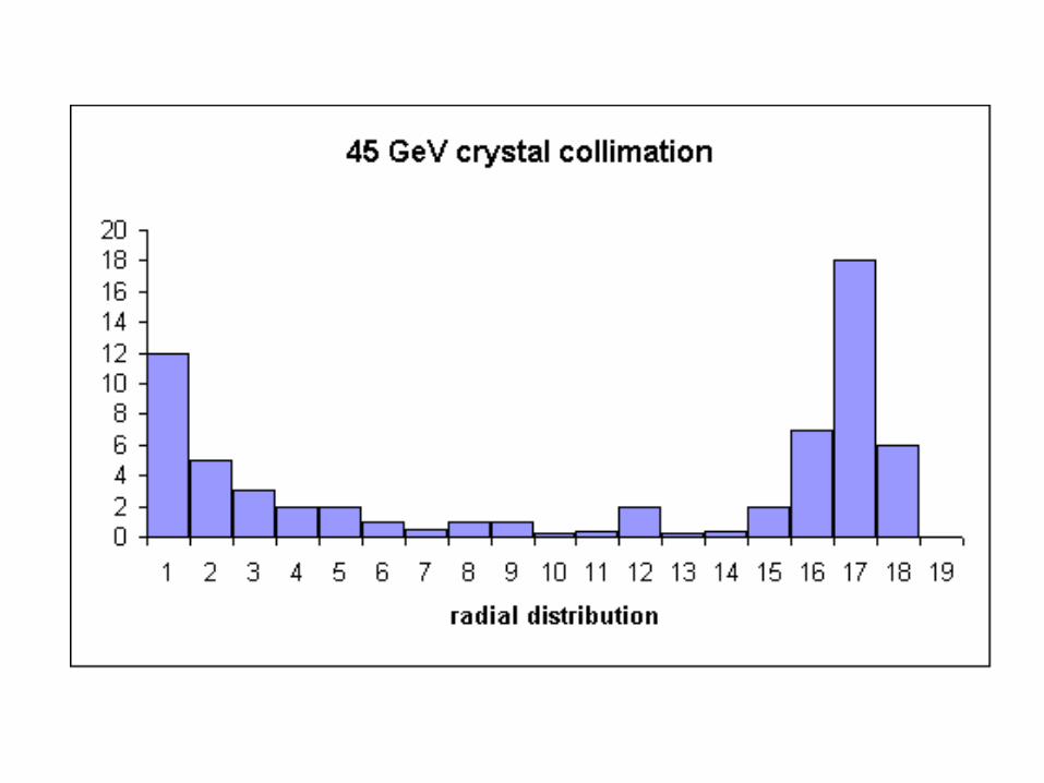
45 GeV
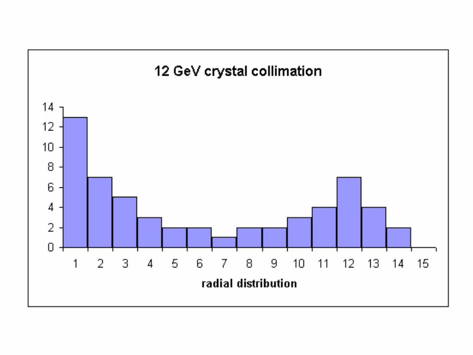
12 GeV
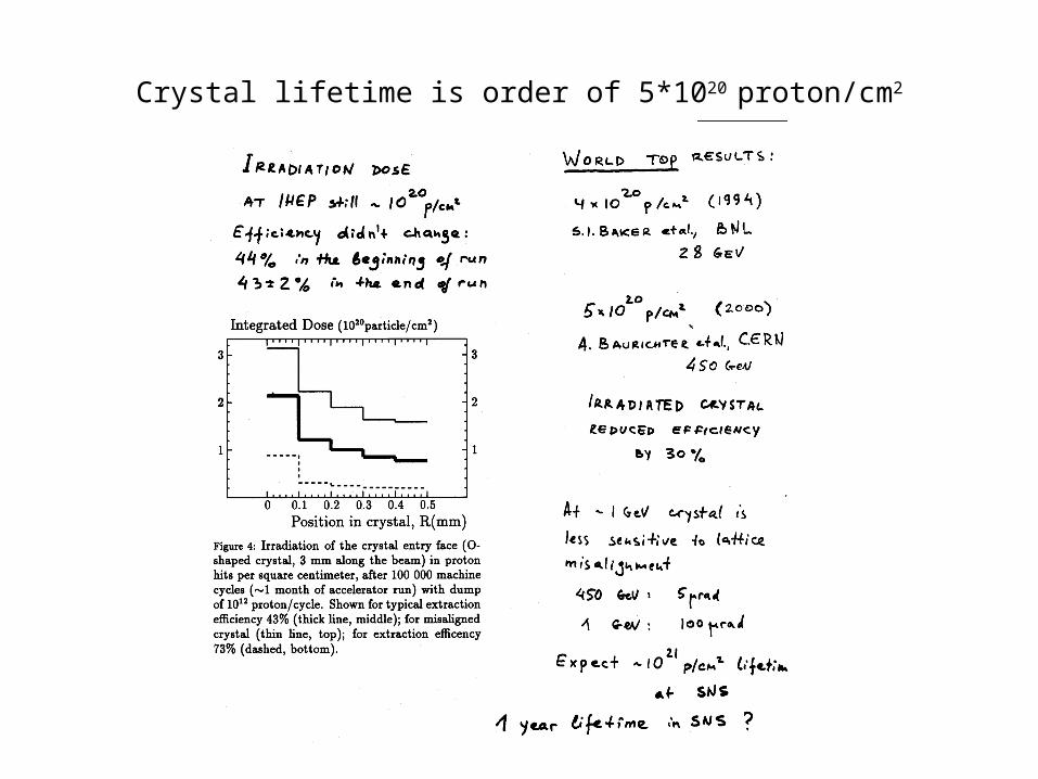
Crystal lifetime is order of 5*1020 proton/cm2
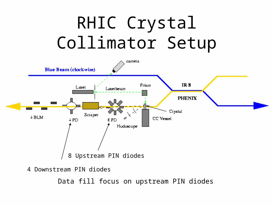
RHIC Crystal Collimator Setup
8 Upstream PIN diodes
4 Downstream PIN diodes
Data fill focus on upstream PIN diodes
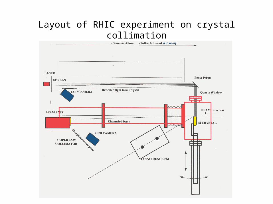
Layout of RHIC experiment on crystal collimation
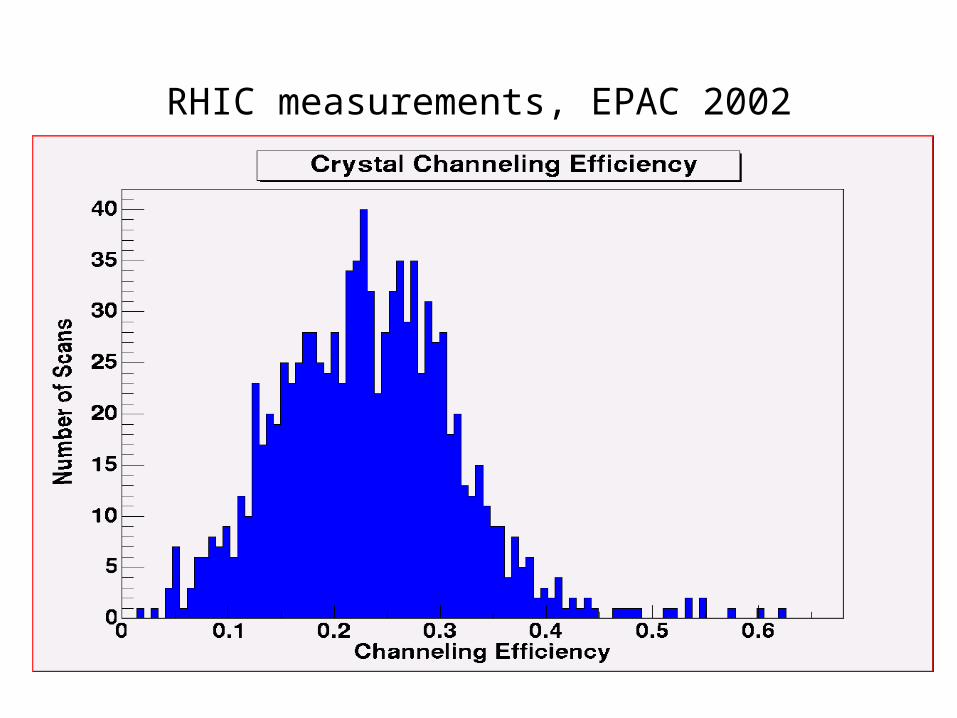
RHIC measurements, EPAC 2002
Simulations of LHC crystal collimation
Simulations with smaller bending, 0.1 mrad
Two bending options compared: 0.2 and 0.1 mrad
Efficiency vs bending angle
Background suppression factor vs crystal bending
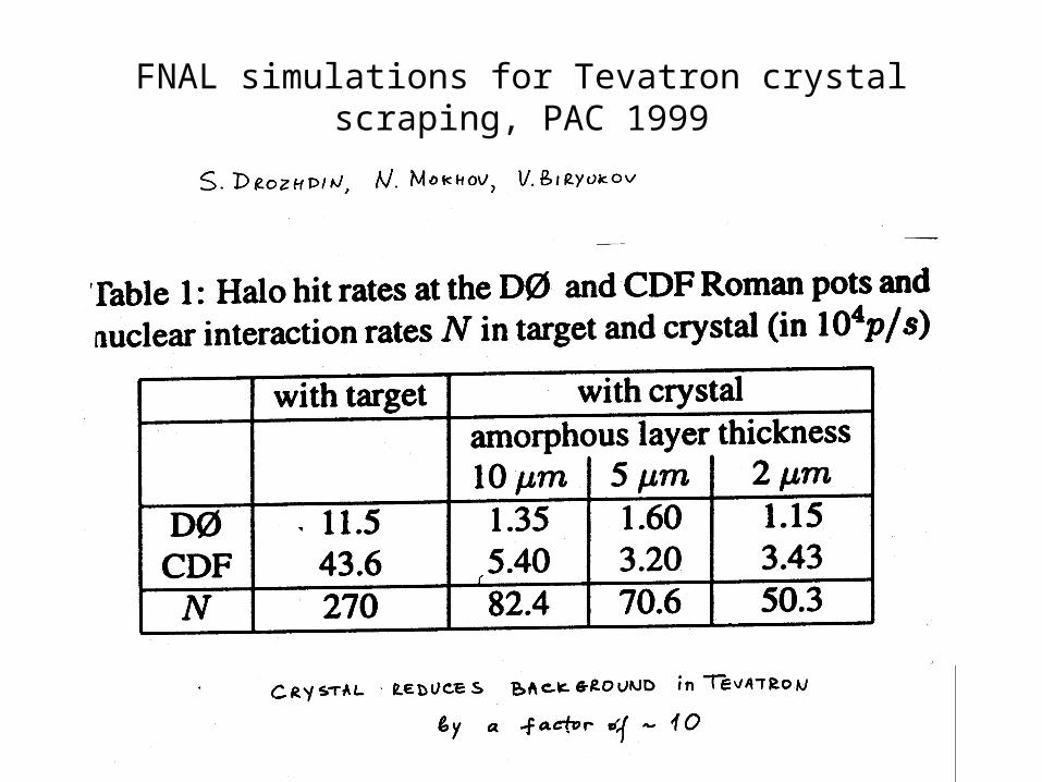
FNAL simulations for Tevatron crystal scraping, PAC 1999
Conclusion
• Simulations and experiments promise
10-fold improvement in backgrounds
at TeV accelerators if bent crystal is used as primary scraper.
• No problems with high intensity or lifetime.
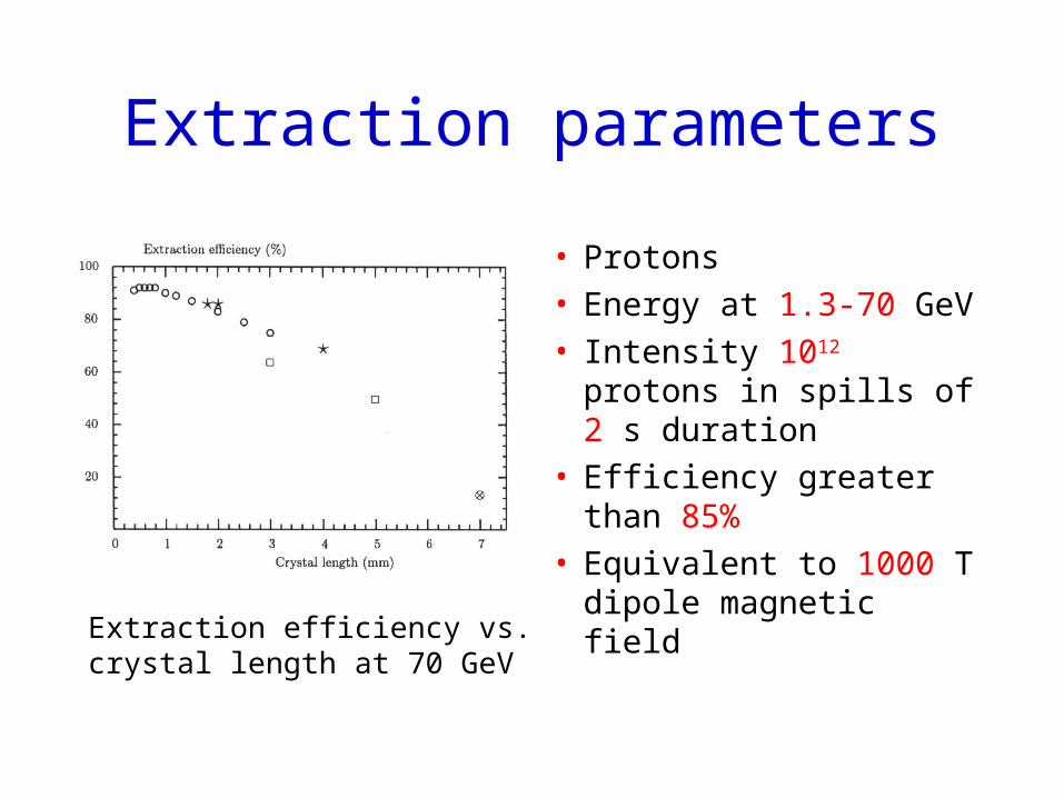
Extraction parameters
• Protons • Energy at 1.3-70 GeV• Intensity 1012 protons
in spills of 2 s duration• Efficiency greater than
85%• Equivalent to 1000 T
dipole magnetic fieldExtraction efficiency vs. crystal length at 70 GeV
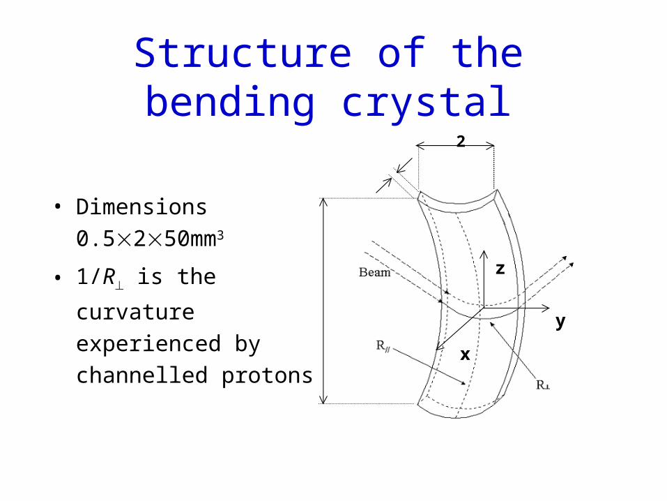
Structure of the bending crystal
y
x
z50
0.52
• Dimensions
0.5250mm3
• 1/R is the curvature
experienced by channelled
protons
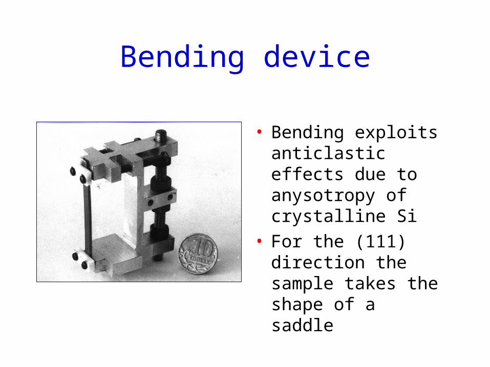
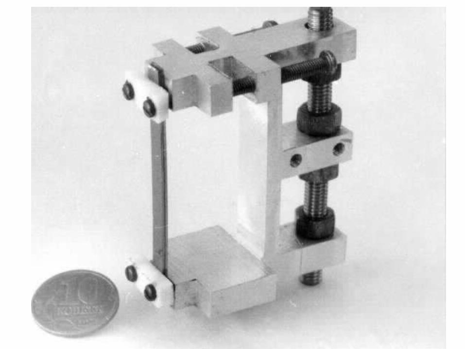
Bending device
• Bending exploits anticlastic effects due to anysotropy of crystalline Si
• For the (111) direction the sample takes the shape of a saddle
Preparation of the Si samples I
• Starting material is prime-grade, (111) oriented 525-m-thick silicon wafer
• In previous runs there came out that a surface layer as thick as 30 m was rich in scratches, dislocations, line defects and anomalies that would reduce channelling efficiency
• Such a layer originated in the mechanical cutting for manufacturing the samples
• Thus we attempted removal of the layer
Preparation of the Si samples II
• Preliminary cleaning to organic and metallic impurities from the surface of the wafers by H2O2, NH4OH, HF, HCl,...
• Coverage of the largest surfaces by Apiezon wax• Cutting of the samples by a diamond-blade saw
avoiding alignment with major crystalline axes.
• Planar etching (HF, HNO3 and CH3COOH, 2:15:5) with a timing set for 30 m thinning.
More info in Rev. Sci. Instrum. 73 (2002) 3170-3173
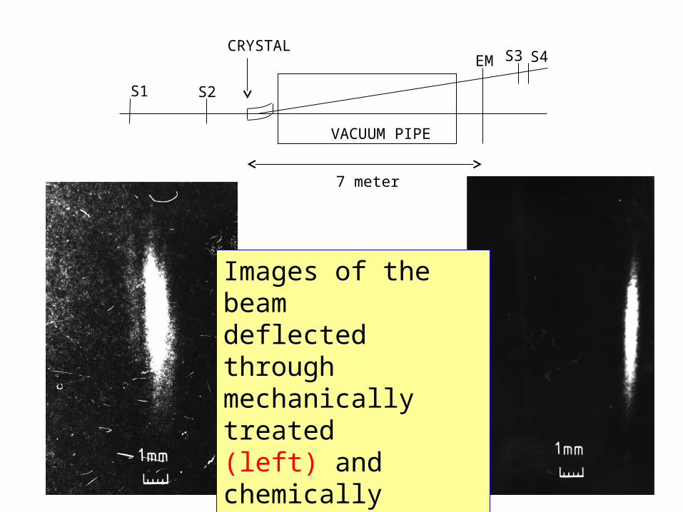
7 meter
VACUUM PIPE
CRYSTAL
S1
S4S3
S2
EM
Images of the beam deflected through mechanically treated (left) and chemically polished crystals (right)