CRYOSTAT COVER MECHANISM FOR THE HERSCHEL...
9
CRYOSTAT COVER MECHANISM FOR THE HERSCHEL SATELLITE: DESIGN AND QUALIFICATION TEST RESULTS Paul Janu, Manfred Falkner, Ludwig Supper, Rudolf Schermann, Christian Laa, Gerhard Traxler Austrian Aerospace GmbH (AAE), Stachegasse 16, A-1120 Vienna, Austria Tel.: +43 1 80199 2740, Fax.: +43 1 80199 6950, Email:[email protected] ABSTRACT The Cryostat Cover Mechanism closes the Cryostat Vacuum Vessel on ground and is preventing air- leakage from outside and keeping high-vacuum inside the Cryostat of the European infrared space telescope HERSCHEL. The cover and its mechanisms are single point failure critical items for the entire mission and are designed for cryogenic operation. Austrian Aerospace was contracted by EADS ASTRIUM and prime contractor ALCATEL to develop the Cryostat Cover Mechanism, which consists of the cover itself which features an active cooling loop, a deployment mechanism and a non-explosive hold-down- and release mechanism (see Figure 1). The main challenges are clearly the actuation temperature at 70 K, the required tightness on ground, and the high reliability of this device. The QM has been successfully delivered in January 2005, the FM will be finally delivered by end of 2005. The scope of this presentation is to present briefly the design of the Cryocover, and to highlight the qualification test results. 1. MAIN DESIGN FEATURES Tightness of the Cryostat Cover to the Vacuum Vessel upper bulkhead plate is performed via an o-ring sealing, which is equally pre-loaded over its circumference. The needed force is applied via a pre- loaded lever. This lever is fixed on one end by 2 hinges and on the other end by the hold down & release mechanism. The lever is driven by torsion springs. To avoid sticking of the sealing to the Cryostat Vacuum Vessel after long closure time, 4 kick springs are equally distributed on the Cryostat Cover circumference. The hold down and release mechanism is spring actuated and uses a cryogenic non-explosive separation nut. Figure 1-Cryostat Cover overview 1.1 Special O-ring Sealing The o-ring sealing is made from the fluorcarbon elastomer material Viton with a diameter of about 300mm. It is mounted to the Cryostat Cover via a high precision dove tail groove and tightens to the CVV upper bulkhead plate via a high precision flat surface I/F. Before integration of the sealing a special vacuum bake out is performed. This is needed to remove short carbon-hydrogen chains from the Viton material, which would lead to sticking of the sealing to the metallic surface. Directly besides the dove tail sealing groove a smaller second dove tail groove is used for fixation and support of support poles made of Vespel SP1. They get in contact with the CVV upper bulkhead plate after reaching a deformation of the Viton sealing of 20 %, thus preventing too high deformation of the sealing and metal to metal contact of the cover to the CVV upper bulkhead plate. 1.2 Cover The cover is a light weight aluminum structure. It is equipped with the grooves for sealing and Vespel poles fixation in the lower area and an Ball Bearing I/F in the upper area. Preloaded lever Vacuum Vessel upper bulkhead plate Hold down and release mechanism 2x hinge, 4x torsion springs 2x end stops 4x kick spring
Transcript of CRYOSTAT COVER MECHANISM FOR THE HERSCHEL...

CRYOSTAT COVER MECHANISM FOR THE HERSCHEL SATELLITE: DESIGN ANDQUALIFICATION TEST RESULTS
Paul Janu, Manfred Falkner, Ludwig Supper, Rudolf Schermann, Christian Laa, Gerhard TraxlerAustrian Aerospace GmbH (AAE), Stachegasse 16, A-1120 Vienna, Austria
Tel.: +43 1 80199 2740, Fax.: +43 1 80199 6950, Email:[email protected]
ABSTRACT
The Cryostat Cover Mechanism closes the CryostatVacuum Vessel on ground and is preventing air-leakage from outside and keeping high-vacuum insidethe Cryostat of the European infrared space telescopeHERSCHEL. The cover and its mechanisms are singlepoint failure critical items for the entire mission andare designed for cryogenic operation.
Austrian Aerospace was contracted by EADSASTRIUM and prime contractor ALCATEL todevelop the Cryostat Cover Mechanism, which consistsof the cover itself which features an active coolingloop, a deployment mechanism and a non-explosivehold-down- and release mechanism (see Figure 1). Themain challenges are clearly the actuation temperature at70 K, the required tightness on ground, and the highreliability of this device.
The QM has been successfully delivered in January2005, the FM will be finally delivered by end of 2005.
The scope of this presentation is to present briefly thedesign of the Cryocover, and to highlight thequalification test results.
1. MAIN DESIGN FEATURES
Tightness of the Cryostat Cover to the Vacuum Vesselupper bulkhead plate is performed via an o-ringsealing, which is equally pre-loaded over itscircumference. The needed force is applied via a pre-loaded lever. This lever is fixed on one end by 2 hingesand on the other end by the hold down & releasemechanism. The lever is driven by torsion springs. Toavoid sticking of the sealing to the Cryostat VacuumVessel after long closure time, 4 kick springs areequally distributed on the Cryostat Covercircumference. The hold down and release mechanismis spring actuated and uses a cryogenic non-explosiveseparation nut.
Figure 1-Cryostat Cover overview
1.1 Special O-ring SealingThe o-ring sealing is made from the fluoelastomer material Viton with a diameter o300mm. It is mounted to the Cryostat Cover viprecision dove tail groove and tightens to thupper bulkhead plate via a high precision flatI/F.Before integration of the sealing a special vacuuout is performed. This is needed to removcarbon-hydrogen chains from the Viton mwhich would lead to sticking of the sealingmetallic surface.Directly besides the dove tail sealing groove asecond dove tail groove is used for fixation andof support poles made of Vespel SP1. Theycontact with the CVV upper bulkhead plareaching a deformation of the Viton sealing othus preventing too high deformation of the seametal to metal contact of the cover to the CVbulkhead plate.
1.2 CoverThe cover is a light weight aluminum structuequipped with the grooves for sealing and Vespfixation in the lower area and an Ball Bearing Iupper area.
Preload
Hold down andrelease mechanism
2x hinge, 4x torsion 2x end stops
Vacuum Vesselupper bulkheadplate
rcarbonf abouta a highe CVV surface
m bakee shortaterial,
to the
smaller support get inte afterf 20 %,ling andV upper
re. It isel poles
/F in the
ed lever
springs
4x kick spring

Lever
Pre loadadjustment device
MLI
Mechanical stop forlimitation of therotation angle
Figure 2 – I/F of the cover to the lever
It provides the mechanical I/F to the fixation devices ofthe thermally isolated cover heat shield.The cover has a conical shape with wall thickness 3mm. The light weight design was possible onlybecause the bending moments of the lower sealing areawere eliminated as far as possible for all load cases byoptimization of the location of the groove and flangedesign.The cover has also the I/F to the Johnston Couplingsand an electrical connector. Tightening of these units isperformed also via Viton o-ring seals.
1.3 Cover Heat Shield with Cooling Loop andJohnston Couplings
In order to limit parasitic heat load through the closedcover during ground operation the cover is equippedwith a special heat shield in its lower area. It providesan effective emissivity of 0.01 at ambient temperature.This low value is reached by integration of 2 MLIpackages between the cover upper structure and theheat shield.
Figure 3- Cover heat shield MLI andCouplings
The cover heat shield is equipped winitrogen/helium cooling loop in order temperature range from 25 K to 90 K. Foof the nitrogen/helium supply the coverwith special light weight Johnston Coupstay mounted at flight. Disconnectnitrogen/helium supply lines is planneddays before flight.
Figure 4 – Cooling loop and Johnston
The lower surface of the cover heat shieldto 2 special mirror shapes for calibration and SPIRE instruments. The mirrors haveprecision and have an infrared emissivity of 0.04 at 80 K within a small toleranspecial test program was performed to fcorrect machining parameters for gettingsurface condition.
Cover Location ofball joint
Cover heatshield internalside
JohnstonCoupling I/F tothe cover
Johnston
th an activeto achieve ar connection is equippedlings, which
ion of the only a few
Couplings
is machinedof the PACS to be of high requirementce range. A
igure out the the required
2x thermalsensors

Figure 5-Cover heat shield mirrors
The cover heat shield as well as the cooling loop ismanufactured from aluminum alloy with high thermalconductivity also at cryogenic temperatures in order toprovide equal temperature distribution over the mirrorsurfaces. The Johnston Couplings are manufacturedfrom stainless steel because they have to provide highthermal isolation capability. The I/F between the steelJohnston Couplings and the aluminium cooling loop isa welded connection with a special transition inbetween. An extended test program was performed onthis welding process.
1.4 Preloaded LeverThe lever has the function of providing equal loaddistribution over the circumference of the cover sealingarea. Therefore it is equipped with a ball joint as I/F tothe cover (see Figure 2).The lever allows a pre load force of 10 kN.
1.5 Hinges / Torsion SpringsThe hinges support the cover via the lever in closedconfiguration and provide a highly reliable (3xredundancy and avoiding metal to metal contact) andlow friction bearing at the opening campaign. Hingehousing material is aluminum, shaft material isstainless steel.For obtaining the opening torque 4 (redundant) torsionsprings are used. Fixation of the springs is performedin a way to avoid load introduction into the bearings.This design provides a nearly frictionless springsupport (see Figure 11).
1.6 Hold Down and Release Mechanism (HRM)The HRM is designed as a three lever system to becompliant to the required kinematics. The motion ofthe connection lever in the area of the non explosiveseparation nut has to be a linear translation parallel tothe release bolt axis, in order to avoid jamming of thebolt upon release.
Non explosiveseparation nut
Connectionlever
HRM kneelever withrelease I/F
Figure 6 – Hold down and release mecha
The knee lever is equipped with a Pglassfibre liner on the I/F to the lever towelding.
1.7 Non-Explosive Separation NutSupplier for the Non-Explosive separationcompany G&H.Some modifications had to be performcommercial item, to provide fully complcryogenic temperatures. As a result ocomponent level tests most non-metallic mremoved, because they broke at thetemperature release and produced debris. Tthe threaded segments was changed slighsingular load peaks at the release campaign
1.8 Kick SpringsAt the opening campaign during the firscover is mainly driven by the kick springs.springs used, made from titanium alloy sheload per kick spring at 70 K is 462 N.The kick springs overcome potential sticsealing on the metal surface of the bulkhead plate.Component level tests have shown that tsticking is only given, when the sealing isbaked out. If vacuum bake out was pesticking effect could be realized also afterinternal evacuation of 40 days. At the comtests it was realized, that a sticking formeasured only, if the opening campaigquick. The lower the opening speed, the lo
Lever2x torque sactuators
2xlinearspringactuator
nism
TFE woven avoid cold
nut was the
ed on theiance to thef the first
aterials were cryogeniche shape oftly to avoid.
t lift off the There are 4ets. The pre
king of theCVV upper
he ability of not vacuumrformed no closure andponent levelce could ben was verywer was the
pring

force and the force went to zero at an opening speed of1 minute. This effect could not be realized at thefunctional opening test because of the high force of the4 kick springs.
2. RESULTS OF THE COMPONENTLEVEL AND QUALIFICATION LEVEL TESTCAMPAIGN
2.1 Special O-ring Sealing
2.1.1 Component Level test over temperaturerange 70 K to 303 K
Figure 7-Cryostat for component level tests
1 E 06
1.E-05
1.E-04
1.E-03
1.E-02
1.E-01
Leak
rate
in m
bar.l
/sec
200.00210.00
220.00
230.00
240.00250.00
260.00
270.00
280.00290.00
300.00
310.00
29.04 14:00 29.04 15:00 29.04 16:00 29.04 17:00 29.04 18:00
Tem
pera
ture
in K
Ch10 - Diode 2 Ch7 - Pt100 Ch8 - Pt100
Figure 8 - Sealing leakage over temperature
The sealing is not tight at cryogenic temperatures.Reason for that is, that the Fluor carbon material getsglass hard at cryogenic temperatures.For the test the arrangement was cooled down tocryogenic temperature and slowly heated up. At about253 K (-20°C) the sealing gets back its elastomerestructure and starts to tighten then.
The test shows, that the sealing was not degraded at thecryogenic temperature and gets back full tightnesscapability after warming up to room temperature. Socooling down and dynamic opening at cryogenictemperature do not degrade the sealing. The samesealing was used for the complete qualification testprogram. The helium leakage values did not changefrom beginning to the end of the program.
2.1.2 Qualification Level test at roomtemperatureThis test shows the helium tightness of the sealing.Helium tightness consists of the primary leakage(permeation through the sealing) and secondaryleakage (gas stream around the sealing). The secondaryleakage is available from start of helium exposure andas shown in the graph negligible. The primary leakagegets the max value after about 1 hour after saturation ofthe sealing with helium.
2.67E-06
1.86E-07
1.83E-06
2.64E-07
3.28E-06
4.30E-06
1E-7
1E-6
1E-5
30.0111:00
30.0112:00
30.0113:00
30.0114:00
30.0115:00
30.0116:00
30.0117:00
30.0118:00
30.0119:00
30.0120:00
30.0121:00
30.0122:00
30.0123:00
31.0100:00
31.0101:00
31.0102:00
31.0103:00
measured_Leak_Rate_CCallowable_max_after_1_minallowable_max_after_30_minallowable_max_after_10_h
after 30 Minutes
after 1 Minute
after 10 hours
Figure 9 – Sealing leakage over helium exposuretime
The used sealing with a length of about 300 mmprovides helium leakage values of about 2.7E-6 mbar *l / sec. The measurement of Figure 9 was performed atthe end of the qualification test program beforedelivery.After each closure of the cover a helium leakage testwas performed, to verify, that no particularcontamination on the sealing surface was available,which can increase the secondary leakage.
2.2 Cover Heat Shield with Cooling Loop andJohnston CouplingsThe cooling loop and the Johnston Couplings belong tothe most critical items of the project. Leaking orfracture, icing and clocking of these parts are missioncritical and were put under special observation duringthe test phase. The leakage was measured before andafter every test sequence. The specified leakage of1*10-9 mbar*l/sec could be reached without problems.

For thermal cycling tests performed on these items seepar 2.10.3.The cooling loop and Johnston Coupling were proofpressure tested to 15 bar.
2.3 Preloaded LeverAt every closure sequence the lever deformation ismeasured. At the lever tip at the nominal pre load of 10kN a deformation of 1.1 mm shall be measured.
Figure 10 – Measurement of the deformation of thelever after closure of the cover
For pre load adjustment see Figure 2.
2.4 Hinges / Torsion SpringsOn component level a torque/friction measurement wasperformed at room temperature and at 60 K. Theresults were nearly equal. On equipment level torqueand friction were measured only at room temperature.
TextDatum: Tue, 22.June 2004 QM-final selected and integrated springs
DEM springs heat treated and passivated.
-120 -110 -100 -90 -80 -70 -60 -50 -40 -30 -20 -10 0 10deg-1.0
0.0
1.0
2.0
3.0
4.0
5.0
6.0
7.0
8.0Nm
Kan 1f(Kan 0)
Figure 11 – Torque/friction of actuator springs overangle
Figure 11 shows the torque of the 4x actuator springsreduced by the friction over the angle. Themeasurement starts when the cover is in openconfiguration (at 0°). The cover is closed (-110°) andopened again. This sequence is repeated 3 times to getrepresentative values. Half of the difference of the
upper curve and the lower curve is the friction. Theaverage of the two curves is the available torque.It can be realized, that the friction is nearly 0 over thewhole opening sequence. This is realized by a specialdesign concept for the actuation spring fixation.
2.5 Hold Down and Release Mechanism (HRM)Component level tests were performed only at ambient,because no big influence due to temperature drop wasexpected.
Figure 12 – Deformation measurement of the HRM
Deformation measurement was performed forverification of the structural analysis result.An actuator spring torque/friction measurement wasperformed according to the test of par 2.4.
Figure 13 – Performance test with lever dummy
Opening time was measured with and without leverdummy. The opening time with lever dummy is 12msec and without lever dummy it is 47 msec. Thismeans that the max. HRM actuation energy comesfrom the lever pre load.Also the max. back lash of the knee lever wasmeasured. For limitation of the back lash an aluminumdeformation end stop was used.
Friction is ½ of thehysteresis value
Lever dummy
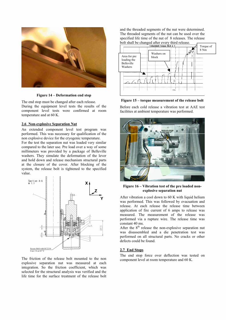
Figure 14 – Deformation end stop
The end stop must be changed after each release.During the equipment level tests the results of thecomponent level tests were confirmed at roomtemperature and at 60 K.
2.6 Non-explosive Separation NutAn extended component level test program wasperformed. This was necessary for qualification of thenon explosive device for the cryogenic temperature.For the test the separation nut was loaded very similarcompared to the later use. Pre load over a way of somemillimeters was provided by a package of Bellevillewashers. They simulate the deformation of the leverand hold down and release mechanism structural partsat the closure of the cover. After blocking of thesystem, the release bolt is tightened to the specifiedvalue.
X
Y
Z
Secure Bolt with EC2216Cure 2 h at 65 °C
The friction of the release bolt mounted to the nonexplosive separation nut was measured at eachintegration. So the friction coefficient, which wasselected for the structural analysis was verified and thelife time for the surface treatment of the release bolt
and the threaded segments of the nut were determined.The threaded segments of the nut can be used over thespecified life time of the nut of 8 releases. The releasebolt shall be changed after every third release.
Figure 15 – torque measurement of the release bolt
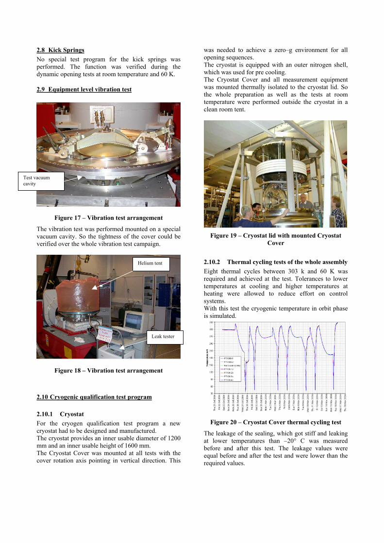
Before each cold release a vibration test at AAE testfacilities at ambient temperature was performed.
Figure 16 – Vibration test of the pre loaded non-explosive separation nut
After vibration a cool down to 60 K with liquid heliumwas performed. This was followed by evacuation andrelease. At each release the release time betweenapplication of fire current of 6 amps to release wasmeasured. The measurement of the release wasperformed via a rupture wire. The release time wasconstant 40 ms.After the 8th release the non-explosive separation nutwas disassembled and a die penetration test wasperformed on all structural parts. No cracks or otherdefects could be found.
2.7 End StopsThe end stop force over deflection was tested oncomponent level at room temperature and 60 K.
Area for preloading theBellevilleWashers
Washers onblock
Torque of8 Nm
2.8 Kick SpringsNo special test program for the kick springs wasperformed. The function was verified during thedynamic opening tests at room temperature and 60 K.
2.9 Equipment level vibration test
Figure 17 – Vibration test arrangement
The vibration test was performed mounted on a specialvacuum cavity. So the tightness of the cover could beverified over the whole vibration test campaign.
Figure 18 – Vibration test arrangement
2.10 Cryogenic qualification test program
2.10.1 CryostatFor the cryogen qualification test program a newcryostat had to be designed and manufactured.The cryostat provides an inner usable diameter of 1200mm and an inner usable height of 1600 mm.The Cryostat Cover was mounted at all tests with thecover rotation axis pointing in vertical direction. This
was needed to achieve a zero–g environment for allopening sequences.The cryostat is equipped with an outer nitrogen shell,which was used for pre cooling.The Cryostat Cover and all measurement equipmentwas mounted thermally isolated to the cryostat lid. Sothe whole preparation as well as the tests at roomtemperature were performed outside the cryostat in aclean room tent.
Figure 19 – Cryostat lid with mounted CryostatCover
2.10.2 Thermal cycling tests of the whole assemblyEight thermal cycles between 303 k and 60 K wasrequired and achieved at the test. Tolerances to lowertemperatures at cooling and higher temperatures atheating were allowed to reduce effort on controlsystems.With this test the cryogenic temperature in orbit phaseis simulated.
Figure 20 – Cryostat Cover thermal cycling test
The leakage of the sealing, which got stiff and leakingat lower temperatures than –20° C was measuredbefore and after this test. The leakage values wereequal before and after the test and were lower than therequired values.
Test vacuumcavity
Leak tester
Helium tent

2.10.3 Cooling loop thermal cycling testSix thermal cycles of the cover heat shield wereperformed when the Cryostat Cover was mounted onthe test vacuum vessel.This test simulated the ground test and storage phasewith internal temperature of the Cryostat of 70 ± 10 Kand external room temperature.
Figure 21 – Cooling Loop thermal cycling test
Figure 22 – Cover with mounted nitrongensupply lines
During this test it was verified, that the Coupling and the cover itself were isolated as no condensation or icing occurred.Connection/disconnection tests of the Suppwere performed verifying that no icing and clothe cooling loop can happen. Therefore the mof the Johnston Couplings on the cover are with non return valves, which provide high after de-coupling. So it can be avoided that h
streams into the cooling loop also at internal under-pressure.The supply lines are equipped with overpressure valvesto avoid overpressure in closed volumes. Only thecooling loop itself does not provide an overpressurevalve. Overpressure of the cooling loop is avoided bythe instruction, that disconnection of the supply lines isallowed at a cover heat shield (and supply line)temperature higher than 150 °C, which is always givenexcept during and directly after cooling. At this test, the cover is kept at 20 °C with cooleddown cover heat shield to 4 K. So the function of theiso-static mounts and the thermal isolation was alsoverified at this test.Thermal stress occurred also on the cooling loop andJohnston Couplings with a high temperature gradientand the material selection of stainless steel for theJohnston Couplings and aluminum for the coolingloop.Part of this test was also the verification of thetemperature uniformity over the cover heat shield ofrequired ±2 K at 80 K which could be achieved by theuse of a special aluminum alloy.
2.10.4 Dynamic opening tests at 60 K
On qualification level 5 cover opening tests wereperformed.
The cover was closed i.a.w. procedure, vibration tested,8x thermal cycled between 303 K and 60 K and openedvia electrical release at 60 K.
Supply andexhaust line
Electrical feed through for heatshield temperature signal
Internalpressuremeasure-ment
/helium
Johnstonwell that
ly Linesgging ofale partsequippedtightnessumid gas
Figure 23 – Cover dynamic opening sequence
After the first opening sequence only the non explosiveseparation nut was vibration tested and instead ofthermal cycling only cooling down to 60 K wasperformed.
The cover opened 5 times w/o any problem. A lot ofparameters were measured like release time of the non-explosive separation nut under varying current,opening time, force on the end stop springs, actuationof the limit switches for closed cover and for open

cover. The results were fully compliant with theanalysed values and the results of the component leveltests.
3. CONCLUSION
The qualification program was finished successfullyand the hardware was delivered for furtherqualification tests on system level.
Also the acceptance program for the proto-flight modelis nearly finished. The hardware is presently used bythe customer for closure of the cryostat and forinstrument calibration. It will be returned to AAE byend of the year for the thermal cycling test and for onecryogen release before final delivery.
4. LESSONS LEARNED
4.1 Cryogenic knowledge for hardwaredevelopmentAlthough AAE is supplier for cryogenic thermalhardware with excellent reputation some additionalknowledge concerning material selection and materialparameters for cryogenic application had to beinvestigated during the preliminary phase of theproject.
4.2 Establishment and conductance of a cryogenictest programSupport for the preparation and conductance of thecryogenic tests could be achieved by a partnership withthe Technical University of Vienna.Special skills for cryogenic testing especiallymeasurement under cryogenic conditions, control ofparameters and safety aspects could be gained.
4.3 Knowledge on spring actuated mechanismsDuring the preliminary phase the concept of the springactuated mechanisms could be improved further and isalready used at other projects for deployment units.The design for nearly friction free deployment allowsselection of actuators with lower pre tension. So highmargin of safety against structural failure can beachieved.
4.4 The non-explosive separation modification andqualificationThe non-explosive separation nut, which had to bemodified for cryogenic use could be made cryogeniccompatible after application of 6 changes. Afterincorporation of the new features the reliability wasproven by successful performance of the componentlevel and equipment level test program.
5. ACKNOWLEDGEMENT
We gratefully acknowledge the support of the customerEADS-Astrium GmbH (Friedrichshafen plant) in theperformance of this demanding project.