CryoCube F570n, F570h, F570hw - Eppendorf
70
nual 70n, F570h, F570hw EN) gmanual Register your instrument! www.eppendorf.com/myeppendorf CryoCube F570n, F570h, F570hw Operating manual
Transcript of CryoCube F570n, F570h, F570hw - Eppendorf

nual70n, F570h, F570hwEN)g manual
Register your instrument! www.eppendorf.com/myeppendorf
CryoCube F570n, F570h, F570hwOperating manual
Copyright© 2020 Eppendorf AG, Germany. All rights reserved, including graphics and images. No part of this publication may be reproduced without the prior permission of the copyright owner.
Eppendorf® and the Eppendorf Brand Design are registered trademarks of Eppendorf AG, Germany.
CryoCube® is a registered trademark of Eppendorf AG, Germany.
Registered trademarks and protected trademarks are not marked in all cases with ® or ™ in this manual.
U.S. Patents are listed on www.eppendorf.com/ip
004550117901-00/102020

3Table of contents
CryoCube F570n, F570h, F570hwEnglish (EN)
Table of contents
1 Operating instructions . . . . . . . . . . . . . . . . . . . . . . . . . . . . . . . . . . . . . . . . . . . . . . . . . . . . . . . . . . . . . . 71.1 Using this manual . . . . . . . . . . . . . . . . . . . . . . . . . . . . . . . . . . . . . . . . . . . . . . . . . . . . . . . . . . . . . 71.2 Danger symbols and danger levels . . . . . . . . . . . . . . . . . . . . . . . . . . . . . . . . . . . . . . . . . . . . . . . . 7
1.2.1 Danger symbols . . . . . . . . . . . . . . . . . . . . . . . . . . . . . . . . . . . . . . . . . . . . . . . . . . . . . . . 71.2.2 Danger levels. . . . . . . . . . . . . . . . . . . . . . . . . . . . . . . . . . . . . . . . . . . . . . . . . . . . . . . . . . 7
1.3 Symbols used . . . . . . . . . . . . . . . . . . . . . . . . . . . . . . . . . . . . . . . . . . . . . . . . . . . . . . . . . . . . . . . . 81.4 Version overview. . . . . . . . . . . . . . . . . . . . . . . . . . . . . . . . . . . . . . . . . . . . . . . . . . . . . . . . . . . . . . 8
2 Safety. . . . . . . . . . . . . . . . . . . . . . . . . . . . . . . . . . . . . . . . . . . . . . . . . . . . . . . . . . . . . . . . . . . . . . . . . . . . 92.1 Intended use . . . . . . . . . . . . . . . . . . . . . . . . . . . . . . . . . . . . . . . . . . . . . . . . . . . . . . . . . . . . . . . . . 92.2 Warnings for intended use . . . . . . . . . . . . . . . . . . . . . . . . . . . . . . . . . . . . . . . . . . . . . . . . . . . . . . 9
2.2.1 Devices with water cooling . . . . . . . . . . . . . . . . . . . . . . . . . . . . . . . . . . . . . . . . . . . . . . 102.2.2 Devices with flammable refrigerant . . . . . . . . . . . . . . . . . . . . . . . . . . . . . . . . . . . . . . . 10
2.3 User profile . . . . . . . . . . . . . . . . . . . . . . . . . . . . . . . . . . . . . . . . . . . . . . . . . . . . . . . . . . . . . . . . . 112.4 Personal protective equipment . . . . . . . . . . . . . . . . . . . . . . . . . . . . . . . . . . . . . . . . . . . . . . . . . . 112.5 Information on product liability . . . . . . . . . . . . . . . . . . . . . . . . . . . . . . . . . . . . . . . . . . . . . . . . . 112.6 Maintenance and repairs . . . . . . . . . . . . . . . . . . . . . . . . . . . . . . . . . . . . . . . . . . . . . . . . . . . . . . 112.7 Electromagnetic compatibility . . . . . . . . . . . . . . . . . . . . . . . . . . . . . . . . . . . . . . . . . . . . . . . . . . 12
2.7.1 Europe . . . . . . . . . . . . . . . . . . . . . . . . . . . . . . . . . . . . . . . . . . . . . . . . . . . . . . . . . . . . . . 122.7.2 U.S.A. . . . . . . . . . . . . . . . . . . . . . . . . . . . . . . . . . . . . . . . . . . . . . . . . . . . . . . . . . . . . . . 12
2.8 Warning symbols on the device . . . . . . . . . . . . . . . . . . . . . . . . . . . . . . . . . . . . . . . . . . . . . . . . . 12
3 Product description . . . . . . . . . . . . . . . . . . . . . . . . . . . . . . . . . . . . . . . . . . . . . . . . . . . . . . . . . . . . . . . 153.1 Product overview CryoCube F570n, CryoCube F570h and CryoCube F570hw . . . . . . . . . . . . . 15
3.1.1 General view . . . . . . . . . . . . . . . . . . . . . . . . . . . . . . . . . . . . . . . . . . . . . . . . . . . . . . . . . 153.1.2 Internal view . . . . . . . . . . . . . . . . . . . . . . . . . . . . . . . . . . . . . . . . . . . . . . . . . . . . . . . . . 173.1.3 Water connection . . . . . . . . . . . . . . . . . . . . . . . . . . . . . . . . . . . . . . . . . . . . . . . . . . . . . 183.1.4 Interfaces. . . . . . . . . . . . . . . . . . . . . . . . . . . . . . . . . . . . . . . . . . . . . . . . . . . . . . . . . . . . 18
3.2 Features. . . . . . . . . . . . . . . . . . . . . . . . . . . . . . . . . . . . . . . . . . . . . . . . . . . . . . . . . . . . . . . . . . . . 193.3 Models. . . . . . . . . . . . . . . . . . . . . . . . . . . . . . . . . . . . . . . . . . . . . . . . . . . . . . . . . . . . . . . . . . . . . 193.4 Alarms . . . . . . . . . . . . . . . . . . . . . . . . . . . . . . . . . . . . . . . . . . . . . . . . . . . . . . . . . . . . . . . . . . . . . 203.5 Delivery package. . . . . . . . . . . . . . . . . . . . . . . . . . . . . . . . . . . . . . . . . . . . . . . . . . . . . . . . . . . . . 213.6 Accessories . . . . . . . . . . . . . . . . . . . . . . . . . . . . . . . . . . . . . . . . . . . . . . . . . . . . . . . . . . . . . . . . . 21
3.6.1 Back-up systems . . . . . . . . . . . . . . . . . . . . . . . . . . . . . . . . . . . . . . . . . . . . . . . . . . . . . . 213.6.2 Chart recorder . . . . . . . . . . . . . . . . . . . . . . . . . . . . . . . . . . . . . . . . . . . . . . . . . . . . . . . . 213.6.3 Racks for ULT upright freezers . . . . . . . . . . . . . . . . . . . . . . . . . . . . . . . . . . . . . . . . . . . 213.6.4 Cardboard boxes and box dividers . . . . . . . . . . . . . . . . . . . . . . . . . . . . . . . . . . . . . . . . 223.6.5 Eppendorf Storage Box. . . . . . . . . . . . . . . . . . . . . . . . . . . . . . . . . . . . . . . . . . . . . . . . . 22
4 Installation . . . . . . . . . . . . . . . . . . . . . . . . . . . . . . . . . . . . . . . . . . . . . . . . . . . . . . . . . . . . . . . . . . . . . . 254.1 Selecting the location . . . . . . . . . . . . . . . . . . . . . . . . . . . . . . . . . . . . . . . . . . . . . . . . . . . . . . . . . 254.2 Preparing installation . . . . . . . . . . . . . . . . . . . . . . . . . . . . . . . . . . . . . . . . . . . . . . . . . . . . . . . . . 26
4.2.1 Unpacking the device . . . . . . . . . . . . . . . . . . . . . . . . . . . . . . . . . . . . . . . . . . . . . . . . . . 264.2.2 Checking the delivery . . . . . . . . . . . . . . . . . . . . . . . . . . . . . . . . . . . . . . . . . . . . . . . . . . 264.2.3 Transporting the device to the location . . . . . . . . . . . . . . . . . . . . . . . . . . . . . . . . . . . . 264.2.4 Setting up the device . . . . . . . . . . . . . . . . . . . . . . . . . . . . . . . . . . . . . . . . . . . . . . . . . . 27
4.3 Removing the transport clips from the inner shelves . . . . . . . . . . . . . . . . . . . . . . . . . . . . . . . . . 274.4 Changing a shelf position . . . . . . . . . . . . . . . . . . . . . . . . . . . . . . . . . . . . . . . . . . . . . . . . . . . . . . 28

Table of contentsCryoCube F570n, F570h, F570hwEnglish (EN)
4
4.5 Connecting the device to the voltage supply . . . . . . . . . . . . . . . . . . . . . . . . . . . . . . . . . . . . . . . 284.6 Connecting the device to the cooling water supply . . . . . . . . . . . . . . . . . . . . . . . . . . . . . . . . . . 29
4.6.1 Functional description . . . . . . . . . . . . . . . . . . . . . . . . . . . . . . . . . . . . . . . . . . . . . . . . . 294.6.2 Connecting to a cooling water supply without a water cooler . . . . . . . . . . . . . . . . . . . 294.6.3 Connecting to a cooling water supply with a water cooler. . . . . . . . . . . . . . . . . . . . . . 304.6.4 Connecting the device. . . . . . . . . . . . . . . . . . . . . . . . . . . . . . . . . . . . . . . . . . . . . . . . . . 31
4.7 Connecting the device to external systems. . . . . . . . . . . . . . . . . . . . . . . . . . . . . . . . . . . . . . . . . 314.7.1 Remote alarm interface. . . . . . . . . . . . . . . . . . . . . . . . . . . . . . . . . . . . . . . . . . . . . . . . . 314.7.2 RS-485 interface . . . . . . . . . . . . . . . . . . . . . . . . . . . . . . . . . . . . . . . . . . . . . . . . . . . . . . 32
4.8 Switching on the device . . . . . . . . . . . . . . . . . . . . . . . . . . . . . . . . . . . . . . . . . . . . . . . . . . . . . . . 324.8.1 Enabling the back-up circuit . . . . . . . . . . . . . . . . . . . . . . . . . . . . . . . . . . . . . . . . . . . . . 334.8.2 Switching the device on at the mains/power switch. . . . . . . . . . . . . . . . . . . . . . . . . . . 33
4.9 Basic device settings. . . . . . . . . . . . . . . . . . . . . . . . . . . . . . . . . . . . . . . . . . . . . . . . . . . . . . . . . . 34
5 Operation . . . . . . . . . . . . . . . . . . . . . . . . . . . . . . . . . . . . . . . . . . . . . . . . . . . . . . . . . . . . . . . . . . . . . . . 355.1 Opening the outer door. . . . . . . . . . . . . . . . . . . . . . . . . . . . . . . . . . . . . . . . . . . . . . . . . . . . . . . . 35
5.1.1 Opening the outer door. . . . . . . . . . . . . . . . . . . . . . . . . . . . . . . . . . . . . . . . . . . . . . . . . 355.2 Loading the device . . . . . . . . . . . . . . . . . . . . . . . . . . . . . . . . . . . . . . . . . . . . . . . . . . . . . . . . . . . 365.3 Locking the outer door . . . . . . . . . . . . . . . . . . . . . . . . . . . . . . . . . . . . . . . . . . . . . . . . . . . . . . . . 37
5.3.1 Locking the outer door . . . . . . . . . . . . . . . . . . . . . . . . . . . . . . . . . . . . . . . . . . . . . . . . . 375.4 Pressure compensation. . . . . . . . . . . . . . . . . . . . . . . . . . . . . . . . . . . . . . . . . . . . . . . . . . . . . . . . 385.5 Switching off the device . . . . . . . . . . . . . . . . . . . . . . . . . . . . . . . . . . . . . . . . . . . . . . . . . . . . . . . 38
5.5.1 Disabling the back-up circuit . . . . . . . . . . . . . . . . . . . . . . . . . . . . . . . . . . . . . . . . . . . . 385.5.2 Disconnecting the device from the voltage supply . . . . . . . . . . . . . . . . . . . . . . . . . . . . 395.5.3 Disconnecting the device from the cooling water supply. . . . . . . . . . . . . . . . . . . . . . . 39
6 Software . . . . . . . . . . . . . . . . . . . . . . . . . . . . . . . . . . . . . . . . . . . . . . . . . . . . . . . . . . . . . . . . . . . . . . . . 416.1 Overview of the control panel . . . . . . . . . . . . . . . . . . . . . . . . . . . . . . . . . . . . . . . . . . . . . . . . . . . 416.2 Checking parameters . . . . . . . . . . . . . . . . . . . . . . . . . . . . . . . . . . . . . . . . . . . . . . . . . . . . . . . . . 42
6.2.1 Displaying the set temperature for the interior of the device. . . . . . . . . . . . . . . . . . . . 426.2.2 Displaying the alarm limits for the interior temperature . . . . . . . . . . . . . . . . . . . . . . . 426.2.3 Displaying the alarm delay time . . . . . . . . . . . . . . . . . . . . . . . . . . . . . . . . . . . . . . . . . . 42
6.3 Working with a lock code . . . . . . . . . . . . . . . . . . . . . . . . . . . . . . . . . . . . . . . . . . . . . . . . . . . . . . 426.3.1 Unlocking and locking the device . . . . . . . . . . . . . . . . . . . . . . . . . . . . . . . . . . . . . . . . . 426.3.2 Activating and changing the lock code . . . . . . . . . . . . . . . . . . . . . . . . . . . . . . . . . . . . . 436.3.3 Deactivating the lock code . . . . . . . . . . . . . . . . . . . . . . . . . . . . . . . . . . . . . . . . . . . . . . 44
6.4 Programming parameters . . . . . . . . . . . . . . . . . . . . . . . . . . . . . . . . . . . . . . . . . . . . . . . . . . . . . . 446.4.1 Setting the set temperature for the interior . . . . . . . . . . . . . . . . . . . . . . . . . . . . . . . . . 446.4.2 Setting alarm limits . . . . . . . . . . . . . . . . . . . . . . . . . . . . . . . . . . . . . . . . . . . . . . . . . . . . 456.4.3 Setting an alarm delay time . . . . . . . . . . . . . . . . . . . . . . . . . . . . . . . . . . . . . . . . . . . . . 46
7 Maintenance . . . . . . . . . . . . . . . . . . . . . . . . . . . . . . . . . . . . . . . . . . . . . . . . . . . . . . . . . . . . . . . . . . . . . 477.1 Service schedule . . . . . . . . . . . . . . . . . . . . . . . . . . . . . . . . . . . . . . . . . . . . . . . . . . . . . . . . . . . . . 477.2 Defrosting the device . . . . . . . . . . . . . . . . . . . . . . . . . . . . . . . . . . . . . . . . . . . . . . . . . . . . . . . . . 477.3 Cleaning and decontamination . . . . . . . . . . . . . . . . . . . . . . . . . . . . . . . . . . . . . . . . . . . . . . . . . . 48
7.3.1 Cleaning the device. . . . . . . . . . . . . . . . . . . . . . . . . . . . . . . . . . . . . . . . . . . . . . . . . . . . 487.3.2 Cleaning and decontaminating the control panel . . . . . . . . . . . . . . . . . . . . . . . . . . . . . 487.3.3 Removing the inner door . . . . . . . . . . . . . . . . . . . . . . . . . . . . . . . . . . . . . . . . . . . . . . . 497.3.4 Installing the inner door again . . . . . . . . . . . . . . . . . . . . . . . . . . . . . . . . . . . . . . . . . . . 497.3.5 Cleaning the seals . . . . . . . . . . . . . . . . . . . . . . . . . . . . . . . . . . . . . . . . . . . . . . . . . . . . . 49
5Table of contents
CryoCube F570n, F570h, F570hwEnglish (EN)
7.3.6 Cleaning the air filter and the air intake grille . . . . . . . . . . . . . . . . . . . . . . . . . . . . . . . 507.3.7 Decontaminating the interior . . . . . . . . . . . . . . . . . . . . . . . . . . . . . . . . . . . . . . . . . . . . 50
7.4 Fuses . . . . . . . . . . . . . . . . . . . . . . . . . . . . . . . . . . . . . . . . . . . . . . . . . . . . . . . . . . . . . . . . . . . . . . 517.5 Checking the alarm . . . . . . . . . . . . . . . . . . . . . . . . . . . . . . . . . . . . . . . . . . . . . . . . . . . . . . . . . . . 51
7.5.1 Checking indicator lights and the signal tone. . . . . . . . . . . . . . . . . . . . . . . . . . . . . . . . 517.5.2 Checking the alarm in the case of a mains/power outage . . . . . . . . . . . . . . . . . . . . . . 51
7.6 Safety checklist . . . . . . . . . . . . . . . . . . . . . . . . . . . . . . . . . . . . . . . . . . . . . . . . . . . . . . . . . . . . . . 51
8 Troubleshooting . . . . . . . . . . . . . . . . . . . . . . . . . . . . . . . . . . . . . . . . . . . . . . . . . . . . . . . . . . . . . . . . . . 538.1 General errors . . . . . . . . . . . . . . . . . . . . . . . . . . . . . . . . . . . . . . . . . . . . . . . . . . . . . . . . . . . . . . . 53
8.1.1 Outer door . . . . . . . . . . . . . . . . . . . . . . . . . . . . . . . . . . . . . . . . . . . . . . . . . . . . . . . . . . . 538.1.2 Air filter . . . . . . . . . . . . . . . . . . . . . . . . . . . . . . . . . . . . . . . . . . . . . . . . . . . . . . . . . . . . . 538.1.3 Cooling water supply . . . . . . . . . . . . . . . . . . . . . . . . . . . . . . . . . . . . . . . . . . . . . . . . . . 53
8.2 Software error messages. . . . . . . . . . . . . . . . . . . . . . . . . . . . . . . . . . . . . . . . . . . . . . . . . . . . . . . 548.3 Mains/power outage . . . . . . . . . . . . . . . . . . . . . . . . . . . . . . . . . . . . . . . . . . . . . . . . . . . . . . . . . . 548.4 Heating up of the interior . . . . . . . . . . . . . . . . . . . . . . . . . . . . . . . . . . . . . . . . . . . . . . . . . . . . . . 54
9 Transport, storage and disposal . . . . . . . . . . . . . . . . . . . . . . . . . . . . . . . . . . . . . . . . . . . . . . . . . . . . . 559.1 Decommissioning . . . . . . . . . . . . . . . . . . . . . . . . . . . . . . . . . . . . . . . . . . . . . . . . . . . . . . . . . . . . 559.2 Transport . . . . . . . . . . . . . . . . . . . . . . . . . . . . . . . . . . . . . . . . . . . . . . . . . . . . . . . . . . . . . . . . . . . 55
9.2.1 Preparing the device for transport . . . . . . . . . . . . . . . . . . . . . . . . . . . . . . . . . . . . . . . . 569.2.2 Transporting the device . . . . . . . . . . . . . . . . . . . . . . . . . . . . . . . . . . . . . . . . . . . . . . . . 56
9.3 Shipment . . . . . . . . . . . . . . . . . . . . . . . . . . . . . . . . . . . . . . . . . . . . . . . . . . . . . . . . . . . . . . . . . . . 579.3.1 Shipping regulations . . . . . . . . . . . . . . . . . . . . . . . . . . . . . . . . . . . . . . . . . . . . . . . . . . . 579.3.2 Shipping the device. . . . . . . . . . . . . . . . . . . . . . . . . . . . . . . . . . . . . . . . . . . . . . . . . . . . 57
9.4 Disposal. . . . . . . . . . . . . . . . . . . . . . . . . . . . . . . . . . . . . . . . . . . . . . . . . . . . . . . . . . . . . . . . . . . . 58
10 Technical data. . . . . . . . . . . . . . . . . . . . . . . . . . . . . . . . . . . . . . . . . . . . . . . . . . . . . . . . . . . . . . . . . . . . 5910.1 Power supply. . . . . . . . . . . . . . . . . . . . . . . . . . . . . . . . . . . . . . . . . . . . . . . . . . . . . . . . . . . . . . . . 5910.2 Ambient conditions . . . . . . . . . . . . . . . . . . . . . . . . . . . . . . . . . . . . . . . . . . . . . . . . . . . . . . . . . . . 59
10.2.1 Operation. . . . . . . . . . . . . . . . . . . . . . . . . . . . . . . . . . . . . . . . . . . . . . . . . . . . . . . . . . . . 5910.3 Dimensions . . . . . . . . . . . . . . . . . . . . . . . . . . . . . . . . . . . . . . . . . . . . . . . . . . . . . . . . . . . . . . . . . 60
10.3.1 External dimensions . . . . . . . . . . . . . . . . . . . . . . . . . . . . . . . . . . . . . . . . . . . . . . . . . . . 6010.3.2 Internal dimensions. . . . . . . . . . . . . . . . . . . . . . . . . . . . . . . . . . . . . . . . . . . . . . . . . . . . 61
10.4 Weight . . . . . . . . . . . . . . . . . . . . . . . . . . . . . . . . . . . . . . . . . . . . . . . . . . . . . . . . . . . . . . . . . . . . . 6110.5 Interfaces. . . . . . . . . . . . . . . . . . . . . . . . . . . . . . . . . . . . . . . . . . . . . . . . . . . . . . . . . . . . . . . . . . . 6110.6 Cooling water supply . . . . . . . . . . . . . . . . . . . . . . . . . . . . . . . . . . . . . . . . . . . . . . . . . . . . . . . . . 62
10.6.1 Device connection. . . . . . . . . . . . . . . . . . . . . . . . . . . . . . . . . . . . . . . . . . . . . . . . . . . . . 6210.6.2 Building connection . . . . . . . . . . . . . . . . . . . . . . . . . . . . . . . . . . . . . . . . . . . . . . . . . . . 6210.6.3 Cooling water . . . . . . . . . . . . . . . . . . . . . . . . . . . . . . . . . . . . . . . . . . . . . . . . . . . . . . . . 6210.6.4 Cooling water hose . . . . . . . . . . . . . . . . . . . . . . . . . . . . . . . . . . . . . . . . . . . . . . . . . . . . 6210.6.5 Water filter . . . . . . . . . . . . . . . . . . . . . . . . . . . . . . . . . . . . . . . . . . . . . . . . . . . . . . . . . . 62
10.7 Temperature control . . . . . . . . . . . . . . . . . . . . . . . . . . . . . . . . . . . . . . . . . . . . . . . . . . . . . . . . . . 6310.7.1 Temperature range . . . . . . . . . . . . . . . . . . . . . . . . . . . . . . . . . . . . . . . . . . . . . . . . . . . . 6310.7.2 Cooling of the refrigeration cycle . . . . . . . . . . . . . . . . . . . . . . . . . . . . . . . . . . . . . . . . . 6310.7.3 Refrigerant . . . . . . . . . . . . . . . . . . . . . . . . . . . . . . . . . . . . . . . . . . . . . . . . . . . . . . . . . . 63
10.8 Additional specifications . . . . . . . . . . . . . . . . . . . . . . . . . . . . . . . . . . . . . . . . . . . . . . . . . . . . . . . 6310.8.1 Capacity. . . . . . . . . . . . . . . . . . . . . . . . . . . . . . . . . . . . . . . . . . . . . . . . . . . . . . . . . . . . . 6310.8.2 Material . . . . . . . . . . . . . . . . . . . . . . . . . . . . . . . . . . . . . . . . . . . . . . . . . . . . . . . . . . . . . 63

Table of contentsCryoCube F570n, F570h, F570hwEnglish (EN)
6
11 Ordering information . . . . . . . . . . . . . . . . . . . . . . . . . . . . . . . . . . . . . . . . . . . . . . . . . . . . . . . . . . . . . . 6511.1 Accessories . . . . . . . . . . . . . . . . . . . . . . . . . . . . . . . . . . . . . . . . . . . . . . . . . . . . . . . . . . . . . . . . . 65
11.1.1 Back-up systems . . . . . . . . . . . . . . . . . . . . . . . . . . . . . . . . . . . . . . . . . . . . . . . . . . . . . . 6511.1.2 Chart recorder . . . . . . . . . . . . . . . . . . . . . . . . . . . . . . . . . . . . . . . . . . . . . . . . . . . . . . . . 6511.1.3 Shelf . . . . . . . . . . . . . . . . . . . . . . . . . . . . . . . . . . . . . . . . . . . . . . . . . . . . . . . . . . . . . . . 6511.1.4 Racks for ULT upright freezers . . . . . . . . . . . . . . . . . . . . . . . . . . . . . . . . . . . . . . . . . . . 6611.1.5 Cardboard boxes and box dividers . . . . . . . . . . . . . . . . . . . . . . . . . . . . . . . . . . . . . . . . 6611.1.6 Eppendorf Storage Boxes . . . . . . . . . . . . . . . . . . . . . . . . . . . . . . . . . . . . . . . . . . . . . . . 6711.1.7 VisioNize system. . . . . . . . . . . . . . . . . . . . . . . . . . . . . . . . . . . . . . . . . . . . . . . . . . . . . . 67
Index . . . . . . . . . . . . . . . . . . . . . . . . . . . . . . . . . . . . . . . . . . . . . . . . . . . . . . . . . . . . . . . . . . . . . . . . . . . 68

7Operating instructions
CryoCube F570n, F570h, F570hwEnglish (EN)
1 Operating instructions1.1 Using this manual
Read this operating manual completely before using the device for the first time. Observe the instructions for use of the accessories where applicable.
This operating manual is part of the product. Please keep it in a place that is easily accessible.
Enclose this operating manual when transferring the device to third parties.
The current version of the operating manual for all available languages can be found on our webpage www.eppendorf.com/manuals.
1.2 Danger symbols and danger levels1.2.1 Danger symbols
The safety instructions in this manual have the following danger symbols and danger levels:
1.2.2 Danger levels
Risk of tipping over Electric shock
Highly flammable substances Explosive substances
Low temperatures Biohazard
Heavy load Risk of crushing
Hazard point Material damage
DANGER Will lead to severe injuries or death.
WARNING May lead to severe injuries or death.
CAUTION May lead to light to moderate injuries.
NOTICE May lead to material damage.

Operating instructionsCryoCube F570n, F570h, F570hwEnglish (EN)
8
1.3 Symbols used
1.4 Version overview
Depiction Meaning
1.2.
Actions in the specified order
Actions without a specified order
• List
Text Display or software texts
Additional information
Version Date Change
00 July 2020 Created new

9Safety
CryoCube F570n, F570h, F570hwEnglish (EN)
2 Safety2.1 Intended use
CryoCube ULT freezers are designed to provide an ultra-low temperature environment for storing scientific research materials. They allow for storage of samples at ultra-low temperatures of -50 °C to -86 °C and at a maximum ambient temperature of 32 °C.
All country-specific safety requirements for operating electrical equipment in laboratories must be observed.
2.2 Warnings for intended use
DANGER! Risk of severe injury from tipping the device over during transportIf the device tips over and falls on someone, that person sustains fatal injuries.
Transport the device with a sufficient number of helpers. Observe the transport instructions in the operating manual.
DANGER! Risk of severe injury from climbing onto the deviceThe device cannot carry the weight of a person. If the device tips over and falls on someone, that person sustains fatal injuries.The device may become damaged.
Do not climb onto the device. Do not pull yourself up on the device or the outer door.
WARNING! Risk of explosion
Do not operate the device in areas where work with explosive substances is carried out. Do not store explosive or highly reactive substances in the device. Do not use the device to store substances that may generate an explosive atmosphere. Do not store any aerogenic substances in the device, e.g., dry ice.
WARNING! Lethal voltages inside the device.If you touch any parts which are under high voltage you may experience an electric shock. Electric shocks cause heart injury and respiratory paralysis.
Ensure that the housing is closed and undamaged. Do not remove the housing. Ensure that no liquids can penetrate the device.Only authorized service staff may open the device.
SafetyCryoCube F570n, F570h, F570hwEnglish (EN)
10
2.2.1 Devices with water cooling
2.2.2 Devices with flammable refrigerant
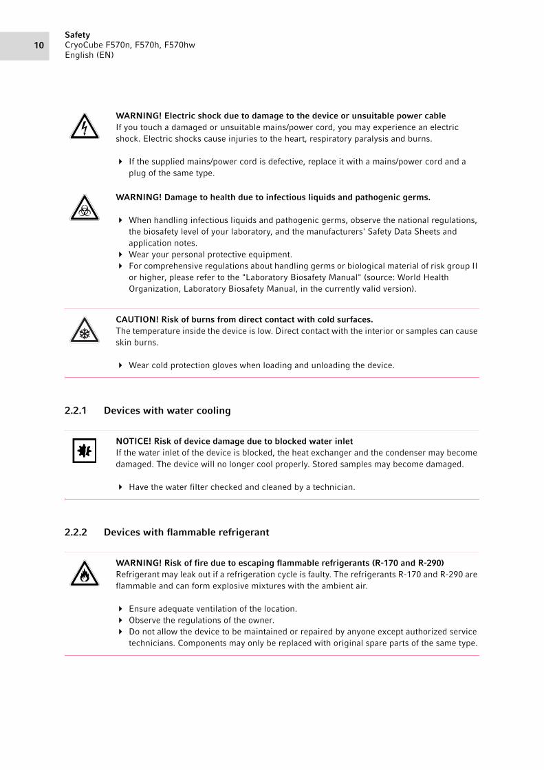
WARNING! Electric shock due to damage to the device or unsuitable power cableIf you touch a damaged or unsuitable mains/power cord, you may experience an electric shock. Electric shocks cause injuries to the heart, respiratory paralysis and burns.
If the supplied mains/power cord is defective, replace it with a mains/power cord and a plug of the same type.
WARNING! Damage to health due to infectious liquids and pathogenic germs.
When handling infectious liquids and pathogenic germs, observe the national regulations, the biosafety level of your laboratory, and the manufacturers' Safety Data Sheets and application notes.
Wear your personal protective equipment. For comprehensive regulations about handling germs or biological material of risk group II
or higher, please refer to the "Laboratory Biosafety Manual" (source: World Health Organization, Laboratory Biosafety Manual, in the currently valid version).
CAUTION! Risk of burns from direct contact with cold surfaces.The temperature inside the device is low. Direct contact with the interior or samples can cause skin burns.
Wear cold protection gloves when loading and unloading the device.
NOTICE! Risk of device damage due to blocked water inletIf the water inlet of the device is blocked, the heat exchanger and the condenser may become damaged. The device will no longer cool properly. Stored samples may become damaged.
Have the water filter checked and cleaned by a technician.
WARNING! Risk of fire due to escaping flammable refrigerants (R-170 and R-290)Refrigerant may leak out if a refrigeration cycle is faulty. The refrigerants R-170 and R-290 are flammable and can form explosive mixtures with the ambient air.
Ensure adequate ventilation of the location. Observe the regulations of the owner. Do not allow the device to be maintained or repaired by anyone except authorized service
technicians. Components may only be replaced with original spare parts of the same type.

11Safety
CryoCube F570n, F570h, F570hwEnglish (EN)
2.3 User profile
The device and accessories may only be operated by trained and skilled personnel.
Before using the device, read the operating manual and the instructions for use of the accessories carefully and familiarize yourself with the device's mode of operation.
2.4 Personal protective equipment
Personal protective equipment protects your life and your health.
Always wear the personal protective equipment required for the biosafety level and by the laboratory regulations.
Always wear protective clothing, protective gloves, and safety boots.
If additional protective equipment is required, this is indicated above the respective instruction.
2.5 Information on product liability
In the following cases, the designated protection of the device may be affected. The liability for any resulting damage or personal injury is then transferred to the owner:
• The device is not used in accordance with the operating manual.• The device is used outside of its intended use.• The device is used with accessories or consumables that are not recommended by Eppendorf.• The device is maintained or repaired by persons not authorized by Eppendorf AG.• The user makes unauthorized changes to the device.
2.6 Maintenance and repairs
Service technicians authorized by Eppendorf AG are appropriately trained and certified by Eppendorf AG.
Do not allow the device to be maintained by anyone except service technicians who are authorized by Eppendorf AG.
For more information, please contact your Eppendorf partner or visit www.eppendorf.com.
Do not allow the device to be maintained by anyone except service technicians who are accredited according to the national and local laws and safety regulations. Service technicians must hold valid certificates.
Australia, Queensland: the legal regulations state that service technicians require a valid gas work license for working on the refrigeration cycle.
Eppendorf AG uses high-quality components for the device which are manufactured especially for this purpose. These components ensure the safe function of the device. Eppendorf AG provides original spare parts for the service and repair of the device.
Components may only be replaced by original spare parts of the same type.

SafetyCryoCube F570n, F570h, F570hwEnglish (EN)
12
2.7 Electromagnetic compatibility2.7.1 Europe
This is a class A product. In a domestic environment this product may cause radio interference in which case the user may be required to take adequate measures.
2.7.2 U.S.A.
Any modification or changes made to this device, unless explicitly approved by Eppendorf, will invalidate the authorization of this device. Operation of an unauthorized device is prohibited under Section 302 of the Communications Act of 1934, as amended, and Subpart I of Part 2 of Chapter 47 of the Code of Federal Regulations.
This equipment has been tested and found to comply with the limits for a Class A digital device, pursuant to Part 15 of the FCC Rules. These limits are designed to provide reasonable protection against harmful interference when the equipment is operated in a commercial environment. This equipment generates, uses, and can radiate radio frequency energy and, if not installed and used in accordance with the operating manual, may cause harmful interference to radio communications. Operation of this equipment in a residential area is likely to cause harmful interference in which case the user will be required to correct the interference at his own expense.
2.8 Warning symbols on the device
Warning symbol Meaning
Information on the cooling water supply.
Danger from flammable refrigerant R-170.
Danger from flammable refrigerant R-290.
Min. Flow Requirement: 3.8 L/min 1US gal/min
Maximum Inlet Pressure: 10 bar 145 psig
Minimum Inlet Pressure: 1 bar 14.5 psig
Max. Supply Temperature: 25°C 77 °F
Min. Supply Temperature: 7 °C 45 °F
Connection Pipe Siz: 1/2“ BSP
WATER SUPPLY
R170
R290

13Safety
CryoCube F570n, F570h, F570hwEnglish (EN)
The device may only be serviced and repaired by a qualified refrigeration specialist who has been authorized by Eppendorf AG.If the device is serviced or repaired by an unauthorized person, liability on the part of Eppendorf AG shall cease immediately.
The device has passed the electrical safety test.
The device complies with the "Restriction of Hazardous Substances (RoHS)" directive 2011/65/EU.
Only connect the device to a mains/power connection with PE conductor.
Notice of a hazard point.Read the operating manual.
Risk of electric shock.Disconnect the mains/power cord from the voltage supply before removing the cover.
Risk of electric shock.
Warning symbol Meaning
THIS EPPENDORF FREEZER IS FITTED
WITH A CASCADE REFRIGERATION SYSTEM.
SERVICE AND REPAIRS MUST BE CARRIED OUT
BY A REFRIGERATION SPECIALIST APPROVED
BY YOUR SUPPLIER.
ANY REPAIRS CARRIED OUT BY UNAUTHORISED
ENGINEERS COULD CAUSE SERIOUS DAMAGE
TO THE SYSTEM AND MAY AFFECT YOUR WARRANTY.
ELECTRICAL SAFETY TESTDATE/INITIALS
APPL/REF No.
NEXT TEST DATE
PASSED
RoHS CompliantDirective 2011/65/EU
WARNINGTHIS EQUIPMENT
MUST BE EARTHED
DangerDisconnect the
mains supply beforeremoving this cover

SafetyCryoCube F570n, F570h, F570hwEnglish (EN)
14
The warning symbols inside the device can only be accessed by authorized service technicians.
Notice of a hazard point. Read the operating manual:Risk of crushing when closing the outer door.
Ice formation on seal
After prolonged or frequent opening of the freezer, humidity or ice may form on the door seal and the case frame. Ice formation may impair the function of the high-efficiency door seal.
• Wipe off humidity before closing the door.• Remove ice from the sealing surfaces.
Vacuum inside freezer
After closing the outer door, a vacuum can occur in the freezer. The outer door can no longer be opened.
• To speed up pressure compensation, press the auto vent button.
• Wait until pressure compensation has taken place, then operate the door handle.
Warning symbol Meaning
Danger due to flammable materials
Danger due to flammable gas, class 2
Warning symbol Meaning
FLAMMABLEGAS
2

15Product description
CryoCube F570n, F570h, F570hwEnglish (EN)
3 Product description3.1 Product overview CryoCube F570n, CryoCube F570h and CryoCube
F570hw3.1.1 General view
Abb. 3-1: Front and rear side
Fig. 3-1: Front and rear side
CryoCube
F570 n
1 2
12
11
8 7 6910
13
14
3
45

Product descriptionCryoCube F570n, F570h, F570hwEnglish (EN)
16
1 Access portFor external sensors
2 Access portFor external sensors or an optional back-up system
3 Switch locking plateLockable plate cover for the mains/power switch and battery switch
4 Battery switchFor activating the back-up circuit
5 Mains/power switchFor switching the device on and off
6 Interfaces
7 Space for an optional chart recorder
8 Air filter
9 Leveling foot
10 Heavy-duty castor
11 Name plate
12 Handle with cylinder lock
13 auto vent valveAutomatic pressure compensation
14 Operator panel with display

17Product description
CryoCube F570n, F570h, F570hwEnglish (EN)
3.1.2 Internal view
Abb. 3-2: Internal view
Fig. 3-2: Internal view
1 Shelf
2 Pilaster column
3 Inner door
1
2
3

Product descriptionCryoCube F570n, F570h, F570hwEnglish (EN)
18
3.1.3 Water connectionAbb. 3-3: Device with water cooling
Fig. 3-3: Device with water cooling
3.1.4 InterfacesAbb. 3-4: Interfaces
Fig. 3-4: Interfaces
Only devices which meet the requirements of IEC 950/EN 60950-1 (UL 1950) standards may be connected to the interface.
1 ConnectionWater outlet from the device
2 ConnectionWater inlet to the device
1 RS-485 serial interfaceConnection for internal use
2 Ethernet interfaceConnection to an external system
3 BMS remote alarm interfaceConnection to a building management system
4 Mains/power connectionConnection for the mains/power cord
1
2
4
3
2
1
19Product description
CryoCube F570n, F570h, F570hwEnglish (EN)
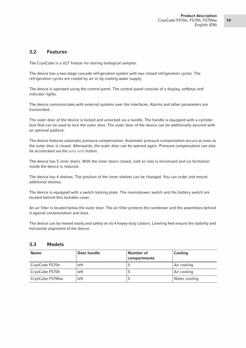
3.2 Features
The CryoCube is a ULT freezer for storing biological samples.
The device has a two-stage cascade refrigeration system with two closed refrigeration cycles. The refrigeration cycles are cooled by air or by cooling water supply.
The device is operated using the control panel. The control panel consists of a display, softkeys and indicator lights.
The device communicates with external systems over the interfaces. Alarms and other parameters are transmitted.
The outer door of the device is locked and unlocked via a handle. The handle is equipped with a cylinder lock that can be used to lock the outer door. The outer door of the device can be additionally secured with an optional padlock.
The device features automatic pressure compensation. Automatic pressure compensation occurs as soon as the outer door is closed. Afterwards, the outer door can be opened again. Pressure compensation can also be accelerated via the auto vent button.
The device has 5 inner doors. With the inner doors closed, cold air loss is minimized and ice formation inside the device is reduced.
The device has 4 shelves. The position of the inner shelves can be changed. You can order and mount additional shelves.
The device is equipped with a switch locking plate. The mains/power switch and the battery switch are located behind this lockable cover.
An air filter is located below the outer door. The air filter protects the condenser and the assemblies behind it against contamination and dust.
The device can be moved easily and safely on its 4 heavy-duty castors. Leveling feet ensure the stability and horizontal alignment of the device.
3.3 Models
Name Door handle Number of compartments
Cooling
CryoCube F570n left 5 Air cooling
CryoCube F570h left 5 Air cooling
CryoCube F570hw left 5 Water cooling

Product descriptionCryoCube F570n, F570h, F570hwEnglish (EN)
20
3.4 Alarms
When a safety-relevant situation has been reached, the device triggers an alarm. The user must immediately eliminate the cause of the alarm.
Alarms consist of a signal tone on site, an indicator light on the control panel, an alarm message on the control panel and forwarding of the alarm to a building management system. As soon as the cause of the alarm has been eliminated, all alarm signals will stop.
Alarm: Interior temperature• The temperature in the interior exceeds the alarm limit for the maximum or minimum temperature in
the interior.• The alarm is triggered when the delay time has elapsed. The delay time can be defined.• The signal tone sounds on the device.• The temp alarm indicator light lights up.• The alarm is forwarded to a building management system.• The alarm cannot be deactivated.
Alarm: Mains/power outage• The mains/power supply to the device is interrupted. The battery back-up circuit is switched on and
triggers the alarm.• The signal tone sounds on the device.• The power fail indicator light lights up.• The display shows the interior temperature and flashes at intervals of 10 s.• The alarm is forwarded to a building management system.• The alarm cannot be deactivated.
Alarm: Battery• The battery voltage is too low.• The battery-low indicator light lights up.• The alarm cannot be deactivated.
Alarm: System error• The signal tone sounds on the device.• The fault indicator light lights up.• The alarm cannot be deactivated.
Alarm: Clean the air filter• The air filter has to be cleaned.• The filter-clean indicator light flashes.• The alarm cannot be deactivated.

21Product description
CryoCube F570n, F570h, F570hwEnglish (EN)
3.5 Delivery package
Your device has been equipped according to your specifications.
Check the exact delivery package based on your delivery note.
3.6 Accessories
Optional accessories can be ordered separately. Information regarding accessories is available on our webpage: www.eppendorf.com.
3.6.1 Back-up systems
In the event of a mains/power outage, the battery-powered back-up system will start and cool the interior for a limited period of time. The back-up system is connected through the access port.
The following back-up systems are available:• CO2 back-up system for temperatures from -50 °C to -70 °C.
• LN2 back-up system for temperatures down to -85 °C.
3.6.2 Chart recorder
The chart recorder records the interior temperature on a disk over a period of 7 days. The port for connection of the chart recorder is available in the device.
Pens and disks for chart recorders are available.
3.6.3 Racks for ULT upright freezers
Racks serve to store and sort samples in boxes, microplates and deepwell plates.
Racks are placed on the inner shelves inside the device. The racks are used to store boxes. Stainless steel racks provide space for 136 mm × 136 mm boxes. Aluminum racks can be used to store boxes up to 133 mm × 133 mm.
Racks are available with drawers or with open sides. The design of the racks ensures an even temperature in the entire rack.

Product descriptionCryoCube F570n, F570h, F570hwEnglish (EN)
22
3.6.4 Cardboard boxes and box dividers
Abb. 3-5: Cardboard box and box divider
Fig. 3-5: Cardboard box and box divider
Cardboard boxes serve to store samples in tubes at temperatures down to -86 °C. Cardboard boxes have a waterproof coating.
To sort your samples, you can insert box dividers into the cardboard boxes. Eppendorf AG cardboard boxes and box dividers are compatible with each other.
3.6.5 Eppendorf Storage Box
Abb. 3-6: Eppendorf Storage Box
Fig. 3-6: Eppendorf Storage Box
Eppendorf Storage Boxes serve to store samples in tubes at temperatures down to -86 °C.
Eppendorf Storage Boxes are made of polypropylene (PP) and are autoclavable.

23Product description
CryoCube F570n, F570h, F570hwEnglish (EN)
3.6.6 Shelves
There are additional shelves available for the ULT upright freezer.
3.6.7 Temperature sensors
You can install an additional temperature sensor in the device to check the interior temperature using an external alarm system. The port for connection of the temperature sensor is available in the device.

Product descriptionCryoCube F570n, F570h, F570hwEnglish (EN)
24

25Installation
CryoCube F570n, F570h, F570hwEnglish (EN)
4 Installation4.1 Selecting the location
Abb. 4-1: FootprintCryoCube F570n
Fig. 4-1: FootprintCryoCube F570n
Information on ambient conditions, dimensions and weights can be found in the technical data.
Location in general• The ambient conditions match the specifications set out in the Technical data chapter.• The location is well ventilated or air-conditioned.• The location is not next to heat sources.• The location is protected against sparks and open fire.• The floor space corresponds to the technical data.• The floor is level, vibration-free and designed for the weight of the device.
Electrical connection• Mains/power connection in accordance with the name plate• The mains/power switch of the device and the disconnecting device of the power system circuit (e.g.,
residual current circuit breaker) are accessible during operation.
Cooling water supply• The building connection, cooling water and accessories match the specifications set out in the Technical
data chapter.

InstallationCryoCube F570n, F570h, F570hwEnglish (EN)
26
Air volume for devices with refrigerant R-290 or R-170
The devices contain the flammable refrigerants R-290 and R-170. Refrigerant may leak out through a leak in the refrigeration cycle. If the ambient air contains a certain concentration of the refrigerant, the oxygen in the air and the refrigerant will form a flammable gas-air mixture. You can prevent this from happening by ensuring the following
• Sufficient air volume• Controlled ventilation and venting of the location• The refrigeration cycles of the device contain less than 0.15 kg of refrigerant.• Access to and use of the room in which the device is located is not restricted according to EN 378.
4.2 Preparing installation4.2.1 Unpacking the device
1. Check the packaging for damage.
2. Unpack the device in accordance with the unpacking instructions.
4.2.2 Checking the delivery
1. Check the delivery for completeness.
2. Check the device and accessories for transport damage.
3. Do not commission the device if the packing or the device is damaged. Contact Eppendorf AG customer service or your Eppendorf partner.
4.2.3 Transporting the device to the location
Personal protective equipment• Protective clothing, safety shoes
Prerequisites
• The location meets the requirements.
Transport the device to the location (see Transport on p. 55).
Contact your safety officer for information on further requirements when installing the device.

27Installation
CryoCube F570n, F570h, F570hwEnglish (EN)
4.2.4 Setting up the device
Personal protective equipment• Protective clothing, safety shoes
Prerequisites• The device is in its intended position.
4.3 Removing the transport clips from the inner shelves
The device is supplied with the inner shelves installed. The inner shelves are secured for transport with transport clips. Each inner shelf is secured with 2 transport clips.
Tools and auxiliary equipment• Pliers
1. Attach anti-slipping pads to the underside of the leveling feet.
2. Rotate the leveling feet down.3. Remove the adhesive tape from the air intake
grille.
1. Use pliers to hold the lower part of the assembly clip.
2. Carefully turn the pliers clockwise for removing the assembly clips on the left side.
3. Carefully turn the pliers counter-clockwise for removing the assembly clips on the right side.
4. Take off the assembly clip.

InstallationCryoCube F570n, F570h, F570hwEnglish (EN)
28
4.4 Changing a shelf position
You can change the position of the shelves. You can mount additional shelves.
4.5 Connecting the device to the voltage supply
Prerequisites
• Mains/power connection in accordance with the name plate
1. If several mains/power cords are included, select the mains/power cord according to the mains/power supply voltage.
2. Connect the mains/power cord at the rear of the device.
3. Fasten the safety clamp.
If the device is moved, the mains/power cord cannot be pulled out of the device.
CAUTION! Risk of burns from direct contact with cold surfaces.The temperature inside the device is low. Direct contact with the interior or samples can cause skin burns.
Wear cold protection gloves when loading and unloading the device.
Abb. 4-2: Pilaster rail and shelf clip
Fig. 4-2: Pilaster rail and shelf clip
1. Insert the upper part of the shelf clip into the bore above.
2. Insert the bracket of the shelf clip into the bore of the pilaster rail.
3. You need 4 shelf clips to safely mount a shelf. Mount one shelf clip in each pilaster rail.
4. Place the shelf on the shelf clips.
WARNING! Risk due to incorrect voltage supply.
Only connect the device to voltage sources which correspond with the electrical requirements on the name plate.
Only use earth/grounded sockets with a protective earth (PE) conductor. Only use the mains/power cord supplied.

29Installation
CryoCube F570n, F570h, F570hwEnglish (EN)
4.6 Connecting the device to the cooling water supply4.6.1 Functional description
The cooling water absorbs the heat of the refrigerant in the condenser. This lowers the temperature of the refrigerant in the condenser. How much the refrigerant is cooled by is determined by the input temperature and volume flow of the cooling water.
The cooling water's input temperature can be measured at the water inlet. The volume flow is regulated via the water regulation valve.
The water regulation valve's factory settings assume a cooling water input temperature of approx. 20 °C and an ambient temperature of 21 °C – 23 °C. The valve regulates the volume flow so that the refrigerant leaves the condenser with a temperature of 25 °C. These settings allow for the greatest energy efficiency for the device.
4.6.2 Connecting to a cooling water supply without a water cooler
Abb. 4-3: Connection principle
Fig. 4-3: Connection principle
1 Water inlet to the device
2 Water outlet from the device
3 Water inlet to the cooling water supply
4 Water outlet from the cooling water supply
Device 1 Device 3 Device 4Device 2 Device 5
21 21 21 2121
4
3
InstallationCryoCube F570n, F570h, F570hwEnglish (EN)
30
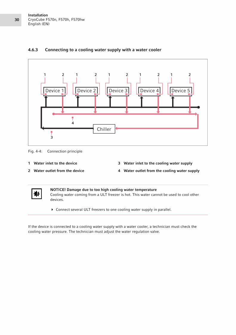
4.6.3 Connecting to a cooling water supply with a water cooler
Abb. 4-4: Connection principle
Fig. 4-4: Connection principle
If the device is connected to a cooling water supply with a water cooler, a technician must check the cooling water pressure. The technician must adjust the water regulation valve.
1 Water inlet to the device
2 Water outlet from the device
3 Water inlet to the cooling water supply
4 Water outlet from the cooling water supply
NOTICE! Damage due to too high cooling water temperatureCooling water coming from a ULT freezer is hot. This water cannot be used to cool other devices.
Connect several ULT freezers to one cooling water supply in parallel.
Device 1 Device 3 Device 4Device 2 Device 5
Chiller
3
4
21 21 21 2121

31Installation
CryoCube F570n, F570h, F570hwEnglish (EN)
4.6.4 Connecting the device
Accessories• Cooling water hose• Mounting material for the cooling water hose• Water filter (if necessary)• Stop valve (if necessary)• Pressure regulator
Prerequisites• The building connection and cooling water match the specifications set out in the Technical data
chapter.• The water regulation valve has been adjusted by a technician, if necessary.
Specialized knowledge and skills are required to work on the laboratory's water supply. Only qualified persons are allowed to work on the water supply. National and local safety regulations and legal provisions must be observed.
The owner is responsible for connecting the device to the water supply. The device must be connected according to local standards and regulations.
4.7 Connecting the device to external systems4.7.1 Remote alarm interface
1 Pin 1 and socket 1
2 Pin 2 and socket 2
3 Pin 3 and socket 3
213
1 2
3
InstallationCryoCube F570n, F570h, F570hwEnglish (EN)
32
You can connect the device to a building management system via the remote alarm interface.
The following alarms are forwarded to the building management system:• Mains/power outage• Interior temperature too high or too low
The plug is included in the delivery package. Connections must have double or reinforced insulation as described in DIN EN 61010-1.
4.7.2 RS-485 interface
The RS-485 interface is for internal purposes only.
4.8 Switching on the device
WARNING! Risk of electric shock due to damage to the device or to the mains/power cord.
Only switch on the device if the device and the mains/power cord are undamaged. Only operate devices which have been installed or repaired properly. In the event of danger, disconnect the device from the mains/power supply voltage.
Disconnect the mains/power plug from the device or the earth/grounded socket. Use the isolating device intended for this purpose (e.g., the emergency switch in the laboratory).
NOTICE! Damage to electronic components due to condensation. Condensate may form in the device when it has been transported from a cool environment to a warmer environment.
After installing the device, wait for at least 6 h. Only then connect the device to the mains/power line.
NOTICE! Improper door sealing due to iceHumidity inside the device causes ice formation. Ice causes damage to the seals of the inner and outer doors.
1. Dry the device completely, especially all seals.2. Switch on the device afterwards.

33Installation
CryoCube F570n, F570h, F570hwEnglish (EN)
4.8.1 Enabling the back-up circuit
The back-up circuit is battery-powered. In the event of a mains/power outage, the battery will supply power to the control panel and the alarm for 72 hours.
Tools and auxiliary equipment• Key for the switch locking plate
Prerequisites
• The device has been installed and connected according to the operating manual.• The device has been acclimatized for at least 6 h.
1. Unlock the switch locking plate and remove the cover.
2. Switch on the battery switch.
The back-up circuit is activated.• An alarm is triggered in the event of a mains/power outage.• In the event of a mains/power outage, power will still be supplied to the control panel.• The software settings are saved in the event of a mains/power outage.• The battery is charged with mains power. The battery is fully charged after approx. 24 hours.
3. Fit the cover and lock it.
4.8.2 Switching the device on at the mains/power switch
Tools and auxiliary equipment• Key for the switch locking plate
Prerequisites
• The device has been installed and connected according to the operating manual.• The device has been acclimatized for at least 6 h.• The interior, seals and doors are dry.• Devices with cooling water supply: The water inlet is open.
1. Unlock the switch locking plate and remove the cover.
2. Switch on the mains/power switch.
• The display shows the software version number.• The compressor starts running after a short time delay.
3. Fit the cover and lock it.

InstallationCryoCube F570n, F570h, F570hwEnglish (EN)
34
4.9 Basic device settings
For the initial operation of the device, set the following values.
1. Set the interior set temperature (see p. 44).
2. Set the alarm limits (see p. 45).
3. Set a delay time for the alarm (see p. 46).
4. To regulate and document access to the device, you can enable the user management (see p. 42).

35Operation
CryoCube F570n, F570h, F570hwEnglish (EN)
5 Operation5.1 Opening the outer door5.1.1 Opening the outer door
Prerequisites
• Pressure compensation has finished.
CAUTION! Hand injuriesThere are moving parts on the inside of the door handle.
Do not touch the inside of the door handle.
1. Unlock and remove the padlock, where applicable.
2. Unlock the cylinder lock, where applicable. To do so, insert the key into the cylinder lock, press it lightly and turn it.
3. Pull the door handle forward and down until it stops.
4. To open the outer door, pull the door handle towards you.

OperationCryoCube F570n, F570h, F570hwEnglish (EN)
36
5.2 Loading the device
Prerequisites
• Racks and accessories have been placed in the compartments.• Device, racks and accessories have reached the set temperature.
1. Open the outer door.
2. Open the inner door of the compartment in which you want to place the samples.
3. Place the samples in the device.
Information on the maximum carrying capacity of the inner shelves can be found in the technical data.
4. Close the inner door.
5. Close the outer door.
CAUTION! Risk of head injury due to open inner doorIf the upper inner doors are opened you can hit your head on the inner doors.
Only open one inner door at a time. Immediately close the inner door after completing your work.
NOTICE! Longer pull-down time because the device is loaded too earlyThe pull-down time is the time needed for the device to cool the interior from the ambient temperature to the set temperature.If you load the device during the cooling phase, the pull-down time will be longer. The pull-down time specified in the technical data cannot be achieved.
1. Allow the device to cool down from ambient temperature to the set temperature.2. Place the samples in the device after the device has reached the set temperature.
The interior temperature of the device increases when loading it:• Outer and inner doors are open.• The sample temperature differs from the interior temperature.
To minimize the temperature increase in the interior, load the device step by step.

37Operation
CryoCube F570n, F570h, F570hwEnglish (EN)
5.3 Locking the outer door5.3.1 Locking the outer door
CAUTION! Risk of hand being crushed when closing the outer door
Do not place your fingers between the device and the outer door. Lock the door handle slowly and carefully.
CAUTION! Risk of fingers being crushed when closing the inner doors.Incorrect handling of the inner doors can cause crushing injuries.
Only grasp the inner doors by the handle. Always open only one inner door.
NOTICE! Damage to the door handle due to incorrect closing of the outer door.Closing the outer door while the door handle is in the upright position damages the door handle.
1. Pull the door handle forward and down first.2. Then close the outer door.
1. Close the outer door.2. Lock the outer door. To do so, press the door
handle up.Automatic pressure compensation takes place as soon as the outer door is closed.
3. Check if the door handle is engaged in locked position.
4. Lock the cylinder lock, where applicable. To do so, insert the key into the cylinder lock, press it lightly and turn it
5. Mount the padlock and lock it, where applicable.
If the door handle is not properly engaged and there is negative pressure in the interior, the outer door appears to be closed. However, as soon as the negative pressure is compensated, the outer door can be opened again.

OperationCryoCube F570n, F570h, F570hwEnglish (EN)
38
5.4 Pressure compensation
If you leave the outer door open for a while, the temperature in the interior will increase. After closing the outer door, the air in the interior will cool down and the atmospheric pressure will decrease. Negative pressure may occur in the device. If negative pressure occurs, the outer door can no longer be opened.
Pressure compensation takes place automatically to reestablish ambient pressure in the device. Pressure compensation starts as soon as the outer door is closed.
To speed up pressure compensation, press the auto vent valve.
With the auto vent valve, pressure compensation takes 1 min – 2 min.
5.5 Switching off the device
5.5.1 Disabling the back-up circuit
Tools and auxiliary equipment• Key for the switch locking plate
1. Unlock the switch locking plate and remove the cover.
2. Switch off the battery switch.
The back-up circuit is disabled.• No alarm is triggered in the event of a mains/power outage.• During a mains/power outage, there will be no power supply to the control panel.• The battery is not charged.
WARNING! Risk of electric shock due to damage to the device or to the mains/power cord.
Only switch on the device if the device and the mains/power cord are undamaged. Only operate devices which have been installed or repaired properly. In the event of danger, disconnect the device from the mains/power supply voltage.
Disconnect the mains/power plug from the device or the earth/grounded socket. Use the isolating device intended for this purpose (e.g., the emergency switch in the laboratory).

39Operation
CryoCube F570n, F570h, F570hwEnglish (EN)
5.5.2 Disconnecting the device from the voltage supply
Tools and auxiliary equipment• Key for the switch locking plate
1. Unlock the switch locking plate and remove the cover.
2. Switch off the battery switch.
The back-up circuit is disabled.• No alarm is triggered in the event of a mains/power outage.• During a mains/power outage, there will be no power supply to the control panel.• The battery is not charged.
3. Switch off the mains/power switch.
5.5.3 Disconnecting the device from the cooling water supply
Close the water inlet.

OperationCryoCube F570n, F570h, F570hwEnglish (EN)
40

41Software
CryoCube F570n, F570h, F570hwEnglish (EN)
6 Software6.1 Overview of the control panel
Abb. 6-1: Control panel
Fig. 6-1: Control panel
1 auto vent valveFor ULT upright freezers onlyAutomatic pressure compensation
2 DisplayDuring operation the display shows the actual temperature in the interior.
3 Numerical keysAccess functions. Enter values.
4 C keyDelete entry.
5 E keyConfirm the entry.
6 alarm test mute softkeyDeactivate the signal tone Test the signal tone.
7 code change softkeyChange the lock code.
8 lock softkeyLock or unlock the control panel.
9 high alarm softkeyDisplay and adjust the alarm limit for the maximum interior temperature.
10 low alarm softkeyDisplay and adjust the alarm limit for the minimum interior temperature.
11 set temp softkeyDisplay and adjust the set interior temperature.
12 battery-low indicator lightLights up or flashes if the voltage in the back-up circuit is too low.Lights up if no mains/power supply voltage is available.
13 fault indicator lightLights up when a system error has occurred.
14 filter clean indicator lightLights up if the air filter needs to be cleaned.
15 power fail indicator lightFlashes if no mains/power supply voltage is supplied to the device.The signal tone sounds while the indicator light is flashing.
16 temp alarm indicator lightLights up if an alarm limit for the interior temperature has been exceeded.
17 remote control indicator lightLights up if the device is controlled by means of a computer.
2 3 4 5
67891011131417 121516
1

SoftwareCryoCube F570n, F570h, F570hwEnglish (EN)
42
6.2 Checking parameters6.2.1 Displaying the set temperature for the interior of the device
Press the set temp softkey.
The set temperature for the interior of the device is displayed.The factory setting is -80 °C.
6.2.2 Displaying the alarm limits for the interior temperature
To display the alarm limit for the maximum interior temperature, press the high alarm softkey.
To display the alarm limit for the minimum interior temperature, press the low alarm softkey.
The display shows the alarm limit.
6.2.3 Displaying the alarm delay time
To display the delay time for the on-site alarm, press the 8 softkey.
To display the delay time for the remote alarm, press the 9 softkey.
The delay time is displayed.
6.3 Working with a lock code
To prevent unauthorized programming of the device, you can use a four-digit lock code.
6.3.1 Unlocking and locking the device
Unlocking the device
Prerequisites
• The lock code is activated.
1. Press the lock softkey.
If the lock indicator light flashes, a lock code has been set.
2. Enter the lock code.
The actual temperature is displayed. The lock indicator light glows. The device is in programming mode. The parameters can be changed.

43Software
CryoCube F570n, F570h, F570hwEnglish (EN)
Locking the device
Prerequisites
• The lock code is activated.
3. After programming is completed, press the lock softkey.
The lock indicator light goes out. The device is no longer in programming mode. The parameters are saved.
6.3.2 Activating and changing the lock code
In the factory setting, the lock code is deactivated. To activate or change the lock code, proceed as follows.
1. Press the lock softkey.
2. When the lock indicator light flashes, enter the lock code.
The lock indicator light glows. The device is in programming mode. The parameters can be changed.
3. Press the code change softkey.
The code change indicator light flashes. The display is empty.
4. Enter a lock code using the numerical keys.
The lock code is displayed.
5. Check the lock code on the display.
6. To delete the entry, press softkey C.
7. Confirm the entry. To do so, press softkey E.
The code change indicator light goes out.The new lock code is active.
8. Exit programming mode. To do so, press the lock softkey.
The lock indicator light goes out. The device is no longer in programming mode. The parameters are saved.
If you press a softkey, e.g., set temp, while the lock indicator light is flashing, ---- appears on the display. The control panel is locked.
NOTICE! No software access due to lost lock codeIf you lose the lock code, reprogramming of the device will no longer be possible. The lock code will have to be reset by an authorized service technician.
Keep the lock code in a safe place.

SoftwareCryoCube F570n, F570h, F570hwEnglish (EN)
44
6.3.3 Deactivating the lock code
To deactivate the lock code, set it to 0000.
1. Press the lock softkey.
The lock indicator light flashes.
2. Enter the current lock code.
The actual temperature is displayed.The lock indicator light glows. The device is in programming mode. The parameters can be changed.
3. Press the code change softkey.
The code change indicator light flashes. The display is empty.
4. Enter the lock code 0000 using the numerical keys.
Entering the lock code 0000 will deactivate the lock code.The lock code 0000 is displayed.
5. Check the lock code on the display.
6. To delete the entry, press softkey C.
7. Confirm the entry. To do so, press softkey E.
The code change indicator light goes out.The new lock code is deactivated.
8. Exit programming mode. To do so, press the lock softkey.
The lock indicator light goes out. The device is no longer in programming mode. The parameters are saved.
6.4 Programming parameters6.4.1 Setting the set temperature for the interior
You can set the set temperature for the interior of the device to a range from -50 °C to -86 °C.
Prerequisites
• The device is not protected by a lock code.
1. Press the lock softkey.
The lock indicator light lights up. The device is in programming mode. The parameters can be changed.
2. Press the set temp softkey.
The set temp indicator light flashes. 0 is displayed.
3. Enter the set temperature with the numerical keys.
The set temperature is displayed. The set temperature is displayed as a negative value automatically.
4. To delete the entry, press the C softkey.
5. Confirm the entry. To do so, press the E softkey.
The set temp indicator light goes out.
6. Exit programming mode. To do so, press the lock softkey.
The lock indicator light goes out. The parameters are saved.

45Software
CryoCube F570n, F570h, F570hwEnglish (EN)
6.4.2 Setting alarm limits
You can set alarm limits for the interior temperature. If the interior temperature exceeds an alarm limit, an alarm will be triggered.
Prerequisites
• The device is not protected by a lock code.
1. Press the lock softkey.
The lock indicator light lights up. The device is in programming mode. The parameters can be changed.
2. To set the alarm limit for the maximum interior temperature, press the high alarm softkey.
The high alarm indicator light flashes. The display shows 0.
3. To set the alarm limit for the minimum interior temperature, press the low alarm softkey.
The low alarm indicator light flashes. 0 is displayed.
4. Enter the alarm limit using the numerical keys.
The display shows the alarm limit.
5. To delete the entry, press the C softkey.
6. Confirm the entry. To do so, press the E softkey.
The high alarm indicator light goes out.
7. Exit programming mode. To do so, press the lock softkey.
The lock indicator light goes out. The parameters are saved.
Minimum value Maximum value
Alarm limit for the minimum temperature in the interior
-91 °C 5 °C below the set temperature
Alarm limit for the maximum temperature in the interior
5 °C above the set temperature -10 °C

SoftwareCryoCube F570n, F570h, F570hwEnglish (EN)
46
6.4.3 Setting an alarm delay time
You can set a delay time for the "Interior temperature too high" and "Interior temperature too low" alarms. The delay time can be set for the on-site alarm and the remote alarm.
If you set the delay time to 0 min, the delay time will automatically be set to 15 s.
Prerequisites
• The device is not protected by a lock code.
1. Press the lock softkey.
The lock indicator light lights up. The device is in programming mode. The parameters can be changed.
2. To set the delay for the on-site alarm, press the 8 softkey.
3. To set the delay for the remote alarm, press the 9 softkey.
PP is displayed.
4. Enter the delay time using the numerical keys.
The delay time is displayed.
5. To delete the entry, press the C softkey.
6. Confirm the entry. To do so, press the E softkey.
--- is displayed. The value is saved.
7. If the entered value is outside the limit values, EE is displayed. Repeat the entry.
8. Exit programming mode. To do so, press the lock softkey.
The lock indicator light goes out. The parameters are saved.
Minimum value Maximum value Factory setting
On-site alarm 0 min 40 min 30 min
Remote alarm 0 min 40 min 30 min

47Maintenance
CryoCube F570n, F570h, F570hwEnglish (EN)
7 Maintenance7.1 Service schedule
7.2 Defrosting the device
Tools and auxiliary equipment• Personal protective equipment: Cold protection gloves, protective goggles, dust protection mask• Material for absorbing the melted water• "Defrosting device" notice sign
Prerequisites
• The samples have been transferred to another ULT freezer.• The device is switched off and disconnected from the mains/power line (see p. 38).
1. Put up the notice sign.
2. Open the outer and inner doors.
3. Wait until the ice has thawed.
4. Wipe up the melted water.
5. Dry the device completely, especially all seals.
Service Service cycle
Defrost the device. As required
Clean the interior and exterior of the device. As required
Clean the seals. Once a month
Clean the air filter and the air intake grille. Every 3 months under normal ambient conditions.Clean more frequently if the surroundings are very dusty or dirty.
CAUTION! Risk of slipping due to melt waterPuddles may form on the laboratory floor when defrosting the device.
Wipe up melt water immediately.
NOTICE! Risk of device damage due to scraping off iceRemoving ice with a sharp object may damage the device.
Wait until the ice has thawed by itself.
NOTICE! Improper door sealing due to iceHumidity inside the device causes ice formation. Ice causes damage to the seals of the inner and outer doors.
1. Dry the device completely, especially all seals.2. Switch on the device afterwards.

MaintenanceCryoCube F570n, F570h, F570hwEnglish (EN)
48
7.3 Cleaning and decontamination
7.3.1 Cleaning the device
Tools and auxiliary equipment• Water• Mild cleaning agent• Soft, lint-free cloth
Prerequisites
• For cleaning the interior: The device is switched off and disconnected from the mains/power line.• The device is defrosted.
1. Moisten the lint-free cloth with water and cleaning agent.
2. Clean the surfaces.
7.3.2 Cleaning and decontaminating the control panel
Tools and auxiliary equipment• Laboratory cleaner• Lint-free cloth• Decontamination agent: 70 % ethanol, 1% sodium hypochlorite solution, Dismozon pur, Hexaquart S,
Biozid ZF or a decontamination agent made of 70 % isopropyl alcohol and 30 % distilled water
1. To lock the control panel, press the lock softkey.
2. Moisten the lint-free cloth with laboratory cleaner or disinfectant.
3. Wipe the control panel with the cloth.
4. Unlock the locked control panel.
DANGER! Electric shock.
Switch off the device and disconnect the mains/power plug before commencing any service or cleaning procedures.
NOTICE! Damage from the use of aggressive chemicals.
Do not use any aggressive chemicals on the device or its accessories, such as strong and weak bases, strong acids, acetone, formaldehyde, halogenated hydrocarbons or phenol.
If the device has been contaminated by aggressive chemicals, clean it immediately using a mild cleaning agent.

49Maintenance
CryoCube F570n, F570h, F570hwEnglish (EN)
7.3.3 Removing the inner door
Abb. 7-1: Lifting out the inner door
Fig. 7-1: Lifting out the inner door
1. Fully open the outer door of the freezer.
2. Fully open the inner door.
3. Lift the inner door out of the hinges and carefully set it aside.
4. Clean the inner door.
7.3.4 Installing the inner door again
1. Fully open the outer door of the freezer.
2. Fit the inner door on the hinge pins and close it.
3. Check that the inner door seal sits firmly around the edge of the freezer.
4. Close the outer door.
7.3.5 Cleaning the seals
Tools and auxiliary equipment• Dry soft lint-free cloth
1. Wipe the seal with a soft, lint-free cloth.
2. Wipe the contact surface for the seal with a soft, lint-free cloth.
1 Inner door 2 Lift-off hinge
1 2

MaintenanceCryoCube F570n, F570h, F570hwEnglish (EN)
50
7.3.6 Cleaning the air filter and the air intake grille
Tools and auxiliary equipment• Vacuum cleaner• Warm water
1. Loosen the rotary knobs on the air intake grille.
The air intake grille folds down.
2. Remove the air intake grille.
3. Clean the air intake grille with a vacuum cleaner or alternatively with a soft brush.
4. Remove the coarse dirt from the air filter by vacuuming or tapping it.
5. Clean the air filter with warm water.
6. Let the air filter dry.
7. Insert the air filter.
8. Insert the air intake grille and fold it upwards. Tighten the rotary knobs.
7.3.7 Decontaminating the interior
The interior is made of stainless steel.
Tools and auxiliary equipment• Decontamination agent consisting of 70 % isopropyl alcohol and 30 % distilled water• Soft, lint-free cloth
Prerequisites
• The device is switched off and disconnected from the mains/power line.• The device is defrosted.
1. Moisten the lint-free cloth with decontamination agent.
2. Clean the surfaces using a lint-free cloth.
The surfaces are coated with a decontamination agent.
WARNING! Risk of burns and electric shockWhen the air intake grille is disassembled, access to the refrigeration system is no longer secured. Parts of the refrigeration system are live and become very hot. Electric shock and burns may occur.
Do not reach through the opening.
NOTICE! Refrigeration failure due to blocked air filterIf the air filter is blocked, the refrigerant will not be liquefied. This will damage the compressor.
Regularly check that the air flow into the device is not obstructed.

51Maintenance
CryoCube F570n, F570h, F570hwEnglish (EN)
3. Allow the decontamination agent to take effect.
4. Wipe off the decontamination agent with deionized water.
5. Allow the surfaces to dry.
7.4 Fuses
Fuses may only be replaced by authorized service technicians. Users must not replace the fuses.
7.5 Checking the alarm7.5.1 Checking indicator lights and the signal tone
Press the alarm test/mute softkey.
As long as the alarm test/mute softkey is pressed, all indicator lights are lit. The signal tone sounds. The display shows 8888.
7.5.2 Checking the alarm in the case of a mains/power outage
Prerequisites
• The back-up circuit is activated.
Switch off the device using the mains/power switch.
The power fail indicator light lights up.The display shows the interior temperature and flashes at intervals of 10 s.The signal tone sounds on the device.If the device is connected to a building management system via the remote alarm interface, the alarm is forwarded to the building management system.
7.6 Safety checklist
1. Fill in the safety checklist prior to repair or service of the device.
2. Hand a copy of the safety checklist to the authorized service technician.

MaintenanceCryoCube F570n, F570h, F570hwEnglish (EN)
52

53Troubleshooting
CryoCube F570n, F570h, F570hwEnglish (EN)
8 Troubleshooting8.1 General errors
If you are unable to resolve the error with the suggested measures, please contact your Eppendorf partner. The address can be found on our website: www.eppendorf.com.
8.1.1 Outer door
8.1.2 Air filter
8.1.3 Cooling water supply
Problem Cause Solution
The outer door cannot be opened.
• The door handle is locked. Unlock the door handle.
• The auto vent valve is blocked. The negative pressure in the interior is preventing the outer door from being opened.
Wait until pressure compensation has taken place. Balancing the pressure takes 1 to 2 hours.
After opening the outer door, remove the ice from the auto vent valve.
The keyboard is not responding.
• The keyboard is faulty. Switch the device off and back on. Contact your Eppendorf partner.
Problem Cause Solution
The filter clean indicator light lights up.
• The air filter is contaminated. Clean the air filter.
Problem Cause Solution
The device is not in operation.
• The water inlet and outlet connections are reversed.
Connect the water inlet and outlet properly.

TroubleshootingCryoCube F570n, F570h, F570hwEnglish (EN)
54
8.2 Software error messages
8.3 Mains/power outage
During a mains/power outage, no mains/power supply is supplied to the device. The device will trigger the "Mains/power outage" alarm . All danger signals go out once the device is supplied with power again.
The interior temperature may rise during a longer mains/power outage. • If the interior temperature is below the alarm limit for the maximum temperature in the interior after the
mains/power outage, the device continues to operate normally. • If the interior temperature is above the alarm limit for the maximum interior temperature, the "Interior
temperature” alarm is triggered after the delay time has elapsed.
8.4 Heating up of the interior
In case of a mechanical or electrical defect, the temperature inside the device may rise after some time. The temperature inside the device rises when the doors of the device are open and warm ambient air enters the device.
When the temperature inside the device exceeds the alarm limit, the "Interior temperature" alarm is triggered.
Open the outer doors and inner doors as briefly as possible to avoid that the temperature inside the device rises. In case of a malfunction, the back-up systems keeps the interior temperature stable over a longer period of time.
Problem Cause Solution
Code E-01The device triggers an alarm.
• The temperature sensor for measuring the interior temperature does not work.
Contact your Eppendorf partner.
Code E-02The device triggers an alarm.
• The temperature sensor at the condenser does not work.
Code E-03The device triggers an alarm.
• The temperature sensor at the heat exchanger does not work.
Code E-04 • The temperature at the condenser is too high.
Clean the air filter. Establish an ambient temperature
that complies with the technical data. Contact your Eppendorf partner.

55Transport, storage and disposal
CryoCube F570n, F570h, F570hwEnglish (EN)
9 Transport, storage and disposal9.1 Decommissioning
Prerequisites
• Racks and samples have been transferred to another ULT freezer.
1. Disable the back-up circuit (see p. 38).
2. Disconnect the device from the voltage supply (see p. 39).
3. Remove the safety clamp of the mains/power cord. Remove the mains/power cord from the device.
4. Devices with cooling water supply: Close the water inlet. Drain cooling water from the device.
5. Defrost the device (see p. 47).
6. Decontaminate the device (see p. 48).
9.2 Transport
DANGER! Risk of severe injury from tipping the device over during transportIf the device tips over and falls on someone, that person sustains fatal injuries.
Transport the device with a sufficient number of helpers. Observe the transport instructions in the operating manual.
CAUTION! Risk of foot injury due to little ground clearanceFeet can easily get trapped under the device.
Wear safety shoes with steel toes.
NOTICE! Risk of device damage due to lifting the device without the original palletLifting the device without the original pallet will damage the base of the device.
1. Place the device on the original pallet.2. Secure the device.3. Use a transport aid to lift the device.
NOTICE! Damage to the compressor and refrigeration cycle during transportTilting the device or transporting it in a horizontal position will damage the compressors and the refrigeration cycle. Refrigerant and oil may leak out.Shocks may dislodge the compressors from the brackets.
Transport the device in upright position. Move the device with due caution and care. Do not knock the device into anything. Protect the device from impacts. After setting up the device, wait for 6 h before switching it on.
Transport, storage and disposalCryoCube F570n, F570h, F570hwEnglish (EN)
56
9.2.1 Preparing the device for transport
Tools and auxiliary equipment• Open-end wrench
Prerequisites
• Racks and samples have been transferred to another ULT freezer.
1. Secure the shelves with transport clips (see p. 27).
2. Disable the back-up circuit (see p. 38).
3. Disconnect the device from the voltage supply (see p. 39).
4. Remove the safety clamp of the mains/power cord. Remove the mains/power cord from the device.
5. Devices with cooling water supply: Close the water inlet.
6. Turn the leveling feet up with the open-end wrench.
9.2.2 Transporting the device
Personal protective equipment• Protective clothing, safety shoes
Tools and auxiliary equipment• Transport aid• Original pallet
On level ground
1. Grasp the device by the housing and wheel it to its new location.
Do not grasp the device by the door handle.
Sloping surfaces
2. Transport the device sideways over ramps.
3. Do not transport the device over ramps at an angle > 17 % (10°).
NOTICE! Damage to the door handle due to too high loadsPulling or pushing the device on the door handle during transport may damage the door handle.
Grip the device at the housing to pull or push it.
NOTICE! Transport damage to the control panelThe control panel protrudes from the door. The control panel may become damaged during transport.
Only transport the device with the transport protection attached to the control panel.

57Transport, storage and disposal
CryoCube F570n, F570h, F570hwEnglish (EN)
Narrow passageways
4. Open the door of the device 180°.
5. Transport the device, with one side panel to the front, through the passageway.
If the passageway is too narrow for the device, housing parts may have to be disassembled. Contact your local Eppendorf partner for more information.
Lifting the device
6. Wheel the device onto the original pallet in accordance with the unpacking instructions.
7. Secure the device.
8. Lift the device with a transport aid.
Outside of buildings
9. Lift the device, see step 6 – 8.
10.Transport the device to the new location using a transport aid.
The heavy-duty castors are not suitable for transport outside of buildings.
9.3 Shipment9.3.1 Shipping regulations
ULT freezers that contain more than 100 g of flammable refrigerant are classified as refrigerating machines containing flammable, non-toxic, liquefied gas (UN no. 3358).
The device contains more than 100 g of flammable refrigerant and must not be transported by air freight.
9.3.2 Shipping the device
If you need help to transport the device, contact the authorized service.
WARNING! Risk of personal injury due to contamination.People may get contaminated if you store or ship a contaminated device.
Clean and decontaminate the device before shipping or storage.
NOTICE! Risk of damage due to incorrect packing.Eppendorf AG is not liable for any damage caused by improper packing.
Only store and transport the device in its original packing. If you do not have the original packing, request the original packing from Eppendorf AG.
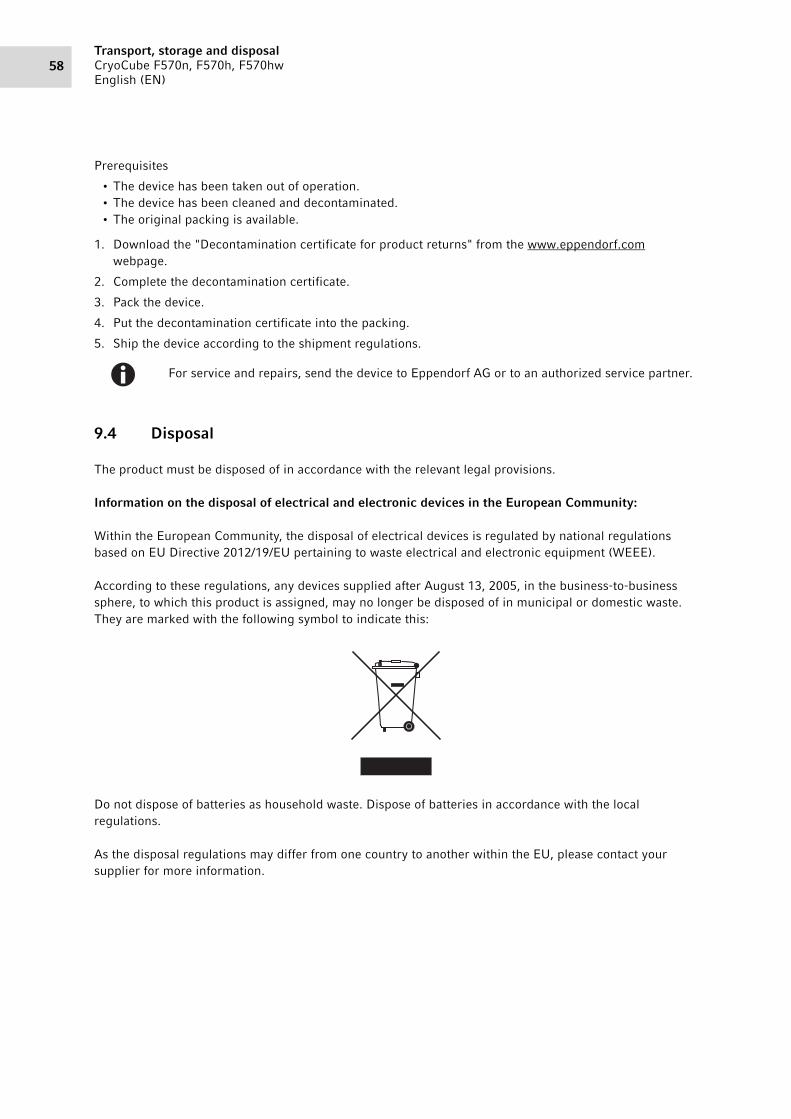
Transport, storage and disposalCryoCube F570n, F570h, F570hwEnglish (EN)
58
Prerequisites
• The device has been taken out of operation.• The device has been cleaned and decontaminated.• The original packing is available.
1. Download the "Decontamination certificate for product returns" from the www.eppendorf.com webpage.
2. Complete the decontamination certificate.
3. Pack the device.
4. Put the decontamination certificate into the packing.
5. Ship the device according to the shipment regulations.
9.4 Disposal
The product must be disposed of in accordance with the relevant legal provisions.
Information on the disposal of electrical and electronic devices in the European Community:
Within the European Community, the disposal of electrical devices is regulated by national regulations based on EU Directive 2012/19/EU pertaining to waste electrical and electronic equipment (WEEE).
According to these regulations, any devices supplied after August 13, 2005, in the business-to-business sphere, to which this product is assigned, may no longer be disposed of in municipal or domestic waste. They are marked with the following symbol to indicate this:
Do not dispose of batteries as household waste. Dispose of batteries in accordance with the local regulations.
As the disposal regulations may differ from one country to another within the EU, please contact your supplier for more information.
For service and repairs, send the device to Eppendorf AG or to an authorized service partner.
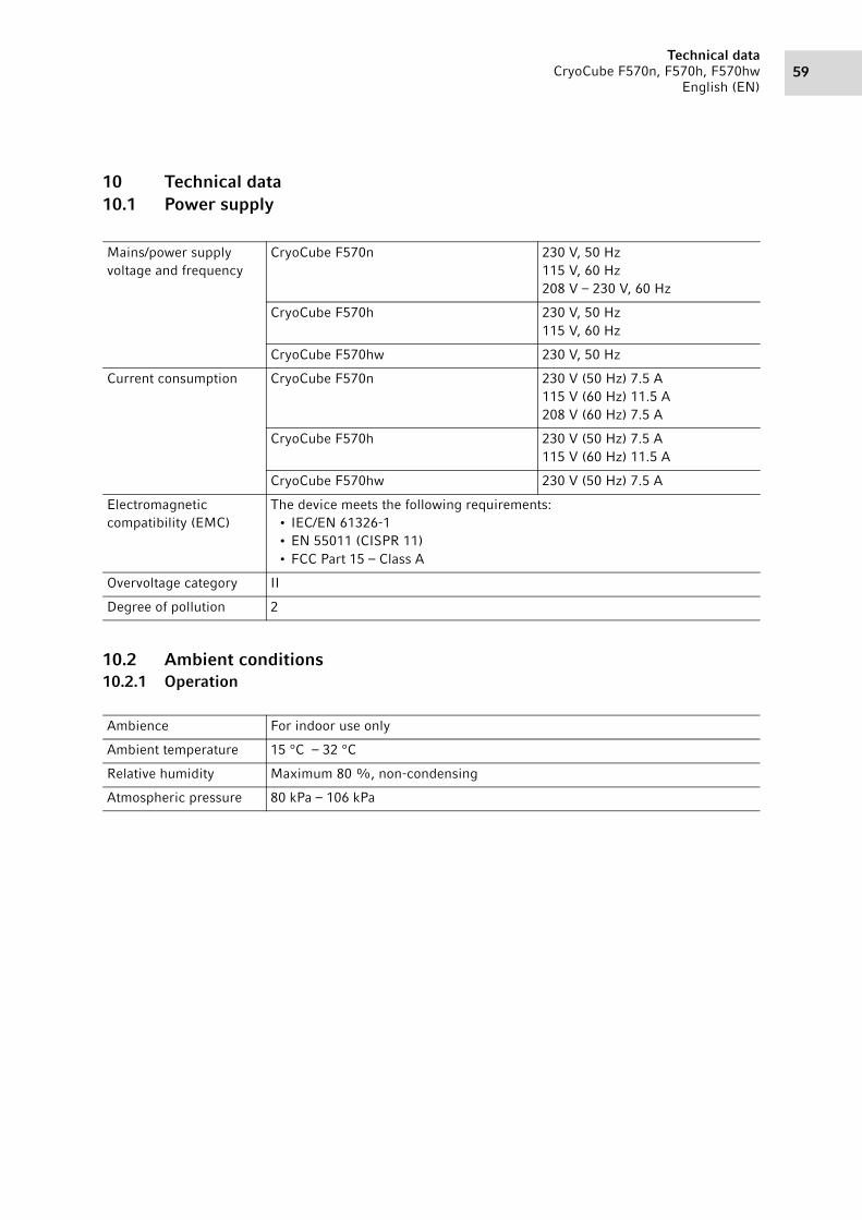
59Technical data
CryoCube F570n, F570h, F570hwEnglish (EN)
10 Technical data10.1 Power supply
10.2 Ambient conditions10.2.1 Operation
Mains/power supply voltage and frequency
CryoCube F570n 230 V, 50 Hz115 V, 60 Hz208 V – 230 V, 60 Hz
CryoCube F570h 230 V, 50 Hz115 V, 60 Hz
CryoCube F570hw 230 V, 50 Hz
Current consumption CryoCube F570n 230 V (50 Hz) 7.5 A115 V (60 Hz) 11.5 A208 V (60 Hz) 7.5 A
CryoCube F570h 230 V (50 Hz) 7.5 A115 V (60 Hz) 11.5 A
CryoCube F570hw 230 V (50 Hz) 7.5 A
Electromagnetic compatibility (EMC)
The device meets the following requirements:• IEC/EN 61326-1• EN 55011 (CISPR 11)• FCC Part 15 – Class A
Overvoltage category II
Degree of pollution 2
Ambience For indoor use only
Ambient temperature 15 °C – 32 °C
Relative humidity Maximum 80 %, non-condensing
Atmospheric pressure 80 kPa – 106 kPa

Technical dataCryoCube F570n, F570h, F570hwEnglish (EN)
60
10.3 Dimensions10.3.1 External dimensions
Abb. 10-1: External dimensions CryoCube F570n, CryoCube F570h and CryoCube F570hw
Fig. 10-1: External dimensions CryoCube F570n, CryoCube F570h and CryoCube F570hw
1940
mm
1094 mm 897 mm70 mm
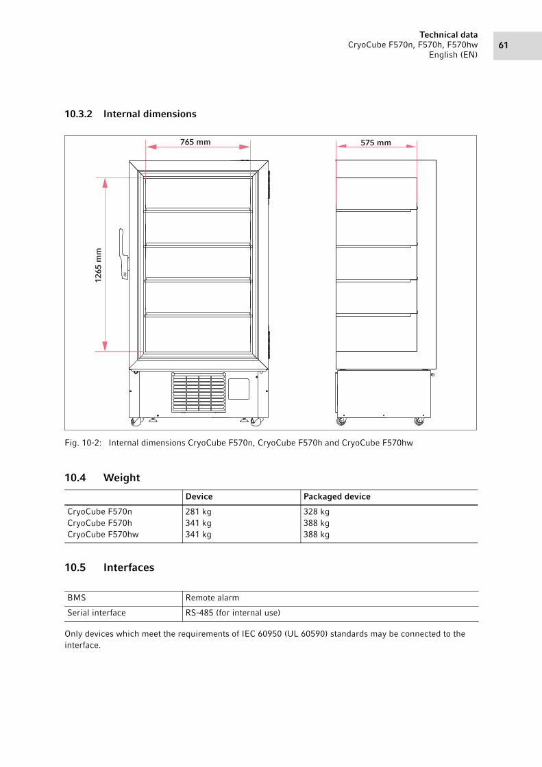
61Technical data
CryoCube F570n, F570h, F570hwEnglish (EN)
10.3.2 Internal dimensions
Abb. 10-2: Internal dimensions CryoCube F570n, CryoCube F570h and CryoCube F570hw
Fig. 10-2: Internal dimensions CryoCube F570n, CryoCube F570h and CryoCube F570hw
10.4 Weight
10.5 Interfaces
Only devices which meet the requirements of IEC 60950 (UL 60590) standards may be connected to the interface.
Device Packaged device
CryoCube F570nCryoCube F570hCryoCube F570hw
281 kg341 kg341 kg
328 kg388 kg388 kg
BMS Remote alarm
Serial interface RS-485 (for internal use)
765 mm 575 mm
1265
mm

Technical dataCryoCube F570n, F570h, F570hwEnglish (EN)
62
10.6 Cooling water supply10.6.1 Device connection
10.6.2 Building connection
10.6.3 Cooling water
10.6.4 Cooling water hose
Cooling water hoses are not included in the delivery package. Cooling water hoses and connecting elements are not available from Eppendorf AG and must be procured separately.
10.6.5 Water filter
If well water is used, mount the water filter in front of the device's water inlet.
Connection for water inlet and water outlet
Whitworth pipe thread15 mm × 12.7 mm (1/2" BSP) acc. to DIN 2999
Pressure at the water inlet 100 kPa – 1 000 kPa
Minimum pressure difference between water inlet and water outlet
50 Pa
Nominal cooling water supply volume flow rate
3.8 L/min
Connection for water inlet and water outlet
alternately 1/2" screw thread, 3/4" screw thread or bayonet coupling
Temperature at the water inlet 7 °C – 25 °C
Cooling water quality CleanFree from particles that could obstruct the flow through the valve or the heat exchanger.
Pressure resistance 1 000 kPa
Temperature resistance 30 °C or 35 °C
Length Distance from the building connection to the floor + 1 m
To reduce microbial growth and deposits, use oxygen-tight hoses.
Mesh size 0.25 mm (60 mesh)

63Technical data
CryoCube F570n, F570h, F570hwEnglish (EN)
10.7 Temperature control10.7.1 Temperature range
10.7.2 Cooling of the refrigeration cycle
10.7.3 Refrigerant
10.8 Additional specifications10.8.1 Capacity
10.8.2 Material
Setting range -50 °C to -86 °C
CryoCube F570nCryoCube F570h
Air cooling
CryoCube F570hw Water cooling
Device Refrigeration cycle 1 Refrigeration cycle 2
CryoCube F570n (115 V)CryoCube F570n(208 V)CryoCube F570n (230 V)
R-290R-290R-290
R-170R-170R-170
CryoCube F570h (115 V)CryoCube F570h (230 V)
R-290R-290
R-170R-170
CryoCube F570hw (230 V) R-290 R-170
Refrigerant Compounds
R-170 Ethane
R-290 Propane
CryoCube F570nCryoCube F570hCryoCube F570hw
570 L
Outer door insulation Vacuum insulation panels (only CryoCube F570h)Polyurethane foam
Device insulation Vacuum insulation panels (only CryoCube F570h)Polyurethane foam
Interior Stainless steel (304 2B)

Technical dataCryoCube F570n, F570h, F570hwEnglish (EN)
64

65Ordering information
CryoCube F570n, F570h, F570hwEnglish (EN)
11 Ordering information11.1 Accessories11.1.1 Back-up systems
11.1.2 Chart recorder
11.1.3 Shelf
Order no. (International)
Description
CO2 back-up systemU9043-0006 120 V - 220 V/60 HzU9043-0008 230 V/50 Hz
LN2 back-up systemU9044-0006 120 V - 220 V/60 HzU9044-0008 230 V/ 50 Hz
Order no. (International)
Description
Chart recorder type 1P0625-2100 Connection to mains/power supply in the ULT freezer
Discs for chart recorder type 1-100 °C – -50 °C
P0625-2110 60 piecesPens for chart recorder type 1
K0660-0051 3 pieces
Order no. (International)
Description
ShelfK0280-1030 1 piece
Shelf support for shelf post4 pieces
K0280-0550 CryoCube F570

Ordering informationCryoCube F570n, F570h, F570hwEnglish (EN)
66
11.1.4 Racks for ULT upright freezers
11.1.5 Cardboard boxes and box dividers
Order no. (International)
Description
Rack with drawersmaterial stainless steel
6001 022.210 for 16 boxes, box height 53 mm6001 022.910 for 12 boxes, box height 63 mm6001 022.310 for 8 boxes, box height 78 mm6001 022.410 for 8 boxes, box height 103 mm
Rack with side accessmaterial stainless steel
6001 021.210 for 16 boxes, box height 53 mm6001 021.910 for 12 boxes, box height 63 mm6001 021.310 for 8 boxes, box height 78 mm6001 021.410 for 8 boxes, box height 103 mm6001 021.110 with compartments for 24 deepwell plates up to 53 mm
Rack with drawersK0641-1900 Drawer height 53 mmK0641-1890 Drawer height 76 mmK0641-1880 Drawer height 102 mm
Order no. (International)
Description
Cardboard boxB50-SQ width 133 mm, depth 133 mm, height 50 mmB75-SQ width 133 mm, depth 133 mm, height 75 mmB95-SQ width 133 mm, depth 133 mm, height 100 mm
Box dividerD49 for 7 × 7 vessels, maximum vessel diameter 17.4 mmD64 for 8 × 8 vessels, maximum vessel diameter 15 mmD81 for 9 × 9 vessels, maximum vessel diameter 13 mmD100 for 10 × 10 vessels, maximum vessel diameter 11.8 mm

67Ordering information
CryoCube F570n, F570h, F570hwEnglish (EN)
11.1.6 Eppendorf Storage Boxes
11.1.7 VisioNize system
Further information about the Eppendorf VisioNize system can be found on the www.eppendorf.com webpage. Contact your local Eppendorf partner for more information.
Order no. (International)
Description
Eppendorf Storage Box 10 × 10, 2 inchheight 52.8 mm, for 100 cryogenic tubes with internal thread
0030 140.508 3 piecesEppendorf Storage Box 9 × 9, 2 inchheight 52.8 mm, for 81 screw cap (cryogenic) tubes 1 mL - 2 mL
0030 140.516 3 piecesEppendorf Storage Box 8 × 8, 2 inchheight 52.8 mm, for 64 micro test tubes 1 mL - 2 mL
0030 140.524 3 piecesEppendorf Storage Box 5 × 5, 2.5 inchheight 63.5 mm, for 25 micro test tubes 5 mL
0030 140.532 4 piecesEppendorf Storage Box 9 × 9, 3 inchheight 76.2 mm, for 81 screw cap (cryogenic) tubes 3 mL
0030 140.540 2 piecesEppendorf Storage Box 9 × 9, 4 inchheight 101.6 mm, for 81 screw cap (cryogenic) tubes 4 mL - 5 mL
0030 140.567 2 piecesEppendorf Storage Box 5 × 5, 5 inchheight 127 mm, for 25 conical tubes 15 mL
0030 140.583 2 piecesEppendorf Storage Box 3 × 3, 5 inchheight 127 mm, for 9 conical tubes 50 mL and 4 conical tubes 15 mL
0030 140.591 2 piecesEppendorf Storage Box 5 × 5, 3 inchheight 76.2 mm, for 25 screw cap tubes 5 mL
0030 140.613 2 piecesEppendorf Storage Box 3 × 3, 3.5 inchheight 88,9 mm, for 9 conical tubes 25 mL and 4 micro test tubes 5 mL
0030 140.729 2 pieces
IndexCryoCube F570n, F570h, F570hwEnglish (EN)
68
Index
A
Alarm.....................................................................20
B
Battery switchSwitching off ....................................................38Switching on ....................................................33
D
Degree of pollution................................................59
Device Switching off ....................................................39Switching on ....................................................33
Disposal .................................................................58
E
Electromagnetic compatibility (EMC) ...................59
S
Switching offBack-up circuit .................................................38Battery switch ..................................................38Device .............................................................39
Switching onBack-up circuit .................................................33Battery switch ..................................................33Device .............................................................33
T
Technical dataAmbient conditions..........................................59Operation .........................................................59
Temperature sensors.............................................23
W
Weight ...................................................................61

Evaluate Your Manual
Give us your feedback.www.eppendorf.com/manualfeedback
Your local distributor: www.eppendorf.com/contactEppendorf AG · Barkhausenweg 1 · 22339 Hamburg · [email protected] · www.eppendorf.com