Crusader ECM 07
143
MY 2007 ECM Training Diagnostic Supplement
-
Upload
giapy-andy -
Category
Documents
-
view
120 -
download
6
Transcript of Crusader ECM 07

MY 2007 ECMTraining
DiagnosticSupplement

THIS PAGE
INTENTIONALLY
LEFT BLANK

5.0/5.7/6.0/8.1L 2007 Drive-By-Wire T - 3
ECM-07 - CRUSADER
ECM DIAGNOSTIC TROUBLE CODES (DTC)DTC 279 Injector 7 Open or Short to Ground DTC 280 Injector 7 Coil Shorted DTC 282 Injector 8 Open or Short to Ground DTC 283 Injector 8 Coil Shorted DTC 326 Knock Sensor 1/2 Excessive Signal DTC 327 Knock Sensor 1/2 Sensor Open DTC 107 MAP Voltage Low DTC 108 MAP High Pressure DTC 2229 BP High Pressure DTC 129 BP Low Pressure DTC 111 IAT Higher Than Expected Stage 1 DTC 112 IAT Voltage Low DTC 113 IAT Voltage High DTC 127 IAT Higher Than Expected Stage 2 DTC 521 Oil Pressure Sender High Pressure DTC 522 Oil Pressure Sender Voltage Low DTC 523 Oil Pressure Sender Voltage High DTC 524 Oil Pressure Sender Low Pressure DTC 116 ECT Higher Than Expected Stage 1 DTC 117 ECT Voltage Low DTC 118 ECT Voltage High DTC 217 ECT Higher Than Expected Stage 2 DTC 2428 EGT Temperature High DTC 1542 Transmission Temperature High DTC 2122 FPP1 Voltage High DTC 2123 FPP1 Voltage Low DTC 2127 FPP2 Voltage Low DTC 2128 FPP2 Voltage High DTC 2115 FPP1 Higher Than IVS DTC 2139 FPP1 Lower than IVS DTC 2116 FPP2 Higher Than IVS DTC 2140 FPP2 Lower than IVS DTC 2126 FPP1 Higher than FPP2 DTC 2121 FPP1 Lower than FPP2 DTC 2130 IVS Stuck at idle, FPP1/2 match DTC 2131 IVS Stuck off idle, FPP1/2 match DTC 1121 FPP1/2 simultaneous voltages out of
range DTC 2120 FPP1 invalid voltage and FPP2 disagrees
with IVS DTC 2125 FPP1 invalid voltage and FPP2 disagrees
with IVS DTC 1122 FPP1/2 do not match each other or the IVS
DTC 601 Flash Checksum Invalid DTC 604 RAM Failure DTC 606 Microprocessor Failure - COP DTC 1612 RTI 1 Loss DTC 1613 RTI 2 Loss DTC 1614 RTI 3 Loss DTC 1615 A/D Loss DTC 1616 Invalid Interrupt DTC 642 Sensor Supply Voltage 1 Low DTC 643 Sensor Supply Voltage 1 High DTC 652 Sensor Supply Voltage 2 Low DTC 653 Sensor Supply Voltage 2 High DTC 1611 Sensor Supply Voltage 1/2 Simultaneous Out
Of Range DTC 2618 Tach Output Ground Short DTC 2619 Tach Output Short to Power DTC 627 Fuel Pump Relay Coil Open DTC 628 Fuel Pump Relay Control Ground Short DTC 629 Fuel Pump Relay Coil Short to Power DTC 685 Power Relay Coil Open DTC 686 Power Relay Control Ground Short DTC 687 Power Relay Coil Short to Power DTC 341 Cam Input Signal Noise DTC 342 Loss of Cam Input Signal DTC 219 RPM Above Max Governor DTC 1111 RPM Above Fuel Rev Limit DTC 1112 RPM Above Spark Rev Limit DTC 16 Never Crank Synced at Start DTC 336 Crank Input Signal Noise DTC 337 Crank Signal Loss DTC 261 Injector 1 Open or Short to Ground DTC 262 Injector 1 Coil Shorted DTC 264 Injector 2 Open or Short to Ground DTC 265 Injector 2 Coil Shorted DTC 267 Injector 3 Open or Short to Ground DTC 268 Injector 3 Coil Shorted DTC 270 Injector 4 Open or Short to Ground DTC 271 Injector 4 Coil Shorted DTC 273 Injector 5 Open or Short to Ground DTC 274 Injector 5 Coil Shorted DTC 276 Injector 6 Open or Short to Ground DTC 277 Injector 6 Coil Shorted

T - 4 2007 Drive-By-Wire 5.0/5.7/6.0/8.1L
ECM-07 - CRUSADER
ECM DIAGNOSTIC TROUBLE CODES (DTC)DTC 122 TPS1 Voltage Low DTC 123 TPS1 Voltage High DTC 222 TPS2 Voltage Low DTC 223 TPS2 Voltage High DTC 121 TPS1 Lower Than TPS2 DTC 221 TPS1 Higher Than TPS2 DTC 2111 Unable to reach Lower TPS DTC 2112 Unable to reach Higher TPS DTC 2135 TPS 1/2 Simultaneous Voltages Out Of Range DTC 562 Battery Voltage Low DTC 563 Battery Voltage High DTC 9999 Road Speed Loss of Input

5.0/5.7/6.0/8.1L 2007 Drive-By-Wire T - 5
ECM-07 - CRUSADER
PEG
15
45
75
16
46
76
30
60
9061
31
1
61
1
75
15 16
76 90
30
ECM 90 WAY CONNECTOR ECM PIN CKT(WIRE) CKT (WIRE) CIRCUIT DESCRIPTION NUMBER NUMBER COLOR 1 (OPEN) 2 (OPEN) 3 (OPEN) 4 (OPEN) 5 Throttle Position Sensor (TPS) 1 Input 6 Throttle Position Sensor (TPS) 2 Input 7 MAP Sensor Input 8 (OPEN) 9 Throttle Control Position (TCP) Sensor 1 Input 10 Throttle Control Position (TCP) Sensor 2 Input 11 Master/Slave Input
ECM Connector Pinout Identifi cation (1 of 4)

T - 6 2007 Drive-By-Wire 5.0/5.7/6.0/8.1L
ECM-07 - CRUSADER
ECM Connector Pinout Identifi cation (2 of 4)
61
1
75
15 16
76 90
30
J-1ECM 90 WAY CONNECTOR
ECM PIN CKT(WIRE) CKT (WIRE) CIRCUIT DESCRIPTION NUMBER NUMBER COLOR 12 Perfect Pass VGOV 13 CAN Bus 1 Termination 14 CAN Bus 1 (+) 15 CAN Bus 1 (-) 16 CAN Bus 2 (-) 17 CAN Bus 2 (+) 18 CAN Bus 2 Termination 19 Vref #1 (regulated 5.0 Vdc Output) 20 Ground Vref #1 (regulated 5.0Vdc Return) 21 Crankshaft Position Sensor (+) 22 Crankshaft Position Sensor (-) 23 Camshaft Position Sensor (+) 24 Camshaft Position Sensor (-) 25 Paddle Wheel (+) 26 Paddle Wheel (-) 27 Knock Sensor 1 (+) 28 Knock Sensor 1 (-) 29 Knock Sensor 2 (+) 30 Knock Sensor 2 (-) 31 Ignition Coil #1 (6.0/8.1L), (5.0/5.7L) 32 Ignition Coil #6 (6.0/8.1L) 33 Ignition Coil #8 (6.0/8.1L) 34 Ignition Coil #7 (6.0/8.1L) 35 Ignition Coil #5 (6.0/8.1L) 36 Ignition Coil #4 (6.0/8.1L) 37 Ignition Coil #2 (6.0/8.1L) 38 Ignition Coil #3 (6.0/8.1L) 39 Intake Air Temperature (IAT) Sensor Input 40 Engine Coolant Temperature (ECT) Sensor Input 41 Exhaust Gas Temperature (EGT) Switch 42 Throttle Control Position (TCP) Sensor Gain Select 43 Twin Engine Sync Select
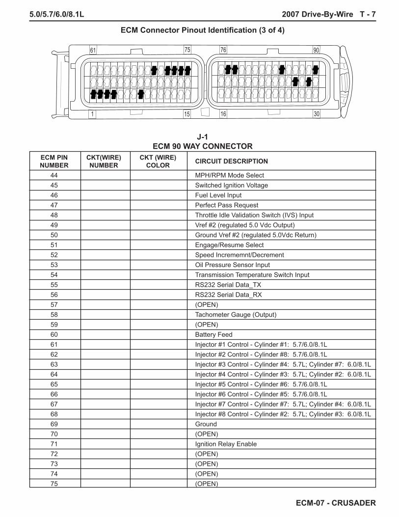
5.0/5.7/6.0/8.1L 2007 Drive-By-Wire T - 7
ECM-07 - CRUSADER
ECM Connector Pinout Identifi cation (3 of 4)
J-1ECM 90 WAY CONNECTOR
ECM PIN CKT(WIRE) CKT (WIRE) CIRCUIT DESCRIPTION NUMBER NUMBER COLOR 44 MPH/RPM Mode Select 45 Switched Ignition Voltage 46 Fuel Level Input 47 Perfect Pass Request 48 Throttle Idle Validation Switch (IVS) Input 49 Vref #2 (regulated 5.0 Vdc Output) 50 Ground Vref #2 (regulated 5.0Vdc Return) 51 Engage/Resume Select 52 Speed Incrememnt/Decrement 53 Oil Pressure Sensor Input 54 Transmission Temperature Switch Input 55 RS232 Serial Data_TX 56 RS232 Serial Data_RX 57 (OPEN) 58 Tachometer Gauge (Output) 59 (OPEN) 60 Battery Feed 61 Injector #1 Control - Cylinder #1: 5.7/6.0/8.1L 62 Injector #2 Control - Cylinder #8: 5.7/6.0/8.1L 63 Injector #3 Control - Cylinder #4: 5.7L; Cylinder #7: 6.0/8.1L 64 Injector #4 Control - Cylinder #3: 5.7L; Cylinder #2: 6.0/8.1L 65 Injector #5 Control - Cylinder #6: 5.7/6.0/8.1L 66 Injector #6 Control - Cylinder #5: 5.7/6.0/8.1L 67 Injector #7 Control - Cylinder #7: 5.7L; Cylinder #4: 6.0/8.1L 68 Injector #8 Control - Cylinder #2: 5.7L; Cylinder #3: 6.0/8.1L 69 Ground 70 (OPEN) 71 Ignition Relay Enable 72 (OPEN) 73 (OPEN) 74 (OPEN) 75 (OPEN)
61
1
75
15 16
76 90
30

T - 8 2007 Drive-By-Wire 5.0/5.7/6.0/8.1L
ECM-07 - CRUSADER
ECM Connector Pinout Identifi cation (4 of 4)
J-1ECM 90 WAY CONNECTOR
ECM PIN CKT(WIRE) CKT (WIRE) CIRCUIT DESCRIPTION NUMBER NUMBER COLOR 76 Buzzer 77 (OPEN) 78 (OPEN) 79 Battery Feed 80 Malfunction Indicator Lamp (MIL) Output 81 Ground 82 Drive-By-Wire (DBW) (+) 83 Drive-By-Wire (DBW) (-) 84 Fuel Pump Relay Enable 85 (OPEN) 86 Perfect Pass Status Lamp 87 Engine Coolant Temperature Gauge 88 Engine Oil Pressure Gauge 89 Sync Status Lamp 90 (OPEN)
61
1
75
15 16
76 90
30

5.0/5.7/6.0/8.1L 2007 Drive-By-Wire T - 9
ECM-07 - CRUSADER
ECM DIAGNOSTIC TROUBLE CODESThe following are ECM Internal Processor Diagnostic trouble codes. Should one or more of these codes be present; clear the codes, remove power from the ECM by disconnecting the battery power to the engine for at least 30 seconds, reconnect the battery and re-test. If the code returns replace the ECM. Any ECM failure code will result in a reduced throttle condition. The engine will not operate above 800 RPM. If equipped with a buzzer, the buzzer will sound for .5 sec then be off for .25 sec.DTC 601 Flash Checksum Invalid DTC 604 RAM Failure DTC 606 Microprocessor Failure - COP DTC 1612 RTI 1 Loss DTC 1613 RTI 2 Loss DTC 1614 RTI 3 Loss DTC 1615 A/D Loss DTC 1616 Invalid Interrupt
ECM 5V REFERENCE SUPPLY
Wire ECM Color Pin No. Function Lt Grn/Red 19 VREF #1 (5.0 Vdc) Blk/Lt Grn 20 VREF #1 (return) Lt Grn/Pur 49 VREF #2 (5.0 Vdc) Lt Grn/Blk 50 VREF #2 (return)
SENSOR VREF #1 VREF #2 MAP/IAT X OIL PRES. X CRANK X CAM X ECT X TPS X TCP X X
The following are ECM 5 Volt Reference Supply trouble codes. The 5 Volt Reference Supply provides the required operating voltage for the various sensors located on the engine. These codes may be present with various sensor codes also. Always verify that VREF #1 and #2 voltages and circuits are correct before troubleshooting the sensor code. If VREF #2 fails, the operator will have Idle Only operation of the throttle. Also, if equipped with a buzzer, the buzzer will sound for .5 sec and be off for .25 sec.DTC 642 Sensor Supply Voltage 1 Low - Sensor voltage output is less than 4.6 Vdc.DTC 643 Sensor Supply Voltage 1 High - Sensor voltage output is greater than 5.4 Vdc.DTC 652 Sensor Supply Voltage 2 Low - Sensor voltage output is less than 4.6 Vdc.DTC 653 Sensor Supply Voltage 2 High - Sensor voltage output is greater than 5.4 Vdc.DTC 1611 Sensor Supply Voltage 1/2 Simultaneous Out Of Range - Uses the same parameters as stated above.
ECM DIAGNOSTIC TROUBLE CODESThe following are ECM Diagnostic trouble codes for the Tach Output, ECM Pin 58. The Tach output is used by an instrument panel analog gauge or by the Perfect Pass speed control system (optional). Should one of these codes be present; clear the codes and one at a time, isolate the boat’s Tach gauge, then Perfect Pass System, from the engine harness and retest; if the code returns troubleshoot the engine harness for a short to ground or power, if no wiring problem is present replace the ECM. DTC 2618 Tach Output Ground Short DTC 2619 Tach Output Short to Power

T - 10 2007 Drive-By-Wire 5.0/5.7/6.0/8.1L
ECM-07 - CRUSADER
40
20
15
20
20
5
15
Electrical System Relay and Fuse Block
IGNITION RELAY: Controlled by the ECM (Pin 71). When it is energized, battery power will be supplied to the Ignition Module(s), Ignition Coil(s), and all eight Fuel Injectors. If the ingnition switch is left in the Key-ON-Engine OFF position for more than 15 seconds without trying to start the engine, the ECM will de-energize the Ignition Relay. Cycle the Ignition Switch OFF to ON or to Start Position to energize the Ignition Relay, again.ECM DIAGNOSTIC TROUBLE CODESDTC 685 Power Relay Coil Open DTC 686 Power Relay Control Ground Short DTC 687 Power Relay Coil Short to Power Troubleshoot wiring between relay socket pin 85 and ECM pin 71. Troubleshoot relay socket wiring for any shorts to ground or power, broken, pushed, or shorted pins. Replace Ignition Relay.STARTER RELAY: Controlled by the boat’s start circuit (Pin 7 of the 8-Pin Boat Interface Connector). When the Key is in the START position this relay will energize and apply battery voltage to the Starter Solenoid to enable the starter and crank the engine.STARTER FUSE - 20 AMP MAXI: Provides protection to the Starter Solenoid circuit. If the Starter Solenoid draws too much current or is shorted to ground this fuse will open. Note: The Starter Relay will still energize when the Key is in the START position when this fuse is open.PANEL FUSE - 40 AMP MAXI: Provides overload protection for the Boat Accessory devices that may be using this battery feed circuit (Pin 1 of the 2-Pin Boat Interface Connector). If this fuse is open, you may have a no start/no run condition if this battery feed is used to power the boat’s ignition key switch. However, many boats are wired such that when this fuse is open, it will only affect boat accessory device operation and the engine will continue to operate normally.FUEL PUMP FUSE - 20 AMP: This fuse provides overload protection for the Fuel Pump Relay, High Pressure Fuel Pump, Low Pressure Fuel Pump, and Remote Electric Fuel Solenoid (if equipped).ECM FUSE - 20 AMP: Provides overload protection for the ECM battery feed circuits; ECM pins 60 and 79.VSW - 5 AMP: Provides overload protection for the ECM Voltage Switched (Ignition voltage) circuit; ECM pin 45 (from pin 5 of the 8-Pin Boat Interface Connector).DIAGNOSTIC CONNECTOR - 15 AMP: Provides overload protection of the battery feed circuit (pin A of the Calibration Tool Connector and pin E of the Diagnostic Tool Connector) when a Diagnostic Scan/Calibration Tool is connected.IGNITION - 15 AMP: Provides overload protection for the Ignition Module(s), Ignition Coil(s), Fuel Injectors, and the Alternator’s regulator circuit Sense Input.
FUEL PUMP RELAY: Controlled by the ECM (Pin 84). When it is energized, the fuel pumps will run. At initial Key ON, the ECM will energize the relay for 2-4 seconds to prime the fuel system. Once the ECM recognizes the Crank Position Sensor signal the fuel pumps will remain on while the engine is running or until Key OFF.ECM DIAGNOSTIC TROUBLE CODESDTC 627 Fuel Pump Relay Coil Open DTC 628 Fuel Pump Relay Control Ground Short DTC 629 Fuel Pump Relay Coil Short to Power Troubleshoot wiring between relay socket pin 85 and ECM pin 84. Troubleshoot relay socket wiring for any shorts to ground or power, broken, pushed, or shorted pins. Replace Fuel Pump Relay.

5.0/5.7/6.0/8.1L 2007 Drive-By-Wire T - 11
ECM-07 - CRUSADER
Wire ECM Pin Color Pin No. Function A 19 VREF #1 (5.0 Vdc) B 24 CMP (-) C 23 CMP (+)
684840
Connector Part Information
• 12129946• 3-Way F Metri-Pack 150 Series Sealed
Camshaft Position (CMP) Sensor (8.1L)
Camshaft Position (CMP) Sensor (6.0L) Wire ECM Pin Color Pin No. Function A Gry/Brn 23 CMP (+) B Blk/Lt Grn 24 CMP (-) C Lt Grn/Red 19 VREF #1 (5.0 Vdc)
Camshaft Position (CMP) Sensor (5.7L) Wire ECM Pin Color Pin No. Function A Pur/Orn 24 CMP (-) B Gry/Brn 23 CMP (+) C Lt Grn/Red 19 VREF #1 (5.0 Vdc)
Camshaft Position (CMP) Sensor (8.1L)
ECM DIAGNOSTIC TROUBLE CODESTypically, with a Cam Position Sensor failure, you will have a no start condition. If the sensor fails while the engine is running, the MIL will be lit and engine operation will be normal until the engine is shut off, then it will not restart.DTC 341 Cam Input Signal Noise - ECM detects more than 1 re-sync or invalid cam signal within a 700 ms period of a cranking cycle. Possible loose or broken connection at the ECM or CMP or short to battery power on any of the CMP wiring. Verify wiring, connections at CMP and ECM - repair as required. Replace CMP.DTC 342 Loss of Cam Input Signal - ECM detects no CAM pulses above 100 RPM. Possible open, short to ground, or short to battery power on the CMP (+) signal path. Also, possible short to battery power on the CMP (-) signal path. Verify wiring, connections at CMP and ECM - repair as required. Replace CMP.
ADDITIONAL FAULTS THAT MAY BE ASSOCIATED WITH A DEFECTIVE CMP SENSOR OR SENSOR CIRCUITDTC 219 RPM Above Max Governor - ECM detects RPM above Max Governor. Typically this code will be accompanied by other codes, troubleshoot the other codes fi rst, if this code remains, replace the ECM.DTC 1111 RPM Above Fuel Rev Limit - ECM detects RPM above Max Governor. Fuel will be shut off to the engine. Typically this code will be accompanied by other codes, troubleshoot the other codes fi rst, if this code remains, replace the ECM.DTC 1112 RPM Above Spark Rev Limit - ECM detects RPM above Max Governor. Spark will be shut off to the engine. Typically this code will be accompanied by other codes, troubleshoot the other codes fi rst, if this code remains, replace the ECM.

T - 12 2007 Drive-By-Wire 5.0/5.7/6.0/8.1L
ECM-07 - CRUSADER
366117 Connector Part Information
• 15324165• 3-Way F Metri-Pack 150 Series Sealed
Crankshaft Position (CKP) Sensor (8.1L)
Wire ECM Pin Color Pin No. Function A Lt Grn/Red 19 VREF #1 (5.0 Vdc) B 22 CKP (-) C 21 CKP (+)
Crankshaft Position (CKP) Sensor (6.0L) Wire ECM Pin Color Pin No. Function A Pur/Wht 21 CKP (+) B Blk/Lt Grn 22 CKP (-) C Lt Grn/Red 19 VREF #1 (5.0 Vdc)
Crankshaft Position (CKP) Sensor (5.7L) Wire ECM Pin Color Pin No. Function A Lt Grn/Red 19 VREF #1 (5.0 Vdc) B Wht/Pur 22 CKP (-) C Pur/Wht 21 CKP (+)
Crankshaft Position (CKP) Sensors
5.0/5.7L
8.1L
ECM DIAGNOSTIC TROUBLE CODESTypically, with a Crank Position Sensor failure, you will have a no start condition. Crank the engine for 20 seconds to verify that one of the following codes set. If the sensor fails while the engine is running, the engine will shut off and not restart.DTC 16 Never Crank Synced at Start - ECM detects 4 cranking revolutions without sync and cranking RPM is less than 90. Possible starter or engine problem. Normal starter cranking RPM is 150-200. Verify electrical system, verify no engine mechanical problem - fl uid in the cylinders, etc., verify starter. Verify wiring, connections at CKP and ECM - repair as required. Replace CKP.DTC 336 Crank Input Signal Noise - ECM detects more than 1 re-sync or invalid crank signal within an 800 ms period of a cranking cycle. Possible loose or broken connection at the ECM or CKP or short to battery power on any of the CKP wiring. Verify wiring, connections at CKP and ECM - repair as required. Replace CKP.DTC 337 Crank Signal Loss - ECM detects CAM pulses without crank sensor activity. Possible open, short to ground, or short to battery power on the CKP (+) signal path. Also, possible short to battery power on the CKP (-) signal path. Verify wiring, connections at CKP and ECM - repair as required. Replace CKP.
ADDITIONAL FAULTS THAT MAY BE ASSOCIATED WITH A DEFECTIVE CKP SENSOR OR SENSOR CIRCUITDTC 219 RPM Above Max Governor - ECM detects RPM above Max Governor. Typically this code will be accompanied by other codes, troubleshoot the other codes fi rst, if this code remains, replace the ECM.DTC 1111 RPM Above Fuel Rev Limit - ECM detects RPM above Max Governor. Fuel will be shut off to the engine. Typically this code will be accompanied by other codes, troubleshoot the other codes fi rst, if this code remains, replace the ECM.DTC 1112 RPM Above Spark Rev Limit - ECM detects RPM above Max Governor. Spark will be shut off to the engine. Typically this code will be accompanied by other codes, troubleshoot the other codes fi rst, if this code remains, replace the ECM.

5.0/5.7/6.0/8.1L 2007 Drive-By-Wire T - 13
ECM-07 - CRUSADER
Fuel Injector Typical
6.0/8.1L 5.0/5.7L
12AB
ECM DIAGNOSTIC TROUBLE CODESThe DTC generated for a failed injector identifi es the injector control circuit, not the cylinder the injector is in. Use the injector connector data, on the following pages to troubleshoot the wiring and circuit when one of the following codes are present.DTC 261 Injector 1 Open or Short to Ground - Cylinder #1 - 5.0/5.7/6.0/8.1LDTC 262 Injector 1 Coil Shorted
DTC 264 Injector 2 Open or Short to Ground - Cylinder #8 - 5.0/5.7/6.0/8.1L DTC 265 Injector 2 Coil Shorted
DTC 267 Injector 3 Open or Short to Ground - Cylinder #7 - 6.0/8.1L; Cylinder #4 - 5.0/5.7LDTC 268 Injector 3 Coil Shorted
DTC 270 Injector 4 Open or Short to Ground - Cylinder #2 - 6.0/8.1L; Cylinder #3 - 5.0/5.7LDTC 271 Injector 4 Coil Shorted
DTC 273 Injector 5 Open or Short to Ground - Cylinder #6 - 5.0/5.7/6.0/8.1L DTC 274 Injector 5 Coil Shorted
DTC 276 Injector 6 Open or Short to Ground - Cylinder #5 - 5.0/5.7/6.0/8.1L DTC 277 Injector 6 Coil Shorted
DTC 279 Injector 7 Open or Short to Ground - Cylinder #4 - 6.0/8.1L; Cylinder #7 - 5.0/5.7LDTC 280 Injector 7 Coil Shorted
DTC 282 Injector 8 Open or Short to Ground - Cylinder #3 - 6.0/8.1L; Cylinder #2 - 5.0/5.7LDTC 283 Injector 8 Coil Shorted

T - 14 2007 Drive-By-Wire 5.0/5.7/6.0/8.1L
ECM-07 - CRUSADER
684833
Fuel Injector Cylinder #3 (6.0/8.1L)
684833
Fuel Injector Cylinder #4 (6.0/8.1L)
Connector Part Information
• 12129140• 2-Way F Metri-Pack 280.1 P2S (BLK)
Connector Part Information
• 12129140• 2-Way F Metri-Pack 280.1 P2S (BLK)
Wire ECM Pin Color Pin No. Function A Tan/Yel 68 Fuel Injector 8 Control B Pnk/Grn Pin 87 Ignition Relay
Wire ECM Pin Color Pin No. Function A Gry/Wht 67 Fuel Injector 7 Control B Pnk/Grn Pin 87 Ignition Relay
Fuel Injector Cylinder #3 (5.7L) Wire ECM Pin Color Pin No. Function 1 Tan/Yel 64 Fuel Injector 4 Control 2 Pnk/Grn Pin 87 Ignition Relay
Fuel Injector Cylinder #4 (5.7L) Wire ECM Pin Color Pin No. Function 1 Gry/Wht 63 Fuel Injector 3 Contro 2 Pnk/Grn Pin 87 Ignition Relay
684833
Fuel Injector Cylinder #1 (6.0/8.1L)
684833
Fuel Injector Cylinder #2 (6.0/8.1L)
Connector Part Information
• 12129140• 2-Way F Metri-Pack 280.1 P2S (BLK)
Connector Part Information
• 12129140• 2-Way F Metri-Pack 280.1 P2S (BLK)
Wire ECM Pin Color Pin No. Function A Tan/Blu 61 Fuel Injector 1 Control B Pnk/Grn Pin 87 Ignition Relay
Wire ECM Pin Color Pin No. Function A Gry/Orn 64 Fuel Injector 4 Control B Pnk/Grn Pin 87 Ignition Relay
Fuel Injector Cylinder #1 (5.7L) Wire ECM Pin Color Pin No. Function 1 Tan/Blu 61 Fuel Injector 1 Control 2 Pnk/Grn Pin 87 Ignition Relay
Fuel Injector Cylinder #2 (5.7L) Wire ECM Pin Color Pin No. Function 1 Gry/Orn 68 Fuel Injector 8 Contro 2 Pnk/Grn Pin 87 Ignition Relay

5.0/5.7/6.0/8.1L 2007 Drive-By-Wire T - 15
ECM-07 - CRUSADER
684833
Fuel Injector Cylinder #5 (6.0/8.1L)
684833
Fuel Injector Cylinder #6 (6.0/8.1L)
Connector Part Information
• 12129140• 2-Way F Metri-Pack 280.1 P2S (BLK)
Connector Part Information
• 12129140• 2-Way F Metri-Pack 280.1 P2S (BLK)
Wire ECM Pin Color Pin No. Function A Tan/Brn 66 Fuel Injector 6 Control B Pnk/Grn Pin 87 Ignition Relay
Wire ECM Pin Color Pin No. Function A Gry/Yel 65 Fuel Injector 5 Control B Pnk/Grn Pin 87 Ignition Relay
Fuel Injector Cylinder #5 (5.7L) Wire ECM Pin Color Pin No. Function 1 Tan/Brn 66 Fuel Injector 6 Control 2 Pnk/Grn Pin 87 Ignition Relay
Fuel Injector Cylinder #6 (5.7L) Wire ECM Pin Color Pin No. Function 1 Gry/Yel 65 Fuel Injector 5 Contro 2 Pnk/Grn Pin 87 Ignition Relay
684833
Fuel Injector Cylinder #7 (6.0/8.1L)
684833
Fuel Injector Cylinder #8 (6.0/8.1L)
Connector Part Information
• 12129140• 2-Way F Metri-Pack 280.1 P2S (BLK)
Connector Part Information
• 12129140• 2-Way F Metri-Pack 280.1 P2S (BLK)
Wire ECM Pin Color Pin No. Function A Tan/Grn 63 Fuel Injector 3 Control B Pnk/Grn Pin 87 Ignition Relay
Wire ECM Pin Color Pin No. Function A Gry/Blu 62 Fuel Injector 2 Control B Pnk/Grn Pin 87 Ignition Relay
Fuel Injector Cylinder #7 (5.7L) Wire ECM Pin Color Pin No. Function 1 Tan/Grn 67 Fuel Injector 7 Control 2 Pnk/Grn Pin 87 Ignition Relay
Fuel Injector Cylinder #8 (5.7L) Wire ECM Pin Color Pin No. Function 1 Gry/Blu 62 Fuel Injector 2 Contro 2 Pnk/Grn Pin 87 Ignition Relay

T - 16 2007 Drive-By-Wire 5.0/5.7/6.0/8.1L
ECM-07 - CRUSADER
Wire ECM Pin Color Pin No. Function A Pnk/Grn Pin 87 Ignition Relay B Yellow 31 Ignition Coil #1 Control C Black Ground D Yel/Blk Pin B of Ignition Coil
Connector Part Information
• •
Ignition Module (5.7L)
Wire ECM Pin Color Pin No. Function A Pnk/Grn Pin 87 Ignition Relay B Yel/Blk Pin D of Ignition Module C Plug
Connector Part Information
• •
Ignition Coil (5.7L)
Ignition ModuleIgnition Coil
A
A
Ignition Coil/Module Assembly (5.7L)
ECM DIAGNOSTIC TROUBLE CODESThe ECM does not set any codes for Ignition Module/Coil problems. For suspected spark related problems, utilize the Diacom Power Balance Test to isolate the problem to a specifi c cylinder. Then troubleshoot and repair shorted or open wiring, including the spark plug wires. Perform a compression test to determine if the problem is mechanical or electrical. If the problem is still not corrected replace the coil or module of the bad cylinder.

5.0/5.7/6.0/8.1L 2007 Drive-By-Wire T - 17
ECM-07 - CRUSADER
684790
Ignition Coils - Port (Engine Harness Connector - 6.0/8.1L)
Wire ECM Pin Color Pin No. Function A Black Ground B Yel/Wht 34 IC 7 Control C Yel/Grn 35 IC 5 Control D Plug E Blk/Grn Low Reference F Yel/Blu 38 IC 3 Control G Yellow 31 IC 1 Control H Pnk/Grn Pin 87 Ignition Relay
Connector Part Information
• 12047938• 7-Way F Metri-Pack 150 Series Sealed (LT GRY)
684790
Ignition Coils - Starboard (Engine Harness Connector-6.0/8.1L)
Wire ECM Pin Color Pin No. Function A Black Ground B Wht/Tan 37 IC 2 Control C Wht/Blk 36 IC 4 Control D Plug E Blk/Lt Grn Low Reference F Wht/Red 32 IC 6 Control G Wht/Grn 33 IC 8 Control H Pnk/Grn Pin 87 Ignition Relay
Connector Part Information
• 12047938• 7-Way F Metri-Pack 150 Series Sealed (LT GRY)
A
Ignition Coil/Driver (6.0/8.1L)
ECM DIAGNOSTIC TROUBLE CODESThe ECM does not set any codes for Ignition Module/Coil problems. For suspected spark related problems, utilize the Diacom Power Balance Test to isolate the problem to a specifi c cylinder. Then troubleshoot and repair shorted or open wiring, including the spark plug wires. Perform a compression test to determine if the problem is mechanical or electrical. If the problem is still not corrected replace the coil or module of the bad cylinder.

T - 18 2007 Drive-By-Wire 5.0/5.7/6.0/8.1L
ECM-07 - CRUSADER
Wire Circuit Pin Color No. Function A BLK Ground B BRN Low Reference C PPL IC 3 Control D PNK Ignition Voltage
684854 Connector Part Information
• 12162144• 4-Way F Metri-Pack 150 Series Sealed (BLK)
Ignition Coil/Driver - Cylinder #3 (6.0/8.1L)
Wire Circuit Pin Color No. Function A BLK Ground B BRN Low Reference C PPL IC 5 Control D PNK Ignition Voltage
684854 Connector Part Information
• 12162144• 4-Way F Metri-Pack 150 Series Sealed (BLK)
Ignition Coil/Driver - Cylinder #5 (6.0/8.1L)
Wire Circuit Pin Color No. Function A BLK Ground B BRN Low Reference C PPL IC 7 Control D PNK Ignition Voltage
684854 Connector Part Information
• 12162144• 4-Way F Metri-Pack 150 Series Sealed (BLK)
Ignition Coil/Driver - Cylinder #7 (6.0/8.1L)
Wire Circuit Pin Color No. Function A BLK Ground B BRN Low Reference C PPL IC 1 Control D PNK Ignition Voltage
684854 Connector Part Information
• 12162144• 4-Way F Metri-Pack 150 Series Sealed (BLK)
Ignition Coil/Driver - Cylinder #1 (6.0/8.1L)

5.0/5.7/6.0/8.1L 2007 Drive-By-Wire T - 19
ECM-07 - CRUSADER
Wire Circuit Pin Color No. Function A BLK Ground B BRN Low Reference C PPL IC 6 Control D PNK Ignition Voltage
684854 Connector Part Information
• 12162144• 4-Way F Metri-Pack 150 Series Sealed (BLK)
Ignition Coil/Driver - Cylinder #6 (6.0/8.1L)
Wire Circuit Pin Color No. Function A BLK Ground B BRN Low Reference C PPL IC 8 Control D PNK Ignition Voltage
684854 Connector Part Information
• 12162144• 4-Way F Metri-Pack 150 Series Sealed (BLK)
Ignition Coil/Driver - Cylinder #8 (6.0/8.1L)
Wire Circuit Pin Color No. Function A BLK Ground B BRN Low Reference C PPL IC 1 Control D PNK Ignition Voltage
684854 Connector Part Information
• 12162144• 4-Way F Metri-Pack 150 Series Sealed (BLK)
Ignition Coil/Driver - Cylinder #2 (6.0/8.1L)
Wire Circuit Pin Color No. Function A BLK Ground B BRN Low Reference C PPL IC 3 Control D PNK Ignition Voltage
684854 Connector Part Information
• 12162144• 4-Way F Metri-Pack 150 Series Sealed (BLK)
Ignition Coil/Driver - Cylinder #4 (6.0/8.1L)

T - 20 2007 Drive-By-Wire 5.0/5.7/6.0/8.1L
ECM-07 - CRUSADER
35437
Knock Sensor (6.0L)
Wire ECM Pin Color Pin No. Function A Blk/Yel 27 KS 1 Signal B Blk/Wht 29 KS 2 Signal
Connector Part Information
• 15355362• 1-Way F Metri-Pack 150 Series Sealed (NAT)
Knock Sensor, Port (8.1L)
Wire ECM Pin Color Pin No. Function A Blk/Yel 27 KS 1 Signal
Connector Part Information
• •
Knock Sensor, Starboard (5.7L) Wire ECM Pin Color Pin No. Function A Blk/Wht 29 KS 2 Signal
Knock Sensor, Starboard (8.1L) Wire ECM Pin Color Pin No. Function A Blk/Wht 29 KS 2 Signal
Knock Sensor, Port (5.7L)
Wire ECM Pin Color Pin No. Function A Blk/Yel 27 KS 1 Signal
Connector Part Information
• •
8.1L KNOCK SENSOR
5.7L KNOCK SENSOR
ECM DIAGNOSTIC TROUBLE CODESDTC 326 Knock Sensor 1/2 Excessive Signal - ECM detects a KNK 1/2 sensor input greater than 4.5 volts and MAP is less than 8.00 psia. Knock Spark Retard will be at maximum. Verify engine mechanical. Verify quality of fuel. Verify wiring, connections at KNK 1/2 and ECM, check for a short to power - repair as required. With the engine harness connected to KNK 1/2 verify signal output of each Knock Sensor. Replace Knock Sensor that has an excessive output.DTC 327 Knock Sensor 1/2 Sensor Open - ECM detects a KNK 1/2 sensor input of less than .100 volts, and RPM is greater than 3000, and MAP is greater than 10 psia. Possible open on the KS signal path. Verify wiring, connections at KNK 1/2 and ECM - repair as required. Replace defective Knock Sensor.

5.0/5.7/6.0/8.1L 2007 Drive-By-Wire T - 21
ECM-07 - CRUSADER
Manifold Absolute Pressure (MAP) Sensor / Intake Air Temperature (IAT) Sensor (5.7L)
Wire ECM Pin Color Pin No. Function 1 Blk/Lt Grn 20 Ground Vref #1 2 Yel/Gry 39 IAT Sensor Signal 3 Lt Grn/Red 19 VREF #1 (5.0 Vdc) 4 Lt Grn 7 MAP Sensor Signal
Connector Part Information
• •
4 3 2 1
0
Manifold Absolute Pressure (MAP) Sensor / Intake Air Temperature (IAT) Sensor (5.7L)
ECM DIAGNOSTIC TROUBLE CODESDTC 107 MAP Voltage Low - ECM detects MAP/IAT sensor voltage less than .100 volts, and TPS is greater than 2%, and RPM is less than 7000. Possible short to ground or open MAP/IAT sensor signal circuit. Drivability concerns include a rough or surging idle, heavy fuel smell at idle, and stalling at idle. Operation above 1200 RPM will appear normal. Verify wiring, connections at MAP/IAT and ECM - repair as required. Replace MAP/IAT.DTC 108 MAP High Pressure - ECM detects MAP/IAT pressure is greater than 96.53 KPa (14.00 psia; 28.504 inHg), and TPS is less than 10%, and RPM is greater than 1800. Possible short to battery or VREF or failing MAP/IAT sensor. Verify wiring, connections at MAP/IAT and ECM - repair as required. Replace MAP/IAT.Barometric Pressure (BP) readings are supplied to the ECM by the MAP/IAT Sensor. These readings are made once a Key cycle, at initial Key ON. Typically, you will have either the BP or MAP/IAT code displayed, but not both. High or Low BP may cause a no start. The engine will crank and sputter but it will not continue to run.DTC 2229 BP High Pressure - At Key ON - ECM detects BP pressure is greater than 113.7635 KPa (16.50 psia; 33.594 inHg). Possible short to battery or VREF or failing MAP/IAT sensor. Verify wiring, verify correct pin locations at the MAP/IAT connector, verify connections at MAP/IAT and ECM - repair as required. Replace MAP/IAT.DTC 129 BP Low Pressure - At Key ON - ECM detects BP pressure is less than 57.22649 KPa (8.30 psia; 16.899 inHg). Possible short to ground or Ground VREF or failing MAP/IAT sensor. Verify wiring, verify correct pin locations at the MAP/IAT connector, verify connections at MAP/IAT and ECM - repair as required. Replace MAP/IAT.DTC 111 IAT Higher Than Expected Stage 1 - ECM detects IAT sensor temperature is greater than 160° F and RPM is greater 1500. Possible short to ground or bad connection. Verify wiring, connections at MAP/IAT and ECM - repair as required. Replace MAP/IAT.DTC 112 IAT Voltage Low - ECM detects MAP/IAT sensor voltage less than .050 volts Possible short to ground MAP/IAT sensor signal circuit. Verify wiring, connections at MAP/IAT and ECM - repair as required. Replace MAP/IAT.DTC 113 IAT Voltage High - ECM detects MAP/IAT sensor voltage greater than 4.950 volts. Possible short to battery or VREF voltage or an open MAP/IAT sensor signal circuit. Verify wiring, connections at MAP/IAT and ECM - repair as required. Replace MAP/IAT.DTC 127 IAT Higher Than Expected Stage 2 - ECM detects IAT sensor temperature is greater than 175° F and RPM is greater 1500. Possible short to ground or bad connection. Verify wiring, connections at MAP/IAT and ECM - repair as required. Replace MAP/IAT.

T - 22 2007 Drive-By-Wire 5.0/5.7/6.0/8.1L
ECM-07 - CRUSADER
684840
Manifold Absolute Pressure (MAP) Sensor (6.0/8.1L)
Wire ECM Pin Color Pin No. Function A Blk/Lt Grn 20 Ground Vref #1 B Lt Grn 7 MAP Sensor Signal C Lt Grn/Red 19 VREF #1 (5.0 Vdc)
Connector Part Information
• 12129946• 3-Way F Metri-Pack 150 Series Sealed (GRY)
A
Manifold Absolute Pressure (MAP) Sensor (6.0/8.1L)
ECM DIAGNOSTIC TROUBLE CODESDTC 107 MAP Voltage Low - ECM detects MAP sensor voltage less than .100 volts, and TPS is greater than 2%, and RPM is less than 7000. Possible short to ground or open MAP sensor signal circuit. Drivability concerns include a rough or surging idle, heavy fuel smell at idle, and stalling at idle. Operation above 1200 RPM will appear normal. Verify wiring, connections at MAP and ECM - repair as required. Replace MAP.DTC 108 MAP High Pressure - ECM detects MAP pressure is greater than 96.53 KPa (14.00 psia; 28.504 inHg), and TPS is less than 10%, and RPM is greater than 1800. Possible short to battery or VREF or failing MAP sensor. Verify wiring, connections at MAP and ECM - repair as required. Replace MAP.Barometric Pressure (BP) readings are supplied to the ECM by the MAP Sensor. These readings are made once a Key cycle, at initial Key ON. Typically, you will have either the BP or MAP code displayed, but not both. High or Low BP may cause a no start. The engine will crank and sputter but it will not continue to run.DTC 2229 BP High Pressure - At Key ON - ECM detects BP pressure is greater than 113.7635 KPa (16.50 psia; 33.594 inHg). Possible short to battery or VREF or failing MAP sensor. Verify wiring, verify correct pin locations at the MAP connector, verify connections at MAP and ECM - repair as required. Replace MAP.DTC 129 BP Low Pressure - At Key ON - ECM detects BP pressure is less than 57.22649 KPa (8.30 psia; 16.899 inHg). Possible short to ground or Ground VREF or failing MAP sensor. Verify wiring, verify correct pin locations at the MAP connector, verify connections at MAP and ECM - repair as required. Replace MAP.

5.0/5.7/6.0/8.1L 2007 Drive-By-Wire T - 23
ECM-07 - CRUSADER
Intake Air Temperature Sensor (IAT) (6.0/8.1L)
Wire ECM Pin Color Pin No. Function A Yel/Gry 39 IAT Sensor Signal B Blk/Lt Grn 20 Ground Vref #1
Connector Part Information
• •
AB
Intake Air Temperature Sensor (IAT) (6.0/8.1L)
ECM DIAGNOSTIC TROUBLE CODESDTC 111 IAT Higher Than Expected Stage 1 - ECM detects IAT sensor temperature is greater than 160° F and RPM is greater 1500. Possible short to ground or bad connection. Verify wiring, connections at IAT and ECM - repair as required. Replace IAT.DTC 112 IAT Voltage Low - ECM detects IAT sensor voltage less than .050 volts Possible short to ground IAT sensor signal circuit. Verify wiring, connections at IAT and ECM - repair as required. Replace IAT.DTC 113 IAT Voltage High - ECM detects IAT sensor voltage greater than 4.950 volts. Possible short to battery or VREF voltage or an open IAT sensor signal circuit. Verify wiring, connections at IAT and ECM - repair as required. Replace IAT.DTC 127 IAT Higher Than Expected Stage 2 - ECM detects IAT sensor temperature is greater than 175° F and RPM is greater 1500. Possible short to ground or bad connection. Verify wiring, connections at IAT and ECM - repair as required. Replace IAT.

T - 24 2007 Drive-By-Wire 5.0/5.7/6.0/8.1L
ECM-07 - CRUSADER
Oil Pressure Sensor
Wire ECM Pin Color Pin No. Function A Blk/Lt Grn 20 Ground Vref #1 B Lt Grn/Red 19 VREF #1 (5.0 Vdc) C Lt Blu 53 Oil Pressure Signal
Connector Part Information
• 12129946• 3-Way F Metri-Pack 150 Series Sealed (GRY)
C
A B
Oil Pressure Sensor
ECM DIAGNOSTIC TROUBLE CODESDTC 521 Oil Pressure Sender High Pressure - ECM detects oil pressure is greater than 90 psi and RPM is greater 3000. Possible short to voltage, open circuit, or bad connection. Verify wiring, connections at Oil Pressure Sensor and ECM - repair as required. Verify oil pressure with an oil pressure gauge. If high, troubleshoot and repair engine mechanical, if normal replace Oil Pressure Sensor. DTC 523 may be displayed in addition to DTC 521.DTC 522 Oil Pressure Sender Voltage Low - ECM detects oil pressure signal voltage is less than .30 volts. Possible short to ground or bad connection. Verify wiring, connections at Oil Pressure Sensor and ECM - repair as required. Verify oil pressure with an oil pressure gauge. If low, verify proper oil level in crank case, troubleshoot and repair engine mechanical, if normal replace Oil Pressure Sensor. DTC 524 may be displayed in addition to DTC 522.DTC 523 Oil Pressure Sender Voltage High - ECM detects oil pressure signal voltage is greater than 4.80 volts. Possible short to voltage, open circuit, or bad connection. Verify wiring, connections at Oil Pressure Sensor and ECM - repair as required. Verify oil pressure with an oil pressure gauge. If high, troubleshoot and repair engine mechanical, if normal replace Oil Pressure Sensor. DTC 521 may be displayed in addition to DTC 523.DTC 524 Oil Pressure Sender Low Pressure - ECM detects oil pressure is less than 5 psi, RPM is greater than 550, and the engine has run for at least 10 seconds. Possible short to ground or bad connection. Verify wiring, connections at Oil Pressure Sensor and ECM - repair as required. Verify oil pressure with an oil pressure gauge. If low, verify proper oil level in crank case, troubleshoot and repair engine mechanical, if normal replace Oil Pressure Sensor. The Buzzer , if equipped, will sound for 1 second every minute. DTC 522 may be displayed in addition to DTC 524.NOTE: An over- or under-fi lled crankcase can cause low oil pressure, always verify that the proper oil level exists and re-test; before performing costly engine repairs or replacement of the sensor.

5.0/5.7/6.0/8.1L 2007 Drive-By-Wire T - 25
ECM-07 - CRUSADER
Engine Coolant Temperature (ECT) Sensor
Wire ECM Pin Color Pin No. Function A Tan/Wht 40 ECT Sensor Signal B Blk/Lt Grn 20 Ground Vref #1
Connector Part Information
• •
5.0/5.7/8.1L 6.0L
A B A B
Engine Coolant Temperature (ECT) Sensor
ECM DIAGNOSTIC TROUBLE CODESDTC 116 ECT Higher Than Expected Stage 1 - ECM detects ECT temperature greater than 190° F and engine RPM is above 500. Possible short to battery voltage. Panel gauge and Diacom may display higher than actual temperature. Verify Cooling System operation. Verify wiring, connections at ECT and ECM - repair as required. Replace ECT. The Buzzer if equipped, will sound for one second every minute. DTC 2428, DTC 118, DTC 217, and DTC 117 may be displayed in addition to DTC 116.DTC 117 ECT Voltage Low - ECM detects ECT voltage is less than .050 volts. Possible short to ground at pin A or ECM pin 40. Panel gauge and Diacom will display a higher than actual temperature. Verify wiring, connections at ECT and ECM - repair as required. Replace ECT.DTC 118 ECT Voltage High - ECM detects ECT voltage greater than 4.950 volts. Possible open circuit between pin A and ECM pin 40. Panel gauge and Diacom will display a lower than actual temperature. Verify wiring, connections at ECT and ECM - repair as required. Replace ECT.DTC 217 ECT Higher Than Expected Stage 2 - ECM detects ECT temperature greater than 205° F and engine RPM is above 550. Possible short to battery voltage. Panel gauge and Diacom may display higher than actual temperature. Verify Cooling System operation. Verify wiring, connections at ECT and ECM - repair as required. Replace ECT. The Buzzer, if equipped, will sound for one second every minute. DTC 2428, DTC 118, DTC 217, and DTC 117 may be displayed in addition to DTC 116.

T - 26 2007 Drive-By-Wire 5.0/5.7/6.0/8.1L
ECM-07 - CRUSADER
Transmission Temperature Switch
Wire ECM Pin Color Pin No. Function A Pur/Wht 54 Trans. Temp Switch B Black Ground
Connector Part Information
• •
Exhaust Temperature Switch
Wire ECM Pin Color Pin No. Function A Tan/Red 41 EGT Switch
Connector Part Information
• •
Exhaust Temperature Switch
ECM DIAGNOSTIC TROUBLE CODESDTC 2428 EGT Temperature High - ECM detects a ground or low level at ECM pin 41. The EGT switch closes at 248° + 5° F applying a ground signal to the ECM. Verify the Cooling System operation. Verify no short to ground in the wiring, connections at EGT and ECM - repair as required. Replace EGT.The Buzzer, if equipped, will sound for one second every minute. DTC 116 and/or DTC 217 may also be present with DTC 2428.
ECM DIAGNOSTIC TROUBLE CODESDTC 1542 Transmission Temperature High - ECM detects a ground or low level at ECM pin 54. The Transmission Temperature Switch closes at 235° + 10° F applying a ground signal (pin B of the switch) to the ECM. Verify the Cooling System operation. Verify that there are no blockages in the transmission cooler. Verify proper transmission fl uid level. Verify no short to ground in the wiring, connections at Transmission Temperature Switch and ECM - repair as required. Replace Transmission Temperature Switch.The Buzzer, if equipped, will sound for one second every minute. DTC 116, DTC 217, and/or DTC 2428 may also be present with DTC 1542.
Transmission Temperature Switch

5.0/5.7/6.0/8.1L 2007 Drive-By-Wire T - 27
ECM-07 - CRUSADER
Throttle Control Position (TCP) Sensor
Wire ECM Pin Color Pin No. Function 1 Blk/Lt Grn 20 Ground Vref #1 2 Lt Grn/Blk 50 Ground Vref #2 3 Orn/Blk 10 TCP Sensor 2 Signal 4 Lt Grn/Pur 49 VREF #2 (5.0 Vdc) 5 Dk Blu/Orn 9 TCP Sensor 1 Signal 6 Lt Grn/Red 19 VREF #1 (5.0 Vdc) 7 Black Ground 8 Pur/Yel 48 Idle Validation Switch
Connector Part Information
• •
1 5
4 8
Throttle Control Position (TCP) Sensor
DTC 2122 FPP1 Voltage High - FPP1 voltage is greater than 4.87 Vdc. Possible short in the wiring to battery or VREF or defective sensor.DTC 2123 FPP1 Voltage Low - FPP1 voltage is less than 0.20 Vdc. Possible short in the wiring to ground or an open circuit or a defective sensor.DTC 2127 FPP2 Voltage Low - FPP2 voltage is less than 0.090 Vdc. Possible short in the wiring to ground or an open circuit or a defective sensor.DTC 2128 FPP2 Voltage High - FPP2 voltage is greater than 2.70 Vdc. Possible short in the wiring to battery or VREF or defective sensor.DTC 2115 FPP1 Higher Than IVS - IVS at idle and FPP1 is greater than 0.90 Vdc. Possible open or short to voltage on the IVS circuit (ECM pin 48 to TCP pin 8), or defective TCP.DTC 2139 FPP1 Lower than IVS - IVS off idle and FPP1 is less than 0.60 Vdc. Possible short to voltage on the FPP1 circuit (ECM pin 9 / TCP pin 5) or short to ground on the IVS circuit (ECM pin 48 to TCP pin 8), or defective TCP.DTC 2116 FPP2 Higher Than IVS - IVS at idle and FPP2 is greater than 0.50 Vdc. Possible open or short to voltage on the IVS circuit (ECM pin 48 to TCP pin 8), or defective TCP.DTC 2140 FPP2 Lower than IVS - IVS off idle and FPP1 is less than 0.27 Vdc. Possible short to voltage on the FPP1 circuit (ECM pin 9 / TCP pin 5) or short to ground on the IVS circuit (ECM pin 48 to TCP pin 8), or defective TCP.DTC 2126 FPP1 Higher than FPP2 - FPP1 % is 20% greater than FPP2 %.DTC 2121 FPP1 Lower than FPP2 - FPP1 % is 20% less than FPP2 %.DTC 2130 IVS Stuck at idle, FPP1/2 match - Same parameters as individual FPP1/2 IVS fault detection.DTC 2131 IVS Stuck off idle, FPP1/2 match - Same parameters as individual FPP1/2 IVS fault detection.DTC 1121 FPP1/2 simultaneous voltages out of range - Same parameters as individual FPP1/2 fault detection.DTC 2120 FPP1 invalid voltage and FPP2 disagrees with IVS - Same parameters as individual FPP1/2 IVS fault detection.DTC 2125 FPP1 invalid voltage and FPP2 disagrees with IVS - Same parameters as individual FPP1/2 IVS fault detection.DTC 1122 FPP1/2 do not match each other or the IVS - Same parameters as individual FPP1/2 fault detection.If any two sections of the TCP fail, or the VREF#2 input is lost, this will cause the buzzer, if equipped, will sound for .5 sec and be OFF for .25 sec. Also, the throttle will have no effect, the owner will have idle speed only.
ECM DIAGNOSTIC TROUBLE CODESThe Throttle Control Position (TCP) sensor is comprised of two internal varialble resistors (FPP1 and FPP2 signals) and an Idle Validation Switch (IVS). The TCP provides redundant signals to the ECM for throttle control. Should the TCP partially fail, you will still have full control of the throttle, but an error code will be set. FPP or Foot Pedal Position is a carryover term from automotive. TCP signals will be indicated as FPP on the Diacom display and in the error code description. When troubleshooting one of these codes, always verify VREF#1 and #2 supply voltage is correct.

T - 28 2007 Drive-By-Wire 5.0/5.7/6.0/8.1L
ECM-07 - CRUSADER
Throttle Body-Throttle Position Sensor (TPS)
Wire ECM Pin Color Pin No. Function A Pnk/Wht 82 DBW (+) B Lt Grn/Red 19 VREF #1 (5.0 Vdc) C Tan/Orn 83 DBW (-) D Blk/Lt Grn 20 Ground Vref #1 E Blk/Lt Grn 20 Ground Vref #1 F Lt Blu/Blu 6 TPS 2 G Pur/Lt blu 5 TPS 1 H Lt Grn/Red 19 VREF #1 (5.0 Vdc)
Connector Part Information
• •
2A
Throttle Body-Throttle Position Sensor (TPS)
ECM DIAGNOSTIC TROUBLE CODESThe Throttle Position Sensor is located in the Throttle Body Assembly. The ECM commands the throttle plate to move based on Throttle Control Position sensor inputs and outputs commands (DBW +) to the throttle plate motor. Feedback is provided back to the ECM via TPS1 and TPS2 signals. The TPS uses the 5V REF #1 supply. Be sure to verify all wiring and pin connections between the ECM and Throttle body before replacing the Throttle body. If any of the failures listed below occur, the buzzer, if equipped, will sound for .5 sec and be off for .25 sec. Also, the throttle will have no effect, the owner will have idle speed only.DTC 122 TPS1 Voltage Low - TPS1 is less than .20 Vdc.DTC 123 TPS1 Voltage High - TPS1 is greater than 4.80 Vdc.DTC 222 TPS2 Voltage Low - TPS2 is less than .20 Vdc.DTC 223 TPS2 Voltage High - TPS2 is greater than 4.80 Vdc.DTC 121 TPS1 Lower Than TPS2 - TPS1 is more than 20% lower than TPS2.DTC 221 TPS1 Higher Than TPS2 - TPS1 is mor than 20% higher than TPS2.DTC 2111 Unable to reach Lower TPS - Target or requested TPS is 20% lower than actual TPS position.DTC 2112 Unable to reach Higher TPS - Target or requested TPS is 20% higher than actual TPS position.DTC 2135 TPS 1/2 Simultaneous Voltages Out Of Range - Uses the same parameters as individual TPS1/2 voltage faults listed above.

5.0/5.7/6.0/8.1L 2007 Drive-By-Wire T - 29
ECM-07 - CRUSADER
Fuel Control Cell (FCC)
Wire ECM Pin Color Pin No. Function A Pink/Yel Pin 87 Fuel Pump Relay B Black Ground
Connector Part Information
• •
Low Pressure Fuel Pump
Wire ECM Pin Color Pin No. Function 1 Pink/Yel Pin 87 Fuel Pump Relay 2 Black Ground
Connector Part Information
• •
1 2
Low Pressure Fuel Pump
2 1
Fuel Control Cell (FCC)

T - 30 2007 Drive-By-Wire 5.0/5.7/6.0/8.1L
ECM-07 - CRUSADER
Fuel Tank Solenoid
Wire ECM Pin Color Pin No. Function A Pink/Yel Pin 87 Fuel Pump Relay B Black Ground
Connector Part Information
• •
Alternator
Wire ECM Pin Color Pin No. Function A Plug B Plug C Purple (Ignition) Pin 5 - 8-Pin Boat Intrfc D Red Battery Power
Connector Part Information
• •
ECM DIAGNOSTIC TROUBLE CODESThe following codes indicate a problem with the Main Electrical System. Start at the battery, verifying that it is good, then troubleshoot your Main Electrical System power and ground paths. Correct any problem you may fi nd. Then verify the Charging System is operating properly. Replace the alternator as required.DTC 562 Battery Voltage Low - Battery voltage less than 10.0 volts at 1500 RPM.DTC 563 Battery Voltage High - Battery voltage greater than 16.0 volts.
Alternator

5.0/5.7/6.0/8.1L 2007 Drive-By-Wire T - 31
ECM-07 - CRUSADER
Diagnostic Tool Connector
Wire ECM Pin Color Pin No. Function A Blk/Lt Grn 20 Ground Vref #1 B Lt Grn/Red 19 VREF #1 (5.0 Vdc) C Dk Grn/Yel 55 Serial Data_TX D Orn/Yel 56 Serial Data_RX E Red Battery Power F Black Ground
Connector Part Information
• •
Calibration Tool Connector
Wire ECM Pin Color Pin No. Function A Red/Pur 60 Battery Power B Black Ground C Blu/Pnk 14 CAN Bus #1 (+) D Blu/Wht 15 CAN Bus #1 (-) E Plug F Plug
Connector Part Information
• •
AC B
D E F
Diagnostic Tool Connector
A
Calibration Tool Connector
AF E D C B

T - 32 2007 Drive-By-Wire 5.0/5.7/6.0/8.1L
ECM-07 - CRUSADER
2-Pin Boat Harness Connector
Wire ECM Pin Color Pin No. Function 1 Red/Pur Pin 31 40 Amp Fuse 2 Black Ground
Connector Part Information
• •
8-Pin Boat Harness Connector
Wire ECM Pin Color Pin No. Function 1 Plug 2 Gray 58 Tachometer 3 Tan 87 Coolant Temperature 4 Tan/Blk 76 Buzzer 5 Purple 45 Ignition 6 Grn/Yel 80 MIL 7 Yel/Red Pin 86 Starter Relay 8 Dk Blue 88 Oil Pressure
Connector Part Information
• •
Twin Engine Master/Slave Connector
Wire ECM Pin Color Pin No. Function 1 Blk/Wht 17 CAN Bus #2 (+) 2 Wht 16 CAN Bus #2 (-) 3 Plug 4 Pnk/Lt Grn 11 Master/Slave 5 Blk/Wht 14 CAN Bus #1 (+) 6 Wht 15 CAN Bus #1 (-)
Connector Part Information
• Deutsch 6-Way Connector• DT04-6P
1
3 4
6

5.0/5.7/6.0/8.1L 2007 Drive-By-Wire T - 33
ECM-07 - CRUSADER
20-Pin Speed Control/CAN Bus Connector
Wire ECM Pin Color Pin No. Function 1 Pink 46 2 Lt Grn/Wht 11 3 Plug 4 Pnk/Blk 47 5 Brn/Pnk 25 6 Plug 7 Black 26 8 Orange 44 MPH/RPM Mode 9 Orn/Lt Blu 51 Engage/Resume 10 Orn/Grn 52 Speed Inc/Dec 11 Red/Yel 86 Cruise Lamp 12 Plug 13 Black 14 Gray 58 15 Yellow 12 16 Blk/Wht 14 CAN Bus #1 (+) 17 Wht 15 CAN Bus #1 (-) 18 Brown 43 Twin Engine Sync Select 19 Lt Blu/Blk 89 Sync Lamp 20 Purple 45
Connector Part Information
• •
1
2
9
3
45
6
78 10
1112
13
141516
17
18
1920
ECM DIAGNOSTIC TROUBLE CODESThe following code indicates a problem with the Paddle Wheel input to the ECM. This fault only occurs when the speed control system is in MPH Mode. When the Paddle Wheel input is lost, the operator will feel a “bump” as the engine RPM increase by approximately 60. Speed will remain constant at the new RPM. If the paddle wheel input is re-established, speed will drop back to the previously programmed set speed. The MIL will only be on when the code is actively present, exiting the speed control mode will place this code into the history fi le and the MIL will go out. Should the owner forget to exit MPH mode when he shuts the boat off, the next time he starts the boat he will have full throttle control until he tries to Resume the previous set speed or Set a new speed in MPH mode. At this point the boat will initially hold the set speed then slowly start ramping the speed up to the current throttle handle position. Pulling the handle back will give the operator control again, at which time he should exit MPH mode and seek service and repair of the paddle wheel system. You will need to troubleshoot the paddle wheel wiring. Remember that this is an input from the boat harness to the 20-Pin connector at the engine. Locate the splice, and verify that the paddle wheel is functioning and not blocked by a foreign material. Verify the boat wiring to the 20-Pin then verify the engine wiring between the 20-Pin and ECM connector. DTC 9999 Road Speed Loss of Input - No input or intermittent input from the Paddle Wheel. (Not used in Crusader Applications.)

T - 34 2007 Drive-By-Wire 5.0/5.7/6.0/8.1L
ECM-07 - CRUSADER
Sync Cruise
Speed
Cancel
Set
OFF
ON
Syn/Cru
(-)
(+)/Res
Speed
12-Pin Speed Control Panel Connector
Wire 20 - Pin Color Pin No. Function 1 Plug 2 Plug 3 Lt Blu/Blk 19 Sync Status Lamp 4 Plug 5 Plug 6 Plug 7 Plug 8 Red/Yel 11 Cruise Status Lamp 9 Orn/Grn 10 Speed Inc/Dec 10 Orn/Lt Blu 9 Cruise Set/Cancel 11 Orange 8 RPM/MPH Mode 12 Brown 18 Synchroniztion Input
Connector Part Information
• •
3-Pin Speed Control CAN-Bus Connector
Wire 20 - Pin Color Pin No. Function A Blk/Wht 16 CAN-Bus 1 (+) B Wht 17 CAN-Bus 1 (-) C Plug
Connector Part Information
• •
Optional - Crusader Speed Control System
Sync/Cruise Control Panel -R152007
Sync/Cruise Interface Harness -RA121091 - 25 FT, Engine to PanelRA121091A - 45 FT, Engine to PanelRA121096-20, Engine to Junction (20 foot)RA121096-25, Engine to Junction (25 foot)RA121096-30, Engine to Junction (30 foot)RA121096-35, Engine to Junction (35 foot)RA121097-07, Junction to Panel (7 foot)RA121097-15, Junction to Panel (15 foot)RA121097-21, Junction to Panel (21 foot)
1
2
3
4 5
6
7
89
10
11
12
13
14
15 16
17
18
19
20
16
127

5.0/5.7/6.0/8.1L 2007 Drive-By-Wire T - 35
ECM-07 - CRUSADER
20-Pin Speed Control/CAN Bus Connector - RA121091/RA121091A
Wire 12- Pin Color Pin No. Function 1 Plug 2 Plug 3 Plug 4 Plug 5 Plug 6 Plug 7 Plug 8 Orange 11 MPH/RPM Mode 9 Orn/Lt Blu 10 CruiseSet/Cancel 10 Orn/Grn 9 Speed Inc/Dec 11 Red/Yel 8 Cruise Status Lamp 12 Plug 13 Plug 14 Plug 15 Plug 16 White 3-Pin-B CAN Bus #1 (+) 17 Blk/Wht 3-Pin-A CAN Bus #1 (-) 18 Brown 12 Synchronization Input 19 Lt Blu/Blk 3 Sync Status Lamp 20 Plug
Connector Part Information
• •
1
2
3
4 5
6
7
89
10
11
12
13
14
15 16
17
18
19
20

T - 36 2007 Drive-By-Wire 5.0/5.7/6.0/8.1L
ECM-07 - CRUSADER
2-Pin Test Harness Connector
Wire Pin Color Function 1 Red/Pur Battery 2 Plug
Connector Part Information
• •
8-Pin Test Harness Connector
Wire Pin Color Function 1 Plug 2 Plug 3 Plug 4 Plug 5 Purple Ignition 6 Plug 7 Yel/Red Starter 8 Plug
Connector Part Information
• •
RT0091 Test Harness
Key Switch - Test Harness
Wire Pin Color Function B Red/Pur Battery S Yel/Red Starter I Purple Ignition
Connector Part Information
• •
B
S
I

5.0/5.7/6.0/8.1L 2007 Drive-By-Wire T - 37
ECM-07 - CRUSADER
1) PROBLEM OR SYMPTOM: Who fi rst observed the symptom? When did the symptom fi rst occur? Any recent change or service work prior to symptom occurring - replaced belts or impeller, major engine or boat repairs, recently refueled, etc.? Has someone, other than yourself, tried to correct the current symptom? If yes, what work was done? Accessories Added Recently? Is the symptom currently present? Special conditions (if any) required to duplicate the symptom: Use an additional sheet of paper if more space is required for symptoms or descriptions.
4) VERIFY THE PROBLEM - ‘TAKING THE ENGINE’S PULSE’ YES NO Does the engine start and continue to go to 3 go to 1 run? below below 1) Key-ON-Engine-OFF (KOEO) YES NO Fuel Press. Both Fuel Pumps run 2-4 seconds: Fuel Pressure near wot specifi cation - when pumps run: 2) Key-ON-Engine-Running (KOER) YES NO Fuel Press. Engine cranks: Fuel Pressure near wot specifi cation - engine cranking: Engine Starts and continues to run: continue check at Step 5 3) WATER TEST YES NO Fuel Press. Verify reported symptom: Fuel Pressure - idle: Fuel Pressure - under load, @ wot:
4A) Revised or additional symptom found?:
Inspection YES NO Evidence of an over-heat: Engine Harness connectors connected properly: Physical Damage - wiring, connectors, assemblies, and Remove Spark Plugs and inspect for fl uids. Corrosion: Hull-clean and free of excessive growth:
2) CHECK FOR SERVICE UPDATES:ENGINE SERIAL NUMBER: ENGINE MODEL NUMBER: ENGINE HOURS:
HULL NUMBER:
ENGINE: None Apply: Performed:
BOAT: None Apply: Performed:
CRUSADER DRIVABILITY CHECKLISTENGINE SERIAL NUMBER: Date: Dealership Name: Technician’s Name: Technician’s Contact Phone #: Owner/Operator Name: Person Reporting the problem (if different from owner/operator): Service Writer or Person that took the problem report:
3) VISUAL INSPECTION: Inspection YES NO Evidence of or Excessive Water in the Bilge: Fluid levels checked: Leaking Fluids: Firing order correct: Correct size propellers installed: Underwater gear is undamaged: Accessories added? If yes, check items
Check Accessories Added: HeaterShowerHot Water TankFlush KitMulti-Function DisplaySynchronizerAfter-Market Stereo EquipmentAfter-Market Depth/Fish FinderAfter-Market Navigational Equipment, such as GPS, Radar, Sonar, Auto-pilot systemsAfter-Market Radio EquipmentLightsOther - (please list)

T - 38 2007 Drive-By-Wire 5.0/5.7/6.0/8.1L
ECM-07 - CRUSADER
REFERENCES:Master Engine Specifi cation SheetECM-07 Diagnostic SupplementL510005C - MEFI 4/4B Diagnostic ManualL510005C-S1 - DTC Diagnostic SupplementL510003 - 8.1L Engine Mechanical Service ManualL510015 - 5.0/5.7L Engine Mechanical Service ManualL510016 - 6.0L Engine Mechanical Service Manual
17
c
64
28
35
1
3
5
7
2
4
6
8
1
3
5
7
2
4
6
8
5.0 / 5.7 LiterLH ROTATION
FRONT
6.0 / 8.1 LiterLH ROTATION
FRONT
NODISTRIBUTOR
FLYWHEEL END OF ENGINEALL V-8 MODELS
FIRING ORDER:1-8-4-3-6-5-7-2
FIRING ORDER:1-8-7-2-6-5-4-3
FIRING ORDER:1-2-7-5-6-3-4-8
1
3
5
7
2
4
6
8
Rotation
5.7 LiterRH ROTATION
FRONT
14
c
67
82
53
Rotation
1
4
5
3
2
8
7
6
1
7
3
5
8
2
4
6
FLYWHEEL END OF ENGINEALL V-8 MODELS
FRONT
1
3
5
7
2
4
6
8
OhmsOhms
Ohms
Ohms
Ohms
Ohms
Ohms
OhmsFLYWHEEL END OF ENGINE
ALL V-8 MODELS
FRONT
1
3
5
7
2
4
6
8
psi
psi
psi
psi
psi
psi
psi
psi
IGNITION WIRE RESISTANCE CHECKLess than 10,000 ohms/ft
COMPRESSION CHECK
6) ISOLATE AND REPAIR THE PROBLEM. Were you able to isolate and repair the problem? If YES, continue to Step 7. If NO, complete the Drivability Checklist for No Codes, step 6A below. If the problem is still not resolved, then call for factory technical assistance.
7) VERIFY REPAIR HAS CORRECTED THE PROBLEM. Check for and clear all codes from the ECM memory. Water test the boat. Run the engine for a minimum of two (2) minutes, then verify that no codes have returned. Continue with your water test long enough to verify that the problem has been corrected.
CRUSADER DRIVABILITY CHECKLIST5) PERFORM THE ON-BOARD DIAGNOSTIC SYSTEM CHECKCODE(S) PRESENT: DIAGNOSTIC PROCEDURE USED: Continue to Step 6
Inspection or Check YES NO 1) Review Steps 1 thru 5: 2) Inspect fuel for contamination: 3) Powertrain is aligned: 4) Remove and Inspect Distributor Cap and Rotor (5.0/5.7L only): 5) Check&record Ignition wire resistance: 6) Remove and Inspect each spark plug: 7) Perform a Compression Check on all 8 cylinders: Record below.
Inspection or Check YES NO WATER TEST 8) Verify CAM Retard** (5.0/5.7L only): 9) Performance verifi ed against a similar boat w/same engine package, if available 10) Perform the Diacom Power Balance Check; under load, @ 1600-1800rpm: 11) Perform the harness ‘Wiggle Test’: 12) Diacom recording-Pre-Delivery test:
6A) NO CODES - ENGINE RUNS - DRIVABILITY SYMPTOM STILL PRESENT
COMPRESSION PRESSURE:5.0/5.7L - 130-215 psi6.0L - 130-215 psi8.1L - 130-175 psiLowest pressure should be within 70% of highest pressure. Minimum cylinder pressure - 100 psi.
** CAM Retard - ‘02 thru ‘06 = 43-47 degrees ‘07 - newer = 0 - 4 degrees
5.0/5.7/6.0/8.1L 2007 Drive-By-Wire T - 39
ECM-07 - CRUSADER
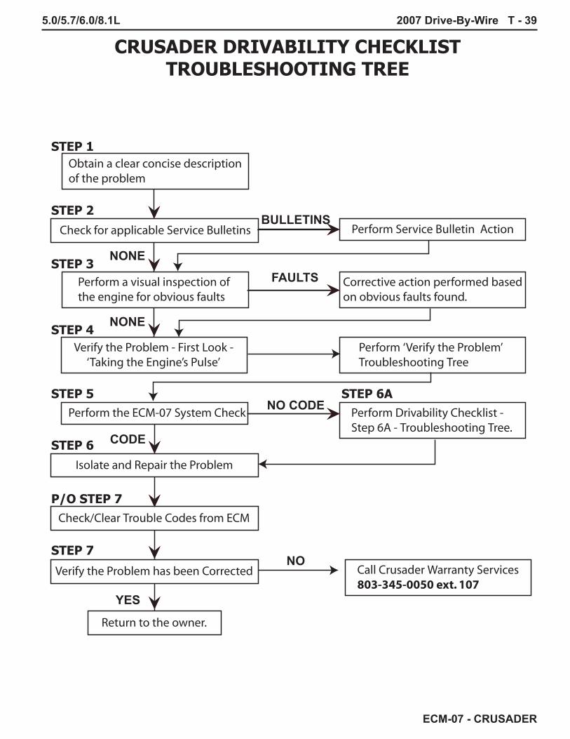
CRUSADER DRIVABILITY CHECKLISTTROUBLESHOOTING TREE
BULLETINS
NONE
FAULTS
NONE
CODE
NO CODE
STEP 1
STEP 2
STEP 3
STEP 4
STEP 5
STEP 6
STEP 6A
P/O STEP 7
STEP 7
YES
NO

T - 40 2007 Drive-By-Wire 5.0/5.7/6.0/8.1L
ECM-07 - CRUSADER
STEP 4
- VERIFY THE PROBLEM -TAKING THE ENGINES PULSE
WATER TEST
STEP 5 - ECM-07 SYSTEM CHECK
YES
YES
NO
NO
VERIFIED
NO

5.0/5.7/6.0/8.1L 2007 Drive-By-Wire T - 41
ECM-07 - CRUSADER
STEP 5
- ECM-07 SYSTEM CHECK -
STEP 6 - ISOLATE AND REPAIR
YESYES
NO
NO
NO
YES
CODESNOCODES
NO
NO
YES
YES

T - 42 2007 Drive-By-Wire 5.0/5.7/6.0/8.1L
ECM-07 - CRUSADER
STEP 6ADRIVABILITY CHECKLIST - NO CODES
WATER TEST
Same

5.0/5.7/6.0/8.1L 2007 Drive-By-Wire T - 43
ECM-07 - CRUSADER
Ignition OFF; Key-ON-Engine-OFF
YES
YES
NO
NO
NO STARTTROUBLESHOOTING TREE
Key-ON-Engine-OFF
Ignition “OFF”.Is B+ present on both terminalsof the following fuses?Fuel Pump, 20AECM, 20AVSW, 5AIgnition, 15A
YES
CODES
NO CODES
YES
NO
YESNO
NO
NO
YES
STEP 5 - ECM-07 SYSTEM CHECK
YES
NO

T - 44 2007 Drive-By-Wire 5.0/5.7/6.0/8.1L
ECM-07 - CRUSADER
KEY
-ON
-EN
GIN
E-O
FF-
FUEL
PU
MP
(S)
DO
N’T
RU
N -
TR
OU
BLE
SHO
OTI
NG
TR
EE
*
**

5.0/5.7/6.0/8.1L 2007 Drive-By-Wire T - 45
ECM-07 - CRUSADER
YEL/RED
GRD
SEN
EXC
BAT
BLACK 6 ga
RED
STARTERBAT
S
I
ALTERNATOR
TRANSMISSIONNEUTRALSAFETYSWITCH
To - EXCAlternator(pin C)
STARTERRelay
To - Elec. Fuel Pumps
BATTERY
+-
IGNITIONRelay
30 86
8587A 87
Not Used
FUELPUMPRelay
To - STBDGRD STUDBELLHOUSING
STARBOARDGROUND STUDBELLHOUSING(BATTERY AND ACCESSORYGROUNDS ONLY)
C
D100 A
To - STBDGRD STUDBELLHOUSING
FROM - ECMFUEL PUMPRELAY CONTROLJ1-84
To - IGNITIONCOIL(S)/MODULE
To - FUELINJECTORS
30 86
8587A 87
Not Used
30 86
8587A 87
Not Used
IgnitionFrom Pin-5
PPL
PNK/DK GRN
BLKGROUND -
ENGINE BLOCK
1 2Low PressureFuel Pump
FuelControlCellB A
To - PORTGRD STUDBELLHOUSING
1Battery
2Ground
2-PINENGINE
HARNESS
8-PINENGINE
HARNESS
7Starter
5Ignition
8
OilPressure
2TACH
3
CoolantTemperature
4Buzzer
6
MalfunctionIndicator
Lamp (MIL)
100A
LITTLE
FUSE 100A
LITTLE
FUSE
PANELFuse 40A
IGNITIONFuse 15A
STARTERFuse 20A
FUEL PUMPFuse 20A
DIAG COMMFuse 15A
ECMFuse 20A
PEG
15
45
75
16
46
76
30
60
9061
31
1
ECM
VSWFuse 5A
J1
FROM -ECM J1-88
FROM -ECM J1-58
FROM -ECM J1-80
FROM -ECM J1-76
FROM -ECM J1-87
RED/PPL
YEL/RED
RED/PPL
TO - ECMIGNITION FEEDJ1-45
FROM - ECMIGNITIONRELAY CONTROLJ1-71
WHT/LT BLU
RED/PPL
LT BLU/WHT
PNK/YEL
TO - ECMBATTERYFEEDJ1-60, J1-79
TO -DLC PIN-ECNC PIN-A
To - ECMJ1-69 / 81
PORTGROUND STUDBELLHOUSING(ENGINE HARNESS GROUNDS ONLY)
1 2
1
2
1 2
1 2
1 2
1 2
1 2
A
B
70 A
FUEL PUMPS POWER / GROUND / CONTROL DIAGRAM

T - 46 2007 Drive-By-Wire 5.0/5.7/6.0/8.1L
ECM-07 - CRUSADER
KEY-ON-ENGINE-OFFFUEL PRESSURE OUT OF RANGE - PUMPS RUN

5.0/5.7/6.0/8.1L 2007 Drive-By-Wire T - 47
ECM-07 - CRUSADER
MAIN ELECTRICAL SYSTEMTROUBLESHOOTING TREE
STARTER CIRCUITTROUBLESHOOTING TREE
SLOW CRANKTROUBLESHOOTING TREE
NO CRANKTROUBLESHOOTING TREE
CHARGE CIRCUITTROUBLESHOOTING TREE
SYSTEM POWER CHECKTROUBLESHOOTING TREE

T - 48 2007 Drive-By-Wire 5.0/5.7/6.0/8.1L
ECM-07 - CRUSADER
SYSTEM POWER CHECKTROUBLESHOOTING TREE

5.0/5.7/6.0/8.1L 2007 Drive-By-Wire T - 49
ECM-07 - CRUSADER
YEL/RED
GRD
SEN
EXC
BAT
BLACK 6 ga
RED
STARTERBAT
S
I
ALTERNATOR
TRANSMISSIONNEUTRALSAFETYSWITCH
To - EXCAlternator(pin C)
STARTERRelay
To - Elec. Fuel Pumps
BATTERY
+-
IGNITIONRelay
30 86
8587A 87
Not Used
FUELPUMPRelay
To - STBDGRD STUDBELLHOUSING
STARBOARDGROUND STUDBELLHOUSING(BATTERY AND ACCESSORYGROUNDS ONLY)
C
D100 A
To - STBDGRD STUDBELLHOUSING
FROM - ECMFUEL PUMPRELAY CONTROLJ1-84
To - IGNITIONCOIL(S)/MODULE
To - FUELINJECTORS
30 86
8587A 87
Not Used
30 86
8587A 87
Not Used
IgnitionFrom Pin-5
PPL
PNK/DK GRN
BLKGROUND -
ENGINE BLOCK
1 2Low PressureFuel Pump
FuelControlCellB A
To - PORTGRD STUDBELLHOUSING
ECM operation is dependant upon maintaining proper ground locations. The port ground stud is for ECM / Engine Harnessgrounds only. Battery ground and all accessory grounds should be located at thestarboard ground stud.
1Battery
2Ground
2-PINENGINE
HARNESS
8-PINENGINE
HARNESS
7Starter
5Ignition
8
OilPressure
2TACH
3
CoolantTemperature
4Buzzer
6
MalfunctionIndicator
Lamp (MIL)
100A
LITTLE
FUSE 100A
LITTLE
FUSE
PANELFuse 40A
IGNITIONFuse 15A
STARTERFuse 20A
FUEL PUMPFuse 20A
DIAG COMMFuse 15A
ECMFuse 20A
PEG
15
45
75
16
46
76
30
60
9061
31
1
ECM
VSWFuse 5A
J1
FROM -ECM J1-88
FROM -ECM J1-58
FROM -ECM J1-80
FROM -ECM J1-76
FROM -ECM J1-87
RED/PPL
YEL/RED
RED/PPL
TO - ECMIGNITION FEEDJ1-45
FROM - ECMIGNITIONRELAY CONTROLJ1-71
WHT/LT BLU
RED/PPL
LT BLU/WHT
PNK/YEL
TO - ECMBATTERYFEEDJ1-60, J1-79
TO -DLC PIN-ECNC PIN-A
To - ECMJ1-69 / 81
PORTGROUND STUDBELLHOUSING(ENGINE HARNESS GROUNDS ONLY)
A
B
70 A
SYSTEM POWER GROUND CIRCUIT DIAGRAM

T - 50 2007 Drive-By-Wire 5.0/5.7/6.0/8.1L
ECM-07 - CRUSADER
SYSTEM POWER KOEO VOLTAGE CHECK CIRCUIT DIAGRAM
YEL/RED
GRD
SEN
EXC
BAT
BLACK 6 ga
RED
STARTERBAT
S
I
ALTERNATOR
TRANSMISSIONNEUTRALSAFETYSWITCH
To - EXCAlternator(pin C)
STARTERRelay
To - Elec. Fuel Pumps
BATTERY
+-
IGNITIONRelay
30 86
8587A 87
Not Used
FUELPUMPRelay
To - STBDGRD STUDBELLHOUSING
STARBOARDGROUND STUDBELLHOUSING(BATTERY AND ACCESSORYGROUNDS ONLY)
C
D100 A
To - STBDGRD STUDBELLHOUSING
FROM - ECMFUEL PUMPRELAY CONTROLJ1-84
To - IGNITIONCOIL(S)/MODULE
To - FUELINJECTORS
30 86
8587A 87
Not Used
30 86
8587A 87
Not Used
IgnitionFrom Pin-5
PPL
PNK/DK GRN
BLKGROUND -
ENGINE BLOCK
1 2Low PressureFuel Pump
FuelControlCellB A
To - PORTGRD STUDBELLHOUSING
1Battery
2Ground
2-PINENGINE
HARNESS
8-PINENGINE
HARNESS
7Starter
5Ignition
8
OilPressure
2TACH
3
CoolantTemperature
4Buzzer
6
MalfunctionIndicator
Lamp (MIL)
100A
LITTLE
FUSE 100A
LITTLE
FUSE
PANELFuse 40A
IGNITIONFuse 15A
STARTERFuse 20A
FUEL PUMPFuse 20A
DIAG COMMFuse 15A
ECMFuse 20A
PEG
15
45
75
16
46
76
30
60
9061
31
1
ECM
VSWFuse 5A
J1
FROM -ECM J1-88
FROM -ECM J1-58
FROM -ECM J1-80
FROM -ECM J1-76
FROM -ECM J1-87
RED/PPL
YEL/RED
RED/PPL
TO - ECMIGNITION FEEDJ1-45
FROM - ECMIGNITIONRELAY CONTROLJ1-71
WHT/LT BLU
RED/PPL
LT BLU/WHT
PNK/YEL
TO - ECMBATTERYFEEDJ1-60, J1-79
TO -DLC PIN-ECNC PIN-A
To - ECMJ1-69 / 81
PORTGROUND STUDBELLHOUSING(ENGINE HARNESS GROUNDS ONLY)
TP-11
TP-12
TP-1
TP-2
TP-8
TP-9
TP-10
TP-7
TP-6
TP-5
TP-4
TP-31 2
1
2
1 2
1 2
1 2
1 2
1 2
With the Key ‘ON’ and boat’snav and panel lights ON, all testpoints should read within .3 vdcof the battery voltage.
A
B
70 A

5.0/5.7/6.0/8.1L 2007 Drive-By-Wire T - 51
ECM-07 - CRUSADER
STARTER CIRCUITTROUBLESHOOTING TREE
From Step 3 of the PCM Drivability Checklist
IMPORTANT: Be sure to Disablethe Diacom Compression Testfeature after performing acompression test or disabling fueland spark.

T - 52 2007 Drive-By-Wire 5.0/5.7/6.0/8.1L
ECM-07 - CRUSADER
YEL/RED
GRD
SEN
EXC
BAT
BLACK 6 ga
RED
STARTERBAT
S
I
ALTERNATOR
TRANSMISSIONNEUTRALSAFETYSWITCH
To - EXCAlternator(pin C)
STARTERRelay
To - Elec. Fuel Pumps
BATTERY
+-
IGNITIONRelay
30 86
8587A 87
Not Used
FUELPUMPRelay
To - STBDGRD STUDBELLHOUSING
STARBOARDGROUND STUDBELLHOUSING(BATTERY AND ACCESSORYGROUNDS ONLY)
C
D100 A
To - STBDGRD STUDBELLHOUSING
FROM - ECMFUEL PUMPRELAY CONTROLJ1-84
To - IGNITIONCOIL(S)/MODULE
To - FUELINJECTORS
30 86
8587A 87
Not Used
30 86
8587A 87
Not Used
IgnitionFrom Pin-5
PPL
PNK/DK GRN
BLKGROUND -
ENGINE BLOCK
1 2Low PressureFuel Pump
FuelControlCellB A
To - PORTGRD STUDBELLHOUSING
1Battery
2Ground
2-PINENGINE
HARNESS
8-PINENGINE
HARNESS
7Starter
5Ignition
8
OilPressure
2TACH
3
CoolantTemperature
4Buzzer
6
MalfunctionIndicator
Lamp (MIL)
100A
LITTLE
FUSE 100A
LITTLE
FUSE
PANELFuse 40A
IGNITIONFuse 15A
STARTERFuse 20A
FUEL PUMPFuse 20A
DIAG COMMFuse 15A
ECMFuse 20A
PEG
15
45
75
16
46
76
30
60
9061
31
1
ECM
VSWFuse 5A
J1
FROM -ECM J1-88
FROM -ECM J1-58
FROM -ECM J1-80
FROM -ECM J1-76
FROM -ECM J1-87
RED/PPL
YEL/RED
RED/PPL
TO - ECMIGNITION FEEDJ1-45
FROM - ECMIGNITIONRELAY CONTROLJ1-71
WHT/LT BLU
RED/PPL
LT BLU/WHT
PNK/YEL
TO - ECMBATTERYFEEDJ1-60, J1-79
TO -DLC PIN-ECNC PIN-A
To - ECMJ1-69 / 81
PORTGROUND STUDBELLHOUSING(ENGINE HARNESS GROUNDS ONLY)
TP-1
TP-2
TP-8
TP-9
TP-7
TP-6
TP-5
TP-4
TP-3
1 2
1
2
1 2
1 2
1 2
1 2
1 2
A
B
70 A
STARTER CIRCUIT DIAGRAM

5.0/5.7/6.0/8.1L 2007 Drive-By-Wire T - 53
ECM-07 - CRUSADER
STARTER CIRCUITTROUBLESHOOTING TREESLOW CRANK CONDITION
****** IMPORTANT ******When you have completed your troubleshooting and repair of the starter,
be sure to disable the Diacom Compression Test feature, then verify the engine starts and runs.

T - 54 2007 Drive-By-Wire 5.0/5.7/6.0/8.1L
ECM-07 - CRUSADER
STARTER CIRCUITTROUBLESHOOTING TREE
NO CRANK CONDITION
****** IMPORTANT ******When you have completed your troubleshooting and repair of the starter, be sure
to disable Diacom Compression Test feature, then verify the engine starts and runs.

5.0/5.7/6.0/8.1L 2007 Drive-By-Wire T - 55
ECM-07 - CRUSADER
CHARGE CIRCUIT DIAGRAM
YEL/RED
GRD
SEN
EXC
BAT
BLACK 6 ga
RED
STARTERBAT
S
I
ALTERNATOR
TRANSMISSIONNEUTRALSAFETYSWITCH
To - EXCAlternator(pin C)
STARTERRelay
To - Elec. Fuel Pumps
BATTERY
+-
IGNITIONRelay
30 86
8587A 87
Not Used
FUELPUMPRelay
To - STBDGRD STUDBELLHOUSING
STARBOARDGROUND STUDBELLHOUSING(BATTERY AND ACCESSORYGROUNDS ONLY)
C
D100 A
To - STBDGRD STUDBELLHOUSING
FROM - ECMFUEL PUMPRELAY CONTROLJ1-84
To - IGNITIONCOIL(S)/MODULE
To - FUELINJECTORS
30 86
8587A 87
Not Used
30 86
8587A 87
Not Used
IgnitionFrom Pin-5
PPL
PNK/DK GRN
BLKGROUND -
ENGINE BLOCK
1 2Low PressureFuel Pump
FuelControlCellB A
To - PORTGRD STUDBELLHOUSING
1Battery
2Ground
2-PINENGINE
HARNESS
8-PINENGINE
HARNESS
7Starter
5Ignition
8
OilPressure
2TACH
3
CoolantTemperature
4Buzzer
6
MalfunctionIndicator
Lamp (MIL)
100A
LITTLE
FUSE 100A
LITTLE
FUSE
PANELFuse 40A
IGNITIONFuse 15A
STARTERFuse 20A
FUEL PUMPFuse 20A
DIAG COMMFuse 15A
ECMFuse 20A
PEG
15
45
75
16
46
76
30
60
9061
31
1
ECM
VSWFuse 5A
J1
FROM -ECM J1-88
FROM -ECM J1-58
FROM -ECM J1-80
FROM -ECM J1-76
FROM -ECM J1-87
RED/PPL
YEL/RED
RED/PPL
TO - ECMIGNITION FEEDJ1-45
FROM - ECMIGNITIONRELAY CONTROLJ1-71
WHT/LT BLU
RED/PPL
LT BLU/WHT
PNK/YEL
TO - ECMBATTERYFEEDJ1-60, J1-79
TO -DLC PIN-ECNC PIN-A
To - ECMJ1-69 / 81
PORTGROUND STUDBELLHOUSING(ENGINE HARNESS GROUNDS ONLY)
1 2
1
2
1 2
1 2
1 2
1 2
1 2
A
B
70 A

T - 56 2007 Drive-By-Wire 5.0/5.7/6.0/8.1L
ECM-07 - CRUSADER
CH
AR
GE
CIR
CU
ITTR
OU
BLE
SHO
OTI
NG
TR
EE

5.0/5.7/6.0/8.1L 2007 Drive-By-Wire T - 57
ECM-07 - CRUSADER
IMPO
RTA
NT:
EC
M-0
7 pr
ovid
es s
igna
l inf
orm
atio
n fo
r ins
trum
ent d
ispl
ays.
A
calib
ratio
n fo
r a d
iffer
ent
inst
rum
ent c
onfig
urat
ion
or
use
of in
stru
men
ts n
ot
supp
orte
d by
EC
M-0
7 m
ay
caus
e er
rone
ous
pane
lre
adin
gs.
Ens
ure
no
prev
ious
wor
k ha
s be
en
perfo
rmed
on
the
EC
M o
r in
stru
men
t pan
el b
efor
e tro
uble
shoo
ting
furth
er.

T - 58 2007 Drive-By-Wire 5.0/5.7/6.0/8.1L
ECM-07 - CRUSADER
The raw water pump volume test must be accomplished with the boat in the water.
Use a container that will hold at least 5 gallons of water.1. Disconnect the hose connected to the output of the Raw Water Pump. Connect a hose of sufficient length to reach the 5 gallon (minimum) container.2. With the boat in the water, not on a trailer. Start the engine and bring the engine RPM up to 4000. Place the hose into the 5 gallon (minimum) container. Hold 4000 RPM for 15 seconds then slowly return to idle and shut off the engine.3. At the 15 seconds point in the test, verify you have at least 5 gallons of water in the container.

5.0/5.7/6.0/8.1L 2007 Drive-By-Wire T - 59
ECM-07 - CRUSADER

T - 60 2007 Drive-By-Wire 5.0/5.7/6.0/8.1L
ECM-07 - CRUSADER
From Step 5 of the PCM Drivability Checklist
IMPORTANT: ECM-07 provides signal information for instrumentdisplays. A calibration for a different instrument configuration or useof instruments not supported by ECM-07 may cause erroneous panelreadings. Ensure no previous work has been performed on the ECM or instrument panel before troubleshooting further.

5.0/5.7/6.0/8.1L 2007 Drive-By-Wire T - 61
ECM-07 - CRUSADER
5.0/5.7L FRESH WATER COOLED WATER FLOW DIAGRAM
W/ R
ISER
W/O
RIS
ER
= R
AWW
ATER
FLO
W
= FR
ESH
WAT
ER F
LOW
1
2
IMPO
RTA
NT:
Acc
esso
ry (i
.e.
heat
er, h
ot w
ater
tank
) Hoo
k U
p
Loca
tion
1 -
Wat
er O
UT
to
heat
er o
r hot
wat
er ta
nk.
Loca
tion
2 -
Wat
er R
ETU
RN
fro
m h
eate
r or h
ot w
ater
tank
. Fi
tting
at b
otto
m o
f hea
t ex
chan
ger O
R c
irc. p
ump.
1
Rem
ove
Hos
es fr
om
raw
wat
er p
ump
and
drai
n ho
ses
com
plet
ely
4
3
= 7
Dra
in L
ocat
ions
5
6
Dra
in P
lugs
@Fr
ont a
nd R
ear
of E
lbow
Dra
in P
lugs
@Fr
ont a
nd R
ear
of E
lbow
7
2
Ret
urnl
ess
Fuel
Sys
temIN
OU
T
TRA
NS.
2

T - 62 2007 Drive-By-Wire 5.0/5.7/6.0/8.1L
ECM-07 - CRUSADER
6.0L RAW WATER COOLED WATER FLOW DIAGRAM
= RAW WATER FLOW
NOTE: Location is the location in order to hook up a hot water accessory.
IMPORTANT: Accessory (i.e. heater, hot water tank) Hook Up
= FRESH WATER FLOW
A
A
= 5 Drain Locations
3
4
2
1
Pressure
Return
Remove Hoses from raw water pump and drain hoses completely
Returnless Fuel System
IN
OUT
OIL
TRANS.
5

5.0/5.7/6.0/8.1L 2007 Drive-By-Wire T - 63
ECM-07 - CRUSADER
21
To E
ngin
eB
lock
To E
ngin
eB
lock
From
Cyl
inde
rH
ead
From
Cyl
inde
rH
ead
= R
AW W
ATER
FLO
W
= FR
ESH
WAT
ER F
LOW
IMPO
RTA
NT:
Acc
esso
ry (i
.e.
heat
er, h
ot w
ater
tank
) Hoo
k U
p
Loca
tion
1 -
Wat
er O
UT
to
heat
er o
r hot
wat
er ta
nk. F
ittin
g at
en
d of
cro
ssov
er.
Loca
tion
2 -
Wat
er R
ETU
RN
fro
m h
eate
r or h
ot w
ater
tank
. Fi
tting
at b
otto
m o
f hea
t ex
chan
ger.
= 7
Dra
in L
ocat
ions
1
Rem
ove
Hos
es fr
om
raw
wat
er p
ump
and
drai
n ho
ses
com
plet
ely
4
3
2
7
6
Dra
in P
lugs
@Fr
ont a
nd R
ear
of E
lbow
5D
rain
Plu
gs @
Fron
t and
Rea
rof
Elb
ow
Ret
urnl
ess
Fuel
Sys
tem
IN
OU
T
TRA
NS.
8.1L RAW WATER COOLED WATER FLOW DIAGRAM
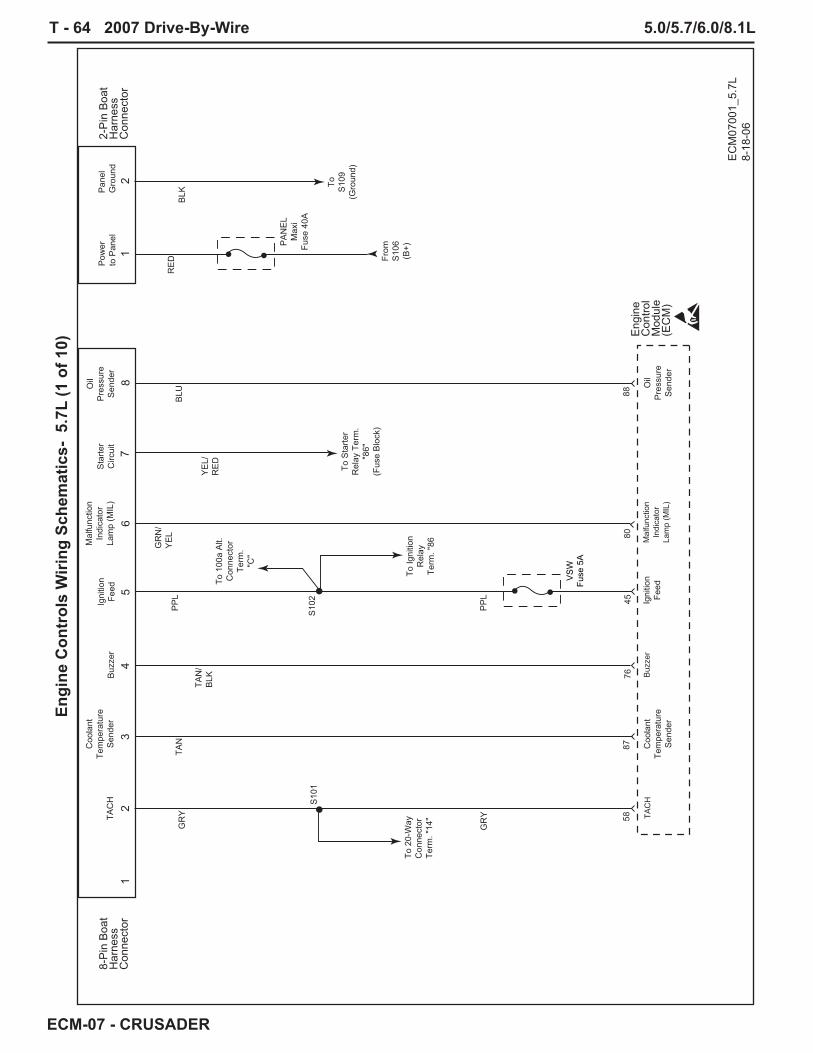
T - 64 2007 Drive-By-Wire 5.0/5.7/6.0/8.1L
ECM-07 - CRUSADER
Engi
ne C
ontr
ols
Wiri
ng S
chem
atic
s- 5
.7L
(1 o
f 10)
8-P
in B
oat
Har
ness
Con
nect
or
2-P
in B
oat
Har
ness
Con
nect
or
EC
M07
001_
5.7L
8-18
-06
Mal
func
tion
Indi
cato
rLa
mp
(MIL
)
80
Buz
zer
76
GR
Y
GR
Y
TAN
TAN
/B
LK
PP
L
PP
L
YE
L/R
ED
GR
N/
YE
L
12
34
56
78
To S10
9(G
roun
d)
Eng
ine
Con
trol
Mod
ule
(EC
M)
45
58
87
BLU 88
To 2
0-W
ayC
onne
ctor
Term
. "14
"
To Ig
nitio
nR
elay
Term
. "86
S10
1S
102
Coo
lant
Tem
pera
ture
Sen
der
Coo
lant
Tem
pera
ture
Sen
der
TAC
HB
uzze
rIg
nitio
nFe
ed
Igni
tion
Feed
Mal
func
tion
Indi
cato
rLa
mp
(MIL
)S
tarte
rC
ircui
t
Oil
Pre
ssur
eS
ende
r
Oil
Pre
ssur
eS
ende
r
PA
NE
LM
axi
Fuse
40A
VS
WFu
se 5
A
To S
tarte
rR
elay
Ter
m.
"86"
(Fus
e B
lock
)
TAC
H
RE
DB
LK
12
From
S10
6(B
+)
Pow
erto
Pan
elP
anel
Gro
und
To 1
00a
Alt.
Con
nect
orTe
rm.
"C"

5.0/5.7/6.0/8.1L 2007 Drive-By-Wire T - 65
ECM-07 - CRUSADER
Engi
ne C
ontr
ols
Wiri
ng S
chem
atic
s- 5
.7L
(2 o
f 10)
EC
M07
002_
5.7L
8-18
-06
RE
D
RE
D
RE
D
RE
D
RE
D/
PP
L
PP
L
PP
L
PP
L
RE
D/
PP
L
BLK
RE
D/
PP
L
Eng
ine
Con
trol
Mod
ule
(EC
M)
Alte
rnat
or
2-W
ayB
oat
Har
ness
Con
nect
or
21
S10
6
S10
3
EC
MFu
se 2
0A
PA
NE
LM
axi
Fuse
40A
VS
WFu
se 5
A
STA
RTE
RR
ELA
YM
axi
Fuse
20A
To S
tarte
rR
elay
Term
. "30
"
Bat
tery
Feed
Bat
tery
Feed
Igni
tion
Feed
6079
45
B+
Sta
rter
Sol
enoi
d 100
amp
fuse
100
amp
fuse
RE
DR
ED
/P
PL
IGN
ITIO
NR
ELA
YFu
se 1
5A
To Ig
nitio
nR
elay
Term
. "30
"
To 1
00a
Alt.
Con
nect
orTe
rm. "
D"
To S10
9(G
roun
d)
From
8-W
ay B
oat
Har
ness
Con
nect
orTe
rm."5
"(Ig
nitio
n)
S10
4
RE
DR
ED
/P
PL
FUE
L P
UM
PR
ELA
YFu
se 2
0A
To F
uel P
ump
Rel
ayTe
rm. "
30" To
100
a A
lt.C
onne
ctor
Term
. "C
"
To Ig
nitio
nR
elay
Term
. "86
"
To F
uel P
ump
Rel
ayTe
rm. "
86"
S10
5
S10
7
S10
2
RE
DR
ED
/P
PL
DIA
GN
OS
TIC
CO
NN
EC
TOR
Fuse
15A
To D
iagn
ostic
Con
nect
orTe
rm. "
E"
To C
AN
Net
wor
kC
onne
ctor
Term
. "A
"

T - 66 2007 Drive-By-Wire 5.0/5.7/6.0/8.1L
ECM-07 - CRUSADER
Engi
ne C
ontr
ols
Wiri
ng S
chem
atic
s- 5
.7L
(3 o
f 10)
EC
M07
003_
5.7L
8-
18-0
6
Eng
ine
Con
trol
Mod
ule
(EC
M)
Pad
dlew
heel
(-)
EC
MG
roun
dE
CM
Gro
und
Kno
ck 2
(-)
Kno
ck 1
(+)
8169
3028
26
Tran
smis
sion
Tem
p.S
witc
h
Tran
smis
sion
Tem
p.S
witc
h
54
BLK
BLK
BLK
PP
L\W
HT
BLK
BLK
BLK
BLK BLK
BLK
BLK
BLK
BLK
BLK
BLK
Ground Stud
BLK
BLK
BLK
S10
9
S10
8
S12
6
S11
0
To 2
0-W
ayC
onne
ctor
Term
. "13
"To
Fue
l Tan
kS
olen
oid
Con
n.Te
rm. "
B"
To C
AN
Net
wor
kC
onne
ctor
Term
. "B
" To D
iagn
ostic
Con
nect
orTe
rm. "
F"
To Ig
nitio
n M
odul
eC
onne
ctor
Term
. "C
"
To 2
0-W
ayC
onne
ctor
Term
. "7"
To 2
-Way
Boa
tH
arne
ssC
onne
ctor
Term
. "2"
To N
eutra
lS
afet
yS
witc
h
To T
CP
Sen
sor
Con
nect
orTe
rm. "
7"To
FC
CC
onne
ctor
Term
. "B
"
To L
.P.
Fuel
Pum
pC
onne
ctor
Term
. "2"
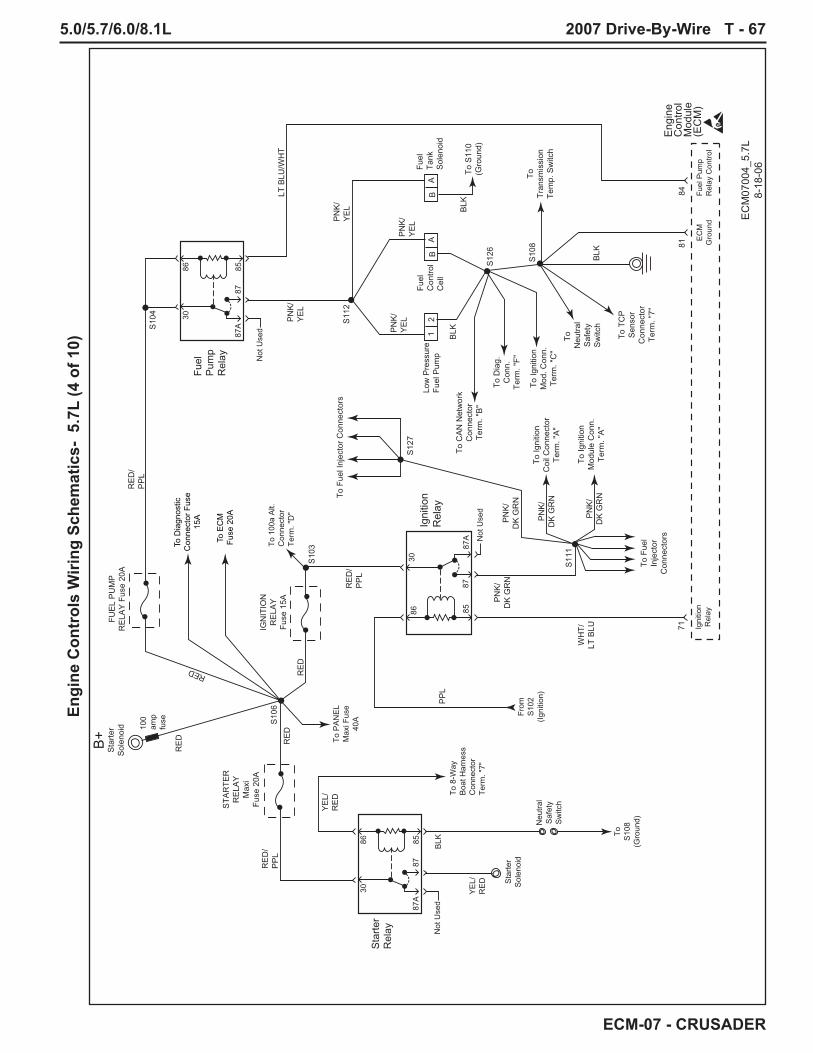
5.0/5.7/6.0/8.1L 2007 Drive-By-Wire T - 67
ECM-07 - CRUSADER
Engi
ne C
ontr
ols
Wiri
ng S
chem
atic
s- 5
.7L
(4 o
f 10)
Eng
ine
Con
trol
Mod
ule
(EC
M)
7184
81
Igni
tion
Rel
ayFu
el P
ump
Rel
ay C
ontro
lE
CM
Gro
und
12
Low
Pre
ssur
eFu
el P
ump
Fuel
Con
trol
Cel
l
Fuel
Tank
Sol
enoi
d
Igni
tion
Rel
ay
EC
M07
004_
5.7L
8-18
-06
BA
BA To
Tran
smis
sion
Tem
p. S
witc
h
To S
110
(Gro
und)
To Ig
nitio
nC
oil C
onne
ctor
Term
. "A
"
To F
uel I
njec
tor C
onne
ctor
s
To F
uel
Inje
ctor
Con
nect
ors
To Ig
nitio
nM
odul
e C
onn.
Term
. "A
"
To T
CP
Sen
sor
Con
nect
orTe
rm. "
7"
To
Neu
tral
Saf
ety
Sw
itch
To C
AN
Net
wor
kC
onne
ctor
Term
. "B
"
To D
iag.
Con
n.Te
rm. "
F"
To Ig
nitio
nM
od. C
onn.
Term
. "C
"
To D
iagn
ostic
Con
nect
or F
use
15A
To E
CM
Fuse
20A
To 8
-Way
Boa
t Har
ness
Con
nect
orTe
rm. "
7"
To P
AN
EL
Max
i Fus
e40
A
To 1
00a
Alt.
Con
nect
orTe
rm. "
D"
From
S10
2(Ig
nitio
n)
To S10
8(G
roun
d)
Sta
rter
Sol
enoi
d
Neu
tral
Saf
ety
Sw
itch
YE
L/R
ED
Sta
rter
Rel
ay
BLK
Not
Use
d
Not
Use
d
30
30
86
8685
85
87A
87A
87
87
Fuel
Pum
pR
elay N
ot U
sed
3086 85
87A
87
RE
D
RE
D/
PP
L
RE
D/
PP
L
PN
K/
YE
L
PN
K/
YE
L
LT B
LU/W
HT
PN
K/
YE
L
PN
K/
YE
L
PP
LB
LK
BLK
BLK
S10
6
S10
4
S11
1
S10
3
S11
2
S10
8
S12
7
S12
6
B+
Sta
rter
Sol
enoi
d 100
amp
fuse
RE
D
RE
D
RED
RE
D/
PP
L
WH
T/LT
BLU
PN
K/
DK
GR
N
PN
K/
DK
GR
N
PN
K/
DK
GR
N
PN
K/
DK
GR
N
YE
L/R
ED
STA
RTE
RR
ELA
YM
axi
Fuse
20A
IGN
ITIO
NR
ELA
YFu
se 1
5A
FUE
L P
UM
PR
ELA
Y F
use
20A

T - 68 2007 Drive-By-Wire 5.0/5.7/6.0/8.1L
ECM-07 - CRUSADER
Engi
ne C
ontr
ols
Wiri
ng S
chem
atic
s- 5
.7L
(5 o
f 10)
20-P
in B
oat
Har
ness
Con
nect
or
EC
M07
005_
5.7L
8-18
-06
GR
Y
PN
K
BLK
BLK
YE
L
BLK
/W
HT
WH
TBR
N
LT
BLU
/B
LK
LT GR
NP
NK
/B
LK
BR
N/
PN
K
OR
N
OR
N/
LT B
LU
OR
N/
GR
N
RE
D/
YE
L
GR
Y
12
34
56
78
910
1112
1314
1516
1718
1920
Eng
ine
Con
trol
Mod
ule
(EC
M)
4642
4725
4426
5152
8658
1214
1543
89
S11
3
S10
9
To T
win
Eng
ine
Con
n.Te
rm. "
6"
To T
win
Eng
ine
Con
n.Te
rm. "
5"
To C
AN
TER
M.
Con
n.Te
rm. "
2"
S10
1
To 8
-Way
Boa
tC
onn.
Term
. "2"
To 2
-Way
Boa
tH
arne
ssC
onn.
Term
. "2"
Not
Use
d
To C
AN
Net
wor
kC
onn.
Term
. "C
"
S11
4
Fuel
Leve
l
Pad
dle
Whe
el(+
)
Pad
dle
Whe
el(-
)
RP
M/
MP
HM
ode
Cru
ise
Set
/C
ance
l
Spe
edIn
c/D
ec
Cru
ise
Sta
tus
Lam
p
Spe
edC
ontro
lG
roun
dTA
CH
VG
OV
CA
NB
US
1(+
)
CA
NB
US
1(-
)
Twin
Eng
ine
Syn
c
Syn
cLa
mp/
Ove
rrid
e
TCP
Gai
nS
elec
t
Per
fect
Pas
sR
eque
st
Fuel
Leve
lP
addl
eW
heel
(+)
Kno
ck 1
(-)
RP
M/
MP
HM
ode
Cru
ise
Set
/C
ance
l
Spe
edIn
c/D
ec
Cru
ise
Sta
tus
Lam
p
TAC
HV
GO
VC
AN
BU
S 1
(+)
CA
NB
US
1(-
)
Twin
Eng
ine
Syn
c
Syn
cLa
mp/
Ove
rrid
e
TCP
Gai
nS
elec
t
Per
fect
Pas
sR
eque
st
To C
AN
Net
wor
kC
onn.
Term
. "D
"
Not
Use
dN
otU
sed
Not
Use
d

5.0/5.7/6.0/8.1L 2007 Drive-By-Wire T - 69
ECM-07 - CRUSADER
Engi
ne C
ontr
ols
Wiri
ng S
chem
atic
s- 5
.7L
(6 o
f 10)
Twin
Eng
ine
Har
ness
Con
nect
or
CA
N T
erm
inat
ion
Con
nect
or/C
ap
CA
N N
etw
ork
Con
nect
or
EC
M07
006_
5.7L
8-18
-06
1513
1811
WH
T
WH
T
BLK
/W
HT
BLK
/W
HT
BLK
/W
HT
PN
K/
GR
N
PN
K/
GR
N
BLK
/W
HT
BLK
/W
HT
BLK
/W
HT
BLK
/WH
T
WH
T
WH
T/O
RN
BLK
/W
HT
LT G
RN
/R
ED
WH
T
BLK
/W
HT
OR
N/
WH
T
GR
N/
YE
L
OR
N/
YE
L
12
34
56
Eng
ine
Con
trol
Mod
ule
(EC
M)
5556
1416
17
To 2
0-W
ayC
onne
ctor
Term
. "16
"
To S
126
(Gro
und)
To S
126
(Gro
und)
To S
119
(Sen
sor
Gro
und)
To S
105
(BA
T)
To S
105
(BA
T)
To S
118
(5 v
olt)
S11
5
S11
3
To 2
0-W
ayC
onne
ctor
Term
. "17
"
S11
4
CA
NB
US
2(-
)
CA
NB
US
1(-
)
CA
N 1
Term
.C
AN
2Te
rm.
Ser
ial
TxS
eria
lR
xM
aste
r/S
lave
CA
NB
US
2(+
)
CA
NB
US
1(+
)
CA
NB
US
2(-
)
CA
NB
US
1(-
)M
aste
r/S
lave
CA
NB
US
2(+
)
CA
NB
US
1(+
)
1 2 3 4D
iagn
ostic
Con
nect
or
A
AB
CD
EF
B C D E F 1 2 3 4
Twis
ted
Twis
ted

T - 70 2007 Drive-By-Wire 5.0/5.7/6.0/8.1L
ECM-07 - CRUSADER
Engi
ne C
ontr
ols
Wiri
ng S
chem
atic
s- 5
.7L
(7 o
f 10)
B
Fuel
Inje
ctor
Driv
er 4
Fuel
Inje
ctor
Driv
er 1
Fuel
Inje
ctor
Driv
er 6
Fuel
Inje
ctor
Driv
er 7
Fuel
Inje
ctor
Driv
er 5
Fuel
Inje
ctor
Driv
er 3
Fuel
Inje
ctor
Driv
er 8
Fuel
Inje
ctor
Driv
er 2
Eng
ine
Con
trol
Mod
ule
(EC
M)
PN
K/
DK
GR
N
PN
K/
D
K
GR
N
PN
K/
D
K
GR
N
PN
K/
D
K
GR
N
PN
K/
D
K
GR
N
PN
K/
DK
GR
N
PN
K/
D
K
G
RN
PN
K/
D
K
G
RN
PN
K/
D
K
GR
N
TAN
/LT
BLU
TAN
/Y
EL
TAN
/B
RN
TAN
/G
RN
GR
Y/
OR
NG
RY
/W
HT
GR
Y/
YE
LG
RY
/B
LU
A
64
Fuel
Inje
ctor
Cyl
inde
r #1
B A
Fuel
Inje
ctor
Cyl
inde
r #3
B A
Fuel
Inje
ctor
Cyl
inde
r #5
B A
Fuel
Inje
ctor
Cyl
inde
r #7
6667
61
A
65
Fuel
Inje
ctor
Cyl
inde
r #2
BB
A
Fuel
Inje
ctor
Cyl
inde
r #4
B A
Fuel
Inje
ctor
Cyl
inde
r #6
B A
Fuel
Inje
ctor
Cyl
inde
r #8
6263
68
S11
1 S12
7
EC
M07
007_
5.7L
8-21
-06
To Ig
nitio
n C
oil
Con
nect
or
Term
. "A
"
To Ig
nitio
n M
odul
eC
onne
ctor
Te
rm. "
A"
From
Igni
tion
Rel
ay T
erm
. "87

5.0/5.7/6.0/8.1L 2007 Drive-By-Wire T - 71
ECM-07 - CRUSADER
Engi
ne C
ontr
ols
Wiri
ng S
chem
atic
s- 5
.7L
(8 o
f 10)
7
4019
2022
2441
Eng
ine
Coo
lant
Tem
pera
ture
(EC
T) S
enso
r
Eng
ine
Con
trol
Mod
ule
(EC
M)
Map
Sen
sor
Sig
nal
Cra
nkS
enso
r(-
)
Sen
sor
Gro
und
CA
MS
enso
r(-
)
Exh
aust
Gas
Tem
p.S
witc
h
Oil
Pre
ssur
eS
enso
rS
igna
l
EC
TS
enso
rS
igna
l
IAT
Sen
sor
Sig
nal
Eng
ine
Con
trol
Mod
ule
(EC
M)
39
A B
S11
8
S11
9
S12
0
S13
0S
129
S28
EC
M07
008_
5.7L
9-1-
06
LT G
RN
/R
ED
LT G
RN
/R
ED
TAN
/W
HT
TAN
/W
HT
YE
L/G
RY
YE
L/G
RY
LT G
RN
/R
ED
LT G
RN
/R
ED
LT G
RN
/R
ED
BLK
/W
HT
BLK/
WHT
BLK/W
HT
BLK
/W
HT
BLK
/W
HT
BLK/
WH
T
BLK
/W
HT
LT G
RN
/R
ED
5 V
olt
Ref
eren
ce
53
Exh
aust
Tem
p.S
witc
h(s
tbd)
Exh
aust
Tem
p.S
witc
h(p
ort)
Oil
Pre
ssur
eS
enso
r
C
AB
To T
hrot
tle
Bod
y C
onn.
Term
. "B
"
To T
hrot
tle B
ody
Con
n. T
erm
. "E
"
To T
CP
Sen
sor
Con
n. T
erm
. "1"
To T
hrot
tle B
ody
Con
n. T
erm
. "D
"
To D
iagn
ostic
Con
n. T
erm
. "A
"
To T
hrot
tle
Bod
y C
onn.
Term
. "H
"To
CA
M S
enso
rC
onn.
Ter
m. "
A"
Kno
ckS
enso
r 1S
igna
l
BLK
/Y
EL
Kno
ckS
enso
r 2S
igna
l
2729
BLK
/W
HT
TAN
/R
ED
LT BLU
LT GR
N
Kno
ckS
enso
r 1(K
S)
Kno
ckS
enso
r 2(K
S)
To T
CP
Sen
sor
Con
n. T
erm
. "6"
To C
rank
Sen
sor C
onn.
Term
. "A
"
To C
AM
Sen
sor C
onn.
Term
. "C
"
To D
iag.
Con
n.Te
rm. "
B"
413
Man
ifold
Abs
olut
eP
ress
ure
(MA
P)/I
ntak
eA
ir Te
mp.
(IAT)
Sen
sor
2
To C
rank
Sen
sor
Con
n. T
erm
. "B
"

T - 72 2007 Drive-By-Wire 5.0/5.7/6.0/8.1L
ECM-07 - CRUSADER
Engi
ne C
ontr
ols
Wiri
ng S
chem
atic
s- 5
.7L
(9 o
f 10)
19
A Th
rottl
e P
ositi
on (T
P) S
enso
r/Act
uato
r(T
hrot
tle B
ody)
Eng
ine
Con
trol
Mod
ule
(EC
M)
Mot
or(+
)M
otor
(-)
RE
F1G
roun
dR
EF1
Gro
und
RE
F1G
roun
dR
EF
2G
roun
d
TPS
enso
r 1S
igna
l
TPS
enso
r 2S
igna
l
5 V
olt
RE
F 1
5 V
olt
RE
F 1
5 V
olt
RE
F 2
5 V
olt
RE
F 1
Mot
or(+
)M
otor
(-)
Sen
sor
Gro
und
TPS
enso
r 1S
igna
l
TPS
enso
r 2S
igna
l
Eng
ine
Con
trol
Mod
ule
(EC
M)
8283
206
5
B
C
D
E
FG
H
EC
M07
009_
5.7L
9-5-
06
5 V
olt
RE
F 1
495 V
olt
RE
F 2
PN
K/
WH
T
LT GR
N/
RE
D
LT GR
N/
PP
L
TAN
/O
RN
BLK
/W
HT
BLK
/W
HT
BLK
/W
HT
LT BLU
/B
LU
PP
L/LT B
LU
LT GR
N/
RE
D
LT GR
N/
RE
D
S11
9
S11
8
Thro
ttle
Con
trol
Pos
ition
(TC
P) S
enso
r/TC
PS
enso
r 2S
igna
l
TCP
Sen
sor 1
Sig
nal
Gro
und
Idle
Val
idat
ion
Sw
itch
TCP
Sen
sor 2
Sig
nal
TCP
Sen
sor 1
Sig
nal
Idle
Val
idat
ion
Sw
itch
RE
F 2
Gro
und
1050
6
3 5
12
OR
N/
BLK
DK
BLU
/O
RN 9
8
PP
L/Y
EL 48
7
BLK
LT GR
N/
BLK
4
To S
108
(Gro
und)

5.0/5.7/6.0/8.1L 2007 Drive-By-Wire T - 73
ECM-07 - CRUSADER
Engi
ne C
ontr
ols
Wiri
ng S
chem
atic
s- 5
.7L
(10
of 1
0)
IC C
ontro
l
Igni
tion
Vol
tage
Igni
tion
Con
trol
Sig
nal
Coi
l Driv
er
Gro
und
Spa
rk P
lugsC
oil
Wire
Igni
tion
Coi
l
Dis
tribu
tor
Igni
tion
Con
trol
Mod
ule
(ICM
)
Hig
h V
olta
geS
witc
h(D
istri
buto
r)
EC
M07
010_
5.7L
9-1-
06
31AA
B
C
D
B
Mou
nted
on
Igni
tion
Coi
lC
YE
L
BLK
PN
KP
NK
YE
L/B
LK
From
S11
1(Ig
nitio
n)
To S12
6(G
roun
d)
From
S11
1(Ig
nitio
n)
Not
Use
d
Cra
nkS
enso
r(+
)
CA
MS
enso
r(+
)
Cra
nkS
enso
r(-
)
CA
MS
enso
r(-
)
5 V
olt
Ref
eren
ce
Cam
shaf
t Pos
ition
(CM
P) S
enso
r
Eng
ine
Con
trol
Mod
ule
(EC
M)
Sol
idS
tate
1924
2221
23
CA
BC
AB
Cra
nksh
aft P
ositi
on (C
KP
) Sen
sor
Sol
idS
tate
EC
MG
roun
d
20
LT G
RN
/R
ED
LT GR
N/
RE
D
WH
T
BLK
/W
HT
BLK
/W
HT
BLK
/W
HT
BLK
/W
HT
WH
T
S11
8
S12
2
S11
9
S12
1
Twis
ted
Twis
ted

T - 74 2007 Drive-By-Wire 5.0/5.7/6.0/8.1L
ECM-07 - CRUSADER
8-P
in B
oat
Har
ness
Con
nect
or
2-P
in B
oat
Har
ness
Con
nect
or
EC
M07
001_
6.0L
8-15
-06
Mal
func
tion
Indi
cato
rLa
mp
(MIL
)
80
Buz
zer
76
GR
Y
GR
Y
TAN
TAN
/B
LK
PP
L
PP
L
YE
L/R
ED
GR
N/
YE
L
12
34
56
78
To S10
9(G
roun
d)
Eng
ine
Con
trol
Mod
ule
(EC
M)
45
58
87
BLU 88
To 2
0-W
ayC
onne
ctor
Term
. "14
"
To 2
0-W
ayC
onne
ctor
Term
. "20
"
To Ig
nitio
nR
elay
Term
. "86
S10
1S
102
Coo
lant
Tem
pera
ture
Sen
der
Coo
lant
Tem
pera
ture
Sen
der
TAC
HB
uzze
rIg
nitio
nFe
ed
Igni
tion
Feed
Mal
func
tion
Indi
cato
rLa
mp
(MIL
)S
tarte
rC
ircui
t
Oil
Pre
ssur
eS
ende
r
Oil
Pre
ssur
eS
ende
r
PA
NE
LM
axi
Fuse
40A
VS
WFu
se 5
A
To S
tarte
rR
elay
Ter
m.
"86"
(Fus
e B
lock
)
TAC
H
RE
DB
LK
12
From
S10
6(B
+)
Pow
erto
Pan
elP
anel
Gro
und
To A
lt.C
onne
ctor
Term
."B
"
Engi
ne C
ontr
ols
Wiri
ng S
chem
atic
s- 6
.0L
(1 o
f 15)

5.0/5.7/6.0/8.1L 2007 Drive-By-Wire T - 75
ECM-07 - CRUSADER
Engi
ne C
ontr
ols
Wiri
ng S
chem
atic
s- 6
.0L
(2 o
f 15)
EC
M07
002_
6.0L
8-15
-06
RE
D
RE
D
RE
D
RE
D
RE
D/
PP
L
PP
L
PP
L
PP
L
PP
L
RE
D/
PP
L
BLK
RE
D/
PP
L
Eng
ine
Con
trol
Mod
ule
(EC
M)
Alte
rnat
or
2-W
ayB
oat
Har
ness
Con
nect
or
21
S10
6
S10
3
EC
MFu
se 2
0A
PA
NE
LM
axi
Fuse
40A
VS
WFu
se 5
A
STA
RTE
RR
ELA
YM
axi
Fuse
20A
To S
tarte
rR
elay
Term
. "30
"
Bat
tery
Feed
Bat
tery
Feed
Igni
tion
Feed
6079
45
B+
Sta
rter
Sol
enoi
d 100
amp
fuse
100
amp
fuse
RE
DR
ED
/P
PL
IGN
ITIO
NR
ELA
YFu
se 1
5A
To Ig
nitio
nR
elay
Term
. "30
"
To A
ltter
nato
rC
onne
ctor
Term
. "A
"
To S10
9(G
roun
d)
From
8-W
ay B
oat
Har
ness
Con
nect
orTe
rm."5
"(Ig
nitio
n)
S10
4
RE
DR
ED
/P
PL
FUE
L P
UM
PR
ELA
YFu
se 2
0A
To F
uel P
ump
Rel
ayTe
rm. "
30" To
Alte
rnat
orC
onne
ctor
Term
. "B
"
To 2
0-W
ayC
onne
ctor
Term
. "20
"
To Ig
nitio
nR
elay
Term
. "86
"
To F
uel P
ump
Rel
ayTe
rm. "
86"
S10
5
S10
7
S10
2
RE
DR
ED
/P
PL
DIA
GN
OS
TIC
CO
NN
EC
TOR
Fuse
15A
To D
iagn
ostic
Con
nect
orTe
rm. "
E"
To C
AN
Net
wor
kC
onne
ctor
Term
. "A
"
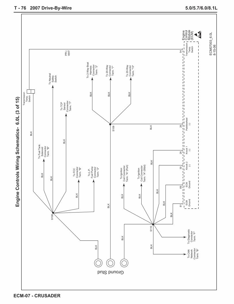
T - 76 2007 Drive-By-Wire 5.0/5.7/6.0/8.1L
ECM-07 - CRUSADER
Engi
ne C
ontr
ols
Wiri
ng S
chem
atic
s- 6
.0L
(3 o
f 15)
EC
M07
003_
6.0L
8-
15-0
6
Eng
ine
Con
trol
Mod
ule
(EC
M)
Pad
dlew
heel
(-)
EC
MG
roun
dE
CM
Gro
und
Kno
ck 2
(-)
Kno
ck 1
(-)
8169
3028
26
Tran
smis
sion
Tem
p.S
witc
h
Tran
smis
sion
Tem
p.S
witc
h
54
BLK
BLK
BLK
PP
L\W
HT
BLK
BLK
BLK
BLK
BLK
BLK
BLK
BLK
BLK
BLK
BLK
BLK
Ground Stud
BLK
BLK
BLK
BLK
S10
9
S10
8
S11
0
To 2
0-W
ayC
onne
ctor
Term
. "13
"
To Ig
nitio
nC
oil C
onne
ctor
Term
. "A
" (P
ort)
To Ig
nitio
nC
oil C
onne
ctor
Term
. "A
" (S
tbd)
To C
AN
Net
wor
kC
onne
ctor
Term
. "B
"
To D
iagn
ostic
Con
nect
orTe
rm. "
F"
To 2
0-W
ayC
onne
ctor
Term
. "7"
To 2
-Way
Boa
tH
arne
ssC
onne
ctor
Term
. "2"
To F
uel T
ank
Sol
enoi
dC
onne
ctor
Term
. "B
"To
Neu
tral
Saf
ety
Sw
itch
To T
CP
Sen
sor
Con
nect
orTe
rm. "
7"To
FC
CC
onne
ctor
Term
. "B
"
To L
.P.
Fuel
Pum
pC
onne
ctor
Term
. "2"

5.0/5.7/6.0/8.1L 2007 Drive-By-Wire T - 77
ECM-07 - CRUSADER
Engi
ne C
ontr
ols
Wiri
ng S
chem
atic
s- 6
.0L
(4 o
f 15)
Eng
ine
Con
trol
Mod
ule
(EC
M)
7184
Igni
tion
Rel
ayFu
el P
ump
Rel
ay C
ontro
l
12
Low
Pre
ssur
eFu
el P
ump
Fuel
Con
trol
Cel
l
Fuel
Tank
Sol
enoi
d
Igni
tion
Rel
ay
EC
M07
004_
6.0L
8-15
-06
BA
BA
To Ig
nitio
nC
oil C
onne
ctor
Term
. "H
" (P
ort)
ToTr
ansm
issi
onTe
mp.
Sw
itch
To Ig
nitio
nC
oil C
onne
ctor
Term
. "H
" (S
tbd)
To F
uel
Inje
ctor
Con
nect
orTe
rm. "
J"
To T
CP
Sen
sor
Con
nect
orTe
rm. "
7"
To
Neu
tral
Saf
ety
Sw
itch
To F
uel
Inje
ctor
Con
nect
orTe
rm. "
K"
To 8
-Way
Boa
t Har
ness
Con
nect
orTe
rm. "
7"
To A
ltern
ator
Con
nect
orTe
rm. "
A"
From
S10
2(Ig
nitio
n)
To S10
8(G
roun
d)
Sta
rter
Sol
enoi
d
Neu
tral
Saf
ety
Sw
itch
YE
L/R
ED
Sta
rter
Rel
ay
BLK
Not
Use
d
Not
Use
d
30
30
86
8685
85
87A
87A
87
87
Fuel
Pum
pR
elay N
ot U
sed
3086 85
87A
87
RE
D
RE
D/
PP
L
RE
D/
PP
L
PN
K/
YE
L
PN
K/
YE
L
LT B
LU/W
HT
PN
K/
YE
L
PN
K/
YE
L
PP
L
BLK
BLK
BLK
S10
6
S10
4
S11
1
S10
3
S11
2
S10
8
B+
Sta
rter
Sol
enoi
d 100
amp
fuse
RE
D
RE
D
RED
RE
D/
PP
L
WH
T/LT
BLU
PN
K/
DK
GR
N
PN
K/
DK
GR
N
YE
L/R
ED
STA
RTE
RR
ELA
YM
axi
Fuse
20A
IGN
ITIO
NR
ELA
YFu
se 1
5A
FUE
L P
UM
PR
ELA
YM
axi
Fuse
20A

T - 78 2007 Drive-By-Wire 5.0/5.7/6.0/8.1L
ECM-07 - CRUSADER
Engi
ne C
ontr
ols
Wiri
ng S
chem
atic
s- 6
.0L
(5 o
f 15)
20-P
in B
oat
Har
ness
Con
nect
or
EC
M07
005_
6.0L
8-18
-06
GR
Y
PN
K
BLK
BLK
YE
L
BLK
/W
HT
WH
TBR
N
LT
BLU
/B
LK
PP
LLT G
RN
PN
K/
BLK
BR
N/
PN
K
OR
N
OR
N/
LT B
LU
OR
N/
GR
N
RE
D/
YE
L
GR
Y
12
34
56
78
910
1112
1314
1516
1718
1920
Eng
ine
Con
trol
Mod
ule
(EC
M)
4642
4725
4426
5152
8658
1214
1543
89
S11
3
S10
9
To T
win
Eng
ine
Con
n.Te
rm. "
6"
To T
win
Eng
ine
Con
n.Te
rm. "
5"
To C
AN
TER
M.
Con
n.Te
rm. "
2"
S10
1
To 8
-Way
Boa
tC
onn.
Term
. "2"
From
S10
2(Ig
nitio
n)
To 2
-Way
Boa
tH
arne
ssC
onn.
Term
. "2"
To C
AN
Net
wor
kC
onn.
Term
. "C
"
S11
4
Fuel
Leve
l
Pad
dle
Whe
el(+
)
Pad
dle
Whe
el(-
)
RP
M/
MP
HM
ode
Cru
ise
Set
/C
ance
l
Spe
edIn
c/D
ec
Cru
ise
Sta
tus
Lam
p
Spe
edC
ontro
lG
roun
dTA
CH
VG
OV
CA
NB
US
1(+
)
CA
NB
US
1(-
)
Twin
Eng
ine
Syn
c
Syn
cLa
mp/
Ove
rrid
e
Spe
edC
ontro
lIg
nitio
n
TCP
Gai
nS
elec
t
Per
fect
Pas
sR
eque
st
Fuel
Leve
lP
addl
eW
heel
(+)
EC
MG
roun
dR
PM
/M
PH
Mod
e
Cru
ise
Set
/C
ance
l
Spe
edIn
c/D
ec
Cru
ise
Sta
tus
Lam
p
TAC
HV
GO
VC
AN
BU
S 1
(+)
CA
NB
US
1(-
)
Twin
Eng
ine
Syn
c
Syn
cLa
mp/
Ove
rrid
e
TCP
Gai
nS
elec
t
Per
fect
Pas
sR
eque
st
To C
AN
Net
wor
kC
onn.
Term
. "D
"

5.0/5.7/6.0/8.1L 2007 Drive-By-Wire T - 79
ECM-07 - CRUSADER
Engi
ne C
ontr
ols
Wiri
ng S
chem
atic
s- 6
.0L
(6 o
f 15)
Twin
Eng
ine
Har
ness
Con
nect
or
CA
N T
erm
inat
ion
Con
nect
or/C
ap
CA
N N
etw
ork
Con
nect
or
EC
M07
006_
6.0L
8-18
-06
1513
1811
WH
T
WH
T
BLK
/W
HT
BLK
/W
HT
BLK
/W
HT
PN
K/
GR
N
PN
K/
GR
N
BLK
/G
RN
BLK
/W
HT
WH
T
WH
T
BLK
/W
HT
LT G
RN
/R
ED
WH
T
BLK
/W
HT
WH
T
GR
N/
YE
L
OR
N/
YE
L
12
34
56
Eng
ine
Con
trol
Mod
ule
(EC
M)
5556
1416
17
To 2
0-W
ayC
onne
ctor
Term
. "16
"
To S
110
(Gro
und)
To S
110
(Gro
und)
To S
119
(Sen
sor
Gro
und)
To S
105
(BA
T)
To S
105
(BA
T)
To S
118
(5 v
olt)
S11
5
S11
3
To 2
0-W
ayC
onne
ctor
Term
. "17
"
S11
4
CA
NB
US
2(-
)
CA
NB
US
1(-
)
CA
N 1
Term
.C
AN
2Te
rm.
Ser
ial
TxS
eria
lR
xM
aste
r/S
lave
CA
NB
US
2(+
)
CA
NB
US
1(+
)
CA
NB
US
2(-
)
CA
NB
US
1(-
)M
aste
r/S
lave
CA
NB
US
2(+
)
CA
NB
US
1(+
)
1 2 3 4D
iagn
ostic
Con
nect
or
A
AB
CD
EF
B C D E F 1 2 3 4
Twis
ted
Twis
ted

T - 80 2007 Drive-By-Wire 5.0/5.7/6.0/8.1L
ECM-07 - CRUSADER
Engi
ne C
ontr
ols
Wiri
ng S
chem
atic
s- 6
.0L
(7 o
f 15)
B
Fuel
Inje
ctor
Driv
er 7
Fuel
Inje
ctor
Driv
er 1
Fuel
Inje
ctor
Driv
er 5
Fuel
Inje
ctor
Driv
er 3
Fuel
Inje
ctor
Driv
er 6
Fuel
Inje
ctor
Driv
er 8
Fuel
Inje
ctor
Driv
er 4
Fuel
Inje
ctor
Driv
er 2
Eng
ine
Con
trol
Mod
ule
(EC
M)
PN
K/
DK
GR
N
PN
K/
D
K
GR
NP
NK
/
DK
G
RN
PN
K/
D
K
GR
N
PN
K/
D
K
GR
N
PN
K/
DK
GR
N
PN
K/
D
K
G
RN
PN
K/
D
K
G
RN
PN
K/
D
K
GR
N
TAN
TAN
TAN
TAN
GR
YG
RY
GR
YG
RY
A
67
Fuel
Inje
ctor
Cyl
inde
r #1
B A
Fuel
Inje
ctor
Cyl
inde
r #4
B A
Fuel
Inje
ctor
Cyl
inde
r #6
B A
Fuel
Inje
ctor
Cyl
inde
r #7
6563
61
A
66
Fuel
Inje
ctor
Cyl
inde
r #2
BB
A
Fuel
Inje
ctor
Cyl
inde
r #3
B A
Fuel
Inje
ctor
Cyl
inde
r #5
B A
Fuel
Inje
ctor
Cyl
inde
r #8
6268
64
S11
1
S11
6S
117
EC
M07
007_
6.0L
8-15
-06
To Ig
nitio
n C
oil
Con
nect
or (o
dd c
yl.)
Term
. "H
"To
Igni
tion
Coi
lC
onne
ctor
(eve
n cy
l.)Te
rm. "
H"
From
Igni
tion
Rel
ay T
erm
. "87
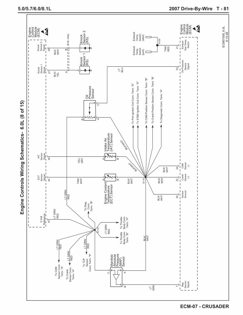
5.0/5.7/6.0/8.1L 2007 Drive-By-Wire T - 81
ECM-07 - CRUSADER
Engi
ne C
ontr
ols
Wiri
ng S
chem
atic
s- 6
.0L
(8 o
f 15)
7
4019
2022
2441
BAC
Man
ifold
Abs
olut
eP
ress
ure
(MA
P)
Sen
sor
Eng
ine
Coo
lant
Tem
pera
ture
(EC
T) S
enso
r
Eng
ine
Con
trol
Mod
ule
(EC
M)
Map
Sen
sor
Sig
nal
Cra
nkS
enso
r(-
)
Sen
sor
Gro
und
CA
MS
enso
r(-
)
Exh
aust
Gas
Tem
p.S
witc
h
Oil
Pre
ssur
eS
enso
rS
igna
l
EC
TS
enso
rS
igna
l
IAT
Sen
sor
Sig
nal
Eng
ine
Con
trol
Mod
ule
(EC
M)
39
A B
Inta
ke A
irTe
mpe
ratu
re(IA
T) S
enso
r
A B
S11
8
S11
9
S12
0
EC
M07
008_
6.0L
8-15
-06
LT G
RN
/R
ED
LT G
RN
/R
ED
TAN
/W
HT
YE
L/G
RY
LT G
RN
/R
ED
LT G
RN
/R
ED
LT G
RN
/R
ED
BLK
/W
HT
BLK/
WHT
BLK/W
HT
BLK
/W
HT
BLK
/W
HT
BLK
/W
HT
BLK
/W
HT
LT G
RN
/R
ED
5 V
olt
Ref
eren
ce
53
Exh
aust
Tem
p.S
witc
h(s
tbd)
Exh
aust
Tem
p.S
witc
h(p
ort)
Oil
Pre
ssur
eS
enso
rC
AB
To P
ort I
gniti
on C
oil C
onn.
Ter
m. "
E"
To T
hrot
tle
Bod
y C
onn.
Term
. "B
"
To T
hrot
tle
Bod
y C
onn.
Term
. "H
"
To S
TBD
Igni
tion
Coi
l Con
n. T
erm
. "E
"
To C
AM
Pos
ition
Sen
sor C
onn.
Ter
m. "
B"
To C
rank
Pos
ition
Sen
sor C
onn.
Ter
m. "
B"
To D
iagn
ostic
Con
n. T
erm
. "A
"
Kno
ckS
enso
r 1S
igna
l
BLK
/Y
EL
(6.0
L on
ly)
Kno
ckS
enso
r 2S
igna
l
2729
BLK
/W
HT TA
N/
RE
D
LT BLU
LT GR
N
Kno
ckS
enso
r 1(K
S)
Kno
ckS
enso
r 2(K
S)
AB
To T
CP
Sen
sor
Con
n. T
erm
. "6"
To C
rank
Sen
sor C
onn.
Term
. "A
"
To C
AM
Sen
sor C
onn.
Term
. "A
"
To D
iag.
Con
n.Te
rm. "
B"

T - 82 2007 Drive-By-Wire 5.0/5.7/6.0/8.1L
ECM-07 - CRUSADER
Engi
ne C
ontr
ols
Wiri
ng S
chem
atic
s- 6
.0L
(9 o
f 15)
19
A Th
rottl
e P
ositi
on (T
P) S
enso
r/Act
uato
r(T
hrot
tle B
ody)
Eng
ine
Con
trol
Mod
ule
(EC
M)
Mot
or(+
)M
otor
(-)
RE
F1G
roun
dR
EF1
Gro
und
RE
F1G
roun
dR
EF
2G
roun
d
TPS
enso
r 1S
igna
l
TPS
enso
r 2S
igna
l
5 V
olt
RE
F 1
5 V
olt
RE
F 1
5 V
olt
RE
F 2
5 V
olt
RE
F 1
Mot
or(+
)M
otor
(-)
Sen
sor
Gro
und
TPS
enso
r 1S
igna
l
TPS
enso
r 2S
igna
l
Eng
ine
Con
trol
Mod
ule
(EC
M)
8283
206
5
B
C
D
E
FG
H
EC
M07
009_
6.0L
8-15
-06
5 V
olt
RE
F 1
495 V
olt
RE
F 2
PN
K/
WH
T
LT GR
N/
RE
D
LT GR
N/
PP
L
TAN
/O
RN
BLK
/W
HT
BLK
/W
HT
BLK
/W
HT
LT BLU
/B
LU
PP
L/LT B
LU
LT GR
N/
RE
D
LT GR
N/
RE
D
S11
9
S11
8
Thro
ttle
Con
trol
Pos
ition
(TC
P) S
enso
r/TC
PS
enso
r 2S
igna
l
TCP
Sen
sor 1
Sig
nal
Gro
und
Idle
Val
idat
ion
Sw
itch
TCP
Sen
sor 2
Sig
nal
TCP
Sen
sor 1
Sig
nal
Idle
Val
idat
ion
Sw
itch
RE
F 2
Gro
und
1050
6
3 5
12
OR
N/
BLK
DK
BLU
/O
RN 9
8
PP
L/Y
EL 48
7
BLK
LT GR
N/
BLK
4
To S
108
(Gro
und)

5.0/5.7/6.0/8.1L 2007 Drive-By-Wire T - 83
ECM-07 - CRUSADER
Engi
ne C
ontr
ols
Wiri
ng S
chem
atic
s- 6
.0L
(10
of 1
5)
ECM07010_6.0L8-2-06
6.0L Engine
CrankSensor
(+)
CAMSensor
(+)
CrankSensor
(-)
CAMSensor
(-)
5 VoltReference
CamshaftPosition(CMP)Sensor
EngineControlModule(ECM)
SolidState
19 242221 23
CC
AA
BB
CrankshaftPosition(CKP)Sensor
SolidState
ECMGround
20
LT GRN/RED
LTGRN/RED
WHT
BLK/WHT
BLK/WHT
BLK/WHT
BLK/WHT
GRY/BRN
S118
S122
S119
S121
Twisted
Twisted

T - 84 2007 Drive-By-Wire 5.0/5.7/6.0/8.1L
ECM-07 - CRUSADER
Engi
ne C
ontr
ols
Wiri
ng S
chem
atic
s- 6
.0L
(11
of 1
5)
38
EC
M G
roun
dIg
nitio
n C
ontro
l AIg
nitio
n C
ontro
l H
Spa
rkP
lug
Spa
rkP
lug
Igni
tion
Coi
l(c
ylin
der #
1)
Firin
g O
rder
:
1 -
8 - 7
- 2
- 6 -
5 - 4
- 3
Igni
tion
Con
trol:
A -
B -
C -
D -
E -
F - G
- H
Igni
tion
Coi
ls(c
ylin
ders
#5
& #
7)
Igni
tion
Coi
ls(c
ylin
ders
#5
& #
7)
Igni
tion
Coi
l(c
ylin
der #
3)Eng
ine
Con
trol
Mod
ule
(EC
M)
BLK
15
1
BLK
15
1 B
LK
151
BR
N
2129
BR
N
2129
BLK
/W
HT
PN
K/
GR
NY
EL/
BLU
LT B
LU 2
123
YE
L
PP
L 2
121
PN
K 3
9P
NK
39
PN
K 3
9P
NK
39
C10
9
S12
4
S11
9
S12
5
S12
3
EC
M07
011_
6.0L
8-15
-06
Igni
tion
Ref
eren
ce
Low
IC S
igna
l
Gro
und
Igni
tion
Ref
eren
ce
Low
IC S
igna
l
Gro
und
2031 A
DD
CGH
E A
F
BB
C A
To S
110
(Gro
und)
To Ig
nitio
n C
oil
Con
nect
or (e
ven
cyl.)
Term
"E"
To S
111
(Igni
tion)
To O
ther
Sen
sor
Gro
unds

5.0/5.7/6.0/8.1L 2007 Drive-By-Wire T - 85
ECM-07 - CRUSADER
Engi
ne C
ontr
ols
Wiri
ng S
chem
atic
s- 6
.0L
(12
of 1
5)
35
EC
M G
roun
dIg
nitio
n C
ontro
l FIg
nitio
n C
ontro
l C
Spa
rkP
lug
Spa
rkP
lug
Igni
tion
Coi
l(c
ylin
der #
5)
Firin
g O
rder
:
1 -
8 - 7
- 2
- 6 -
5 - 4
- 3
Igni
tion
Con
trol:
A -
B -
C -
D -
E -
F - G
- H
Igni
tion
Coi
ls(c
ylin
ders
#1
& #
3)
Igni
tion
Coi
ls(c
ylin
ders
#1
& #
3)
Igni
tion
Coi
l(c
ylin
der #
7)Eng
ine
Con
trol
Mod
ule
(EC
M)
BLK
15
1
BLK
15
1 B
LK
151
BR
N
2129
BR
N
2129
BLK
/W
HT
PN
K/
GR
NY
EL/
WH
T
LT B
LU 2
123
YE
L/G
RN
PP
L 2
121
PN
K 3
9P
NK
39
PN
K 3
9P
NK
39
C10
9
S12
4
S11
9
S12
5
S12
3
EC
M07
012_
6.0L
8-15
-06
Igni
tion
Ref
eren
ce
Low
IC S
igna
l
Gro
und
Igni
tion
Ref
eren
ce
Low
IC S
igna
l
Gro
und
2034 A
DD
CCH
E A
B
BB
C A
To S
110
(Gro
und)
To Ig
nitio
n C
oil
Con
nect
or (e
ven
cyl.)
Term
"E"
To S
111
(Igni
tion)
To O
ther
Sen
sor
Gro
unds

T - 86 2007 Drive-By-Wire 5.0/5.7/6.0/8.1L
ECM-07 - CRUSADER
Engi
ne C
ontr
ols
Wiri
ng S
chem
atic
s- 6
.0L
(13
of 1
5)
36
EC
M G
roun
dIg
nitio
n C
ontro
l DIg
nitio
n C
ontro
l G
Spa
rkP
lug
Spa
rkP
lug
Igni
tion
Coi
l(c
ylin
der #
2)
Firin
g O
rder
:
1 -
8 - 7
- 2
- 6 -
5 - 4
- 3
Igni
tion
Con
trol:
A -
B -
C -
D -
E -
F - G
- H
Igni
tion
Coi
ls(c
ylin
ders
#6
& #
8)
Igni
tion
Coi
ls(c
ylin
ders
#6
& #
8)
Igni
tion
Coi
l(c
ylin
der #
4)Eng
ine
Con
trol
Mod
ule
(EC
M)
BLK
15
1
BLK
15
1 B
LK
151
BR
N
2129
BR
N
2129
BLK
/W
HT
PN
K/
GR
NW
HT/
BLK
LT B
LU 2
123
WH
T/B
RN
PP
L 2
121
PN
K 3
9P
NK
39
PN
K 3
9P
NK
39
C11
0
S12
4
S11
9
S12
5
S12
3
EC
M07
013_
6.0L
8-15
-06
Igni
tion
Ref
eren
ce
Low
IC S
igna
l
Gro
und
Igni
tion
Ref
eren
ce
Low
IC S
igna
l
Gro
und
2037 A
DD
CBH
E A
C
BB
C A
To S
110
(Gro
und)
To Ig
nitio
n C
oil
Con
nect
or (o
dd c
yl.)
Term
"E"
To S
111
(Igni
tion)
To O
ther
Sen
sor
Gro
unds

5.0/5.7/6.0/8.1L 2007 Drive-By-Wire T - 87
ECM-07 - CRUSADER
Engi
ne C
ontr
ols
Wiri
ng S
chem
atic
s- 6
.0L
(14
of 1
5)
33
EC
M G
roun
dIg
nitio
n C
ontro
l EIg
nitio
n C
ontro
l B
Spa
rkP
lug
Spa
rkP
lug
Igni
tion
Coi
l(c
ylin
der #
6)
Firin
g O
rder
:
1 -
8 - 7
- 2
- 6 -
5 - 4
- 3
Igni
tion
Con
trol:
A -
B -
C -
D -
E -
F - G
- H
Igni
tion
Coi
ls(c
ylin
ders
#2
& #
4)
Igni
tion
Coi
ls(c
ylin
ders
#2
& #
4)
Igni
tion
Coi
l(c
ylin
der #
8)Eng
ine
Con
trol
Mod
ule
(EC
M)
BLK
15
1
BLK
15
1 B
LK
151
BR
N
2129
BR
N
2129
BLK
/W
HT
PN
K/
GR
NW
HT/
GR
N
LT B
LU 2
123
WH
T/R
ED
PP
L 2
121
PN
K 3
9P
NK
39
PN
K 3
9P
NK
39
C11
0
S12
4
S11
9
S12
5
S12
3
EC
M07
014_
6.0L
8-15
-06
Igni
tion
Ref
eren
ce
Low
IC S
igna
l
Gro
und
Igni
tion
Ref
eren
ce
Low
IC S
igna
l
Gro
und
2032 A
DD
CFH
E A
G
BB
C A
To S
110
(Gro
und)
To Ig
nitio
n C
oil
Con
nect
or (o
dd c
yl.)
Term
"E"
To S
111
(Igni
tion)
To O
ther
Sen
sor
Gro
unds

T - 88 2007 Drive-By-Wire 5.0/5.7/6.0/8.1L
ECM-07 - CRUSADER
Engi
ne C
ontr
ols
Wiri
ng S
chem
atic
s- 6
.0L
(15
of 1
5)
EC
M07
015_
6.0L
8-15
-06
Igni
tion
Con
trol H
38
Igni
tion
Con
trol A
Cyl
inde
r#1
Cyl
inde
r#3
Cyl
inde
r#5
Cyl
inde
r#7
Cyl
inde
r#2
Cyl
inde
r#4
Cyl
inde
r#6
Cyl
inde
r#8
31
BLK
YE
L/W
HT
YE
L/G
RN
YE
L/B
LUY
EL
PN
K/
GR
N
PN
K/
GR
N
AB
CD
EF
GH
Eng
ine
Con
trol
Mod
ule
(EC
M)
Igni
tion
Con
trol C
35
Igni
tion
Con
trol F
Igni
tion
Con
trol E
Igni
tion
Con
trol B
Igni
tion
Con
trol D
Igni
tion
Con
trol G
34
3233
3736
Not
Use
d
Not
Use
d
Igni
tion
Coi
lC
onne
ctor
(eve
n cy
l.)
Igni
tion
Coi
lC
onne
ctor
(odd
cyl
.)
BLK
WH
T/B
RN
WH
T/ B
LKW
HT/
RE
DW
HT/
GR
N
AB
CD
EF
GH
To S11
0(G
roun
d)
To S11
0(G
roun
d)
S11
1
To O
ther
Sen
sor
Gro
unds
To O
ther
Sen
sor
Gro
unds
EC
M G
roun
d
EC
M G
roun
d
BLK
/W
HT
BLK
/W
HT
S11
9
2020
S11
9
From
Igni
tion
Rel
ayTe
rm. "
87"
To In
ject
ors

5.0/5.7/6.0/8.1L 2007 Drive-By-Wire T - 89
ECM-07 - CRUSADER
Engi
ne C
ontr
ols
Wiri
ng S
chem
atic
s- 8
.1L
(1 o
f 15)
8-P
in B
oat
Har
ness
Con
nect
or
2-P
in B
oat
Har
ness
Con
nect
or
EC
M07
001_
8.1L
8-15
-06
Mal
func
tion
Indi
cato
rLa
mp
(MIL
)
80
Buz
zer
76
GR
Y
GR
Y
TAN
TAN
/B
LK
PP
L
PP
L
YE
L/R
ED
GR
N/
YE
L
12
34
56
78
To S10
9(G
roun
d)
Eng
ine
Con
trol
Mod
ule
(EC
M)
45
58
87
BLU 88
To 2
0-W
ayC
onne
ctor
Term
. "14
"
To 2
0-W
ayC
onne
ctor
Term
. "20
"
To Ig
nitio
nR
elay
Term
. "86
S10
1S
102
Coo
lant
Tem
pera
ture
Sen
der
Coo
lant
Tem
pera
ture
Sen
der
TAC
HB
uzze
rIg
nitio
nFe
ed
Igni
tion
Feed
Mal
func
tion
Indi
cato
rLa
mp
(MIL
)S
tarte
rC
ircui
t
Oil
Pre
ssur
eS
ende
r
Oil
Pre
ssur
eS
ende
r
PA
NE
LM
axi
Fuse
40A
VS
WFu
se 5
A
To S
tarte
rR
elay
Ter
m.
"86"
(Fus
e B
lock
)
TAC
H
RE
DB
LK
12
From
S10
6(B
+)
Pow
erto
Pan
elP
anel
Gro
und
To A
lt.C
onne
ctor
Term
."B
"

T - 90 2007 Drive-By-Wire 5.0/5.7/6.0/8.1L
ECM-07 - CRUSADER
Engi
ne C
ontr
ols
Wiri
ng S
chem
atic
s- 8
.1L
(2 o
f 15)
EC
M07
002_
8.1L
8-15
-06
RE
D
RE
D
RE
D
RE
D
RE
D/
PP
L
PP
L
PP
L
PP
L
PP
L
RE
D/
PP
L
BLK
RE
D/
PP
L
Eng
ine
Con
trol
Mod
ule
(EC
M)
Alte
rnat
or
2-W
ayB
oat
Har
ness
Con
nect
or
21
S10
6
S10
3
EC
MFu
se 2
0A
PA
NE
LM
axi
Fuse
40A
VS
WFu
se 5
A
STA
RTE
RR
ELA
YM
axi
Fuse
20A
To S
tarte
rR
elay
Term
. "30
"
Bat
tery
Feed
Bat
tery
Feed
Igni
tion
Feed
6079
45
B+
Sta
rter
Sol
enoi
d 100
amp
fuse
100
amp
fuse
RE
DR
ED
/P
PL
IGN
ITIO
NR
ELA
YFu
se 1
5A
To Ig
nitio
nR
elay
Term
. "30
"
To A
ltter
nato
rC
onne
ctor
Term
. "A
"
To S10
9(G
roun
d)
From
8-W
ay B
oat
Har
ness
Con
nect
orTe
rm."5
"(Ig
nitio
n)
S10
4
RE
DR
ED
/P
PL
FUE
L P
UM
PR
ELA
YFu
se 2
0A
To F
uel P
ump
Rel
ayTe
rm. "
30" To
Alte
rnat
orC
onne
ctor
Term
. "B
"
To 2
0-W
ayC
onne
ctor
Term
. "20
"
To Ig
nitio
nR
elay
Term
. "86
"
To F
uel P
ump
Rel
ayTe
rm. "
86"
S10
5
S10
7
S10
2
RE
DR
ED
/P
PL
DIA
GN
OS
TIC
CO
NN
EC
TOR
Fuse
15A
To D
iagn
ostic
Con
nect
orTe
rm. "
E"
To C
AN
Net
wor
kC
onne
ctor
Term
. "A
"
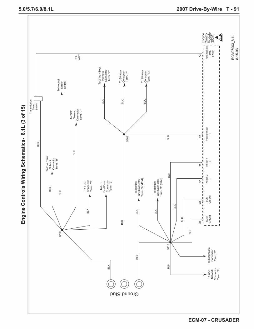
5.0/5.7/6.0/8.1L 2007 Drive-By-Wire T - 91
ECM-07 - CRUSADER
Engi
ne C
ontr
ols
Wiri
ng S
chem
atic
s- 8
.1L
(3 o
f 15)
EC
M07
003_
8.1L
8-
15-0
6
Eng
ine
Con
trol
Mod
ule
(EC
M)
Pad
dlew
heel
(-)
EC
MG
roun
dE
CM
Gro
und
Kno
ck 2
(-)
Kno
ck 1
(-)
8169
3028
26
Tran
smis
sion
Tem
p.S
witc
h
Tran
smis
sion
Tem
p.S
witc
h
54
BLK
BLK
BLK
PP
L\W
HT
BLK
BLK
BLK
BLK
BLK
BLK
BLK
BLK
BLK
BLK
BLK
BLK
Ground Stud
BLK
BLK
BLK
BLK
S10
9
S10
8
S11
0
To 2
0-W
ayC
onne
ctor
Term
. "13
"
To Ig
nitio
nC
oil C
onne
ctor
Term
. "A
" (P
ort)
To Ig
nitio
nC
oil C
onne
ctor
Term
. "A
" (S
tbd)
To C
AN
Net
wor
kC
onne
ctor
Term
. "B
"
To D
iagn
ostic
Con
nect
orTe
rm. "
F"
To 2
0-W
ayC
onne
ctor
Term
. "7"
To 2
-Way
Boa
tH
arne
ssC
onne
ctor
Term
. "2"
To F
uel T
ank
Sol
enoi
dC
onne
ctor
Term
. "B
"To
Neu
tral
Saf
ety
Sw
itch
To T
CP
Sen
sor
Con
nect
orTe
rm. "
7"To
FC
CC
onne
ctor
Term
. "B
"
To L
.P.
Fuel
Pum
pC
onne
ctor
Term
. "2"

T - 92 2007 Drive-By-Wire 5.0/5.7/6.0/8.1L
ECM-07 - CRUSADER
Engi
ne C
ontr
ols
Wiri
ng S
chem
atic
s- 8
.1L
(4 o
f 15)
Eng
ine
Con
trol
Mod
ule
(EC
M)
7184
Igni
tion
Rel
ayFu
el P
ump
Rel
ay C
ontro
l
12
Low
Pre
ssur
eFu
el P
ump
Fuel
Con
trol
Cel
l
Fuel
Tank
Sol
enoi
d
Igni
tion
Rel
ay
EC
M07
004_
8.1L
8-15
-06
BA
BA
To Ig
nitio
nC
oil C
onne
ctor
Term
. "H
" (P
ort)
ToTr
ansm
issi
onTe
mp.
Sw
itch
To Ig
nitio
nC
oil C
onne
ctor
Term
. "H
" (S
tbd)
To F
uel
Inje
ctor
Con
nect
orTe
rm. "
J"
To T
CP
Sen
sor
Con
nect
orTe
rm. "
7"
To
Neu
tral
Saf
ety
Sw
itch
To F
uel
Inje
ctor
Con
nect
orTe
rm. "
K"
To 8
-Way
Boa
t Har
ness
Con
nect
orTe
rm. "
7"
To A
ltern
ator
Con
nect
orTe
rm. "
A"
From
S10
2(Ig
nitio
n)
To S10
8(G
roun
d)
Sta
rter
Sol
enoi
d
Neu
tral
Saf
ety
Sw
itch
YE
L
Sta
rter
Rel
ay
BLK
Not
Use
d
Not
Use
d
30
30
86
8685
85
87A
87A
87
87
Fuel
Pum
pR
elay N
ot U
sed
3086 85
87A
87
RE
D
RE
D/
PP
L
RE
D/
PP
L
PN
K/
YE
L
PN
K/
YE
L
LT B
LU/W
HT
PN
K/
YE
L
PN
K/
YE
L
PP
L
BLK
BLK
BLK
S10
6
S10
4
S11
1
S10
3
S11
2
S10
8
B+
Sta
rter
Sol
enoi
d 100
amp
fuse
RE
D
RE
D
RED
RE
D/
PP
L
WH
T/LT
BLU
PN
K/
DK
GR
N
PN
K/
DK
GR
N
YE
L/R
ED
STA
RTE
RR
ELA
YM
axi
Fuse
20A
IGN
ITIO
NR
ELA
YFu
se 1
5A
FUE
L P
UM
PR
ELA
YM
axi
Fuse
20A

5.0/5.7/6.0/8.1L 2007 Drive-By-Wire T - 93
ECM-07 - CRUSADER
Engi
ne C
ontr
ols
Wiri
ng S
chem
atic
s- 8
.1L
(5 o
f 15)
20-P
in B
oat
Har
ness
Con
nect
or
EC
M07
005_
8.1L
8-15
-06
GR
Y
PN
K
BLK
BLK
PP
L
BLU
/P
NK
BLU
/W
HTB
RN
LT
BLU
/B
LK
PP
LLT G
RN
PN
K/
BLK
BR
N/
PN
K
OR
N
OR
N/
LT B
LU
OR
N/
GR
N
RE
D/
YE
L
GR
Y
12
34
56
78
910
1112
1314
1516
1718
1920
Eng
ine
Con
trol
Mod
ule
(EC
M)
4642
4725
4426
5152
8658
1214
1543
89
S11
3
S10
9
To T
win
Eng
ine
Con
n.Te
rm. "
6"
To T
win
Eng
ine
Con
n.Te
rm. "
5"
S10
1
To 8
-Way
Boa
tC
onn.
Term
. "2"
From
S10
2(Ig
nitio
n)
To 2
-Way
Boa
tH
arne
ssC
onn.
Term
. "2"
To C
AN
Net
wor
kC
onn.
Term
. "C
"
S11
4
Fuel
Leve
l
Pad
dle
Whe
el(+
)
Pad
dle
Whe
el(-
)
RP
M/
MP
HM
ode
Cru
ise
Set
/C
ance
l
Spe
edIn
c/D
ec
Cru
ise
Sta
tus
Lam
p
Spe
edC
ontro
lG
roun
dTA
CH
VG
OV
CA
NB
US
1(+
)
CA
NB
US
1(-
)
Twin
Eng
ine
Syn
c
Syn
cLa
mp/
Ove
rrid
e
Spe
edC
ontro
lIg
nitio
n
TCP
Gai
nS
elec
t
Per
fect
Pas
sR
eque
st
Fuel
Leve
lP
addl
eW
heel
(+)
EC
MG
roun
dR
PM
/M
PH
Mod
e
Cru
ise
Set
/C
ance
l
Spe
edIn
c/D
ec
Cru
ise
Sta
tus
Lam
p
TAC
HV
GO
VC
AN
BU
S 1
(+)
CA
NB
US
1(-
)
Twin
Eng
ine
Syn
c
Syn
cLa
mp/
Ove
rrid
e
TCP
Gai
nS
elec
t
Per
fect
Pas
sR
eque
st
To C
AN
Net
wor
kC
onn.
Term
. "D
"

T - 94 2007 Drive-By-Wire 5.0/5.7/6.0/8.1L
ECM-07 - CRUSADER
Engi
ne C
ontr
ols
Wiri
ng S
chem
atic
s- 8
.1L
(6 o
f 15)
Twin
Eng
ine
Har
ness
Con
nect
or
CA
N T
erm
inat
ion
Con
nect
or/C
ap
CA
N N
etw
ork
Con
nect
or
EC
M07
006_
8.1L
8-15
-06
1513
1511
RE
D/
BLK
RE
D/
BLK
RE
D/
WH
T
RE
D/
WH
T
RE
D/
WH
T
PN
K/
GR
N
PN
K/
GR
N
BLU
/P
NK
BLU
/P
NK
BLU
/W
HT
WH
T/O
RN
BLK
/LT
GR
N
LT G
RN
/R
ED
WH
T/O
RN
OR
N/
WH
T
OR
N/
WH
T
GR
N/
YE
L
OR
N/
YE
L
12
34
56
Eng
ine
Con
trol
Mod
ule
(EC
M)
5556
1416
17
To 2
0-W
ayC
onne
ctor
Term
. "16
"
To S
110
(Gro
und)
To S
110
(Gro
und)
To S
119
(Sen
sor
Gro
und)
To S
105
(BA
T)
To S
105
(BA
T)
To S
118
(5 v
olt)
S11
5
S11
3
To 2
0-W
ayC
onne
ctor
Term
. "17
"
S11
4
CA
NB
US
2(-
)
CA
NB
US
1(-
)
CA
N 1
Term
.C
AN
2Te
rm.
Ser
ial
TxS
eria
lR
xM
aste
r/S
lave
CA
NB
US
2(+
)
CA
NB
US
1(+
)
CA
NB
US
2(-
)
CA
NB
US
1(-
)M
aste
r/S
lave
CA
NB
US
2(+
)
CA
NB
US
1(+
)
1 2 3 4D
iagn
ostic
Con
nect
or
A
AB
CD
EF
B C D E F 1 2 3 4
Twis
ted
Twis
ted

5.0/5.7/6.0/8.1L 2007 Drive-By-Wire T - 95
ECM-07 - CRUSADER
Engi
ne C
ontr
ols
Wiri
ng S
chem
atic
s- 8
.1L
(7 o
f 15)
B
Fuel
Inje
ctor
Driv
er 7
Fuel
Inje
ctor
Driv
er 1
Fuel
Inje
ctor
Driv
er 5
Fuel
Inje
ctor
Driv
er 3
Fuel
Inje
ctor
Driv
er 6
Fuel
Inje
ctor
Driv
er 8
Fuel
Inje
ctor
Driv
er 4
Fuel
Inje
ctor
Driv
er 2
Eng
ine
Con
trol
Mod
ule
(EC
M)
PN
K/
DK
GR
N
PN
KP
NK
PN
K
TAN
/LT
BLU
GR
YG
RY
/Y
EL
TAN
/G
RN
TAN
/O
RN
GR
Y/
BLU
TAN
/B
RN
TAN
/Y
EL
PN
KP
NK
PN
KP
NK
PN
K
A AC
EG
KJ
HD
FB
67
Fuel
Inje
ctor
Cyl
inde
r #1
B A
Fuel
Inje
ctor
Cyl
inde
r #4
B A
Fuel
Inje
ctor
Cyl
inde
r #6
B A
Fuel
Inje
ctor
Cyl
inde
r #7
6563
61
A
66
Fuel
Inje
ctor
Cyl
inde
r #2
BB
A
Fuel
Inje
ctor
Cyl
inde
r #3
B A
Fuel
Inje
ctor
Cyl
inde
r #5
B A
Fuel
Inje
ctor
Cyl
inde
r #8
6268
64
S11
1
S11
6S
117
EC
M07
007_
8.1L
8-15
-06
To Ig
nitio
n C
oil
Con
nect
or (o
dd c
yl.)
Term
. "H
"To
Igni
tion
Coi
lC
onne
ctor
(eve
n cy
l.)Te
rm. "
H"
From
Igni
tion
Rel
ay T
erm
. "87

T - 96 2007 Drive-By-Wire 5.0/5.7/6.0/8.1L
ECM-07 - CRUSADER
Engi
ne C
ontr
ols
Wiri
ng S
chem
atic
s- 8
.1L
(8 o
f 15)
7
4019
2022
2441
BAC
Man
ifold
Abs
olut
eP
ress
ure
(MA
P)
Sen
sor
Eng
ine
Coo
lant
Tem
pera
ture
(EC
T) S
enso
r
Eng
ine
Con
trol
Mod
ule
(EC
M)
Map
Sen
sor
Sig
nal
Cra
nkS
enso
r(-
)
Sen
sor
Gro
und
CA
MS
enso
r(-
)
Exh
aust
Gas
Tem
p.S
witc
h
Oil
Pre
ssur
eS
enso
rS
igna
l
EC
TS
enso
rS
igna
l
IAT
Sen
sor
Sig
nal
Eng
ine
Con
trol
Mod
ule
(EC
M)
39
A B
Inta
ke A
irTe
mpe
ratu
re(IA
T) S
enso
r
A B
S11
8
S11
9
S12
0
EC
M07
008_
8.1L
8-15
-06
LT G
RN
/R
ED
LT G
RN
/R
ED
TAN
/W
HT
YE
L/G
RY
LT G
RN
/R
ED
LT G
RN
/R
ED
LT G
RN
/R
ED
BLK
/LT
GR
N
BLK
/LT GR
N
BLK
/LT GR
N
LT G
RN
/R
ED
5 V
olt
Ref
eren
ce
53
Exh
aust
Tem
p.S
witc
h(s
tbd)
Exh
aust
Tem
p.S
witc
h(p
ort)
Oil
Pre
ssur
eS
enso
rC
AB
To P
ort I
gniti
on C
oil C
onn.
Ter
m. "
E"
To T
hrot
tle
Bod
y C
onn.
Term
. "B
"
To T
hrot
tle
Bod
y C
onn.
Term
. "H
"
To S
TBD
Igni
tion
Coi
l Con
n. T
erm
. "E
"
To C
AM
Pos
ition
Sen
sor C
onn.
Ter
m. "
B"
To C
rank
Pos
ition
Sen
sor C
onn.
Ter
m. "
B"
To D
iagn
ostic
Con
n. T
erm
. "A
"
Kno
ckS
enso
r 1S
igna
l
BLK
/Y
EL
(6.0
L on
ly)
Kno
ckS
enso
r 2S
igna
l
2729
BLK
/W
HT TA
N/
RE
D
LT BLU
LT GR
N
Kno
ckS
enso
r 1(K
S)
Kno
ckS
enso
r 2(K
S)
AB
To T
CP
Sen
sor
Con
n. T
erm
. "6"
To C
rank
Sen
sor C
onn.
Term
. "A
"
To C
AM
Sen
sor C
onn.
Term
. "A
"
To D
iag.
Con
n.Te
rm. "
B"

5.0/5.7/6.0/8.1L 2007 Drive-By-Wire T - 97
ECM-07 - CRUSADER
Engi
ne C
ontr
ols
Wiri
ng S
chem
atic
s- 8
.1L
(9 o
f 15)
19
A Th
rottl
e P
ositi
on (T
P) S
enso
r/Act
uato
r(T
hrot
tle B
ody)
Eng
ine
Con
trol
Mod
ule
(EC
M)
Mot
or(+
)M
otor
(-)
RE
F1G
roun
dR
EF1
Gro
und
RE
F1G
roun
dR
EF
2G
roun
d
TPS
enso
r 1S
igna
l
TPS
enso
r 2S
igna
l
5 V
olt
RE
F 1
5 V
olt
RE
F 1
5 V
olt
RE
F 2
5 V
olt
RE
F 1
Mot
or(+
)M
otor
(-)
Sen
sor
Gro
und
TPS
enso
r 1S
igna
l
TPS
enso
r 2S
igna
l
Eng
ine
Con
trol
Mod
ule
(EC
M)
8283
206
5
B
C
D
E
FG
H
EC
M07
009_
8.1L
8-15
-06
5 V
olt
RE
F 1
495 V
olt
RE
F 2
PN
K/
WH
T
LT GR
N/
RE
D
LT GR
N/
PP
L
TAN
/O
RN
BLK
/LT G
RN
BLK
/LT G
RN
BLK
/LT G
RN
LT BLU
/B
LU
PP
L/LT B
LU
LT GR
N/
RE
D
LT GR
N/
RE
D
S11
9
S11
8
Thro
ttle
Con
trol
Pos
ition
(TC
P) S
enso
r/TC
PS
enso
r 2S
igna
l
TCP
Sen
sor 1
Sig
nal
Gro
und
Idle
Val
idat
ion
Sw
itch
TCP
Sen
sor 2
Sig
nal
TCP
Sen
sor 1
Sig
nal
Idle
Val
idat
ion
Sw
itch
RE
F 2
Gro
und
1050
6
3 5
12
OR
N/
BLK
DK
BLU
/O
RN 9
8
PP
L/Y
EL 48
7
BLK
LT GR
N/
BLK
4
To S
108
(Gro
und)

T - 98 2007 Drive-By-Wire 5.0/5.7/6.0/8.1L
ECM-07 - CRUSADER
Engi
ne C
ontr
ols
Wiri
ng S
chem
atic
s- 8
.1L
(10
of 1
5)
CrankSensor
(+)
CAMSensor
(+)
CrankSensor
(-)
CAMSensor
(-)
5 VoltReference
CamshaftPosition(CMP)Sensor
EngineControlModule(ECM)
ECM07010_8.1L8-15-06
SolidState
19 242221 23
AA
CC
BB
CrankshaftPosition(CKP)Sensor
SolidState
ECMGround
20
PPL/ORN
BLK/LT GRN
BLK/LT GRN
LT GRN/RED
LTGRN/RED
PPL/WHT
WHT/PPL
GRY/BRN
S118
S119
S121 S122
Twisted
8.1L Engine
Twisted
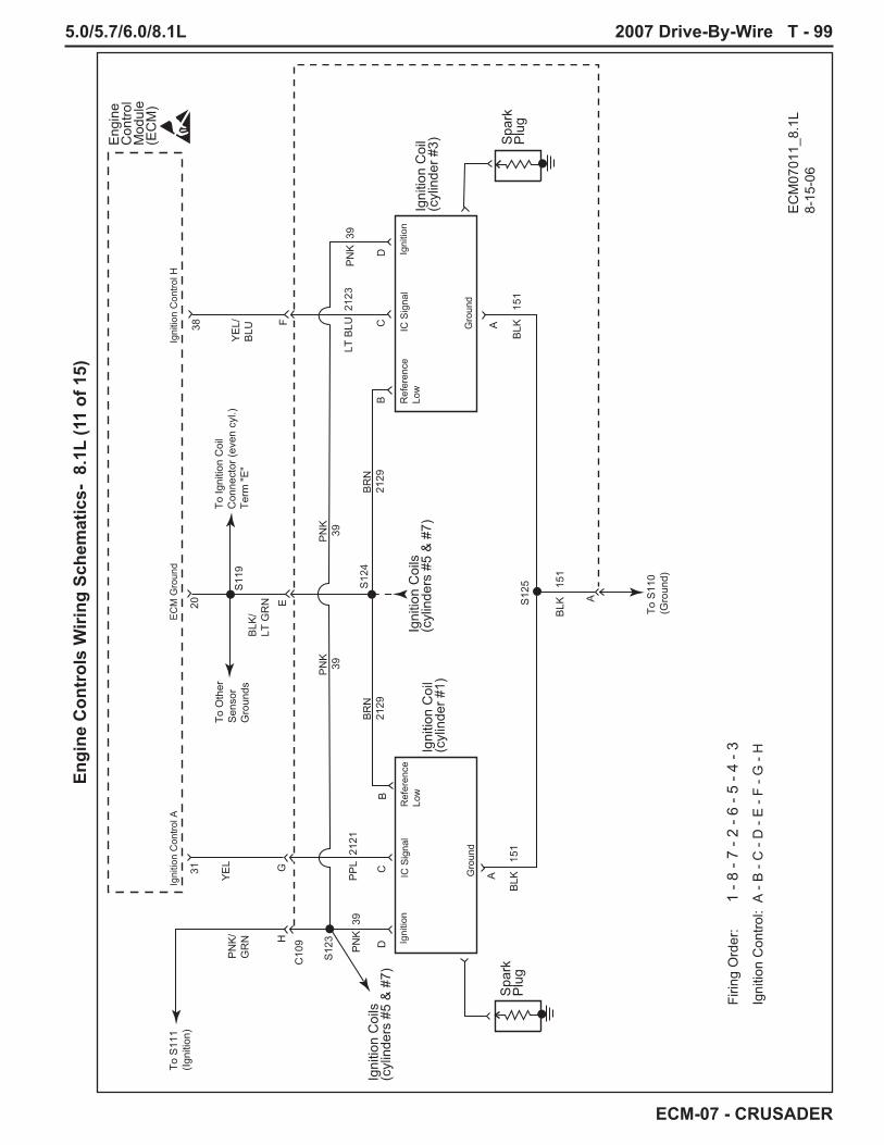
5.0/5.7/6.0/8.1L 2007 Drive-By-Wire T - 99
ECM-07 - CRUSADER
Engi
ne C
ontr
ols
Wiri
ng S
chem
atic
s- 8
.1L
(11
of 1
5)
38
EC
M G
roun
dIg
nitio
n C
ontro
l AIg
nitio
n C
ontro
l H
Spa
rkP
lug
Spa
rkP
lug
Igni
tion
Coi
l(c
ylin
der #
1)
Firin
g O
rder
:
1 -
8 - 7
- 2
- 6 -
5 - 4
- 3
Igni
tion
Con
trol:
A -
B -
C -
D -
E -
F - G
- H
Igni
tion
Coi
ls(c
ylin
ders
#5
& #
7)
Igni
tion
Coi
ls(c
ylin
ders
#5
& #
7)
Igni
tion
Coi
l(c
ylin
der #
3)Eng
ine
Con
trol
Mod
ule
(EC
M)
BLK
15
1
BLK
15
1 B
LK
151
BR
N
2129
BR
N
2129
BLK
/LT
GR
N
PN
K/
GR
NY
EL/
BLU
LT B
LU 2
123
YE
L
PP
L 2
121
PN
K 3
9P
NK
39
PN
K 3
9P
NK
39
C10
9
S12
4
S11
9
S12
5
S12
3
EC
M07
011_
8.1L
8-15
-06
Igni
tion
Ref
eren
ce
Low
IC S
igna
l
Gro
und
Igni
tion
Ref
eren
ce
Low
IC S
igna
l
Gro
und
2031 A
DD
CGH
E A
F
BB
C A
To S
110
(Gro
und)
To Ig
nitio
n C
oil
Con
nect
or (e
ven
cyl.)
Term
"E"
To S
111
(Igni
tion)
To O
ther
Sen
sor
Gro
unds

T - 100 2007 Drive-By-Wire 5.0/5.7/6.0/8.1L
ECM-07 - CRUSADER
Engi
ne C
ontr
ols
Wiri
ng S
chem
atic
s- 8
.1L
(12
of 1
5)
35
EC
M G
roun
dIg
nitio
n C
ontro
l FIg
nitio
n C
ontro
l C
Spa
rkP
lug
Spa
rkP
lug
Igni
tion
Coi
l(c
ylin
der #
5)
Firin
g O
rder
:
1 -
8 - 7
- 2
- 6 -
5 - 4
- 3
Igni
tion
Con
trol:
A -
B -
C -
D -
E -
F - G
- H
Igni
tion
Coi
ls(c
ylin
ders
#1
& #
3)
Igni
tion
Coi
ls(c
ylin
ders
#1
& #
3)
Igni
tion
Coi
l(c
ylin
der #
7)Eng
ine
Con
trol
Mod
ule
(EC
M)
BLK
15
1
BLK
15
1 B
LK
151
BR
N
2129
BR
N
2129
BLK
/LT
GR
N
PN
K/
GR
NY
EL/
WH
T
LT B
LU 2
123
YE
L/G
RN
PP
L 2
121
PN
K 3
9P
NK
39
PN
K 3
9P
NK
39
C10
9
S12
4
S11
9
S12
5
S12
3
EC
M07
012_
8.1L
8-15
-06
Igni
tion
Ref
eren
ce
Low
IC S
igna
l
Gro
und
Igni
tion
Ref
eren
ce
Low
IC S
igna
l
Gro
und
2034 A
DD
CCH
E A
B
BB
C A
To S
110
(Gro
und)
To Ig
nitio
n C
oil
Con
nect
or (e
ven
cyl.)
Term
"E"
To S
111
(Igni
tion)
To O
ther
Sen
sor
Gro
unds

5.0/5.7/6.0/8.1L 2007 Drive-By-Wire T - 101
ECM-07 - CRUSADER
Engi
ne C
ontr
ols
Wiri
ng S
chem
atic
s- 8
.1L
(13
of 1
5)
36
EC
M G
roun
dIg
nitio
n C
ontro
l DIg
nitio
n C
ontro
l G
Spa
rkP
lug
Spa
rkP
lug
Igni
tion
Coi
l(c
ylin
der #
2)
Firin
g O
rder
:
1 -
8 - 7
- 2
- 6 -
5 - 4
- 3
Igni
tion
Con
trol:
A -
B -
C -
D -
E -
F - G
- H
Igni
tion
Coi
ls(c
ylin
ders
#6
& #
8)
Igni
tion
Coi
ls(c
ylin
ders
#6
& #
8)
Igni
tion
Coi
l(c
ylin
der #
4)Eng
ine
Con
trol
Mod
ule
(EC
M)
BLK
15
1
BLK
15
1 B
LK
151
BR
N
2129
BR
N
2129
BLK
/LT
GR
N
PN
K/
GR
NW
HT/
BLK
LT B
LU 2
123
WH
T/B
RN
PP
L 2
121
PN
K 3
9P
NK
39
PN
K 3
9P
NK
39
C11
0
S12
4
S11
9
S12
5
S12
3
EC
M07
013_
8.1L
8-15
-06
Igni
tion
Ref
eren
ce
Low
IC S
igna
l
Gro
und
Igni
tion
Ref
eren
ce
Low
IC S
igna
l
Gro
und
2037 A
DD
CBH
E A
C
BB
C A
To S
110
(Gro
und)
To Ig
nitio
n C
oil
Con
nect
or (o
dd c
yl.)
Term
"E"
To S
111
(Igni
tion)
To O
ther
Sen
sor
Gro
unds

T - 102 2007 Drive-By-Wire 5.0/5.7/6.0/8.1L
ECM-07 - CRUSADER
Engi
ne C
ontr
ols
Wiri
ng S
chem
atic
s- 8
.1L
(14
of 1
5)
33
EC
M G
roun
dIg
nitio
n C
ontro
l EIg
nitio
n C
ontro
l B
Spa
rkP
lug
Spa
rkP
lug
Igni
tion
Coi
l(c
ylin
der #
6)
Firin
g O
rder
:
1 -
8 - 7
- 2
- 6 -
5 - 4
- 3
Igni
tion
Con
trol:
A -
B -
C -
D -
E -
F - G
- H
Igni
tion
Coi
ls(c
ylin
ders
#2
& #
4)
Igni
tion
Coi
ls(c
ylin
ders
#2
& #
4)
Igni
tion
Coi
l(c
ylin
der #
8)Eng
ine
Con
trol
Mod
ule
(EC
M)
BLK
15
1
BLK
15
1 B
LK
151
BR
N
2129
BR
N
2129
BLK
/LT
GR
N
PN
K/
GR
NW
HT/
GR
N
LT B
LU 2
123
WH
T/R
ED
PP
L 2
121
PN
K 3
9P
NK
39
PN
K 3
9P
NK
39
C11
0
S12
4
S11
9
S12
5
S12
3
EC
M07
014_
8.1L
8-15
-06
Igni
tion
Ref
eren
ce
Low
IC S
igna
l
Gro
und
Igni
tion
Ref
eren
ce
Low
IC S
igna
l
Gro
und
2032 A
DD
CFH
E A
G
BB
C A
To S
110
(Gro
und)
To Ig
nitio
n C
oil
Con
nect
or (o
dd c
yl.)
Term
"E"
To S
111
(Igni
tion)
To O
ther
Sen
sor
Gro
unds

5.0/5.7/6.0/8.1L 2007 Drive-By-Wire T - 103
ECM-07 - CRUSADER
Engi
ne C
ontr
ols
Wiri
ng S
chem
atic
s- 8
.1L
(15
of 1
5)
EC
M07
015_
8.1L
8-15
-06
Igni
tion
Con
trol H
38
Igni
tion
Con
trol A
Cyl
inde
r#1
Cyl
inde
r#3
Cyl
inde
r#5
Cyl
inde
r#7
Cyl
inde
r#2
Cyl
inde
r#4
Cyl
inde
r#6
Cyl
inde
r#8
31
BLK
YE
L/W
HT
YE
L/G
RN
YE
L/B
LUY
EL
PN
K/
GR
N
PN
K/
GR
N
AB
CD
EF
GH
Eng
ine
Con
trol
Mod
ule
(EC
M)
Igni
tion
Con
trol C
35
Igni
tion
Con
trol F
Igni
tion
Con
trol E
Igni
tion
Con
trol B
Igni
tion
Con
trol D
Igni
tion
Con
trol G
34
3233
3736
Not
Use
d
Not
Use
d
Igni
tion
Coi
lC
onne
ctor
(eve
n cy
l.)
Igni
tion
Coi
lC
onne
ctor
(odd
cyl
.)
BLK
WH
T/B
RN
WH
T/ B
LKW
HT/
RE
DW
HT/
GR
N
AB
CD
EF
GH
To S11
0(G
roun
d)
To S11
0(G
roun
d)
From
Igni
tion
Rel
ayTe
rm. "
87"
To In
ject
ors
S11
1
To O
ther
Sen
sor
Gro
unds
To O
ther
Sen
sor
Gro
unds
EC
M G
roun
d
EC
M G
roun
d
BLK
/LT
GR
N
BLK
/LT
GR
N
S11
9
2020
S11
9

T - 104 2007 Drive-By-Wire 5.0/5.7/6.0/8.1L
ECM-07 - CRUSADER
Sync/Cruise Switch Panel (RA152007)
RA1520079-28-06
ORN/GRN
ORN/BLU
BRN
BLK
BLK BLK
PPL
PPLPPL
BRN
ORN
ORN
LTBLU/BLK
LTBLU/BLK
RED/YEL
RED/YEL
Sync/Cruise
Speed Speed
(+) /Resume
SETON
OFF CANCEL (-)
5KResistorSync
LEDCruiseLED
CircuitBoard
FromIgnition
ToGround
Deutsch 12-Way ConnectorP/N - DT06-12S
910121138
CruiseLED
(Ground)
SyncLED
(Ground)
CruiseRequest
SyncRequest
SpeedSet/
Cancel
SpeedIncrement/Decrement
Note: Panel 12-Way connector plugs directly into the following Crusader supplied Boat Speed Control Harnesses:RA121091RA121091ARA121097-07RA121097-15RA121097-21***See the following pages for schematics of these harnesses.

5.0/5.7/6.0/8.1L 2007 Drive-By-Wire T - 105
ECM-07 - CRUSADER
BLK/WHT
WHT
ORN
ORN/LTBLU
RED/YEL
LTBLU/BLK
ORN/GRN
BRN
Deutsch 20-Way ConnectorP/N - HDP26-18-20SN
Deutsch 3-WayConnector
P/N - DT06-3S
Crusader supplied Boat Speed Control HarnessesRA121091 = 25 ft
RA121091A = 45 ft
16 17 8 9 10 11 18 19
11 10 9 8 12 3
CAN 1BUS(+)
CAN 1BUS(-)
A B
CAN 1BUS(+)
CAN 1BUS(-)
CruiseRequest
SpeedSet/
Cancel
SpeedIncrement/Decrement
CruiseLED
(Ground)
SyncRequest
SyncLED
(Ground)
CruiseRequest
SpeedSet/
Cancel
SpeedIncrement/Decrement
CruiseLED
(Ground)Sync
Request
SyncLED
(Ground)
Deutsch 12-WayConnector
P/N - DT04-12PA
RA121091_091A9-28-06
Twisted

T - 106 2007 Drive-By-Wire 5.0/5.7/6.0/8.1L
ECM-07 - CRUSADER
TAN
TAN/BLK
PPL
GRN/YEL
BLUBLK
YEL/RED
RED
Deutsch 8-Way ConnectorP/N - DT04-8PA
Deutsch 2-WayConnector
P/N - DTP04-2P
Crusader supplied Boat Extension HarnessesRA121092 = 25 ft
RA121092A = 45 ft***Extension harnesses are used to connect engine
wiring to the helm.
3 4 5 6 7 81 2
CoolantTemperature
Sender
Buzzer IgnitionFeed
MalfunctionIndicator
Lamp (MIL)
StarterCircuit
OilPressureSender
Battery(PanelPower)
Ground(Panel)
GRY
2
TACH
RA121092_092A9-28-06
Spliced at Helm by Installer

5.0/5.7/6.0/8.1L 2007 Drive-By-Wire T - 107
ECM-07 - CRUSADER
TAN
TAN/BLK
PPL
GRN/YEL
BLUBLK
YEL/RED
RED/PPL
Deutsch 8-Way ConnectorP/N - DT04-8PA
8-Way FemaleMolded Connector
Deutsch 2-WayConnector
P/N - DTP04-2P
Crusader supplied Boat Extension HarnessRA121092B = 25 ft
***Extension harnesses are used to connect engine wiring to the helm.
3 4 5 67 81 2
CoolantTemperature
Sender
Buzzer IgnitionFeed
MalfunctionIndicator
Lamp (MIL)
StarterCircuit
OilPressureSender
Battery(PanelPower)
Ground(Panel)
GRY
2
TACH
8 4 6 3 75 1
CoolantTemperature
Sender BuzzerIgnitionFeed
StarterCircuit
OilPressureSender
TerminatedBy
Installer
Battery(PanelPower)
Ground(Panel)
2
TACH
RA121092B9-28-06

T - 108 2007 Drive-By-Wire 5.0/5.7/6.0/8.1L
ECM-07 - CRUSADER
TAN
TAN/BLK
PPL
GRN/YEL
BLUBLK
YEL/RED
RED/PPL
Deutsch 8-Way ConnectorP/N - DT04-8PA
Deutsch 2-WayConnector
P/N - DTP04-2P
Crusader supplied Boat Extension HarnessRA121092C = 25 ft
***Extension harnesses are used to connect engine wiring to the helm.
***This harness may be used if application requires additional oil and temp. sending units to be used.
4 5 6 71 2
To CoolantTemperature
Sender
Buzzer IgnitionFeed
MalfunctionIndicator
Lamp (MIL)
StarterCircuit
To OilPressureSender
Battery(PanelPower)
Ground(Panel)
GRY
2
TACH
RA121092C9-28-06
Spliced at Helm by Installer

5.0/5.7/6.0/8.1L 2007 Drive-By-Wire T - 109
ECM-07 - CRUSADER
WHT
BLK/WHT
ORN
ORN/LTBLU
RED/YEL
LTBLU/BLK
ORN/GRN
BRN
Deutsch 20-Way ConnectorP/N - HDP26-18-20SN
Deutsch 8-Way ConnectorP/N - DT04-8PA
Crusader supplied Boat Speed Control Extension Harnesses
RA121096-20 = 20 ftRA121096-25 = 25 ftRA121096-30 = 30 ftRA121096-35 = 35 ft
***Extension harnesses are used with various lengths of RA121097 harnesses.
16 17 8 9 10 11 18 19
7 8 1 4 2 3 6 5
CAN 1BUS(+)
CAN 1 BUS (-)
CruiseRequest
SpeedSet/
Cancel
SpeedIncrement/Decrement
CruiseLED
(Ground)
SyncRequest
SyncLED
(Ground)
CAN 1BUS(+)
CAN 1 BUS (-)
CruiseRequest
SpeedSet/
Cancel
SpeedIncrement/Decrement
CruiseLED
(Ground)Sync
Request
SyncLED
(Ground)
RA1210969-28-06
Twisted

T - 110 2007 Drive-By-Wire 5.0/5.7/6.0/8.1L
ECM-07 - CRUSADER
WHT
BLK/WHT
ORN
ORN/LTBLU
RED/YEL
LTBLU/BLK
ORN/GRN
BRN
Deutsch 8-Way ConnectorP/N - DT06-8SA
Deutsch 3-WayConnector
P/N - DT06-3S
Crusader supplied Boat Speed Control Extension Harnesses
RA121097-07 = 7 ftRA121097-15 = 15 ftRA121097-21 = 21 ft
***Extension harnesses are used with various lengths of RA121096 harnesses.
7 8 1 4 2 3 6 5
11 10 9 8 12 3
CAN 1BUS(+)
CAN 1 BUS (-)
A B
CAN 1BUS(+)
CAN 1 BUS (-)
CruiseRequest
SpeedSet/
Cancel
SpeedIncrement/Decrement
CruiseLED
(Ground)
SyncRequest
SyncLED
(Ground)
CruiseRequest
SpeedSet/
Cancel
SpeedIncrement/Decrement
CruiseLED
(Ground)Sync
Request
SyncLED
(Ground)
Deutsch 12-WayConnector
P/N - DT04-12PA
RA1210979-28-06
Twisted

5.0/5.7/6.0/8.1L 2007 Drive-By-Wire T - 111
ECM-07 - CRUSADER
Par
t N
um
ber
-
Cru
sad
er
RP
M C
ruis
e O
nly
Twin
En
gin
e S
ynch
ron
izat
ion
CA
N B
US
Dis
pla
ys
Engine SideD a s h S i d e
2007
En
gin
e / B
oat
/ S
pee
d C
on
tro
l / C
AN
-Bu
s H
arn
esse
s
Par
t N
um
ber
-
RA
1520
07
AB
CA
N B
US
1 C
onne
ctor
Info
rmat
ion
Deu
tsch
3-W
ay R
ecep
tacl
eP/
N:
DT0
6-3S
Wed
ge L
ock:
W3S
-193
9
AB
1 2 3
4 5 6
+ B
atte
ry
- Gro
und
1 2 3
4 5 6
Mur
phy
Supp
lied
Equi
pmen
tSe
e yo
ur D
istr
ibut
or/
Dea
ler f
or th
e ki
tyo
u re
quire
.
STA
RB
OA
RD
/M
AST
EREN
GIN
E
POR
T/SL
AVE
ENG
INE
GN
D
Master / Slave Engine Harness Part Number - RA121072C
+ B
atte
ry
- Gro
und
Wire
Pin
Col
or
Func
tion
A
Blk
/Wht
C
AN
1 (+
)
B
Whi
te
C
AN
1 (-
)
C
Plu
g
All
Bo
at A
pp
licat
ion
sB
AT
/ G
rou
nd
/ S
tart
er /
Ign
itio
nO
il P
ress
ure
/Co
ola
nt
Tem
p G
aug
es/B
uzz
er
Par
t N
um
ber
-
RA
1210
92 -
25
FT,
Un
term
inat
edR
A12
1092
A -
45
FT,
Un
term
inat
edR
A12
1092
B -
25
FT,
Ter
min
ated
w/8
-Pin
(F
)- C
arve
rR
A12
1092
C -
25
FT,
W/V
DO
Sen
der
tak
e-o
uts
- H
acke
r
Par
t N
um
ber
-R
A12
1093
Par
t N
um
ber
-R
A12
1094
Par
t N
um
ber
-
RA
1210
94A
AD
AP
TE
R H
AR
NE
SS
ES
F
or
Rep
ow
er a
nd
use
wit
h a
n
exis
tin
g b
oat
har
nes
s
Syn
cC
ruis
e
Spe
ed
Can
cel
Set
OFFON
Syn
/Cru
(-)
(+)/R
es
Spe
ed
+ B
atte
ry
- Gro
und
Par
t N
um
ber
-
RA
1210
98
RA
1210
91 -
25 F
T, E
ngin
e to
Pan
elR
A12
1091
A - 4
5 FT
, Eng
ine
to P
anel
RA
1210
96-2
0, E
ngin
e to
Jun
ctio
n (2
0 fo
ot)
RA
1210
96-2
5, E
ngin
e to
Jun
ctio
n (2
5 fo
ot)
RA
1210
96-3
0, E
ngin
e to
Jun
ctio
n (3
0 fo
ot)
RA
1210
96-3
5, E
ngin
e to
Jun
ctio
n (3
5 fo
ot)
RA
1210
97-0
7, J
unct
ion
to P
anel
(7 fo
ot)
RA
1210
97-1
5, J
unct
ion
to P
anel
(15
foot
)R
A12
1097
-21,
Jun
ctio
n to
Pan
el (2
1 fo
ot)
10-P
inR
ound
Mol
ded
8-Pi
n (F
)
8-Pi
n (M
)
14-P
inM
erc
Styl
e
RK
1790
08 -
Che
ck E
ngin
e La
mp
(MIL
) Kit
-La
mp
and
Ala
rm B
uzze
r
Mur
phy
Hel
mVi
ew
OR
Par
t N
um
ber
-R
A12
1093
A
10-P
inR
ound
Mol
ded
W/V
DO
take
-out
s

T - 112 2007 Drive-By-Wire 5.0/5.7/6.0/8.1L
ECM-07 - CRUSADER
Cru
sad
er R
epo
wer
RP
M C
ruis
e O
nly
Twin
En
gin
e S
ynch
ron
izat
ion
CA
N B
US
Dis
pla
ys
Engine Side
Dash Side
2007
Sp
eed
Co
ntr
ol /
CA
N-B
us
Bo
at H
arn
esse
s
Par
t N
um
ber
-
RA
1520
07
Par
t N
um
ber
-
RA
1210
91 -
25 F
T, E
ngin
e to
Pan
elR
A12
1091
A - 4
5 FT
, Eng
ine
to P
anel
RA
1210
96-2
0, E
ngin
e to
Jun
ctio
n (2
0 fo
ot)
RA
1210
96-2
5, E
ngin
e to
Jun
ctio
n (2
5 fo
ot)
RA
1210
96-3
0, E
ngin
e to
Jun
ctio
n (3
0 fo
ot)
RA
1210
96-3
5, E
ngin
e to
Jun
ctio
n (3
5 fo
ot)
RA
1210
97-0
7, J
unct
ion
to P
anel
(7 fo
ot)
RA
1210
97-1
5, J
unct
ion
to P
anel
(15
foot
)R
A12
1097
-21,
Jun
ctio
n to
Pan
el (2
1 fo
ot)
Syn
cC
ruis
e
Spe
ed
Can
cel
Set
OFFON
Syn
/Cru
(-)
(+)/R
es
Spe
ed
OR
OP
TIO
NA
L -
Mul
tifun
ctio
nC
AN
-Bus
Dis
play
sor
Inst
umen
tatio
n

5.0/5.7/6.0/8.1L 2007 Drive-By-Wire T - 113
ECM-07 - CRUSADER
Cab
les
Sta
ndar
d M
echa
nica
l Han
dle
- C
able
ope
rate
d th
rottl
e -
Cab
le o
pera
ted
shift
App
licat
ion(
s) -
ALL
Cab
le O
pera
ted
TCP
Sen
sor
Twin
Eng
ine
Wiri
ng
Cab
les
1. T
win
Eng
ine
Syn
chro
niza
tion
2. R
PM
Bas
ed C
ruis
e C
ontro
l3.
Incr
emen
t Spe
ed4.
Dec
rem
ent S
peed
5. R
esum
e Fe
atur
e
2007
Cru
sade
r Ele
ctro
nica
lly C
ontro
lled
Twin
Eng
ine
Con
figur
atio
n(E
ngin
e-M
ount
ed T
CP
Sen
sors
)
EC
ME
CM
Cru
sade
r Cru
ise/
Sync
Con
trol
(OPT
ION
AL)
Pow
erVi
ews
Syn
cC
ruis
e
Spe
ed
Can
cel
Set
OFFON
Syn
/Cru
(-)
(+)/R
es
Spe
ed

T - 114 2007 Drive-By-Wire 5.0/5.7/6.0/8.1L
ECM-07 - CRUSADER
Engine Side
Dash Side
All
Bo
at A
pp
licat
ion
sB
AT
/ G
rou
nd
/ S
tart
er /
Ign
itio
n
Oil
Pre
ssu
re/C
oo
lan
t Te
mp
Gau
ges
/Bu
zzer
TOG
AU
GE
S
2007
Bo
at H
arn
esse
s
Par
t N
um
ber
-
RA
1210
92 -
25
FT,
Un
term
inat
edR
A12
1092
A -
45
FT,
Un
term
inat
edR
A12
1092
B -
25
FT,
Ter
min
ated
w/8
-Pin
(F
)- (
Car
ver)
RA
1210
92C
- 2
5 F
T, W
/VD
O S
end
er t
ake-
ou
ts -
(H
acke
r)

5.0/5.7/6.0/8.1L 2007 Drive-By-Wire T - 115
ECM-07 - CRUSADER
Engine Side
Dash Side
2007
Bo
at A
dap
ter
Har
nes
ses
Par
t N
um
ber
-R
A12
1093
Par
t N
um
ber
-R
A12
1094
Par
t N
um
ber
-
RA
1210
94A
Par
t N
um
ber
-
RA
1210
98
10-P
inR
ound
Mol
ded
8-Pi
n (F
)
8-Pi
n (M
)
14-P
inM
erc
Styl
e
Par
t N
um
ber
-R
A12
1093
A
10-P
inR
ound
Mol
ded
W/V
DO
Sen
sor l
eads

T - 116 2007 Drive-By-Wire 5.0/5.7/6.0/8.1L
ECM-07 - CRUSADER
MO
DE
L M
P 5
.0L
MP
5.7
L M
P 8
.1L
(STD
) M
P 8
.1L
(HO
) M
P 6
.0L
Car
b 5.
7L (
Hor
sepo
wer
) (2
75 H
P)
(330
HP
) (3
85 H
P)
(425
HP
) (3
75 H
P)
(300
HP
)
Dis
plac
emen
t 5.
0L (3
05 C
ID)
5.7L
(350
CID
) 8.
1L (4
96 C
ID)
8.1L
(496
CID
) 6.
0L (3
64 C
ID)
5.7L
(350
CID
)
Bor
e 3.
75 in
. (95
.0 m
m)
4.0
in. (
101.
6 m
m)
4.25
in. (
107.
95 m
m)
4.25
in. (
107.
95 m
m)
4.00
07 in
. (10
1.61
8 m
m)
4.0
in. (
101.
6 m
m)
Str
oke
3.48
in. (
88.3
mm
) 3.
48 in
. (88
.3 m
m)
4.37
0 in
. (11
1.0
mm
) 4.
370
in. (
111.
0 m
m)
3.62
2 in
. (92
.0 m
m)
3.48
in. (
88.3
mm
)
Com
pres
sion
Rat
io
9.4:
1 9.
4:1
9.1:
1 9.
1:1
9.4:
1 9.
4:1
Com
pres
sion
Pre
ssur
e 13
0 - 2
15 p
si
130
- 215
psi
13
0 - 1
75 p
si
130
- 175
psi
13
0 - 2
15 p
si
130
- 215
psi
WO
T O
pera
ting
RP
M
4600
-500
0 48
00 -
5200
44
00 -
4800
48
00 -
5200
48
00 -
5300
48
00 -
5200
Pre
ferr
ed W
OT
RP
M
4800
50
00
4600
50
00
5200
50
00
Cru
isin
g R
PM
(Max
) 38
00
4000
38
00
4000
40
00
4000
Idl
e R
PM
(In
Gea
r)
650
(Not
Adj
usta
ble)
65
0 (N
ot A
djus
tabl
e)
650
(Not
Adj
usta
ble)
70
0 (N
ot A
djus
tabl
e)
650
(Not
Adj
usta
ble)
75
0
Oil
Pre
ssur
e @
25
- 60
psi
25
- 60
psi
25
- 60
psi
25
- 60
psi
25
- 80
psi
25
- 60
psi
200
0 R
PM
(1
72 -
414
kPa)
(1
72 -
414
kPa)
(1
72 -
414
kPa)
(1
72 -
414
kPa)
(1
72 -
552
kPa)
(1
72 -
414
kPa)
Min
imum
Oil
Pre
ssur
e 10
psi
(69
kPa)
10
psi
(69
kPa)
10
psi
(69
kPa)
10
psi
(69
kPa)
10
psi
(69
kPa)
10
psi
(69
kPa)
at
Idle
at
Idle
at
Idle
at
Idle
at
Idle
at
Idle
Spa
rk P
lug
P/N
R
0300
10
R03
0010
R
0300
09
R03
0009
R
0300
11
R03
0010
Spa
rk P
lug
Gap
0.
060
in.
0.06
0 in
. 0.
060
in.
0.06
0 in
. 0.
060
in.
0.06
0 in
. F
irin
g O
rder
1-
8-4-
3-6-
5-7-
2 (L
H)
1-8-
4-3-
6-5-
7-2
(LH
) 1-
8-7-
2-6-
5-4-
3 (L
H)
1-8-
7-2-
6-5-
4-3
(LH
) 1-
8-7-
2-6-
5-4-
3 (L
H)
1-8-
4-3-
6-5-
7-2
(LH
)
1-2-
7-5-
6-3-
4-8
(RH
) 1-
2-7-
5-6-
3-4-
8 (R
H)
NA
N
A
NA
1-
2-7-
5-6-
3-4-
8 (R
H)
The
rmos
tat
FWC
170
˚F (7
6.7˚
C)
FWC
170
˚F (7
6.7˚
C)
FWC
170
˚F (7
6.7˚
C)
FWC
170
˚F (7
6.7˚
C)
FWC
170
˚F (7
6.7˚
C)
FWC
170
˚F (7
6.7˚
C)
Ove
r-Te
mpe
ratu
re
220°
F (1
04.8
° C
) 22
0° F
(104
.8°
C)
220°
F (1
04.8
° C
) 22
0° F
(104
.8°
C)
220°
F (1
04.8
° C
) 21
0° F
(100
° C
)
Ele
ctri
cal S
yste
m
12 V
olt N
egat
ive
(-)
12 V
olt N
egat
ive
(-)
12 V
olt N
egat
ive
(-)
12 V
olt N
egat
ive
(-)
12 V
olt N
egat
ive
(-)
12 V
olt N
egat
ive
(-)
G
roun
d G
roun
d G
roun
d G
roun
d G
roun
d G
roun
d
Alte
rnat
or R
atin
g 70
/ 10
0 A
mps
70
/ 10
0 A
mps
70
/ 10
0 A
mps
70
/ 10
0 A
mps
70
/ 10
0 A
mps
70
/ 10
0 A
mps
Ign
ition
Tim
ing
Not
Adj
usta
ble
Not
Adj
usta
ble
Not
Adj
usta
ble
Not
Adj
usta
ble
Not
Adj
usta
ble
26º
@ 4
000
RP
M
CA
M R
etar
d 0
- 4 d
egre
es
0 - 4
deg
rees
N
ot A
djus
tabl
e N
ot A
djus
tabl
e N
ot A
djus
tabl
e N
ot A
djus
tabl
e
Bat
tery
Rat
ing
650
CC
A (M
inim
um)
650
CC
A (M
inim
um)
650
CC
A (M
inim
um)
650
CC
A (M
inim
um)
650
CC
A (M
inim
um)
650
CC
A (M
inim
um)
12
0 A
h 12
0 A
h 12
0 A
h 12
0 A
h 12
0 A
h 12
0 A
h
CR
US
AD
ER
MA
STE
R E
NG
INE
SP
EC
IFIC
ATI
ON
S -
2007

5.0/5.7/6.0/8.1L 2007 Drive-By-Wire T - 117
ECM-07 - CRUSADER
Eng
ine
Spe
cs05
/06
MO
DEL
M
P 5.
0L
MP
5.7L
M
P 8.
1L (S
TD)
MP
8.1L
(HO
) M
P 6.
0L
Car
b 5.
7L (
Hor
sepo
wer
) (2
75 H
P)
(330
HP)
(3
85 H
P)
(425
HP)
(3
75 H
P)
(300
HP)
F
uel P
ress
ure
57-6
2 ps
i @ W
OT
57-6
2 ps
i @ W
OT
57-6
2 ps
i @ W
OT
57-6
2 ps
i @ W
OT
59-6
2 ps
i @ W
OT
FC
C
F
uel P
ress
ure
- FC
C
57-6
2 ps
i @ W
OT
57-6
2 ps
i @ W
OT
63-6
8 ps
i @ W
OT
63-6
8 ps
i @ W
OT
63-6
8 ps
i @ W
OT
Ret
urnl
ess
Fuel
Sys
tem
Fue
l Pre
ssur
e 4
- 7 p
si
4 - 7
psi
4
- 7 p
si
4 - 7
psi
4
- 7 p
si
4 - 7
psi
LPF
P
(WO
T)
(WO
T)
(WO
T)
(WO
T)
(WO
T)
(WO
T)
CR
USA
DER
MA
STER
FU
EL P
RES
SUR
E SP
ECIF
ICA
TIO
NS
- 200
7
IMPO
RTA
NT:
FU
EL P
RES
SUR
E M
EASU
REM
ENT
MU
ST B
E M
AD
E W
ITH
TH
E EN
GIN
E U
ND
ER L
OA
D.
MO
DEL
M
P 5.
0L
MP
5.7L
M
P 8.
1L (S
TD)
MP
8.1L
(HO
) M
P 6.
0L
Car
b 5.
7L (
Hor
sepo
wer
) (2
75 H
P)
(330
HP)
(3
85 H
P)
(425
HP)
(3
75 H
P)
(300
HP)
C
oola
nt
220°
F (1
04.8
° C
) 22
0° F
(104
.8°
C)
220°
F (1
04.8
° C
) 22
0° F
(104
.8°
C)
220°
F (1
04.8
° C
) 21
0° F
(100
° C
) O
ver-
Tem
pera
ture
M
.I.L.
- D
TC 1
16
M.I.
L. -
DTC
116
M
.I.L.
- D
TC 1
16
M.I.
L. -
DTC
116
M
.I.L.
- D
TC 1
16
Che
ck G
auge
s La
mp
Sen
sor
Che
ck E
ngin
e La
mp
Che
ck E
ngin
e La
mp
Che
ck E
ngin
e La
mp
Che
ck E
ngin
e La
mp
Che
ck E
ngin
e La
mp
and/
or B
uzze
r
and/
or B
uzze
r an
d/or
Buz
zer
and/
or B
uzze
r an
d/or
Buz
zer
and/
or B
uzze
r
Tra
nsm
issi
on
235°
F ±
10°
F
235°
F ±
10°
F
235°
F ±
10°
F
235°
F ±
10°
F
235°
F ±
10°
F
235°
F ±
10°
F O
ver-
Tem
pera
ture
M
.I.L.
- D
TC 1
542
M.I.
L. -
DTC
154
2 M
.I.L.
- D
TC 1
542
M.I.
L. -
DTC
154
2 M
.I.L.
- D
TC 1
542
Che
ck G
auge
s La
mp
Sw
itch
Che
ck E
ngin
e La
mp
Che
ck E
ngin
e La
mp
Che
ck E
ngin
e La
mp
Che
ck E
ngin
e La
mp
Che
ck E
ngin
e La
mp
and/
or B
uzze
r
and/
or B
uzze
r an
d/or
Buz
zer
and/
or B
uzze
r an
d/or
Buz
zer
and/
or B
uzze
r
Exh
aust
24
8° F
± 5
° F
248°
F ±
5°
F 24
8° F
± 5
° F
248°
F ±
5°
F 24
8° F
± 5
° F
Ove
r-Te
mpe
ratu
re
M.I.
L. -
DTC
242
8 M
.I.L.
- D
TC 2
428
M.I.
L. -
DTC
242
8 M
.I.L.
- D
TC 2
428
M.I.
L. -
DTC
242
8 N
/A S
witc
h C
heck
Eng
ine
Lam
p C
heck
Eng
ine
Lam
p C
heck
Eng
ine
Lam
p C
heck
Eng
ine
Lam
p C
heck
Eng
ine
Lam
p
and/
or B
uzze
r an
d/or
Buz
zer
and/
or B
uzze
r an
d/or
Buz
zer
and/
or B
uzze
r
Low
Oil
< 10
psi
<
10 p
si
< 10
psi
<
10 p
si
< 10
psi
<
10 p
si P
ress
ure
Sens
or o
r M
.I.L.
- D
TC 5
24
M.I.
L. -
DTC
524
M
.I.L.
- D
TC 5
24
M.I.
L. -
DTC
524
M
.I.L.
- D
TC 5
24
Che
ck G
auge
s La
mp
Sw
itch
(5.7
L ca
rb o
nly)
C
heck
Eng
ine
Lam
p C
heck
Eng
ine
Lam
p C
heck
Eng
ine
Lam
p C
heck
Eng
ine
Lam
p C
heck
Eng
ine
Lam
p an
d/or
Buz
zer
an
d/or
Buz
zer
and/
or B
uzze
r an
d/or
Buz
zer
and/
or B
uzze
r an
d/or
Buz
zer
CR
USA
DER
MA
STER
WA
RN
ING
/ALA
RM
SPE
CIF
ICA
TIO
NS
- 200
7

T - 118 2007 Drive-By-Wire 5.0/5.7/6.0/8.1L
ECM-07 - CRUSADER
NOTES: (1) For Model Year 2007, the 5.0/5.7L MPI engines no longer use a vacuum biased fuel pressure regulator. The ports on the regulator and intake manifold should have covers on them. Do Not connect the regulator vacuum port to the intake manifold. Driveability problems may occur such as surging at idle, rough idle, stalling, or backfi re. Idle fuel pressure for the 5.0/5.7L engines should be the same as wide open throttle.(2) For Model Year 2007, if there is an active Diagnostic Trouble Code stored in the ECM, at Key-ON-Engine-OFF, the MIL or Check Engine Lamp will fl ash. Normal operation of the MIL or Check Engine Lamp at Key-ON-Engine-OFF is the steady ON state.

5.0/5.7/6.0/8.1L 2007 Drive-By-Wire T - 119
ECM-07 - CRUSADER
DIAGNOSTIC TOOLSThere are three (3) required tools that are essential in the diagnosis and maintenance of the PCM ECM-07. These are the same required tools used for troubleshooting other fuel injected engines.
The fuel pressure gauge (PCM P/N - RTK0078) is essential for reading the fuel pressure under all operating conditions when diagnosing a PCM engine.
The Digital Multi-Meter (DMM), with a minimum input impedance of 10 mega-ohms (Mohms) is essential to take various measurements on the engine’s electrical system.
Diacom Diagnostic Software, Marine Edition, by Rinda Technologies, Inc. (PCM P/N - RT0086); and the Diacom CAN Network Adapter (PCM P/N - RT0088). This is a PC based software package that supports various ECMs used on fuel injected engines. In the past, as new ECM’s were introduced into the marine industry, Diacom evolved with each new generation. As the power of the ECMs has improved, new test capabilities became available through the Diacom Tests screens, making Diacom an increasingly useful tool for troubleshooting. PCM’s ECM-07 is no different than previous generation controllers. Not only has it provided improved engine control, it has increased diagnostic capability. When Diacom is connected, there are new features and tests available that have not been available with past generations of controllers.

T - 120 2007 Drive-By-Wire 5.0/5.7/6.0/8.1L
ECM-07 - CRUSADER
DIAGNOSTIC AIDSThere are various and many different tools that you will fi nd essential for troubleshooting, from time to time. Pictured below are some of the common items used. They include, but are not limited to, an inductive pickup timing light, test lamp, connector tools, injector test lamps, and various adapters and connector test harnesses.
Two of the most used diagnostic aids are the Remote Key Switch (RT0091) and an Auxiliary Fuel Tank equipped with both a fuel supply and fuel return line.
The Remote Key Switch (RT0091, for ECM-07 equipped engines), pictured above, is extremely useful for isolating the boat wiring from the engine wiring when trying to isolate electrical problems.
An Auxiliary Fuel Tank (dealer fabricated) is absolutely essential for troubleshooting drivability problems that may be fuel related. Ensure that your fuel tank is equipped with a fuel return line. The ability to completely isolate the boat fuel system from the engine’s, using a known good fuel source, is essential for troubleshooting fuel system problems or perceived fuel system problems.

5.0/5.7/6.0/8.1L 2007 Drive-By-Wire T - 121
ECM-07 - CRUSADER
DIACOMTo utilize the full features and benefi ts of the Diacom program, when used on a Crusader engine, it is essential that your current program and interface cable be upgraded to the 2007 requirement. This must be done through Rinda Technologies. Rinda may be contacted at (773) 736-6633. Be sure you identify yourself as a PCM Premier dealer. Upgrades to your interface cable will not only allow you to interface to ECM-07, but will give you the added capability of downloading calibration program enhancements, as required. If you are a multi-brand service center, you should notify Rinda of the other products carried so your diagnostic and download capability is not impaired for those other brands.Once the Diacom program has been upgraded to the 2007 requirement, be sure to go to the Diacom Download web page, periodically, to check for updates to your Diacom program. Updates from this site are only valid for Diacom programs that have been updated to the 2007 requirements. Older versions of Diacom may not function properly if the update is downloaded and installed. http://www.rinda.com/diacom_update.htm Diacom still functions the same as it has in the past. When you open Diacom you will have to select Pleasurecraft/Crusader ECM-07 (GCP) to communicate with a 2007 engine. The following Diacom screens and accompanying text show you the various options now available with the ECM-07 controller, with Diacom connected.

T - 122 2007 Drive-By-Wire 5.0/5.7/6.0/8.1L
ECM-07 - CRUSADER
GETTING STARTEDEnsure you are using the latest version of Diacom. At this printing Version 1.5.98 (11-03-2006) was the current version. Go to http://www.rinda.com/diacom_update.htm to download and install the latest upgrades.
Left click on the ‘boat’ icon then select Pleasurecraft/Crusader ECM-07 (GCP)

5.0/5.7/6.0/8.1L 2007 Drive-By-Wire T - 123
ECM-07 - CRUSADER
Select the data display that you require. Engine Data will be the display most often used.
Engine Data display. This will be your most often used display. By default it should come up in the PEG Preferred ECM-07 screen format.
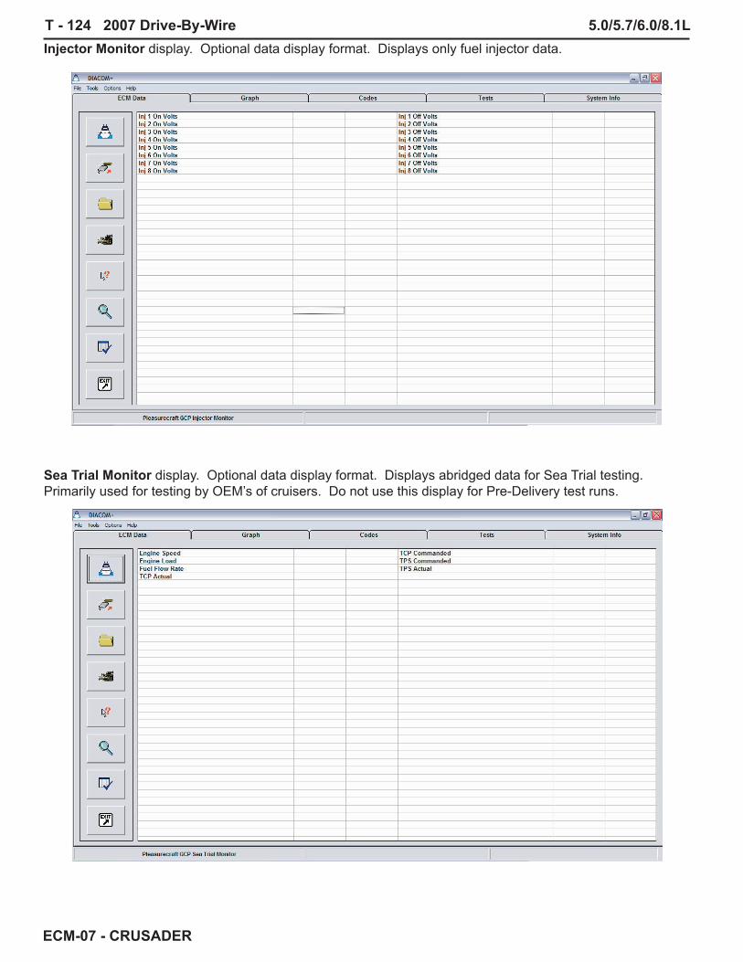
T - 124 2007 Drive-By-Wire 5.0/5.7/6.0/8.1L
ECM-07 - CRUSADER
Injector Monitor display. Optional data display format. Displays only fuel injector data.
Sea Trial Monitor display. Optional data display format. Displays abridged data for Sea Trial testing. Primarily used for testing by OEM’s of cruisers. Do not use this display for Pre-Delivery test runs.

5.0/5.7/6.0/8.1L 2007 Drive-By-Wire T - 125
ECM-07 - CRUSADER
Warning Monitor display. Optional data display format. Displays data associated with warning monitor functions.
Throttle Monitor display. Optional data display format. Displays data associated with throttle functions.

T - 126 2007 Drive-By-Wire 5.0/5.7/6.0/8.1L
ECM-07 - CRUSADER
Fuel Control Monitor display. Optional data display format. Displays fuel function related data.
GETTING LINKEDOnce you have selected your data set to display, Ensure the Diacom cable is connected to the DLC on the engine and, at a minimum, you have the engine set for Key ON Engine OFF operation. The KEY must be ON (engine running or off) for Diacom to link to the ECM.

5.0/5.7/6.0/8.1L 2007 Drive-By-Wire T - 127
ECM-07 - CRUSADER
SYSTEM INFO This is a new tab on the Diacom display for ECM-07. When this tab is selected you will get a screen containing all pertinent ECM information which includes: what engine the ECM is for, fi ring order, checksum, calibration fi le name, etc.
TESTSFor ECM-07, Diacom has a new set of tests that may be performed. When you select the Tests tab on the Diacom display, the Tests menu will open. When the menu opens you will get the Diacom message informing you that Diacom is going to break the Link with the ECM to proceed. If you wish to continue with the test function select YES, if you wish to return to the ECM display select NO.

T - 128 2007 Drive-By-Wire 5.0/5.7/6.0/8.1L
ECM-07 - CRUSADER
SPARK KILL TESTThis test and the Injector Kill Test are similar to the MEFI Power Balance Test. New with ECM-07 is the sequential fi re of a cylinder. Only one cylinder is fueled at a time and only one cylinder is fi red at a time. For the Spark Kill Test you will command the ECM to turn off the spark to a specifi ed cylinder. If the cylinder is functioning normally you will see a reduction in RPM when the cylinder is turned OFF.

5.0/5.7/6.0/8.1L 2007 Drive-By-Wire T - 129
ECM-07 - CRUSADER
When spark is turned OFF, you should see a reduction in RPM. The spark will remain off 2-4 seconds then resume normal operation.
SPARK FIRE TESTThis test will test fi re individual coils for the 6.0/81L engines. It is highly recommended that this test not be used. The 5.0/5.7L engines will fi re the coil, without proper indexing of the distributor there is no way to predict which plug will fi re. Engine damage, Fire or Explosion could occur during this test..

T - 130 2007 Drive-By-Wire 5.0/5.7/6.0/8.1L
ECM-07 - CRUSADER
Spark Fire Test screen.
RELAY TESTThis test will energize the Ignition Relay or the Ignition and Fuel Pump Relays. This test is extremely useful for troubleshooting power problems or for priming the fuel system. New with the ECM-07 controller is the fact that the Ignition and Fuel Pump relays will time out after 2-4 seconds with the Key ON Engine OFF.

5.0/5.7/6.0/8.1L 2007 Drive-By-Wire T - 131
ECM-07 - CRUSADER
RELAY TEST SCREEN
IDLE SPEED TESTThis test should be run with the engine idling, in neutral and at normal operating temperature. This test allows the idle speed to be varied in the range of 600 to 2000 RPM.

T - 132 2007 Drive-By-Wire 5.0/5.7/6.0/8.1L
ECM-07 - CRUSADER
IDLE SPEED TEST SCREEN
INJECTOR KILL TESTThis test and the Spark Kill Test are similar to the MEFI Power Balance Test. New with ECM-07 is the sequential fi re of a cylinder. Only one cylinder is fueled at a time and only one cylinder is fi red at a time. For the Injector Kill Test you will command the ECM to turn off the fuel to a specifi ed cylinder. If the cylinder is functioning normally you will see a reduction in RPM when the cylinder is turned OFF.

5.0/5.7/6.0/8.1L 2007 Drive-By-Wire T - 133
ECM-07 - CRUSADER
INJECTOR KILL TEST SCREEN
INJECTOR FIRE TESTThis test will fi re individual injectors. The test is performed with the Key ON Engine OFF. Be sure to observe all warnings associated with this test. The engine should be run for at least 5 minutes after fi ring an injector to clear out the unburned fuel. Extreme care must be taken to prevent hydrostatically locking a cylinder with fuel by performing this test

T - 134 2007 Drive-By-Wire 5.0/5.7/6.0/8.1L
ECM-07 - CRUSADER
INJECTOR FIRE TEST SCREEN
COMPRESSION TEST MODEWhen selected this test will disable spark and fuel to the engine so a cylinder compression test may be performed.

5.0/5.7/6.0/8.1L 2007 Drive-By-Wire T - 135
ECM-07 - CRUSADER
COMPRESSION TEST MODE SCREEN
DRIVE-BY-WIRE TEST (ETC ONLY)This test allows you to verify throttle body operation in the Key ON Engine OFF mode. Under normal operating conditions, the throttle plate will not move with throttle handle movement in the Key On Engine OFF mode, throttle plate movement is restricted to Engine Running mode only.

T - 136 2007 Drive-By-Wire 5.0/5.7/6.0/8.1L
ECM-07 - CRUSADER
DRIVE-BY-WIRE TEST (ETC ONLY) SCREEN
ACTIVE FAULT ECM DATA SCREENA fault has occurred and the ECM-07 has stored a DTC and lit the MIL.

5.0/5.7/6.0/8.1L 2007 Drive-By-Wire T - 137
ECM-07 - CRUSADER
ACTIVE FAULT CODES SCREENWhen a fault occurs, you must open the Codes screen to see what the fault is. Upon entering the Codes screen you must left click the Read Faults icon to view the diagnostic message..
IN-ACTIVE FAULT ECM DATA SCREENA fault occurred and the ECM-07 has stored a DTC. Note that if the fault is not active the MIL will not be lit. Diacom does display the Trouble Codes Found fl ag indicating a fault is stored in the ECM memory.

T - 138 2007 Drive-By-Wire 5.0/5.7/6.0/8.1L
ECM-07 - CRUSADER
IN-ACTIVE FAULT CODES SCREENWhen a fault occurs, you must open the Codes screen to see what the fault is. Upon entering the Codes screen you must left click the Read Faults icon to view the diagnostic message.
CLEAR FAULT CODES SCREENTo clear DTC(s) you must left click on the Pencil icon then select YES to clear the codes. Inactive codes may be cleared, if a fault is currently active the code will return even after clearing. You must turn the Ignition OFF to complete the clear codes cycle.

5.0/5.7/6.0/8.1L 2007 Drive-By-Wire T - 139
ECM-07 - CRUSADER
PEG ECM-07 - PREFERRED SCREEN
The following pages provide a sample of using the calibration download feature in the Diacom program. The sample shown is for a MEFI 4B calibration download. An ECM-07 download would follow a similar process. As you can see in the sample provided, Diacom will prompt you each step of the way. When performing an ECM-07 download, you will connect Diacom through the Diacom CAN Network Adapter to the CAN Network adapter on the engine harness (located next to the DLC connector). It is important to note that you should always ensure that the battery is charged on your laptop prior to beginning a calibration download. An ECM-07 download can take as long as 6-8 minutes to execute properly.

T - 140 2007 Drive-By-Wire 5.0/5.7/6.0/8.1L
ECM-07 - CRUSADER
Copying Database and Calibration Files to Hard Drive
This form facilitates the copying of files from a disk to a selected calibration folder on your hard drive. The new algorithm in this form will open the selected database file prior to being transferred and retrieve all the references to the calibration files. Once that information is obtained, it will search the entire location for those calibration files and transfer them together with the database file into the newly selected folder. If a referenced file is not found, a message box will be displayed informing you of the missing file name.
To copy a new calibration set from one location to another, perform the following steps:
1. Open the Diacom Program. 2. Insert CD into your CD drive. 3. Select Tools, and then select Load Calibration From Disk.
4. Select the Drive of the disk where the source calibration set resides (this can be the CD drive on your computer).
5. Select the source Folder where the calibration set resides, if there is one. 6. In the Available Calibration Sets box, select the CAN BUS Powerview
Kits.mdb database file. Please notice that this box will only display the database files (the files with the extension MDB) however, it will be your responsibility to copy all the related calibration files (with the CAL extension) in the same folder in order for the algorithm in the form to be able to find and copy those files together with the database file into the new destination folder.
7. Select the Destination drive. 8. Select the Destination folder. This can be any folder on your computer, but it is
recommended that you select a drive where the Diacom program is located

5.0/5.7/6.0/8.1L 2007 Drive-By-Wire T - 141
ECM-07 - CRUSADER
(preferably under the default Cal\Crusader directory created by default by Diacom installation program).
9. Click and hold the left mouse button on the Source Database File and drag the mouse cursor over to the destination file box on the right. If no messages appear, then the copy process ended successfully, otherwise the popup messages will display which calibration files could not be found in the folder where the calibration database files resides. To remedy this situation, please make sure that all calibration files (CAL extension) referenced in the calibration database file (MDB extension) can be found in the same folder. You can also select a source file and press the left mouse button to copy the new database to the destination folder.
Downloading a New Calibration
To download a new calibration into an ECM, follow the steps below:
1. In the Diacom Tools menu, select Download Calibration menu to activate the dialog box below.

T - 142 2007 Drive-By-Wire 5.0/5.7/6.0/8.1L
ECM-07 - CRUSADER
2. Select Load New Database.

5.0/5.7/6.0/8.1L 2007 Drive-By-Wire T - 143
ECM-07 - CRUSADER
3. Select the database file CAN BUS Powerview Kits.
4. From the displayed list of File Descriptions, select the appropriate calibration to download.
5. Press the Download Calibration button to start the download process. 6. After the completion of the download, you are instructed to turn the ignition OFF
for 5 seconds in order for the new calibration to be written to the ECM’s internal memory.