Crossfire X300 Owners Manual
171
OWNER’S/OPERATOR’S MANUAL X300 WARNING:Read this Manual , and any Supplements Carefully Before Operating Vehicle. Assembly Operation Maintenance This ATV should not be ridden by anyone under 16 years of age. BEFORE OPERATING THIS VEHICLE, THE OWNER AND EACH OPERATOR MUST HAVE READ AND HAVE AN UNDERSTANDING OF ALL THE INSTRUCTIONS FOR PROPER ASSEMBLY AND SAFE OPERATION OF THIS ATV. READING THIS MANUAL HELPS IN SAFE OPERTAION AND UPKEEP.
Transcript of Crossfire X300 Owners Manual
OWNER’S/OPERATOR’S
MANUAL
X300
WARNING:Read
this Manual , and
any Supplements
Carefully
Before Operating
Vehicle.
Assembly
Operation
Maintenance
This ATV
should not be
ridden by
anyone under
16 years of age.
BEFORE OPERATING THIS VEHICLE, THE OWNER AND EACH
OPERATOR MUST HAVE READ AND HAVE AN UNDERSTANDING OF
ALL THE INSTRUCTIONS FOR PROPER ASSEMBLY AND SAFE
OPERATION OF THIS ATV. READING THIS MANUAL HELPS IN SAFE
OPERTAION AND UPKEEP.
CONTENTS
1. INTRODUCTION
2. UNDERSTANDING WARNING
3. SAFETY WARNING
4. DAILY PRE-RIDE INSPECTION
5. OPERATION WARNING
6. V.I.N
7. CONTROL AND PARTS FUNCTIONS
8. STARTING THE ENGINE
9. VEHICLE BREAK-IN PERIOD
10. RIDING GEAR
11. CARRYING LOADS
12.Operating procedure
13. CVT SYSTEM
14. BATTERY
15. EXHAUST SYSTEM
16. MAINTENANCE

17. TROUBLE SHOOTING
18. TOOLS
19. SPECIFICATION
20. WIRING DIAGRAM
NOTE:
A storage area/toolbox has been provided under the seat of the ATV for
storage of this manual, and tool kit.
Please keep this manual and tool kit in the storage area/toolbox so that it
can be found easily and referenced when needed.
1. Introduction
Congratulations on the purchase of your ALL Terrain Vehicle
(ATV). We take pride in offering you this product engineered and
manufactured to the highest performance and quality standards.
We are sure that you will enjoy superior levels of performance,
reliability, riding comfort, and safety.
This manual is provided to help the owner and operators of this
ATV become familiar with the operating characteristic, and the
many features offered on the ATV. The manual also covers
information on the care and maintenance of your ATV.
Please read this manual carefully. The information contained in
this Owner’s Manual, the Warning Labels supplied with this
product will help you to understand the safe use and maintenance
of your ATV. Make sure that you understand and follow all
Warnings and Instructions in this material.
If you did not receive any of the material listed above, please call
your dealer and request to have them sent to you.
Important Safety Notice
Never make any modifications to the engine, drive system,
mechanical or electrical systems of your ATV. Never install
aftermarket parts or accessories intended to increase the speed
or power of your ATV.
Failure to follow these warnings increases the possibility of
accidents leading to DEATH or SERIOUS INJURY!
Additionally, failure to follow these requirements will void the
Warranty on your ATV.
NOTE
The addition and use of certain accessories including, (but not
limited to) mowers, blades, sprayers, winches and windshields will
change the handling characteristics and the performance of your
ATV.
Practice Responsible ATV Riding
Make sure that you understand and follow all local, state/province,
and federal/national riding laws and requirements.
Remember……Respect your vehicle, respect the environment
and respect the property of others. You are responsible for your
safety and the safety of others around you when you ride!
ATVs CAN BE HAZARDOUS TO OPERATE.
An ATV handles differently from other vehicles including
motorcycles and cars. A collision rollover can occur quickly, even
during routine maneuvers such as turning and driving on hills or
over obstacles, if you fail to take proper precautions.
SERIOUS INJURY OR DEATH can result if
you do not follow these instructions.
Read this manual and all labels carefully and follow the
operating procedures described.
Never operate an ATV without proper instruction. Take a
training course. Beginners should receive training from a
certified instructor. Contact an authorized ATV dealer to find
out about the training courses nearest you.
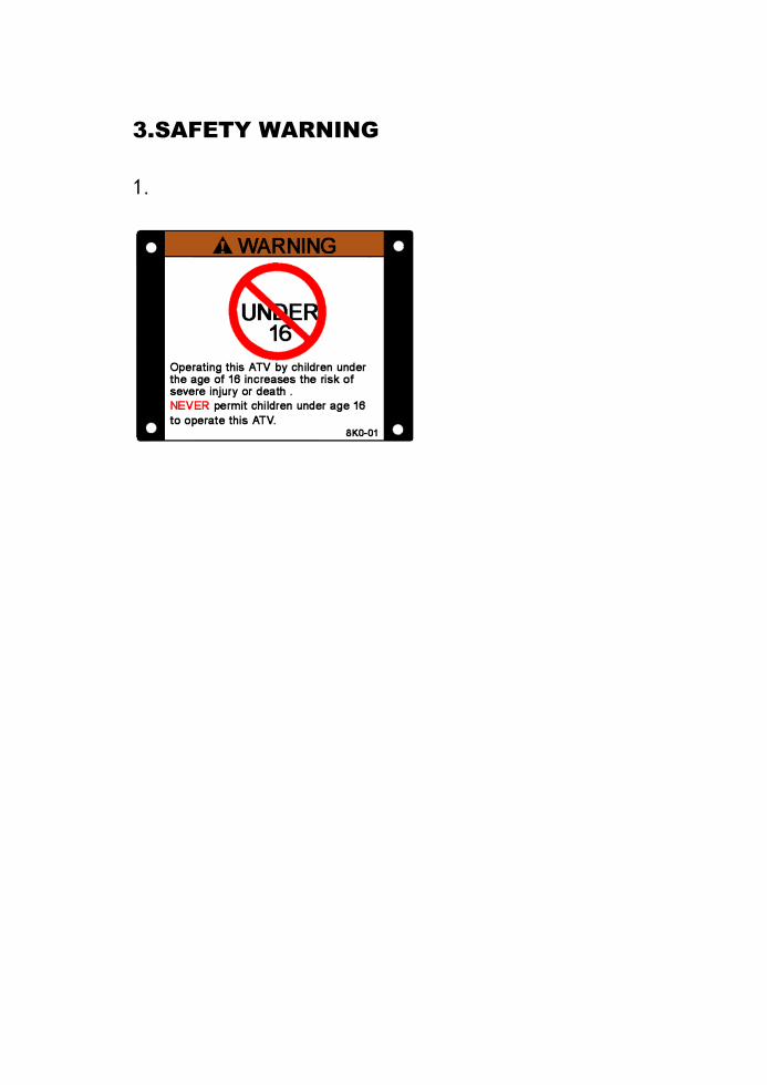
Never allow anyone who is not an 16 years of age to operate
this ATV.
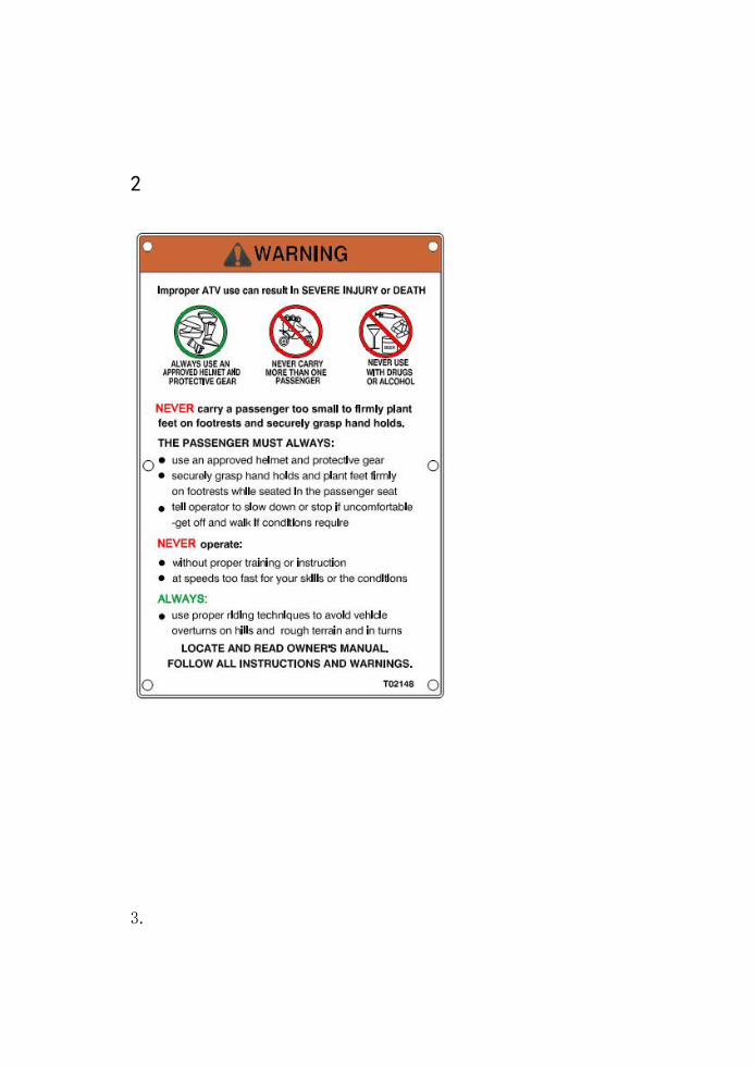
Never permit a guest to operate this ATV unless the guest has
read this manual and all product labels, and has completed a
certified training course.
Never operate an ATV without wearing an approved helmet
that fits properly. You should also wear eye protection
(goggles or face shield), gloves, boots, long-sleeved shirt or
jacket, and long pants.
Never consume alcohol or drugs before or while operating this
ATV.
Never operate at excessive speeds. Always travel at a speed
which is proper for the terrain, visibility and operating
conditions, and your experience.
Never attempt wheelies, jumps or other stunts.
Always inspect your ATV each time you use it to make sure it
is in safe operating condition. Always follow the inspection
and maintenance procedures and schedules described in this
manual.
Always keep both hands on the handlebars and both feet on
the footrests of the ATV during operation.
Always go slowly and be extra careful when operating on
unfamiliar terrain. Always be alert to changing terrain
conditions when operating the ATV.
Never operate on excessively rough, slippery or loose terrain.
Always follow proper procedures for turning as described in
this manual. Practice turning at low speeds before attempting
to turn at faster speeds. Do not turn at excessive speed.
Always have the ATV checked by an authorized dealer if it has
been involved in an accident.
Never operate ATV on hills too steep for the ATV or for your
abilities. Practice on smaller hills before attempting larger hills.
Always follow proper procedures for climbing hills as
described in this manual. Check the terrain carefully before
you start up any hill. Never climb hills with excessively slippery
or loose surfaces. Shift your weight forward. Never open
throttle suddenly or make sudden gear changes. Never go
over the top of any hill at high speed.
Always follow proper procedures for going down hills and for
braking on hills as described in this manual. Check the terrain
carefully before you start down any hill. Shift your weight
backward. Never go down a hill at high speed. Avoid going
down a hill at an angle which would cause the vehicle to lean
sharply to one side. Go straight down the hill where possible.
Always follow proper procedures for crossing the side of a hill
as described in this manual. Avoid hills with excessively
slippery or loose surfaces. Shift your weight to the uphill side
of the ATV. Never attempt to turn the ATV around on any hill
until you have mastered the turning technique described in
this manual on level ground. Avoid crossing the side of a steep
hill if possible.
Always use proper procedures if you stall or roll backwards
when climbing a hill. To avoid stalling, maintain a steady
speed when climbing a hill. If you stall or roll backwards, follow
the special procedure for braking described in this manual.
Dismount on the uphill side or to either side if pointed straight
uphill. Turn the ATV around and remount, following the
procedure described in this manual.
Always check for obstacles before operating in a new area.
Never attempt to operate over large obstacles, such as large
rocks or fallen trees. Always follow proper procedures when
operating over obstacles as described in this manual.
Always be careful of skidding of sliding. On slippery surfaces,
such as ice, go slowly and be very cautious in order to reduce
the chance of skidding or sliding out of control.
Avoid operating the ATV through deep or fast flowing water.
Avoid water which exceeds the recommended maximum
depth. Go slowly, balance your weight carefully avoiding
sudden movements, maintain a slow and steady forward
motion, do not make sudden turns or stops, and do not make
sudden throttle changes.
Wet brakes may have reduced stopping ability. Test your
brakes after leaving water. If necessary apply them lightly
several times to let friction dry out the pads.
Always be sure there are no obstacles or people behind you
when you operate in reverse. When it is safe to proceed in
reverse, go slowly. Avoid turning at sharp angles in reverse.
Always use the size and type tires specified in this manual.
Always maintain proper tire pressure as described in this
manual.
Never modify an ATV through improper installation or use of
accessories
Never exceed the stated load capacity for an ATV. Cargo
should be properly distributed and securely attached. Reduce
speed and follow instructions in this manual for carrying cargo
or pulling a trailer. Allow greater distance for braking.
2. UNDERSTANDING WARNINGS
ATTENTION:
This is an 16+ age VEHICLE ONLY: not a toy. READ AND
UNDERSTAND WARNINGS AND OWNER’S MANUAL BERORE
OPERATION.
KNOW YOUR VEHICLE BEFORE YOU BEGIN RIDING!
Read this manual thoroughly referring to the various areas which
are being discussed on your machine. Operating this vehicle
carries with it responsibilities for your personal safety, the safety
of others, and the protection of our environment.
NOTE: Illustrations used in this manual are for general
representation only. Your model may differ.
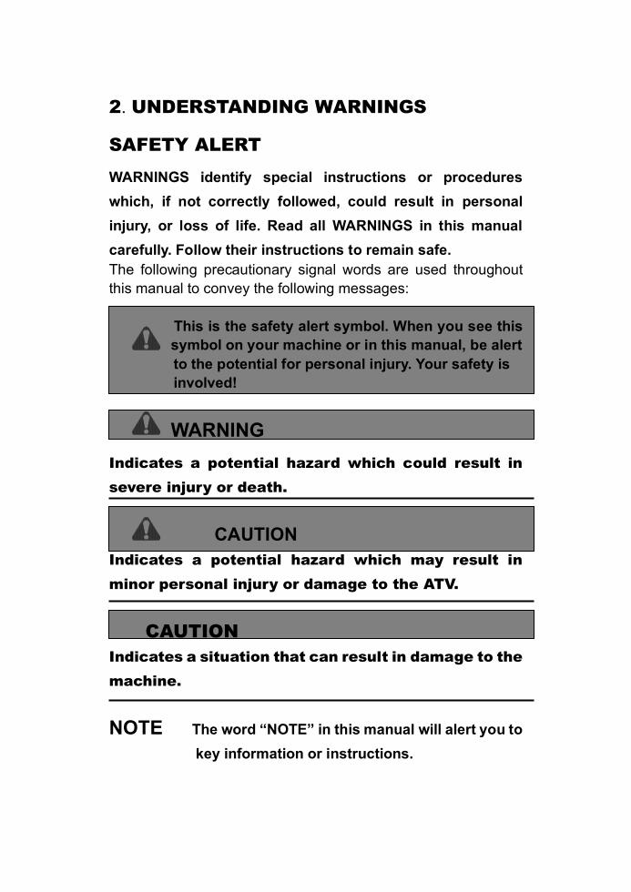
2. UNDERSTANDING WARNINGS
SAFETY ALERT
WARNINGS identify special instructions or procedures
which, if not correctly followed, could result in personal
injury, or loss of life. Read all WARNINGS in this manual
carefully. Follow their instructions to remain safe.
The following precautionary signal words are used throughout
this manual to convey the following messages:
This is the safety alert symbol. When you see this
symbol on your machine or in this manual, be alert
to the potential for personal injury. Your safety is
involved!
WARNING
Indicates a potential hazard which could result in
severe injury or death.
CAUTION
Indicates a potential hazard which may result in
minor personal injury or damage to the ATV.
CAUTION
Indicates a situation that can result in damage to the
machine.
NOTE The word “NOTE” in this manual will alert you to
key information or instructions.
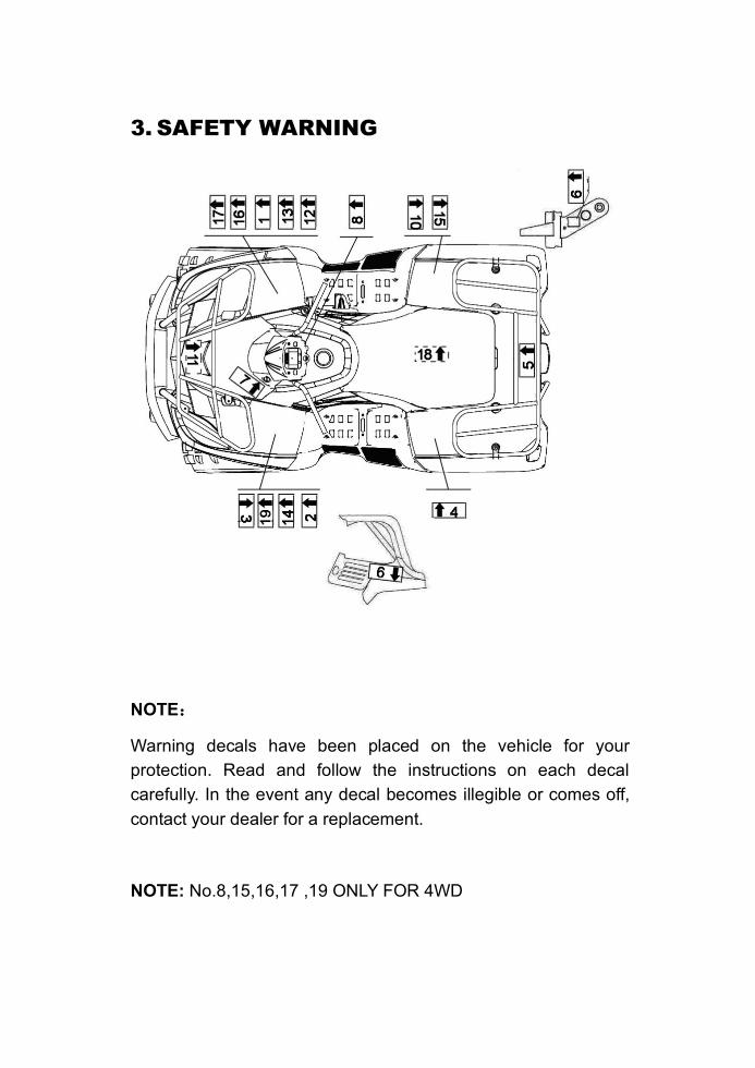
3. SAFETY WARNING
NOTE:
Warning decals have been placed on the vehicle for your
protection. Read and follow the instructions on each decal
carefully. In the event any decal becomes illegible or comes off,
contact your dealer for a replacement.
NOTE: No.8,15,16,17 ,19 ONLY FOR 4WD
3.SAFETY WARNING
1.
2
3.

4.
5.
6
7.
8. 9.
10.
11.
12.
13.
14
15

16.
17
18.
4
4. DAILY PRE-RIDE INSPECTION
WARNING
You must inspect your ATV each time before riding to ensure it is
in proper working order. If proper inspection is not done, severe
injury or death could result.
Use the following checklist to verify your machine is in proper
working order each time you ride.
Item/Inspection procedure
1. Tire-check condition and pressures.
2. Fuel tank-fill the fuel tank to its proper lever.
3. All brakes-check operation, adjustment and fluid level
(includes auxiliary brake).
4. Throttle-check for free operation and closing.
5. Headlight / Taillight / Brake light-check operation of all indicator
lights and switches.
6. Engine stop switch-check for proper function.
7. Wheels-check for tightness of wheel nuts and axle nuts; check
those axle nuts are secured by cotter pins.
8. Air cleaner element-check for dirt; clean or replace.

9. Steering-check for free operation noting any unusual
looseness in any area.
10. Loose parts-visually inspect vehicle for any damaged
components or loose nuts/bolts or fasteners.
11. Operators helmets, goggles and clothing.
12. Engine coolant check for proper level at the recovery bottle.
5. OPERATION WARNINGS
Get on and disembark ATV
Get on
Get on the ATV through left or right by steps.
Disembark
Check that the surroundings are in safe condition and then slowly
park the ATV.
Stop the engine. (Key off)
Push the parking lever to the ON position to lock the rear wheels.
Leave the ATV through left or right steps.
WARNING
POTENTIAL HAZARD
Operate this ATV without proper instruction.
WHAT CAN HAPPEN
The risk of an accident is greatly increased if operator does not
know how to operate the ATV properly in different situations and
on different types of terrain.
HOW TO AVOID THE HAZARD
Beginning and inexperienced operators should complete the
certified training course. They should then regularly techniques
described in the Owner’s Manual.
For more information about the training course, contact an
authorized ATV dealer.
WARNING
POTENTIAL HAZARD
Operate this ATV without wearing an approved helmet, eye
protection and protective clothing.
WHAT CAN HAPPEN
Operating without an approved helmet increases your chances of
a severe head injury or death in the event of an accident.
Operating without eye protection can result in an accident and
5. OPERATION WARNINGS
increases your chances of a severe injury in the event of an
accident.
HOW TO AVOID THE HAZARD
Always wear an approved helmet which fits properly.
You should also wear: eye protection (goggles or face shield);
gloves; boots; long-sleeved shirt or jacket; and long pants.
WARNING
POTENTIAL HAZARD
Operate this ATV after consuming alcohol or drugs.
WHAT CAN HAPPEN
Could seriously affect your judgment.
Could cause you to react more slowly.
Could affect your balance and perception.
Could result in an accident.
HOW TO AVOID THE HAZARD
Never consume alcohol or drugs before or while driving this ATV.
WARNING
POTENTIAL HAZARD
Operating this ATV at excessive speeds.
WHAT CAN HAPPEN
Increases your chances of losing control of the ATV, which can
result in an accident.
HOW TO AVOID THE HAZARD
Always travel at a speed which is proper for the terrain, visibility
and operating conditions; and your experience.
5. OPERATION WARNINGS
WARNING
POTENTIAL HAZARD
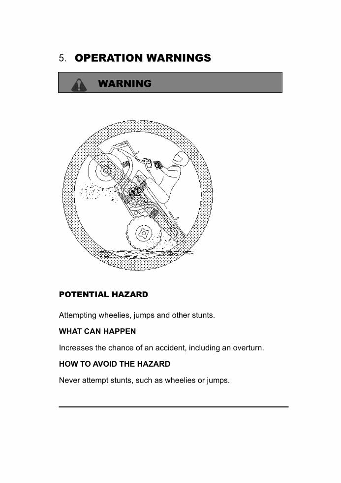
Attempting wheelies, jumps and other stunts.
WHAT CAN HAPPEN
Increases the chance of an accident, including an overturn.
HOW TO AVOID THE HAZARD
Never attempt stunts, such as wheelies or jumps.
5. OPERATION WARNINGS
WARNING
POTENTIAL HAZARD
Failure to inspect the ATV before operating.
Failure to properly maintain the ATV.
WHAT CAN HAPPEN
Increases the possibility of an accident or equipment damage.
HOW TO AVOID THE HAZARD
Always inspect your ATV each time you use it to make sure the
ATV is in safe operating condition.
Always follow the inspection and maintenance procedures and
schedules described in the Owner’s Manual.
WARNING
POTENTIAL HAZARD
Removing hands from handlebars or feet from footrests during
operation.
WHAT CAN HAPPEN

Removing even one hand or foot can reduce your ability to control
the ATV or could cause you to lose your balance and fall off the
ATV. If you remove a foot from the footrest, your foot or leg may
come into contact with the rear wheels. Which could injure you or
cause an accident.
HOW TO AVOID THE HAZARD
Always keep both hands on the handlebars and both feet on the
footrests of your ATV during operation.
5. OPERATION WARNINGS
WARNING
POTENTIAL HAZARD
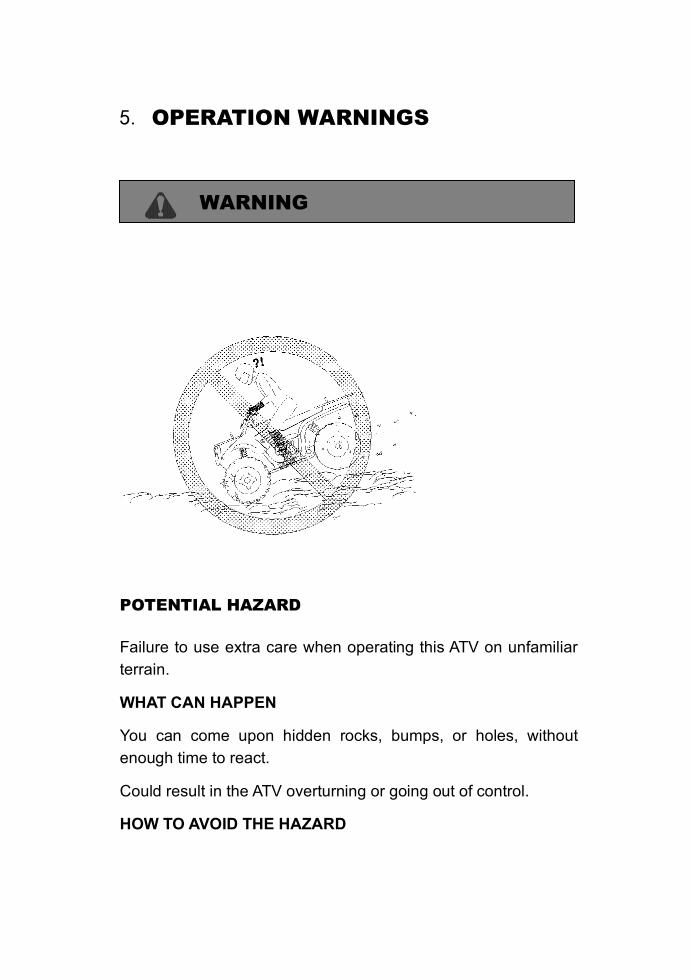
Failure to use extra care when operating this ATV on unfamiliar
terrain.
WHAT CAN HAPPEN
You can come upon hidden rocks, bumps, or holes, without
enough time to react.
Could result in the ATV overturning or going out of control.
HOW TO AVOID THE HAZARD
Go slowly and be extra careful when operating on unfamiliar
terrain.
Always be alert to changing terrain conditions when operating the
ATV.
5. OPERATION WARNINGS
WARNING
POTENTIAL HAZARD
Failure to use extra care when operating on excessively rough,
slippery or loose terrain.
WHAT CAN HAPPEN
Could cause loss of traction or vehicle control, which could result
in an accident, including an overturn.
HOW TO AVOID THE HAZARD
Do not operate on excessively rough, slippery or loose terrain until
you have learned and practiced the skills necessary to control the
ATV on such terrain.
Always be especially cautious on these kinds of terrain.
WARNING
POTENTIAL HAZARD
Climbing hills improperly.
WHAT CAN HAPPEN
Could cause loss of control or cause ATV to overturn.
HOW TO AVOID THE HAZARD
Always follow proper procedures for climbing hills as described in
the Owner’s Manual.
Always check the terrain carefully before you start up any hill.
Never climb hills with excessively slippery or loose surfaces.
Shift your weight forward.
Never open the throttle suddenly. The ATV could flip over
backwards.
Never go over the top of any hill at high speed. An obstacle, a
sharp drop, or another vehicle or person could be on the other
side of the hill.
5. OPERATION WARNINGS
WARNING
POTENTIAL HAZARD
Turning improperly.
WHAT CAN HAPPEN
ATV could go out of control, causing a collision or overturn.
HOW TO AVOID THE HAZARD
Always follow proper procedures for turning as described in the
Owner’s Manual.
Practice turning at low speeds before attempting to turn at faster
speeds.
Do not turn at excessive speed.
WARNING
POTENTIAL HAZARD
Operating on excessively steep hills.
WHAT CAN HAPPEN
The vehicle can overturn more easily on extremely steep hills than
on level surfaces or small hills.
HOW TO AVOID THE HAZARD
Never operate the ATV on hills too steep for the ATV or for your
abilities.
Practice on smaller hills before attempting large hills.
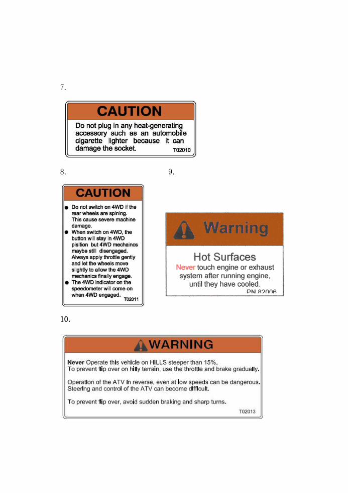
Never operate ATV on hills steeper than 15%.
5. OPERATION WARNINGS
WARNING
POTENTIAL HAZARD
Going down a hill improperly.
WHAT CAN HAPPEN
Could cause loss of control or cause ATV to overturn.
HOW TO AVOID THE HAZARD
Always follow proper procedures for going down hills as described
in the Owner’s Manual. NOTE: A special technique is required
when braking as you go downhill.
Always check the terrain carefully before you start down any hill.
Shift your weight backward.
Never go down a hill at high speed.
Avoid going down a hill at an angle which would cause the vehicle
to lean sharply to one side. Go straight down the hill where
possible.
WARNING
POTENTIAL HAZARD
Improperly crossing hills or turning on hills.
WHAT CAN HAPPEN
Could cause loss of control or cause ATV to overturn.
HOW TO AVOID THE HAZARD
Never attempt to turn the ATV around on any hill until you have
mastered the turning technique as described in the Owner’s
Manual on level ground. Be very careful then turning on any hill.
Avoid crossing the side of a steep hill if possible.
When crossing the side of a hill:
Always follow proper procedures as described in the Owner’s
Manual.
Avoid hills with excessively slippery or loose surfaces.
Shift your weight to the uphill side of the ATV.
5. OPERATION WARNINGS
WARNING
POTENTIAL HAZARD
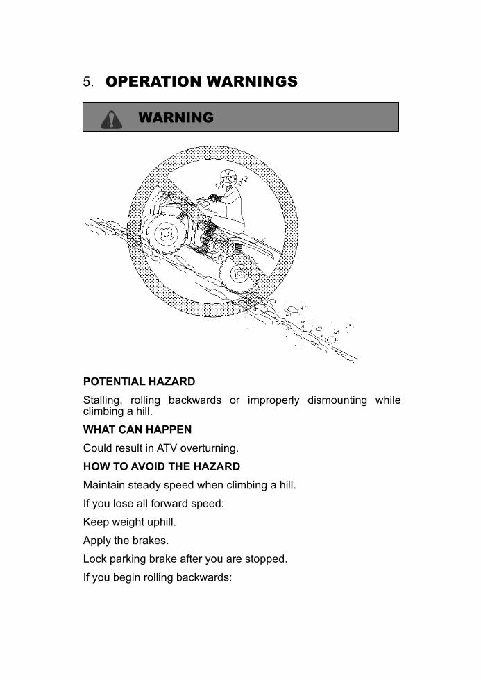
Stalling, rolling backwards or improperly dismounting while climbing a hill.
WHAT CAN HAPPEN
Could result in ATV overturning.
HOW TO AVOID THE HAZARD
Maintain steady speed when climbing a hill.
If you lose all forward speed:
Keep weight uphill.
Apply the brakes.
Lock parking brake after you are stopped.
If you begin rolling backwards:
Keep weight uphill; never apply engine power.
Never apply the rear brake while rolling backwards (150 and 200).
Apply the single-lever brake gradually.
When fully stopped, apply rear brake as well(150 and 200), and then lock parking brake.
Dismount on uphill side, or to either side if pointed straight uphill.
Turn the ATV around and remount following the procedure described in the Owner’s Manual.
5. OPERATION WARNINGS
WARNING
POTENTIAL HAZARD
Improperly operating over obstacles.
WHAT CAN HAPPEN
Could cause loss of control or a collision. Could cause the ATV to
overturn.
HOW TO AVOID THE HAZARD
Before operating in a new area, check for obstacles.
Use extreme caution when riding over large obstacles, such as
large rocks or fallen trees.
If you cannot avoid obstacles, always follow proper procedures as
described in the Owner’s Manual.
WARNING
POTENTIAL HAZARD
Skidding or sliding,
WHAT CAN HAPPEN
You may lose control of the ATV.
You may also regain traction unexpectedly, which may cause the
ATV to overturn.
HOW TO AVOID THE HAZARD
On slippery surfaces, such as ice, go slowly and be very cautious
in order to reduce the chance or skidding or sliding out of control.
5. OPERATION WARNINGS
WARNING
POTENTIAL HAZARD
Operating this ATV through deep or fast flowing water.
WHAT CAN HAPPEN
Tires may float, causing loss of traction and loss of control, which
could lead to an accident.
HOW TO AVOID THE HAZARD
Never operating the ATV through water which exceeds the
recommended maximum depth in this manual.
Avoid operating the ATV through deep or fast flowing water. If you
cannot avoid water, go slowly, balance your weight carefully
avoiding sudden movement, maintain a slow and steady forward
motion, do not make sudden turns or stops, and do not make
sudden throttle changes.
Remember that wet brakes may have reduced stopping ability.
Test your brakes after leaving water. If necessary, apply them
several times to let friction dry out the pads.
WARNING
POTENTIAL HAZARD
Improperly operating in reverse,
WHAT CAN HAPPEN
You could hit an obstacle or person behind you, resulting in severe
injury.
HOW TO AVOID THE HAZARD
When you select reverse gear, make sure there are no obstacles
or people behind you. When it is safe to proceed, go slowly.
5. OPERATION WARNINGS
WARNING
POTENTIAL HAZARD
Operating this ATV with improper tires, or with improper or uneven
tire pressure.
WHAT CAN HAPPEN
Use of improper tires on this ATV, or operation of this ATV with
improper or uneven tier pressure, may cause loss of control, and
increases the risk of an accident.
HOW TO AVOID THE HAZARD
Always use the size and type ties specified in the Owner’s Manual
for this vehicle.
Always maintain proper tire pressure a described in the Owner’s
Manual.
WARNING
POTENTIAL HAZARD
Operating this ATV with improper modifications.
WHAT CAN HAPPEN
Improper installation of accessories or modification of this vehicle
may cause changes in handling which in some situations could
lead to an accident.
HOW TO AVOID THE HAZARD
Never modify this ATV through improper installation or use of
accessories. All parts and accessories added to this vehicle
should be genuine or equivalent components designed for use on
this ATV; and should be installed and used according to
instructions. If you have questions, consult an authorized dealer.
5. OPERATION WARNINGS
WARNING
POTENTIAL HAZARD
Overloading this ATV or carrying or towing cargo improperly.
WHAT CAN HAPPEN
Could cause changes in vehicle handling which could lead to an
accident.
HOW TO AVOID THE HAZARD
Never exceed the stated load capacity for this ATV,
Cargo should be properly distributed and securely attached,
Reduce speed when carrying cargo or pulling a trailer.
Allow greater distance for braking.
Always follow the instructions in the Owner’s Manual for carrying
cargo or pulling a trailer.
WARNING
POTENTIAL HAZARD
Riding on frozen lakes and rivers.
WHAT CAN HAPPEN
Severe injury or death can result if the ATV and /or the operator
break through the ice.
HOW TO AVOID THE HAZARD
Never ride you ATV on a frozen body of water before you are sure
the ice is thick enough and sound enough to support the machine
and its operator, as well as the force that is created by a moving
vehicle.

5. OPERATION WARNINGS
WARNING
After a rollover or an accident, have a qualified service dealer
check the complete machine including, but not limited to, brakes,
throttle and steering for possible damage.
WARNING
Safe operation of this rider active vehicle requires good
judgement and physical skills. Persons with cognitive or physical
disabilities who operate this vehicle have an increased risk of
overturns and loss of control which could result in severe injury or
death.
CAUTION
Keep combustible materials away from exhaust system. Fire may
result.
6.V.I.N.
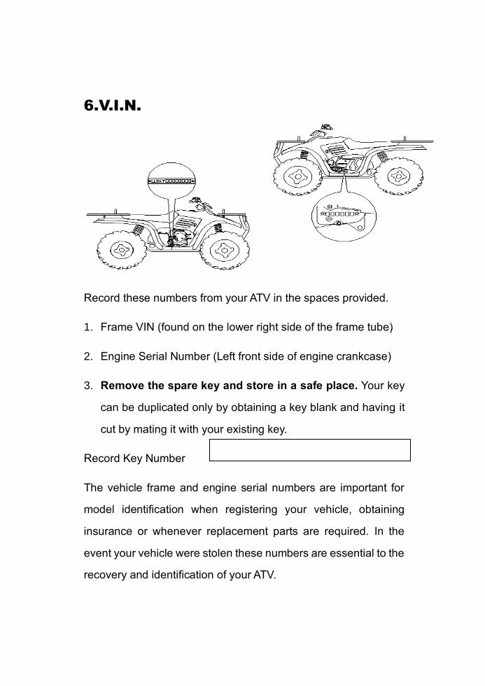
Record these numbers from your ATV in the spaces provided.
1. Frame VIN (found on the lower right side of the frame tube)
2. Engine Serial Number (Left front side of engine crankcase)
3. Remove the spare key and store in a safe place. Your key
can be duplicated only by obtaining a key blank and having it
cut by mating it with your existing key.
Record Key Number
The vehicle frame and engine serial numbers are important for
model identification when registering your vehicle, obtaining
insurance or whenever replacement parts are required. In the
event your vehicle were stolen these numbers are essential to the
recovery and identification of your ATV.
7. CONTROL AND PARTS FUNCTIONS
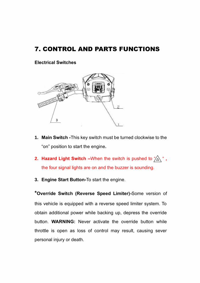
Electrical Switches
1. Main Switch -This key switch must be turned clockwise to the
“on” position to start the engine.
2. Hazard Light Switch –When the switch is pushed to “ “ ,
the four signal lights are on and the buzzer is sounding.
3. Engine Start Button-To start the engine.
*Override Switch (Reverse Speed Limiter)-Some version of
this vehicle is equipped with a reverse speed limiter system. To
obtain additional power while backing up, depress the override
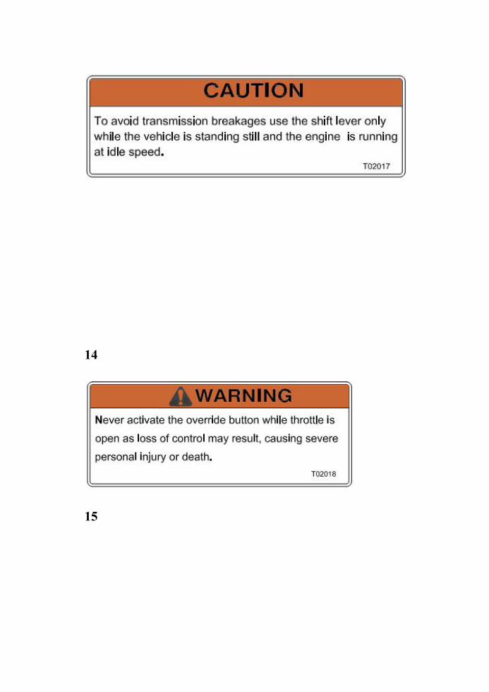
button. WARNING: Never activate the override button while
throttle is open as loss of control may result, causing sever
personal injury or death.

7. CONTROL AND PARTS FUNCTIONS
Insert the key into the key switch
A. “OFF” B.“ON” C.“HEAD LIGHT”
“OFF”: Turn the key to this position to stop the engine, switch
off all the electrical circuits and remove the key.
“ON”: In this position, the ATV electrical system is connected,
the engine can be started and the key cannot be removed.
“HEAD LIGHT”: In this position, the head light will be on.
WARNING
Never turn the key to “OFF” position when the ATV is in
motion. Otherwise the electrical system is shut off, which is
likely to result in losing control or having an accident. Always
make sure that the ATV is stopped before turning the key to
“OFF”position.
7. CONTROL AND PARTS FUNCTIONS
Light Switches and Indicator Lights
WARNING
Use caution and drive at reduced speeds in conditions of reduced
visibility such as fog, rain and darkness.
Switches
The light switch is located on the left hand handlebar. In addition
to turning the lights on and off, it also switches the lights from to
Lo on models equipped with Hi – Lo beams. NOTE: Will not light
unless the main switch is on.
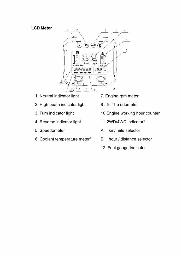
LCD Meter
1. Neutral indicator light 7. Engine rpm meter
2. High beam indicator light 8、9. The odometer
3. Turn indicator light 10.Engine working hour counter
4. Reverse indicator light 11. 2WD/4WD indicator*
5. Speedometer A: km/ mile selector
6. Coolant temperature meter* B: hour / distance selector
12. Fuel gauge Indicator
7. CONTROL AND PARTS FUNCTIONS
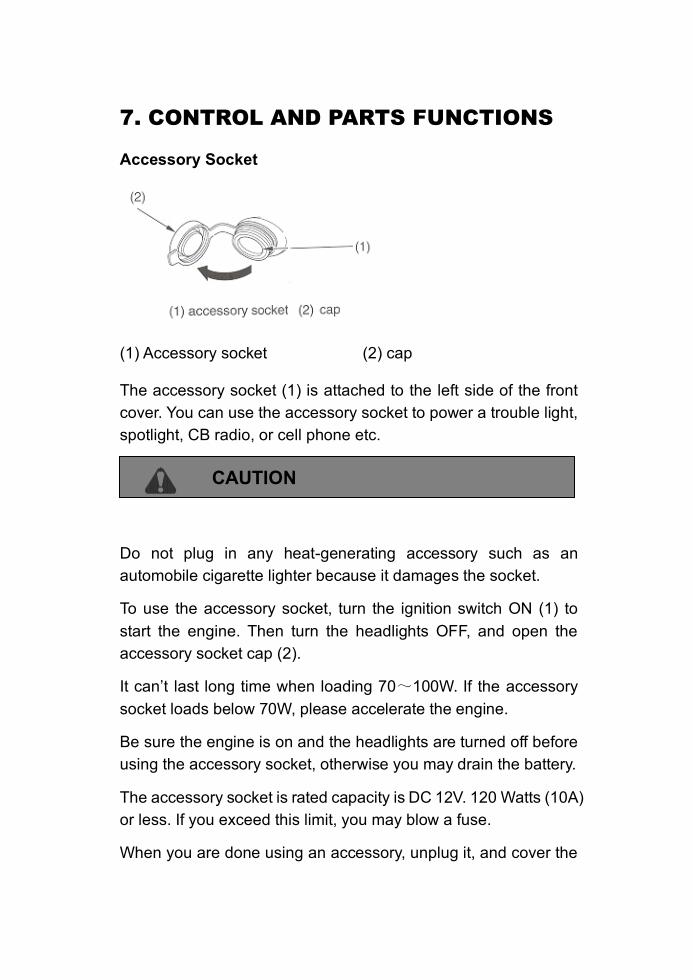
Accessory Socket
(1) Accessory socket (2) cap
The accessory socket (1) is attached to the left side of the front
cover. You can use the accessory socket to power a trouble light,
spotlight, CB radio, or cell phone etc.
CAUTION
Do not plug in any heat-generating accessory such as an
automobile cigarette lighter because it damages the socket.
To use the accessory socket, turn the ignition switch ON (1) to
start the engine. Then turn the headlights OFF, and open the
accessory socket cap (2).
It can’t last long time when loading 70~100W. If the accessory
socket loads below 70W, please accelerate the engine.
Be sure the engine is on and the headlights are turned off before
using the accessory socket, otherwise you may drain the battery.
The accessory socket is rated capacity is DC 12V. 120 Watts (10A)
or less. If you exceed this limit, you may blow a fuse.
When you are done using an accessory, unplug it, and cover the

socket with the cap.
Be careful not to flood this accessory socket when washing your
ATV.
7. CONTROL AND PARTS FUNCTIONS
Throttle
WARNING
Do not start or operate an ATV with sticking or improperly
operation throttle controls. A stuck or improperly operating throttle
could cause an accident resulting in severe injury or death.
Always contact your dealer for service repairs whenever throttle
problems arise.
Failure to check or maintain proper operation of the throttle
system can result in the throttle lever sticking during riding and
cause an accident.
Always check the lever for free movement and return before
starting the engine and occasionally during riding.
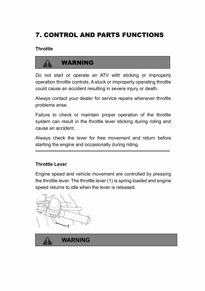
Throttle Lever Engine speed and vehicle movement are controlled by pressing
the throttle lever. The throttle lever (1) is spring loaded and engine
speed returns to idle when the lever is released.
WARNING
Washing or operating the scooter in freezing temperatures
can result in water freezing in the throttle cable conduit and/
or on the throttle mechanism.
This may result in the throttle sticking which can cause the engine
to continue to run and result in loss of control.
7. CONTROL AND PARTS FUNCTIONS
Front and Rear Brakes
The brake fluid level should be checked before each ride. The
reservoir of hand brake is located on the left side of the handlebar.
The reservoir of foot brake is located under the seat. The fluid
should be kept between the maximum and minimum marks.
CAUTION
Once a bottle of brake fluid is opened, use what is necessary and
discard the rest. Do not store or use a partial bottle of brake fluid.
Brake fluid is hygroscopic, meaning it rapidly absorbs moisture
from the air. This causes the boiling temperature of the brake fluid
to drop, which can lead to early brake fade and the possibility of
sever injury.
Front and Rear Brakes
The front and rear brakes are located on the inside of the right
floor board and are operated by the right foot. The front and rear
brakes are hydraulically activated disc type brakes which are
activated by one pedal only.
Always test brake pedal travel and reservoir fluid level before
riding. When squeezed, the pedal should feel firm. Any
sponginess would indicate a possible fluid leak or low master
cylinder fluid pedal which must be corrected before riding. Contact
your dealer for proper diagnosis and repairs.
7. CONTROL AND PARTS FUNCTIONS
WARNING
Never operate the ATV with a spongy feeling brake pedal.
operating the ATV with a spongy brake pedal can result in loss of
braking. Loss of braking could cause an accident.
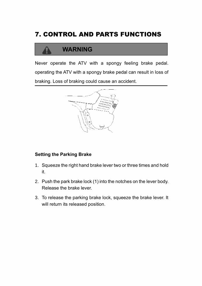
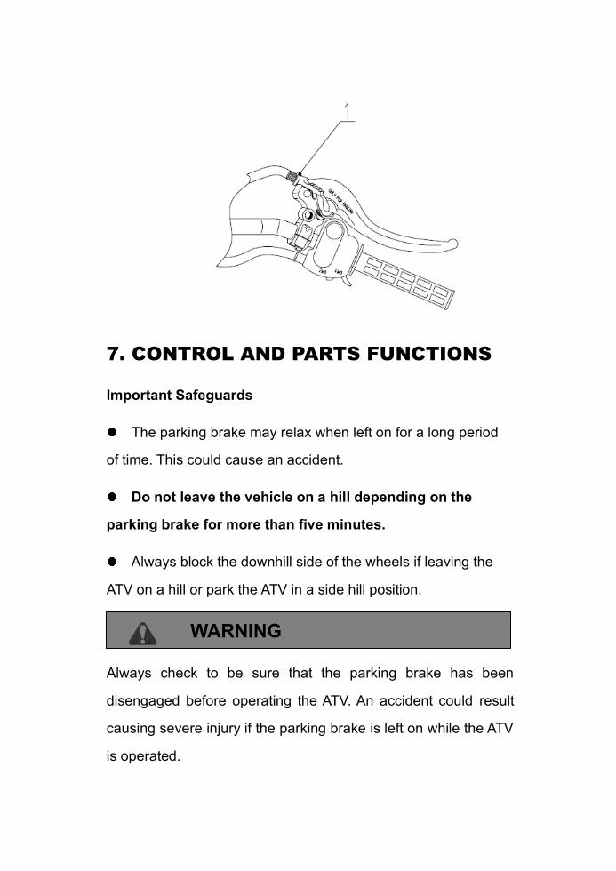
Setting the Parking Brake
1. Squeeze the right hand brake lever two or three times and hold
it.
2. Push the park brake lock (1) into the notches on the lever body.
Release the brake lever.
3. To release the parking brake lock, squeeze the brake lever. It
will return its released position.
7. CONTROL AND PARTS FUNCTIONS
Important Safeguards
The parking brake may relax when left on for a long period
of time. This could cause an accident.
Do not leave the vehicle on a hill depending on the
parking brake for more than five minutes.
Always block the downhill side of the wheels if leaving the
ATV on a hill or park the ATV in a side hill position.
WARNING
Always check to be sure that the parking brake has been
disengaged before operating the ATV. An accident could result
causing severe injury if the parking brake is left on while the ATV
is operated.

Auxiliary Brake
WARNING
Use caution when applying the auxiliary brake. Do not
aggressively apply the auxiliary brake when going forward or
the rear wheels may skid and slide sideways causing loss of
control.
Auxiliary brake lever
7. CONTROL AND PARTS FUNCTIONS
Your ATV has an auxiliary brake provided brake as a safety
feature. It is located on the left handlebar and is operated by the
left hand. It is intended as a backup to the main brake system,
especially if the main system becomes inoperative.
If the rear wheels slide, apply the rear brake with the left hand to
some extent. Aggressively applying the rear brake when backing
down a hill may cause rear tip over.
NOTE: On 300cc ATV, the auxiliary brake will be as effective as
the all wheel system.
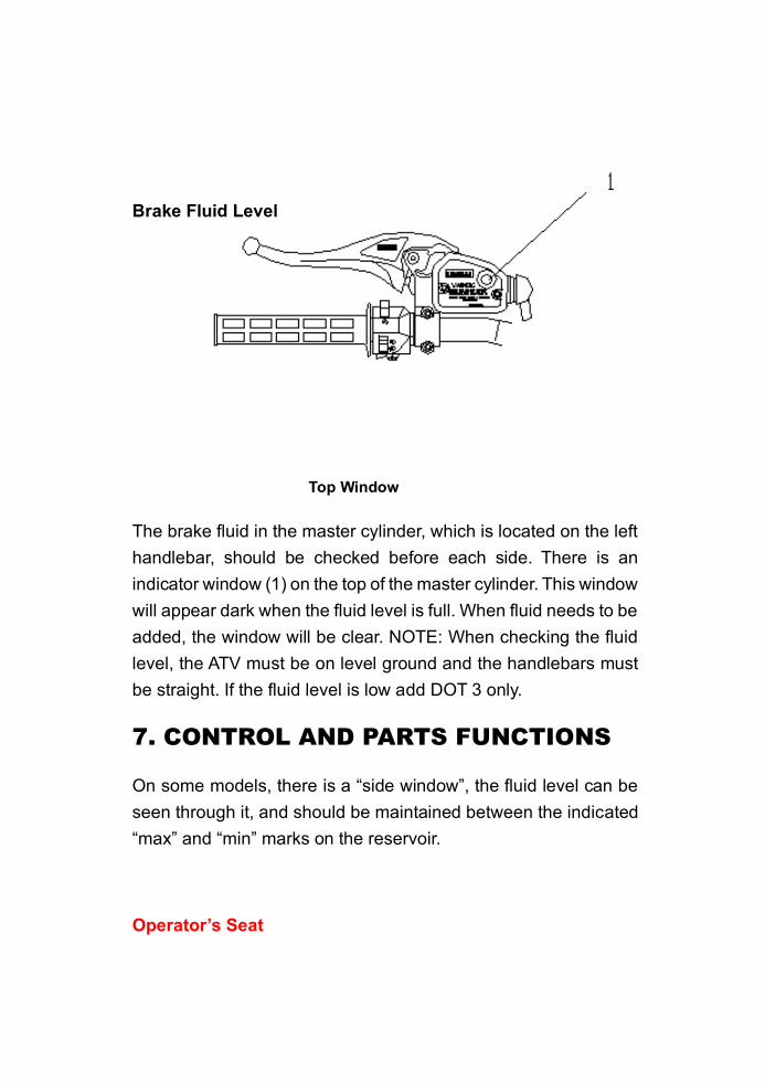
Brake Fluid Level
Top Window
The brake fluid in the master cylinder, which is located on the left
handlebar, should be checked before each side. There is an
indicator window (1) on the top of the master cylinder. This window
will appear dark when the fluid level is full. When fluid needs to be
added, the window will be clear. NOTE: When checking the fluid
level, the ATV must be on level ground and the handlebars must
be straight. If the fluid level is low add DOT 3 only.
7. CONTROL AND PARTS FUNCTIONS
On some models, there is a “side window”, the fluid level can be
seen through it, and should be maintained between the indicated
“max” and “min” marks on the reservoir.
Operator’s Seat
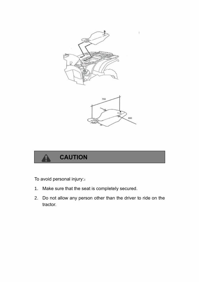
CAUTION
To avoid personal injury::
1. Make sure that the seat is compIeteIy secured.
2. Do not allow any person other than the driver to ride on the
tractor.
7. CONTROL AND PARTS FUNCTIONS
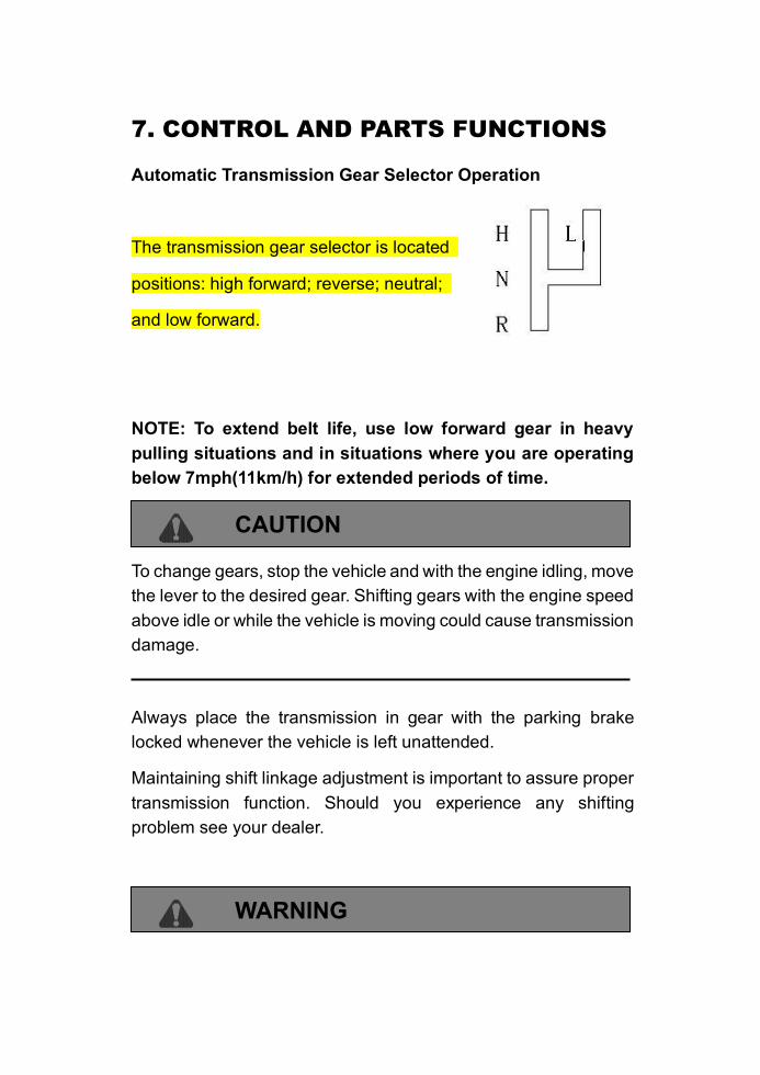
Automatic Transmission Gear Selector Operation
The transmission gear selector is located
positions: high forward; reverse; neutral;
and low forward.
NOTE: To extend belt life, use low forward gear in heavy
pulling situations and in situations where you are operating
below 7mph(11km/h) for extended periods of time.
CAUTION
To change gears, stop the vehicle and with the engine idling, move
the lever to the desired gear. Shifting gears with the engine speed
above idle or while the vehicle is moving could cause transmission
damage.
Always place the transmission in gear with the parking brake
locked whenever the vehicle is left unattended.
Maintaining shift linkage adjustment is important to assure proper
transmission function. Should you experience any shifting
problem see your dealer.
WARNING
POTENTIAL HAZARD (for 300cc)
Engaging a lower gear when the engine speed is too high.
WHAT CAN HAPPEN
The wheels could stop rotating. This could cause loss of control,
an accident and injury. It could also cause engine or drive train
damage.
HOW TO AVOID THE HAZARD
Make certain the engine has sufficiently slowed before shifting to
a lower gear.
7. CONTROL AND PARTS FUNCTIONS
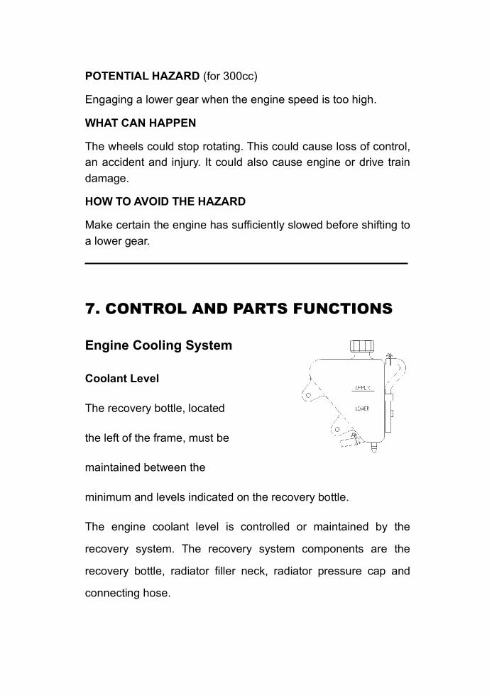
Engine Cooling System
Coolant Level
The recovery bottle, located
the left of the frame, must be
maintained between the
minimum and levels indicated on the recovery bottle.
The engine coolant level is controlled or maintained by the
recovery system. The recovery system components are the
recovery bottle, radiator filler neck, radiator pressure cap and
connecting hose.
As coolant operating temperature increases, the expanding
(heated) excess coolant is forced out of the radiator past the
pressure cap and into the recovery bottle. As engine coolant
temperature decreases, the contracting (cooled) coolant is drawn
back up from the tank past the pressure cap and into the radiator.
NOTE: Some coolant level drop on new machines is normal as
the system is purging itself of trapped air. Observe coolant levels
and maintain as recommended by adding coolant to the recovery
bottle. We recommends the use of a 50/50 mixture of high quality
aluminum compatible anti-freeze coolant and distilled water.
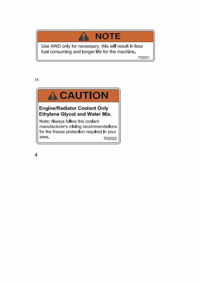
NOTE: Always follow the manufacturer’s mixing
recommendations for the freeze protection required in your area.
7. CONTROL AND PARTS FUNCTIONS
Cooling System
WARNING
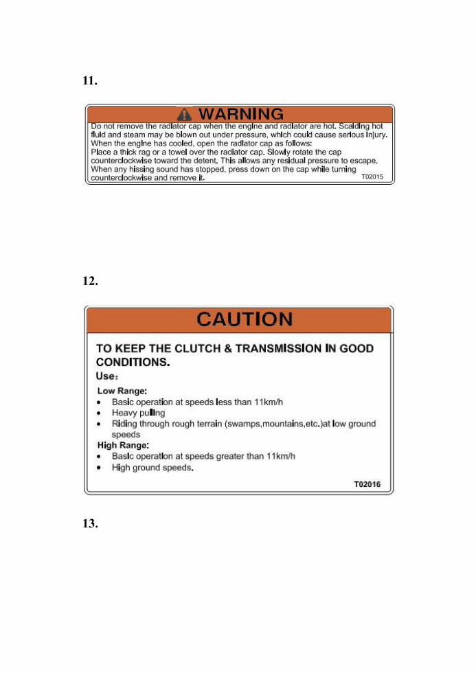
Never remove the pressure cap when the engine is warm or hot.
Escaping steam can cause severe burns. The engine must be
cool before removing the pressure cap.
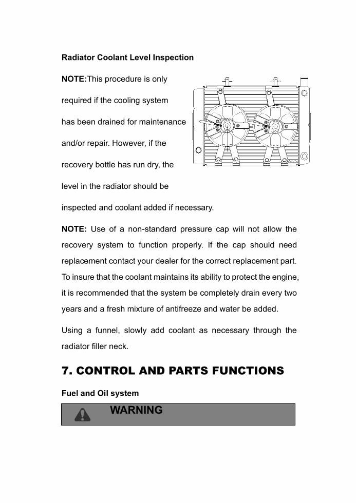
Radiator Coolant Level Inspection
NOTE:This procedure is only
required if the cooling system
has been drained for maintenance
and/or repair. However, if the
recovery bottle has run dry, the
level in the radiator should be
inspected and coolant added if necessary.
NOTE: Use of a non-standard pressure cap will not allow the
recovery system to function properly. If the cap should need
replacement contact your dealer for the correct replacement part.
To insure that the coolant maintains its ability to protect the engine,
it is recommended that the system be completely drain every two
years and a fresh mixture of antifreeze and water be added.
Using a funnel, slowly add coolant as necessary through the
radiator filler neck.
7. CONTROL AND PARTS FUNCTIONS
Fuel and Oil system
WARNING
Gasoline is highly flammable and explosive under certain
conditions.
Always exercise extreme caution whenever handling gasoline.
Always refuel with the engine stopped and outdoors or in a
well ventilated area.
Do not smoke or allow open flames or sparks in or near the
area where refueling is performed or where gasoline is stored.
Do not over fill the tank. Do not fill the tank neck.
If you get gasoline on your skin or clothing, immediately wash
it off with soap and water and change clothing.
Never start the engine or let it run in an enclosed area.
Gasoline powered engine exhaust fumes are poisonous and
can cause loss of consciousness and death in a short time.
Shut off fuel valve whenever the ATV is stored or parked.
WARNING
The engine exhaust from this product contains chemicals known,
in certain quantities, to cause cancer, birth defects or other
reproductive harm.
7. CONTROL AND PARTS FUNCTIONS
Fuel and Oil System
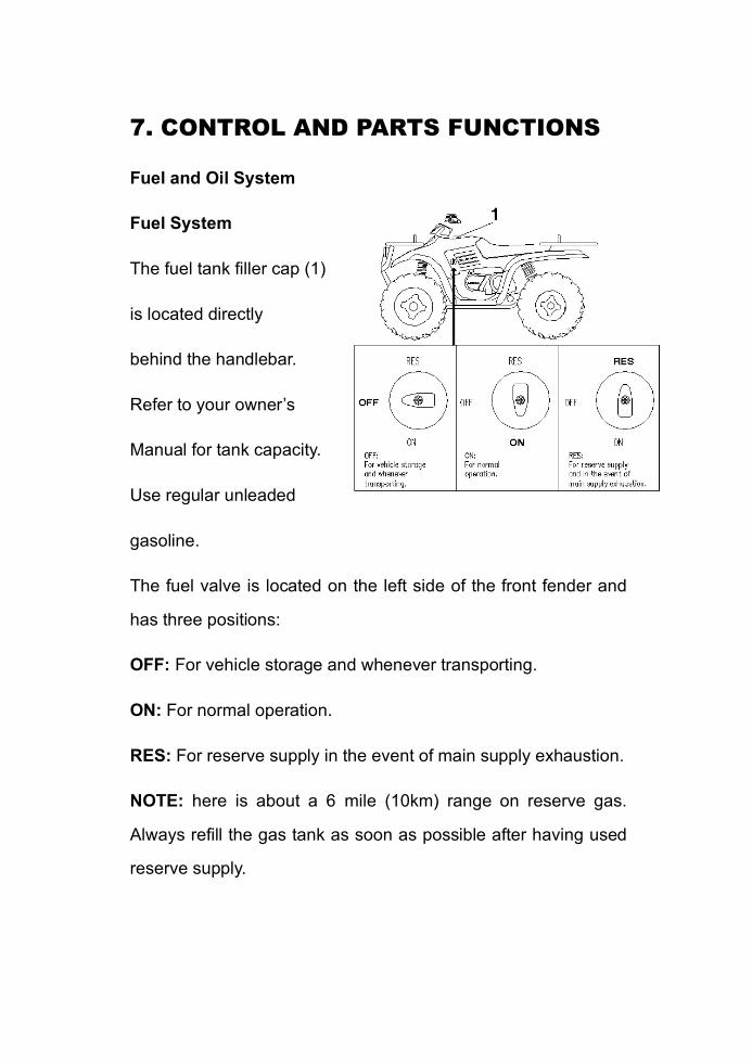
Fuel System
The fuel tank filler cap (1)
is located directly
behind the handlebar.
Refer to your owner’s
Manual for tank capacity.
Use regular unleaded
gasoline.
The fuel valve is located on the left side of the front fender and
has three positions:
OFF: For vehicle storage and whenever transporting.
ON: For normal operation.
RES: For reserve supply in the event of main supply exhaustion.
NOTE: here is about a 6 mile (10km) range on reserve gas.
Always refill the gas tank as soon as possible after having used
reserve supply.
Always return valve to “on “position after refueling machine.
Fuel filter
The filter should be replaced by your dealer every 100 hours of
operation or annually. Do not attempt to clean the fuel filter. The
filter is on the fuel valve in the tank.
7. CONTROL AND PARTS FUNCTIONS
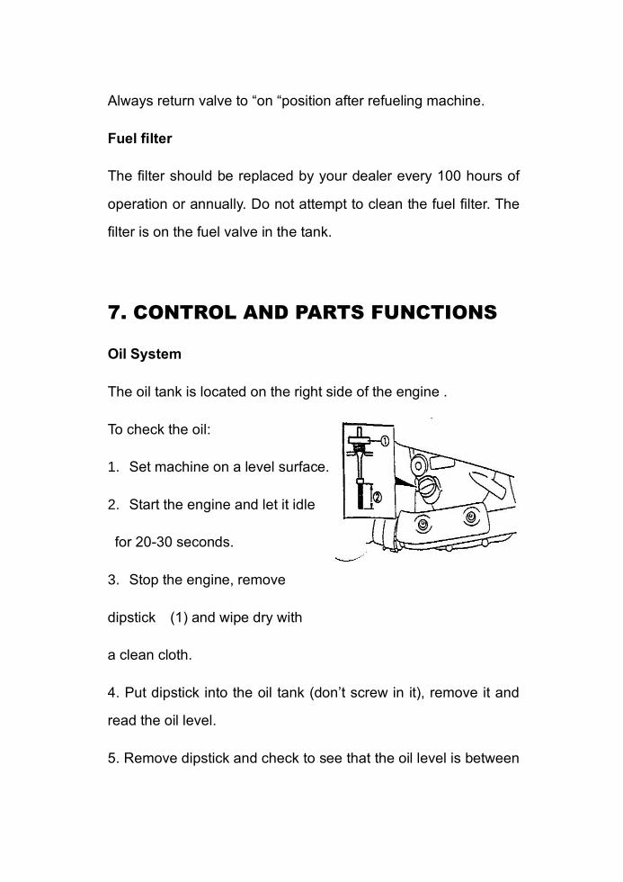
Oil System
The oil tank is located on the right side of the engine .
To check the oil:
1. Set machine on a level surface.
2. Start the engine and let it idle
for 20-30 seconds.
3. Stop the engine, remove
dipstick (1) and wipe dry with
a clean cloth.
4. Put dipstick into the oil tank (don’t screw in it), remove it and
read the oil level.
5. Remove dipstick and check to see that the oil level is between
the full and add marks(2). Add oil as indicated by the level on the
dipstick. Do not overfill.
CAUTION
Use only SAE 15W/40, SG OIL. Never substitute or mix oil brands.
Serious engine damage and voiding of warranty can result.
7. CONTROL AND PARTS FUNCTIONS
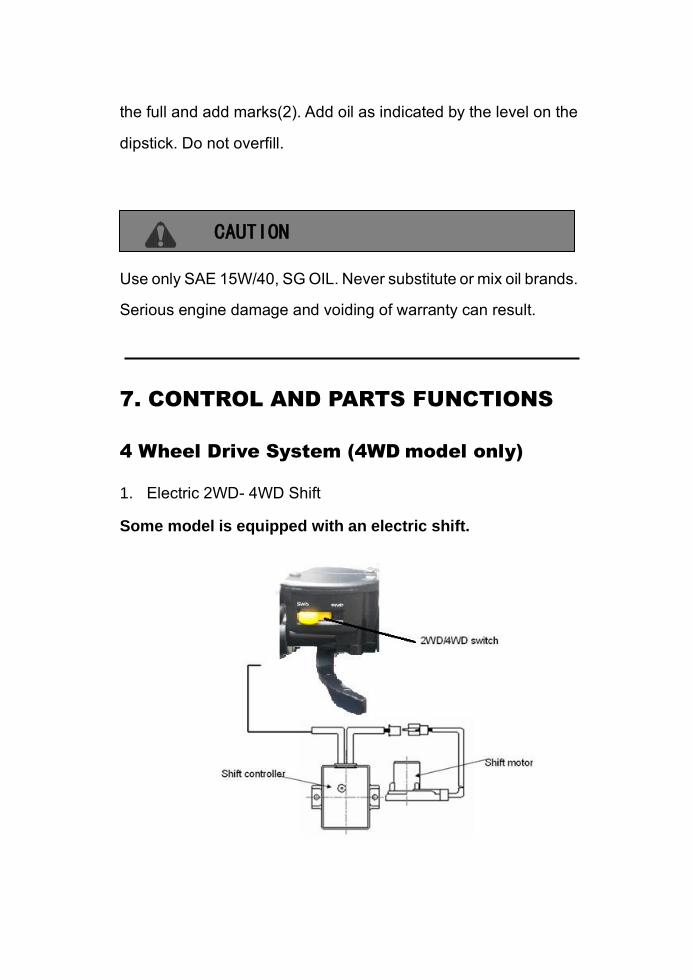
4 Wheel Drive System (4WD model only)
1. Electric 2WD- 4WD Shift
Some model is equipped with an electric shift.
CAUTION:
Always shift as the vehicle stop.
NOTE:
When shift 2WD/ 4WD, the mechanics in the front gear box maybe
still engaged/ disengaged, the mechanics would finally
disengaged/ engaged when rides on a hard surface or rides in
reverse.
The buzzer will beep if the procedure which list above is not done
in 1 minute.
Re-shift to stop the buzzer.
CAUTION
Do not switch on 4WD if the rear wheels are spining. This may
cause severe machine damage. When switch on 4WD, the button
will stay in 4WD position but 4WD mechanics maybe still
disengaged. Always apply throttle gently and let the wheels move
slightly to allow the 4WD mechanics finally engage. The 4WD
indicator on the speedometer will come on when 4WD engaged.
7. CONTROL AND PARTS FUNCTIONS
WARNING:
Extreme heavy steering is a symptom of malfunction of front
gearcase (differential), loss of control could result, even in 2WD
position. If you experience any symptoms from the steering, take
the ATV to your dealer for inspection and service.
NOTE:
Steering effort increase but remains balanced from left to right.
WARNING
Asymmetrical heavy steering is a symptom of malfunction of one
side inner or outer CV joints, loss of control could result, even in
2WD position. If you experience any symptoms from the steering,
take the ATV to your dealer for inspection and service.
WARNING
You must inspect your ATV each time before riding to ensure it is
in proper working order. If proper inspection is not done, severe
injury or death could result.
Pre-ride inspection
You can tell if malfunctions in one side CV joints by pulling the
handlebar to one side or riding the ATV in low speed. Steering
remains balanced from left to right in 2WD and 4WD positions..
8.STARTING THE ENGINE
Procedure for Starting a Cold Engine
WARNING
Never run an engine in an enclosed area. Carbon monoxide
exhaust gas is poisonous and can cause severe injury or death.
Always start engines outdoors.
CAUTION
You must allow your vehicle adequate warm up time before
operating or engine damage could result.
1. Place the transmission in neutral and reset the parking brake.
2. Turn the fuel tank valve to ON.
3. Sit on the vehicle.
4. Turn the engine stop switch to RUN.
5. Turn the ignition key to ON, apply the brake lever and press
the starter button.
6. Do not press the throttle more than 20% while starting the
engine.
7. Activate the starter for a maximum of five seconds, releasing
the button when the vehicle starts. If engine does not start,
release the starter for another five seconds. Repeat this
procedure until engine starts.
CAUTION
260cc and 300cc only equipped with an electric start system. If
the battery is under charging, the ATV will not run.
8.STARTING THE ENGINE
Using the Recoil Starter
The recoil starter is used to start the engine when the battery is
low ( but must more than 8 Volt).
To operate the recoil starter:
1. Grasp the starter grip firmly, when pull it out slowly
approximately 4 in (100 mm ).
2. Pull the grip up briskly and fully.
3. After the engine starts, allow the starter girp to return slowly.
CAUTION
This ATV is equipped with a recoil starter. But its engine is
equipped with a battery ignition system. If the battery is
under 8 Volt, the engine will not start.
CAUTION
Some resistance should be perceived when pulling gently the
starter cord. To start the engine, give a rapid pull at the cord, being
careful of a kickback in reverse as severe injury may result.

8.STARTING THE ENGINE
When and how to use the CHOKE
Normal Air Temperature 10°~35℃
1. Move the choke lever ① left to the fully ON (A) position, if the
engine is cold.
2. With the throttle closed, press the starter button.
Pressing the electric starter button for more than 5 seconds at
a time may casue the starter to overheat and damage the
starter. Release the starter button for approximately 10
seconds before pressing it again.
3. Immediately after the engine starts, operate the choke knob
to keep fast idle.
4. Continue warming up the engine until it runs smoothly and
responds to the throttle with the choke knob in the fully OFF
(B) position.
5. If idling is unstable, open the throttle slightly.
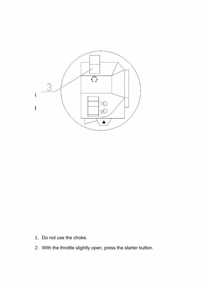
8.STARTING THE ENGINE
High Air Temperature 35℃
1. Do not use the choke.
2. With the throttle slightly open, press the starter button.
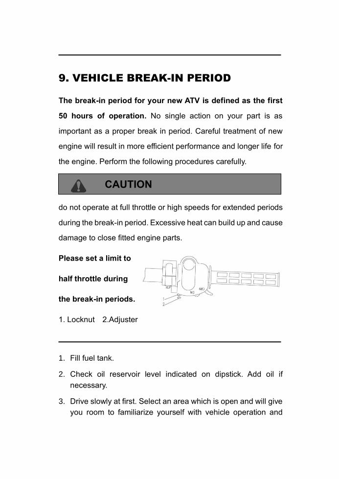
9. VEHICLE BREAK-IN PERIOD
The break-in period for your new ATV is defined as the first
50 hours of operation. No single action on your part is as
important as a proper break in period. Careful treatment of new
engine will result in more efficient performance and longer life for
the engine. Perform the following procedures carefully.
CAUTION
do not operate at full throttle or high speeds for extended periods
during the break-in period. Excessive heat can build up and cause
damage to close fitted engine parts.
Please set a limit to
half throttle during
the break-in periods.
1. Locknut 2.Adjuster
1. Fill fuel tank.
2. Check oil reservoir level indicated on dipstick. Add oil if
necessary.
3. Drive slowly at first. Select an area which is open and will give
you room to familiarize yourself with vehicle operation and
handling.
4. Vary the throttle positions. Do not operate at sustained idle.
5. Perform regular checks on fluid levels, controls and all
important areas on the vehicle as outlined earlier on the daily
pre-ride inspection checklist found in”4.daily pre-ride
inspection”.
6. Don’t pull loads.
7. Break in oil and filter. Change at 20 hours or 500 miles/800km.
10. RIDING GEAR
Safe Riding Gear
Always wear clothing suite to the type of riding you are doing. ATV
riding requires special protective clothing which will make you fell
more comfortable and reduce chances of injury.
1. Helmet
Your helmet is the most important piece of protective gear for safe
riding. A helmet can prevent a severe head injury.
Select an approved helmet.
2. Eye Protection
A pair of goggles or helmet face shield offer the best protection for
your eyes.
3. Gloves (off-road style)

4. Boots
A pair of strong over the calf type boots with heels, such as mo-
to-cross boots.
5. Clothing
To protect your body, long sleeves and pants should always be
worn. Riding pants with kneepads, a jersey and shoulder pads
provide the best protection.
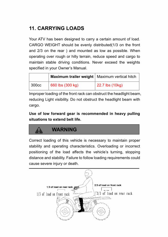
11. CARRYING LOADS
Your ATV has been designed to carry a certain amount of load.
CARGO WEIGHT should be evenly distributed(1/3 on the front
and 2/3 on the rear ) and mounted as low as possible. When
operating over rough or hilly terrain, reduce speed and cargo to
maintain stable driving conditions. Never exceed the weights
specified in your Owner’s Manual.
Maximum trailer weight Maximum vertical hitch
300cc 660 lbs (300 kg) 22.7 lbs (10kg)
Improper loading of the front rack can obstruct the headlight beam,
reducing Light visibility. Do not obstruct the headlight beam with
cargo.
Use of low forward gear is recommended in heavy pulling
situations to extend belt life.
WARNING
Correct loading of this vehicle is necessary to maintain proper
stability and operating characteristics. Overloading or incorrect
positioning of the load affects the vehicle’s turning, stopping
distance and stability. Failure to follow loading requirements could
cause severe injury or death.
11. CARRYING LOADS
Important Safeguards
To reduce risk of injury or machine damage when carrying loads,
read and follow the warnings listed below:
REDUCE SPEED AND ALLOW GREATED DISTANCE FOR
BRAKING WHEN CARRYING CARGO.
CARGO WEIGHT DISTRIBUTION should be 1/3 on the front
rack and 2/3 on the rear rack. When operating over rough or
hilly terrain, reduce speed and cargo to maintain stable driving
conditions. Carrying loads on one rack only increases the
possibility of vehicle tip over.
HEAVY LOADS CAN CAUSE BRAKING AND CONTROL
PROBLEMS. Use extreme caution when applying brakes with
a loaded vehicle. Avoid terrain or situations which may require
backing downhill.
ALL LOADS MUST BE SECURED BEFORE MOVING
VEHICLE. Unsecured loads can create unstable operating
condition, which could result in loss of control of vehicle.
LOADS MUST BE CARRIED AS LOW ON THE RACKS AS
POSSIBLE。 Carrying loads high on the racks raises the
center or gravity of the vehicle and creates a less stable
operating condition. When cargo loads are carried high on the
racks, the weight of the loads must be reduced to maintain
stable operating conditions.
OPERATE ONLY WITH STABLE AND SAFELY ARRANGED
LOADS. Avoid handling off-centered loads which cannot be
centered. Always attach the tow load to the hitch point
designated for your ATV.
EXTREME CAUTION MUST BE USED. Avoid operating with
loads extending over the rack sides. Stability and
maneuverability may be adversely affected, causing the
vehicle to overturn.
DO NOT BLOCK THE HEADLIGHT/TAILIGHT AND THE
REFLECTORS when carrying loads on the racks.
DO NOT TRAVEL FASTER THAN THE RECOMMENDED
SPEEDS. Vehicle should never exceed 10 mph (16km/h)
while towing a load on a level grass surface. Vehicle speed
11. CARRYING LOADS
should never exceed 5 mph(8km/h) when towing loads in
rough terrain, while cornering, or while ascending or
descending a hill
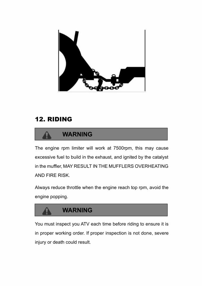
Use A Safety Chain
A safety chain will help control drawn machinery should it
separate from the tractor drawbar.
Use a chain with the strength rating equal to or greater than
the gross weight of the towed machinery.
Attach the chain to the tractor drawbar support or other
specified anchor location. Allow only enough slack in the
chain to permit turning.
Do not use safety chain for towing.
12. RIDING
WARNING
The engine rpm limiter will work at 7500rpm, this may cause
excessive fuel to build in the exhaust, and ignited by the catalyst
in the muffler, MAY RESULT IN THE MUFFLERS OVERHEATING
AND FIRE RISK.
Always reduce throttle when the engine reach top rpm, avoid the
engine popping.
WARNING
You must inspect you ATV each time before riding to ensure it is
in proper working order. If proper inspection is not done, severe
injury or death could result.

See“4.DAILY PRE-RIDE INSPECTION”
1. Sit upright with both feet on footrests and both hand on the
handlebars.
2. After starting the engine and allowing it to warm up, shift the
transmission into gear.
3. Check your surroundings and determine your path of travel.
4. Release the parking brake.
5. Slowly depress the throttle with your right thumb and begin
driving .Vehicle speed is controlled by the amount of throttle
opening.
6. Drive slowly, practice maneuvering and using the throttle and
brakes on level surfaces
12. RIDING
Making turns
Practice making turns at slow speeds
This ATV is equipped with a solid rear axle which drives both
rear wheels equally at all times. This means that the wheel on the
outside of the turn must travel a greater distance than the inside
wheels when turning and the inside tire must slip traction slightly.
To turn, steer in the direction of the turn leaning your upper body

to the inside of the turn while supporting your weight on the outer
footrest. This technique alters the balance of traction between the
rear wheels allowing the turn to be made smoothly. The same
leaning technique should be used for turning in reverse
WARNING
Avoid turning at sharp angles in reverse as tip over and severe
injury may result.
12. Operating procedure
Riding on slippery surfaces
Whenever riding on slippery surface such as wet trails or
loose gravel, or during cold freezing weather, special
attention must be paid to prevent vehicle turnover.
Always:
1. Slow down when entering slippery areas.
2. Maintain a high level of alertness, reading the trail and
avoiding quick, sharp turns which can cause skids.
3. Correct a skid by turning the handlebars in the direction of the
skid and shifting your body weight forward.
4. Never apply brakes during a skid. Complete loss of ATV
control can result.
5. Do not operate on excessively slippery surfaces.
6. Always reduce speed and use additional caution.
WARNING
Failure to exercise care when operating the ATV on slippery
Surfaces can be dangerous.
Loss of tire traction and vehicle control can result in an accident,
including an overturn.
12. Operating procedure
Traveling Uphill
WARNING
Exercise extreme caution when traveling in hilly terrain.
Braking and handling are greatly affected. Loss of vehicle control
or overturning of the ATV could occur causing severe injury or
death.
Whenever traveling uphill always travel straight uphill and:
1. Avoid steep hills (15%maximum).
2. Keep both feet on the footrests.
3. Transfer you weight forword.
4. Proceed at a steady rate of speed and throttle opening.
5. Remain alert and be prepared to take emergency action. This
may include quick dismounting of the ATV.
12. Operating procedure
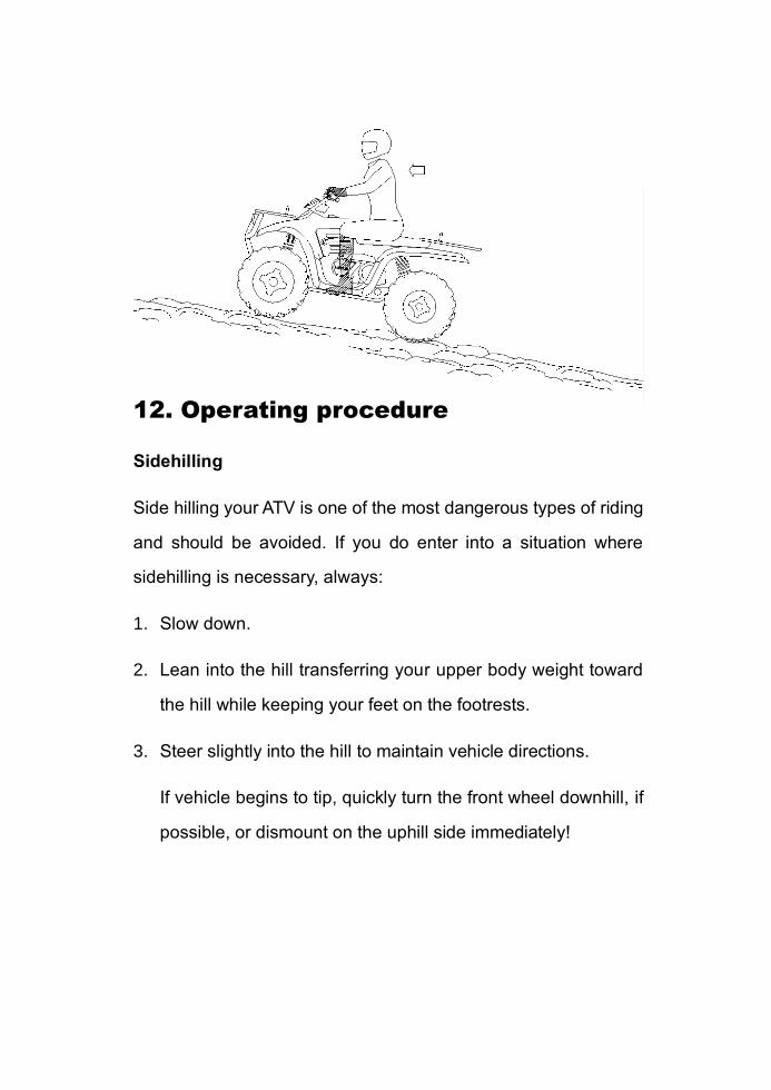
Sidehilling
Side hilling your ATV is one of the most dangerous types of riding
and should be avoided. If you do enter into a situation where
sidehilling is necessary, always:
1. Slow down.
2. Lean into the hill transferring your upper body weight toward
the hill while keeping your feet on the footrests.
3. Steer slightly into the hill to maintain vehicle directions.
If vehicle begins to tip, quickly turn the front wheel downhill, if
possible, or dismount on the uphill side immediately!
WARNING
Improperly crossing hills or turning on hills can be dangerous.
Loss of vehicle control or overturning of the ATV could occur
causing severe injury or death.
12. Operating procedure
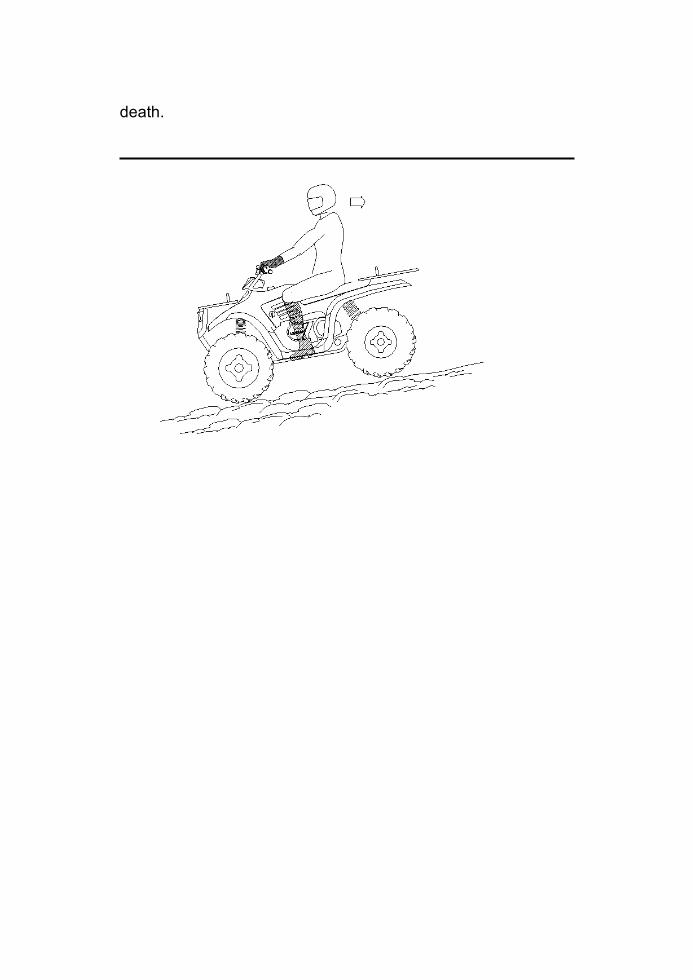
Traveling Downhill.
Whenever descending a hill, always:
1. Drive directly downhill.
2. Transfer your weight to the rear of the vehicle.
3. Slow down.
4. Apply the brakes slightly to aid in slowing.
Familiarize yourself with the auxiliary rear brake pedal and its use
in the event loss of normal service brakes occurs.
WARNING
Do not travel at excessive speeds. It is dangerous and can cause
loss of vehicle control and tipping, resulting in severe injury or
death.
12. Operating procedure
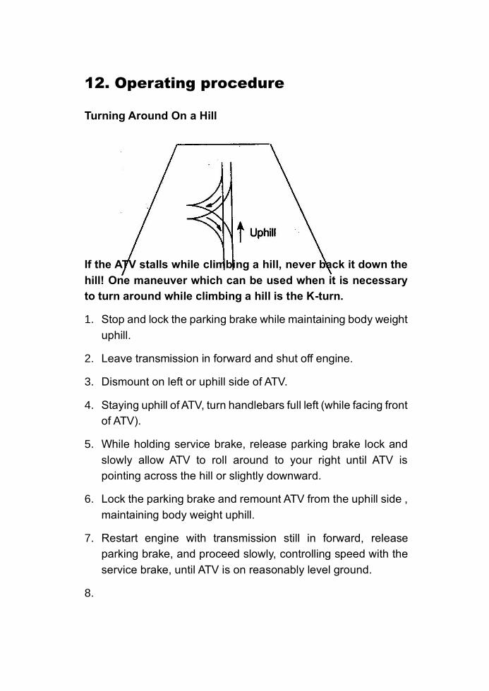
Turning Around On a Hill
If the ATV stalls while climbing a hill, never back it down the
hill! One maneuver which can be used when it is necessary
to turn around while climbing a hill is the K-turn.
1. Stop and lock the parking brake while maintaining body weight
uphill.
2. Leave transmission in forward and shut off engine.
3. Dismount on left or uphill side of ATV.
4. Staying uphill of ATV, turn handlebars full left (while facing front
of ATV).
5. While holding service brake, release parking brake lock and
slowly allow ATV to roll around to your right until ATV is
pointing across the hill or slightly downward.
6. Lock the parking brake and remount ATV from the uphill side ,
maintaining body weight uphill.
7. Restart engine with transmission still in forward, release
parking brake, and proceed slowly, controlling speed with the
service brake, until ATV is on reasonably level ground.
8.

WARNING
Avoid climbing steep hills. Loss of vehicle control or overturning
of the ATV could occur resulting in severe injury or death.

12. Operating procedure
Crossing Streams
Your ATV can operate through water up to maximum
recommended depths is 8 inch. Before fording steams
always:
1. Determine water depths and current.
2. Choose a crossing where both banks have gradual inclines.
3. Proceed slowly, avoiding rocks and obstacles if possible.
4. After crossing, dry the brakes by applying light pressure to the
lever until braking action is normal.
CAUTION
Never operating the ATV through deep or fast flowing water.
NOTE: After running the vehicle in water, it is critical your machine
is serviced as outlined in the maintenance chart see
“16.maintenance”.The following areas need special attention:
engine oil, transmission oil, rear gearcased, and all grease fittings.
12. RIDING
CAUTION
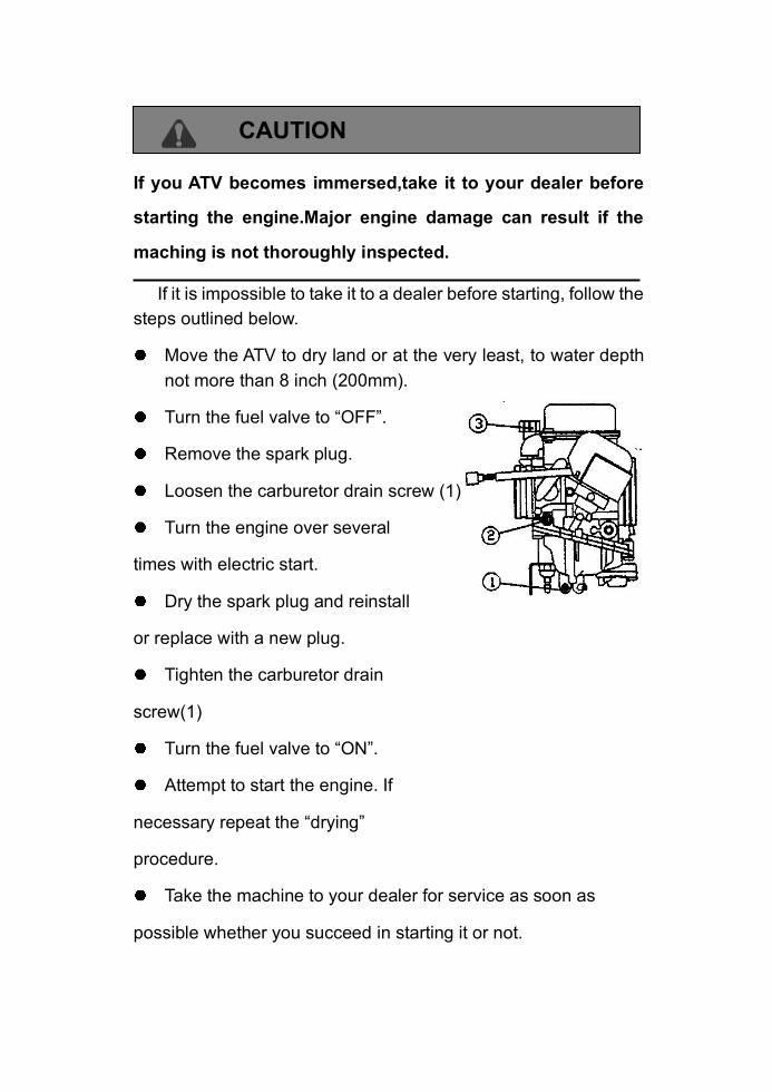
If you ATV becomes immersed,take it to your dealer before
starting the engine.Major engine damage can result if the
maching is not thoroughly inspected.
If it is impossible to take it to a dealer before starting, follow the
steps outlined below.
Move the ATV to dry land or at the very least, to water depth
not more than 8 inch (200mm).
Turn the fuel valve to “OFF”.
Remove the spark plug.
Loosen the carburetor drain screw (1)
Turn the engine over several
times with electric start.
Dry the spark plug and reinstall
or replace with a new plug.
Tighten the carburetor drain
screw(1)
Turn the fuel valve to “ON”.
Attempt to start the engine. If
necessary repeat the “drying”
procedure.
Take the machine to your dealer for service as soon as
possible whether you succeed in starting it or not.

If water has been ingested into the CVT system, take the ATV to
your dealer for service as soon as possible
12. Operating procedure
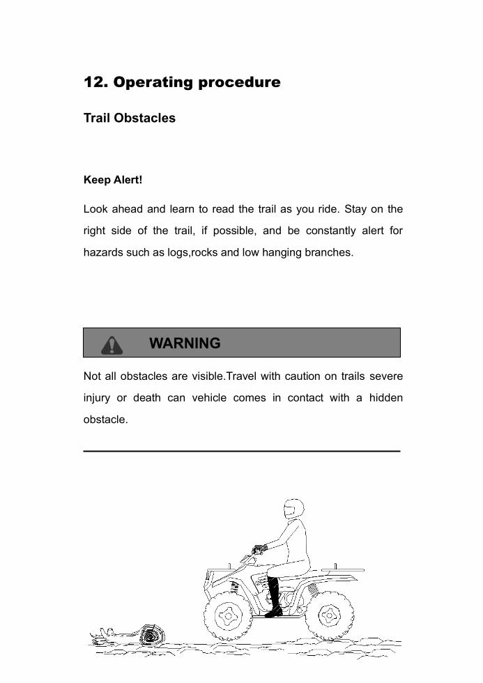
Trail Obstacles
Keep Alert!
Look ahead and learn to read the trail as you ride. Stay on the
right side of the trail, if possible, and be constantly alert for
hazards such as logs,rocks and low hanging branches.
WARNING
Not all obstacles are visible.Travel with caution on trails severe
injury or death can vehicle comes in contact with a hidden
obstacle.

12. Operating procedure
WARNING
Backing your ATV can be dangerous!
You could hit an obstacle or person behind you; or the vehicle
could tip over rearward on a steep incline causing severe injury or
death.
Backing up
1. Avoid backing up on steep inclines.
2. Always back slowly.
3. When in reverse, apply the brakes lightly for stopping.
4. Avoid turning at sharp angles in reverse.
5. Never open the throttle suddenly while backing.
NOTE: This ATV is equipped with a reverse speed limiter. Do not
operate at wide open throttle. Only open the throttle enough to
maintain a desired speed.
WARNING
Opening the throttle more than required may cause excessive fuel
to build in the exhaust, and ignited by the catalyst in the muffler,
MAY RESULT IN THE MUFFLERS OVERHEATING AND FIRE
RISK.
Never ride with engine popping more than 1 minutes.

12. Operating procedure
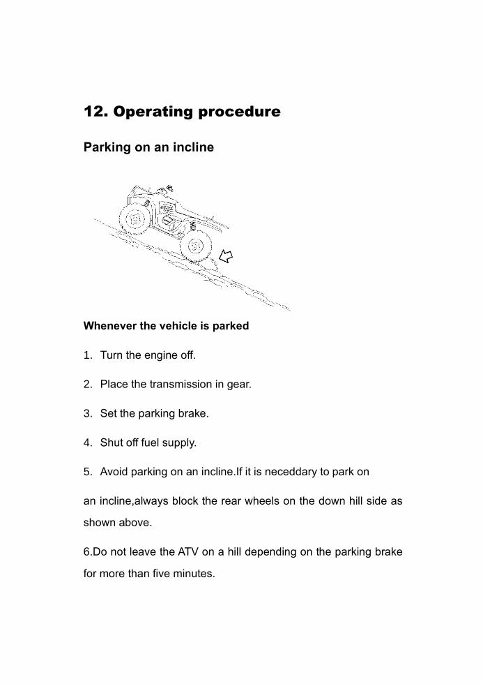
Parking on an incline
Whenever the vehicle is parked
1. Turn the engine off.
2. Place the transmission in gear.
3. Set the parking brake.
4. Shut off fuel supply.
5. Avoid parking on an incline.If it is neceddary to park on
an incline,always block the rear wheels on the down hill side as
shown above.
6.Do not leave the ATV on a hill depending on the parking brake
for more than five minutes.
13. CVT SYSTEM
CVT System
WARNING
The CVT system rotates at high speeds, creating large amounts
of force on clutch components. However, as the owner you have
the following responsibilities to make sure this system remains
safe:
Do not modify any component of the CVT system. Doing so
may reduce its strength so that a failure may occur at high speeds.
Any modification will cause the system to be out of balance,
creating vibration and additional loads on components.
Routine maintenance is the responsibility of the owner.
Always follow recommended maintenance procedures. See you
dealer!
The CVT housing must be securely in place during operation.
Failure to comply with this warning can result in severe injury or
death.
Low Range Use May Reduce CVT ( for 300cc)
Operating Temperatures
The basic operation of the CVT system is dependent on engine
speed and vehicle torque requirements. As engine speed
increased, the force exerted on the movable drive sheave by the
fly-weights also increases. This, in turn, increases the amount of
“pinch” applied to the drive belt. Similarly, if the engine speed
decrease, the amount of centrifugal; force decreases, reducing
the amount of belt “pinch.”
13. CVT SYSTEM
CVT System
On 300cc ATV, the approximate gear ratio difference between
high and low range is 1:2.05.This difference in gearing affects the
operation of the CVT, especially at speeds less than 7 MPH, due
to the system’s dependence on engine speed.
By switching to low range while operating at low ground speeds,
the air temperature in the clutch will be reduced. Reducing the
temperature inside the clutch cover extends the life of the CVT
components (belt, cover, etc.).
Adjust the center distance of the CVT ( 300cc only):
1. Remove crankcase filter cover, cover protector and crankcase
cover.
2. Loosen the left link bolts③, right link bolts② and engine
mounting bolts ①.
3. Adjust the supporting bolt and measure the size L,D;
4. Tighten the engine mounting bolts ①, right link bolts ②and
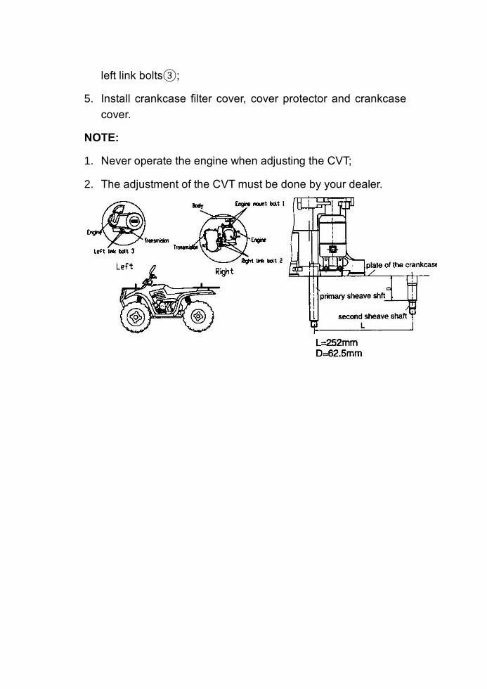
left link bolts③;
5. Install crankcase filter cover, cover protector and crankcase
cover.
NOTE:
1. Never operate the engine when adjusting the CVT;
2. The adjustment of the CVT must be done by your dealer.
13. CVT SYSTEM
When To Use Low Range ( 300cc only)
The following lists provide a guideline for when to use low range
rather than high.
Low Range
Basic operation at speeds less than 7 MPH (11km/h)
Heavy pulling
Riding through rough terrain (swamps, mountains, etc.)at low
ground speeds
High Range:
Basic operation at speeds greater than 7 MPH (11km/h)
High ground speeds
14. BATTERY
Battery
WARNING
Whenever removing the battery, disconnect the negative (black)
cable first. When reinstalling the battery, connect the negative
(black) cable last or an explosive situation could result causing
serious injury or death.
WARNING
Battery electrolyte is poisonous. It contains sulfuric acid. Serious
burns can result from contact with skin, eyes or clothing. Antidote:
External: Flush with water.
Internal: Drink large quantities of water or milk. Follow with milk
of magnesia, beaten egg, or vegetable oil. Call physician
immediately.
Eyes: Flush with water for 15minutes and get prompt medical
attention.
Batteries produce explosive gases. Keep sparks, flame,
cigarettes, etc. away. Ventilate when charging or using in an
enclosed space. Always shield eyes when working near batteries.
KEEP OUT OF REACH OF CHILDREN.
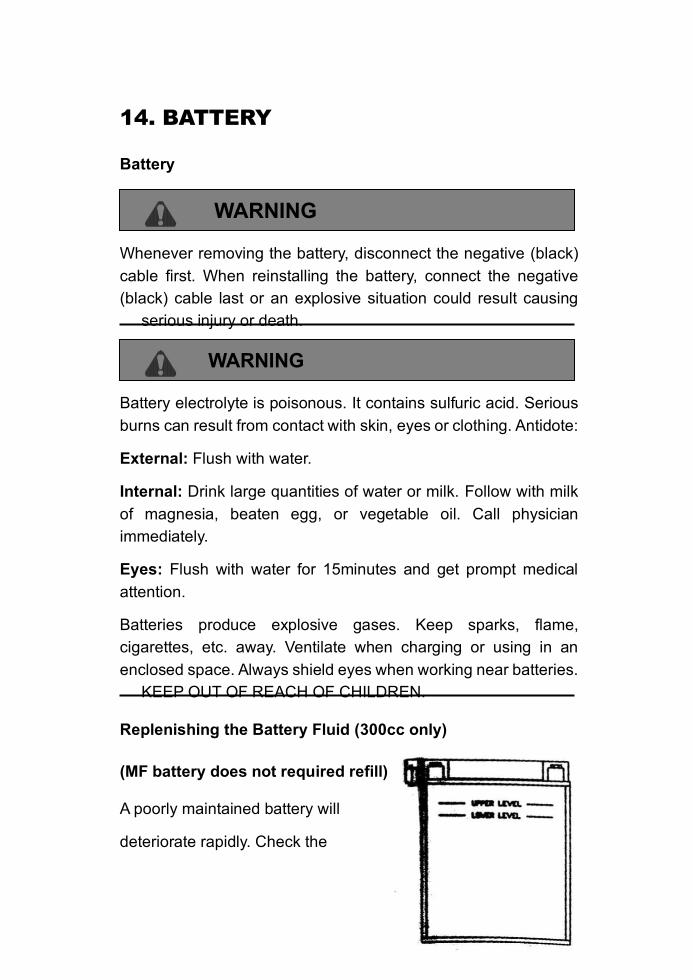
Replenishing the Battery Fluid (300cc only)
(MF battery does not required refill)
A poorly maintained battery will
deteriorate rapidly. Check the
battery fluid level often. The fluid
level should be kept between the
upper and lower level marks.
To refill use only distilled water.
Tap water contains minerals which
are harmful to a bettery.
14. BATTERY
Battery Removal
1. Disconnect hold down straps holding the electrical box and
battery in position and remove battery cover.
2. Remove the battery vent tube from the battery.
3. Disconnect the black (negative) battery cable first.
4. Disconnect the red(positive) battery cable next.
5. Lift the battery out of the ATV, being careful not to tip it
sideways and spill electrolyte.
CAUTION
If electrolyte spills, immediately wash it off with a solution of one
tablespoon baking soda and one cup water to prevent damage to
the ATV.
Battery Installation and Connections
WARNING
To avoid the possibility of explosion, always connect battery
cables in the order specified. Red (positive) cable first; black
(negative) cable last. An exploding battery can cause serious
injury or death.
Battery terminals and connections should be kept free of
corrosion.
If cleaning is necessary, remove the corrosion with a stiff wire
brush. Wash with a solution of one tablespoon baking soda and
one cup water. Rinse well with tap water and dry off with clean
rags. Coat the terminals with dialectic grease or petroleum jelly.
Be careful not to allow cleaning solution or tap water into the
battery.
14. BATTERY
1. Set the battery in its holder.
2. Install the battery vent tube. It must be free from obstructions
and securely installed. If not, battery gases could accumulate
and cause an explosion. The tube should be routed away from
the frame and body to prevent corrosion. Avoid skin contact
with electrolyte, severe burns could result.
3. First connect and tighten the red (positive) cable.
4. Second connect and tighten the black (negative) cable.
5. Reinstall battery cover and attach the hold down strap.
6. Verify that cables are properly routed.
NOTE:
When you ATV is placed in storage for one months or more,
the battery should be removed, charged to proper level, and
stored in a cool dry place.
Before reusing, take the battery to your dealer for testing and
recharging.
Power plug leads may need to be bent down so that battery cover
may be installed.
When installing a new battery, make certain it is fully charged
prior to it is initial use. Using a new battery that has not been fully
charged can damage the battery resulting in a shorter life of the
battery, It can also hinder vehicle performance.
CAUTION
Your ATV is equipped with a 14Ah Battery. This may no be
sufficient to provide power for optional equipment. When installing
optional equipment please upgrade your battery as necessary.
See your dealer for the proper battery.
14. BATTERY
Checking and Refueling
CAUTION
To avoid personal injury :
Do not smoke while refueling.
Be sure to stop the engine before refueling
1. Turn the key switch to “ON”, check the amount of fuel by fuel
gauge.
2. Fill fuel tank when fuel gauge shows 1/4 or less fuel in tank.
INPORTANT :
Do not permit dirt or trash to get into the fuel system.
Be careful not to let the fuel tank become empty, otherwise
air will enter the fuel system, necessitating bleeding before
next engine start.
Be careful not to spill during refueling. If fuel should spill, wipe
it off at once, or it may cause a fire.
To prevent condensation (water) accumulation in the fuel tank,
fill the tank before parking overnight.
15. EXHAUST SYSTEM
SYSTEM REGULATION
TAMPERING WITH NOISE CONTROL SYSTEM PROHIBITED!
CAUTION: Exhaust system components are very hot during and
after use of ATV.
Do not touch exhaust system components. Serious burns can
result.
Be especially careful when traveling through tall grass. The
potential for fire exists
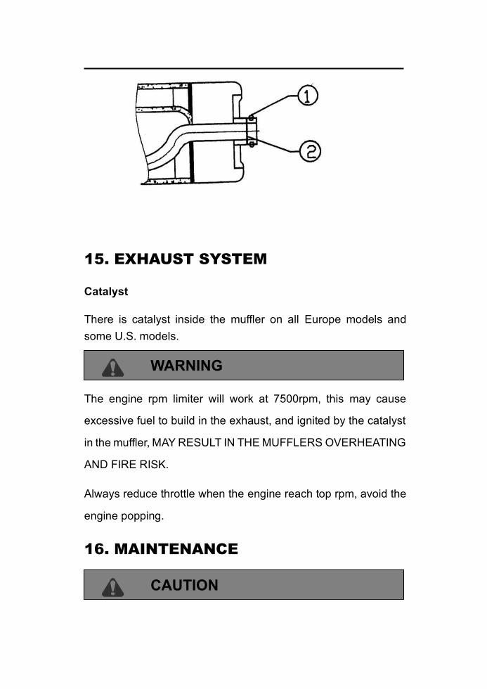
Spark Arrestor
The exhaust pipe must be periodically purged of accumulated
carbon as follows:
1. Remove the arrestor screw ① located on the bottom of the
muffler, pull out the arrestor (the mesh)②.
2. Clean the arrestor or replace it.
WARNING
When cleaning the spark arrestor, you must follow the safe guards
listed below to avoid serious injury.
Do not perform this operation immediately after the engine
has been run because the exhaust system becomes very hot.
Keep combustible materials away from exhaust system. Fire
may result.
15. EXHAUST SYSTEM
Catalyst
There is catalyst inside the muffler on all Europe models and
some U.S. models.
WARNING
The engine rpm limiter will work at 7500rpm, this may cause
excessive fuel to build in the exhaust, and ignited by the catalyst
in the muffler, MAY RESULT IN THE MUFFLERS OVERHEATING
AND FIRE RISK.
Always reduce throttle when the engine reach top rpm, avoid the
engine popping.
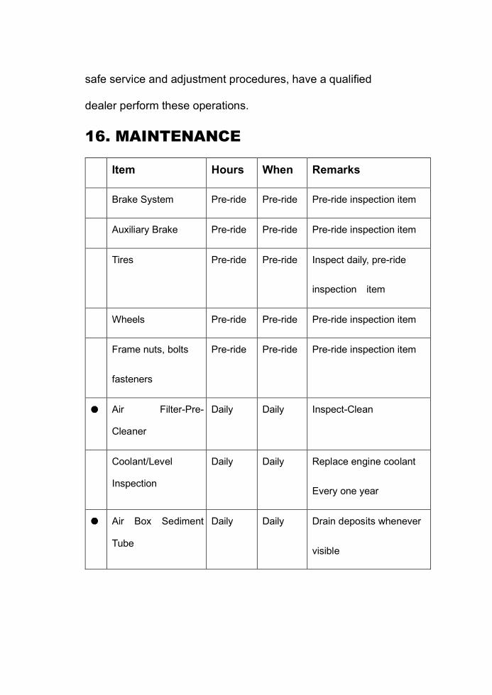
16. MAINTENANCE
CAUTION
Due to the nature of the adjustments marked with a D on the
following chart, it is recommended that service be performed by
an authorized dealer.
More often under severe use, such as dirty or wet conditions
to purge water or dirt contamination from grease fittings and
other critical components.
Periodic Maintenance Schedule
Careful periodic maintenance will help keep your vehicle in the
safest, most reliable condition. Inspection, adjustment and
lubrication intervals of important components are explained in the
following chart on the following pages.
Maintenance intervals are based upon average riding conditions
and an average vehicle speed of approximately 10 miles per hour.
Vehicles subjected to severe use, such as operation in wet or
dusty areas, should be inspected and serviced more frequently.
Inspect, clean, lubricate, adjust or replace parts as necessary.
NOTE: Inspection may reveal the need for replacement parts.
Always use genuine parts available from your dealer.
Service and adjustments are critical. If you are not familiar with
safe service and adjustment procedures, have a qualified
dealer perform these operations.
16. MAINTENANCE
Item Hours When Remarks
Brake System Pre-ride Pre-ride Pre-ride inspection item
Auxiliary Brake Pre-ride Pre-ride Pre-ride inspection item
Tires Pre-ride Pre-ride Inspect daily, pre-ride
inspection item
Wheels Pre-ride Pre-ride Pre-ride inspection item
Frame nuts, bolts
fasteners
Pre-ride Pre-ride Pre-ride inspection item
Air Filter-Pre-
Cleaner
Daily Daily Inspect-Clean
Coolant/Level
Inspection
Daily Daily Replace engine coolant
Every one year
Air Box Sediment
Tube
Daily Daily Drain deposits whenever
visible
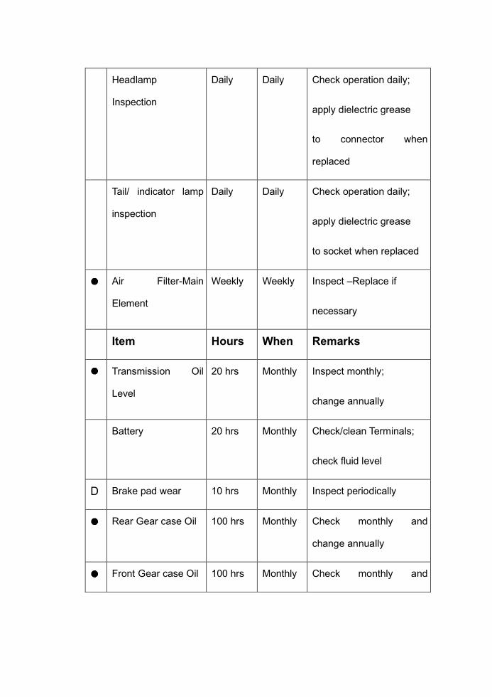
Headlamp
Inspection
Daily Daily Check operation daily;
apply dielectric grease
to connector when
replaced
Tail/ indicator lamp
inspection
Daily Daily Check operation daily;
apply dielectric grease
to socket when replaced
Air Filter-Main
Element
Weekly Weekly Inspect –Replace if
necessary
Item Hours When Remarks
Transmission Oil
Level
20 hrs Monthly Inspect monthly;
change annually
Battery 20 hrs Monthly Check/clean Terminals;
check fluid level
D Brake pad wear 10 hrs Monthly Inspect periodically
Rear Gear case Oil 100 hrs Monthly Check monthly and
change annually
Front Gear case Oil 100 hrs Monthly Check monthly and

( Only for 4WD) change annually
Engine Cylinder
Head and Cylinder
Base Fasteners
25 hrs 3 months Inspect (re-torque
required at first service
only)
General Lubrication 50 hrs 3 months Lubricate all fittings,
pivots, cables, etc.
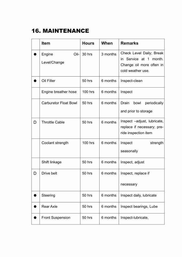
16. MAINTENANCE
Item Hours When Remarks
Engine Oil-
Level/Change
30 hrs 3 months Check Level Daily; Break
in Service at 1 month.
Change oil more often in
cold weather use.
Oil Filter 50 hrs 6 months Inspect-clean
Engine breather hose 100 hrs 6 months Inspect
Carburetor Float Bowl 50 hrs 6 months Drain bowl periodically
and prior to storage
D Throttle Cable 50 hrs 6 months Inspect –adjust, lubricate,
replace if necessary; pre-
ride inspection item
Coolant strength 100 hrs 6 months Inspect strength
seasonally
Shift linkage 50 hrs 6 months Inspect, adjust
D Drive belt 50 hrs 6 months Inspect, replace if
necessary
Steering 50 hrs 6 months Inspect daily, lubricate
Rear Axle 50 hrs 6 months Inspect bearings, Lube
Front Suspension 50 hrs 6 months Inspect-lubricate,
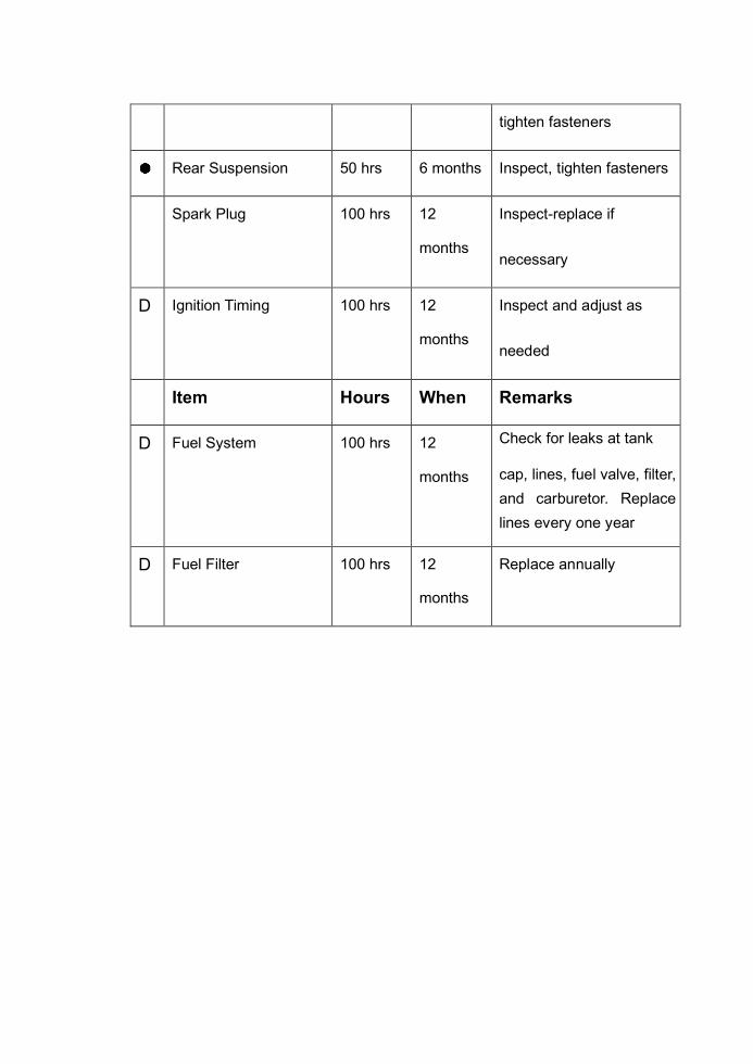
tighten fasteners
Rear Suspension 50 hrs 6 months Inspect, tighten fasteners
Spark Plug 100 hrs 12
months
Inspect-replace if
necessary
D Ignition Timing 100 hrs 12
months
Inspect and adjust as
needed
Item Hours When Remarks
D Fuel System 100 hrs 12
months
Check for leaks at tank
cap, lines, fuel valve, filter,
and carburetor. Replace
lines every one year
D Fuel Filter 100 hrs 12
months
Replace annually
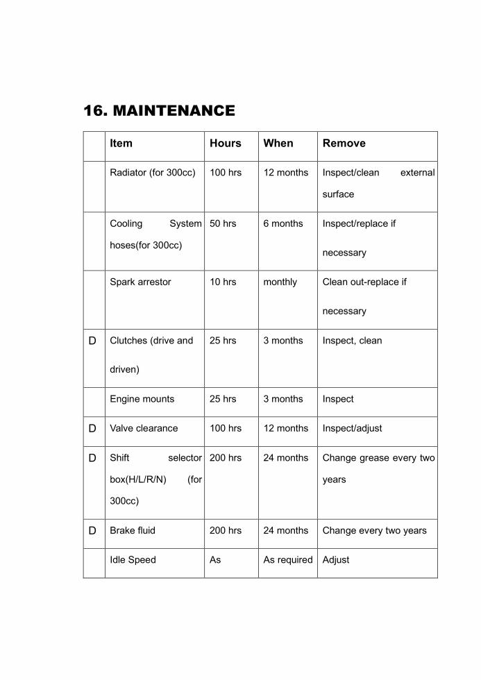
16. MAINTENANCE
Item Hours When Remove
Radiator (for 300cc) 100 hrs 12 months Inspect/clean external
surface
Cooling System
hoses(for 300cc)
50 hrs 6 months Inspect/replace if
necessary
Spark arrestor 10 hrs monthly Clean out-replace if
necessary
D Clutches (drive and
driven)
25 hrs 3 months Inspect, clean
Engine mounts 25 hrs 3 months Inspect
D Valve clearance 100 hrs 12 months Inspect/adjust
D Shift selector
box(H/L/R/N) (for
300cc)
200 hrs 24 months Change grease every two
years
D Brake fluid 200 hrs 24 months Change every two years
Idle Speed As As required Adjust
required
D Toe adjustment As
required
As required Periodic inspection,
adjust when parts are
replaced
Headlight Aim As
required
As required Adjust if necessary
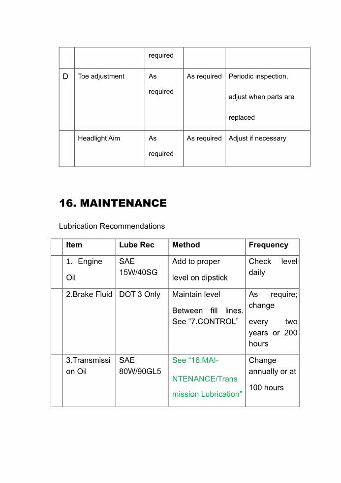
16. MAINTENANCE
Lubrication Recommendations
Item Lube Rec Method Frequency
1. Engine
Oil
SAE
15W/40SG
Add to proper
level on dipstick
Check level
daily
2.Brake Fluid DOT 3 Only Maintain level
Between fill lines.
See “7.CONTROL”
As require;
change
every two
years or 200
hours
3.Transmissi
on Oil
SAE
80W/90GL5
See “16.MAI-
NTENANCE/Trans
mission Lubrication”
Change
annually or at
100 hours

4.Rear Gear
case oil
SAE
80W/90GL5
See “16.MAI-
NTENANCE/Rear
Gear-case
Lubrication”
Change
annually or
at 100 hours
5.Front Gear
case oil (only
for 4WD)
SAE
80W/90GL5
See “16.MAI-
NTENANCE/Front
Gear-case
Lubrication”
Change
annually or
at 100 hours
16. MAINTENANCE
Lubrication Recommendations
Item Lube Rec Method Frequency
6. Front A-arm
pivot Shaft
Grease Locate fitting on
pivot shaft and
grease with grease
gun
Every 3
months or 50
hours
7.Steering Grease Locate fitting on Every 3
months or 50
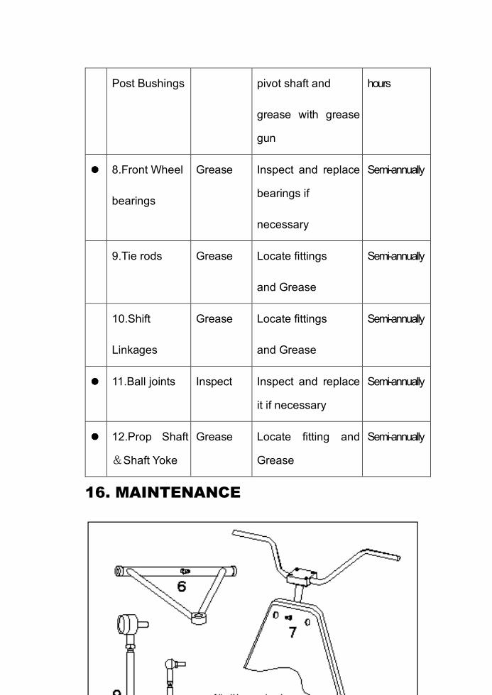
Post Bushings pivot shaft and
grease with grease
gun
hours
8.Front Wheel
bearings
Grease Inspect and replace
bearings if
necessary
Semi-annually
9.Tie rods Grease Locate fittings
and Grease
Semi-annually
10.Shift
Linkages
Grease Locate fittings
and Grease
Semi-annually
11.Ball joints Inspect Inspect and replace
it if necessary
Semi-annually
12.Prop Shaft
&Shaft Yoke
Grease Locate fitting and
Grease
Semi-annually
16. MAINTENANCE

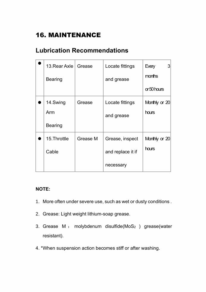
16. MAINTENANCE
Lubrication Recommendations
13.Rear Axle
Bearing
Grease Locate fittings
and grease
Every 3
months
or 50 hours
14.Swing
Arm
Bearing
Grease Locate fittings
and grease
Monthly or 20
hours
15.Throttle
Cable
Grease M Grease, inspect
and replace it if
necessary
Monthly or 20
hours
NOTE:
1. More often under severe use, such as wet or dusty conditions .
2. Grease: Light weight lithium-soap grease.
3. Grease M : molybdenum disulfide(MoS2 ) grease(water
resistant).
4. *When suspension action becomes stiff or after washing.

5. Hours are based on 10 mph(16Km/h) average.
16. MAINTENANCE
Periodic Maintenance Record
Use the following chart to record periodic maintenance work:
Maintenance
Interval
Performed
Servicing
Date
Servicing
Dealer or
Person
Remarks
First 5 Hrs
10 Hrs
15 Hrs
20 Hrs
25 Hrs
50 Hrs
75 Hrs
100 Hrs

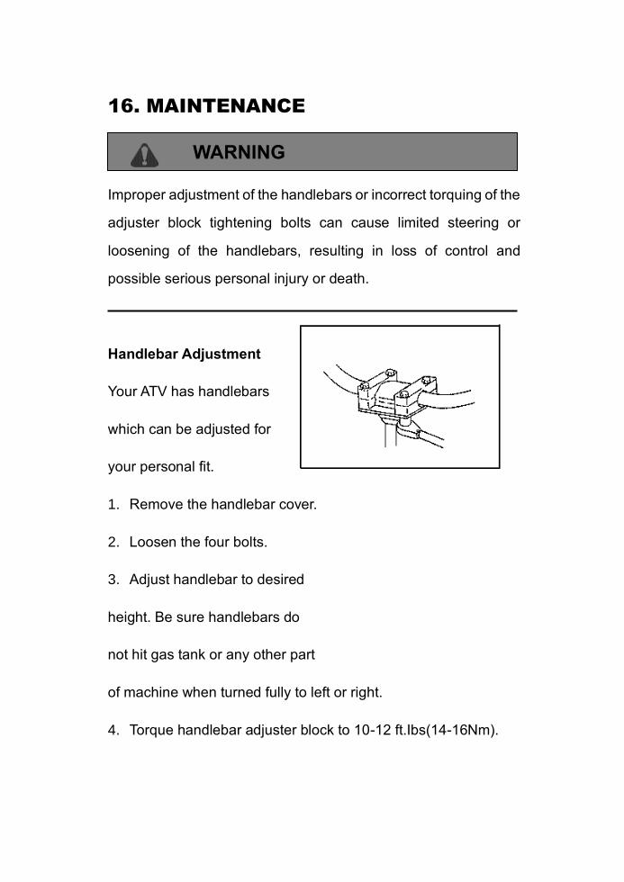
16. MAINTENANCE
WARNING
Improper adjustment of the handlebars or incorrect torquing of the
adjuster block tightening bolts can cause limited steering or
loosening of the handlebars, resulting in loss of control and
possible serious personal injury or death.
Handlebar Adjustment
Your ATV has handlebars
which can be adjusted for
your personal fit.
1. Remove the handlebar cover.
2. Loosen the four bolts.
3. Adjust handlebar to desired
height. Be sure handlebars do
not hit gas tank or any other part
of machine when turned fully to left or right.
4. Torque handlebar adjuster block to 10-12 ft.Ibs(14-16Nm).
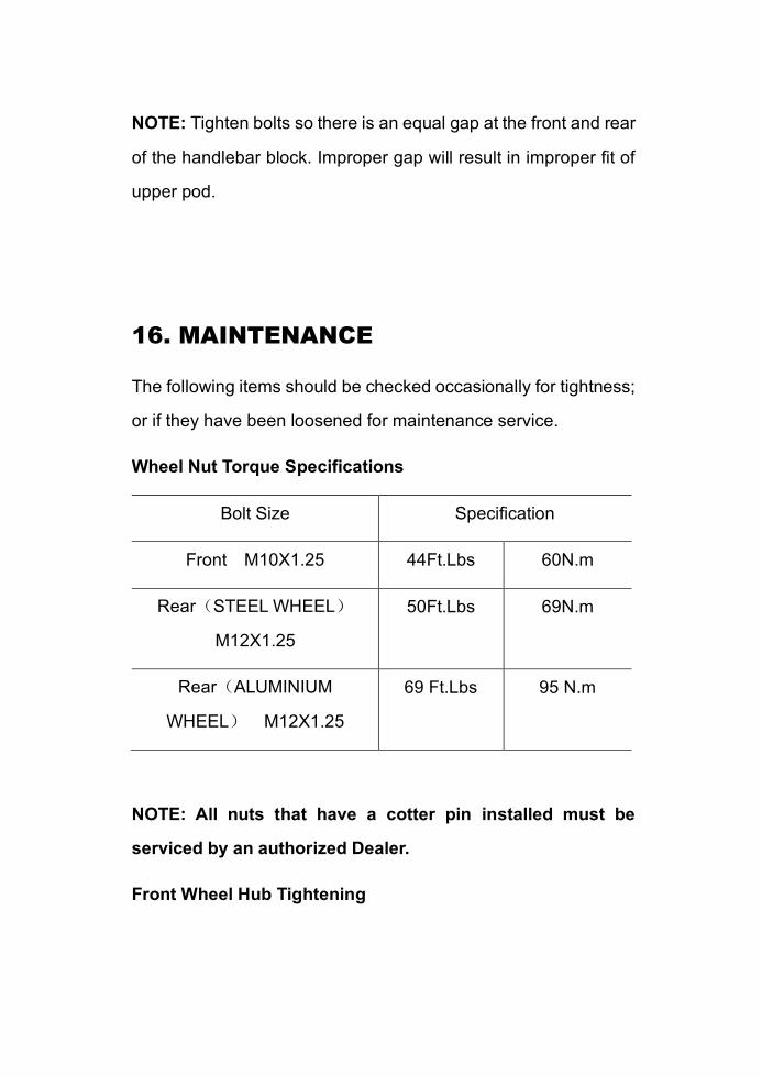
NOTE: Tighten bolts so there is an equal gap at the front and rear
of the handlebar block. Improper gap will result in improper fit of
upper pod.
16. MAINTENANCE
The following items should be checked occasionally for tightness;
or if they have been loosened for maintenance service.
Wheel Nut Torque Specifications
Bolt Size Specification
Front M10X1.25 44Ft.Lbs 60N.m
Rear(STEEL WHEEL)
M12X1.25
50Ft.Lbs 69N.m
Rear(ALUMINIUM
WHEEL) M12X1.25
69 Ft.Lbs 95 N.m
NOTE: All nuts that have a cotter pin installed must be
serviced by an authorized Dealer.
Front Wheel Hub Tightening
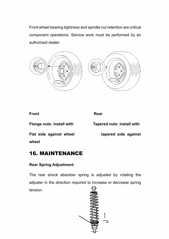
Front wheel bearing tightness and spindle nut retention are critical
component operations. Service work must be performed by an
authorized dealer.
Front Rear
Flange nuts: install with Tapered nuts: install with
Flat side against wheel tapered side against
wheel
16. MAINTENANCE
Rear Spring Adjustment
The rear shock absorber spring is adjusted by rotating the
adjuster in the direction required to increase or decrease spring
tension.
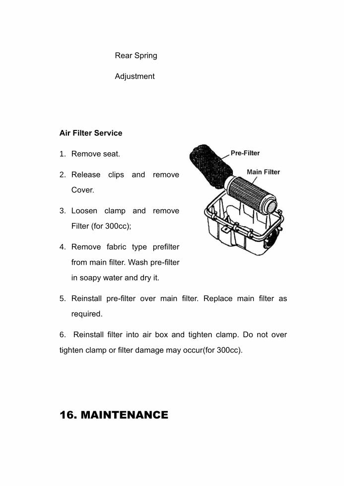
Rear Spring
Adjustment
Air Filter Service
1. Remove seat.
2. Release clips and remove
Cover.
3. Loosen clamp and remove
Filter (for 300cc);
4. Remove fabric type prefilter
from main filter. Wash pre-filter
in soapy water and dry it.
5. Reinstall pre-filter over main filter. Replace main filter as
required.
6. Reinstall filter into air box and tighten clamp. Do not over
tighten clamp or filter damage may occur(for 300cc).
16. MAINTENANCE
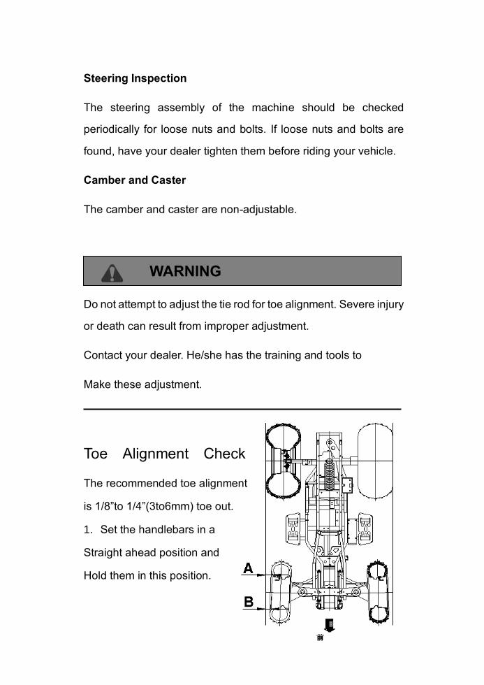
Steering Inspection
The steering assembly of the machine should be checked
periodically for loose nuts and bolts. If loose nuts and bolts are
found, have your dealer tighten them before riding your vehicle.
Camber and Caster
The camber and caster are non-adjustable.
WARNING
Do not attempt to adjust the tie rod for toe alignment. Severe injury
or death can result from improper adjustment.
Contact your dealer. He/she has the training and tools to
Make these adjustment.
Toe Alignment Check
The recommended toe alignment
is 1/8”to 1/4”(3to6mm) toe out.
1. Set the handlebars in a
Straight ahead position and
Hold them in this position.
2. Measure A and B,A minus
B should be 1/16” to 1/8”
(1.5 to 3mm).
3. If this measurement needs
to be adjusted, contact your
dealer for service.
16. MAINTENANCE
Front Brake
WARNING
Once a bottle of brake fluid is opened, use what is necessary
and discard the rest. Do not store or use a partial bottle of brake
fluid. Brake fluid is hygroscopic, meaning it rapidly absorbs
moisture from the air. This causes the boiling temperature of the
brake fluid to drop, which can lead to early brake fade and the
possibility of serious injury.
The front brake is hydraulic disc brakes which is depressing the
foot pedal (also brake lever on handlebar for 300cc ATV) on the
side of the right floorboard. These brakes are self-adjusting and
require no adjustment.
The following checks are recommended to keep the brake system
in good operating condition. How often they need checking
depends upon the type of driving that has been done.
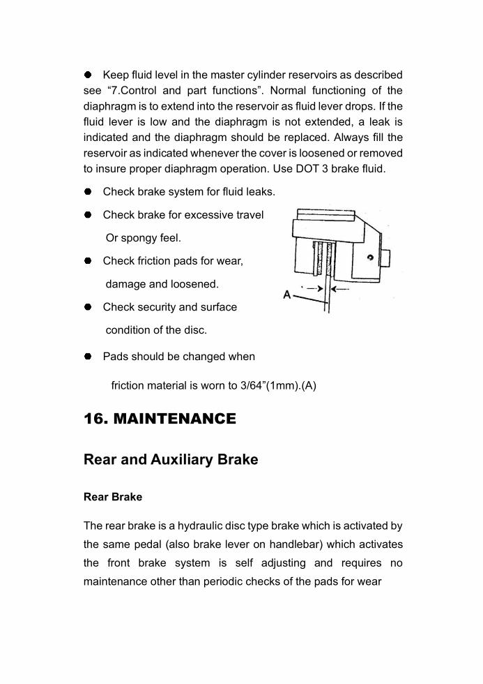
Keep fluid level in the master cylinder reservoirs as described
see “7.Control and part functions”. Normal functioning of the
diaphragm is to extend into the reservoir as fluid lever drops. If the
fluid lever is low and the diaphragm is not extended, a leak is
indicated and the diaphragm should be replaced. Always fill the
reservoir as indicated whenever the cover is loosened or removed
to insure proper diaphragm operation. Use DOT 3 brake fluid.
Check brake system for fluid leaks.
Check brake for excessive travel
Or spongy feel.
Check friction pads for wear,
damage and loosened.
Check security and surface
condition of the disc.
Pads should be changed when
friction material is worn to 3/64”(1mm).(A)
16. MAINTENANCE
Rear and Auxiliary Brake
Rear Brake
The rear brake is a hydraulic disc type brake which is activated by
the same pedal (also brake lever on handlebar) which activates
the front brake system is self adjusting and requires no
maintenance other than periodic checks of the pads for wear

Pads should be changed when the friction material is worn to
3/64”(1mm).
Inspect the brake disc spline and pad wear surface for
excessive wear.
Auxiliary Brake Systems
Your ATV’s auxiliary brake system is intended to be used as a
backup for the main brake system. Should the main system fail,
the rear brake can be activated by the brake lever being moving
toward the handlebar. The hydraulic brake system will not require
adjustment.
Checking
Although the parking brake has been adjusted at the factory, the
brake should be checked for proper operation. The mechanical
brake must be maintained to be fully functional.
1. With the engine off, apply the parking brake lever and attempt
to move the ATV.
2. If the rear wheels are locked, it is adjusted properly.
3. If the wheels are not locked, it must be adjusted.
16. MAINTENANCE
Adjusting
To adjust (set up) the mechanical parking brake, use the
following procedure
Note: The adjusting on the caliper is for the wear out of the
pads.
1. With the engine off, loosen the adjustor① on the lever.
2. Loosen the jam nut of the adjuster on the caliper.
3. Turn the adjuster (bolt) CW (clockwise) by hand till the pad
touch the brake disc, turn the adjuster bolt CCW
(counterclockwise) by 1/4 to one turn for 10 to 20mm free play at
the end of the parking lever.
4. Tighten the jam nuts securely against the adjusters.
5. Make sure the rear wheels turns freely without dragging.
6. Turn the adjustor (the one on the lever) and apply the lever.
While adjusting, it is important you apply the lever back and forth
for operation, free play and the locking of the parking position.
7. Make sure the rear wheels turns freely without dragging and
parking brake works properly.
CAUTION Don’t over tighten the adjustor. Free play of the lever:
20mm.
8. Field test for parking. It must be capable of holding the laden
ATV stationary on an 18% up and down gradient.
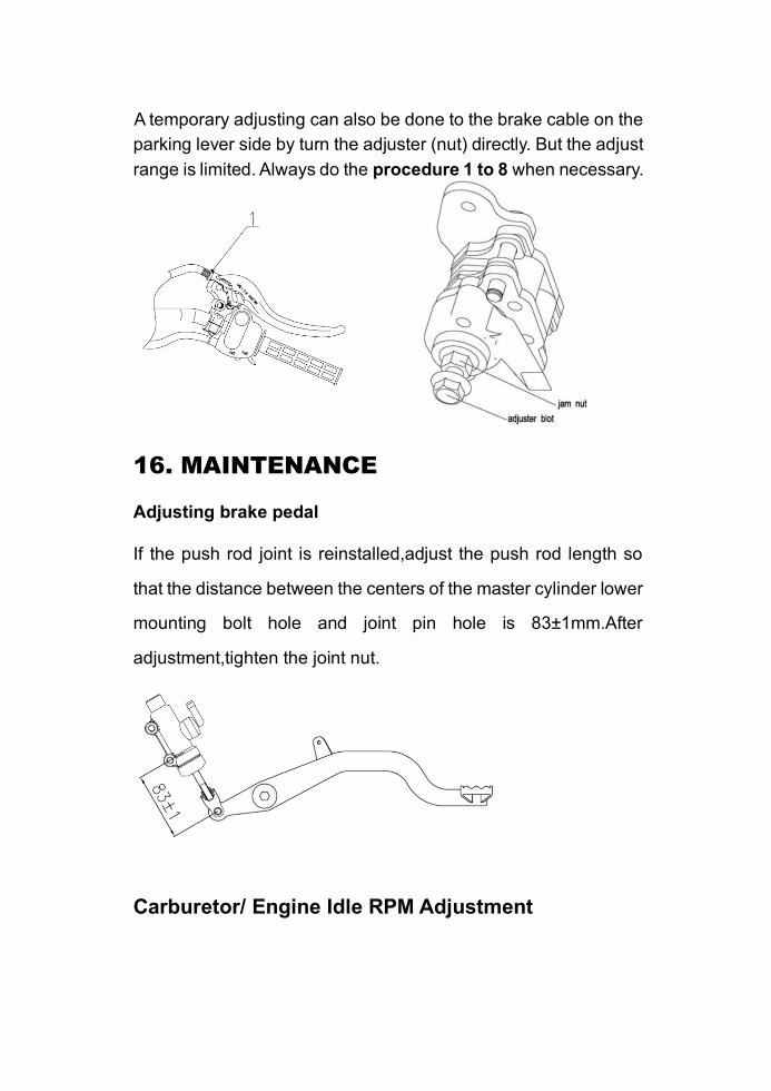
A temporary adjusting can also be done to the brake cable on the
parking lever side by turn the adjuster (nut) directly. But the adjust
range is limited. Always do the procedure 1 to 8 when necessary.
16. MAINTENANCE
Adjusting brake pedal
If the push rod joint is reinstalled,adjust the push rod length so
that the distance between the centers of the master cylinder lower
mounting bolt hole and joint pin hole is 83±1mm.After
adjustment,tighten the joint nut.
Carburetor/ Engine Idle RPM Adjustment
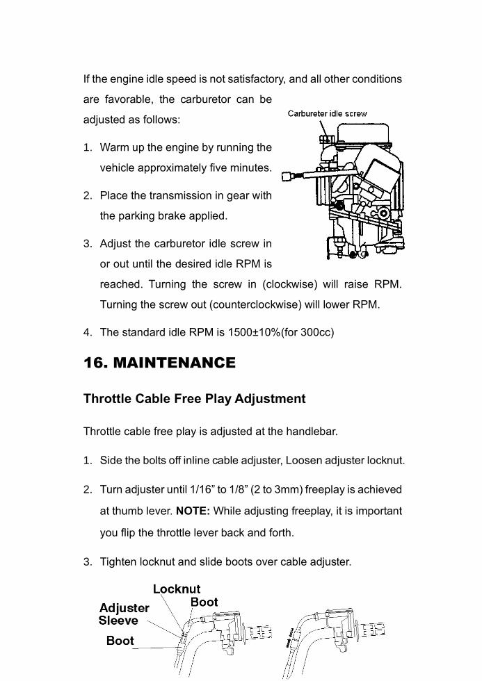
If the engine idle speed is not satisfactory, and all other conditions
are favorable, the carburetor can be
adjusted as follows:
1. Warm up the engine by running the
vehicle approximately five minutes.
2. Place the transmission in gear with
the parking brake applied.
3. Adjust the carburetor idle screw in
or out until the desired idle RPM is
reached. Turning the screw in (clockwise) will raise RPM.
Turning the screw out (counterclockwise) will lower RPM.
4. The standard idle RPM is 1500±10%(for 300cc)
16. MAINTENANCE
Throttle Cable Free Play Adjustment
Throttle cable free play is adjusted at the handlebar.
1. Side the bolts off inline cable adjuster, Loosen adjuster locknut.
2. Turn adjuster until 1/16” to 1/8” (2 to 3mm) freeplay is achieved
at thumb lever. NOTE: While adjusting freeplay, it is important
you flip the throttle lever back and forth.
3. Tighten locknut and slide boots over cable adjuster.
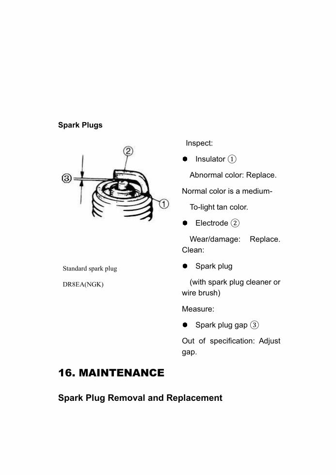
Spark Plugs
Inspect:
Insulator ①
Abnormal color: Replace.
Normal color is a medium-
To-light tan color.
Electrode ②
Wear/damage: Replace.
Clean:
Spark plug
(with spark plug cleaner or
wire brush)
Measure:
Spark plug gap ③
Out of specification: Adjust
gap.
16. MAINTENANCE
Spark Plug Removal and Replacement
Standard spark plug
DR8EA(NGK)
③ Gap:0.6-0.7mm
WARNING
Never attempt to remove a spark plug while the engine is warm.
The exhaust system or engine could burn you causing severe
injury.
Remove the spark plug by rotating counterclockwise.
Reverse the procedure for spark plug installation.
Torque to 17ft.Ibs (23N.m) (for 300cc).
Oil and Filter Change
The recommended oil change interval is 30 hours, or every 3
mouths, whichever comes first. Suggested break in oil change is
at 20 hours, or one mouth, whichever comes first. Severe use
operation requires more frequent service. Severe use includes
continuous duty in dusty or wet conditions, and cold weather
riding.
NOTE: Severe use cold weather riding is all riding below
10°F(-12℃), and riding between 10°F(-12℃) and 30°F(0℃) when
most trips are slow speed and less than 5 mph (8km/h).Be sure
to change the oil filter whenever changing oil
16. MAINTENANCE
CAUTION
Oil may be hot. Do not allow hot oil to come into contact with skin
as severe burns may result
1. Place vehicle on a level surface;
2. Run engine two or three minutes until warm, Stop engine;
3. Clean area around drain plug;
4. Place a drain pan beneath engine crankcase and remove
drain plug;
5. Allow oil to drain completely;
6. Replace sealing washer O-ring of drain plug;
7. Reinstall drain plug and torque to 14ft.Ibs (19N.m)
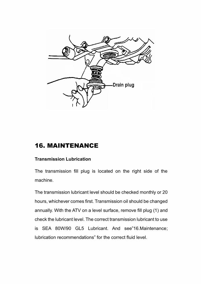
16. MAINTENANCE
Transmission Lubrication
The transmission fill plug is located on the right side of the
machine.
The transmission lubricant level should be checked monthly or 20
hours, whichever comes first. Transmission oil should be changed
annually. With the ATV on a level surface, remove fill plug (1) and
check the lubricant level. The correct transmission lubricant to use
is SEA 80W/90 GL5 Lubricant. And see”16.Maintenance;
lubrication recommendations” for the correct fluid level.
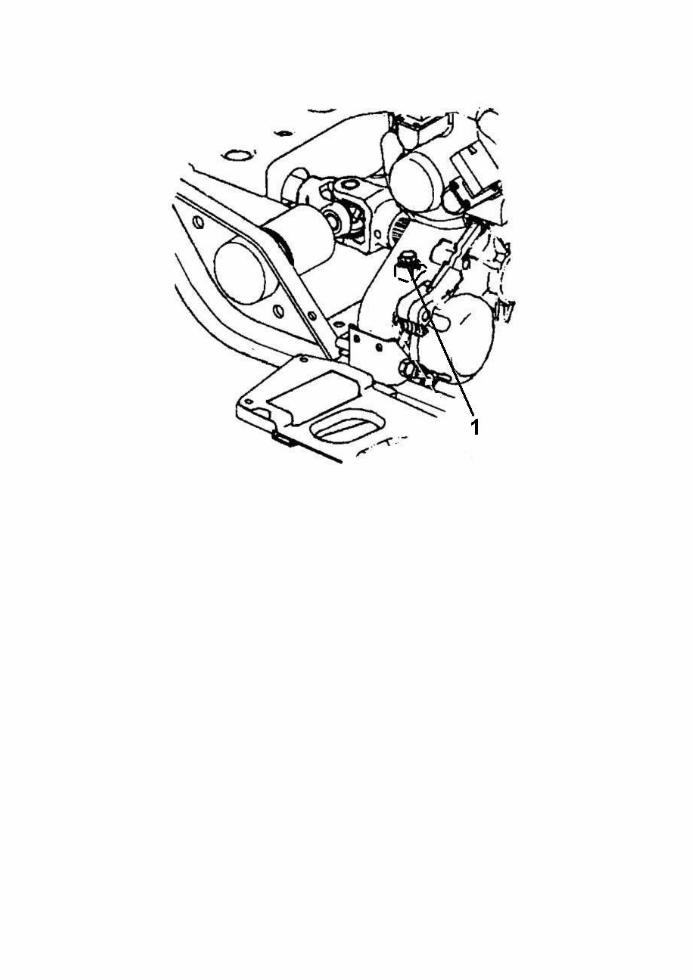
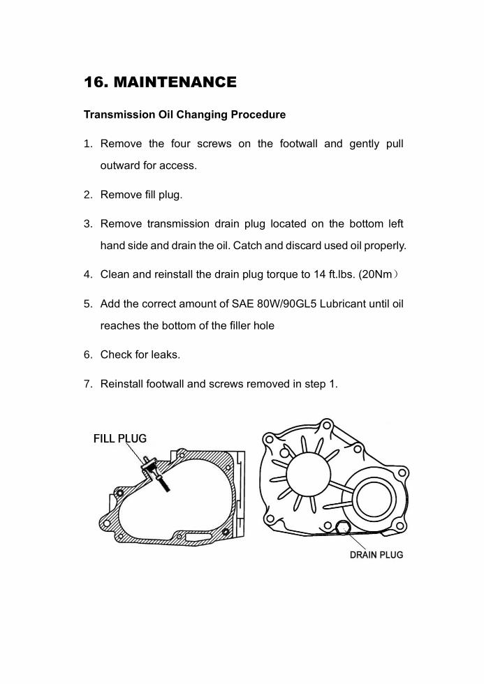
16. MAINTENANCE
Transmission Oil Changing Procedure
1. Remove the four screws on the footwall and gently pull
outward for access.
2. Remove fill plug.
3. Remove transmission drain plug located on the bottom left
hand side and drain the oil. Catch and discard used oil properly.
4. Clean and reinstall the drain plug torque to 14 ft.lbs. (20Nm)
5. Add the correct amount of SAE 80W/90GL5 Lubricant until oil
reaches the bottom of the filler hole
6. Check for leaks.
7. Reinstall footwall and screws removed in step 1.
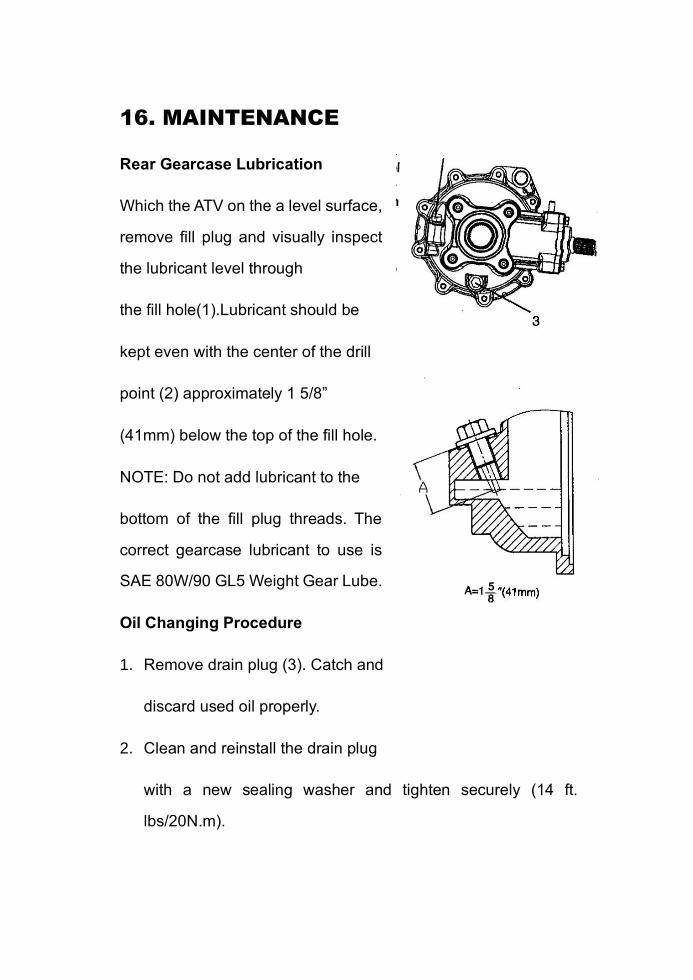
16. MAINTENANCE
Rear Gearcase Lubrication
Which the ATV on the a level surface,
remove fill plug and visually inspect
the lubricant level through
the fill hole(1).Lubricant should be
kept even with the center of the drill
point (2) approximately 1 5/8”
(41mm) below the top of the fill hole.
NOTE: Do not add lubricant to the
bottom of the fill plug threads. The
correct gearcase lubricant to use is
SAE 80W/90 GL5 Weight Gear Lube.
Oil Changing Procedure
1. Remove drain plug (3). Catch and
discard used oil properly.
2. Clean and reinstall the drain plug
with a new sealing washer and tighten securely (14 ft.
lbs/20N.m).
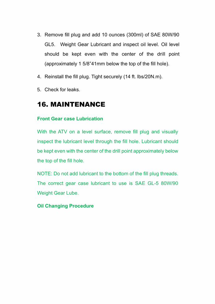
3. Remove fill plug and add 10 ounces (300ml) of SAE 80W/90
GL5. Weight Gear Lubricant and inspect oil level. Oil level
should be kept even with the center of the drill point
(approximately 1 5/8”41mm below the top of the fill hole).
4. Reinstall the fill plug. Tight securely (14 ft. lbs/20N.m).
5. Check for leaks.
16. MAINTENANCE
Front Gear case Lubrication
With the ATV on a level surface, remove fill plug and visually
inspect the lubricant level through the fill hole. Lubricant should
be kept even with the center of the drill point approximately below
the top of the fill hole.
NOTE: Do not add lubricant to the bottom of the fill plug threads.
The correct gear case lubricant to use is SAE GL-5 80W/90
Weight Gear Lube.
Oil Changing Procedure
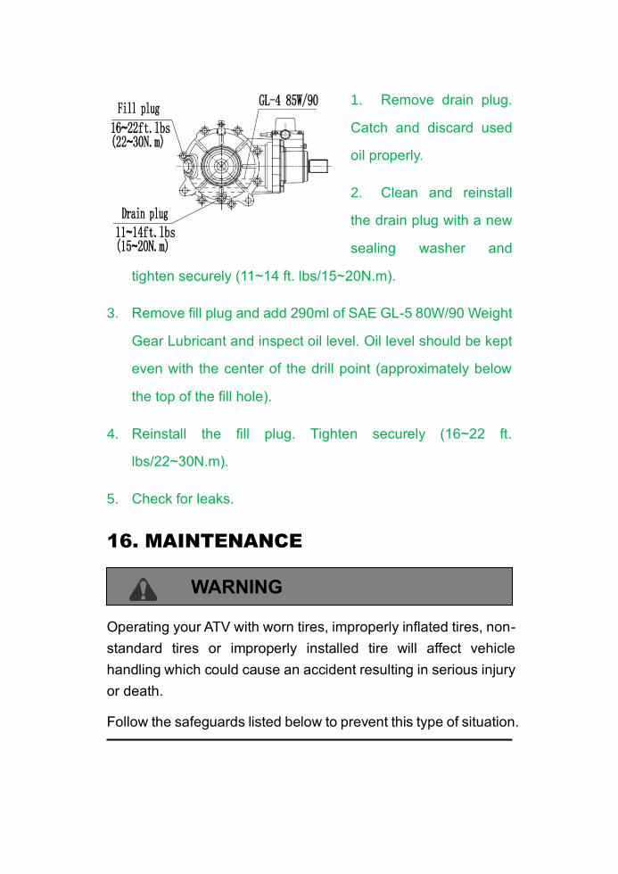
1. Remove drain plug.
Catch and discard used
oil properly.
2. Clean and reinstall
the drain plug with a new
sealing washer and
tighten securely (11~14 ft. lbs/15~20N.m).
3. Remove fill plug and add 290ml of SAE GL-5 80W/90 Weight
Gear Lubricant and inspect oil level. Oil level should be kept
even with the center of the drill point (approximately below
the top of the fill hole).
4. Reinstall the fill plug. Tighten securely (16~22 ft.
lbs/22~30N.m).
5. Check for leaks.
16. MAINTENANCE
WARNING
Operating your ATV with worn tires, improperly inflated tires, non-
standard tires or improperly installed tire will affect vehicle
handling which could cause an accident resulting in serious injury
or death.
Follow the safeguards listed below to prevent this type of situation.
Important Safeguards
Maintain proper tire pressure according to charts below. Improper
tire inflation may affect ATV maneuverability.
Do not use improper tires. The use of non-standard size or type
tires may affect ATV handling.
Make certain the wheels are installed properly. If wheels are
improperly installed it could affect vehicle handling and tire wear.
Wheel Removal Procedure
1. Stop the engine, place the transmission in gear and lock the
parking brake.
2. Loosen the wheel nuts slightly.
3. Elevate the side of the vehicle by placing a suitable stand
under the footrest frame.
4. Remove the wheel nuts and remove the wheel.
Tire Pressure
front rear
34.5kPa/5PSI 34.5kPa/5PSI
16. MAINTENANCE
Wheel Installation
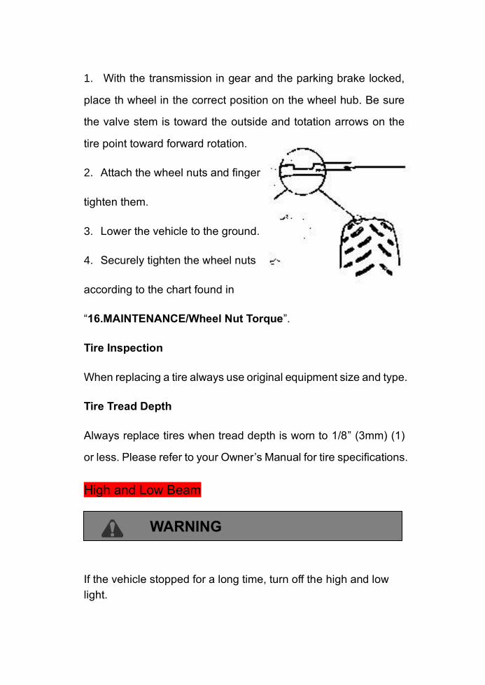
1. With the transmission in gear and the parking brake locked,
place th wheel in the correct position on the wheel hub. Be sure
the valve stem is toward the outside and totation arrows on the
tire point toward forward rotation.
2. Attach the wheel nuts and finger
tighten them.
3. Lower the vehicle to the ground.
4. Securely tighten the wheel nuts
according to the chart found in
“16.MAINTENANCE/Wheel Nut Torque”.
Tire Inspection
When replacing a tire always use original equipment size and type.
Tire Tread Depth
Always replace tires when tread depth is worn to 1/8” (3mm) (1)
or less. Please refer to your Owner’s Manual for tire specifications.
High and Low Beam
WARNING
If the vehicle stopped for a long time, turn off the high and low
light.

16. MAINTENANCE
Headlight Lamp Replacement
WARNING
Keep your headlights and taillights clean. Poor light while riding
can result in an accident causing severe injury or death.
CAUTION
Do not service while headlight is hot. Serious burns may result.
Do not touch a halogen lamp with bare fingers. Oil from your skin
leaves a residue, causing a hot spot which will shorten the life of
the lamp.
16. MAINTENANCE
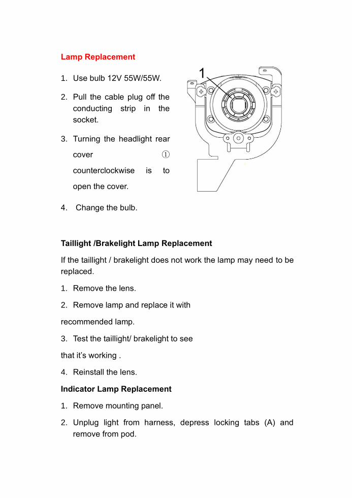
Lamp Replacement
1. Use bulb 12V 55W/55W.
2. Pull the cable plug off the
conducting strip in the
socket.
3. Turning the headlight rear
cover ①
counterclockwise is to
open the cover.
4. Change the bulb.
Taillight /Brakelight Lamp Replacement
If the taillight / brakelight does not work the lamp may need to be
replaced.
1. Remove the lens.
2. Remove lamp and replace it with
recommended lamp.
3. Test the taillight/ brakelight to see
that it’s working .
4. Reinstall the lens.
Indicator Lamp Replacement
1. Remove mounting panel.
2. Unplug light from harness, depress locking tabs (A) and
remove from pod.

3. Install new light and reassemble panel.
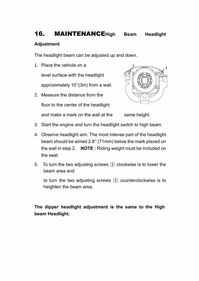
16. MAINTENANCEHigh Beam Headlight
Adjustment
The headlight beam can be adjusted up and down.
1. Place the vehicle on a
level surface with the headlight
approximately 10’’(3m) from a wall.
2. Measure the distance from the
floor to the center of the headlight
and make a mark on the wall at the same height.
3. Start the engine and turn the headlight switch to high beam.
4. Observe headlight aim. The most intense part of the headlight
beam should be aimed 2.8’’ (71mm) below the mark placed on
the wall in step 2. NOTE : Riding weight must be included on
the seat.
5. To turn the two adjusting screws ③ clockwise is to lower the
beam area and
to turn the two adjusting screws ③ counterclockwise is to
heighten the beam area.
The dipper headlight adjustment is the same to the High
beam Headlight.
16. MAINTENANCE
Cleaning Your ATV
Keeping your ATV clean will extend the life of various components.
Washing
Never use a high pressure type car wash system, it can damage
to the wheel bearings, transmission seals, body panels, brakes
and warning labels, and water might enter the engine or exhaust
system.
The best and safest way to clean your ATV is with a garden hose
and a pail of mild soap and water. Use a professional type
washing mitten, cleaning the upper body first and lower parts last.
Rinse with water frequently and dry with a chamois to prevent
water spots. NOTE: If warning labels are damaged, contact your
dealer for replacement.
Waxing
Your ATV can be waxed with any non-abrasive automotive paste
wax. Avoid the use of harsh cleaners since they can scratch the
body finish.
CAUTION
Certain products, including insect repellants and chemicals, will
damage plastic surfaces. Care must be taken when using these
products plastic surfaces.
16. MAINTENANCE
Storage Tips
CAUTION
Do not start the engine during the storage period. This will disturb
the protective film created by fogging.
Cleaning——Clean the ATV thoroughly.
Fuel——Turn the fuel valve to “OFF” and drain the carburetor
bowl completely.
Oil Add and Filter Change——Warm the engine and change oil
and filter.
Air Filter/Air Box——Inspect and clean or replace the pre-
cleaner and air filter. Clean the air box and drain the sediment
tube.
Inspect All Fluid Levels——Inspect the following fluid levels and
change if necessary: transmission; brake fluid (change every two
years or as required if fluid looks dark or contaminated).
Fog the Engine——Spray a light oil into the cylinder through the
spark plug hole.
Check and Lubricate Cables/Grease——Inspect all cables and
lubricate.
Battery Maintenance——Remove the battery and add distilled
water as required to the proper level. Do not use tap water which
may contain minerals that reduce battery life. Apply Dielectric
Grease to the terminal bolts and terminals. Charge the battery.
Storage Area/Covers——Set tire pressure and safely support
the ATV with the tires 1-2”(25-50mm) off the ground. Be sure the
storage area is well ventilated. Cover the machine with a ATV
cover.
NOTE: Do not use plastic or coated materials. They do not allow
enough ventilation to prevent condensation, and may promote
corrosion and oxidation.
16. MAINTENANCE
Transporting
Whenever the ATV is to be transported the following measures
should be taken.
1. Turn off the engine and remove the key.
2. Turn the fuel valve to off.
3. Be certain the fuel cap, oil cap, and seat are installed correctly.
4. Always tie the frame of the ATV to the transporting until
securely using suitable straps or rope.
5. Always place the transmission in gear and lock the parking
brake.
17. TROUBLE SHOOTING
Issues of Improper Operation Driven Clutch (CVT) Burning
Possible Causes Solutions
Loading the ATV into a
pickup or tall trailer when in
Shift transmission to Low Range during
loading of the ATV to prevent belt
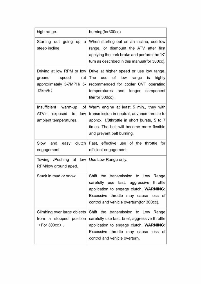
high range. burning(for300cc)
Starting out going up a
steep incline
When starting out on an incline, use low
range, or dismount the ATV after first
applying the park brake and perform the “K”
turn as described in this manual(for 300cc).
Driving at low RPM or low
ground speed (at
approximately 3-7MPH/ 5-
12km/h)
Drive at higher speed or use low range.
The use of low range is highly
recommended for cooler CVT operating
temperatures and longer component
life(for 300cc).
Insufficient warm-up of
ATV’s exposed to low
ambient temperatures.
Warm engine at least 5 min., they with
transmission in neutral, advance throttle to
approx. 1/8throttle in short bursts, 5 to 7
times. The belt will become more flexible
and prevent belt burning.
Slow and easy clutch
engagement.
Fast, effective use of the throttle for
efficient engagement.
Towing /Pushing at low
RPM/low ground aped.
Use Low Range only.
Stuck in mud or snow. Shift the transmission to Low Range
carefully use fast, aggressive throttle
application to engage clutch. WARNING:
Excessive throttle may cause loss of
control and vehicle overturn(for 300cc).
Climbing over large objects
from a stopped position
(For 300cc).
Shift the transmission to Low Range
carefully use fast, brief, aggressive throttle
application to engage clutch. WARNING:
Excessive throttle may cause loss of
control and vehicle overturn.

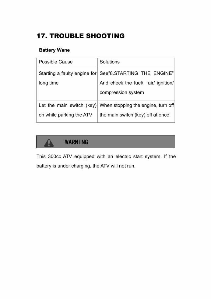
17. TROUBLE SHOOTING
Battery Wane
Possible Cause Solutions
Starting a faulty engine for
long time
See”8.STARTING THE ENGINE”
And check the fuel/ air/ ignition/
compression system
Let the main switch (key)
on while parking the ATV
When stopping the engine, turn off
the main switch (key) off at once
WARNING
This 300cc ATV equipped with an electric start system. If the
battery is under charging, the ATV will not run.
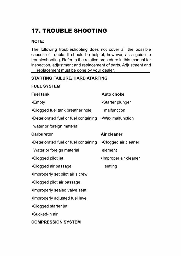
17. TROUBLE SHOOTING
NOTE:
The following troubleshooting does not cover all the possible
causes of trouble. It should be helpful, however, as a guide to
troubleshooting. Refer to the relative procedure in this manual for
inspection, adjustment and replacement of parts. Adjustment and
replacement must be done by your dealer.
STARTING FAILURE/ HARD ATARTING
FUEL SYSTEM
Fuel tank Auto choke
Empty Starter plunger
Clogged fuel tank breather hole malfunction
Deteriorated fuel or fuel containing Wax malfunction
water or foreign material
Carburetor Air cleaner
Deteriorated fuel or fuel containing Clogged air cleaner
Water or foreign material element
Clogged pilot jet Improper air cleaner
Clogged air passage setting
Improperly set pilot air s crew
Clogged pilot air passage
Improperly sealed valve seat
Improperly adjusted fuel level
Clogged starter jet
Sucked-in air
COMPRESSION SYSTEM

Cylinder and cylinder head Valve system
Loose spark plug Improperly adjusted valve
Loose cylinder head clearance
Broken cylinder head gasket Improperly sealed valve
Broken cylinder gasket Improperly contacted
Worn, damaged or seized cylinder valve and vale seat
Piston and Piston ring Improper valve timing
Worn piston Broken valve spring
Worn fatigued or broken piston ring Seized valve
Seized piston ring
Seized or damaged piston
17. TROUBLE SHOOTING
IGNTION SYSTEM
Battery Ignition system
Improperly charged battery Faulty ignitor unit
Faulty battery Faulty pick up coil
Fuse Broken magneto
Burnt out, improper connection woodruff key
Spark plug Switch
Improper plug gap Faulty main switch
Worn electrodes Faulty “ENGINE STOP”
Wire between terminals broken switch
Improper heat range Faulty brake switch
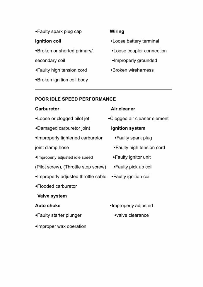
Faulty spark plug cap Wiring
Ignition coil Loose battery terminal
Broken or shorted primary/ Loose coupler connection
secondary coil Improperly grounded
Faulty high tension cord Broken wireharness
Broken ignition coil body
POOR IDLE SPEED PERFORMANCE
Carburetor Air cleaner
Loose or clogged pilot jet Clogged air cleaner element
Damaged carburetor joint Ignition system
Improperly tightened carburetor Faulty spark plug
joint clamp hose Faulty high tension cord
Improperly adjusted idle speed Faulty ignitor unit
(Pilot screw), (Throttle stop screw) Faulty pick up coil
Improperly adjusted throttle cable Faulty ignition coil
Flooded carburetor
Valve system
Auto choke Improperly adjusted
Faulty starter plunger valve clearance
Improper wax operation
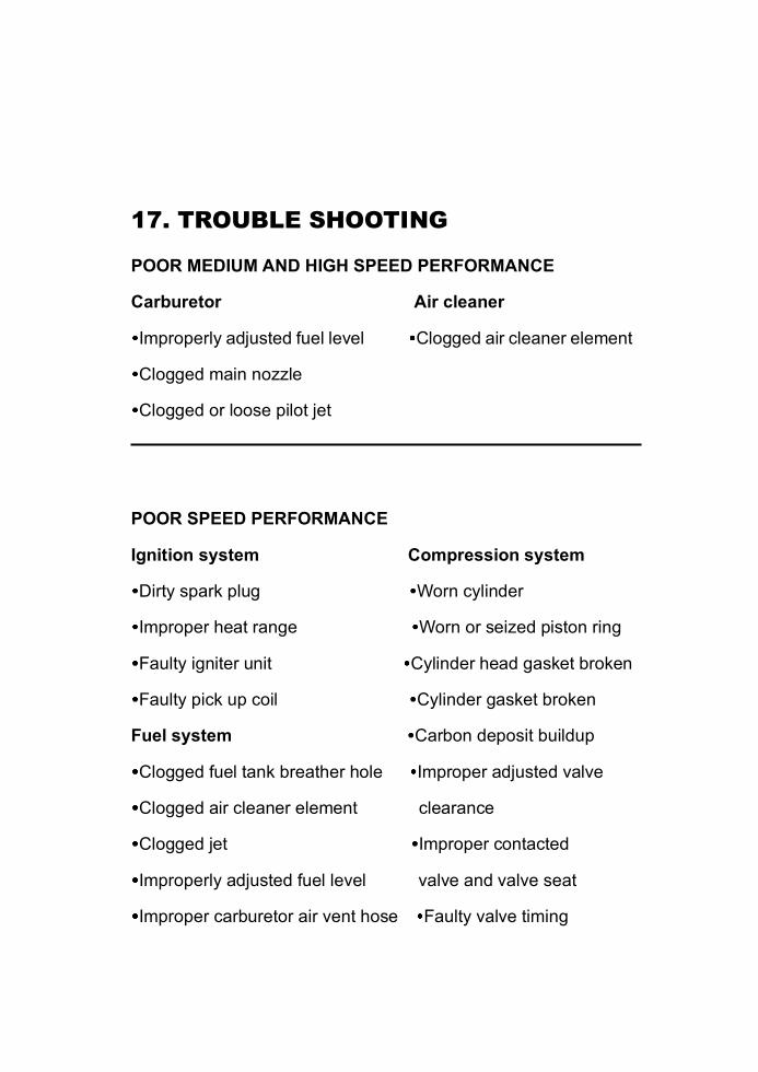
17. TROUBLE SHOOTING
POOR MEDIUM AND HIGH SPEED PERFORMANCE
Carburetor Air cleaner
Improperly adjusted fuel level Clogged air cleaner element
Clogged main nozzle
Clogged or loose pilot jet
POOR SPEED PERFORMANCE
Ignition system Compression system
Dirty spark plug Worn cylinder
Improper heat range Worn or seized piston ring
Faulty igniter unit Cylinder head gasket broken
Faulty pick up coil Cylinder gasket broken
Fuel system Carbon deposit buildup
Clogged fuel tank breather hole Improper adjusted valve
Clogged air cleaner element clearance
Clogged jet Improper contacted
Improperly adjusted fuel level valve and valve seat
Improper carburetor air vent hose Faulty valve timing
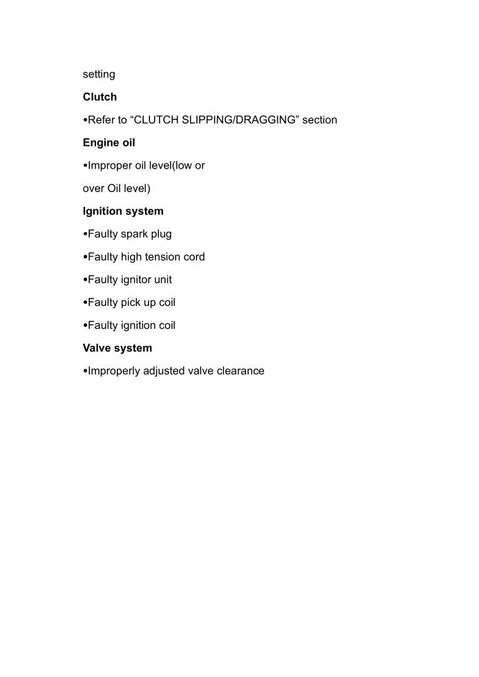
setting
Clutch
Refer to “CLUTCH SLIPPING/DRAGGING” section
Engine oil
Improper oil level(low or
over Oil level)
Ignition system
Faulty spark plug
Faulty high tension cord
Faulty ignitor unit
Faulty pick up coil
Faulty ignition coil
Valve system
Improperly adjusted valve clearance
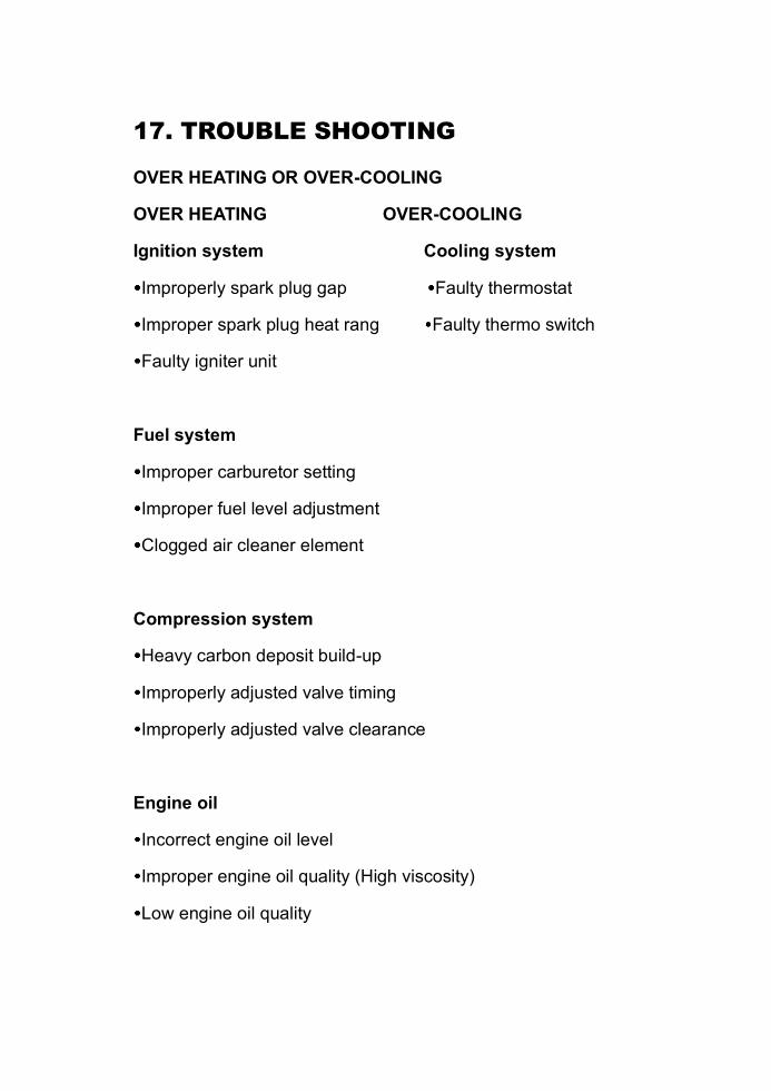
17. TROUBLE SHOOTING
OVER HEATING OR OVER-COOLING
OVER HEATING OVER-COOLING
Ignition system Cooling system
Improperly spark plug gap Faulty thermostat
Improper spark plug heat rang Faulty thermo switch
Faulty igniter unit
Fuel system
Improper carburetor setting
Improper fuel level adjustment
Clogged air cleaner element
Compression system
Heavy carbon deposit build-up
Improperly adjusted valve timing
Improperly adjusted valve clearance
Engine oil
Incorrect engine oil level
Improper engine oil quality (High viscosity)
Low engine oil quality
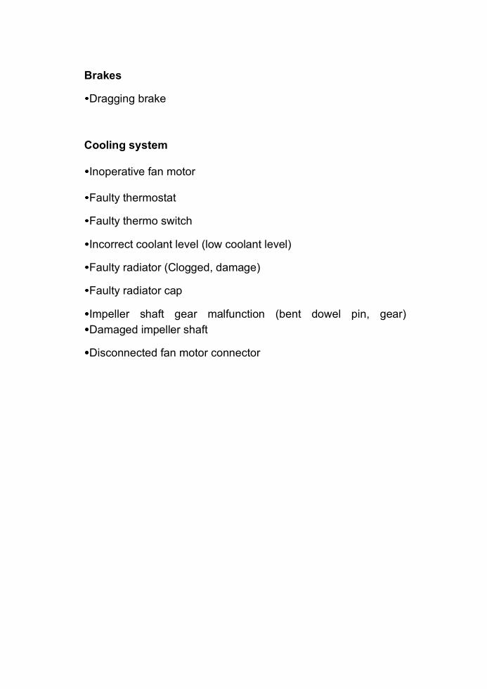
Brakes
Dragging brake
Cooling system
Inoperative fan motor
Faulty thermostat
Faulty thermo switch
Incorrect coolant level (low coolant level)
Faulty radiator (Clogged, damage)
Faulty radiator cap
Impeller shaft gear malfunction (bent dowel pin, gear) Damaged impeller shaft
Disconnected fan motor connector
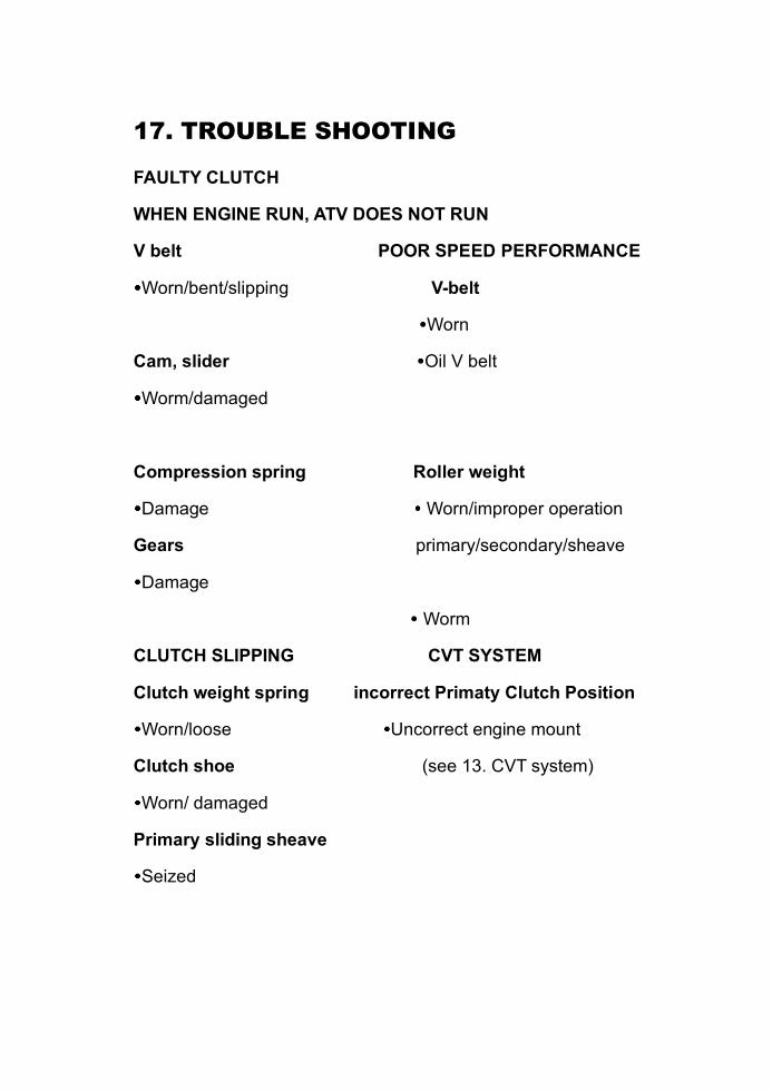
17. TROUBLE SHOOTING
FAULTY CLUTCH
WHEN ENGINE RUN, ATV DOES NOT RUN
V belt POOR SPEED PERFORMANCE
Worn/bent/slipping V-belt
Worn
Cam, slider Oil V belt
Worm/damaged
Compression spring Roller weight
Damage Worn/improper operation
Gears primary/secondary/sheave
Damage
Worm
CLUTCH SLIPPING CVT SYSTEM
Clutch weight spring incorrect Primaty Clutch Position
Worn/loose Uncorrect engine mount
Clutch shoe (see 13. CVT system)
Worn/ damaged
Primary sliding sheave
Seized
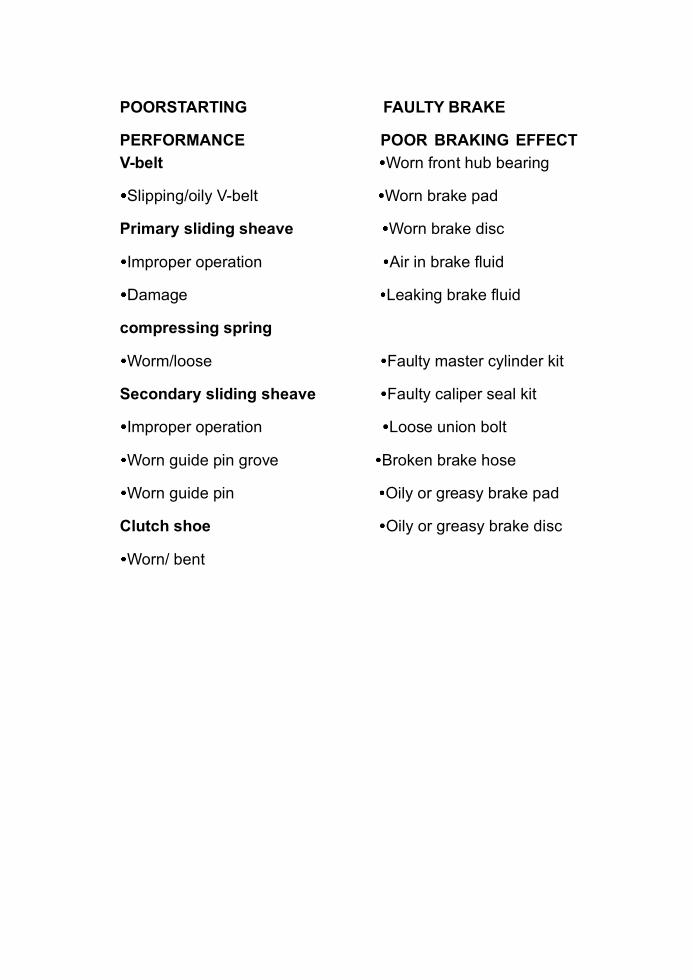
POORSTARTING FAULTY BRAKE
PERFORMANCE POOR BRAKING EFFECT
V-belt Worn front hub bearing
Slipping/oily V-belt Worn brake pad
Primary sliding sheave Worn brake disc
Improper operation Air in brake fluid
Damage Leaking brake fluid
compressing spring
Worm/loose Faulty master cylinder kit
Secondary sliding sheave Faulty caliper seal kit
Improper operation Loose union bolt
Worn guide pin grove Broken brake hose
Worn guide pin Oily or greasy brake pad
Clutch shoe Oily or greasy brake disc
Worn/ bent
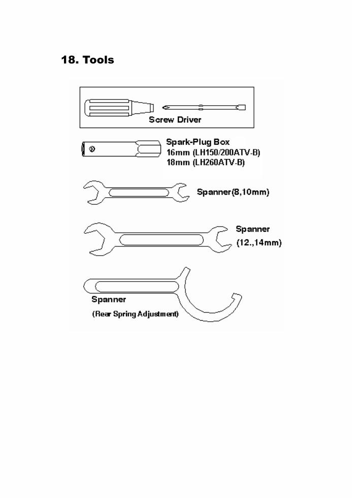
18. Tools
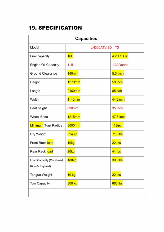
19. SPECIFICATION
Capacities
Model LH300ATV-3D T3
Fuel capacity 16L 4.2U.S.Gal
Engine Oil Capacity 1.4L 1.32Quarts
Ground Clearance 140mm 5.5 inch
Height 1270mm 50 inch
Length 2160mm 85inch
Width 1140mm 44.8inch
Seat height 890mm 35 inch
Wheel Base 1215mm 47.8 inch
Minimum Turn Radius 3000mm 118inch
Dry Weight 324 kg 713 lbs
Front Rack load 10kg 22 lbs
Rear Rack load 20kg 44 lbs
Load Capacity (Combined
Rider& Payload)
180kg 396 lbs
Tongue Weight 10 kg 22 lbs
Tow Capacity 300 kg 660 lbs
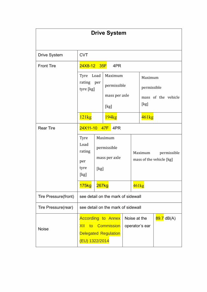
Drive System
Drive System CVT
Front Tire 24X8-12 35F 4PR
Tyre Load
rating per
tyre [kg]
Maximum
permissible
mass per axle
[kg]
Maximum
permissible
mass of the vehicle
[kg]
121kg 194kg 461kg
Rear Tire 24X11-10 47F 4PR
Tyre
Load
rating
per
tyre
[kg]
Maximum
permissible
mass per axle
[kg]
Maximum permissible
mass of the vehicle [kg]
175kg 267kg 461kg
Tire Pressure(front) see detail on the mark of sidewall
Tire Pressure(rear) see detail on the mark of sidewall
Noise
According to Annex
XII to Commission
Delegated Regulation
(EU) 1322/2014
Noise at the
operator’s ear
89.7 dB(A)
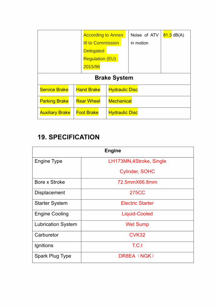
According to Annex
III to Commission
Delegated
Regulation (EU)
2015/96
Noise of ATV
in motion
81.3 dB(A)
Brake System
Service Brake Hand Brake Hydraulic Disc
Parking Brake Rear Wheel Mechanical
Auxiliary Brake Foot Brake Hydraulic Disc
19. SPECIFICATION
Engine
Engine Type LH173MN,4Stroke, Single
Cylinder, SOHC
Bore x Stroke 72.5mmX66.8mm
Displacement 275CC
Starter System Electric Starter
Engine Cooling Liquid-Cooled
Lubrication System Wet Sump
Carburetor CVK32
Ignitions T.C.I
Spark Plug Type DR8EA(NGK)

Electrical Equipment
300cc
Battery 12V 14AH
Front High Beam 12V 55Wx2
Front Dipped Headlight 12V 55WX2
Brake/ Tail Light 12VLed X 2
Front Flasher Light 12V 21W X 2
Rear Flasher Light 12VLed X 2
Mark Light 12V 5W
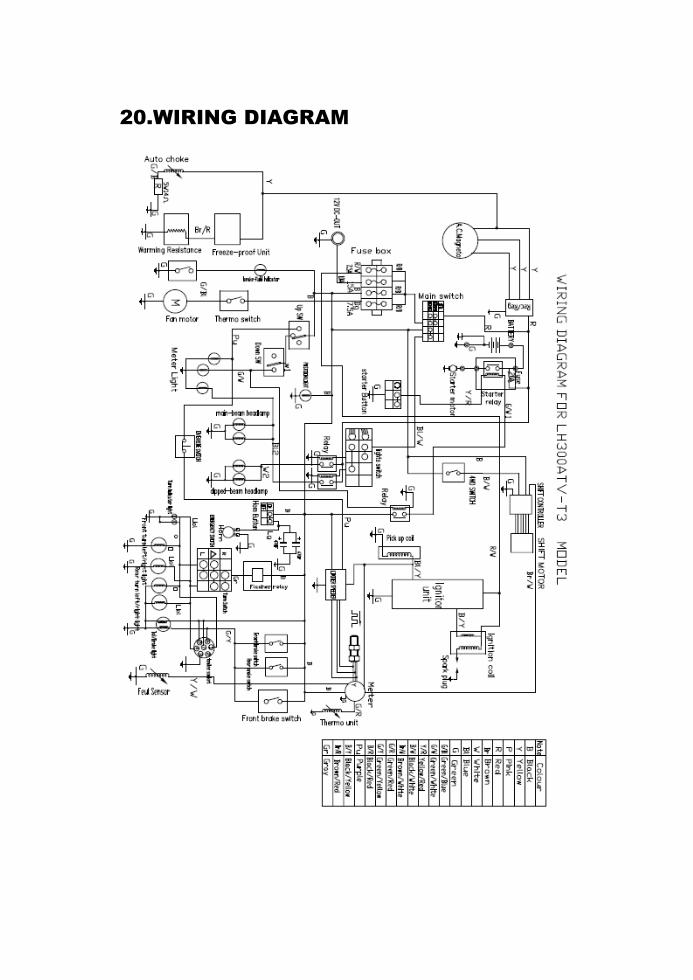
20.WIRING DIAGRAM