![[Standard] X-Axis Cross Roller [High Precision] X-Axis ...1 -1917 1 -1918 [Standard] X-Axis Cross Roller [High Precision] X-Axis Cross Roller Micrometer Head QFeatures: High precision](https://static.fdocuments.net/doc/165x107/60c3f4ceb8f77b61ab46ed07/standard-x-axis-cross-roller-high-precision-x-axis-1-1917-1-1918-standard.jpg)
Cross-Roller Ring Series
28
Cross-Roller Ring Series Compact, Highly Rigid Swivel Bearings Achieving a Superb Rotation Accuracy CATALOG No.382-3E For details, visit THK at www.thk.com *Product information is updated regularly on the THK website.
Transcript of Cross-Roller Ring Series

Cross-Roller Ring SeriesCompact, Highly Rigid Swivel BearingsAchieving a Superb Rotation Accuracy
CATALOG No.382-3E
For details, visit THK at www.thk.com*Product information is updated regularly on the THK website.

1
Contents▼Cross-Roller Ring Series
Structure and Features .............. P.2-3
Types and Features........................ P.4
Selection.......................................... P.5
Rated Life ........................................ P.5
Static Safety Factor ........................ P.6
Static Permissible Moment............ P.6
Static Permissible Axial Load ...... P.6
Accuracy Standards...................... P.7-
Radial Clearance .......................... P.12
Fit .................................................. P.13
Designing the Housing and the Presser Flange .... P.14-15
Installation Procedure.................. P.15
Examples of Model Number Coding...... P.16
Dimensional Tables Model RU .............. P.17-18
Model RB .............. P.19-20
Model RE .............. P.21-23
USP Grade Series of Models RB/RE .... P.24
Model RA .............. P.25-26

2
Cross-Roller RingOuter ring
Roller
Spacer retainer
Inner ring
Structure of the Cross-Roller Ring Model RB
● High Rotation AccuracyThe spacer retainer fitting among cross-arrayed rollersprevents rollers from skewing and the rotation torque fromincreasing due to fr ict ion between rollers. Unlikeconventional types using steel sheet retainers, the Cross-Roller Ring does not cause displacement or locking ofrollers and provides a stable rotation torque.Since the inner and outer rings are designed to beseparable, the bearing clearance can be adjusted. Inaddition, highly accurate rotary motion is ensured throughadjusting the bearing clearance to provide a preload.
● Easy HandlingThe inner and outer rings, which are separable, aresecured to the Cross-Roller Ring body after the rollers andspacer retainers are installed. This procedure prevents therings from separating from each other. Thus, it is easy tohandle the rings when installing the Cross-Roller Ring.
● Skewing PreventionThe spacer retainer keeps rollers in their proper position,thereby preventing them from skewing. This eliminatesfriction between rollers, and therefore secures a stablerotation torque.
With the Cross-Roller Ring, cylindrical rollers are arranged crosswise, with each roller perpendicular tothe adjacent roller, in a 90 V゚ groove, separated from each other by a spacer retainer. This designallows just one bearing to receive loads in all directions including, radial, axial and moment loads.Since the Cross-Roller Ring achieves high rigidity despite the minimum possible dimensions of the innerand outer rings, it is optimal for applications such as joints and swiveling units of industrial robots,swiveling tables of machining centers, rotary units of manipulators, precision rotary tables, medicalequipment, measuring instruments and IC manufacturing machines.
Roller Spacer retainer

3
● Significantly Increased Rigidity (Three to Four times Greater)Unlike the thin angular ball bearings installed in double rows, the cross array of rollers allows a single Cross-Roller Ring unit toreceive loads in all directions, increasing the rigidity to three to four times greater than the conventional type.
Moment: M
Double-row angular bearing
Model RA5008 Model RB5013
M (moment)
M (moment)M (moment)
Gradient angle: rad
Moment Rigidity Diagram
Cross-Roller Ring Angular ball bearing
×10-410
9
8
7
6
5
4
3
2
1
0 9.8 19.6 29.4 39.2( N・ m)
RA5008
RB5013
15.876
7.938
8
815
13
φ50 φ50 φ50.8
● Large Load Capacity(1) Compared with the conventional steel sheet retainers, the spacer retainer allows a longer effective contact length of each roller,
thus significantly increasing the load capacity.The spacer retainer guides rollers by holding them over the entire length of each roller, whereas the conventional type of retainersupports them only at a point in the center of each roller. Such one-point contact cannot sufficiently prevent skewing.
(2) In conventional types, the loaded areas are asymmetrical between the outer-ring and the inner-ring sides around theroller longitudinal axis. The greater the applied load, the greater the moment becomes, thus causing end-face contact to occur.This creates frictional resistance, which hinders smooth rotation and quickens wear.
Roller contact length
2
1
1
2
1> 2
With a spacer retainer With a steel sheet retainer (conventional type)
End-face contactLoaded area Loaded area
Symmetrical loaded areasDesign with a spacer retainer
Asymmetrical loaded areasDesign with a steel sheet retainer (conventional type)

4
Model RA (Separable Outer RingType for Inner Ring Rotation)Based on model RB, this model is a light and compact type with thethinnest possible inner and outer rings. It is optimal for locationswhere weight reduction and downsizing are required, such as thehand swiveling unit of robots and manipulators.
Model RA-C (Single-Split Type)The major dimensions of this model are the same as that ofmodel RA. Since the outer ring is split at one point to increase therigidity of the outer ring, this model can also be used for outerring rotation.
Model RB (Separable Outer RingType for Inner Ring Rotation)Being the basic model of the Cross-Roller Ring, its outer ring isseparable while the inner ring is integrated with the main body. Thismodel is used in locations where the rotation accuracy of theinner ring is required. Major applications include the index tableswiveling unit of machine tools.
Model RE (Separable Inner RingType for Outer Ring Rotation)Having the same major dimensions as model RB, this model is usedin locations where the rotation accuracy of the outer ring isrequired.
USP-Grade Series of ModelsRB/REThe rotation accuracy of the USP-Grade Series achieves theultra precision grade that surpasses the world’s highest accuracystandards, such as JIS Class 2, ISO Class 2, DIN P2 andAFBMA ABEC9.
Model RU (Integrated Inner/OuterRing Type)Since the mounting holes are provided, this model does notrequire a presser flange or housing. In addition, because it has anintegrated inner/outer ring structure and is equipped withwashers, its performance is minimally affected by the mountingprocedure, ensuring stable rotation accuracy and torque.This model can be used for both inner-ring rotation and outer-ringrotation.
Cross-Roller Ring OutlineCross-Roller Ring Product Overview

5
Selection of a Cross-Roller RingThe following diagram shows a typical procedure for selecting a Cross-Roller Ring.
Rated LifeThe service life of a Cross-Roller Ring is obtained from the following equation.
Estimating the service life
● Selecting a bearing size Rigidity● Clearance● Rigidity of the
mounting sectionAccuracy ● Accuracy grade
● Inner ring rotation --- model RB
● Outer ring rotation --- model RE
● Mounting space --- models RA and RA-C
Determining the service conditions
Selecting a type
Rotational torque
Lubrication method
L :Rated life(The total number of revolutions that 90% of agroup of identical Cross-Roller Ring unitsindependently operating under the sameconditions can achieve without showingflaking from rolling fatigue)
C :Basic dynamic load rating* (N)PC :Dynamic equivalent radial load (N)fT :Temperature factor (see Fig. 1)fW :Load factor (see Table 1)*Note: The basic dynamic load rating (C) of the
Cross-Roller Ring indicates the radial loadwith constant direction and magnitude, underwhich the rated life (L) is 1 million revolutionswhen a group of identical Cross-Roller Ringunits independently operate under the sameconditions. The basic dynamic load rating (C) isindicated in the dimensional table.
L = 106fT·CfW·PC
103
PC :Dynamic equivalent radial load (N)Fr :Radial load (N)Fa :Axial load (N)M :Moment (N-mm)X :Dynamic radial factor (see Table 2)Y :Dynamic axial factor (see Table 2)dp :Roller pitch circle diameter (mm)
PC = X · Fr + + Y·Fa2Mdp
Moment (M)
Moment (M)
Axial load (Fa)
Radial load (Fr)
[Dynamic equivalent radial load PC]The dynamic equivalent radial load of the Cross-Roller Ring is
obtained from the following equation.
Service condition fW
Smooth motion without impact 1 to 1.2
Normal motion 1.2 to 1.5
Motion with severe impact 1.5 to 3
Note: The normal service temperature is 80℃ or below. If theproduct is to be used at a higher temperature, contact THK.
Fig. 1 Temperature Factor (fT)
Table 1 Load Factor (fW)
Classification X Y
1 0.45
0.67 0.67
Table 2 Dynamic Radial Factor and Dynamic Axial Factor
●If Fr = 0 N and M = 0 N-mm, perform calculation assumingthat X = 0.67 and Y = 0.67.●For service life calculation with a preload taken into
account, contact THK.
≦ 1.5Fr + 2M/dp
Fa
> 1.5Fr + 2M/dp
Fa
Temperature of the bearing unit (℃)
Temperature factor fT 1.0
0.90.80.70.60.5
100 150 200 250
Fig. 2
6
CROSS ROLLER RING OUTLINECross-Roller Ring Product Overview
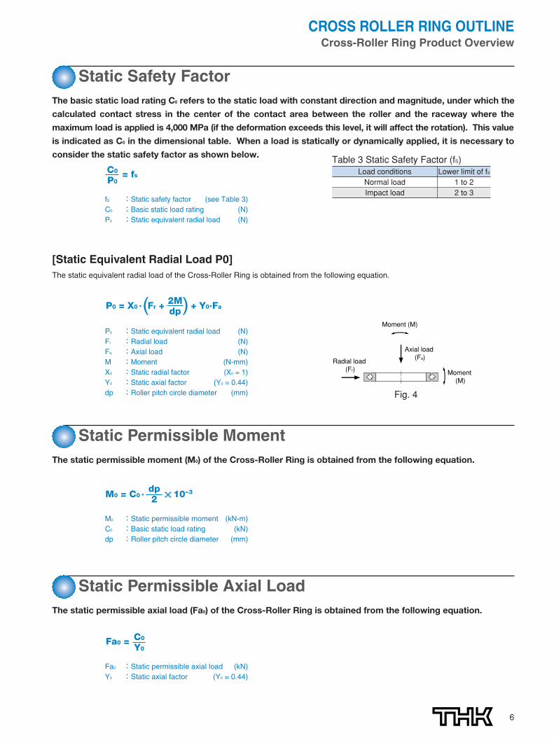
Static Safety FactorThe basic static load rating C0 refers to the static load with constant direction and magnitude, under which the
calculated contact stress in the center of the contact area between the roller and the raceway where the
maximum load is applied is 4,000 MPa (if the deformation exceeds this level, it will affect the rotation). This value
is indicated as C0 in the dimensional table. When a load is statically or dynamically applied, it is necessary to
consider the static safety factor as shown below.
[Static Equivalent Radial Load P0]The static equivalent radial load of the Cross-Roller Ring is obtained from the following equation.
Table 3 Static Safety Factor (fS)Load conditions Lower limit of fSNormal load 1 to 2Impact load 2 to 3
fS :Static safety factor (see Table 3)C0 :Basic static load rating (N)P0 :Static equivalent radial load (N)
C0
P0= fs
Static Permissible MomentThe static permissible moment (M0) of the Cross-Roller Ring is obtained from the following equation.
P0 :Static equivalent radial load (N)Fr :Radial load (N)Fa :Axial load (N)M :Moment (N-mm)X0 :Static radial factor (X0 = 1)Y0 :Static axial factor (Y0 = 0.44)dp :Roller pitch circle diameter (mm)
P0 = X0 · Fr + + Y0·Fa2Mdp
Moment (M)
Moment (M)
Axial load (Fa)Radial load
(Fr)
M0 :Static permissible moment (kN-m)C0 :Basic static load rating (kN)dp :Roller pitch circle diameter (mm)
M0 = C0 · 10–3dp2
Static Permissible Axial LoadThe static permissible axial load (Fa0) of the Cross-Roller Ring is obtained from the following equation.
Fa0 :Static permissible axial load (kN)Y0 :Static axial factor (Y0 = 0.44)
Fa0 = C0
Y0
Fig. 4

7
Accuracy StandardsThe Cross-Roller Ring is manufactured with the accuracy and the dimensional tolerance showing in the Tables 4 to 13.
Table 4 Rotation Accuracy of the Inner Ring of Model RU Unit: μm
Radial runout tolerance of the inner ring Axial runout tolerance of the inner ringModel number
Grade P5 Grade P4 Grade P2 Grade P5 Grade P4 Grade P2
RU 42 4 3 2.5 4 3 2.5RU 66 5 4 2.5 5 4 2.5RU 85 5 4 2.5 5 4 2.5RU124 5 4 2.5 5 4 2.5RU148 6 5 2.5 6 5 2.5RU178 6 5 2.5 6 5 2.5RU228 8 6 5 8 6 5RU297 10 8 5 10 8 5RU445 15 12 7 15 12 7
Table 5 Rotation Accuracy of the Outer Ring of Model RU Unit: μm
Radial runout tolerance of the outer ring Axial runout tolerance of the outer ringModel number
Grade P5 Grade P4 Grade P2 Grade P5 Grade P4 Grade P2
RU 42 8 5 4 8 5 4RU 66 10 6 5 10 6 5RU 85 10 6 5 10 6 5RU124 13 8 5 13 8 5RU148 15 10 7 15 10 7RU178 15 10 7 15 10 7RU228 18 11 7 18 11 7RU297 20 13 8 20 13 8RU445 25 16 10 25 16 10
Note: The standard rotation accuracy of model RU is grade P5 (not expressed in the model number).
Note: The standard rotation accuracy of model RU is grade P5 (not expressed in the model number).

8
CROSS ROLLER RING OUTLINECross-Roller Ring Product Overview
Table 6 Rotation Accuracy of the Inner Ring of Model RB Unit: μm
Nominal dimension of the Radial runout tolerance of the inner ring Axial runout tolerance of the inner ringbearing inner diameter (d) (mm)
Grade 0Grade PE6 Grade PE5 Grade PE4 Grade PE2
Grade 0Grade PE6 Grade PE5 Grade PE4 Grade PE2
Above Or less Grade P6 Grade P5 Grade P4 Grade P2 Grade P6 Grade P5 Grade P4 Grade P218 30 13 8 4 3 2.5 13 8 4 3 2.530 50 15 10 5 4 2.5 15 10 5 4 2.550 80 20 10 5 4 2.5 20 10 5 4 2.580 120 25 13 6 5 2.5 25 13 6 5 2.5120 150 30 18 8 6 2.5 30 18 8 6 2.5150 180 30 18 8 6 5 30 18 8 6 5180 250 40 20 10 8 5 40 20 10 8 5250 315 50 25 13 10 ― 50 25 13 10 ―315 400 60 30 15 12 ― 60 30 15 12 ―400 500 65 35 18 14 ― 65 35 18 14 ―500 630 70 40 20 16 ― 70 40 20 16 ―630 800 80 ― ― ― ― 80 ― ― ― ―800 1000 90 ― ― ― ― 90 ― ― ― ―1000 1250 100 ― ― ― ― 100 ― ― ― ―
Table 8 Rotation Accuracy of the Inner Ring of Models RA and RA-C Unit: μm
Nominal dimension of the Tolerance bearing inner diameter (d) (mm) in radial/Above Or less axial runout40 65 1365 80 1580 100 15100 120 20120 140 25140 180 25180 200 30
Table 9 Rotation Accuracy of the Outer Ring of Model RA-C Unit: μm
Nominal dimension of the Tolerance bearing outer diameter (D) (mm) in radial/Above Or less axial runout65 80 1380 100 15100 120 15120 140 20140 180 25180 200 25200 250 30
Table 7 Rotation Accuracy of the Outer Ring of Model RE Unit: μm
Nominal dimension of the Radial runout tolerance of the outer ring Axial runout tolerance of the outer ringbearing outer diameter (D) (mm)
Grade 0Grade PE6 Grade PE5 Grade PE4 Grade PE2
Grade 0Grade PE6 Grade PE5 Grade PE4 Grade PE2
Above Or less Grade P6 Grade P5 Grade P4 Grade P2 Grade P6 Grade P5 Grade P4 Grade P230 50 20 10 7 5 2.5 20 10 7 5 2.550 80 25 13 8 5 4 25 13 8 5 480 120 35 18 10 6 5 35 18 10 6 5120 150 40 20 11 7 5 40 20 11 7 5150 180 45 23 13 8 5 45 23 13 8 5180 250 50 25 15 10 7 50 25 15 10 7250 315 60 30 18 11 7 60 30 18 11 7315 400 70 35 20 13 8 70 35 20 13 8400 500 80 40 23 15 ― 80 40 23 15 ―500 630 100 50 25 16 ― 100 50 25 16 ―630 800 120 60 30 20 ― 120 60 30 20 ―800 1000 120 75 ― ― ― 120 75 ― ― ―1000 1250 120 ― ― ― ― 120 ― ― ― ―1250 1600 120 ― ― ― ― 120 ― ― ― ―
Note: The rotation accuracy of the outer ring for model RA-C indicates the valuebefore separation.
Note: If higher accuracy than the above values is required for the inner ring inrotation accuracy for models RA and RA-C, contact THK.

9
Note 1: The standard inner diameter accuracy of models RA, RA-C and RU is grade 0. For higher accuracy than grade 0, contact THK.Note 2: “dm” represents the arithmetic average of the maximum and minimum diameters obtained in measuring the bearing inner diameter at two points.Note 3: For accuracy grades of the bearing inner diameter with no values indicated in the table, the highest value among the low accuracy grades applies.
Table 10 Dimensional Tolerance of the Bearing Inner Diameter Unit: μm
Nominal dimension of the Tolerance of dm (see Note 2)
bearing inner diameter (d) (mm) Grades 0, P6, P5, P4 and P2 Grade PE6 Grade PE5 Grades PE4 and PE2Above Or less Upper Lower Upper Lower Upper Lower Upper Lower18 30 0 -10 0 -8 0 -6 0 -530 50 0 -12 0 -10 0 -8 0 -650 80 0 -15 0 -12 0 -9 0 -780 120 0 -20 0 -15 0 -10 0 -8120 150 0 -25 0 -18 0 -13 0 -10150 180 0 -25 0 -18 0 -13 0 -10180 250 0 -30 0 -22 0 -15 0 -12250 315 0 -35 0 -25 0 -18 ― ―315 400 0 -40 0 -30 0 -23 ― ―400 500 0 -45 0 -35 ― ― ― ―500 630 0 -50 0 -40 ― ― ― ―630 800 0 -75 ― ― ― ― ― ―800 1000 0 -100 ― ― ― ― ― ―1000 1250 0 -125 ― ― ― ― ― ―
Note 1: The standard outer diameter accuracy of models RA, RA-C and RU is grade 0. For higher accuracy than grade 0, contact THK.Note 2: “Dm” represents the arithmetic average of the maximum and minimum diameters obtained in measuring the bearing outer diameter at two points.Note 3: For accuracy grades of the bearing outer diameter with no values indicated in the table, the highest value among the low accuracy grades applies.
Table 11 Dimensional Tolerance of the Bearing Outer Diameter Unit: μm
Nominal dimension of the Tolerance of Dm (see Note 2)
bearing outer diameter (D) (mm) Grades 0, P6, P5, P4 and P2 Grade PE6 Grade PE5 Grades PE4 and PE2Above Or less Upper Lower Upper Lower Upper Lower Upper Lower30 50 0 -11 0 -9 0 -7 0 -650 80 0 -13 0 -11 0 -9 0 -780 120 0 -15 0 -13 0 -10 0 -8120 150 0 -18 0 -15 0 -11 0 -9150 180 0 -25 0 -18 0 -13 0 -10180 250 0 -30 0 -20 0 -15 0 -11250 315 0 -35 0 -25 0 -18 0 -13315 400 0 -40 0 -28 0 -20 0 -15400 500 0 -45 0 -33 0 -23 ― ―500 630 0 -50 0 -38 0 -28 ― ―630 800 0 -75 0 -45 0 -35 ― ―800 1000 0 -100 ― ― ― ― ― ―1000 1250 0 -125 ― ― ― ― ― ―1250 1600 0 -160 ― ― ― ― ― ―

10
CROSS ROLLER RING OUTLINECross-Roller Ring Product Overview
Note: All B and B1 steps of models RA and RA-C are manufactured with tolerance between -0.120 and 0.
Table 13 Tolerance of the Inner/Outer Ring Width of Models RB and RE (Common to All Grades) Unit: μm
Nominal dimension of the bearing inner diameter (d) (mm)Tolerance of B Tolerance of B1
Applied to the inner ring of model RB and the outer ring of model RE Applied to the outer ring of model RB and the inner ring of model REAbove Or less Upper Lower Upper Lower18 30 0 -75 0 -10030 50 0 -75 0 -10050 80 0 -75 0 -10080 120 0 -75 0 -100120 150 0 -100 0 -120150 180 0 -100 0 -120180 250 0 -100 0 -120250 315 0 -120 0 -150315 400 0 -150 0 -200400 500 0 -150 0 -200500 630 0 -150 0 -200630 800 0 -150 0 -200800 1000 0 -300 0 -4001000 1250 0 -300 0 -400
Table 12 Tolerance of the Inner/Outer Ring Width of Model RU Unit: μm
Model numberTolerance of B
Upper LowerRU 42 0 -75RU 66 0 -75RU 85 0 -75RU124 0 -75RU148 0 -75RU178 0 -100RU228 0 -100RU297 0 -100RU445 0 -150

11
Accuracy Standards for the USP Series
[Example of Rotation Accuracy of the USP Series]The rotation accuracy of the USP-Grade Series achieves the ultra precision grade that surpasses the world’s highest accuracy
standards, such as JIS Class 2, ISO Class 2, DIN P2 and AFBMA ABEC9.
[Accuracy Standards for the USP Series]The USP-Grade Series of the Cross-Roller Ring models RU, RB and RE are manufactured with the accuracy and the dimensional
tolerance showing in Tables 14 and 15.
Rotation accuracy of the inner ring of model RB50040CC0USP
Rotation accuracy of the outer ring of model RE50040CC0USP
Radial runout
(specification: 5 μm max)
Axial runout
(specification: 5 μm max)
2μm 2.5μm
φ 500
40
φ 600
Radial runout
(specification: 7 μm max)
Axial runout
(specification: 7 μm max)
2.5μm
3μm
φ 500
40
φ 600
Table 14 Runout Accuracy of the USP-Grade Series of Models RB and RE Unit: μm
Runout accuracy of the Runout accuracy of theinner ring of model RB outer ring of model RE
Above Or lessRadial runout Axial runout Radial runout Axial runouttolerance tolerance tolerance tolerance
80 180 2.5 2.5 3 3180 250 3 3 4 4250 315 4 4 4 4315 400 4 4 5 5400 500 5 5 5 5500 630 6 6 7 7630 800 ― ― 8 8
Table 15 Runout Accuracy of the USP-Grade Series of Model RU Unit: μm
Runout accuracy of the Runout accuracy of the
Model numberinner ring of model RU outer ring of model RURadial runout Axial runout Radial runout Axial runouttolerance tolerance tolerance tolerance
RU 42 2 2 3 3RU 66 2 2 3 3RU 85 2 2 3 3RU124 2 2 3 3RU148 2 2 4 4RU178 2 2 4 4RU228 2.5 2.5 4 4RU297 3 3 5 5RU445 4 4 7 7
Nominal dimension of theinner diameter (d) andouter diameter (D) (mm)
12
CROSS ROLLER RING OUTLINECross-Roller Ring Product Overview
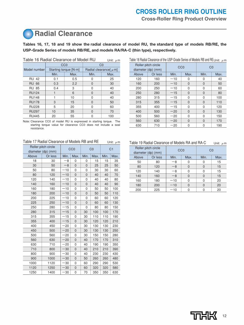
Radial ClearanceTables 16, 17, 18 and 19 show the radial clearance of model RU, the standard type of models RB/RE, the
USP-Grade Series of models RB/RE, and models RA/RA-C (thin type), respectively.
Note: Clearance CC0 of model RU is expressed in starting torque. Thestarting torque value for clearance CC0 does not include a sealresistance.
Table 17 Radial Clearance of Models RB and RE Unit: μm
Roller pitch circleCC0 C0 C1
diameter (dp) (mm)Above Or less Min. Max. Min. Max. Min. Max.18 30 -8 0 0 15 15 3530 50 -8 0 0 25 25 5050 80 -10 0 0 30 30 6080 120 -10 0 0 40 40 70120 140 -10 0 0 40 40 80140 160 -10 0 0 40 40 90160 180 -10 0 0 50 50 100180 200 -10 0 0 50 50 110200 225 -10 0 0 60 60 120225 250 -10 0 0 60 60 130250 280 -15 0 0 80 80 150280 315 -15 0 30 100 100 170315 355 -15 0 30 110 110 190355 400 -15 0 30 120 120 210400 450 -20 0 30 130 130 230450 500 -20 0 30 130 130 250500 560 -20 0 30 150 150 280560 630 -20 0 40 170 170 310630 710 -20 0 40 190 190 350710 800 -30 0 40 210 210 390800 900 -30 0 40 230 230 430900 1000 -30 0 50 260 260 4801000 1120 -30 0 60 290 290 5301120 1250 -30 0 60 320 320 5801250 1400 -30 0 70 350 350 630
Table 18 Radial Clearance of the USP-Grade Series of Models RB and REUnit: μmRoller pitch circle
CC0 C0diameter (dp) (mm)Above Or less Min. Max. Min. Max.120 160 -10 0 0 40160 200 -10 0 0 50200 250 -10 0 0 60250 280 -15 0 0 80280 315 -15 0 0 100315 355 -15 0 0 110355 400 -15 0 0 120400 500 -20 0 0 130500 560 -20 0 0 150560 630 -20 0 0 170630 710 -20 0 0 190
Table 19 Radial Clearance of Models RA and RA-C Unit: μm
Roller pitch circleCC0 C0
diameter (dp) (mm)Above Or less Min. Max. Min. Max.50 80 -8 0 0 1580 120 -8 0 0 15120 140 -8 0 0 15140 160 -8 0 0 15160 180 -10 0 0 20180 200 -10 0 0 20200 225 -10 0 0 20
Table 16 Radial Clearance of Model RU Unit: μm
CC0 C0Model number Starting torque [N-m] Radial clearance[μm]
Min. Max. Min. Max.RU 42 0.1 0.5 0 25RU 66 0.3 2.2 0 30RU 85 0.4 3 0 40RU124 1 6 0 40RU148 1 10 0 40RU178 3 15 0 50RU228 5 20 0 60RU297 10 35 0 70RU445 20 55 0 100

13
Fit
[Fit for Models RB, RE and RA]For the fit for models RB, RE and RA, we recommend using the combinations indicated in Table 20.
[Fit for Model RU]Model RU does not require a fit in principle. However, if a certain level of positioning accuracy is required, h7 and H7 are
recommended for the fit.
[Fit for Model RA-C]For the fit for model RA-C, we recommend using the combinations indicated in Table 22.
[Fit for the USP-Grade Series]For the fit for the USP-Grade Series of models RB and RE, we recommend using the combinations indicated in Table 21.
Note: For the fit for clearance CC0, avoid an interference because it will cause an excessive preload. As for the fit when you have selected clearance CC0 for thejoints or swiveling unit of a robot, the combination of g5 and H7 is recommended.
Note: We recommend measuring the inner and outer diameters of the bearing and selecting a slightinterference fit that corresponds to the measurement.
Table 20 Fit for Models RB, RE and RARadial clearance Service conditions Shaft Housing
Inner ring rotational loadNormal load h5 H7
C0Large impact/moment h5 H7
Outer ring rotational loadNormal load g5 Js7Large impact/moment g5 Js7
Inner ring rotational loadNormal load j5 H7
C1Large impact/moment k5 Js7
Outer ring rotational loadNormal load g6 Js7Large impact/moment h5 K7
Table 22 Fit for Model RA-CRadial clearance Service conditions Shaft Housing
CC0Inner ring rotational load h5 J7Outer ring rotational load g5 Js7
C0Inner ring rotational load j5 J7Outer ring rotational load g5 K7
Table 21 Fit for the USP-Grade SeriesRadial clearance Service conditions Shaft Housing
CC0Inner ring rotational load h5 J7Outer ring rotational load g5 Js7
C0Inner ring rotational load j5 J7Outer ring rotational load g5 K7

14
CROSS ROLLER RING OUTLINECross-Roller Ring Product Overview
[Housing]When determining the thickness of the housing, at least 60% of the
sectional height of the bearing must be secured as a guide.
● Tapped Through HolesIf tapped through holes for removing the inner or outer ring (Fig.1) are provided, the ring can be removed without causingdamage to the bearing. When removing the outer ring, do notpress the inner ring, or vise versa. For the dimensions of thepresser on the side(s), see the shoulder dimensionsindicated in the dimensional table.
Designing the Housing and the Presser FlangeSince the Cross-Roller Ring is a compact, thin device, special consideration must be given to the rigidity of the
housing and the presser flange.
With types having a separable outer ring, insufficiency in the strength of the housing, the flange or the
presser bolt will result in the inability to evenly hold the inner or outer ring, or will cause deformation of the bearing
when a moment load is applied. Consequently, the contact area of the rollers will become uneven, causing the
bearing’s performance to significantly deteriorate.
[Examples of installation]Fig. 2 shows examples of installing the Cross-Roller Ring.
Fig. 2 Examples of Installation
Tapped through hole
Tapped through hole
T
a. Outer ring rotating in the swiveling unit: An example of mounting the heavy body part after securing the inner and outer rings
of the Cross-Roller Ring
b. Inner ring rotation with the swiveling unit (with seals attached)
c. The inner and outer rings are secured in the same
direction in the swiveling unit (with seals attached)
Fig. 1
T :Housing thicknessD :Outer diameter of the outer ringd :Inner diameter of the inner ring
T = 0.6D – d2
or greater

15
[Presser Flange and Presser Bolt]When determining the thickness of the presser flange (F) or the clearance of the flange section (S), refer to the dimensions
indicated below as a guide. As for the number of presser bolts, the greater the number of bolts, the more stable the system
becomes. As a guide, however, it is advised to select the appropriate number of bolts
indicated in Table 23 and arrange them equidistantly.
F = B×0.5 to B×1.2H = BS = 0.5 mm
Even if the shaft and the housing are composed of a light alloy, it is recommended to select
a steel-based material for the presser flange.
When tightening the presser bolts, firmly secure them using a torque wrench or the like so that they will not loosen.
Table 24 shows tightening torques for the housing and presser flanges composed of typical steel materials with medium hardness.
0-0.1
[Checking the Parts before Installing Them]Thoroughly clean the housing and other parts to be installed, and check to determine if deburring is required.
[Installing the Cross-Roller Ring into the Housing or onto the Shaft]Since the Cross-Roller Ring is a thin-wall bearing type and therefore tends to misalign when it is installed, gradually drive the
product into the housing or onto the shaft by gently hitting it with a plastic hammer while keeping the product horizontal. Taking care,
continue to hammer until it fully contacts the reference surface.
Note: When installing the inner ring, hammer it, and when installing the outer ring, hammer it.
[Attaching the Presser Flange](1) When attaching the presser flange, attach it to the integrated
rotation ring (i.e., inner ring of models RB and RA, or outer ring
of model RE) first.
(2) Place the presser flange onto the Cross-Roller Ring. Rock
the flange several times to match the bolt holes.
(3) Insert the presser bolts into the holes. Manually turn the bolts
and make sure they do not display skewing caused by
misalignment of the holes.
(4) Tighten the presser bolts in three to four steps from light to full
tightening by repeatedly securing the bolts in diagonal order.
When tightening the separable inner or outer ring, slightly
turning the integral outer or inner ring will correct the
dislocation between the ring and the body.
Installation ProcedureWhen installing the Cross-Roller Ring, follow the procedure below.
Fig. 1 Tightening Order
F
B
S
H
Table 23 Number of Presser Bolts and Bolt Sizes Unit: mm
Outer diameter of the outer ring (D)No. of bolts
Bolt size Above Or less (reference)― 100 8 or more M3 to M5100 200 12 or more M4 to M8200 500 16 or more M5 to M12500 ― 24 or more M12 or greater
Table 24 Tightening Torque of the Bolt Unit: N-m
Nominal size of screw Tightening torque Nominal size of screw Tightening torqueM3 2 M10 70M4 4 M12 120M5 9 M16 200M6 14 M20 390M8 30 M22 530

16
CROSS ROLLER RING OUTLINECross-Roller Ring Product Overview
[Example of Model Number Coding for Models RB, RE, RA and RA-C]
[Example of Model Number Coding for Model RU]
Example of Model Number Coding
RB20030 C UU CC0 P2
Seal symbol
No symbol: without a seal
UU: with seal attached on both sides
U: with seal attached on one side
Radial clearance symbol
CC0: negative clearance (preload)
C0: positive clearance
C1: positive clearance (greater than C0)
Accuracy symbol (applicable to models RB and RE only. For accuracy symbols for models RA and RA-C, contact THK.)
No symbol: normal grade (grade 0)
P6: grade 6 rotation accuracy; PE6: grade 6 rotation accuracy + grade 6 dimensional accuracy
P5: grade 5 rotation accuracy; PE5: grade 5 rotation accuracy + grade 5 dimensional accuracy
P4: grade 4 rotation accuracy; PE4: grade 4 rotation accuracy + grade 4 dimensional accuracy
P2: grade 2 rotation accuracy; PE2: grade 2 rotation accuracy + grade 2 dimensional accuracy
USP: USP grade rotation accuracy
Model number
RU124 UU CC0 P2 B G X -N
Symbol for assembly direction of the mounting hole [applicable to models RU124
to RU445 (excluding X type)]
No symbol: counterbore holes of the inner and outer rings face the same direction
G: counterbore holes of the inner and outer rings face opposite directions
Symbol for accuracy-required part
No symbol: inner ring with rotation accuracy
R: outer ring with rotation accuracy
B: Inner and outer rings with rotation accuracy
Accuracy symbol
No symbol: grade 5 rotation accuracy
P4: grade 4 rotation accuracy
P2: grade 2 rotation accuracy
USP: USP grade rotation accuracy
Radial clearance symbol
CC0: negative clearance (preload)
C0: positive clearance
Seal symbol
No symbol: without a seal
UU: with seal attached on both sides
U: with seal attached on one side (counterbore side of the outer ring)
UT: with seal attached on one side (opposite the counterbore side of the outer ring)
Symbol for inner ring hole [applicable to models RU124 to RU445]
No symbol: counterbore hole on the inner ring
X: tapped hole on the inner ring (through hole)
Option symbol
No symbol: no accessory
-N: with grease nipple attached (for the nipple shape, see P.17)
RU42 to RU178: NP3.2×3.5
RU228 to RU445: NP6×5
Model number
Symbol
No symbol: Models RB, RE and RA
C: Model RA-C

17
RU TYPEModel RU (Integrated Inner and Outer Rings)
Shaftdiameter
Model No.
203555
80
90
115
160
210
350
20 70 41.5 12 3.1 0.6 37 47 7.35 8.35 0.2935 95 66 15 3.1 0.6 59 74 17.5 22.3 0.6255 120 85 15 3.1 0.6 79 93 20.3 29.5 1
80 165 124 22 3.1 1 114 134 33.1 50.9 2.6
90 210 147.5 25 3.1 1.5 133 162 49.1 76.8 4.9
115 240 178 28 3.1 1.5 161 195 80.3 135 6.8
160 295 227.5 35 6 2 208 246 104 173 11.4
210 380 297.3 40 6 2.5 272 320 156 281 21.3
350 540 445.4 45 6 2.5 417 473 222 473 35.4
RU 42RU 66RU 85RU 124(G)RU 124XRU 148(G)RU 148XRU 178(G)RU 178XRU 228(G)RU 228XRU 297(G)RU 297XRU 445(G)RU 445X
Major dimensionsShoulderdimensions
Basic load rating(radial)
Innerdiameter
d
Outerdiameter
D
Roller pitch
circlediameter
dp
Width
B
C
kN
C0
kNrmin ds Dh kg
Greasinghole
d1
Mass
For the model number coding, see P.16.
Option
For model RU, a grease nipple is available as an option (see the figure below).
If the grease nipple is required, add“-N”at the end of the model number when placing an order.
B r
r
2-greasing hole
B
2-greasing hole
r
r
RU42-RU85
RU124-RU445
RU124G-RU445G RU124X-RU445X
φ d
φ d
φ D
φ D
Model NP3.2×3.5
95.51.5
6φ 7.5φ
3.1φ
Model NP6×5
1162
6φ 6φ 8φ
Note

18
28 6-M3 through 57 6-φ3.4 through φ6.5 counterbore depth 3.345 8-M4 through 83 8-φ4.5 through φ8 counterbore depth 4.465 8-M5 through 105 8-φ5.5 through φ9.5 counterbore depth 5.4
9710-φ5.5 through φ9.5 counterbore depth 5.4
148 10-φ5.5 through φ9.5 counterbore depth 5.410-M5 through
11212-φ9 through φ14 counterbore depth 8.6
187 12-φ9 through φ14 counterbore depth 8.612-M8 through
13912-φ9 through φ14 counterbore depth 8.6
217 12-φ9 through φ14 counterbore depth 8.612-M8 through
18412-φ11 through φ17.5 counterbore depth 10.8
270 12-φ11 through φ17.5 counterbore depth 10.812-M10 through
24016-φ14 through φ20 counterbore depth 13
350 16-φ14 through φ20 counterbore depth 1316-M12 through
38524-φ14 through φ20 counterbore depth 13
505 24-φ14 through φ20 counterbore depth 1324-M12 through
Unit: mm
RU 42RU 66RU 85RU 124(G)RU 124XRU 148(G)RU 148XRU 178(G)RU 178XRU 228(G)RU 228XRU 297(G)RU 297XRU 445(G)RU 445X
Relation between the mounting holes
Inner ring
PCD1 Mounting hole PCD2 Mounting hole
Outer ringModel No.
Model RU
Model RU…UU
Model RU…U
Model RU…UT
PCD
PCD1
2
φ Dh
φ ds

19
RB TYPEModel RB (Separable Outer Ring Type)
Shaftdiameter
Model No.
2025303540455060708090
100
110
120
130
140
150
160
20 36 27 8 2 0.8 0.5 23.5 30.5 3.23 3.1 0.0425 41 32 8 2 0.8 0.5 28.5 35.5 3.63 3.83 0.0530 55 41.5 10 2.5 1 0.6 37 47 7.35 8.36 0.1235 60 46.5 10 2.5 1 0.6 41 51.5 7.64 9.12 0.1340 65 51.5 10 2.5 1 0.6 47.5 57.5 8.33 10.6 0.1645 70 56.5 10 2.5 1 0.6 51 61.5 8.62 11.3 0.1750 80 64 13 2.5 1.6 0.6 57.4 72 16.7 20.9 0.2760 90 74 13 2.5 1.6 0.6 68 82 18 24.3 0.370 100 84 13 2.5 1.6 0.6 78 92 19.4 27.7 0.3580 120 98 16 3 1.6 0.6 91 111 30.1 42.1 0.790 130 108 16 3 1.6 1 98 118 31.4 45.3 0.75
100140 119.3 16 3.5 1.6 1 109 129 31.7 48.6 0.83150 123 20 3.5 1.6 1 113 133 33.1 50.9 1.45135 121.8 12 2.5 1 0.6 117 127 12.5 24.1 0.4
110 145 126.5 15 3.5 1.6 0.6 122 136 23.7 41.5 0.75160 133 20 3.5 1.6 1 120 143 34 54 1.56
120150 134.2 16 3.5 1.6 0.6 127 141 24.2 43.2 0.72180 148.7 25 3.5 2 1.5 133 164 66.9 100 2.62
130160 144.5 15 3.5 1.6 0.6 137 152 25 46.7 0.72190 158 25 3.5 2 1.5 143 174 69.5 107 2.82
140175 154.8 16 2.5 1.6 1 147 162 25.9 50.1 1200 168 25 3.5 2 1.5 154 185 74.8 121 2.96180 164 13 2.5 1.6 0.6 157 172 27 53.5 0.68
150 210 178 25 3.5 2 1.5 164 194 76.8 128 3.16230 188 30 4.5 3 1.5 173 211 100 156 5.3
160 220 188.6 25 3.5 2 1.5 173 204 81.7 135 3.14
Unit: mm
RB 2008RB 2508RB 3010RB 3510RB 4010RB 4510RB 5013RB 6013RB 7013RB 8016RB 9016RB 10016RB 10020RB 11012RB 11015RB 11020RB 12016RB 12025RB 13015RB 13025RB 14016RB 14025RB 15013RB 15025RB 15030RB 16025
Major dimensionsShoulderdimensions
Basic load rating(radial)
Innerdiameter
d
Outerdiameter
D
Roller pitchcirclediameter
dp
Width
B B1
C
kN
C0
kNa b rmin ds Dh kg
Greasing hole
Mass
Model number of a part with seals attached is RB…UU.If a certain level of accuracy is required, use this model for inner ring rotation.For the model number coding, see P.16.
4-greasing hole
Detail view of the greasing hole
φ d
φ D
B B1
r
r
a
b
φ ds
φ Dh
Note

20
Shaftdiameter
Model No.
170180190
200
220240
250
300
350
400
450
500
600700800900
10001250
170 220 191 20 3.5 1.6 1.5 184 198 29 62.1 2.21180 240 210 25 3.5 2 1.5 195 225 84 143 3.44190 240 211.9 25 3.5 1.6 1 202 222 41.7 82.9 2.99
260 230 25 3.5 2 2 215 245 84.2 157 4200 280 240 30 4.5 3 2 221 258 114 200 6.7
295 247.7 35 5 3 2 225 270 151 252 9.6220 280 250.1 25 3.5 2 2 235 265 92.3 171 4.1240 300 269 25 3.5 2 2.5 256 281 68.3 145 4.5
310 277.5 25 3.5 2 2.5 265 290 69.3 150 5250 330 287.5 30 4.5 3 2.5 269 306 126 244 8.1
355 300.7 40 6 3.5 2.5 275 326 195 348 14.8360 328 25 3.5 2 2.5 315 340 76.3 178 5.9
300 395 345 35 5 3 2.5 322 368 183 367 13.4405 351.6 40 6 3.5 2.5 326 377 212 409 17.2
350 400 373.4 20 3.5 1.6 2.5 363 383 54.1 143 3.9
400480 440.3 35 5 3 2.5 422 459 156 370 14.5510 453.4 40 6 3.5 2.5 428 479 241 531 23.5
450 500 474 25 3.5 1.6 1 464 484 61.7 182 6.6550 524.2 25 3.5 1.6 1 514 534 65.5 201 7.3
500 600 548.8 40 6 3 2.5 526 572 239 607 26625 561.6 50 6 3.5 2.5 536 587 267 653 41.7
600 700 650 40 6 3 3 627 673 264 721 29700 815 753.5 45 6 3 3 731 777 281 836 46800 950 868.1 70 6 4 4 836 900 468 1330 105900 1050 969 70 6 4 4 937 1001 494 1490 120
1000 1250 1114 110 6 6 5 1057 1171 1220 3220 3601250 1500 1365.8 110 6 6 5 1308 1423 1350 3970 440
Unit: mm
RB 17020RB 18025RB 19025RB 20025RB 20030RB 20035RB 22025RB 24025RB 25025RB 25030RB 25040RB 30025RB 30035RB 30040RB 35020RB 40035RB 40040RB 45025RB 50025RB 50040RB 50050RB 60040RB 70045RB 80070RB 90070RB 1000110RB 1250110
Major dimensionsShoulderdimensions
Basic load rating(radial)
Innerdiameter
d
Outerdiameter
D
Roller pitchcirclediameter
dp
Width
B B1
C
kN
C0
kNa b rmin ds Dh kg
Greasing hole
Mass
Model number of a part with seals attached is RB…UU.If a certain level of accuracy is required, use this model for inner ring rotation.For the model number coding, see P.16.
Model RB…UU
Model RB
Note

21
RE TYPEModel RE (Separable Inner Ring Type)
Shaftdiameter
Model No.
2025303540455060708090
100
110
120
130
20 36 29 8 2 0.8 0.5 23.5 30.5 3.23 3.1 0.0425 41 34 8 2 0.8 0.5 28.5 35.5 3.63 3.83 0.0530 55 43.5 10 2.5 1 0.6 37 47 7.35 8.36 0.1235 60 48.5 10 2.5 1 0.6 41 51.5 7.64 9.12 0.1340 65 53.5 10 2.5 1 0.6 47.5 58 8.33 10.6 0.1645 70 58.5 10 2.5 1 0.6 51 61.5 8.62 11.3 0.1750 80 66 13 2.5 1.6 0.6 57.5 72 16.7 20.9 0.2760 90 76 13 2.5 1.6 0.6 68 82 18 24.3 0.370 100 86 13 2.5 1.6 0.6 78 92 19.4 27.7 0.3580 120 101.4 16 3 1.6 0.6 91 111 30.1 42.1 0.790 130 112 16 3 1.6 1 98 118 31.4 45.3 0.75
100140 121.1 16 3 1.6 1 109 129 31.7 48.6 0.83150 127 20 3.5 1.6 1 113 133 33.1 50.9 1.45135 123.3 12 2.5 1 0.6 117 127 12.5 24.1 0.4
110 145 129 15 3 1.6 0.6 122 136 23.7 41.5 0.75160 137 20 3.5 1.6 1 120 140 34 54 1.56
120150 136 16 3 1.6 0.6 127 141 24.2 43.2 0.72180 152 25 3.5 2 1.5 133 164 66.9 100 2.62
130160 146 15 3 1.6 0.6 137 152 25 46.7 0.72190 162 25 3.5 2 1.5 143 174 69.5 107 2.82
Unit: mm
RE 2008RE 2508RE 3010RE 3510RE 4010RE 4510RE 5013RE 6013RE 7013RE 8016RE 9016RE 10016RE 10020RE 11012RE 11015RE 11020RE 12016RE 12025RE 13015RE 13025
Major dimensionsShoulderdimensions
Basic load rating(radial)
Innerdiameter
d
Outerdiameter
D
Roller pitchcirclediameter
dp
Width
B B1
C
kN
C0
kNa b rmin ds Dh kg
Greasing hole
Mass
Model number of a part with seals attached is RE…UU.If a certain level of accuracy is required, use this model for outer ring rotation.For the model number coding, see P.16.
4-greasing hole
Detail view of the greasing hole
φ d
φ D
B
B1r
r
a
b
ds
φ Dh
φ
Note

22
Shaftdiameter
Model No.
140
150
160170180190
200
220240
250
300
350
140175 160 16 3 1.6 1 147 162 25.9 50.1 1200 172 25 3.5 2 1.5 154 185 74.8 121 2.96180 166 13 2.5 1.6 0.6 158 172 27 53.5 0.68
150 210 182 25 3.5 2 1.5 164 194 76.8 128 3.16230 192 30 4.5 3 1.5 173 210 100 156 5.3
160 220 192 25 3.5 2 1.5 173 204 81.7 135 3.14170 220 196.1 20 3.5 1.6 1.5 184 198 29 62.1 2.21180 240 210 25 3.5 2 1.5 195 225 84 143 3.44190 240 219 25 3.5 1.6 1 202 222 41.7 82.9 2.99
260 230 25 3.5 2 2 215 245 84.2 157 4200 280 240 30 4.5 3 2 221 258 114 200 6.7
295 247.7 35 5 3 2 225 270 151 252 9.6220 280 250.1 25 3.5 2 2 235 265 92.3 171 4.1240 300 272.5 25 3.5 2 2.5 256 281 68.3 145 4.5
310 280.9 25 3.5 2 2.5 268 293 69.3 150 5250 330 287.5 30 4.5 3 2.5 269 306 126 244 8.1
355 300.7 40 6 3.5 2.5 275 326 195 348 14.8360 332 25 3.5 2 2.5 319 344 75.5 178 5.9
300 395 345 35 5 3 2.5 322 368 183 367 13.4405 351.6 40 6 3.5 2.5 326 377 212 409 17.2
350 400 376.6 20 3.5 1.6 2.5 363 383 54.1 143 3.9
Unit: mm
RE 14016RE 14025RE 15013RE 15025RE 15030RE 16025RE 17020RE 18025RE 19025RE 20025RE 20030RE 20035RE 22025RE 24025RE 25025RE 25030RE 25040RE 30025RE 30035RE 30040RE 35020
Major dimensionsShoulderdimensions
Basic load rating(radial)
Innerdiameter
d
Outerdiameter
D
Roller pitchcirclediameter
dp
Width
B B1
C
kN
C0
kNa b rmin ds Dh kg
Greasing hole
Mass
Model number of a part with seals attached is RE…UU.If a certain level of accuracy is required, use this model for outer ring rotation.For the model number coding, see P.16.
Model RE…UU
Model RE
Note

23
RE TYPEModel RE (Separable Inner Ring Type)
Shaftdiameter
Model No.
400
450
500
600
400480 440.3 35 5 3 2.5 422 459 156 370 14.5510 453.4 40 6 3.5 2.5 428 479 241 531 23.5
450 500 476.6 25 3.5 1.6 1 464 484 61.7 182 6.6550 526.6 25 3.5 1.6 1 514 534 65.5 201 7.3
500 600 548.8 40 6 3 2.5 526 572 239 607 26625 561.6 50 6 3.5 2.5 536 587 267 653 41.7
600 700 650 40 6 3 3 627 673 264 721 29
Unit: mm
RE 40035RE 40040RE 45025RE 50025RE 50040RE 50050RE 60040
Major dimensionsShoulderdimensions
Basic load rating(radial)
Innerdiameter
d
Outerdiameter
D
Roller pitchcirclediameter
dp
Width
B B1
C
kN
C0
kNa b rmin ds Dh kg
Greasing hole
Mass
Model number of a part with seals attached is RE…UU.If a certain level of accuracy is required, use this model for outer ring rotation.For the model number coding, see P.16.
Model RE…UU
Model RE
4-greasing hole
Detail view of the greasing hole
φ d
φ D
B
B1r
r
a
b
ds
φ Dh
φ
Note

24
RB TYPE / RE TYPE - USP CLASSUSP-Grade Series of Models RB/RE
Model No.
100 150 123 127 20 3.5 1.6 1 113 133 33.1 50.9 1.45
120 180 148.7 152 25 133 164 66.9 100 2.623.5 2 1.5
150 210 178 182 25 164 194 76.8 128 3.16
200 280 240 240 30 2 221 258 114 200 6.74.5 3
250 330 287.5 287.5 30 269 306 126 244 8.1
300 395 345 345 35 5 3 322 368 183 367 13.42.5
400 510 453.4 453.4 40 6 3.5 428 479 241 531 23.5
500 600 548.8 548.8 40 526 572 239 607 266 3
600 700 650 650 40 3 627 673 264 721 29
Unit: mm
RB 10020USPRE 10020USPRB 12025USPRE 12025USPRB 15025USPRE 15025USPRB 20030USPRE 20030USPRB 25030USPRE 25030USPRB 30035USPRE 30035USPRB 40040USPRE 40040USPRB 50040USPRE 50040USPRB 60040USPRE 60040USP
Major dimensionsShoulderdimensions
Basic load rating(radial)
Innerdiameter
d
Outerdiameter
D
Roller pitchcircle diameter
dp
Width
B B1
Greasing hole C
kN
C0
kNrmina bRB RE ds Dh kg
Mass
Model number of a part with seals attached is RB…UU-USP or RE…UU-USP.If a certain level of rotation accuracy is required for the inner ring, select model RB. If a certain level of rotation accuracy is required for the outerring, select model RE.For the model number coding, see P.16.
4-greasing hole
4-greasing hole
Detail view of the greasing holeRE-USP(RE…UU-USP)
RB-USP(RB…UU-USP)
φ d
φ D
φ d
φ ds
φ D
φ Dh
B1B
r
r
r
r
B
B1
a
b
Note

25
RA TYPEModel RA (Separable Outer Ring Type)
Model RA…UU
Model RA
4-greasing hole
Detail view of the greasing hole
φ d
φ D
B B1
r
r
a
b
φ ds
φ Dh
Shaftdiameter
Model No.
5060708090
100110120130140150160170180190200
50 66 57 8 2 0.8 0.5 53.5 60.5 5.1 7.19 0.0860 76 67 8 2 0.8 0.5 63.5 70.5 5.68 8.68 0.0970 86 77 8 2 0.8 0.5 73.5 80.5 5.98 9.8 0.180 96 87 8 2 0.8 0.5 83.5 90.5 6.37 11.3 0.1190 106 97 8 2 0.8 0.5 93.5 100.5 6.76 12.4 0.12
100 116 107 8 2 0.8 0.5 103.5 110.5 7.15 13.9 0.14110 126 117 8 2 0.8 0.5 113.5 120.5 7.45 15 0.15120 136 127 8 2 0.8 0.5 123.5 130.5 7.84 16.5 0.17130 146 137 8 2 0.8 0.5 133.5 140.5 7.94 17.6 0.18140 156 147 8 2 0.8 0.5 143.5 150.5 8.33 19.1 0.19150 166 157 8 2 0.8 0.5 153.5 160.5 8.82 20.6 0.2160 186 172 13 2.5 1.6 0.8 165 179 23.3 44.9 0.59170 196 182 13 2.5 1.6 0.8 175 189 23.5 46.5 0.64180 206 192 13 2.5 1.6 0.8 185 199 24.5 49.8 0.68190 216 202 13 2.5 1.6 0.8 195 209 24.9 51.5 0.69200 226 212 13 2.5 1.6 0.8 205 219 25.8 54.7 0.71
Unit: mm
RA 5008RA 6008RA 7008RA 8008RA 9008RA 10008RA 11008RA 12008RA 13008RA 14008RA 15008RA 16013RA 17013RA 18013RA 19013RA 20013
Major dimensionsShoulderdimensions
Basic load rating(radial)
Innerdiameter
d
Outerdiameter
D
Roller pitchcirclediameter
dp
Width
B B1
C
kN
C0
kNa b rmin ds Dh kg
Greasing hole
Mass
Model number of a part with seals attached is RA…UU.If a certain level of accuracy is required, use this model for inner ring rotation.For the model number coding, see P.16.
Note
26
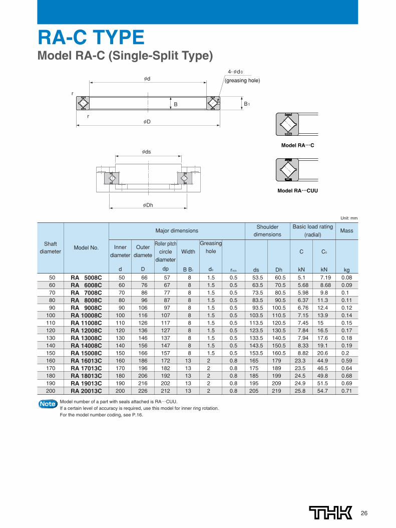
RA-C TYPEModel RA-C (Single-Split Type)
(greasing hole)φ d
φD
B B1
r
r
4-φ d0
φ ds
φDh
Model RA…CUU
Model RA…C
Shaftdiameter
Model No.
5060708090
100110120130140150160170180190200
50 66 57 8 1.5 0.5 53.5 60.5 5.1 7.19 0.0860 76 67 8 1.5 0.5 63.5 70.5 5.68 8.68 0.0970 86 77 8 1.5 0.5 73.5 80.5 5.98 9.8 0.180 96 87 8 1.5 0.5 83.5 90.5 6.37 11.3 0.1190 106 97 8 1.5 0.5 93.5 100.5 6.76 12.4 0.12
100 116 107 8 1.5 0.5 103.5 110.5 7.15 13.9 0.14110 126 117 8 1.5 0.5 113.5 120.5 7.45 15 0.15120 136 127 8 1.5 0.5 123.5 130.5 7.84 16.5 0.17130 146 137 8 1.5 0.5 133.5 140.5 7.94 17.6 0.18140 156 147 8 1.5 0.5 143.5 150.5 8.33 19.1 0.19150 166 157 8 1.5 0.5 153.5 160.5 8.82 20.6 0.2160 186 172 13 2 0.8 165 179 23.3 44.9 0.59170 196 182 13 2 0.8 175 189 23.5 46.5 0.64180 206 192 13 2 0.8 185 199 24.5 49.8 0.68190 216 202 13 2 0.8 195 209 24.9 51.5 0.69200 226 212 13 2 0.8 205 219 25.8 54.7 0.71
Unit: mm
RA 5008CRA 6008CRA 7008CRA 8008CRA 9008CRA 10008CRA 11008CRA 12008CRA 13008CRA 14008CRA 15008CRA 16013CRA 17013CRA 18013CRA 19013CRA 20013C
Major dimensionsShoulderdimensions
Basic load rating(radial)
Innerdiameter
d
Outerdiamete
D
Roller pitchcirclediameter
dp
Width
B B1
Greasinghole
d0
C
kN
C0
kNrmin ds Dh kg
Mass
Model number of a part with seals attached is RA…CUU.If a certain level of accuracy is required, use this model for inner ring rotation.For the model number coding, see P.16.
Note

HEAD OFFICE 3-11-6, NISHI-GOTANDA, SHINAGAWA-KU, TOKYO 141-8503 JAPAN INTERNATIONAL SALES DEPARTMENT PHONE:+81-3-5434-0351 FAX:+81-3-5434-0353
TAIWANTHK TAIWAN CO.,LTD.
TAIPEI HEAD OFFICEPhone:+886-2-2888-3818TAICHUNG OFFICEPhone:+886-4-2359-1505 TAINAN OFFICEPhone:+886-6-289-7668
KOREASEOUL REPRESENTATIVE OFFICE
Phone:+82-2-3468-4351SINGAPORETHK LM SYSTEM Pte. Ltd.
NORTH AMERICATHK America,Inc.
HEADQUARTERSPhone:+1-847-310-1111 Fax:+1-847-310-1271CHICAGO OFFICEPhone:+1-847-310-1111 Fax:+1-847-310-1182NORTH EAST OFFICE Phone:+1-845-369-4035 Fax:+1-845-369-4909ATLANTA OFFICEPhone:+1-770-840-7990 Fax:+1-770-840-7897LOS ANGELES OFFICEPhone:+1-949-955-3145 Fax:+1-949-955-3149SAN FRANCISCO OFFICEPhone:+1-925-455-8948 Fax:+1-925-455-8965DETROIT OFFICEPhone:+1-248-858-9330 Fax:+1-248-858-9455TORONTO OFFICEPhone:+1-905-820-7800 Fax:+1-905-820-7811
SOUTH AMERICATHK Brasil LTDA
Phone:+55-11-3767-0100 Fax:+55-11-3767-0101EUROPETHK GmbH
DÜSSELDORF OFFICEPhone:+49-2102-7425-0 Fax:+49-2102-7425-299
EUROPEAN HEADQUARTERSPhone:+49-2102-7425-555 Fax:+49-2102-7425-556
SHANGHAI OFFICEPhone:+86-21-6219-3000 Fax:+86-21-6219-9890BEIJING OFFICEPhone:+86-10-8441-7277 Fax:+86-10-6590-3557CHENGDU OFFICEPhone:+86-28-8526-8025 Fax:+86-28-8525-6357GUANGZHOU OFFICEPhone:+86-20-8523-8418 Fax:+86-20-3801-0456
CHINATHK (CHINA) CO.,LTD.
TURKEY OFFICEPhone:+90-216-362-4050 Fax:+90-216-569-7150
MOSCOW OFFICEPhone:+7-495-649-80-47 Fax:+7-495-649-80-44
FRANKFURT OFFICEPhone:+49-2102-7425-650 Fax:+49-2102-7425-699STUTTGART OFFICEPhone:+49-7150-9199-0 Fax:+49-7150-9199-888MÜNCHEN OFFICEPhone:+49-8937-0616-0 Fax:+49-8937-0616-26U.K. OFFICEPhone:+44-1908-30-3050 Fax:+44-1908-30-3070ITALY MILANO OFFICEPhone:+39-039-284-2079 Fax:+39-039-284-2527ITALY BOLOGNA OFFICEPhone:+39-051-641-2211 Fax:+39-051-641-2230SWEDEN OFFICEPhone:+46-8-445-7630 Fax:+46-8-445-7639 AUSTRIA OFFICEPhone:+43-7229-51400 Fax:+43-7229-51400-79SPAIN OFFICEPhone:+34-93-652-5740 Fax:+34-93-652-5746
EINDHOVEN OFFICETHK Europe B.V.
THK France S.A.S.Phone:+33-4-3749-1400
Phone:+31-040-290-9500 Fax:+31-040-290-9599
Fax:+33-4-3749-1401
HEADQUARTERSPhone:+86-411-8733-7111 Fax:+86-411-8733-7000
THK (SHANGHAI) CO.,LTD.Phone:+86-21-6275-5280 Fax:+86-21-6219-9890
Fax:+886-2-2888-3819
Fax:+886-4-2359-1506
Fax:+886-6-289-7669
Fax:+82-2-3468-4353
Fax:+65-6884-5550INDIABANGALORE REPRESENTATIVE OFFICE
Phone:+91-80-2330-1524
Phone:+65-6884-5500
Fax:+91-80-2314-8226
Global site : http://www.thk.com/
©THK CO., LTD. 200907030 E10 Printed in Japan
PRAGUE OFFICEPhone:+420-2-41025-100 Fax:+420-2-41025-199
Cross-Roller Ring Series
Precautions on use� Handling
� The separable inner or outer ring is fastened in place using special rivets, bolts or nuts when delivered. When installing it to thesystem, do not disassemble it. Also, erroneously installing the spacer retainer will significantly affect the rotational performance ofthe system. Do not disassemble the bearing.
� The matching mark of the inner or outer ring may be slightly misaligned when delivered. In that case, loosen the bolts that securethe inner or outer ring, and correct the alignment using a plastic hammer or the like, before installing it to the housing (let thesecuring rivets follow the housing).
� When installing or removing the Cross-Roller Ring, do not apply force to the securing rivets or the bolts.� When mounting the presser flange, take into account the dimensional tolerances of the parts so that the flange firmly holds the inner
and outer ring from the side.� Dropping or hitting the Cross-Roller Ring may damage it. Giving an impact to it could also cause damage to its function even if the
product looks intact.� Lubrication
� Since each Cross-Roller Ring unit contains high-quality lithium soap group grease No. 2, you can start using the product withoutreplenishing grease. However, the product requires regular lubrication since it has a smaller internal space than ordinary rollerbearings and because the rollers need frequent lubrication due to their rolling contact structure.
� To replenish grease, it is necessary to secure greasing holes that lead to the oil grooves formed on the inner and outer rings. As forthe lubrication interval, normally replenish grease of the same group so that it is distributed throughout the interior of the bearing atleast every six to twelve months.
� When the bearing is filled up with grease, the initial rotation torque temporarily increases. However, surplus grease will run off of theseals and the torque will return to the normal level in a short period. The thin type does not have an oil groove. Secure an oilgroove inside the housing for lubrication.
� Do not mix lubricants of different physical properties.� In locations exposed to constant vibrations or in special environments such as clean rooms, vacuum and low/high temperature,
normal lubricants may not be used. Contact THK for details.� When planning to use a special lubricant, contact THK before using it.
� Precautions on Use� Entrance of foreign matter may cause functional loss. Prevent foreign matter, such as dust or cutting chips, from entering the
system.� When desiring to use the system at temperature of 80℃ or higher, contact THK in advance.� If planning to use the Cross-Roller Ring in an environment where a coolant penetrates into the product, contact THK.� If foreign matter adheres to the product, replenish the lubricant after cleaning the product with clean white kerosene. � When using the product in locations exposed to constant vibrations or in special environments such as clean rooms, vacuum and
low/high temperature, contact THK in advance.
● “LM GUIDE” and “ ” are registered trademarks of THK CO., LTD.● The photo may differ slightly in appearance from the actual product.● The appearance and specifications of the product are subject to change without notice. Contact THK before placing an order.● Although great care has been taken in the production of this catalog, THK will not take any responsibility for damage resulting from typographical errors or omissions.● For the export of our products or technologies and for the sale for exports, THK in principle complies with the foreign exchange law and the Foreign Exchange
and Foreign Trade Control Law as well as other relevant laws.For export of THK products as single items, contact THK in advance. All rights reserved