CROSS CONNECTION CONTROL PROGRAM of UTAH · 1 CROSS CONNECTION CONTROL PROGRAM of UTAH April 2016...
51
1 CROSS CONNECTION CONTROL PROGRAM of UTAH April 2016 Cross Connection Control Commission Michael S. Moss, Secretary Division of Drinking Water 195 North 1950 West, 3 rd Floor P.O. Box 144830 Salt Lake City, Utah 84114-4830 Phone (801) 536-4200
Transcript of CROSS CONNECTION CONTROL PROGRAM of UTAH · 1 CROSS CONNECTION CONTROL PROGRAM of UTAH April 2016...
1
CROSS CONNECTION CONTROL
PROGRAM
of
UTAH
April 2016
Cross Connection Control Commission
Michael S. Moss, Secretary
Division of Drinking Water
195 North 1950 West, 3rd
Floor
P.O. Box 144830
Salt Lake City, Utah 84114-4830
Phone (801) 536-4200

2
CROSS CONNECTION CONTROL PROGRAM OF UTAH
GUIDELINES - REFERENCE
Page
I. SCOPE .....................................................................................................................................4
II. DEFINITIONS .........................................................................................................................5
III. AUTHORITY ......................................................................................................................... 6
A. Applicable Laws.................................................................................................................6
B. Regulations / Codes and Policies .......................................................................................6
C. Enforcement .......................................................................................................................7
IV. RESPONSIBILITIES ...............................................................................................................8
A. Division of Drinking Water ...............................................................................................9
1. Public Drinking Water System ....................................................................................9
2. Certified Backflow Technician ..................................................................................12
3. Hazard Assessment Official ......................................................................................13
B. Division of Occupational & Professional Licensing ........................................................13
1. Plumbing Inspection Official ....................................................................................13
2. Licensed Plumber .............................................................................................................14
C. Customer/Consumer .........................................................................................................14
V. STANDARDS ........................................................................................................................14
A. Cross Connection Control and Backflow Prevention Programs ......................................14
B. Certification of Backflow Technicians ............................................................................17
C. Degree of Hazard .............................................................................................................17
D. Types of Backflow ...........................................................................................................17
E. Methods of Protection ......................................................................................................18
F. Assembly Installation Criteria..........................................................................................18
G. Approved List for Backflow Prevention Assemblies/Devices.........................................23
H. Assembly Testing Frequency ...........................................................................................24
I. Assembly Repair ..............................................................................................................24
J. Assembly Test Result Reports .........................................................................................25
K. Assembly Location Reports .............................................................................................26

3
VI. POLICIES 25
A. Non-Industrial Connection Protection .............................................................................26
B. Residential and Small Sprinkling Systems ......................................................................27
C. Dual Source Sprinkling Systems ......................................................................................28
D. Installation of Not Approved Assemblies/Devices ..........................................................28
E. Line Sizing .......................................................................................................................29
F. Containment versus Isolation Techniques .......................................................................29
G. Privately Owned Drinking Water Wells ..........................................................................30
APPENDICES
A. Ordinance Guidance Document .......................................................................................31
B. List of Approved Backflow Prevention Assemblies/Devices ..........................................42
C. Approved Assembly Testing Methods .............................................................................44
D. List of Acceptable Testing Equipment .............................................................................46
E. Assembly Test Report Form ............................................................................................50

4
I. SCOPE
The scope of this document is to assist all public drinking water systems in the design,
implementation and enforcement of a viable, ongoing cross connection control program which
will ensure that both the water purveyor and the customer have exercised "reasonable diligence"
in protecting the public drinking water.
A cross connection is defined as, "Any actual or potential connection between a potable water
system and any other source or system through which it is possible to introduce into the public
drinking water system any used water, industrial fluid, gas or substance other then the intended
potable water." Cross connections and backflow incidences in the state of Utah have resulted in
dangerous, highly contaminated water unexpectedly entering public drinking water systems.
Irrigation waters, oil, toxic boiler compounds, sewage, pesticides, and other extremely dangerous
contaminants have found their way into Utah public drinking water systems due to cross
connections.
Millions of taxpayer dollars are spent every year to protect drinking water sources, systems, and
treatment facilities, but even with the best infrastructure the integrity of the drinking water
system and the quality of the water can be compromised by a single cross connection. One
single cross connection can result in illness and, in an extreme case, death which could result in
millions of dollars in court settlements as well as destroy the public's confidence of the public
drinking water system.
Legal actions concerning pollution or contamination of public drinking water systems brought
against water purveyors by consumers who have been affected by backflow incidences have
reached astronomical financial proportions with the water purveyors often being found negligent
in their methodology of protection or in the quality of the water they supply.
These legal proceedings, as well as federal law, state law, plumbing codes, rules and regulations,
all mandate the specific needs for an on-going cross connection control program by all public
drinking water systems serving the public whether publicly or privately owned.
There is a joint responsibility contract (whether verbal or written) that exist between the public
drinking water system and the customer. This contract dictates that the water purveyor will
provide a safe, adequate supply to the customer who in turn will maintain their privately owned
plumbing system in compliance with local ordinances, requirements, codes and policies.
If this joint responsibility contract is enforced, it will protect both the public drinking water
system and the private customer's responsibility and liability.
This type of program would enable the water purveyor to protect the quality of water in the
distribution system thus exercising "reasonable diligence" for the protection of the safe drinking
water supply.

5
II. DEFINITIONS
A. Administrative Authority shall mean the individual, official, board, department, or
agency established and authorized by a state, county, city, or other political subdivision
created by law to administer and enforce the provisions of the cross connection control
program and/or the plumbing code.
B. Backflow shall mean the undesirable reversal of flow of water or mixtures of water and
other liquids, gases, or other substances into the distribution pipes of the potable water
supply from any source.
C. Backpressure shall mean the phenomenon that occurs when the customer's pressure is
higher than the supply pressure. This could be caused by an unprotected cross connection
between a drinking water supply and a pressurized irrigation connection, a boiler, a
pressurized industrial process, elevation differences, air or steam pressure, use of booster
pumps or any other source of pressure.
D. Backsiphonage shall mean a form of backflow due to a reduction in system pressure
which causes a sub-atmospheric pressure to exist at a site in the water system.
E. Certified Backflow Technician shall mean an individual that has successfully
completed a Division of Drinking Water approved backflow certification course with a
written and practical examination, and has maintained this certification in accordance with
R309-305, Certification Rules for Backflow Technicians.
F. Consumer/Customer shall mean the owner or operator of a privately or publicly
owned plumbing system(s) having a service connection from the public drinking water
system.
G. Containment (Meter or Point of Connection Protection) shall mean the practice of
installing approved backflow prevention assemblies/devices at the service connection of
consumers in order to protect the public drinking water system from any backflow from the
consumers plumbing system.
H. Contaminate shall mean any substance introduced into the public drinking water
system which creates a threat to the public health such as poisoning, pathogenic organisms
or any other public health concern.
I. Cross Connection shall mean any actual or potential connection between a potable
water system and any other source or system through which it is possible to introduce into
the public drinking water system any used water, industrial fluid, gas or substance other
then the intended potable water.
J. Degree of Hazard shall mean either a pollutant (non-health) or contaminate
(health) hazard that may be introduced into the public drinking water system through a
cross connection. Through an evaluation of the consumers plumbing system, the threat to

6
public health (the degree of hazard) will be determined. In the past these terms have been
referred to as high hazard for health and low hazard for non-health.
K. Isolation (Plumbing Code Compliance) shall mean the practice of installing approved
backflow prevention assemblies/devices at each point of cross connection or system outlet
as required by Plumbing Code as adopted by the State and its amendments.
L. Pollutant shall mean any substance introduced into the public drinking water system
which does not create a threat to the public health but which does adversely and
unreasonably affect the aesthetic quality of the water.
M. Public Drinking Water System shall mean a water system that is either publicly or
privately owned, that provides water for human consumption and other domestic uses,
which: has at least 15 service connections, and/or serves an average of at least 25
individuals at least 60 days out of the year.
N. Service Connection shall mean the terminal end of the public drinking water system
where the water purveyor transfers jurisdiction and sanitary control of the water. If a water
meter is present then the service connection exists at the downstream end of the meter.
O. Water Purveyor shall mean the public or private owner or responsible party of a
public drinking water system.
III. AUTHORITY
A. Applicable Laws:
Federal Public Law 104-182, (the Safe Drinking Water Act and Amendments of 1996),
identifies the responsibility of each public drinking water system to protect the quality of
the water supplied to the consumers from any sources of contamination. As stated in the
US EPA Cross Connection Control Manual, the water purveyor must provide a water that
complies with all EPA standards at the source and deliver it to the customer without the
quality being compromised as a result of it's delivery through the distribution system.
Utah Code, Section 19-4-112 (2d) states, "there shall be no cross connection between the
potable (drinking water system) and nonpotable (auxiliary water supply) systems.
B. Regulations/Codes:
Utah Public Drinking Water Rules (UPDWR), Section R309-105-12 place the following
requirements on public drinking water suppliers:
"The water supplier shall not allow a connection to his system which may jeopardize its
quality and integrity”. In addition this rule identifies the need for a viable cross connection
control program which includes an inventory of testable assemblies, testing and service
records for the assemblies, testing frequency requirements and adherence to all

7
requirements of Plumbing Code as adopted by the State and its amendments.
Occupation Safety and Health (OSHA) Rules and Regulations Part 1910-Subpart J, Section
1910.41, require that each employer furnish his or her employee(s) with an adequate safe
drinking water supply. This infers the need to protect against any backflow which would
create an unsafe drinking water supply within the consumer’s distribution system as well as
the public drinking water system.
The adopted Plumbing Code requires that an approved backflow prevention/devices be
properly installed, tested and utilized.
The Division of Drinking Water shall maintain a list of backflow prevention devices and
assemblies approved for containment use and applicable for use within the jurisdiction of
the public water system. This list shall be accessible on the Drinking Water webpage.
C. Enforcement:
There are two tiers of enforcement responsibilities within a Cross Connection Control
Program. The first tier is with the Utah Department of Environmental Quality, Division of
Drinking Water where the Public Drinking Water Rules apply to the public drinking water
systems.
The second tier involves the public drinking water system's enforcement of a local
ordinance, policy, or requirements applied to the customer.
TIER 1 Division of Drinking Water:
The enforcement methodologies associated with the Division of Drinking Water's
application of the Public Drinking Water Rules vary from system to system, depending on
the size and complexity of the situation. The usual enforcement means are:
1. A written Notice of Violation; issued by the Division of Drinking Water.
2. An Administrative Order; issued through the Utah Drinking Water Board wherein
the public drinking water system is ORDERED to do certain things to come into
compliance with the Public Drinking Water Rules.
3. A Rating Change of the Drinking Water System. There are currently three ratings
applied to public drinking water systems:
a. APPROVED: This rating means that the water supplier is substantial in
compliance with all drinking water rules.
b. CORRECTIVE ACTION: This rating reflects that some areas of deficiencies
have been noted but the system is taking definite steps towards correcting these
deficiencies.

8
c. NOT APPROVED: This rating identifies that the system is not in compliance
with the drinking water rules and has been given ample opportunity to address
certain noted deficiencies, and the system has failed to do so. This rating, when
assigned, stops all federally insured home loans and many funding programs
involving state and federal grants/loans. This sanction will remain in place until
such time as the system adequately addresses the problems which caused this
rating to be assigned.
TIER 2 Public Drinking Water Systems:
The second tier of enforcement involves methodologies which the public drinking water
system applies to the customer. This is mandated and authorized by the adoption of some
form of local authority (hereinafter referred to as ordinance) (see Appendix A - Ordinance
Guidance Document). Within the ordinance, there should be provisions that: a) require
protection on all cross connections; b) require periodic testing of all backflow prevention
assemblies; c) require periodic hazard assessments; d) identify enforcement methods which
should include discontinuation of water service to customer's that violate the ordinance; and
e) identify who will administer the program. There could also be methodologies within the
ordinance for service renewal fees, connection fees, inspection fees and/or a surcharge for
maintenance of hazardous connections.
This type of enforcement (public drinking water systems enforcing their ordinances upon
the customer) is legally viable, as long as there is a local ordinance in place that meets the
basic criteria of the cross connection control program of the state.
IV. RESPONSIBILITIES
In the State of Utah, the authority and responsibility for the enforcement of an effective
Cross Connection Control and Backflow Prevention Program lies both within the
Department of Environmental Quality, Division of Drinking Water (DDW) and the
Department of Commerce, Division of Occupational and Professional Licensing (DOPL).
The DOPL has the responsibility to ensure that all new plumbing is installed according to
the Plumbing Code and associated amendments adopted by the State of Utah. This
responsibility includes that no installation of potable water supply piping or part thereof
shall be made in such a manner that it will be possible for used, unclean, polluted, or
contaminated water, mixtures, or substances to enter any portion of such piping and pose a
threat to the integrity of the water contained within the potable water supply. Where such
connections are required they shall be protected with the appropriate method of protection,
installed in the proper application and in accordance with the appropriate installation
criteria.
The DDW and each public drinking water system have the responsibility of protecting the
quality and integrity of the drinking water contained within the public drinking water
systems' distribution system. Due to the fact that private plumbing systems are in a

9
constant state of change; which may or may not be installed by a licensed plumber or be
inspected to ensure that the changes meet the adopted Plumbing Code requirements, the
quality of the drinking water is the ultimate responsibility of each public drinking water
system. In order to carry through with this responsibility, each public drinking water
system is required to evaluate the backflow prevention issues specific to its distribution
system and to implement a Cross Connection Control Program to prevent any type of
backflow of this "used" water into the distribution system.
Because of this shared responsibility between the DDW and DOPL, an effective Cross
Connection Control Program is one that involves both the water purveyor and the plumbing
inspection or code official, as well as many other individuals involved in the backflow
industry. The key individuals and their respective responsibilities are outlined in the
following sections.
A. Utah Department of Environmental Quality, Division of Drinking Water, Drinking
Water Board and Cross Connection Control Commission:
These government agencies are charged with the responsibility of promulgating and
enforcing laws and rules to carry out an effective cross connection control program for the
State of Utah.
The Utah Department of Environmental Quality, Division of Drinking Water has the
primary responsibility of ensuring that water purveyors operate public drinking water
systems in such a manner as to preserve and protect public health, including protecting the
system from backflow.
The Drinking Water Board has the primary responsibility of promulgating and enforcing
the Public Drinking Water Rules that regulate public drinking water systems and the
certification of backflow technicians.
The Cross Connection Control Commission has the responsibility of advising the Drinking
Water Board as to the appropriateness of rules, regulations, codes, enforcement activities,
etc., as they relate to cross connection control programs, policies and backflow prevention
technician certification.
The Division of Drinking Water, as staff to the Cross Connection Control Commission and
the Drinking Water Board, will work toward ensuring that each public drinking water
system protects its distribution system from possible contamination.
Based on an evaluation of each individual water system by the system personnel, the
protection may be accomplished by various methods (see Policy F, Containment versus
Isolation).
1. Public Drinking Water System:
Under the Utah Public Drinking Water Rules (Section R309-105-12) the water

10
purveyor has the primary responsibility for the prevention of any substance including
water from any unapproved source, from entering the public drinking water system.
The water purveyor has a responsibility to eliminate any situation where a water
connection may jeopardize the quality of the drinking water within the public drinking
water system. This may require discontinuance of water service for a customer who
refuses to comply.
The public drinking water system is prohibited by these rules from installing or
maintaining a water service connection to a consumer where a pollutant, plumbing or
contamination hazard exist, unless the public drinking water system is protected against
backflow by an approved backflow prevention assembly/device properly installed and
maintained, as required by the adopted Plumbing Code.
The public drinking water systems' responsibilities include the source of supply, all of
the public distribution system, the service lines and ends at the consumer's meter or
property line. In addition, each public drinking water system must work towards
ensuring that the customer properly protects the quality and integrity of the drinking
water contained within the private plumbing system as well as the public water
distribution system.
Activities that a customer engages in could easily jeopardize the quality of the drinking
water if a backflow incident occurs. For this reason, the water purveyor must require,
as a condition of connection for service, that the customer institute protection measures
that may include: installation, maintenance, and periodic testing of approved backflow
prevention assemblies or inspection of devices. In addition, the water purveyor shall
exercise "reasonable diligence" to ensure that not only the public drinking water
system, but also the customer has taken the proper steps to protect the public drinking
water system from possible contamination from whatever activities the customer
engages in.
To ensure that the proper precautions are taken, the public drinking water system is
required to determine the "degree of hazard" to the public drinking water system when
the service connection is made. In the case of an existing connection, a hazard
assessment investigation or survey must be conducted to determine the "degree of
hazard" within the existing site. Also, education is needed for the customer to
understand the dangers of cross connections and their personal liability should a
backflow event occur.
A hazard assessment is a detailed inspection of the customer facilities within the
customer's plumbing system. This inspection would involve inspecting all water uses
and piping within the system. If the customer refuses access to their facilities, the
plumbing system must be classified as a high hazard connection and appropriate
protection must be required at the service connection.
When it is determined that a backflow prevention assembly is required for the
protection of the public drinking water system; the water purveyor shall require as a

11
condition of water service:
a. Installation of a backflow assembly/device at each service connection
(containment, meter protection) and/or recommend the appropriate protection is
installed at each point of cross connection (isolation, plumbing code compliance)
within the consumer’s water system.
Upon a requirement to install an assembly/device, the supplier must consider the
degree of hazard AND the hydraulics of the customer's water system (thermal
expansion, etc.) to ensure that the assembly/device is installed in accordance with
its proper installation criteria and in the appropriate application.
b. Annual compliance inspection of the customer's water system, which may
include the minimum annual testing of approved backflow prevention
assemblies/devices.
c. Maintenance of records of each test and subsequent maintenance and repair,
including materials or replacement parts used for approved backflow prevention
assemblies/devices within their jurisdiction as well as records of hazard assessment
investigation or surveys.
Copies of all backflow assembly test reports (reference Appendix E, Assembly
Test Report) which are completed during the compliance inspection within the
public drinking water system, will be maintained by the water purveyor and be
available for inspection by the Division of Drinking Water staff or their designees
(R309-101-4.3 and R309-105-12) during sanitary surveys. The customer and the
Certified Backflow Technician should also retain copies of the test results for their
files for five years.
Each public drinking water system must adopt some form of local authority or
ordinance (See Appendix A, Ordinance Guidance Document). Within the
ordinance, there should be provisions that: a) require protection on all cross
connections; b) require periodic testing of all backflow prevention assemblies; c)
require periodic hazard assessments; d) identify enforcement methods which
should include discontinuation of water service to customer's that violate the
ordinance; and e) identify who will administer the program. The ordinance should
also address the methodology of protection (See Policy F, Containment versus
Isolation Requirement) and technology.
The public drinking water system shall also design and implement a general public
awareness and education program so that their customers will be apprised of the
dangers of cross connections. The customers must be informed of the hazards
associated with common activities that they, themselves, may impose on the public
drinking water system.
The public drinking water system should look towards protection of all public

12
facilities (golf courses, cemeteries, libraries, parks, public buildings, etc.) prior to
full implementation of a cross connection control program on the customers of the
public drinking water system.
WHEN A BACKFLOW OR SUSPECTED BACKFLOW INCIDENT OCCURS,
THE DIVISION OF DRINKING WATER SHALL BE NOTIFIED
IMMEDIATELY AT 536-4200 (OR 536-4123 AFTER HOURS), AND WATER
SAMPLES SUFFICIENT TO DETERMINE THE DEGREE AND EXTENT OF
CONTAMINATION MUST BE DRAWN FOR ANALYSIS.
2. Certified Backflow Technician:
When employed by a public drinking water system or by a customer to test, repair
and/or maintain any backflow prevention assembly, the Certified Backflow Technician
will have the following responsibilities:
a. Ensure that acceptable procedures are used for testing, repairing and
maintaining any backflow prevention assembly (See Appendix C, Approved
Assembly Testing Methods).
b. Make reports of such testing and/or repair to the customer and the public
drinking water system, on forms approved for use by the Cross Connection Control
Commission (Reference Appendix E, Test Report Form).
c. Include on report a list of any materials or replacement parts used to effect a
repair or perform maintenance of that assembly.
d. Ensure that any replacement parts are equal in quality to parts originally
supplied within the assembly and that they are supplied only by the manufacturer
or their agent.
e. Avoid changing the design, material, or operational characteristics of the
assembly during any repair or maintenance.
f. Perform test and be responsible for the competency and accuracy of all testing
and reports thereof.
g. Ensure the status of technician's certification is current.
h. Be equipped with and competent in the use of all tools, gauges, and equipment
necessary to properly test, repair, and/or maintain a backflow prevention assembly.
Failure to report a failing assembly to the public drinking water supplier which
supplies water to the premises protected by that particular assembly within five (5)
working days may be grounds for revocation of a backflow technicians'
certification.

13
Any commercially available Class II or III Certified Backflow Technician is
authorized to test any backflow prevention assembly at the invitation of the owner,
and to report the results of that test to the owner and the water purveyor. However
any repairs on backflow prevention assemblies which did not pass a test conducted
by a Certified Backflow Technician, must be performed by a tester having
appropriate licensure from the Department of Commerce, Division of Professional
Licensing who also holds a current Class II or III Backflow Technician Certificate
or by an "agent of the owner" of the assembly.
3. Hazard Assessment Official:
This official can be anyone whom the local jurisdiction has authorized and delegated to
perform compliance and/or hazard assessment inspections or surveys and who should
also hold a Class I or Class III Utah Backflow Technician Certificate.
This individual shall conduct hazard assessments to determine the "degree of hazard"
to the public drinking water system from an individual service connection (new or
existing). In the case of an existing connection, a hazard assessment investigation or
survey must be conducted to determine the "degree of hazard" within the existing site,
as well as educating the customer to the dangers of cross connections and their personal
liability should a backflow event occur. A hazard assessment is a detailed inspection of
the customer facilities within the service connection. This inspection would involve
inspecting all water uses and piping within the connection. If the customer refuses
access to their facilities, the service connection must be classified as a high hazard
connection and appropriate protection must be required at the service connection.
B. Utah Department of Commerce, Division of Occupational and Professional Licensing,
Uniform Building Code Commission, Plumbing/Health Advisory Committee,
Plumbers Licensing Board, Building Inspector Licensing Board:
These government agencies are charged with the responsibility of promulgating and
enforcing laws, rules, regulations, policies and carrying out an effective and standardized
statewide plumbing code, and the licensing of plumbers and plumbing inspectors.
The Utah Department of Commerce, Division of Occupational and Professional Licensing
has the responsibility of ensuring that the plumbers and plumbing inspectors licensed under
their authority have met all the training and educational requirements promulgated by the
Plumbers Licensing Board and the Building Inspector Licensing Board.
The Plumbing/Health Advisory Committee has the responsibility of advising the Uniform
Building Code Commission as to the appropriateness of rules, regulations, codes,
enforcement activities, etc., as they relate to the plumbing code adopted by the State.
1. Plumbing Inspector/Code Official:
Plumbing inspection plays a key role in any political jurisdiction. Plumbing inspection
14
departments and code officials have the responsibility to not only review building plans
and inspect plumbing as it is installed. The inspector also has the explicit responsibility
of preventing any unprotected cross connections from being installed into any
structures within their jurisdiction.
Where the review of any building plans suggest or detects potential for a cross
connection being made an integral part of the potable water system, the inspector or
code official must REQUIRE such cross connection be either eliminated or be provided
with an approved backflow prevention assembly/device in accordance with the adopted
Plumbing Code and associated amendments.
In requiring a device or assembly, the inspector or code official must determine the
degree of hazard presented to the potable water system AND the hydraulics of the
customer's water system (thermal expansion protection, etc.), to ensure the proper
assembly/device is installed in accordance to its proper installation criteria.
The local code official's responsibility begins at the point of service, (the downstream
side of the meter or property line) and carries throughout the entire length of the
customer’s drinking water system.
The plumbing inspector will inquire about the intended use of the potable water at any
point where it is suspected that a cross connection may be made or where one is
actually designed by the plans. When such a cross connection (actual or potential) is
discovered, the code official shall require that an approved backflow prevention
assembly/device be installed in accordance with the adopted Plumbing Code.
2. Licensed Plumber:
The licensed plumber has the responsibility to ensure that all his work is installed in
accordance with the adopted plumbing code and associated amendments.
C. Customer:
The public water system customer has the primary responsibility of maintaining his private
plumbing system in compliance with the current plumbing code.
The customer may be required to bear the responsibility and expense of installing,
maintaining and inspecting all high hazard air gaps, atmospheric vacuum breakers, hose bib
vacuum breakers, and the testing, repairing and maintenance of all approved pressure
vacuum breakers, double check valves assemblies, dual check valve devices, and reduced
pressure zone backflow prevention assemblies within his premises.
V. STANDARDS
A. Cross Connection Control and Backflow Prevention Programs:

15
Every public drinking water system in the State of Utah is required to have a cross
connection control program in place as stated in the Public Drinking Water Rules section
R309-105-12. A cross connection control program consists of a number of components
which when properly administrated are designed to prevent contamination from entering
the public drinking water distribution system.
The main components of an effective cross connection control program are: local authority;
public awareness; trained staff; record keeping; and on-going enforcement. These
components are the standard against which the public drinking water system's cross
connection control and backflow prevention program will be measured.
1. Local Authority:
This would consist of an ordinance, bylaw, or some other type of legal provision
established by the council, board, or governing legal body, that would authorize the
public drinking water system to carry out a cross connection control program. Specific
items to be covered in this ordinance would include:
a. Requirements for protection of all cross connections;
b. Requirements for periodic testing of assemblies and/or devices;
c. Requirements for periodic hazard assessment investigations or surveys;
d. Identify enforcement methods including authority to discontinue service to
connections that refuse to comply; and
e. Identify responsible party for administering program and enforcement.
2. Public Awareness and Education:
A good public awareness program will annually provide information to the public
concerning:
a. What cross connections are;
b. How they can be prevented;
c. What types of protection are available; and
d. The concerns associated with thermal expansion where protection is required.
In addition, a good public awareness program will target more than the public drinking
water system customers. Other groups or individuals are necessary to ensure that the
cross connection control program will be successful in the community. For example,
presentations can be made to plumbing supply stores, school districts, and civic groups.

16
3. Trained or Certified Staff:
It is recommended but not required that at least one member of the public drinking
water system's staff be trained and certified as a backflow technician. It is, however,
imperative though that a least one member of the system's staff have adequate training
in the basics of cross connection control and how to manage a program.
This training is made available to managers and operators throughout the State through
organizations such as the Rural Water Association of Utah, Intermountain Section of
the American Water Works Association, Rural Community Assistance Corporation and
the Utah Chapter of the American Backflow Prevention Association. Division of
Drinking Water staff is also available to provide training in the area of cross connection
control.
4. Record Keeping:
Once a public drinking water system has an ordinance and has established a cross
connection control program, an annual detailed record keeping process must be
established and maintained. Records should be made and kept concerning the
following:
a. All surveys or inspections;
b. Inventory and locations of assemblies and high hazard air gaps;
c. Test histories and inspection records of the inventoried sites;
d. Any backflow incidents;
e. All corrective actions taken; and
f. All compliance and enforcement actions.
5. On-going Enforcement Program:
The program will only be as effective as the individuals who are authorized to carry it
out. Ideally this would extend to the building inspection and or plumbing inspection
departments where possible; but as a minimum someone in the water system shall be
authorized to administer the program and take the necessary compliance actions.
Annual testing of backflow prevention assemblies may be done by public drinking
water system personnel or by commercially available certified backflow technicians as
required by the water purveyor. Annual hazard assessment investigations or surveys
should be done by public drinking water system personnel; however, they may be
preformed by commercially available certified backflow technicians as allowed by the

17
water purveyor.
It is the combination of all program components on an annual basis that protect the
safety and health of the water consumers as well as lower the water system's legal
liability. If only one or two of the components are addressed then the system may
actually be increasing its vulnerability.
B. Certification of Backflow Technicians:
The authority to certify backflow technicians (all three Classes) is found in the Utah Code,
Section 19-4-104 (4a). Rules concerning the certification of the three Classes of backflow
technicians have been written and adopted by the Cross Connection Control Commission
and adopted by the Utah Drinking Water Board (R309 305).
Each Certified Backflow Technician will be issued a five digit certification number through
the Division of Drinking Water. All test reports will have this five digit number in the
appropriate areas of the test form.
The Division of Drinking Water will maintain a list of all certified technicians and those
certified Class II and III technicians who are available for commercial testing.
C. Degree of Hazard:
For cross connection control and backflow prevention, there will are only two (2) “degrees
of hazard". These degrees of hazard may also be found in the Plumbing Code, as adopted
by the State of Utah.
The definitions of the two "degrees of hazard" are:
1. Low or non-health hazard: Pollutants, aesthetic (color, odor, taste, appearance)
no health effects if consumed.
2. High or health hazard: Contaminants, any toxic substances or pathogens that
may cause illness or death if consumed.
In determining the Degree of Hazard, the health impact to young children, the elderly
and the immunocompromised, or any other health-compromised population must be
taken into account. If the water purveyor is in need of assistance in determining the degree
of hazard that a particular service connection or cross connection is presenting to the public
drinking water system the Division of Drinking Water should be contacted for assistance.
D. Types of Backflow:
Independent of the "Degree of Hazard" determination, there are two causes or "types" of
backflow. They are:

18
1. Backsiphonage: This phenomenon occurs when the supply pressure is reduced to
0 psi or below, which may cause a vacuum within the water supply system. This could
be a result of high usage demand, fire flows, line breaks, or turning off the main supply
for maintenance and repair.
2. Backpressure: This phenomenon occurs when the customer's pressure is higher
than the supply pressure. This could be caused by a cross connection between a
drinking water supply and a pressurized irrigation connection, a boiler, a pressurized
industrial process, elevation differences, air or steam pressure, use of boosters pumps
or any other source of pressure.
E. Methods of Protection:
The appropriate method of backflow protection to be utilized will be based on the degree of
hazard, the type of backflow conditions present, as well as the specific installation criteria
for each method of backflow protection (See Section V, F-Assembly Installation Criteria).
Degree of Hazard Type of Backflow Approved Method of Protection
High or Low Backsiphonage &
Backpressure
Air Gap
High or Low Backsiphonage &
Backpressure
Reduced Pressure Zone Backflow
Prevention Assembly (RP)
High or Low Backsiphonage ONLY Pressure Vacuum Breaker (PVB)
High or Low Backsiphonage ONLY Spill-Resistant Vacuum Breaker (SVB)
High or Low Backsiphonage ONLY Atmospheric Vacuum Breaker (AVB)
Low Backsiphonage &
Backpressure
Double Check Valve Assembly (DC)
Low Backsiphonage ONLY Hose Bibb Vacuum Breaker (HBVB)
**Low Backsiphonage ONLY Dual Check Device
**For Non-Industrial meter box installation only. Installation of these devices as well as any
other backflow prevention assembly/device will create a closed water system which may result
in thermal expansion in the customer’s internal water system. Written notification of installation
is required (see Policy A, Non-Industrial Connection Protection).
Backflow prevention assemblies/devices shall be provided at any installation as required by the
public drinking water system, the Division of Drinking Water, and as required by the adopted
Plumbing Code.
F. Assembly Installation Criteria:

19
Backflow prevention assembly/device installation criteria can also be found in the adopted
Plumbing Code.
Backflow prevention assemblies/devices shall be installed to provide at least the degree of
protection as dictated by the adopted Plumbing Code.
Prior to the installation of any backflow prevention assembly or device, the owner of the
system must be notified that the installation of a backflow prevention assembly/device may
create a closed system which could result in a thermal expansion hazard. Under such
circumstances, the water system must inform the customer adequately and to the point that
the customer understands and assumes responsibility for that phenomenon.
In order to ensure smooth flow characteristics entering and exiting any backflow prevention
assembly or device, the approved assembly and/or device will be of an equal line size as to
the incoming and outgoing water service line (See Section VI, Policy E-Line Sizing).
Prior to installation, all backflow prevention assemblies/devices, installed under the
jurisdiction of the public drinking water system, must appear on the approved list as
maintained by the Utah Department of Environmental Quality, Division of Drinking Water,
(See Appendix B, List of Approved Backflow Prevention Assemblies/Devices). If any
backflow prevention assembly/device which has not been approved is found in use as a
primary backflow preventer within the direct jurisdiction of the public drinking water
system, that assembly/device must be removed and replaced with a state approved
assembly/device.
If an existing backflow prevention assembly is found in operation that at the time of initial
installation was on the "approved" list, but is no longer listed, that assembly may remain in
operation as long as it passes the required testing. When the assembly can no longer pass
the required test, it must be removed from service and be replaced by an approved
assembly of an equal or greater degree of protection.
Backflow prevention assemblies and devices must be installed within the following
installation criteria:
1. Air Gap: Air gap means a physical separation between the discharge end of a
drinking water supply pipe and a receiving vessel.
a. The air gap shall be one inch, or twice (2x) the diameter of the incoming pipe
(measured within 10 pipe diameters of the termination of the line), WHICHEVER
IS GREATER. This measurement will be taken from the end of the water line to
the flood rim of the receptacle or vat (the overflow or drain line will not be
construed as the flood rim level).
b. Where the air gap is within two (2) pipe diameters (horizontal measurement)
of a wall or vertical surface, the air gap shall be increased to a minimum of 1.5

20
inches or to three (3x) times the incoming pipe diameter, WHICHEVER IS
GREATER.
c. In any high hazard installation the air gap will be inspected after initial
installation and at least annually thereafter by a Certified Backflow Technician.
2. Reduced Pressure Principle (RP) Backflow Prevention Assembly:
An RP assembly consists of two (2) independently acting internally loaded check
valves, together with a hydraulically operated mechanically independent pressure
differential relief valve located between the check valves and below the first check
valve, four (4) properly located test cocks and two (2) tightly closing shut off
valves.
An RP assembly may be used to protect against a high (health) hazard or low (non
health) hazard and against backsiphonage and/or backpressure type backflows.
a. The assembly shall be protected from freezing and vandalism where
applicable.
b. The bottom of the RP assembly shall be a minimum of 12 inches above the
ground or floor. The assembly owner, when necessary, shall provide devices or
structures to facilitate testing, repair, and/or maintenance and to insure the safety of
the backflow technician.
c. The body of the RP assembly shall not be closer than 12 inches to any wall,
ceiling, or obstacle, and shall be readily accessible for testing, repair and/or
maintenance
d. RP assemblies shall NOT be installed in a pit.
e. The relief valve on the RP assembly shall not be directly connected to any
waste disposal line, including sanitary sewer, storm drains, or vents.
f. RP assemblies shall be maintained as an intact assembly.
g. The assembly shall be installed in a horizontal position only unless it appears
on the Division of Drinking Water Approved Assembly List approved for
installation in a vertical orientation.
3. Double Check Valve (DC) Assembly:
A DC assembly consists of two (2) independently operating internally loaded check
valves, two (2) tightly closing shutoff valves, and four (4) appropriately located test
cocks.

21
A DC assembly may be used to protect against low (non health) hazards only and
backsiphonage and/or backpressure backflow conditions.
a. The bottom of the DC assembly shall be a minimum of 12 inches above the
ground or floor. The assembly owner, when necessary, shall provide devices or
structures to facilitate testing, repair and/or maintenance and to insure the safety of
the backflow technician.
b. The body of the DC assembly shall be a minimum of 12 inches from any
walls, ceilings, or obstacle and shall be readily accessible for testing, repair and
maintenance.
c. If installed in a pit, the DC assembly shall be installed with a minimum of 12
inches of clearance between all sides of the vault including the floor and roof or
ceiling with adequate room for testing and maintenance.
d. The DC assembly shall be maintained as an intact assembly.
e. The DC assembly shall be installed in a horizontal position only unless it
appears on the Division of Drinking Water Approved Assembly List for
installation in the vertical position.
f. The assembly shall be protected from freezing and vandalism where
applicable.
4. Pressure Vacuum Breaker (PVB) Backsiphonage Prevention Assembly:
A PVB assembly consists of a internally loaded check valve, an internally loaded air
inlet valve (poppet) located on the discharge side of the check valve, two (2) tightly
closing shut off valves, and two (2) appropriately located test cocks.
A PVB assembly may be used to protect against high (health) hazard or low (non
health) hazards, backsiphonage backflow conditions only.
The PVB assembly may be subjected to continuous pressure.
a. The PVB assembly shall not be installed in an area that could be subjected to
backpressure or back drainage conditions.
b. The PVB assembly shall be installed a minimum of 12 inches above all
downstream piping and the highest point of use.
c. The PVB assembly shall be readily accessible for testing, repair and/or
maintenance.
d. The PVB assembly shall not be installed below ground or in a vault or pit.

22
e. The PVB assembly shall be maintained as an intact assembly.
f. The PVB assembly shall be installed in a vertical position only.
g. The assembly shall be protected from freezing and vandalism where
applicable.
5. Spill-Resistant Pressure Vacuum Breaker (SVB) Backsiphonage Prevention
Assembly:
A SVB assembly consists of an internally loaded check valve, an internally loaded air
inlet valve (poppet) located on the discharge side of the check valve, two (2) tightly
closing shut off valves, and one (1) appropriately located test cock and one (1)
appropriately located bleed/vent valve.
A SVB assembly may be used to protect against high (health) hazard or low (non
health) hazards, backsiphonage backflow conditions only.
The SVB assembly may be subjected to continuous pressure.
a. The SVB assembly shall not be installed in an area that could be subjected to
backpressure or back drainage conditions.
b. The SVB assembly shall be installed a minimum of 12 inches above all
downstream piping and the highest point of use.
c. The SVB assembly shall be readily accessible for testing, repair and/or
maintenance.
d. The SVB assembly shall not be installed below ground or in a vault or pit.
e. The SVB assembly shall be maintained as an intact assembly.
f. The SVB assembly shall be installed in a vertical position only.
g. The assembly shall be protected from freezing and vandalism where
applicable.
6. Atmospheric Vacuum Breaker (AVB):
An AVB device consists of an air inlet valve (poppet), a check seat and an air inlet
port. There are no shut-off valves or test cocks on this type of device.
An AVB may be used to protect against high (health) or low (non health) hazards,
backsiphonage backflow conditions only.
23
a. The AVB shall not be installed in an area that could be subjected to
backpressure or back drainage conditions.
b. The AVB shall not be installed where it may be subjected to continuous
pressure for more than 12 consecutive hours at any time.
c. The AVB shall be installed a minimum of six (6) inches above all downstream
piping and the highest point of use.
d. The AVB shall be installed on the discharge (downstream) side of any valves.
e. The AVB shall be installed in a vertical position only.
f. The assembly shall be protected from freezing and vandalism where
applicable.
7. Hose Bib Vacuum Breaker:
A Hose Bib Vacuum Breaker device consists of a single internally loaded check valve,
atmospheric vents around the device, and an anti-removal device (breakaway set screw,
spring threads, etc.).
A Hose Bib Vacuum Breaker may be used to protect against low (non health) hazards
only, backsiphonage backflow conditions only, for hose bibs only.
a. The Hose Bib Vacuum Breaker shall be installed with the anti-removal
locking device engaged.
8. Dual Check Valve Device:
An approved Dual Check Valve device consists of two (2) independently operating,
spring loaded check valves.
A Dual Check Valve device may be installed, as a secondary protection method of the
drinking water system, within the meter yolk of non-industrial, low hazard connections.
All other points of cross connection would then require the isolation method of
protection (i.e., lawn sprinkling system, home boiler, etc.).
G. Approved List for Backflow Prevention Assemblies\Devices:
To gain Division of Drinking Water approval for use within a public drinking water system,
all backflow prevention assemblies must be in-line serviceable (repairable), in-line testable
and have certification through third party certifying agencies. Third party certification will
consist of any combination of two (2) laboratory or field test certifications. Acceptable
third party laboratory certifying agencies are; ASSE (American Society of Sanitary

24
Engineers), IAPMO (International Association of Plumbing/Mechanical Officials), and the
University of Southern California - Foundation for Cross Connection Control and
Hydraulic Research (USC-FCCCHR).
The USC-FCCCHR currently provides the only field testing of backflow protection
assemblies.
All backflow prevention devices must have third party certification as mentioned above.
H. Assembly Testing Frequency:
The adopted Plumbing Code and associated amendments, state: “..backflow preventers
shall be tested at the time of installation, immediately after repairs or relocation and at least
on an annually”. Testing shall be performed by a Utah Certified Backflow Preventer
Assembly Tester…”
The Division of Drinking Water has interpreted that code to reflect the initial test to be
conducted within ten (10) days of initial usage rather than installation, due to the fact that
some installations are not used for up to a full year after the initial installation, wherein an
initial test would be meaningless. However, the required "annual" test must be conducted
every year after the initial test or more often as determined by the Administrative
Authority.
The Public Drinking Water Rules, Section R309-105-12 specifically requires the annual
inspection of all high hazard air gaps, and annual testing of reduced pressure principle
assemblies, double check valve assemblies, pressure vacuum breaker assemblies, and spill-
resistant vacuum breakers using methods acceptable to the Division of Drinking Water (See
Appendix C, Approved Assembly Testing Methods), on test report forms that have been
approved by the Division (Reference Appendix E, Assembly Test Report Form).
Dual check valve devices that have been installed as a secondary protection should be
tested regularly. The Division of Drinking Water recommends testing 10% (random
selection) of the installed devices annually.
I. Assembly Repair:
Any certified Class II or III Backflow Technician may inspect and test backflow prevention
assemblies.
Should a backflow prevention assembly be in need of repair, the ONLY individuals
authorized to repair an assembly are those having appropriate licensure from the
Department of Commerce, Division of Professional Licensing with a Backflow Technician
Certification (Class II or III), or an agent of the owner.
An "agent of the owner" is defined as a person working for the owner of the
assembly/device and whose job description or normal duties authorize that person to affect

25
repairs within the customers' plumbing system. A commercially available Certified
Backflow Technician who inspects and tests backflow prevention assemblies or devices
under contract with the owner, is not considered to be an "agent of the owner".
The drinking water system and the consumer both have the option of hiring and
maintaining a Certified Backflow Technician within their organization as a permanent
member of their staff or having an existing member of their staff become certified, or
contracting with a commercially available Certified Backflow Technician to perform
inspections and test within their Cross Connection Control Program.
The repair parts used in the repair of an assembly or device shall be equal to the
manufacturers originally supplied parts and be authorized by the manufacturer of that
particular assembly or device. Should unauthorized repair parts be used within a backflow
prevention assembly/device, the person responsible for that repair could be held liable in
the case of that assembly or device not passing the subsequent testing sequence, or should a
backflow incident occur through that particular assembly or device. This could include
criminal as well as civil liability.
J. Assembly Test Reports:
As specified in Section V Standards, Item H, Assembly Testing Frequency, it was noted
that all reduced pressure principle assemblies (RPs), double check valve assemblies (DC),
pressure vacuum breakers (PVB), and spill-resistant vacuum breakers, are required to be
tested within ten (10) days of initial use and annually there after on test reports approved
for use by the Division of Drinking Water. A copy of an approved backflow assembly test
report form is found in Appendix E, Test Report Form.
Through the backflow technician certification process, every certified backflow technician
has been exposed to backflow assembly test report forms and should be aware of the
importance of each item contained on the form.
If the backflow assembly test report form is not complete or does not reflect required test
data, that report form should be returned to the certified backflow technician for correction.
The backflow assembly test report form must be completed as accurately as possible with
all blanks being filled in where applicable and the certified backflow technician must place
his signature, certification number and date of the test in a legible manner. The signature of
the representative of the assembly owner on the "Certification of Final Performance"
portion of the report form is critical so that the technician has documented evidence that the
assembly owner or representative is aware of the final performance of the assembly. The
backflow technician's signature is required to signify that the assembly has been tested in
accordance with the standards.

26
Upon completion of a backflow assembly test, copies of that report form MUST go to:
1. The public drinking water supplier
2. The customer or owner of the device
3. The certified backflow technician
FAILURE TO SUBMIT THE REQUIRED COPIES TO ANY OF THE ABOVE
LISTED PARTIES MAY RESULT IN REVOCATION OF THE TECHNICIANS
CERTIFICATION.
These completed test report forms will be maintained as historical documentation within
the files of the public drinking water system to reflect the viability of the cross connection
control program. They will be subject to inspection by public health officials and/or the
Division of Drinking Water to verify accuracy and competence in complying with the cross
connection control program. The Division of Drinking Water requires that all backflow
assembly test records, location forms, and high hazard air gap inspections be maintained for
at least 5 years.
K. Assembly Location Report:
As many backflow prevention assemblies and devices have been installed without anyone
being aware of their existence, a "Report of Location of a Backflow Prevention Assembly"
form has been designed by the Division so that when these assemblies and devices are
discovered, they can be reported to the water purveyor so that the public drinking water
system may keep an inventory of the date, location and testing requirements of all backflow
prevention assemblies.
Everyone is encouraged to report the location of any pressure vacuum breaker, spill-
resistant vacuum breaker, double check valve, and reduced pressure principle assemblies as
well as all high hazard air gaps. All location report forms should be submitted to the water
purveyor.
VI. POLICIES
A. NON-INDUSTRIAL CONNECTION PROTECTION (APRIL 1987)
Revised January 1996
Due to the number of non-industrial connections within a public drinking water system and
the logistical impossibility of requiring each connection to have hose bib vacuum breakers
on each hose bib, atmospheric vacuum breakers, spill-resistant vacuum breakers or pressure
vacuum breakers installed on all of their sprinkling systems and other points of cross
connection, and due to the expense associated with these assemblies, a policy was written
to help the public water system protect their distribution systems from possible non-
industrial contamination.
Utah Code, Section 19-4-112(2) d, states, "There shall be no cross connections between the

27
potable and non-potable water systems." This ban on cross connections serves as primary
protection of the public drinking water system and therefore, Dual Check Valve Devices
used at the meter yoke of a non-industrial connection will be considered secondary
protection. Due to the proliferation of cross connections in the non-industrial areas
including sprinkling systems supplied from non-potable sources and through the misuse of
garden hoses, the installation of protective devices at the meter yoke is highly
recommended as an added secondary protection to the drinking water system.
Those non-industrial connections serving buildings of three (3) stories or more (not to
include basements) may not utilize a dual check valve device installed at the meter yoke as
protection.
After review of manufacturers literature, design drawings and specifications, a dual check
valve device (consisting of two independently operating spring loaded components)
meeting or exceeding ASSE Standard 1024 contained within the meter yoke is
recommended.
If these devices are installed in the meter yokes of non-industrial connections the owners or
customer/consumer must be notified in writing that will explain (in non-technical terms)
that this installation will create a "closed system" and that a "closed system" could result in
a possible "thermal expansion" problem. The water system management must inform the
customer adequately and to the point that the customer understands and assumes all
responsibility to deal with this problem.
Dual check valve devices installed at the meter, within this policy, should be tested at the
rate of 10% of the number installed within the system, on an annual basis, by appropriate
personnel on the water utility staff.
Any device installed to meet this policy must meet or exceed ANSI/ASSE Standard 1024,
"Dual Check Valve Backflow Preventers."
A single in-line or swing check valve installation cannot be considered adequate for
backflow prevention.
B. RESIDENTIAL AND SMALL SPRINKLING SYSTEMS - NON-APPROVED
INSTALLATIONS (APRIL 1989):
Revised January 1996
As referenced in Section VI, Policies Paragraph A, Non-Industrial Connection Protection,
the logistical problems encountered by public drinking water systems concerning
residential and small sprinkling systems have made it virtually impossible to enforce the
adopted Plumbing Code, wherein it states that; “The potable water supply to lawn irrigation
systems shall be protected against backflow by an atmospheric-type vacuum breaker, a
pressure-type vacuum breaker or a reduced pressure principle backflow preventer”.
Many lawn sprinkling system installers, as well as homeowners who have installed their

28
own sprinkling systems, have been installing dual check valve devices in the supply line of
the lawn sprinkler system on the downstream side of the "stop and waste" valve, either in a
vault or at times burying these devices and considered this as adequate protection. THIS
IS NOT TO BE DEEMED ADEQUATE PROTECTION. THIS IS AN ILLEGAL
INSTALLATION.
If a double check (DC) valve assembly has been installed (prior to 2006) as backflow
prevention on a lawn sprinkling system, it may be above ground or placed in a vault.
Vaults require a minimum 12-inch clearance from floor, ceiling or access lid and walls, to
enable adequate inspection, testing, and repair of that assembly. As these assemblies are
discovered, they should be inspected carefully by the local jurisdiction’s Hazard
Assessment Official to verify there is no hazard downstream of this assembly requiring an
increased level of protection. If the local jurisdiction determines that the installation
requires an increased level of protection, the DC shall be removed and replaced with
protection required by the current adopted Plumbing Code and associated amendments.
If the assembly has been damaged in any manner which is NOT repairable to factory
specifications, it shall be removed and replaced with protection required by the current
adopted Plumbing Code and associated amendments. The local jurisdiction may require an
increased level of protection by adoption of a local ordinance or authority.
C. DUAL SOURCE SPRINKLING SYSTEMS (DECEMBER 1988):
Revised January 1996
Due to the ever increasing popularity of sprinkling systems (non-residential and residential)
being fed by, both non-potable pressurized irrigation systems and the public drinking water
system, the following policy has been adopted within the Cross Connection Control
Program of Utah:
Primary protection of the drinking water system used as backup to a non-potable
pressurized irrigation system shall be through an approved air gap above a receptacle which
would then utilize a booster pump to repressurize the water supply back into the sprinkling
system; OR
A "swing connection" installed so that EITHER the pressurized irrigation system OR the
drinking water system is feeding the sprinkling system (only one water supply can be
connected at any time), AND a reduced pressure principle assembly (RP) must be installed
on the drinking water system immediately upstream of the "swing connection", to protect
the drinking water from any residual contamination from the irrigation water or the
sprinkling water system from entering the drinking water system.
D. INSTALLATION OF NON-APPROVED ASSEMBLIES/DEVICES (OCTOBER
1985):
Should a backflow prevention device or assembly, which has not been approved be
installed as the primary protection of the drinking water system, regardless of the degree of

29
hazard, that unapproved assembly/device must be removed from service and replaced with
an approved assembly/device that is listed on the current approved listing of the state.
E. LINE SIZING (APRIL 1989):
The installation criteria for each type of approved backflow prevention assembly and
device has been specified in Section V Standards. Paragraph F Assembly Installation
Criteria, and also in the adopted Plumbing Code. This installation criteria MUST be
adhered to at all times.
In order to insure smooth flow characteristics entering and exiting any backflow prevention
assembly or device, the following policy will be adhered to:
The installation of any approved backflow prevention assembly and/or device will be of
equal size as the incoming pipe diameter (upstream) as the assembly or device and will also
be equal to the outgoing pipe diameter (downstream).
Should this installation criteria be impossible to be adhered to because of line sizes, pipe
types, construction, or demand flows, the following modification may be made:
1. The incoming pipe diameter (upstream) must be the same size (nominal size) as the
backflow prevention assembly for a minimum of ten (10) pipe diameters upstream (in
front of) the assembly or device.
2. The outgoing pipe diameter (downstream) must be the same size (nominal size) as
the assembly and/or device for a minimum of three (3) pipe diameters downstream (in
back of) assembly or device.
Example: incoming (upstream) line size: 4" - backflow prevention assembly size: 2" -
outgoing (downstream) line size: 4". The incoming line upstream must be reduced to a
2" line size a minimum of 20" (10 x 2") prior to the installation of the assembly, and
the downstream line must be reduced to 2" for a distance of 6" (3 x 2") before it is up
sized to the downstream line size of 4".
F. CONTAINMENT VS. ISOLATION TECHNIQUES (OCTOBER 1985):
Revised January 1996
The public drinking water system is charged with the responsibility of protecting the
quality of the water it delivers to its consumers from the source of supply to the customers'
meter or property line. Therefore, in consideration of a cross connection control program,
the water purveyor should consider containment-meter protection as a minimum
standard of protection for the public drinking water system. Isolation-plumbing code
compliance allows protection to the last free flowing tap and is the recommended level of
protection, but in many cases is beyond the jurisdiction of the public drinking water system.
CONTAINMENT-METER PROTECTION: Installing an approved backflow

30
prevention assembly/device, commensurate to the highest degree of hazard found within
the customers' water system, on the incoming service line prior to any other connections
going to any other uses. This technique will protect the main distribution system from any
contamination from the consumer/customer, however, this type of technique will not
protect the people within the building or the private plumbing system from a cross
connection or backflow incident within the customers own plumbing system.
ISOLATION-PLUMBING CODE COMPLIANCE: Installing an approved backflow
prevention assembly/device commensurate to the degree of hazard at each point of cross
connection within the customers' distribution system. This type of technique will involve
more backflow prevention devices and assemblies. It will also require more involvement
of the public drinking water officials, plumbing officials, and backflow technicians within
the customers' water system so they may inspect for compliance at every point of cross
connection, and to also ensure that each of the testable backflow prevention assemblies
(RPs, DCs, PVBs, SVBs) are being tested within the annual guidelines (or more often as
needed). This type of technique does, in fact, protect those within the customers' water
system from any type of contamination as well as protecting the public drinking water
system.
For compliance with the State program, containment methodology will be considered the
minimum standard of protection. However, at the public water systems discretion, both
containment and/or isolation may be used within the same facility as long as the minimum
protection required by the adopted Plumbing Code is adhered to.
G. PRIVATELY-OWNED DRINKING WATER WELLS:
Privately-owned drinking water wells such as those serving a single family residence shall
not be considered as non-potable (irrigation/secondary) water systems. However, since
these wells have not been evaluated and approved for public drinking water sources, should
the public water purveyor allow a connection between the two systems, the public drinking
water system must be protected by the installation of an approved reduced pressure
principle assembly (see section V Standards, Paragraph F, Assembly Installation Criteria).

31
Appendix A
Model Local
Ordinance

32
**********************************************************************
THIS IS A MODEL ORDINANCE ONLY, AND SHOULD NOT BE CONSTRUED TO
BE LAW OR REGULATION UNTIL ADOPTED BY THE ELECTED OFFICIALS OF
THE WATER SYSTEM.
********************************************************************** MODEL ORDINANCE
for the
CONTROL OF BACKFLOW AND CROSS CONNECTIONS
SECTION 1 CROSS CONNECTION CONTROL---GENERAL POLICY
1.1 Purpose of Ordinance:
1.1.1 To protect the Public drinking water supply of (city or water utility) from the
possibility of contamination or pollution by requiring compliance with the Utah
Public Drinking Water Rules (UPDWR) and the Plumbing Code, as adopted by
the State of Utah, require a cross connection control protection of all public
drinking water systems in the State of Utah. Compliance with these minimum
safety codes will be considered reasonable diligence for the prevention of
contaminants or pollutants which could backflow into the public drinking water
system; and,
1.1.2 To promote the reasonable elimination or control of cross connections in the
plumbing fixtures and industrial piping system(s) of the consumer, as required by
the state regulations and plumbing code to assure water system safety; and,
1.1.3 To provide for the administration of a continuing program of backflow prevention
which will systematically examine risk and effectively prevent contamination or
pollution of the drinking water system?
1.2 Responsibility: Drinking Water Purveyor
1.2.1 (city or water utility) shall be responsible for the protection of the
drinking water distribution system from the foreseeable conditions leading to the
possible contamination or pollution of the drinking water system due to the
backflow of contaminants or pollutants into the drinking water supply.
1.2.2 Drinking water system surveys/inspections of the consumer's water distribution
system(s) shall be conducted or caused to be conducted by individuals deemed
qualified by and representing (city or water utility) . Survey records shall
indicate compliance with the State of Utah Regulations. All such records will be
maintained by (city or water utility) .
1.2.3 (City or water utility) shall schedule and notify in writing, all consumers of
the need for the periodic system survey to insure compliance with existing

33
applicable minimum health and safety standards.
1.2.4 Selection of an approved backflow prevention assembly for containment control
required at the service entrance shall be determined from the results of the system
survey.
1.3 Responsibility: Consumer
1.3.1 To comply with this ordinance as a term and condition of water supply and
consumer's acceptance of service is admittance of his/her awareness of his/her
responsibilities as a water system user.
1.3.2 It shall be the responsibility of the consumer to purchase, install, and arrange
testing and maintenance of any backflow prevention device/assembly required to
comply with this ordinance. Failure to comply with this ordinance shall constitute
grounds for discontinuation of service.
1.4 Responsibility: Plumbing Official
1.4.1 The plumbing official’s responsibility to enforce the applicable sections of the
plumbing code begins at the point of service (downstream or consumer side of the
meter) and continues throughout the length of the consumer's water system.
1.4.2 The plumbing official will review all plans to ensure that unprotected cross
connections are not an integral part of the consumer's water system. If a cross
connection cannot be eliminated, it must be protected by the installation of an air
gap or an approved backflow prevention device/assembly, in accordance with the
adopted Plumbing Code.
1.5 Responsibility: Certified Backflow Technician, Surveyor, or Repair Person
1.5.1 Whether employed by the consumer or a utility to survey, test, repair, or maintain
backflow prevention assemblies the Certified Backflow Technician, Surveyor, or
Repair Person will have the following responsibilities:
a. Insuring that acceptable testing equipment and procedures are used for
testing, repairing or overhauling backflow prevention assemblies.
b. Make reports of such testing and/or repairs to the consumer and the water
purveyor on form approved for such use by the water purveyor within time
frames as described by the Division of Drinking Water.
c. Include the list of materials or replacement parts being used on the reports.
d. Insuring that replacement parts are equal in quality to parts originally
supplied by the manufacturer of the assembly being repaired.
e. Not changing the design, material or operational characteristics of the
assembly during testing, repair or maintenance.
34
f. Performing all test of the mechanical devices/assemblies and shall be
responsible for the competence and accuracy of all test and reports.
g. Insuring that his/her license is current, the testing equipment being used is
acceptable to the State of Utah, and is in proper operating condition.
h. Being equipped with, and competent to use, all necessary tools, gauges,
and other equipment necessary to properly test, and maintain backflow
prevention assemblies.
i. Tagging each double check valve, pressure vacuum breaker, reduced
pressure backflow assembly and high hazard air gap, showing the serial
number, date tested and by whom. The certified technician's license
number must also be on the tag.
1.5.2 Responsibility: Repair of backflow assemblies
In the case of a consumer requiring an assembly to be tested, any currently
Certified Backflow Technician is authorized to make the test and report the results
to the consumer and the water purveyor. The installation, replacement or repair
of assemblies must be made by a tester having appropriate licensure from the
Department of Commerce, Division of Occupational and Professional Licensing,
except when the Backflow Technician is an agent of the assembly owner.
SECTION 2. DEFINITIONS
2.1 Water Purveyor: The person designated to be in charge of the Water Department of (city
or water utility), is invested with the authority and responsibility for the implementation
of an effective cross connection control program and for the enforcement of the
provisions of this ordinance.
2.2 Approved Backflow Assembly: An assembly accepted by the Utah State Department of
Environmental Quality, Division of Drinking Water, as meeting an applicable
specification or as suitable for the proposed use.
2.3 Auxiliary Water Supply: Any water supply on or available to the premises other than the
purveyor's public water supply will be considered as an auxiliary water supply. These
auxiliary waters may include water from another purveyor's public potable water supply
or any natural source(s) such as a well, spring, river, stream, etc., or "used waters" or
"industrial fluids". These waters may be contaminated or polluted or they may be
objectionable and constitute an unacceptable water source over which the water purveyor
does not have authority for sanitary control.
2.4 Backflow: The reversal of the normal flow of water caused by either back-pressure or
back-siphonage.
35
2.5 Back-Pressure: The flow of water or other liquids, mixtures, or substances from a region
of high pressure to a region of lower pressure into the water distribution pipes of a
potable water supply system from any source(s) other than the intended source.
2.6 Back-Siphonage: The flow or water or other liquids, mixtures, or substances under
vacuum conditions into the distribution pipes of a potable water supply system from any
source(s) other than the intended source, caused by the reduction of pressure in the
potable water system.
2.7 Backflow Prevention Assembly: An assembly or means designed to prevent backflow.
Specifications for backflow prevention assemblies are contained within the Plumbing
Code, as adopted by the State of Utah and in the Cross Connection Control Program for
Utah maintained by the Division of Drinking Water.
2.8 Contamination: Means a degradation of the quality of the potable water supply by
sewage, industrial fluids or waste liquids, compounds or other materials that may create a
health hazard.
2.9 Cross Connection: Any physical connection or arrangement of piping or fixtures which
may allow non-potable water or industrial fluids or other material of questionable quality
to come into contact with potable water inside a water distribution system. This would
include temporary conditions, such as swing connections, removable sections, four way
plug valves, spools, dummy sections of pipe, swivel or change-over devices or sliding
multiport tubes or other plumbing arrangements.
2.10 Cross Connection - Controlled: A connection between a potable water system and
a non-potable water system with an approved backflow prevention assembly
properly installed and maintained so that it will continuously afford the protection
commensurate with the degree of hazard.
2.11 Cross Connection - Containment: The installation of an approved backflow assembly at
the water service connection to any customer's premises where it is physically and
economically infeasible to find permanently eliminate or control all actual or potential
cross connections within the customer's water distribution system; or, it shall mean the
installation of an approved backflow prevention assembly on the service line leading to
and supplying a portion of a customer's water system where there are actual or potential
cross connections which cannot be affectively eliminated or controlled at the point of the
cross connection (isolation).
SECTION 3 REQUIREMENTS
3.1 Policy:
3.1.1 No water service connection to any premises shall be installed or maintained by
the Water Purveyor unless the water supply is protected as required by State laws,
regulations, codes, and this ordinance. Service of water to a consumer found to
be in violation of this ordinance shall be discontinued by the water purveyor after

36
due process of written notification of violation and an appropriate time suspense
for voluntary compliance, if:
a. A backflow prevention assembly required by this ordinance for the control
of backflow and cross connections is not installed, tested, and maintained,
or
b. If it is found that a backflow prevention assembly has been removed or
by-passed, or
c) If an unprotected cross connection exist on the premises, or
d) If the periodic system survey has not been conducted.
Service will not be restored until such conditions or defects are corrected.
3.1.2 The customer's system(s) shall be open for inspection at all reasonable times to
authorized representatives of the water purveyor to determine whether cross
connections or other structural or sanitary hazards, including violation of this
ordinance exist and to audit the results of the required survey (R309-400 of the
Utah Administrative Code).
3.1.3 Whenever the public water purveyor deems a service connection's water usage
contributes a sufficient hazard to the water supply, an approved backflow
prevention assembly shall be installed on the service line of the identified
consumer's water system, at or near the property line or immediately inside the
building being served; but, in all cases, before the first branch line leading off the
service line.
3.1.4 The type of protective assembly required under subsection 3.1.3, shall depend
upon the degree of hazard which exist at the point of cross connection (whether
direct or indirect), applicable to local and state requirements or resulting from the
required survey.
3.1.5 All presently installed backflow prevention assemblies which do not meet the
requirements of this section but were approved assemblies for the purposes
described herein at the time of installation and which have been properly
maintained, shall, except for the inspection and maintenance requirements under
subsection 3.1.6, be excluded from the requirements of these rules so long as the
water purveyor is assured that they will satisfactorily protect the public water
system. Whenever the existing is moved from the present location or, requires
more than minimum maintenance or, when the water purveyor finds that the
operation or of this assembly constitutes a hazard to health, the unit shall be
replaced by an approved backflow prevention assembly meeting all local and state
requirements.

37
3.1.6 It shall be the responsibility of the consumer at any premises where backflow
prevention assemblies are installed to have certified surveys/inspections, and
operational test made at least once per year at the consumer's expense. In those
instances where the Public Water Purveyor deems the hazard to be great, he may
required certified surveys/inspections and test at a more frequent interval. It shall
be the duty of the purveyor to see that these tests are made according to the
standards set forth by the State Department of Environmental Quality, Division of
Drinking Water.
3.1.7 All backflow prevention assemblies shall be tested within ten (10) working days
of initial installation.
3.1.8 No backflow prevention assemblies shall be installed so as to create a safety
hazard. Example: Installed over an electrical panel, steam pipes, boilers, or above
ceiling level.
3.2 Violations of this Policy:
If violations of this ordinance exist or if there has not been any corrective action taken by
the consumer within ten (10) days of the written notification of the deficiencies noted
within the survey or test results, then the water purveyor shall deny or immediately
discontinue service to the premises by providing a physical break in the service line until
the customer has corrected the condition(s) in conformance with all State and local
regulations and statutes relating to plumbing, safe drinking water suppliers, and this
ordinance.
**********************************************************************
THIS IS A MODEL ORDINANCE ONLY, AND SHOULD NOT BE CONSTRUED TO
BE LAW OR REGULATION UNTIL ADOPTED BY THE ELECTED OFFICIALS OF
THE WATER SYSTEM.
**********************************************************************

38
**********************************************************************
THIS IS A MODEL ORDINANCE ONLY, AND SHOULD NOT BE CONSTRUED TO
BE LAW OR REGULATION UNTIL ADOPTED BY THE ELECTED OFFICIALS OF
THE WATER SYSTEM.
**********************************************************************
SAMPLE ORDINANCE
The purpose of this (ordinance/policy) is to protect the water supply of (city or water company)
from contamination or pollution from any cross connections existing or potential; and to assure
that approved backflow prevention assemblies are tested when put into service and at least on an
annual basis thereafter. This ordinance is in compliance with Section R309.105.12 of the Utah
Public Drinking Water Rules (UPDWR) and the Plumbing Code as adopted by the State of Utah.
The installation or maintenance of any unprotected cross connection which would endanger the
water supply of (city or water company) is prohibited. Any such cross connection now existing
or hereafter installed is hereby declared unlawful and shall be immediately protected or
eliminated.
The control or elimination of cross connections and the criteria for determining degree of hazard
and prescribing appropriate levels of protection shall be in accordance with the Plumbing Code
and the UPDWR. Water service to any premise shall be contingent upon the customer providing
appropriate cross connection control if determined necessary. Determinations and enforcement
shall be the responsibility of (job title or department) in conjunction with (city or county
plumbing/building inspector). Water service may be refused or terminated to any premises
where an unprotected cross connection may allow contamination or pollutants to backflow into
the public drinking water system.
Authorized employees of (city or water company) with proper identification, shall have free
access at reasonable hours of the day, to all areas of a premise or building to which drinking
water is supplied for the purpose of conducting hazard assessment surveys. Water service may
be refused or terminated, or maximum backflow protection may be required, to the premise
where access to perform surveys is denied, where unprotected cross connections are located, or
in the event that installed assemblies are not tested and maintained as required by State and local
regulations.
Before any water service is terminated, a “due process” of notifying the customer and providing
a reasonable time for compliance to be achieved will be observed according to the operating
procedures of (city or water company). However, in the event of an actual backflow incident
which endangers the public health, water service may be terminated immediately and not be
restored until the cross connection is either eliminated or adequately protected.
**********************************************************************
THIS IS A MODEL ORDINANCE ONLY, AND SHOULD NOT BE CONSTRUED TO
BE LAW OR REGULATION UNTIL ADOPTED BY THE ELECTED OFFICIALS OF
THE WATER SYSTEM.
**********************************************************************

39
**********************************************************************
THIS IS A MODEL ORDINANCE ONLY, AND SHOULD NOT BE CONSTRUED TO
BE LAW OR REGULATION UNTIL ADOPTED BY THE ELECTED OFFICIALS OF
THE WATER SYSTEM. Available electronically upon request.
**********************************************************************
SYSTEM NAME & SYSTEM #
CROSS CONNECTION CONTROL POLICY
A policy relating to “cross connection control and backflow-prevention control” at the Name or
Address of facility.
PART I:
CROSS CONNECTION CONTROL AND BACKFLOW PREVENTION
(I)It shall be against company name policy, at any connection applied with water from the System
name distribution system, to do any of the following:
(a) To install or use any physical connection or arrangement of piping or fixtures, which
may allow any fluid or substances unsuitable for human consumption to enter the
potable water distribution system, as required by Section 608.1 through 608.5 of the
International Plumbing Code.
(b) To install any connection, arrangement, or fixtures without Backflow Prevention
Device or Assembly unless approved otherwise by the specify by job title.
(c) To incorrectly install any Backflow Prevention Device or Assembly required by
Section 608-.6 and 608.1 of the International Plumbing Code.
(2) Any person found in violation of this policy shall be subject to reprimand or other appropriate
disciplinary action as determined by the specify by job title.
(3) Administration of this policy shall be referenced by “Cross Connection Control Program of
Utah, April 2016 (Guidelines Reference)”. A copy of the manual shall be available at the office
of the specify location of office.
(4) Backflow prevention assemblies required by this policy will be required to be tested at least
annually. The specify by job title shall prepare and maintain a Backflow Assembly Information
sheet on all such devices and Test results shall be maintained for a period of no less than five (5)
years.
PART II
This policy shall take effect on Date. A copy of the policy shall be placed specify location and
will be reviewed for all new construction projects on a case by case basis.
Signed:___________________________________________
Date:_____________________________________________
Title:_____________________________________________
**********************************************************************
THIS IS A MODEL ORDINANCE ONLY, AND SHOULD NOT BE CONSTRUED TO
BE LAW OR REGULATION UNTIL ADOPTED BY THE ELECTED OFFICIALS OF
THE WATER SYSTEM.
**********************************************************************

40

41

42
APPENDIX B
APPROVED BACKFLOW PREVENTION
ASSEMBLIES / DEVICES
UTAH DEPARTMENT OF ENVIRONMENTAL QUALITY
DIVISION OF DRINKING WATER
CROSS CONNECTION CONTROL PROGRAM
MARCH 2010
FOR CONTAINMENT PURPOSES ONLY

43
Please go to the website listed below to see a complete list
of Approved Backflow Prevention Assemblies/Devices.
http://fccchr.usc.edu/list.html

44
Appendix C
Approved Assembly
Testing Methods

45
Reference:
Field Test Procedures for Backflow Prevention Assemblies
Backflow Prevention Assembly Tester Certification Program
As adopted by:
American Backflow Prevention Association
Contact:
Michael Moss
State of Utah DEQ/DDW
Backflow Tester Certification Program
Phone (801) 536-0089
Mr. Michael Ahlee, Administrator
ABPA Backflow Prevention Assembly Tester Certification Program
P.O. Box 3051
Bryan, TX 77805-3051
E-mail: [email protected]

46
Appendix D
List of Acceptable Testing Equipment
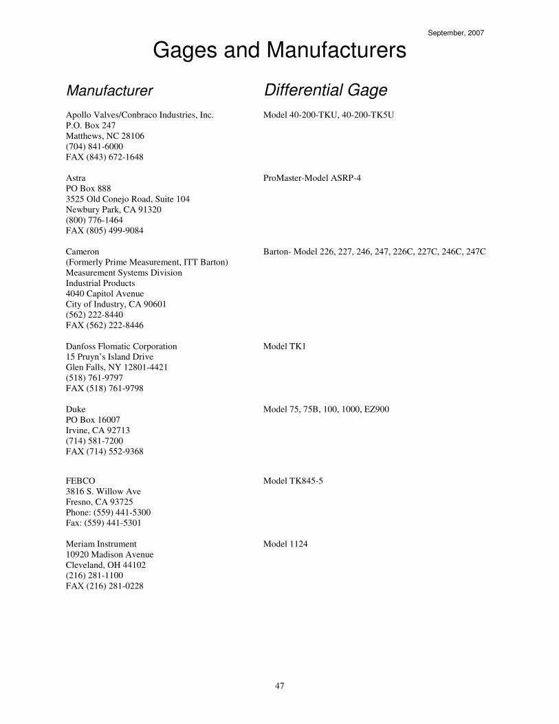
47
September, 2007
Gages and Manufacturers
Manufacturer Differential Gage
Apollo Valves/Conbraco Industries, Inc. Model 40-200-TKU, 40-200-TK5U
P.O. Box 247
Matthews, NC 28106
(704) 841-6000
FAX (843) 672-1648
Astra ProMaster-Model ASRP-4
PO Box 888
3525 Old Conejo Road, Suite 104
Newbury Park, CA 91320
(800) 776-1464
FAX (805) 499-9084
Cameron Barton- Model 226, 227, 246, 247, 226C, 227C, 246C, 247C
(Formerly Prime Measurement, ITT Barton)
Measurement Systems Division
Industrial Products
4040 Capitol Avenue
City of Industry, CA 90601
(562) 222-8440
FAX (562) 222-8446
Danfoss Flomatic Corporation Model TK1
15 Pruyn’s Island Drive
Glen Falls, NY 12801-4421
(518) 761-9797
FAX (518) 761-9798
Duke Model 75, 75B, 100, 1000, EZ900
PO Box 16007
Irvine, CA 92713
(714) 581-7200
FAX (714) 552-9368
FEBCO Model TK845-5
3816 S. Willow Ave
Fresno, CA 93725
Phone: (559) 441-5300
Fax: (559) 441-5301
Meriam Instrument Model 1124
10920 Madison Avenue
Cleveland, OH 44102
(216) 281-1100
FAX (216) 281-0228

48
September, 2007
Gages and Manufacturers
Manufacturer Differential Gage
Mid-West Instrument Model 830, 835, 845-2, 845-3, 845-5
6500 Dobry Drive
Sterling Heights, MI 48314
(810) 254-6500
FAX (810) 254-6509
Watts Regulator Company Model TKDR, TKDP, TK99D
815 Chestnut Street
North Andover, MA 01845
(508) 688-1811
FAX (508) 794-1848
Wilkins Regulator Company Model TG-3, TG-5
1747 Commerce Way
Paso Robles, CA 93446
(805) 238-7100
FAX (805) 237-3969 September, 2007

49

50
Appendix E
Assembly Test Report Form

51
Backflow Assembly Test Report
Water System
Name:
File No.:
Location of Assembly:
Owner of Assembly:
Address: City: State: Zip:
Size of Assembly: Model No.: Serial No.:
Name of Assembly Manufacturer:
I
N
T
I
A
L
Check Valve #1
Check Valve #2
Differential Pressure
Relief Valve
Pressure Vacuum
Breaker
RP
PSI Across _______
PSI Across _______
Opened at _____#
Opened Under 2# or
did not open
AIR INLET:
Opened at ______ #
Opened Under 1# or
did not open
DC
Closed Tight Leaked
Closed Tight
Leaked
CHECK VALVE:
Closed Tight Leaked
R
E
P
A
I
R
S
Cleaned Replaced:
Disc
Spring
Guide
Pin Feather
Hingepin
Seat
Diaphragm
Other (describe)
Cleaned Replaced:
Disc
Spring
Guide
Pin Feather
Hingepin
Seat
Diaphragm
Other (describe)
Cleaned Replaced:
Disc
Spring
Diaphragm
Seat(s)
O-ring(s)
Module
Other (describe)
Cleaned Replaced:
Air Inlet Disc
Air Inlet Spring
Check Disc
Check Spring
Other (describe)
FINAL TEST
PSI Across
Closed Tight
PSI Across
Closed Tight
Opened at #
Reduced Pressure
Satisfactory
Initial Test By: Certification No.: Date:
Repaired By: Date:
Final Test By: Certification No.: Date:
This assembly's INITIAL TEST performance was: Satisfactory Unsatisfactory
This assembly's FINAL TEST performance was: Satisfactory Unsatisfactory
I certify the above test has been performed and I am aware of the final performance.
BY: ______________________________________________ Assembly Owner Representative
Distribution: White - Assembly Owner Pink – Tester Canary – Water Utility