Cross-Barrel Temperature Difference Due to Wall Thickness ... · PDF fileAD-A262...
69
AD-A26 2 5O9 !!l~l•!il,,t 11 ARMv RESEARCH LABORATORY Cross-Barrel Temperature Difference Due to Wall Thickness Variation Nathan Gerber Mark L. Bundy ARL-TR- 100 March 1993 DTJ_ E I ECT EF'-0 Reproduced From MR 0M 1 BeSt Available Copy APPROVED R PUBUC RELEAS DISTRRII•LON IS UNUMITrE. 93-06786 98 4 01 04.8!+ Soooo90 141
Transcript of Cross-Barrel Temperature Difference Due to Wall Thickness ... · PDF fileAD-A262...
AD-A26 2 5O9!!l~l•!il,,t 11
ARMv RESEARCH LABORATORY
Cross-Barrel Temperature DifferenceDue to Wall Thickness Variation
Nathan GerberMark L. Bundy
ARL-TR- 100 March 1993
DTJ_E I ECT EF'-0
Reproduced From MR 0M 1BeSt Available Copy
APPROVED R PUBUC RELEAS DISTRRII•LON IS UNUMITrE.
93-06786
98 4 01 04.8!+Soooo90 141
NOTICES
Destroy this report when it is no longer needed. DO NOT return it to the originator.
Additional copies of this report may be obtained from the National Technical informationService, U.S. Department of Commerce, 5285 Port Royal Road, Springfield, VA 22161.
The findings of this report are not to be construed as an official Department of the Armyposition, unless so designated by other authorized documents.
The use of trade names or manufacturers' names in this report does not constituteindorsement of any commercial product.
Accesion ForNTIS CRA&Il •DTIC TABUnannouncedJustification
By.......Distribution I
Availability Codes
Avail and orDist Special
P -
FomApprovedI:ErPORT. DOCUMENTATION PAGE JM No. 0704-0188"uIic redoortng burden for this collection of ~inornmat *m etnaatoaea Iouo'feore.ncdngteteirrmwIng nnt ruct Pont sea rchng ellisting data source&,gathering and Maintaining the data ne~ed . and corrotein "an r""e, n the(Old onf infrmnation Send commncrts regarding this bulrden estimate or any other awedt of thismcoileleton of nformnatoft. includjIng suggestionior reducing ,i buirden. to Washington NeadauartfirsServices, Directorate fe, information Opiffations and Report%, 12 IS JeffiersoniDavis highway. Suite 1204, Arlington. VA 22202-4302. and to thme Office of Management and Budget. Paperwork Aeduc-tion Project (0704-019881,Yashinglon, DC 20S03
1. AGENCY USE ONLY (Leave blank) 2. REPORT DATE 3. REPORT TYPE AND DATES COVERED1 March 1993 Final, June 91-Juiy 92
4. TITLE AND SUBTITLE 5. FUVO'ING NUMBERS
Cross-Barrel TeMperaturo Difference Due to Wall Thickness Variation PR: 1L162618AH50
C. AUTHOR(S)
Nathan Gerber and Mark L Bundy
7. PERFORMING ORGANIZATION NAME(S) AND ADDRESS(ES) III PERFORMING ORGANIZATIONREPORT NUMBER
U.S. Amry Research LaboratoryATTN: AMSRL-WT-PBAberdeen Proving Ground, MD 21005-5066
9. SPONSORING/ MONITORING AGENCY NAME(S AND ADDRESS(ES) 10., SPONSORING /MONITORINGAGENCY REPORT NUMBER
U.S. Army Research Laboratory ALT-0ATTN: AMSRL-OP-CI-B (Tech Lib) ALT-0Aberdesn Proving Ground. MD 21005-5066
11. SUPPLEMENTARY NOTES
12s. CISTRIBUTION / AVAILABILITY STATEMENT 12b. DISTRIBUTI,3fl CODE
Apprved for pubric release; rd"stribution Is unlimnited.
13. ABSTRACT (Maximum 200 words)
Advances In manufacturing techniques have reduced, but not eliminated, cross-barrel wail thickness variationIn the production of gun barrels. Structurally, these small variations will niot appreciably diminish the strength ofthe barrel, and ar-e, therefore, not a firing safety concern. However, even small variations will produce cross-barrel temperature differences that can Increase with the nurnber of rounds fired, and thereby produce thermaldistortion of the barrel, which degrades gun accuracy. This Investigation presents a theoretical (finite difference)analysis of the cross-barrel temperature difference expected to occur as a result of typical and atypical walithickness variation In production-line guns. The results Indicate that typical bt rrels will not Incur an appreciablethermal bend due to wall thickness variation. However, current manufacturing h.'erances would allow an atypicalbarrel to be fielded that could undergo significant thermal distortion due to a cross-barrel temperature differencecreated by asymmetric wall thickness.
14. SUBJECT TERMS 15. NUMBER OF PAGES
gun barrel heating, finite difference theory, wall thik~ness variation, cross-barrel 16. PIECDtemperature difference, M256 120-mm gun barrel, repeated firing, gun barrels17. SECURITY CLASSIFICATION III. SECURITY CLASSIFICATION 19. SECURITY CLASSIFICATION 120. LIMITATION OF ABSTRACT
OF REPORT OF THIS PAGE J OF ABSTRACTUNCLASSIFIED UNCLASSIFIED I UNCLASSIFIED UL
NSN 7540-01-280-5500 Standard Form 298 (Rev. 2-89)!POescnbj by A14SI Std Z391.t

INTENTIONALLY LEFT BLANK.
TABLE OF CONTENTS
* Page
LIST OF FIGURES............................................. v
ACKNOWLEDGMENTS......................................... v~i
1. INTRODUCTION..............................................1I
2. THE GUN BARREL MANUFACTURING PROCESS ...................... 2
3. THE HEATING MODEL................... I...................... 6
4. FORMULATION OF THE PROBLEM................................ 7
4.1 Statement of Problem........................................ 74.2 Special Form of Solution ...................................... 114.3 Transformed Radial Coordinate................................. 124.4 Wall Temperatures ......................................... 12
5. INPUT DATA ................................................ 13
6. FINITE-DIFFERENCE CALCULATION............................... 16
7. COMPUTATIONS.............................................18s
8. CBTD DUE TO WALL THICKNESS VARIATION IN PRODUCTION LINE.MIAl GUN BARRELS....................................... 25
9. REFERENCES .............................................. 29
APPENDIX A: STATEMENT OF PROBLEMS IN 4. t VARIABLES........ 31
APPENDIX B: COEFFICIENTS IN EQUATIONS 20 AND 21.........35
APPENDIX C: TIME SCALE ..................................... 41
APPENDIX D: ANALYTICAL MODEL OF COOLING ..................... 45
LIST OFSYMBOLS ........................................... 51
DISTRIBUTION LIST .......................................... 55
1-:_
. ................
INTENTIONALLY LEFT BLANK.
III
LIST OF FIGURES
FBure Page
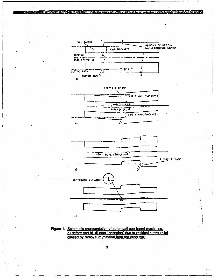
1. Schematic representation of outer-wall gun barrel machining, 9) beforeand b)-d) after "springing" due to residual stress relief caused byremoval of material from the outer wall ............................ 3
2. Centerline deviation and wall thickness variation (right side minus left)for an M256 barrel, serial number 4251 ........................... 5
3. Centerline deviation and wall thickness variation (top minus bottom)for an M256 barrel, serial number 4251 ........................... 5
4. Transverse cross section of a gun barrel of nonuniform thickness, viewed Ina) and b) from the muzzle, and in c) from an oblique angle of the breech... 8
5. Single-round histories of T3 at inner and outer walls at two axialstations .................................................... 14
6a. Bore gas temperature histories at two axial stations .................... 15
6b. Convective heat transfer coefficient histories at inner wall of gun barrelat two axial stations ......................................... 15
7. Single-round histories of unperturbed temperature, T1, at three radiallocations .............................................. 19
8. Axisymmetric temperature histories on Inner and outer walls at z = 4.30 m,slow rate-of-fire ............................................. 19
9. Histories of AT, and ATo at z = 4.30 m, slow rate-of-fire ................. 21
10. Histories of AT1 and AT, at z - 4.30 m. fast rate-of-fire .................. 21
11. Histories of AT, and AT, at z = 2.78 m, fast rate-of-fire .................. 22
12. Histories of AT, and ATo at z = 3.95 m, firing scenario of Table 1,with cooling to environment ............................... ZS
13. Histories of AT1 and AT, at z - 3.95 m for an adiabatic outer wallcondition, firing scenario of Table 1 .............. ............... 24
14. Worst case CBTD for M256 gun barrel, tial number 4251 (typicalproduction line barrel) ........................................ 26
D-1. Comparison of AT, cooling histories for analytical model and numericaloutput (ta= 1,000 s) .................. ..................... 49
v
INrENTIONALLY LEFT BLANK.
vI
,--..... /-
ACKNOWLEDGMENTS
The authors would like to thank the following U.S. Army Research La.oratory* (ARL)
co-workers: James Bradley (PFD) for programming the finite-difference solution;
John Petresky (contractor) for his help in ge;l*g the program to run on the ARL
supercomputer; Emily Hsi (contractor) for graphical sketches; and Paul Conroy and George
Keller (PFD) for interior ballistic3 input and funding, respectively. They would also like to
thank Brtt Overocker, Watervllet Arsenal, for his input on the gun marufactbring process.
Note: The U.S. Army Ballistic Research Laboratory (BRL) was deactivated on 30 September 1992 and subsequently
became a part of ARL on 1 October 1992.
vii
INTENTIONALLY LEFT BLANK.
viii
1. INTRODUCTION
Outwardly, gun barrels appear axially symmetric. Yet, when a gun is fired, the barrel
temperature rise is typically not axisymmetric. For instance, instead n f the terr-,-7ture rising
uniformly at a given axial location, firing may elevate the barrel temperature more on the left
side than on the right in one area, and more on ihe bottom than the top in another area, or
vice versa. Any cross-barrel temperature difference (CBTD) will produce a cross-barrel
thermal expansion difference that causes off-axis bending of the barrel during firing. This
thermal bending/distortion decreases tank gun accuracy and is, therefore, a situation to be
avoided. (The CBTD referred to here, AT., is defined as the difference between the
temperatures at the two intersection points on the outer wall of the barrel formed by a line in
the transverse plane passing through the center of the bore. A similar CBTD for the inner
wall, AlT, will be introduced later. The difference between the lengths of the two segments
between Inner and outer walls formed by this same line Is called the "wall thickness
variation.")
The terms "bore centerline" (or "centerline") and "Centedine deviation" are now introduced.
Consider an infinite set of planes intersecting the gun barrel so that the inner wall forms a
circle in each plane. Then the locus of the centers of these circles is the three-dimensional
centerline curve. When there Is no bending of the gun tube, the centerline is straight,
coinciding with the rotation axis of the machining tool. In a given longitudinal plane through
the rotation axis, the centerline trace is a curve that deviates slightly from the rotation axis; the
amount of displacement (normal to the rotation axis) is the centerline deviation.
The source of CBTD has long been a topic of discussion/speculation (Manaker and
Croteau 1976; Bundy 1987a, 1987b). For example, in the case-study of Bundy (1987b), test
results Indicated a possible correlation Detween CBTD and the centerline deviation. (In a
plane passing through the rotation axis, the temperature rise was generally greater on the
same side of the rotation axis as the centerlire deviation.) Apparent correlations and
speculations aside, we shall show that wal! thickness variation will indeed produce CBTD.
To predict the CBTD due to wall thickness variation during firing, we shall solve the time-
dependent, two-dimensional (radial and circumferential) equations that govern heat transfer
!
into, through, and out e gun barrel by the method of finite differences. Primarily, results
will be computed for .,fic, but typical, production-line M256 120-mm gun barre! and for a
service-acceptable, yet atypical, production-line barrel.
To provide some understanding of the origins of wall thickness variation, we shall briefly
describe the gun barrel manufacturing process. It will become apparent that wall thickness
variation and centerline deviation are related, to some degree, as a consequence of the
manufacturing process. Thus, the apparent correlation nojed by Bundy (1987b) botween
CBTD and centerline deviation may--more fundamentally--be a correlation between CBTD
and wall thickness variation.
2. THE GUN BARREL MANUFACTURING PROCESS
Much effort has been devoted in the manufacturing process of large-caliber guns to
minimizing lateral wall thickness variation. In general, circularity of the inner and outer surface
is not the problem--ccncentricity is. That is, wall thickness variation is caused primarily by
the non-alignment of the axes of rotation of the inner and outer surfaces of revolution during
their machining. It is conjectured that this comes abjut as follows.
After removal from the forge and heat treatment (to relieve residual forging stress), the
barrel is ready to be "finished" (a multistep process to bring the rough forged barrel to its final
design/drawing specifications). The inner surface is finished first, which means that it is
bored, honed, swaged, and thermally treated to help relieve swaging stress, then bored again,
and honed again. It has a relatively straight centerline before finishing work is begun on the
outer surface. Initially, the axis of rotation for machining the outer surface is the same as the
axis of the inner surface (i.e., the bore centerline, see Figure la). However, when metal is
removed by turning down the outer surface, It relieves non-uniform residual swaging stress,
which causes the Uarrel to "spring" or bend off-axis. Whenever and wherever #his happens
during machining, it misaligns the bore centerline from the rotational L.XIs of the yet-to-be
finished outer surface, and thus produces both lateral wall thickness variation and bore
centerline deviation in the gun barrel. As illustrated in Figure lb, the wall thickness variation
will be twice the centedine deviation at-and only at-the place where material is being cut,
2
/(
GUN BARREL ____________________
............ REGIONS OF RESIDUALWLL THICKNE!S MANUFACTUJRING STRESS
ROTATIONAXIS AN --- 4 - - - - - - -
BORE CENýTERLINE
.........AI T ... - ..TO0IECUTCUTTING PAT
0)CUTTING TOOL 2
STRESS I RELIEF
SIDE 2 WALL THICKNESS1
-ROTATION 'AXIS
loRE CENTERLINE
SIDE I WALL THICKNESS;
NE-W BO-RE CEN-TE-RLItifSTRESS 2 RELIEr
C)
CENTERLINE DEVIATION
d)
Figure 1. Schemaflc reviresentation of outer-wall-gun barrel machining.a) before and b)--d) after asornainoo due to residual stress reliefcausedf by removal of material from the outer wall.
since stress relief at a new cut site will change the centerline deviation everywhere along the
barrel including previous cut sites (Figure Ic). Furthermore, it is common practice to attempt
to mechanically straighten a gun barrel (with a hydraulic press) during or after machining.
Nevertheless, we might expect that some residual correlation between centerline deviation
and wall thickness variation will remain along the finished barrel, as illustrated in Figure 1d.
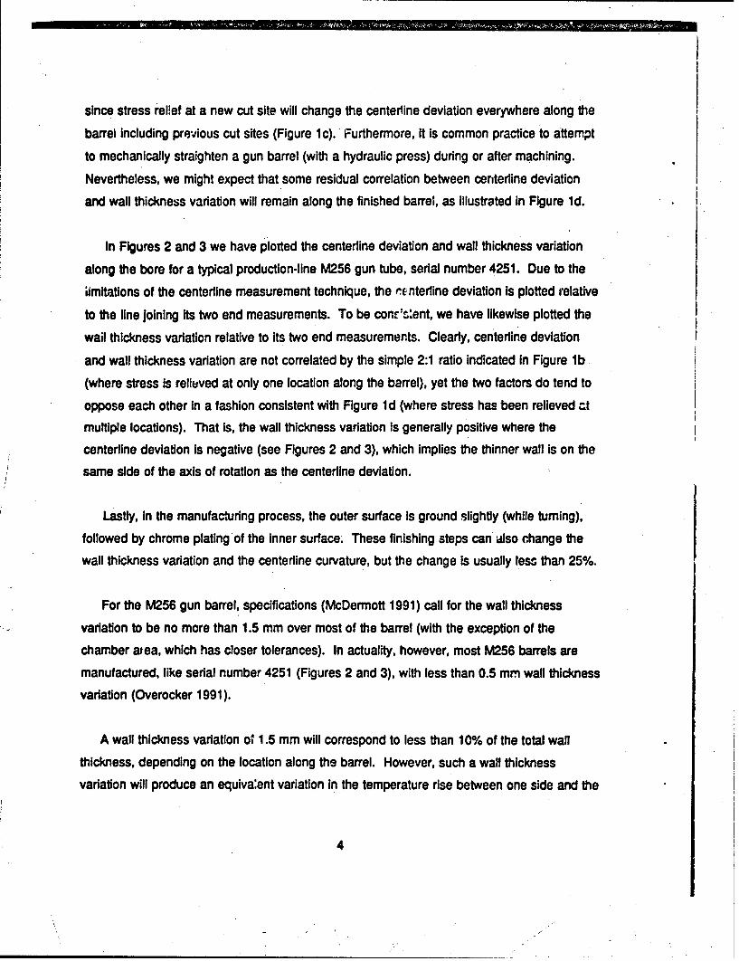
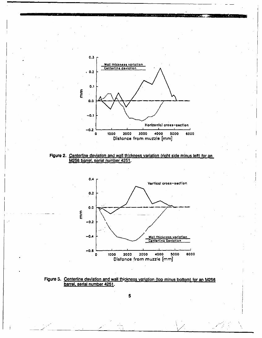
In Figures 2 and 3 we have plotted the centerline deviation and wall thickness variation
along the bore for a typical production-line M256 gun tube, serial number 4251. Due to the
imitations of the centedine measurement technique, the rnterine deviation is plotted relative
to the line joining its two end measurements. To be cons.•ent, we have likewise plotted thewail thickness variation relative to Its two end measurements. Clearly, centerline deviation
and wall thickness variation are not correlated by the simple 2:1 ratio indicated in Figure lb
(where stress is reliuved at only one location along the barrel), yet the two factors do tend to
oppose each other in a fashion consistent with Figure Id (where stress has been relieved atmultiple locations). That Is, the wall thickness variation Is generally positive where the
centerline deviation is negative (see Figures 2 and 3), which implies the thinner wall is on thesame side of the axis of rotation as the centerline deviation.
Lastly, in the manufacturing process, the outer surface is ground slightly (while turning),
followed by chrome plating of the inner surface. These finishing steps can also change thewall thickness variation and the centerline curvature, but the change is usually less than 25%.
For the M256 gun barrel, specifications (McDermott 1991) call for the wall thickness
variation to be no more than 1.5 mm over most of the barrel (with the exception of the
chamber area, which has closer tolerances). In actuality, however, most M256 barrels aremanufactured, like serial number 4251 (Figures 2 and 3), with less than 0.5 mm wall thickness
variation (Overocker 1991).
A wall thickness variation of 1.5 mm will correspond to less than 10% of the total wall
thickness, depending on the location along ths barrel. However, such a wall thickness
variation will produce an equiva:ent variation In the temperature rise between one side and the
4
0.3
Wall thickness variotionCenterline deviction0.2 .0 . ....c•.'. t.e.. L . •.e.. .... ..... .............
0.1
E 0.0 . ......... -
HorizontGc cross-section
-0.2 .I I I
0 1000 2000 3000 4000 5000 6000Distance from muzzle [mm]
Figure 2. Centerline deviation and wall thickness variation (right side minus left) for anM256 barrel, serial number 4251.
0.4Vertical cross-section
0.2
0.0 .-.-...
-0.2 :.. ."tl
-0.4 e Wall thickness variation
.Cnterline Deviation
-0.6 .
0 1000 2000 3000 4000 5000 6000
Distance from muzzle [mm]
Figure 3. Centerline deviation and wall thickness variation.(top minus bottom) for an M256barrel, serial number 4251.
5
/ V
other. For instance, if the nominal barrel temperature rise from firing a round is 100 C at alocation where the wall thickness varies by 10% between one side and the other, then theCBTD will be approximately 10 C at this site. This CBTD will increase if the gun is firedrapidly. For reference, Bundy (1987b) showed that a 20 to 3" C change in the CBTD over arelatively short length of the barrel (<1 m) will produce a muzzle angle change of severaltenths of a miliradian. We shall show that almost any *fast" rate of fire will yield a CBTD ofseveral degrees if the wall thickness variation approaches the maximum allowed by currentmanufacturing guidelines.
3. THE HEATING MODEL
We shall compute the CBTD for multiple firings by employing an extension of the model
used In Gerber and Bundy (1991). The following assumptions apply here:
(1) Temperature gradients In the logtdnldirection are neglected in comparison withthose In the radial direction. (The longitudinal axis Is taken to be a locally straightsegment at the transverse plane brider consideration.)
(2) Axisymmetric heat input is assumed, and gravity effects in the cooling processare neglected.
(3) Feedback of barrel heat to flow Ir the gun bore is neglected, so that the same boretemperature and convective heat transfer coefficient histories (for a single round)furnish the Input data for every round calculated.
(4) Friction heating is neglected.
(5) Thermal expansion of the barrel is not considered to have an effect on the heattransfer process.
(6) The thermal conductivity, k, the specific heat, cp,, and the density, p. of themetal are constants (see Chapter 5).
6
(7) The offset distance (E) between the axes of the inner and outer walls is very
small compared to the radii of the walls themselves. For example, in the
extreme case for the M256 120-mm gun, the axes displacement would be less
than 1 mm, while the inner radius of the barrel would be at least 60 mm.
4. FORMULATION OF THE PROBLEM
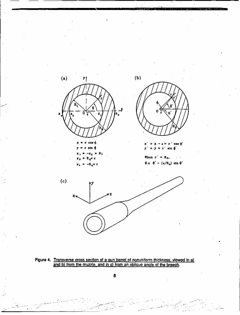
4.1 Statement of Problem. We state our problem In terms of cylindrical coordinates r,*,
and z. Figures 4a and 4b show the transverse plane viewed from the muzzle. The axial
coordinate z is taken to be zero at the gun's breech (Figure 4c). The z-axis coincides with the
centerline of the bore (i.e., the axis of the inner wall surface), which intersects the r, * plane at
the origin, 0. (Note, the right-handed coordinate system that we have chosen is consistent
with the reference system of most Interior ballistics models. However, It differs from the so-
called gunner's coordinate system, which chooses ft 3 positive x-axis to lie on the gunner's
right, which Is our negative x-axis.) The radii of the inner and outer walls, referenced to their
Individual axes of rotation, are R, and Ro, respectively. In our model we assume that the axis
of the outer wail Is displaced to the right of the axis of the inner wall by a distance E to
simulate the Imperfection of manufacture. The radius of the outer wall relative to the origin
will be designated by r = ro (*).
At a given axial location, z, the gun barrel temperature, "(r,$,), is determined by the
following differential equation of heat conduction for a stationary, homogeneous, Isotropic solid
with no internal heat generation (Holman 1981, p.6):
$Tlar + (1Ir)aT/ar (11r 2 )a2Tla02 . (lla)Tiat, (1)
where t = time from the Initiation of the first round. The constant a w k(p cp) Is the thermal
diffusivity.
Let T. designate the ambient temperature of the atmosphere (assumed to be constant).Then the initial condition is
7
( a)(b)
x = r cost x -- x---rcos•y = r sin t y' y r' sin t,
21 -- - = Ri
X=3 R+ t When r' Ro.
4 = -o+ - (tIRo) sin '
(•) y
x
Figure 4. Transverse cross section of a gun barrel of nonuniform thickness, viewed In a)
and b) from the muzzle, and in c) from an oblique angle of the breech.
8

T(ro) - T.. t - 0, R, < rmro ($) (z const). (2)
The boundary conditions at the inner and outer walls are obtained by Newton's iaw of
cooling (see, e.g., Ozisik [1968]). The axisymmetric boundary condition at the inner wall is
k a TlM r- hgT, -hgTg r, R, t>O (z, cons!), (3)
where T(Ltz) is the cross-sectional average temperature of the flow In the bore, and hV(t,z) is
the coefficient of heat bansfer between the gas-particle mixture In the bore and the Inner wall
of the barrel. Tg(t,z) and h(t, z) are known from Interior ballistic computations and thus
constitute Input.
The outer wall boundary condition introduces azimuthal variation into the problem. The
outer wall equation Is
2r. [Ro - C 2 sin2 0]112 + pcos.
We restate one of the basic assumptions,
S<< R1, Ro (4)
and retain only terms through first order in e. Then for the outer wall,
ro-Ro+ecos . (5)
The boundary condition here, which includes both convective and radiative cooling
(Ozisik 1968, Equations 1-28 and 8-137c; Gerber and Bundy 1992, Equation 4), is
-kaT18ln h..(T-T.j + Fa(T4 - T.) r ro ,t> 0 (z- const), (6)
where aT•7an Is the component of grad Tnormal to the barrel surface, and h. - h. (z) is the
coefficient of convective heat transfer between the barrel wall and the surrounding
9
.----------------------------------------
atmosphere. F Is the radiation interchange factor between the barrel outer wall and the
environment (in our case, we assume F = 0.95), and a is the Stefan-Boltzmann constant
[= 5.669 x 10"l J/(r 2 s K4)].
A unit outward vector normal to the outer wall (correct through 0(e)) is U = [1, e(1/r)sin 4];
grad T= [Ja77r, (1/l) aTlo]. Then, aT/an =jUn grad Tin Equation 6. On the line
r- + e cos 0, Equation 6 becomes
- k [aT/ar+ (dr 2 )sin X97a41] - h.(T - T.) + Fa(T4 - 7T.) (7)
Applying the expansion
F,(r Ro + E cos *) = Fn(Ro) * (a Fnar)R 0e cos €+ O(C)
(where F. Is any function of r) to Equation 7 leads to
-k + (2T) eTcos, +-._.sine .(aT] h.T -T.. e cos.)T +1 .r ar2)R
Fe[T4 - T. + 4 e T3(aT/ar)cos + 0( C) at r - Ro. (8)
To retain linearity In the outer wall boundary condition, we apply the reasinable approximation
that I Tm"' - Tm I <<Tm at r= R., Here the superscript m + 1 refers to te current timestep
of calculation, while m denotes the immediately preceding time step when T is known. Thus,
-(4(T N1 .'I7J - 3(TN, 1)4
which is linear in Tki, I The subscript NI + 1 denotes r= Ro.
10
I IllI ' - --- - -
4.2 Speclal Form of Solution. When a solution of the form*
T Tl(rt) + ecos T3 (rt) (9)
--- is substituted Into Equations 1, 2, 3, and 8, the 2-D problem is reduced to two
one-dimensional (1 -D) problems by collecting terms for each power of e cos. The
statements of these two problems now follow:
(1/a) aT1/at, a2T1/ar2 + (l/r) aTtlar (10a)
T (,t). 0 T". t - 0, Ri < r:5 R, (10b)
•,k aT1/ar .hg(T1 Tg) r. Ri, t > 0 (10Oc)
: :" ~~~~k T1/8a r + [ h. + 4 Fa l) I +1.h " Fa T"4. + 3( Tm)41
r.Ro. t >0, (1lOd)
and m3
(11/a) aT3/at. aT 3/ar 2 + (l/r) aT3/ar - (1/r2)T 3 (Ta)
•T3 Vr,t)- 0 t- 0, Rj!S r<5 Ro (111b)
k aT3 1ar, - hgT 3 r Ri, t > 0 (11c)
8 T3/ar + (h. + 4FoT•I) T3/k M WTI) r. Ro, t > 0, (11d)
where
"The choice of T3 instead of T2 for the perturbation was made to maintain consistency with the nomenclature of thecomputer program.
S~11
• . - -- - .•. ., . . . .. •_ . -
W(T1 ) m -a2T Iar 2 - (h.. + 4FuT )(aT1 /ar)/k
r =, Ro t- tm*l. (12)
The first problem is the axisymmetric problem previously solved (Gerber and Bundy 1991,
1992). The second problem is coupled to the first through the outer wall boundary condition
(Equation I1d). The function M T1 ') is a known quantity at the time of solution, so that the two
problems can be solved in tandem.
4.3 Transformed Radial Coordinate. We Introduce a transformation, as In Gerber and
Bundy (1991, 1992),
r r(4) (0 < , <5 1), (13)
so that the constant Increment ,g will cluster the nodal points closely together near the Innerwall, where Tl(rt) gradients are largest, and spread them out awa) from there. We define the
transformation in the following two steps:
S(P)-yE+(1 -() (<Ocy1, 13>2), r D; +Ri, (14)
where D Ro - R,, and -f and 13 are chosen constants. We have used y = 0.092, 13=2.25.
Note that r = Ri, Ro correspond to =0, 1, respectively. The actual computations are then
caried out in the (E, t space; a restatement of the problems in 4 and t is provided in
Appendix A.
4.4 Wall Temperatures. The wall temperatures are of particular interest, especially that ofthe outer wall, which is the most easily measurable. At the inner wall,
Ti,. T (r - R,) - T1 (Ri, t) + t cos* T3 (Ri, t). (15)
At the outer wall,
Tm T(r- Ro + ecoso) - T1 (R~t) + ecos [aT1/ar+ T3]r. R,0 (16)
where (aTlar) at r= R. is given by Equation 1Od (or Equation B-1 la).
12
A diameter cutting across the gun barrel is property described by the angles 41 = and
' -*i €1+ x (see Figure 4b). Since€ =€ + 0 (e) (Figure 4b), 0 may be replaced by,' in
Equations 15 and 16 withcut changing the accuracy of the approximation.
Equation 9 Indicates that the ent~re azimuthal variation of temperature is contained in the
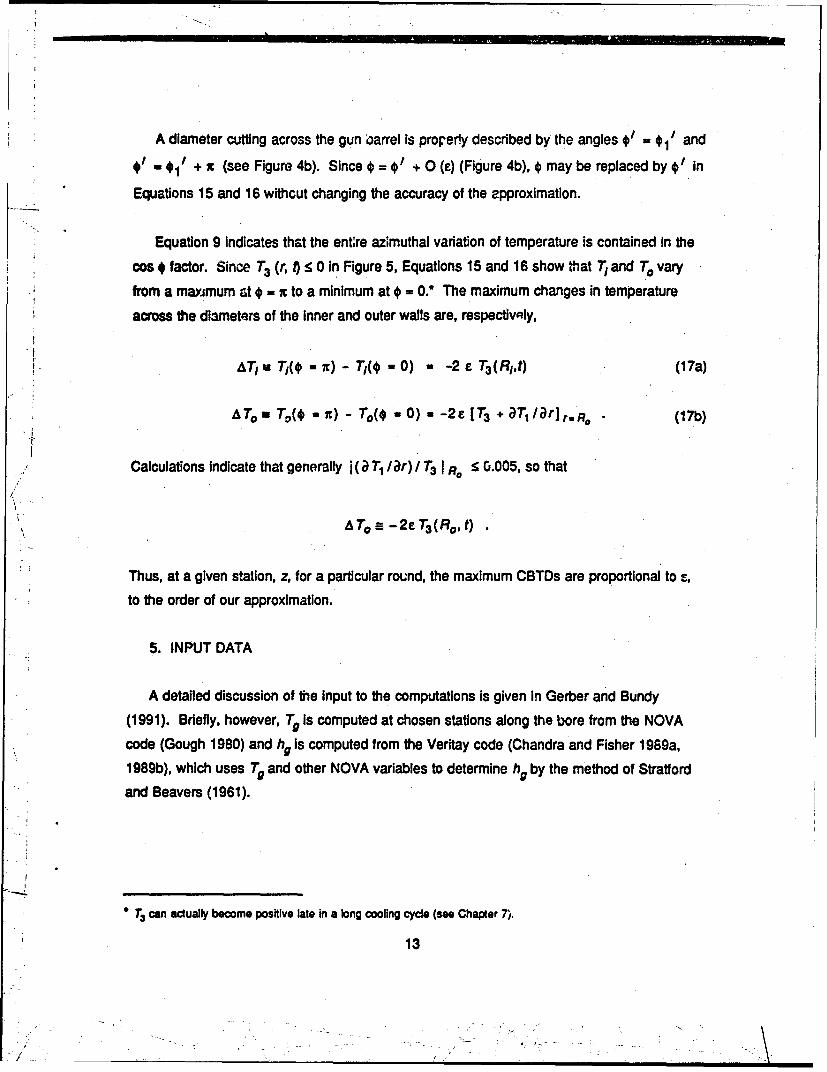
cos # factor. Since T3 (r, t) < 0 in Figure 5, Equations 15 and 16 show that T, and TO vary
from a maximum at * = x to a minimum at = 0.* The maximum changes in temperature
across the diameters of the inner and outer walls are, respectivaly,
A&Tj, T1(* = - Tj(ý -0) -2 e T3 (RIt) (17a)
ATo. Tv( it) - To( -0) - -2E [T3 + aT/jar]r-R. (17b)
Calculations indicate that generally j(a) T1 lar) l T3 I R : 0.005, so that
ATo---2eT 3 (Ro,t)
Thus, at a given station, z, for a particular round, the maximum CBTDs are proportional to s,
to the order of our approximation.
5. INPUT DATA
A detailed discussion of the input to the computations is given in Gerber and Bundy
(1991). Briefly, however, T. is computed at chosen stations along the bore from the NOVA
code (Gough 1980) and h. is computed from the Veritay code (Chandra and Fisher 1989a,
1 989b), which uses T. and other NOVA variables to determine h. by the method of Stratford
and Beavers (1961).
* T3 can actually become positive late in a long cooling cycle (see Chapter 7).
13
I ~-~___,
200" '-.- .. ..... ... .......................... "" i............. .. ..
.......... z 24.30 m
I J
S-600 /r~in)
, 0.001m
-800 t i
0 20 40 60 80 100 120 140 160 180
t [si]
Figure 5. Sinmle-round histories of _3 at Inner and outer walls at two axial stations.
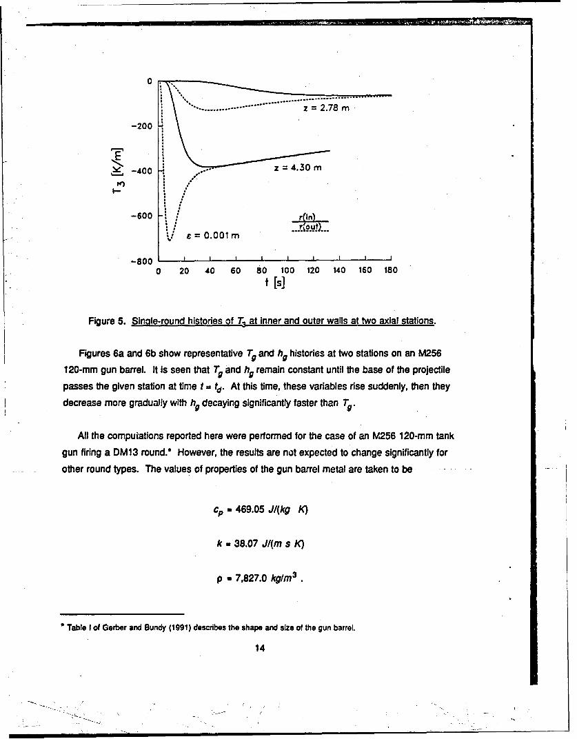
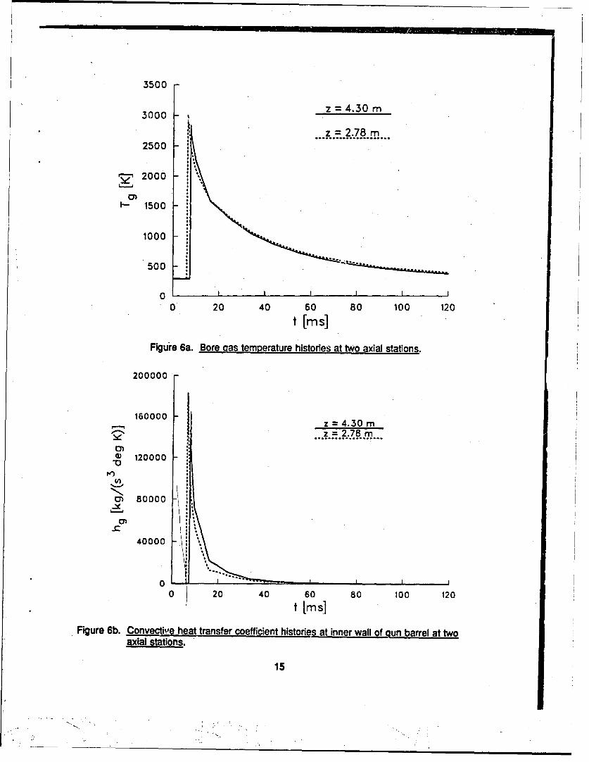
Figures 6a and 6b show representative Tg and hg histories at two stations on an M256
120-mm gun barrel. It is seen that T and hg remain constant until the base of the projectile
passes the given station at time t = td. At this time, these variables rise suddenly, then they
decrease more gradually with hg decaying significantly faster than T7.
All the computations reported here were performed for the case of an M256 120-mm tank
gun firing a DM13 round.* However, the results are not expected to change significantly for
other round types. The values of properties of the gun barrel metal are taken to be
cp 469.05 J/(kg K)
k - 38.07 J/(m s K)
p - 7,827.0 kg/m3 .
Table I of Gerber and Bundy (1991) describes the shape and size of the gun barrel.
14
3500
3000 z = 4.30 m
z = 2.78 mo............o..•o.....
2500
2000
I-- 1500
1000
500
00 II I I I I
0 20 40 60 80 100 120t [ims]
Figuie 6a. Bore gas temperature histories at two axial stations.
200000
160000 - z = 4.30 m__Z_=4.30_m
2' z = 2.78 mSo~...................
(" 120000
C) 80000_ Ij
-I*
0 -
0 i 20 40 60 80101240000 :20
t [ms]
Figure 6b. Convective heat transfer coefficient histories at inner wall of gun barrel at twoaxial stations.
15
The diffusivity Is thus
a 1.03698 x 10"5 ;,72/s.
The ambient condition constants are
T.- 294.4 K (unless otherwise stated)
h.. 6.0 kg/(s 3 K).
The above value of c0 was measured in 1990 by Joseph Cox, Benet Weapons Laboratory, for
M256 gun barrel steel (assumed to be ASI 4340) at 295 K. The values for k and p were
obtained from Talley (1989) for 4335 steel. The value for h. was obtained from experiments
conducted by Bundy on a shrouded M256 barrel.
6. FINITE-DIFFERENCE CALCULATION
For the finite-difference calculations, the interval 0 :5 4 s 1 (corresponding to R1 < r : R.) is
divided by equally spaced nodal (or grid) points into NI subintervals. The constant ,
Increment Is AF = 1/NI, and location of the nodes is given by t= (j- 1) A (J= 1, 2,...N1+1).
Derivatives at node jare :,pproximated as follows (for H = T1, T3):
(a H/')j - (-3 Hji+ 4-Hj 1 - Hi2)/(2 A4) (j-1) (18a)
(aH/4)j- (H., 1 - Hi1)/( 2 At) (I - 2,...,NI) (18b)
(aH/at)j,, (Hj. 2 -4Hj,. + 3Hi)I(2 At) (j- NI+ 1) (18c)
(aHI•o2 )j, (Hj- 1 -2Hj + Hj÷I)/(t) 2 (j-2,..., NI). (18d)
16
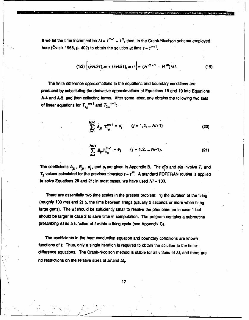
It we let the time increment be At tr'l - tm, then, in the Crank-Nicolson scheme employed
here (Ozislk 1968, p. 402) to obtain the solution at time t tn-1,
(1P2) (aHlat)tm+ (aH/at),m.I (Hml Hm)/at. (19)
The finite difference approximations to the equations and boundary conditions are
produced by substituting the derivative approximations of Equations 18 and 19 Into Equations
A-4 and A-5. and then collecting terms. After some labor, one obtains the following two sets
of lnear equations for Tn'"+ and T3#1.
NI• " dj(J. 1.2... NI.1) (20)
E OAp m, (N-1 NI MAjn~" .e / 1.2 .... NW÷). (21)
The coefficients Af. B19, dp, and e, are given In Appendix B. The cdjs and ejs Involve T1 and
T3 values calculated for the previous timestep t = tn. A standard FORTRAN routine is applied
to solve Equations 20 and 21; in most cases, we have used NI 100.
There are essentially two time scales In the present problem: 1) the duration of the firing
(roughly 100 ms) and 2) tj, the time between firings (usually 5 seconds or more when firing
large guns). The At should be sufficiently small to resolve the phenomenon in case 1 but
should be larger in case 2 to save time in computation. The program contains a subroutine
prescribing At as a function of t within a firing cycle (see Appendix C).
The coefficients in the heat conduction equation and boundary conditions are known
functions of t. Thus. only a single Iteration is required to obtain the solution to the finite-
difference equations. The Crank-Nicolson method is stable for all values of At, and there are
no restrictions on the relative sizes of At and A4.
17
7. COMPUTATIONS
We apply our numerical simulation to an investigation of the nonaxisymmetric barrel
temperature resulting from an Imperfect alignment of inner and outer wall barrel axes in an
M256 120-mm gun. Most of the CBTD plots that follow are shown for F, = I mm. The CBTD
for any other displacement Is readily obtained from these plots by multiplying the temperature
difference values by e In millimeters, since AT1 and A To are both proportional to e
(Equation 17).
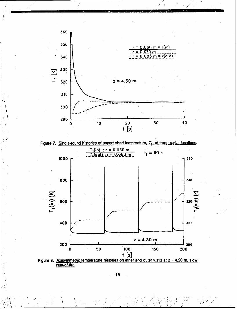
First we show results for a single round. Figure 7 presents unperturbed (axisymmetric)
barrel temperature histories, T1 , while Figure 5 includes the variation of the perturbation
function, T3 , at the same location. In both Instances, the functions tend to approach constant
values across the barrel In finite umes, as evidenced by the coalescing of the curves for the
Inner and outer walls. The time for the radial equilibration of T1 was referred to as the outer-
wall rise time, t,, In Gerber and Bundy (1991). For consistency, we shall continue to use this
designation here. Furthermore, we shall refer to the radial equilibration time of T3 as the rise
time t.3. There Is no exact criterion for defining rise time; an estimate can be made on the
basis of Inspection of the curves. For the example shown in Figures 5 and 7, ti3 Is
considerably larger then t.. The cos * factors In Equations 15 and 16 prevent circumferential
equilibration as long as T3 is non-zero. In Figure 5, T. appears to approach zero with time.
Next, we consider constant rate-of-fire. The first example (at z = 4.30 m) deals with slow
rate-of-fire (i.e., t. and t.3 < t, where t; is the time Interval between successive rounds). Here
tf- 60 s, tr - 26 s, and t.3 - 45 s. Rise times are essentially Independent of number of
rounds fired, but they depend on local barrel thickness. Figure 8 shows T1, the symmetric
part of T, at the Inner and outer walls as functions of time. The upward-facing spikes for the
Inner wall represent the rapid rise in temperature produced at the time of firing; the
succeeding rapid decline occurs when heat Input stops and heat is conducted into the Interior
of the barrel. It Is seen that T1 (R.) lags behind T1 (RF) In each cycle in the rise from Its pre-
firing value. This lag is a consequence of the time required for a significant effect of the
thermal disturbance applied at the Inner wall to reach the outer wall.
18
360
350 r = 0.060 m = r(in)r = 0.070 m
340 .. 0.0.3.m.. r,
rg 330
- 320 z =4.30 m
310
e , ......................................
2900 10 20 30 40
t[s
Figure 7. Single-round histories of unperturbed temperature, T1. at three radial locations.
T-(ln) :r= 0.060mT..T(ou., 0.0.oo8.3..m. tf =60 s
1000 360
800 340
600 ....... - 320" 2 ' 6 o 0 . ... .. .. .. ... .... .. . . . . . . 2
w..................
400 ," 300
z 4.30 m
200 -- 2800 50 100 150 200
Figure 8. Axisymmetric temperature histories on Inner and outer walls at z 4.30 m. slowrate-of-fire.
19
S/ . ,. _."7' N -,, , " . ,j: " " , ', . • . s ,-* •
-, i. . , \ "
Figure 9 presents the AT, and ATo histories for this same case. The inner and outer wall
curves coincide roughly over the latter portion of each firing cycle because the firing interval is
large enough so that radial equilibration is reached before the next round is fired. Except for
the first round, when AT/ = ATo = 0 prior to firing, there is a downward-facing spike at the inner
wall coinciding in time with the input of heat from the combustion. This is understandable;
heat flux from the bore gas to the barrel is proportional to (T. - T/), and thus, more heat will
be flowing Into the thicker, cooler side, raising T1 faster there than on the thinner, hotter side.
This will decrease AT, for an initial period of time. However, since the cooler side Is thicker,
the rise in T1 will eventually be less on that side, thus accounting for the overall positive AT,
following the Initial downward-facing spike.
For each round, the ATo will begin to rise after the heat pulse from the inner wall reaches
the outer wall on the thinner side (located at x4 = -Ro + e in Figure 4). The effect of the wall
thickness asymmetry is then propagated inward, and the time taken for the resulting
perturbation to spread to the inner wall accounts for the lag in Figure 9 of the rise of AT,
behind that in AT0. T(x4) and 7(x 3) (Figure 4) reach maxima because the energy input is
finite; ATo = T(x4) - 7(x3) eventually peaks and then decreases as the barrel cools and CBTD
equilibrates. At the inner wall, the heat perturbation due to the asymmetry is experienced at
x2 sooner than at x,; AT/ a T(x2) - T(x1) varies in a manner similar to that of ATo. its
amplitude in a firing cycle being less than or equal to ATo.
Figure 10 shows inner and outer wall maximum CBTDs at z = 4.30 m for a fast rate-of-fire.
Again, the downward-facing spikes occur on the AT, curve. In this case, however, tf< tr3;
thus, there is insufficient time during a round for the radial equilibration of T3 to be reached.
The AT, does not attain a maximum, and AT, always remains larger than ATP.
Figure 11 shows the CBTDs at a different station, z - 2.78 m, where the nominal wall
thickness D = 0.050 m, in contrast to D = 0.023 m at z =4.30 m. Even though tf = 60 s here
as in Figure 9, the tr3 is large enough so that t1 < t.3 and a fast rate-of-fire heating pattern
results. Note that the CBTDs are much smaller at z = 2.78 m than at z = 4.30 m.
Next, we simulate an actual firing scenario (Table 1) in which there are fast and slow firing
rates and cool-down periods. The gun is an M256 120-mm tank gun, serial number 4251,
firing DM13 rounds. Note, this is the same gun barrel that was used earlier to illustrate
20
'~I.-.
"-I
5AT r =0.083m A
ATo rO0.060rm
4 : *
6-1
,.., . , ,
2
I-
Z 4.30 m =0.001 m
f= 60 s0 b _ . _ _ - I I I I
0
0 100 200 300 400 500
t [s]
Figure 9. Histories of ATand AT, at z = 4.30 m. slow rate-of-fire.
8AT.: r =0.083m
7 ""Efj "-"V .'6"*6'U W "7 AT:'"=.00,
6
04"2 ::.... ..
z =4.30 m i=0.001 m
tf 20 s
0 20 40 60 80 100 120 140 160
t IS]
Figure 10. Histories of AT, and AT, at z =4.30 m. fast rate-of-fire.
21
S. . ' " ;• ..,t " I - -<' ..
2AT; r =0.060 m
1.51
0.5
E0 :
0.
0 200 400 600 800 1000 1200t [S]
Figure 11. Histories of AT4 and AT, at z =2.78 m. fast rate-of-fire.
Table 1. Firing Scenario
1) 5 rounds - t1 =120 s 5) 10 rounds -- tj= 36 s2) 960 s coot-down 6) 600 s cool-down3) 10 rounds -- t1 = 180 s 7) 4 rounds -- t1= 180 s4) 1,020 s cool-down 8) 600 s cool-down
(Figures 2 and 3) wall thickness variation (= 2z) ar'd centerline deviation for a typical M256barrel. Table 2 shows the variation of e (without regard to its angular orientation, ex and yand barrel average thickness, D a * - R1, along the gun. Figure 12 shows the Inner andouter wall CBTDs computed, for example, at z = 3.950 m for the firing sequence of Table 1.For the fast- and slow-fire bursts, the curves resemble, qualitatively, corresponding plotsshown in tOe previous figures. Radial equilibration (AT1 AT0) takes place early in the coolingcycles.
22
I -
Table 2. Axes Separation in Test Gun
Z[m] Domm] j E[mm]
1.300 76.00 0.115
1.800 65.74 0.055
2.350 42.98 0.130
2.850 49.02 0.125
3.450 49.02 0.027
3.950 25.31 0.056
4.450 22.65 0.100
"5.020 20.81 0.065
5.090 17.12 0.075
5.240 17.06 0.080
0.25
.0.20 Tnf = 288.7 K, = 0.056 mm AT,
D = 25.3 mm
S0.15 z 3.95 m
0.10 .ii
0.05
0.00 -- - - - - - .,
-0.05 I 1 p I0 1000 2000 3000 4000 5000 6000
t[s]
Figure 12. Histories of AT, and AT0 at z = 3.95 m, firing scenario of Table 1. with cooling toenvironment.
23
/ w --
A notable feature in Figure 12 is that AT, becomes negative on two occasions
(t= 3,700 s; 5,800 s). The physical implication here, recalling the definition of AT, in
Equation 17b, is that the thin side (nJ2 < 0< 3U/2) is originally hotter in a firing cycle than the
thick side (- r/2 <- $ x1/2), but actually becomes cooler than the tiick side later in the cycle.
Basically, the reason that this happens is: at high temperatures, heat efflux from the barrel to
the environment Is higher than circumferential (equilibrating) heat flux within the barrel. Since
the thin side has less thermal mass, its temperature drops faster from heat loss to the
environment than on the thick side. Eventually, the temperature on the thin side is lower than
that of the thick side, so that a reverse circumferential heat flow is required to bring about an
even temperature distribution. If there were no heat loss to the surroundings, the latter
phenomenon would not occur, and ATO would not change sign, as is demonstrated in
"Figure 13.
0.30
Tinf =288.7 K, c =0.056 mm0.25 D 25.3 mm
z = 3.95 m' 0.20
0.15
0.
0.05
0.00 , , t0 1000 2000 3000 4000 50b0 6000
t [s]
Figure 13. Histories of AT, and AT_ at z = 3.95 m for an adiabatic outer wall condition,
firing scenario of Table 1.
24
Theoretical support for the above discussion on the sign change in AT. can be drawn from
an approximate analysis for cool-down that yields an analytical solution to the heat transfer
problem. This model, which omits radiation cooling for simplification, is outlined in
Appendix D. It estimates the time of crossover of ATo when there is convective cooling to the
environment. It also demonstrates the absence of an undershoot without convective cooling;
thus, in Equation D-10, tu - as h. - 4.
.. 8. CBTD DUE TO WALL THICKNESS VARIATION IN PRODUCTION LINE MiA1A "GUN BARRELS
A wall thickness variation on the order of 2 mm (E = 1 mm) can create a substantial CBTD
after repeated firings (e.g., Figure 9). However, most M256 gun barrels manufactured since
the late 1980s have a wall thickness variation far below this value, as discussed in Chapter 2.
This chapter investigates the CBTD that can be expected from 1) "today's" typical production-
line M256 barrels, and 2) an atypical barrel that has the maklmum allowable wall thickness
variation.
To illustrate the typical case, we have again chosen gun! tube serial number 4251,
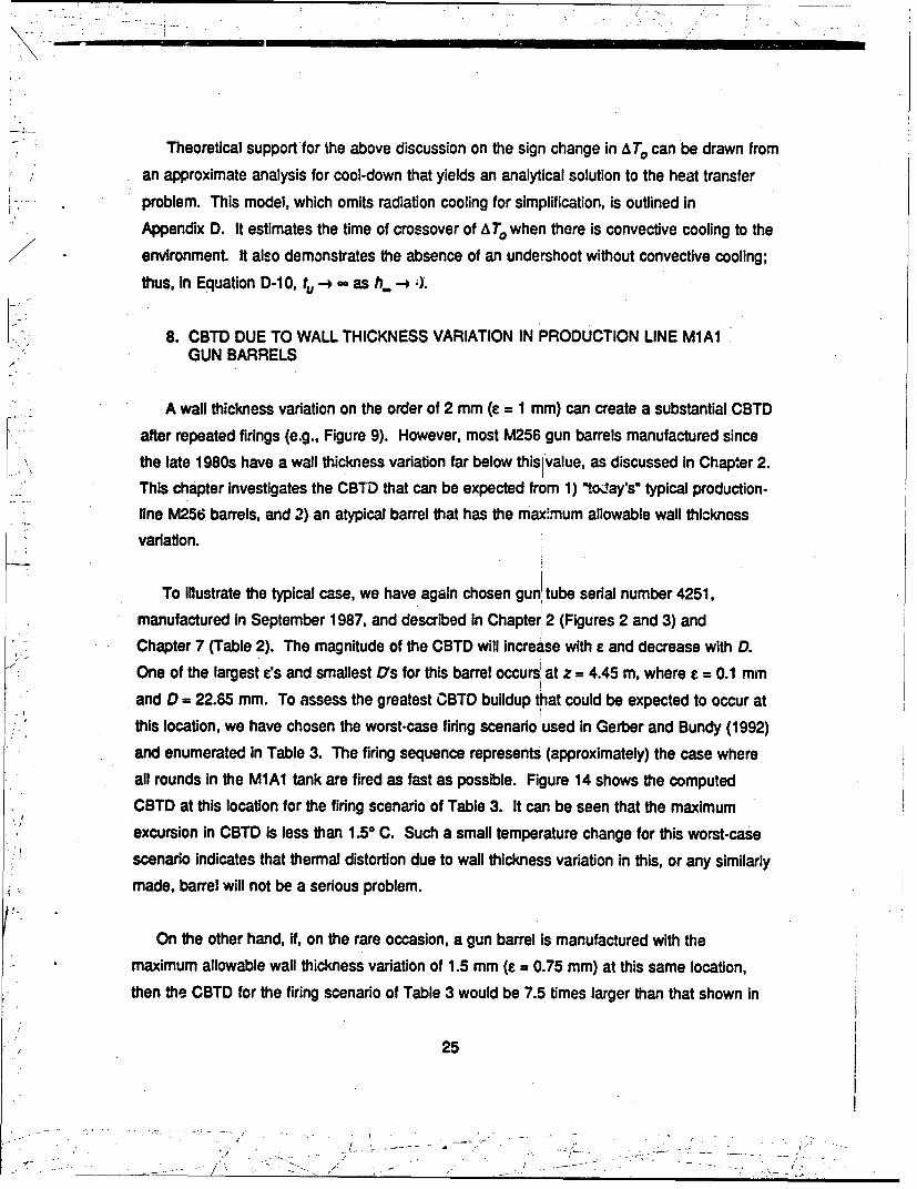
manufactured in September 1987, and described in Chapter7 2 (Figures 2 and 3) and
Chapter 7 (Table 2). The magnitude of the CBTD will increase with e and decrease with D.
One of the largest s's and smallest D7s for this barrel occurs at z = 4.45 m, where e = 0.1 mm
and D = 22.65 mm. To assess the greatest CBTD buildup that could be expected to occur at
this location, we have chosen the worst-case firing scenario used in Gerber and Bundy (1992)
and enumerated In Table 3. The firing sequence represents (approximately) the case where
all rounds in the M1A1 tank are fired as fast as possible. Figure 14 shows the computed
CBTD at this location for the firing scenario of Table 3. It can be seen that the maximum
excursion in CBTD is less than 1.50 C. Such a small temperature change for this worst-case
scenario indicates that thermal distortion due to wall thickness variation in this, or any similarly
made, barrel will not be a serious problem.
On the other hand, If, on the rare occasion, a gun barrel is manufactured with the
maximum allowable wall thickness variation of 1.5 mm (E = 0.75 mm) at this same location,
then the CBTD for the firing scenario of Table 3 would be 7.5 times larger than that shown in
25
- -..
Table 3. Worst Case Firing Scenario
1. 17 rounds at 7 rounds/min2. 5 minute cool-dowi3. 17 rounds at 7 rounds/min4. 5 minute cool-down5. 7 rounds at 7 rounds/min6. Cool-down
z =4.45 m
Tinf =295K, r=0.10mmD 22.65 mm
I-T
-0.5 t t i0 500 1000 1500 - 2000
t[s]
Figure 14. Worst case CBTD for M256 gun barrel, serial number 4251 (typical productionline barrel).
Figure 14 (based on the fact that &T0,1 Is proportional to e [Equation 17]). In this case, the
CBTD would be greater than 100 C, and according to our earlier discussion, the change In
muzzle pointing angle would probably exceed 0.5 mrad, noticeably degrading gun accuracy.
26
,. . .--- L ,
I,
In summary, the CBTD that arises during firing due to wall thickness variation is expected
to be relatively small for most gun barrels manufactured today. However, the current
tolerances would allow a gun barrel to be put into service that couid develop a large CBTD
during firing and hence, perform poorly from a thermal distortion/' 'n accuracy standpoint
Thus, consideration should be given to lowering the acceptable Y Al l thickness variation to the
same level that most barrels now have, viz., e ! 0.25 mm outside the chamber.
t2
' :-7
iA
INTENTIONALLY LEFT BLANK.
28
-. I' - .-. •- - --; . ; ,
9. REFERENCES
Bundy, M. L. "Thermal Distortion Protection by Candidate MetOl and Composite ThermalShrouds for 120-mm Tank Cannon." BRL-TR-2807, U.S. Army Ballistic ResearchLaboratory, Aberdeen Proving Ground, MD, June 1987a.
Bundy, M. L. "Analysis of Thermally Induced Barrel Distortion From Firing." Proceedings ofthe Fifth U.S. Army Symposium on Gun Dynamics, ARCCB-SP-87023, U.S. ArmyResearch, Development and Engineering Center, Close Combat Armament Center, BenetLaboratories, Watervliet, NY, September 1987b.
Chandra, S., and E. B. Fisher. "Simulation of Barrel Heat Transfer." DAAA15-88-D-0014,U.S. Army Ballistic Research Laboratory, Aberdeen Proving Ground, MD. June 1989a.
Chandra, S., and E. B. Fisher. "Analysis of 16-Inch/50 Gun Chamber Heating.* VeritayReport No. C68-1, Naval Ordnance Station, Indian Head, MD, October 1989b.
Gerber, N., and M. L Bundy. "Heating of a Tank Gun Barrel: Numerical Study.*BRL-MR-3932 (ADA241136), U.S. Army Ballistic Research Laboratory, AberdeenProving Ground, MD, August 1991.
Gerber, N., and M. L Bundy. "Effect of Variable Thermal Properties on Gun Tube Heating."BRL-MR-3984 (ADA253066), U.S. Army Ballistic Research Laboratory, AberdeenProving Ground, MD, July 1992.
Gough, P. S. "The NOVA Code: A User's Manual - Volume I. Description and Use."
IHCR-80-8, Naval Ordnance Station, Indian Head, MD, December 1980.
Holman, J. P. Heat Transfer. 5th ed., New York: McGraw-Hill Co., p. 6, 1981.
Manaker, A. M., and P. J. Croteau. "Study of Anti-Distortion Jackets." WVT-TR-76028,U.S. Army Benet Weapons Laboratory, Watervliet, NY, July 1976.
McDermott, J. "120-mm M256 Tube, Finished Machined, Dwg. No. 12528311." Sheet 1,rev. W, Procurement and Contracting D~rectorate, Watervliet Arsenal, NY, June 1991.
Overocker, B. Private communication. Production Planning and Control Division, WaterviietArsenal, NY, September 1991.
Ozisik, M. N. Boundary Value Problems in Heat Conduction. New York: Dover Publications,Inc., 1968.
Stratford, B. S., and G. S. Beavers. "The Calculation of the Compressible Turbulent BoundaryLayer in Arbitrary Pressure Gradient - A Correlation of Certain Previous Methods."No. 3207, Aeronautical Research Council R&M, 1961.
Talley, J. 0. "Barrel Heating and Chrome Plate Adhesion in the 120-mm M256 Gun Tube."
DAAA21-85-C-0389, U.S. Army Armament Research, Developmient, and EngineeringCenter, Picatinny Arsenal, NJ, September 1989.
29
_ _ _/ - .',/"

INTENTIONALLY LEFT BLANK.
30
APPENDIX A:
STATEMENT'OF PROBLEMS IN 4, t VARIABLES
31
//

N'. /
//
'I
I,,
INTENTiONALLY LEFT BLANK.
V.
32
///
- . - ,.,
"1I '1 II1 I -I * ,"
We repeat the transformation of Equation 14:
I;f)¥+11-¥1~ (0<y¥ 1,P > 2) r D ,Ri. (A-1)
Then
dtdt m u .+ p(1 -,)P'I d2 tId%2 ; . p(p-l) (I -_y)4p02
/ * ,"' (1) - pP-1)(i -''). (A-2)
We define f(e,) and f2(4):
If
f2 " (DI/,)/(D. Ri) - ýI/(,I)3. (A-3)
/ The transformed problem for T1 Is
'2/ ;T 1Itu (/O 2 [fl(t) 82 T1 /a42 + f2(t) aT1/,°] " Glg,t) , (A-4a)
Sk aTIIMZ -D hg y T1 , -Dhg y T , ,t>O , (A-4b)
[k1l(DX1)IaT/ +I [ + h..+ 4Fla(T13 ]T1 - h. T. + F[T.4 + 3 (Tlm)4]
S, -1, t > 0. (A-4c)
33
. / - /. •..
The transformed problem for T3 is
aT3 /at (/D 3/2)[fa 42T31F 2 + f2 aT3 /•4] - (czlr 2 )T3 , (A-5a)
[k/(Dy)] aT31I4 - hg T3 ,0 , 0, t> 0, (A-5b)
[1/1(D,.)] aT 3 1aI + (h..4FoTeI )T3 1k - W(T 1 )
.1, t > o , (A-5c)
where r is given in Equation A-i, X. is given In Equation A-2. T0 and hg are known functions
of L V4T 1) is defined in Equation 12 and is evaluated in Equation B-1 le.
The Initial conditions are
T7"-".. t-O, 0< 5S
T3 -0 t -0 , 0 <:5 1. (A-6)
34
APPENDIX B:
COEFFICIENTS IN EQUATIONS 20 AND 21
35
INTENTIONALLY LEFT BLANK.
36
The following functions of • are defined in Equations A-1, A-2, and A-3: r, s , ,, f2"
Also defined are y= - ý(0), XI'= •,M(1), X m •(1). The equations are solved for t= tm*';
tm denotes the preceding time step, when all quantities are known.
Three additional functions of P are as follows:
91 (aID 2 ) [fl/(-)2 - f2/(2 g)1,
g2 " -(2 a/D 2 ) fl/(,g)2,
g3 - (a/D 2)[fI/(txg) 2 + f2/(2 Q].)] (B-i)
The coefficients Aj. and dj in Equation 20 are now given:
.'.. All - 3 + 2,&t Dy¥hg/k, A12 .-- 4, A13-s 1,(B2
" ANN.1.. 1I , ANI.INI- -4
,,•"ANI.INI+1 -3 + (2A,t D X,1k) [h. + 4 Fa(T T1N 3) at r-Ro. (B-3)
For 2: ;j< NI,
- ~~~Aj.j-.1 ,-(A tl2) g, (4~j). ~ j1
A * 1 - (W/12) g2(~) Aij,1 (W/12) g3(4j) (B-4)
37
I 37-I.. .. -.. . . ..-., _ -,' . . I-'•, . - . -.- , * • , , ."_________," It " -• " -,• , ,, , • r' • - F,". .• -.
All other coefficients Aj. are equal to zero.
dl .2 A Dy hgTg/k,
d 2 4D~ 1)[h Tý+ d + 3 NI, M1,
For 2 :j!5 NI,
dj .m + (At/2) Gm (B-6a)
where
Gi gr-, T, g÷(j T m+g3(j)T (-bJ-1 lJ+I(B6
Now the coefficients Bjn and ej in Equation 21 are given:
BI1 - All, B12 u A12 , B13 - A 13 , (B-7)
BNI,,1N,-I 1. BNI.INI - -4,
BN,÷,,N÷,, 3 + (2 A• DX.l/k) [h.+4Fd(Tml+I 3]. (3-8)" NI÷ I(B8
For 2 s j< NI,
B,1 Aj,. 1 , B,, u As, + (cx A t/2 )/r2, Bjj, 1 - Aj,j, 1 . (B-9)
All other coefficients Bin are equal to zero.
e1 = O, eNl+ 1 -2D 1X, W( Tm* (B-10)1N/1
38
-,7" J - /.. •- . . ... -7 -. • •y . - : " ,. . , , • . r ,- : • .. "..
-.. _..--
where WI(Tit"*' defined In Equation 12, is approximated by the following sequence,
evaluated at t t"' 1 , where rand , subscripts denote partial differentiatio;n:
kTitl-1) -h. T. + Foa[T.4 31T1 m.)4
[h) a m 3 ],M+ (B-1 1a)-[h- 4F°I1+1÷ 1N1.1 I
,Ti(-1 ). DM, T, I(1), (B-1 Ib)
T 1,(1).[11{2(,,)2}][8T1NT,.-7TN]+(3/at) Tl (1) ()(B-11C)
" Ttr11- 1/I211ff 1 Tl,, 440) (%12/14) T1, (1)]1 (B-1 1d)
'.W(T1NI -A -Tlrr(1) - [h. 4 4Fa1 T,1* m 3] T) 1 1kNI f 1H1 T(1)lk" (-1e)
For 2 j:5 NI,
Ti j
where -M )T•1 13,M + .t 2 (1-)T213 lg3r 1) (B-13)
j 3j3 1- 3
) 39-1 1 •
39

INTENTIONALLY LEFT BLANK.
40
APPENDIX C:
TIME SCALE
41
//
INTENTIONALLY LEFT BLANK.
42
X • " -" ... 1/
I',/:
i ,,
//
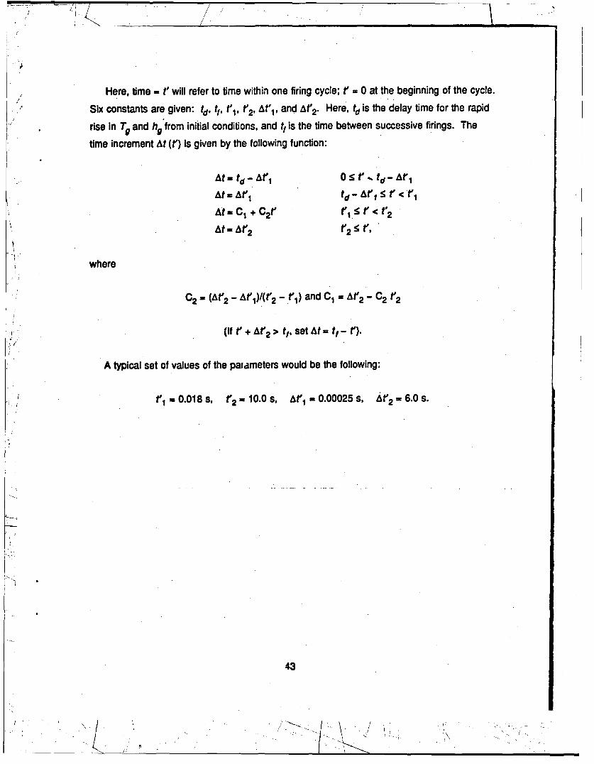
Here, time =t' will refer to time within one firing cycle; rt 0 at the beginning of the cycle.
Six constants are given: td, tIf t'. t'2, At'1, and At2. Here, td is the delay time for the rapid
rise In Tg and hg from initial conditions, and tt is the time between successive firings. The
time Increment At (t) is given by the following function:
SA t - td -A t " 0 S; r " . td - A t "1
At = At'1 td - At" S t" < t"
At = C1 + C2t' (1 < r < t2
At = At'2 t2 !5 t
where
C2 - (At'2 - At'l)/(t' 2 - t',) and C1 = At' 2 - C2 t'2
2.- (If tr + At'2 > tf, set At= t1- t').
A typical set of values of the parameters would be the following:
t', 0.018 s, t 2̀ , 10.0 s, At' 1 - 0.00025 s, At'2 - 6.0 S.
43
-2.._
INTENTIONALLY LEFT BLANK.
44
APPENDIX 0:
ANALYTICAL MODEL OF COOLING
45
INTENTIONALLY LEFT BLANK.
46
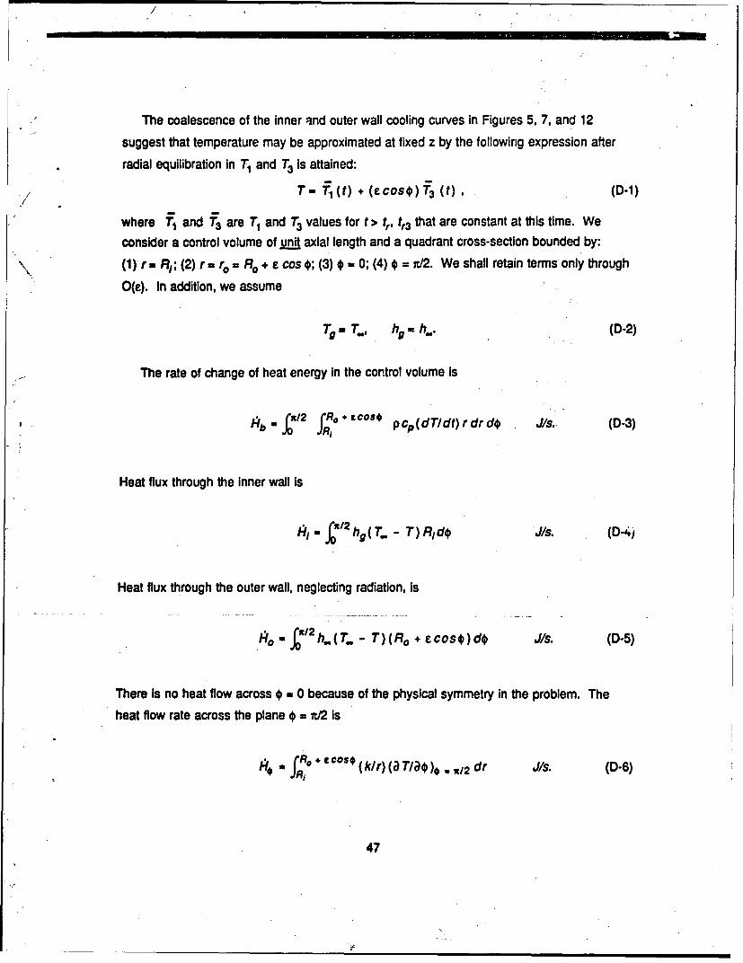
The coalescence of the inner and outer wall cooling curves in Figures 5, 7, and 12
suggest that temperature may be approximated at fixed z by the following expression after
radial equilibration in T1 and T3 is attained:
T - T- (t) + (CCos) T3 (t), (D-1)./
where f 1 and f 3 are T1 and T3 values for t > tr, tr3 that are constant at this time. We
consider a control volume of unit axial length and a quadrant cross-section bounded by:
(1) r- RI; (2) r= re = Ro + e cos*; (3)* = 0; (4) = i./2. We shall retain terms only through
O(e). In addition, we assume
Tg -T., hg h.. (D-2)
The rate of change of heat energy in the control volume is
Hbin (z12 (R 0 .os'°* pcp(dTIdt)rdrd Js. (-3)
fR1
Heat flux through the Inner wall is
" h(". - T) Rido J/s. (D-4)
Heat flux through the outer wall, neglecting radiation, is
h40 /X2 h..(T. - T)(Ro + ecos$)d$ J/s. (D-5)
There Is no heat flow across # 0 because of the physical symmetry in the problem. The
heat flow rate across the plane* = n/2 is
1 fR.° "" €ost (klr) (a TIao), . z/2 dr J/s. (D-6)
47
The energy balance equation is
Hb -141 0 ;4/ 0 +4/. (D-7)
Equation D-1 is substituted into Equations D-3, D-4, D-5, and D-6. When these equations
are substituted into Equation D-7, and coefficients of like powers of e are collected, we obtainlinear first-order ordinary differential equations for T1 and T3 . The solution Is
"T, T.. + [T1 (ta) - T..] exp[-cl(t - ta)]. (D-8a)
S- c2 exp[-c1 (t - ta)] + [T3 (ta) - c2 ] exp[-c 3 (t - ta)] , (D-8b)
where
cl - 2h./[pcpl(R - R1)] , (D-9a)
c 2 - (h./k) (Ro + RI)[Ti (ta) - T.]/[(Ro - R,) in(RoIRi)] , (D-9b)
c3 - cl + [2 k In (Ro/Ri)]/[pcp(Ro -/R/)] . (D-9c)
The quantities T1 (tQ) and T3 (tQ) are finite-difference results for r = Ro at a time t= tg (> tr,
t.3), chosen so that T3 (ta) < 0 (or AT, > 0). The time of undershoot, tu., is found by setting
f3 in Equation D-8b equal to zero:
t ta+ [pcp(R2 - R) /(2 k/In (Ro/R,)}]
x T3(t)k (Ro - RI) In(RoIRi) 1 (D-10)
h.. (Ro + Rj)lTi(ta) - T.) I
48
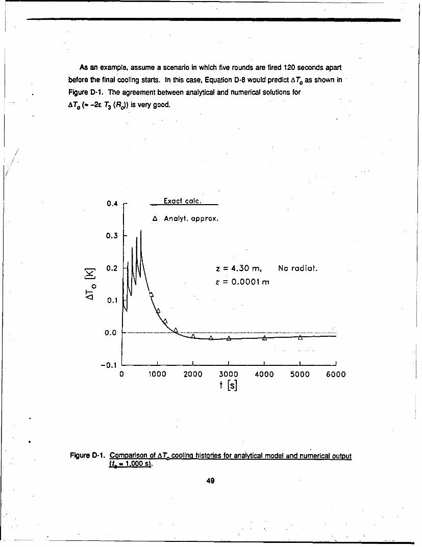
As an example, assume a scenario in which five rounds are fired 120 seconds apart
before the final cooling starts. In this case, Equation D-8 would predict AT, as shown in
Figure D-1. The agreement between analytical and numerical solutions for
ATO (- -2e T3 (Rd) is very good.
0.4 Exact caic.
Ai Anolyt. approx.
0.3
0.2 z =4.30 m, No radiot.
0 C=0.0001 M
0.1
-0.1 I
0 1000 2000 3000 4000 5000 6000t [s]
Figure D-1. Comparison of A.T cooling histories for analytical model and numerical outputUt ,00 1.OS1.
49

INTENTIONALLY LEFT BLANK.
50
*" I I "' ' " ' \ . . '
LIST OF SYMBOLS
Aim B, coefficients in linear equations for T1 and T3 , Equations 20 and 21
C, specific heat of gun barrel (Joules/kg K]) .
c 1, c 2 , c3 constants defined in Equations D-9
CBTD cross-barrel temperature difference
dt ej coefficients In linear equations for T1 and T3, right-hand sides ofEquations 20 and 21
D *Ro-Ri [m, mm]
"fl,12 given functions of F, Equation A-3
F radiation interchange factor, Equation 6
Oi1 ,2, 93 functions of 4, defined in Equation B-1
G (4,0) function of 4 and t, defineq in Equations A-4a and B-6
(4, t) function of 4 and t, defined in Equation B-13
hg (t, z) heat transfer coefficient - pore gas to gun barrel (Joules/{m2 s K))
h. (z) heat !'ansfer coefficient - un barrel to ambient air (Joules/{m2 s K))
j subscript Index Indicating adial location of a nodal point
k thermal conductivity of gu barrel (Joules/(m s K))
m superscript index Indicating time value
n arc length along line normal to the surface of the outer wall
N/ number of intervals in R1 :5 r5 R. formed by the nodal points
r radial coordinate in transverse plane [im, mm] (r = 0 at axis of gun bore)
r* radial coordinate in transverse plane (r' = 0 at axis of outer wall)
ro .- r,(O) - radial coordinate of outer wall - Re + C cos,
Ri radius of circular inner wall [m, mm]
51
ji Q i.,o , ,, _ _ _ __I I_ _
/•
RO radius of circular outer wall [m, mm]
t time from initiation of first round [s, ms, min]
ta initial time for analytical model, Equations D-8 [s]
td delay time at given z for rapid rise In T9 and hg [s, mis]
't time interval between successive rounds
tr rise time for T1 [s, ms]
tr3 rise time for T3 [s, ms]
tu time at which AT. changes sign, Equation D-10 Is]
time measured within a firing cycle [s, ms]
t1 ', t2' two prescribed time values in Timescale formula, Appendix C Is]
T temperature In the gun barrel [K]
T9 Tdt) - temperature in the bore at a fixed z-value [K]
T r, TO temperatures at irner and outer walls, respectively, of gun barrel [K],Equations 15 and 16
T, axisymmetric contribution to barrel temperature, Equation 9 [K]
T3 function furnishing non-axisymmetric contribution to barrel temperature,Equation 9 [K/m]
T1' T3 analytical approximation to T, and T3 , respectively, Equation D-1
T.,, Tinf temperature in ambient air [K]
U. unit vector normal to the outer wall
IVT 1) function of T1 defined in Equation 12, evaluated in Appendix B
z axial coordinate (z a 0 at breech) [im]
o. a k/(p cd) = thermal diffusivity of gun barrel [m2/s]
p3, y prescribed constants in transformation formula, Equation 14
At time increment for calculation of temperature profile, Equation 19 [s]
52
"T
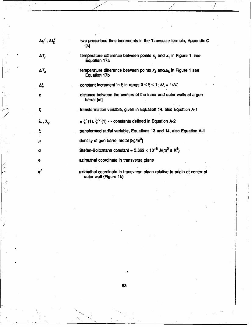
At11 , At2/ two prescribed time increments In the Timescale formula, Appendix C
Is]
A Tr temperature difference between points x2 and x1 in Figure 1, ceeEquation 17a
A To temperature difference batween points x4 anc.* In Figure 1 see
Equation 17b
constant Increment in i in range 0 < 4:5 1; g = I/NI
e distance between the centers of the Inner and outer walls of a gunbarrel [m]
C transformation variable, given in Equation 14, also Equation A-1
', ½ - •' (1), t" (1) - - constants defined In Equation A-2
transformed radial variable, Equations 13 and 14, also Equation A-1
p density of gun barrel metal [kg/mrJ
o Stefan-Boltzmann constant = 5.669 x 10⁻⁸ J/(m2 s K4)
* azimuthal coordinate In transverse plane
azimuthal coordinate in transverse plane relative to origin at center ofouter wall (Figure 1b)
.5
53
INTENTIONALLY LEFT BLANK.
54
No. of No. ofCopies Oranization Copies Organization
2 Administrator 1 CommanderDefense Technical Info Center U.S. Army Missile CommandATTN: DTIC-DDA ATTN: AMSMI-RD-CS-R (DOC)Cameron Station Redstone Arsenal, AL 35898-5010Alexanoraa, VA 22304-6145
1 CommanderSCommander U.S. Army Tank-Automotive Command
U.S. Army Materiel Command ATTN: ASQNC-TAC-DIT (TechnicalATTN: AMCAM Information Center)5001 Eisenhower Ave. Warren, MI 48397-5000Alexandria, VA 22333-0001
I DirectorI Director U.S. Army TRADOC Analysis Command
U.S. Army Research Laboratory ATTN: ATRC-WSRATTN: AMSRL-D White Sands Missile Range, NM 88002-55022800 Powder Mill Rd.Adelphi, MD 20783-1145 1 Commandant
U.S. Army Field Artillery SchoolDirector ATTN: ATSF-CSIU.S. Army Research Laboratory Ft. Sill, OK 73503-5000ATTN: AMSRL-OP-CI-AD,
Tech Publishing (cIS. U=y)1 Commandant2800 Powder Mill Rd. U.S. Army Infantry SchoolAdelphi, MD 20783-1145 ATTN: ATSH-CD (Security Mgr.)
Fort Benning, GA 31905-56602 Commander
U.S. Army Armament Research, (runam. a ~y)1 , C mandantDevelopment, and Engineering Center U Army Infantry School
ATTN: SMCAR-IMI-l Al 1: ATSH-CD-CSO-ORPicatinny Arsenal, NJ 07806-5000 Fort Benning, GA 31905-5660
2 Commander 1 WLIMNOIU.S. Army Armament Research, Eglin AFB, FL 32542-5000
Development, and Engineering CenterATTN: SMCAR-TDC Aberdeen Proving GroundPicatinny Arsenal, NJ 07806-5000
2 Dir, USAMSAASDirector ATrN: AMXSY-D
Benet Weapons Laboratory AMXSY-MP, H. CohenU.S. Army Armament Research,
Development, and Engineering Center I Cdr, USATECOMATTN: SMCAR-CCB-TL ATTN: AMSTE.TCWatervliet, NY 12189-4050
1 Dir, ERDEC(Uncta. -n)l Commander ATTN: SCBRD-RT
U.S. Army Rock Island ArsenalATTN: SMCRi-IMC-RT/Technical Library 1 Cdr, CBDARock Island, IL 61299-5000 ATTN: AMSCB-CI
Director 1 Dir, USARLU.S. Army Aviation Research ATTN: AMSRL-SL-I
and Technology ActivityATTN: SAVRT-R (Library) 10 Dir, USARLM/S 219-3 ATTN: AMSRL-OP-C B (Tech Lib)Ames Research CenterMoffett Field, CA 94035-1000
55
No. of No. ofCopies Organization C Organization
16 Director 2 CommanderBenet Weapons Laboratory U.S. Army Armament Research,U.S. Army Armament Research, Development, and Engineerirn3 Center
Development, and Engineering Center ATTN: SMCAR-CCH,ATTN: SMCAR-CCB-DS, R. Hasenbein E. Del Coco
SMCAR-CCB-DA, K. PflegerJ. Neice Picatinny Arsenal, NJ 07806-5000G. Carafarp
SMCAR-CCB-RA, 2 CommanderB. Pflegl U.S. Army Armament Research,P. O'Hara Development, and Engineering Center
SMCAR-CCB-RT, ATTN: C. LangonB. Avitzar J. DelabarS. Sopok Picatinny Arsenal, NJ 07806-5000
SMCAR-CCB-PM, M. WithesellSMCAR-CCB-DI, C. Rinaldi 1 DirectnrSMCAR-CCB-RP, Weapons Department
J. Cox U.S. Army Armor SchoolG. Capsinalis ATTN: ATSB-WP-ORSA, A. Pomey
SMCAR-CCB-DS, P. Votlis Fort Knox, KY 40121-5212SMCAR-CCB-DS, C. AndradeSMCAR-LBD-D, J. Zweig 1 Paul Gough Associates, Inc.SMCAR-CCB, L. Johnson ATTN: Dr. Paul S. GoughSMCAR-CCB-DA, L. Bennett '048 South St.
Watervliet, NY 12189-4050 Portsmouth, NH 03801-5423
2 Dircctor 2 Iferitay Technology IncorporatedBenet Weapons Laboratory ATTN: E. B. FisherU.S. Army Armament Research, J. Z. Talley
Development, and Engineering Center P.O. Box 305ATTN: T. Allen 4845 Millersport Highway
B. Artus East Amhurst, NY 14051Watervliet, NY 12189-4050
CommanderU.S. Army Tank-Automotive CommandATTN: SFAE-ASM-AB-SW, Dr. PattisonWarren, MI 48397-5000
5 CommanderTank Main Armament SystemATTN: SFAE-AR-TMA,
K. RussellE. KopaczK. RubenF. HildebrandS. Bqlinstein
Picatinny Arsenal, NJ 07806-5000
56
SK
USER EVALUATION SHEET/CHANGE OF ADDRESS
This Laborato.y undertakes a continuing effort to improve the quality of the reports it publishes. Yourcomments/answers to the itcens/questions below will aid us in our efforts.
1. ARL Report Number hL,-TR-100 Date of Report March 1993
2. Date Report Received
3. Does this r.,tn satisfy a need? (Comment on purpose, related project, or other area of interest for
which the report will be used.)
4. Specifically, how is the report being used? (Information source, design data, procedure, source of
ideas, etc.)
5. Has the information in this report led to any quantitative savings as far as man-hours or dollars saved,
operating costs avoided, or efficiencies achieved, etc? If so, please elaborate.
6. General Comments. What do you think should be changed to improve future reports? (Indicatechanges to organization, technical content, format, etc.)
Organization
CURRENT NameADDRESS
Street or P.O. Box No.
"City, State, Zip Code
7. If indicating a Change of Address or Address Correction, please provide the Current or Correct addressabove and the Old or Incorrect address below.
Organization
OLD NameADDRESS
Street or P.O. Box No.
City, State, Zip Code
(Remove this sheet, fold as indicated, staple or tape closed, and mail.)
-' / ,"I,.., . . .•.
DEPARTMENT OF THE ARMY. ~NO POST"AGE•
• I ~NE=CESSAR Y
i IF IWAILIO
! ,, IN THE .
OFRCIAL BUSINESS REPLY III -SS
/ FRST C3.S FEWoS No 0001, APS, MO
Postage will be Paid by addressee
Director -U.S. Army Research LaboratoryATTN: AMSRL-OP-CI-B (Tech Lib)Aberdeen Provinp Ground, MD 21005-5066
----------------- --- ----------------------.-.------ ----
Z/74w?
DTIC


![M1 Garand Barrel Replacement – New Barrel[1]](https://static.fdocuments.net/doc/165x107/577c79801a28abe05492e684/m1-garand-barrel-replacement-a-new-barrel1.jpg)