
CROMPTON INSTRUMENTS ANALOGUE METERS FOR MARINE · PDF fileenergy ///...
24
ENERGY /// CROMPTON-INSTRUMENTS.COM/ANALOGUE.HTML CROMPTON INSTRUMENTS ANALOGUE METERS FOR MARINE APPLICATIONS
Transcript of CROMPTON INSTRUMENTS ANALOGUE METERS FOR MARINE · PDF fileenergy ///...
ENERGY /// CROMPTON-INSTRUMENTS.COM/ANALOGUE.HTML
CROMPTON INSTRUMENTSANALOGUE METERS FOR MARINE APPLICATIONS

ENERGY /// CROMPTON-INSTRUMENTS.COM/ANALOGUE.HTML
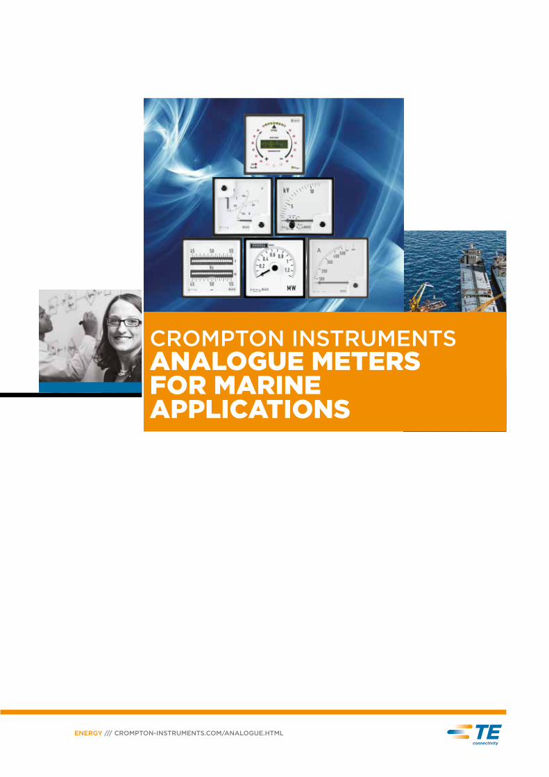
High quality analogue instruments designed to measure a wide range of electrical parameters.
This comprehensive range offers quadratic instruments in different dimensions. Products
are available as voltmeters, ammeters, voltmeters and ammeters incorporating a selector
switch, power meters, energy meters incorporating a power indicator, process indicators and
synchroscopes. To suit the needs of the shipbuilding and associated industries, manufacturing
equipment for sea-going vessels, these instruments are CE marked and approved by Bureau
Veritas (BV) under certification numbers 38933/A0 BV, 38940/A0 BV, 38941/A0 BV, 38942/A0 BV.
ANALOGUE INSTRUMENTS FOR MARINE APPLICATIONS
Features• Extensive range
• Accurate measurement and display of electrical parameters
• Up to four different case sizes
• Wide range of specifications
• Designed for reliable operation in marine and offshore environments
Benefits• Cost effective
• Local indication
• Easy installation
• Minimal operator training
• Low maintenance level
Applications• Switchgear
• Distribution systems
• Control panels
• Process control
• Motor control
Approval• Bureau Veritas
Standards• CE marked
• BV approved
PAGE 1
Moving Iron Ammeters and Voltmeters ............................................................................................................ 2Moving iron AC voltmeters – available in four case sizes. Versions to reflect typical voltage transducer ratios in marine
applications complete the range. Moving iron AC ammeters for direct AC currents or CT connections. Available in four
case sizes with different inputs and scalings for no overload and 2 x or 6 x overload.
AC Ammeters and Voltmeters Rectified .......................................................................................................... 3Rectified moving coil meters with shielded movement for linear AC measurement. Available in three case sizes for a
wide range of inputs.
DC Ammeters and Voltmeters .......................................................................................................................... 4-5Used for direct measurement of DC signals. Available in four case sizes. Variations allow transducer and shunt
indicators. Live zero, offset zero and centre zero measurement.
AC Ammeters and Voltmeter with Selector Switch ..................................................................................... 6Integrated selector switch reduces installation time and links the meter clearly to the switch. Ammeter is CT connected.
Voltmeters are either direct or VT connected.
Frequency Meters with Pointer or Reeds ......................................................................................................... 7Pointer indicator and reed indicator versions available for a variation of frequency ranges and different voltage levels.
Phase Sequence Indicator ...................................................................................................................................... 8Phase sequence indicators are used to determine the correct phase sequence in three phase networks. Supplied with
two built in glow bulbs indicating correct / incorrect sequence.
Dual Voltmeter and Frequency Meter ............................................................................................................... 9Used for direct comparison of two electrical systems (bus and generator). Supports to determine the preconditions
prior to parallel operation. Frequency meters available as pointer or reed versions.
Power Factor Meters .............................................................................................................................................. 10Power factor meters determine if systems are running with inductive or capacitive load. Variation of system
connections available. Including “through hole” CT connection.
Wattmeters and Varmeters .............................................................................................................................. 11-13Panel mounted energy meters combine a Watt or Varmeter with a counter for Watthours of Varhours. Available for
different electrical systems and voltage levels. Relay output built in as standard
Energy Meter with Power Indicator ............................................................................................................. 14-16Panel mounted energy meters combine a Watt or Varmeter with a counter for Watthours of Varhours. Available for
different electrical systems and voltage levels. Relay output built in as standard.
Synchroscope ....................................................................................................................................................... 17-18Synchroscopes are used to prevent an asynchronous connection of bus and generator. Available as 360° LED
indicators with different functionality. Version with additional LCD display available to show electrical values.
Technical Details ....................................................................................................................................................... 19
Standards and Approvals....................................................................................................................................... 19
CONTENTS
ENERGY /// CROMPTON-INSTRUMENTS.COM/ANALOGUE.HTML
Bezel size (mm) 48 72 96 144
Scale length (mm) 41 62 92 135
AC ammeter M242-02A-S M243-02A-S M244-02A-S M246-02A-S
X2 AC ammeter M242-022A-S M243-022A-S M244-022A-S M246-022A-S
X6 AC ammeter M242-026A-S M243-026A-S M244-026A-S M246-026A-S
AC voltmeter M242-02V-S M243-02V-S M244-02V-S M246-02V-S
Standard input ranges
AC ammeter (0/x A)1, 2, 2.5, 4, 5, 6, 10, 15, 20, 25, 30, 40, 60 A (M242 limited to 25A)
X2 AC ammeter (0/x A)1/2, 2/4, 2,5/5, 4/8, 5/10, 60/12, 10/20, 15/30, 20/40, 30/60, 40/80, 60/120 A (M242 limited to 25/50A)
X6 AC ammeter (0/x A)1/6, 2/12, 2,5/15, 4/24, 5/30, 6/36, 10/60, 15/90, 20/120, 25/150, 30/180, 40/240, 50/300, 60/360 A (M242 limited to 25/150 A)
AC voltmeter (0/x V) 250V, 300V, 500V, 600V
AC voltmeter for VT connection (0/x V)
120V (for use with VT`s x/100V), 132V (for use with VT`s x/110V), 144V (for use with VT`s 120V), 125V, 137,5V, 150V (for use with some VT`s having primary voltage less then 1kV)
Connection DiagramsAC Ammeter AC Voltmeter
Product Codes
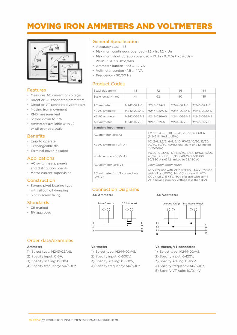
MOVING IRON AMMETERS AND VOLTMETERS
Features• Measures AC current or voltage
• Direct or CT connected ammeters
• Direct or VT connected voltmeters
• Moving iron movement
• RMS measurement
• Scaled down to 15%
• Ammeters available with x2
or x6 overload scale
Benefits• Easy to operate
• Exchangeable dial
• Terminal cover included
Applications• AC switchgears, panels
and distribution boards
• Motor current supervision
Construction• Sprung pivot bearing type
with silicon oil damping
• Slot in screw fixing
Standards• CE marked
• BV approved
General Specification• Accuracy class - 1.5
• Maximum continuous overload - 1.2 x In, 1.2 x Un
• Maximum short duration overload - 10xIn - 9x0.5s+1x5s/60s -
2xUn - 9x0.5s+1x5s/60s
• Ammeter burden - 0.3 … 1.2 VA
• Voltmeter burden - 1.5 … 4 VA
• Frequency - 50/60 Hz
Order data/examples
Ammeter
1) Select type: M243-02A-S,
2) Specify input: 0-5A,
3) Specify scaling: 0-100A,
4) Specify frequency: 50/60Hz
Voltmeter
1) Select type: M244-02V-S,
2) Specify input: 0-500V,
3) Specify scaling: 0-500V,
4) Specify frequency: 50/60Hz
Voltmeter, VT connected
1) Select type: M244-02V-S,
2) Specify input: 0-120V,
3) Specify scaling: 0-12kV,
4) Specify frequency: 50/60Hz,
5) Specify VT ratio: 10/0.1 kV
PAGE 3
Connection DiagramsAC Ammeter AC Voltmeter
Bezel size (mm) 48 72 96 144
Scale length (mm) 41 62 92 135
AC ammeter rectified 90°
M242-01B-S M243-01B-S M244-01B-S M246-01B-S
AC voltmeter rectified 90°
M242-01W-S M243-01W-S M244-01W-S M246-01W-S
Bezel size (mm) 48 72 96 144
Scale length (mm) 71 113 155 235
AC ammeter rectified 240°
M242-05B-S M243-05B-S M244-05B-S M246-05B-S
AC voltmeter rectified 240°
M242-05W-S M243-05W-S M244-05W-S M246-05W-S
Standard input ranges
AC ammeter rectified 90° and 240° scaling (0/x A) meter (0/x A)
1, 5 A (M242-05B-S delivered with separated current transformer)
AC voltmeter rectified 90° and 240° scaling (0/x V)
20, 15, 20, 30, 60, 100, 150, 250, 300 (limit at M242). 400, 500, 600 V
AC voltmeter for VT connection (0/x V)
120V (for use with VT`s x/100V), 132V (for use with VT`s x/110V), 144V (for use with VT`s 120V), 125V, 137,5V, 150V (for use with some VT`s having primary voltage less then 1kV)
Product Codes
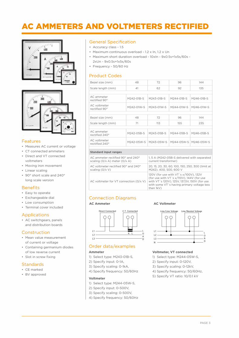
Features• Measures AC current or voltage
• CT connected ammeters
• Direct and VT connected
voltmeters
• Moving iron movement
• Linear scaling
• 90° short scale and 240°
long scale version
Benefits• Easy to operate
• Exchangeable dial
• Low consumption
• Terminal cover included
Applications• AC switchgears, panels
and distribution boards
Construction• Mean value measurement
of current or voltage
• Containing germanium diodes
of low reverse current
• Slot in screw fixing
Standards• CE marked
• BV approved
General Specification• Accuracy class - 1.5
• Maximum continuous overload - 1.2 x In, 1.2 x Un
• Maximum short duration overload - 10xIn - 9x0.5s+1x5s/60s -
2xUn - 9x0.5s+1x5s/60s
• Frequency - 50/60 Hz
Order data/examplesAmmeter
1) Select type: M243-01B-S,
2) Specify input: 0-1A,
3) Specify scaling: 0-1kA,
4) Specify frequency: 50/60Hz
Voltmeter
1) Select type: M244-05W-S,
2) Specify input: 0-500V,
3) Specify scaling: 0-500V,
4) Specify frequency: 50/60Hz
Voltmeter, VT connected
1) Select type: M244-05W-S,
2) Specify input: 0-120V,
3) Specify scaling: 0-12kV,
4) Specify frequency: 50/60Hz,
5) Specify VT ratio: 10/0.1 kV
AC AMMETERS AND VOLTMETERS RECTIFIED
ENERGY /// CROMPTON-INSTRUMENTS.COM/ANALOGUE.HTML
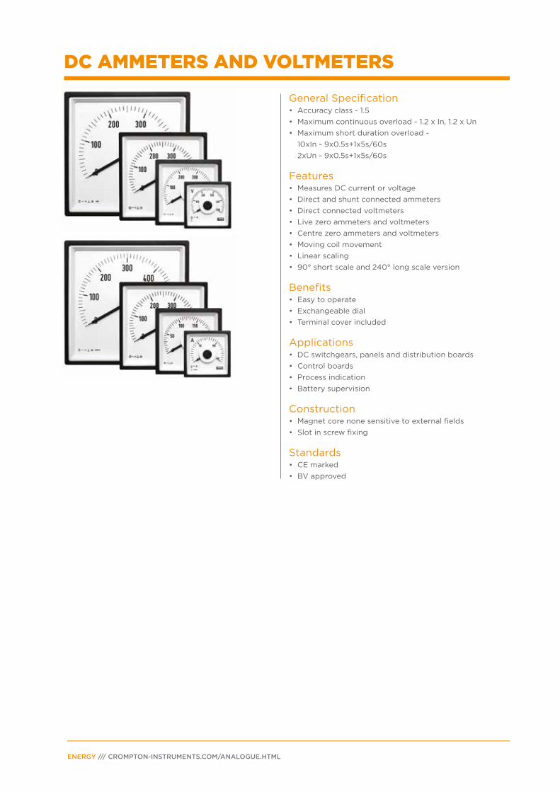
General Specification• Accuracy class - 1.5
• Maximum continuous overload - 1.2 x In, 1.2 x Un
• Maximum short duration overload -
10xIn - 9x0.5s+1x5s/60s
2xUn - 9x0.5s+1x5s/60s
Features• Measures DC current or voltage
• Direct and shunt connected ammeters
• Direct connected voltmeters
• Live zero ammeters and voltmeters
• Centre zero ammeters and voltmeters
• Moving coil movement
• Linear scaling
• 90° short scale and 240° long scale version
Benefits• Easy to operate
• Exchangeable dial
• Terminal cover included
Applications• DC switchgears, panels and distribution boards
• Control boards
• Process indication
• Battery supervision
Construction• Magnet core none sensitive to external fields
• Slot in screw fixing
Standards• CE marked
• BV approved
DC AMMETERS AND VOLTMETERS
PAGE 5
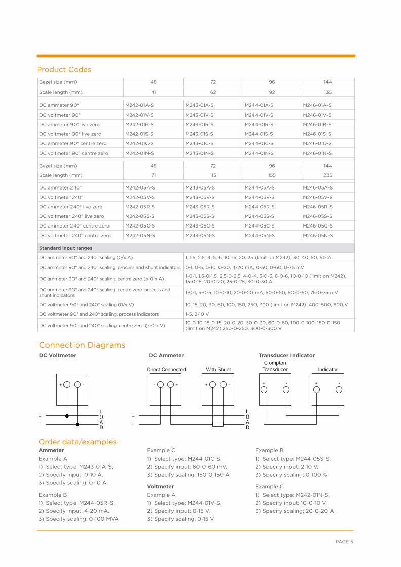
Product Codes
Connection DiagramsDC Voltmeter DC Ammeter Transducer Indicator
Bezel size (mm) 48 72 96 144
Scale length (mm) 41 62 92 135
DC ammeter 90° M242-01A-S M243-01A-S M244-01A-S M246-01A-S
DC voltmeter 90° M242-01V-S M243-01V-S M244-01V-S M246-01V-S
DC ammeter 90° live zero M242-01R-S M243-01R-S M244-01R-S M246-01R-S
DC voltmeter 90° live zero M242-01S-S M243-01S-S M244-01S-S M246-01S-S
DC ammeter 90° centre zero M242-01C-S M243-01C-S M244-01C-S M246-01C-S
DC voltmeter 90° centre zero M242-01N-S M243-01N-S M244-01N-S M246-01N-S
Bezel size (mm) 48 72 96 144
Scale length (mm) 71 113 155 235
DC ammeter 240° M242-05A-S M243-05A-S M244-05A-S M246-05A-S
DC voltmeter 240° M242-05V-S M243-05V-S M244-05V-S M246-05V-S
DC ammeter 240° live zero M242-05R-S M243-05R-S M244-05R-S M246-05R-S
DC voltmeter 240° live zero M242-05S-S M243-05S-S M244-05S-S M246-05S-S
DC ammeter 240° centre zero M242-05C-S M243-05C-S M244-05C-S M246-05C-S
DC voltmeter 240° centre zero M242-05N-S M243-05N-S M244-05N-S M246-05N-S
Standard input ranges
DC ammeter 90° and 240° scaling (0/x A) 1, 1.5, 2.5, 4, 5, 6, 10, 15, 20, 25 (limit on M242), 30, 40, 50, 60 A
DC ammeter 90° and 240° scaling, process and shunt indicators 0-1, 0-5, 0-10, 0-20, 4-20 mA, 0-50, 0-60, 0-75 mV
DC ammeter 90° and 240° scaling, centre zero (x-0-x A)1-0-1, 1.5-0-1.5, 2.5-0-2.5, 4-0-4, 5-0-5, 6-0-6, 10-0-10 (limit on M242), 15-0-15, 20-0-20, 25-0-25, 30-0-30 A
DC ammeter 90° and 240° scaling, centre zero process and shunt indicators
1-0-1, 5-0-5, 10-0-10, 20-0-20 mA, 50-0-50, 60-0-60, 75-0-75 mV
DC voltmeter 90° and 240° scaling (0/x V) 10, 15, 20, 30, 60, 100, 150, 250, 300 (limit on M242). 400, 500, 600 V
DC voltmeter 90° and 240° scaling, process indicators 1-5, 2-10 V
DC voltmeter 90° and 240° scaling, centre zero (x-0-x V)10-0-10, 15-0-15, 20-0-20, 30-0-30, 60-0-60, 100-0-100, 150-0-150 (limit on M242) 250-0-250, 300-0-300 V
Order data/examplesAmmeter
Example A
1) Select type: M243-01A-S,
2) Specify input: 0-10 A,
3) Specify scaling: 0-10 A
Example B
1) Select type: M244-05R-S,
2) Specify input: 4-20 mA,
3) Specify scaling: 0-100 MVA
Example C
1) Select type: M244-01C-S,
2) Specify input: 60-0-60 mV,
3) Specify scaling: 150-0-150 A
Voltmeter
Example A
1) Select type: M244-01V-S,
2) Specify input: 0-15 V,
3) Specify scaling: 0-15 V
Example B
1) Select type: M244-05S-S,
2) Specify input: 2-10 V,
3) Specify scaling: 0-100 %
Example C
1) Select type: M242-01N-S,
2) Specify input: 10-0-10 V,
3) Specify scaling: 20-0-20 A
ENERGY /// CROMPTON-INSTRUMENTS.COM/ANALOGUE.HTML
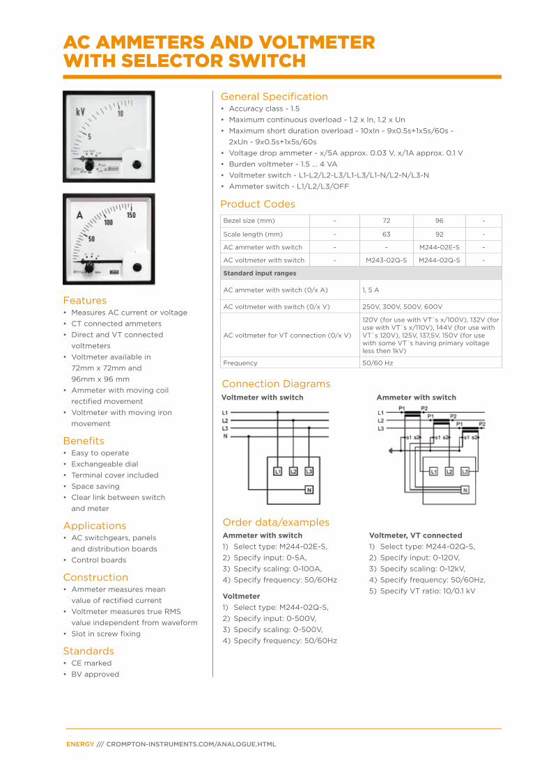
Voltmeter with switch Ammeter with switch
Bezel size (mm) - 72 96 -
Scale length (mm) - 63 92 -
AC ammeter with switch - - M244-02E-S -
AC voltmeter with switch - M243-02Q-S M244-02Q-S -
Standard input ranges
AC ammeter with switch (0/x A) 1, 5 A
AC voltmeter with switch (0/x V) 250V, 300V, 500V, 600V
AC voltmeter for VT connection (0/x V)
120V (for use with VT`s x/100V), 132V (for use with VT`s x/110V), 144V (for use with VT`s 120V), 125V, 137,5V, 150V (for use with some VT`s having primary voltage less then 1kV)
Frequency 50/60 Hz
Order data/examples
Product Codes
Connection Diagrams
Ammeter with switch
1) Select type: M244-02E-S,
2) Specify input: 0-5A,
3) Specify scaling: 0-100A,
4) Specify frequency: 50/60Hz
Voltmeter
1) Select type: M244-02Q-S,
2) Specify input: 0-500V,
3) Specify scaling: 0-500V,
4) Specify frequency: 50/60Hz
Voltmeter, VT connected
1) Select type: M244-02Q-S,
2) Specify input: 0-120V,
3) Specify scaling: 0-12kV,
4) Specify frequency: 50/60Hz,
5) Specify VT ratio: 10/0.1 kV
Features• Measures AC current or voltage
• CT connected ammeters
• Direct and VT connected
voltmeters
• Voltmeter available in
72mm x 72mm and
96mm x 96 mm
• Ammeter with moving coil
rectified movement
• Voltmeter with moving iron
movement
Benefits• Easy to operate
• Exchangeable dial
• Terminal cover included
• Space saving
• Clear link between switch
and meter
Applications• AC switchgears, panels
and distribution boards
• Control boards
Construction• Ammeter measures mean
value of rectified current
• Voltmeter measures true RMS
value independent from waveform
• Slot in screw fixing
Standards• CE marked
• BV approved
General Specification• Accuracy class - 1.5
• Maximum continuous overload - 1.2 x In, 1.2 x Un
• Maximum short duration overload - 10xIn - 9x0.5s+1x5s/60s -
2xUn - 9x0.5s+1x5s/60s
• Voltage drop ammeter - x/5A approx. 0.03 V, x/1A approx. 0.1 V
• Burden voltmeter - 1.5 … 4 VA
• Voltmeter switch - L1-L2/L2-L3/L1-L3/L1-N/L2-N/L3-N
• Ammeter switch - L1/L2/L3/OFF
AC AMMETERS AND VOLTMETER WITH SELECTOR SWITCH
PAGE 7
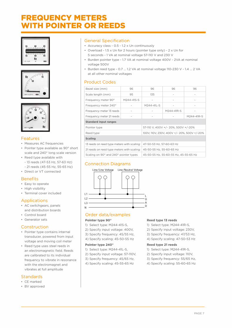
Order data/examples
Product Codes
Connection Diagrams
Pointer type 90°
1) Select type: M244-41S-S,
2) Specify input voltage: 400V,
3) Specify frequency: 45/55 Hz,
4) Specify scaling: 45-50-55 Hz
Pointer type 240°
1) Select type: M244-41L-S,
2) Specify input voltage: 57-110V,
3) Specify frequency: 45/65 Hz,
4) Specify scaling: 45-55-65 Hz
Reed type 13 reeds
1) Select type: M244-41R-S,
2) Specify input voltage: 230V,
3) Specify frequency: 47/53 Hz,
4) Specify scaling: 47-50-53 Hz
Reed type 21 reeds
1) Select type: M244-41R-S,
2) Specify input voltage: 110V,
3) Specify frequency: 55/65 Hz,
4) Specify scaling: 55-60-65 Hz
Bezel size (mm) 96 96 96 96
Scale length (mm) 95 135 - -
Frequency meter 90° M244-41S-S - - -
Frequency meter 240° - M244-41L-S - -
Frequency meter 13 reeds - - M244-41R-S -
Frequency meter 21 reeds - - - M244-41R-S
Standard input ranges
Pointer type 57-110 V, 400V +/- 20%, 500V +/-20%
Reed type 100V, 110V, 230V, 400V +/- 20%, 500V +/-20%
Scaling
13 reeds on reed type meters with scaling: 47-50-53 Hz, 57-60-63 Hz
21 reeds on reed type meters with scaling: 45-50-55 Hz, 55-60-65 Hz
Scaling on 90° and 240° pointer types 45-50-55 Hz, 55-60-55 Hz, 45-55-65 Hz
Features• Measures AC frequencies
• Pointer type available as 90° short
scale and 240° long scale version
• Reed type available with
- 13 reeds (47-53 Hz, 57-63 Hz)
- 21 reeds (45-55 Hz, 55-65 Hz)
• Direct or VT connected
Benefits• Easy to operate
• High visibility
• Terminal cover included
Applications• AC switchgears, panels
and distribution boards
• Control board
• Generator sets
Construction• Pointer type contains internal
transducer, powered from input
voltage and moving coil meter
• Reed type uses steel reeds in
an electromagnetic field. Reeds
are calibrated to its individual
frequency to vibrate in resonance
with the electromagnet and
vibrates at full amplitude
Standards• CE marked
• BV approved
General Specification• Accuracy class - 0.5 - 1.2 x Un continuously
• Overload - 1.5 x Un for 2 hours (pointer type only) - 2 x Un for
5 seconds - 1 VA at nominal voltage 57-110 V and 230 V
• Burden pointer type - 1.7 VA at nominal voltage 400V - 2VA at nominal
voltage 500V
• Burden reed type - 0.7 … 1.2 VA at nominal voltage 110-230 V - 1.4 … 2 VA
at all other nominal voltages
FREQUENCY METERS WITH POINTER OR REEDS
ENERGY /// CROMPTON-INSTRUMENTS.COM/ANALOGUE.HTML
Order data/examples
Product Codes
Connection Diagrams
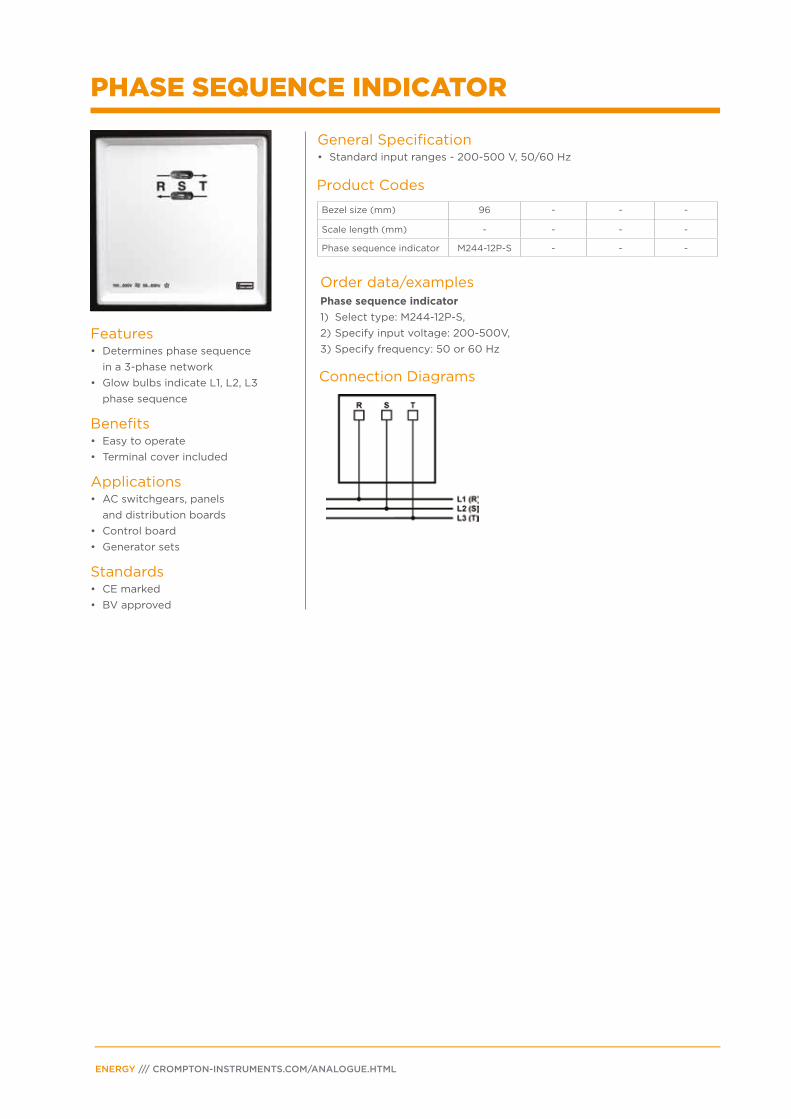
Phase sequence indicator
1) Select type: M244-12P-S,
2) Specify input voltage: 200-500V,
3) Specify frequency: 50 or 60 Hz
Bezel size (mm) 96 - - -
Scale length (mm) - - - -
Phase sequence indicator M244-12P-S - - -
Features• Determines phase sequence
in a 3-phase network
• Glow bulbs indicate L1, L2, L3
phase sequence
Benefits• Easy to operate
• Terminal cover included
Applications• AC switchgears, panels
and distribution boards
• Control board
• Generator sets
Standards• CE marked
• BV approved
General Specification• Standard input ranges - 200-500 V, 50/60 Hz
PHASE SEQUENCE INDICATOR
PAGE 9
Order data/examples
Product Codes
Connection Diagrams
Dual voltmeter - LV direct connected1) Select type: M244-80L-S, 2) Specify input voltage: 500V, 3) Specify scaling: 0-500V, 4) Specify frequency: 50 Hz
Dual voltmeter - VT connected1) Select type: M244-80L-S, 2) Specify input: 0-120V, 3) Specify scaling: 0-12kV, 4) Specify frequency: 50Hz, 5) Specify VT ratio: 10/0.1 kV
Dual frequency meter - pointer type 1) Select type: M244-41D-S, 2) Specify input voltage: 400V, 3) Specify frequency: 45/65 Hz,4) Specify scaling: 45-55-65 Hz
Dual frequency meter - reed type 1) Select type: M244-41E-S, 2) Specify input voltage: 110V, 3) Specify frequency: 55/65 Hz,4) Specify scaling: 55-60-65 Hz
Bezel size (mm) 96 96 96 -
Scale length (mm) 41 41 - -
Voltmeter meter 2 x 90° M244-80L-S - - -
Frequency meter 2 x 90° - M244-41D-S - -
Frequency meter 2 x 21 reeds - - M244-41E-S -
Standard input ranges
Dual voltmeter (direct connected) 300V, 500V
Dual voltmeter (VT connected)
120V (for use with VT`s x/100V), 132V (for use with VT`s x/110V), 144V (for use with VT`s 120V), 125V, 137,5V, 150V (for use with some VT`s having primary voltage less then 1kV)
Dual frequency meter - pointer type 57-110 V, 400V +/- 20%, 500V +/-20%
Dual frequency meter - reed type 100V, 110V, 230V, 400V +/- 20%, 500V +/-20%
Scaling
Dual voltmeter Specify to suit application
Dual frequency meter - pointer type 45-50-55 Hz, 55-60-55 Hz, 45-55-65 Hz
Dual frequency meter - reed type 45-50-55 Hz, 55-60-65 Hz
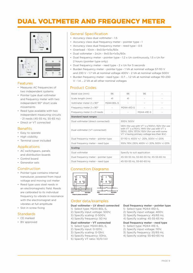
Features• Measures AC frequencies of
two independent systems
• Pointer type dual voltmeter
and frequency meter with two
independent 90° short scale
movements
• Reed type available with two
independent measuring circuits
- 21 reeds (45-55 Hz, 55-65 Hz)
• Direct or VT connected
Benefits• Easy to operate
• High visibility
• Terminal cover included
Applications• AC switchgears, panels
and distribution boards
• Control board
• Generator sets
Construction• Pointer type contains internal
transducer, powered from input
voltage and moving coil meter
• Reed type uses steel reeds in
an electromagnetic field. Reeds
are calibrated to its individual
frequency to vibrate in resonance
with the electromagnet and
vibrates at full amplitude
• Slot in screw fixing
Standards• CE marked
• BV approved
General Specification• Accuracy class dual voltmeter - 1.5
• Accuracy class dual frequency meter - pointer type - 1
• Accuracy class dual frequency meter - reed type - 0.5
• Overload - 10xIn - 9x0.5s+1x5s/60s
• Dual voltmeter - 2xUn - 9x0.5s+1x5s/60s
• Dual frequency meter - pointer type - 1.2 x Un continuously, 1.5 x Un for
2 hours (pointer type only)
• Dual frequency meter - reed type - 2 x Un for 5 seconds
• Burden frequency meter - pointer type - 1 VA at nominal voltage 57-110 V
and 230 V - 1.7 VA at nominal voltage 400V - 2 VA at nominal voltage 500V
• Burden frequency meter - reed type - 0.7 … 1.2 VA at nominal voltage 110-230
V - 1.4 … 2 VA at all other nominal voltages
DUAL VOLTMETER AND FREQUENCY METER
ENERGY /// CROMPTON-INSTRUMENTS.COM/ANALOGUE.HTML
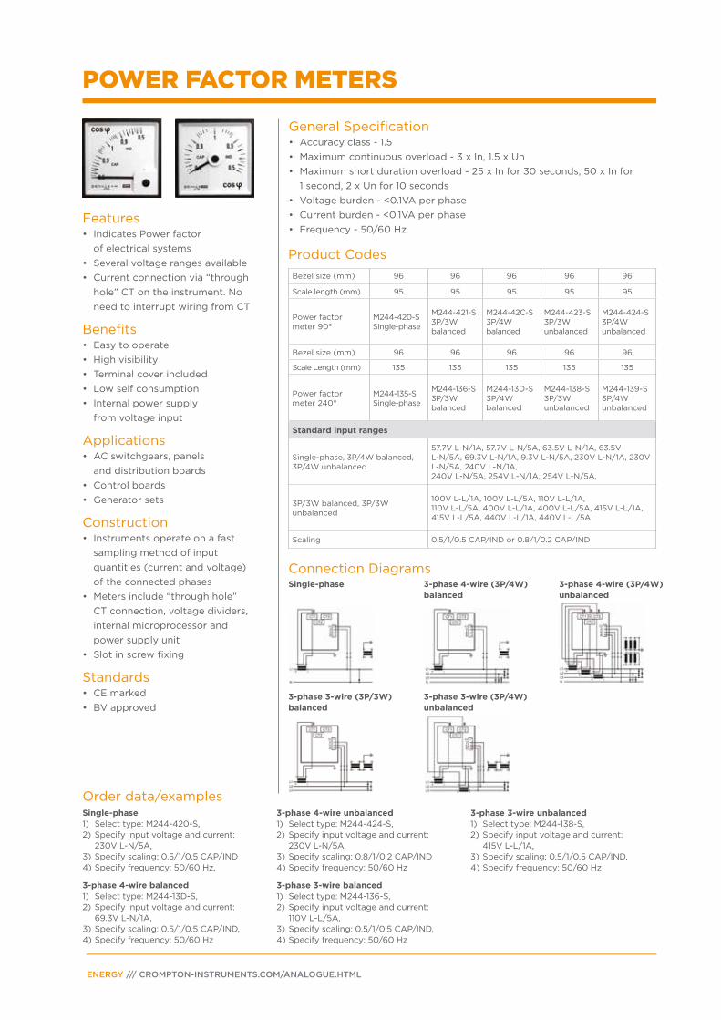
Single-phase 3-phase 4-wire (3P/4W) balanced
3-phase 4-wire (3P/4W) unbalanced
3-phase 3-wire (3P/3W)balanced
3-phase 3-wire (3P/4W)unbalanced
Bezel size (mm) 96 96 96 96 96
Scale length (mm) 95 95 95 95 95
Power factor meter 90°
M244-420-S Single-phase
M244-421-S 3P/3W balanced
M244-42C-S 3P/4W balanced
M244-423-S 3P/3W unbalanced
M244-424-S 3P/4W unbalanced
Bezel size (mm) 96 96 96 96 96
Scale Length (mm) 135 135 135 135 135
Power factor meter 240°
M244-135-S Single-phase
M244-136-S 3P/3W balanced
M244-13D-S 3P/4W balanced
M244-138-S 3P/3W unbalanced
M244-139-S 3P/4W unbalanced
Standard input ranges
Single-phase, 3P/4W balanced, 3P/4W unbalanced
57.7V L-N/1A, 57.7V L-N/5A, 63.5V L-N/1A, 63.5V L-N/5A, 69.3V L-N/1A, 9.3V L-N/5A, 230V L-N/1A, 230V L-N/5A, 240V L-N/1A, 240V L-N/5A, 254V L-N/1A, 254V L-N/5A,
3P/3W balanced, 3P/3W unbalanced
100V L-L/1A, 100V L-L/5A, 110V L-L/1A, 110V L-L/5A, 400V L-L/1A, 400V L-L/5A, 415V L-L/1A, 415V L-L/5A, 440V L-L/1A, 440V L-L/5A
Scaling 0.5/1/0.5 CAP/IND or 0.8/1/0.2 CAP/IND
Order data/examples
Product Codes
Connection Diagrams
Single-phase1) Select type: M244-420-S, 2) Specify input voltage and current:
230V L-N/5A,3) Specify scaling: 0.5/1/0.5 CAP/IND 4) Specify frequency: 50/60 Hz,
3-phase 4-wire balanced1) Select type: M244-13D-S, 2) Specify input voltage and current: 69.3V L-N/1A, 3) Specify scaling: 0.5/1/0.5 CAP/IND, 4) Specify frequency: 50/60 Hz
3-phase 4-wire unbalanced 1) Select type: M244-424-S, 2) Specify input voltage and current: 230V L-N/5A, 3) Specify scaling: 0,8/1/0,2 CAP/IND 4) Specify frequency: 50/60 Hz
3-phase 3-wire balanced 1) Select type: M244-136-S, 2) Specify input voltage and current: 110V L-L/5A,3) Specify scaling: 0.5/1/0.5 CAP/IND, 4) Specify frequency: 50/60 Hz
3-phase 3-wire unbalanced 1) Select type: M244-138-S, 2) Specify input voltage and current: 415V L-L/1A, 3) Specify scaling: 0.5/1/0.5 CAP/IND, 4) Specify frequency: 50/60 Hz
Features• Indicates Power factor
of electrical systems
• Several voltage ranges available
• Current connection via “through
hole” CT on the instrument. No
need to interrupt wiring from CT
Benefits• Easy to operate
• High visibility
• Terminal cover included
• Low self consumption
• Internal power supply
from voltage input
Applications• AC switchgears, panels
and distribution boards
• Control boards
• Generator sets
Construction• Instruments operate on a fast
sampling method of input
quantities (current and voltage)
of the connected phases
• Meters include “through hole”
CT connection, voltage dividers,
internal microprocessor and
power supply unit
• Slot in screw fixing
Standards• CE marked
• BV approved
General Specification• Accuracy class - 1.5
• Maximum continuous overload - 3 x In, 1.5 x Un
• Maximum short duration overload - 25 x In for 30 seconds, 50 x In for
1 second, 2 x Un for 10 seconds
• Voltage burden - <0.1VA per phase
• Current burden - <0.1VA per phase
• Frequency - 50/60 Hz
POWER FACTOR METERS
PAGE 11
Bezel size (mm) 96 96 96 96 96
Scale length (mm) 95 95 95 95 95
Wattmeter 90°M244-210-S Single-phase
M244-211-S 3P/3W balanced
M244-21C-S 3P/4W balanced
M244-213-S 3P/3W unbalanced
M244-214-S 3P/4W unbalanced
Bezel size (mm) 96 96 96 96 96
Scale Length (mm) 135 135 135 135 135
Wattmeter 240°M244-215-S Single-phase
M244-216-S 3P/3W balanced
M244-21D-S 3P/4W balanced
M244-218-S3P/3W unbalanced
M244-219-S 3P/4W unbalanced
Standard input ranges
Single-phase, 3P/4W balanced, 3P/4W unbalanced
57.7V L-N/1A, 57.7V L-N/5A, 63.5V L-N/1A, 63.5V L-N/5A, 230V L-N/1A, 230V L-N/5A, 240V -N/1A, 240V L-N/5A, 254V L-N/1A, 254V L-N/5A,
3P/3W balanced, 3P/3W unbalanced
100V L-L/1A, 100V L-L/5A, 110V L-L/1A, 110V L-L/5A, 400V L-L/1A, 400V L-L/5A, 415V L-L/1A, 415V L-L/5A, 440V L-L/1A, 440V L-L/5A
Electrical system Formula ExampleEnd scale value to
choose (considering 0,6 to 1.2 x S)
Single-phase, direct voltage connection
P = U(L-N) x Ip x cos φ
P = 230V x 50A x 0.9 = 10350 W = 10.35 kW
10 kW
3-phase 4-wire, direct voltage connection (balanced or unbalanced)
P = 3 x U(L-N) x Ip x cos φ
P = 3 x 230V x 400A x 0.95 = 262200 W = 262,2 kW
250 kW
3-phase 3-wire, direct voltage connection (balanced or unbalanced)
P = 1.732 x U(L-L) x Ip x cos φ
P = 1.732 x 400V x 1000A x 0,9 = 623520 W = 623,52 kW
600 kW
3-phase 4-wire, voltage connection via VT (balanced or unbalanced)
P = 3 x Up(L-N) x Ip x cos φ
P = 3 x 5770V x 100A x 0.95 = 1644450 W = 1,64445 MW
1.5 MW
3-phase 3-wire, voltage connection via VT (balanced or unbalanced)
P = 1.732 x Up(L-L) x Ip x cos φ
P = 1.732 x 30000V x 50A x 0,9 = 2338200 W = 2,3382 MW
2,5 MW
Order data/examples
Product Codes
Single-phase1) Select type: M244-210-S, 2) Specify input voltage and CT ratio:
230V L-N, 50/5A,3) Specify scaling: 0-10 kW, 4) Specify frequency: 50/60 Hz,
3-phase 4-wire balanced or 3-phase 4-wire unbalanced1) Select type: M244-21D-S, 2) Specify input voltage and CT ratio: 230 V L-N, 400/5A,3) Specify scaling: 0-250 kW, 4) Specify frequency: 50/60 Hz
3-phase 3-wire balanced or unbalanced 1) Select type: M244-213-S, 2) Specify input voltage and CT ratio:
400V L-L, 1000/1A,3) Specify scaling: 0-600 kW, 4) Specify frequency: 50/60 Hz
3-phase 4-wire balanced or unbalanced, VT connected 1) Select type: M244-214-S, 2) Specify VT ratio and CT ratio:
5770/57.7V L-N, 100/5A,3) Specify scaling: 0-1.5 MW, 4) Specify frequency: 50/60 Hz
3-phase 3-wire balanced or unbalanced 1) Select type: M244-218-S, 2) Specify input VT ratio and CT ratio:
30000/110V L-L, 50/1A,3) Specify scaling: 0-2.5 MW 4) Specify frequency: 50/60 Hz
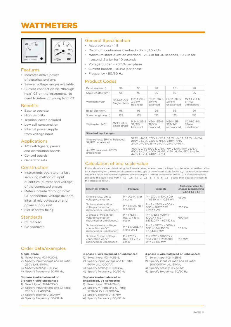
Features• Indicates active power
of electrical systems
• Several voltage ranges available
• Current connection via “through
hole” CT on the instrument. No
need to interrupt wiring from CT
Benefits• Easy to operate
• High visibility
• Terminal cover included
• Low self consumption
• Internal power supply
from voltage input
Applications• AC switchgears, panels
and distribution boards
• Control boards
• Generator sets
Construction• Instruments operate on a fast
sampling method of input
quantities (current and voltage)
of the connected phases
• Meters include “through hole”
CT connection, voltage dividers,
internal microprocessor and
power supply unit
• Slot in screw fixing
Standards• CE marked
• BV approved
General Specification• Accuracy class - 1.5
• Maximum continuous overload - 3 x In, 1.5 x Un
• Maximum short duration overload - 25 x In for 30 seconds, 50 x In for
1 second, 2 x Un for 10 seconds
• Voltage burden - <0.1VA per phase
• Current burden - <0.1VA per phase
• Frequency - 50/60 Hz
Calculation of end scale valueEnd scale value is calculated using the formula below, where correct voltage must be selected (either L-N or L-L), depending on the electrical system and the type of meter used. Scale factor, e.g. the relation between end scale value and nominal apparent power (cos-phi = 1) must be between 0.6 to 1.2. It is recommended selecting the scale value from 1 - 1.2 - 1.25 - 1.5 - 2 - 2.5 - 3 - 4 - 5 - 6 - 7.5 – 8 (and their decades) closest to the calculated result..
WATTMETERS
ENERGY /// CROMPTON-INSTRUMENTS.COM/ANALOGUE.HTML
Bezel size (mm) 96 96 96 96 96
Scale Length (mm) 95 95 95 95 95
Varmeter 90°M244-310-S Single-phase
M244-311-S 3P/3W balanced
M244-31C-S 3P/4W balanced
M244-313-S 3P/3W unbalanced
M244-314-S 3P/4W unbalanced
Bezel size (mm) 96 96 96 96 96
Scale length (mm) 135 135 135 135 135
Varmeter 240°M244-315-S Single-phase
M244-316-S 3P/3W balanced
M244-31D-S 3P/4W balanced
M244-318-S 3P/3W unbalanced
M244-319-S 3P/4W unbalanced
Standard input ranges
Single-phase, 3P/4W balanced, 3P/4W unbalanced
57.7V L-N/1A, 57.7V L-N/5A, 63.5V L-N/1A, 63.5V L-N/5A, 230V L-N/1A, 230V L-N/5A, 240V L-N/1A, 240V L-N/5A, 254V L-N/1A, 254V L-N/5A,
3P/3W balanced, 3P/3W unbalanced100V L-L/1A, 100V L-L/5A, 110V L-L/1A, 110V L-L/5A, 400V L-L/1A, 400V L-L/5A, 415V L-L/1A, 415V L-L/5A, 440V L-L/1A, 440V L-L/5A
Electrical system Formula ExampleEnd scale value to
choose (considering 0,6 to 1.2 x S)
Single-phase, direct voltage connection
Q = U(L-N) x Ip x sin φ
Q = 230V x 50A x 0.44 = 5060 var = 5,06 kvar
6 kvar
3-phase 4-wire, direct voltage connection (balanced or unbalanced)
Q = 3 x U(L-N) x Ip x sin φ
P = 3 x 230V x 400A x 0.31 = 85560 var = 85,56 kvar
200 kvar
3-phase 3-wire, direct voltage connection (balanced or unbalanced)
Q = 1.732 x U(L-L) x Ip x sin φ
P = 1.732 x 400V x 1000A x 0,44 = 304832 var = 304,8 kvar
500 kvar
3-phase 4-wire, voltage connection via VT (balanced or unbalanced)
Q = 3 x Up(L-N) x Ip x sin φ
P = 3 x 5770V x 100A x 0.199 = 344469 var = 344,469 kvar
1 Mvar
3-phase 3-wire, voltage connection via VT (balanced or unbalanced)
Q = 1.732 x Up(L-L) x Ip x sin φ
P = 1.732 x 30000V x 50A x 0,44 = 1143120 var = 1,14312 Mvar
2 Mvar
Order data/examples
Product Codes
Single-phase1) Select type: M244-310-S, 2) Specify input voltage and CT ratio:
230V L-N, 50/5A,3) Specify scaling: 0-6 kvar, 4) Specify frequency: 50/60 Hz,
3-phase 4-wire balanced or 3-phase 4-wire unbalanced1) Select type: M244-31D-S, 2) Specify input voltage and CT ratio:
230 V L-N, 400/5A,3) Specify scaling: 0-200 kvar, 4) Specify frequency: 50/60 Hz
3-phase 3-wire balanced or unbalanced 1) Select type: M244-313-S, 2) Specify input voltage and CT ratio:
400V L-L, 1000/1A,3) Specify scaling: 0-500 kvar, 4) Specify frequency: 50/60 Hz
3-phase 4-wire balanced or unbalanced, VT connected 1) Select type: M244-314-S, 2) Specify VT ratio and CT ratio:
5770/57.7V L-N, 100/5A,3) Specify scaling: 0-1 Mvar, 4) Specify frequency: 50/60 Hz
3-phase 3-wire balanced or unbalanced 1) Select type: M244-318-S, 2) Specify input VT ratio and CT ratio:
30000/110V L-L, 50/1A,3) Specify scaling: 0-2 Mvar, 4) Specify frequency: 50/60 Hz
Features• Indicates reactive power of
electrical systems
• Several voltage ranges available
• Current connection via “through
hole” CT on the instrument. No
need to interrupt wiring from CT.
Benefits• Easy to operate
• High visibility
• Terminal cover included
• Low self consumption
• Internal power supply from
voltage input
Applications• AC switchgears, panels and
distribution boards
• Control boards
• Generator sets
Construction• Instruments operate on a fast
sampling method of input
quantities (current and voltage) of
the connected phases.
• Meters include “through hole”
CT connection, voltage dividers,
internal microprocessor and power
supply unit.
• Slot in screw fixing
Standards• CE marked
• BV approved
General Specification• Accuracy class - 1.5
• Maximum continuous overload - 3 x In, 1.5 x Un
• Maximum short duration overload - 25 x In for 30 seconds, 50 x In for
1 second, 2 x Un for 10 seconds
• Voltage burden - <0.1VA per phase
• Current burden - <0.1VA per phase
• Frequency - 50/60 Hz
Calculation of end scale valueEnd scale value is calculated using the formula below, where correct voltage must be selected (either L-N or L-L), depending on the electrical system and the type of meter used. Scale factor, e.g. the relation between end scale value and nominal apparent power (cos-phi = 1) must be between 0.6 to 1.2. It is recommended selecting the scale value from 1 - 1.2 - 1.25 - 1.5 - 2 - 2.5 - 3 - 4 - 5 - 6 - 7.5 – 8 (and their decades) closest to the calculated result..
Ip = CT primary current, Up = VT primary voltage, U = direct connected voltage, sin φ = power factor
VARMETERS
PAGE 13
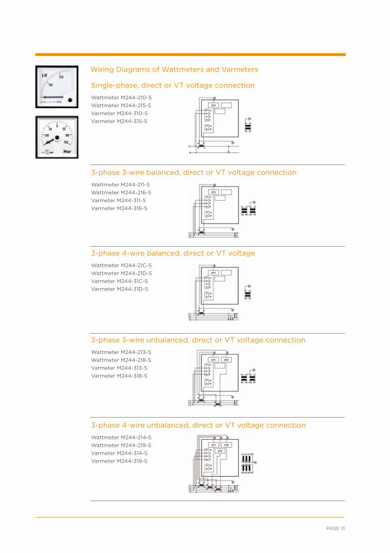
Single-phase, direct or VT voltage connection
Wattmeter M244-210-S
Wattmeter M244-215-S
Varmeter M244-310-S
Varmeter M244-315-S
3-phase 3-wire balanced, direct or VT voltage connection
Wattmeter M244-211-S
Wattmeter M244-216-S
Varmeter M244-311-S
Varmeter M244-316-S
3-phase 4-wire balanced, direct or VT voltage
Wattmeter M244-21C-S
Wattmeter M244-21D-S
Varmeter M244-31C-S
Varmeter M244-31D-S
3-phase 3-wire unbalanced, direct or VT voltage connection
Wattmeter M244-213-S
Wattmeter M244-218-S
Varmeter M244-313-S
Varmeter M244-318-S
3-phase 4-wire unbalanced, direct or VT voltage connection
Wattmeter M244-214-S
Wattmeter M244-219-S
Varmeter M244-314-S
Varmeter M244-319-S
Wiring Diagrams of Wattmeters and Varmeters
ENERGY /// CROMPTON-INSTRUMENTS.COM/ANALOGUE.HTML
Bezel size (mm) 96 96 96 96 96
Scale length (mm) 95 95 95 95 95
Active energy meter with Wattmeter 90°
M244-HWG-S Single-phase
M244-HWH-S 3P/3W balanced
M244-HWV-S 3P/4W balanced
M244-HWJ-S 3P/3W unbalanced
M244-HWK-S 3P/4W unbalanced
Bezel size (mm) 96 96 96 96 96
Scale Length (mm) 135 135 135 135 135
Active energy meter with Wattmeter 240°
M244-HWB-S Single-phase
M244-HWC-S 3P/3W balanced
M244-HWU-S 3P/4W balanced
M244-HWD-S 3P/3W unbalanced
M244-HWE-S 3P/4W unbalanced
Standard input ranges
Single-phase, 3P/4W balanced & unbalanced
57.7V L-N/1A, 57.7V L-N/5A, 63.5V L-N/1A, 63.5V L-N/5A, 230V L-N/1A, 230V L-N/5A, 240V L-N/1A, 240V L-N/5A, 254V L-N/1A, 254V L-N/5A,
3P/3W balanced & unbalanced1100V L-L/1A, 100V L-L/5A, 110V L-L/1A, 110V L-L/5A, 400V L-L/1A, 400V L-L/5A, 415V L-L/1A, 415V L-L/5A, 440V L-L/1A, 440V L-L/5A
Electrical system Formula ExampleEnd scale value to
choose (considering 0,6 to 1.2 x S)
Single-phase, direct voltage connection
P = U(L-N) x Ip x cos φ
P = 230V x 50A x 0.9 = 10350 W = 10.35 kW
10 kW
3-phase 4-wire, direct voltage connection (balanced or unbalanced)
P = 3 x U(L-N) x Ip x cos φ
P = 3 x 230V x 400A x 0.95 = 262200 W = 262.2 kW
250 kW
3-phase 3-wire, direct voltage connection (balanced or unbalanced)
P = 1.732 x U(L-L) x Ip x cos φ
P = 1.732 x 400V x 1000A x 0,9 = 623520 W = 623.52 kW
600 kW
3-phase 4-wire, voltage connection via VT (balanced or unbalanced)
P = 3 x Up(L-N) x Ip x cos φ
P = 3 x 5770V x 100A x 0.95 = 1644450 W = 1.64445 MW
1.5 MW
3-phase 3-wire, voltage connection via VT (balanced or unbalanced)
P = 1.732 x Up(L-L) x Ip x cos φ
P = 1.732 x 30000V x 50A x 0,9 = 2338200 W = 2.3382 MW
2,5 MW
Order data/examples
Product Codes
General Specification
Single-phase1) Select type: M244-HWG-S,2) Specify input voltage and CT ratio:
230V L-N, 50/5A,3) Spec. scaling: 0-10 kW,4) Spec. frequency: 50/60 Hz, 5) Select pulse rate: 1p/10kWh,6) Select output: 1 pulsed output
3-phase 4-wire balanced or3-phase 4-wire unbalanced1) Select type: M244-HWK-S,2) Specify input voltage and CT ratio:
230 V L-N, 400/5A,3) Spec. scaling: 0-250 kW,4) Spec. frequency: 50/60 Hz,
5) Select pulse rate: 1p/10kWh,6) Select output: 1 puls. o/p
3-phase 3-wire balanced or unbalanced1) Select type: M244-HWJ-S,2) Specify input voltage and CT ratio:
400V L-L, 1000/1A,3) Spec. scaling: 0-600 kW,4) Spec. frequency: 50/60 Hz , 5) Select pulse rate: 1p/10kWh,6) Select output: 1 puls. o/p
3-phase 4-wire balanced orunbalanced, VT connected1) Select type: M244-HWU-S,
2) Specify VT ratio and CT ratio: 5770/57.7V L-N, 100/5A,
3) Spec. scaling: 0-1.5 MW,4) Spec. frequency: 50/60 Hz, 5) Select pulse rate: 1p/100kWh,6) Select output: 1 pulsed output
3-phase 3-wire balanced or unbalanced1) Select type: M244-HWD-S,2) Specify input VT ratio and CT ratio:
30000/110V L-L, 50/1A,3) Spec. scaling: 0-2.5MW 4) Spec. frequency: 50/60 Hz, 5) Select pulse rate: 1p/100kWh,6) Select output: 1 pulsed output
Features• Counts electrical active energy
and indicates active power of
electrical systems
• Several voltage ranges available
• Current connection via “through
hole” CT on the instrument. No
need to interrupt wiring from CT
• Pulsed output as standard
Benefits• High visibility
• Terminal cover included
• Low self consumption
• Separated power supply
Applications• AC switchgears, panels and
distribution boards
• Control boards
• Generator sets
Construction• Instruments operate on a fast
sampling method of input
quantities (current and voltage)
of the connected phases
• Meters include “through hole”
CT connection, voltage dividers,
internal microprocessor and
power supply unit
• Slot in screw fixing
Standards• CE marked
• BV approved
• Accuracy class active power meter - 1.5
• Accuracy class active energy meter
- 1 to EN 62053-21
• Maximum continuous overload
- 2 x In, 1.2 x Un
• Nominal frequency - 50/60 Hz
• Voltage burden - <0.1VA per phase
• Current burden - <0.1VA per phase
• Power supply - 120-300 VDC/85-264 VAC
• Frequency - 40-65 Hz
• Voltage burden - <3 VA
• Pulsed output - 1 S0 pulsed output with
1p/10kWh, 1p/100kWh, 1p/10MWh,
1p/100MWh. Maximum pulse rate may
not exceed 33 pulses per second (1980
pulses per minute). If in doubt choose
next higher value, e.g. 1p/100/kWh
instead of 1p/10kWh
Calculation of end scale valueEnd scale value is calculated using the formula below, where correct voltage must be selected (either L-N or L-L), depending on the electrical system and the type of meter used. Scale factor, e.g. the relation between end scale value and nominal apparent power (cos-phi = 1) must be between 0.6 to 1.2. It is recommended selecting the scale value from 1 - 1.2 - 1.25 - 1.5 - 2 - 2.5 - 3 - 4 - 5 - 6 - 7.5 – 8 (and their decades) closest to the calculated result..
Ip = CT primary current, Up = VT primary voltage, U = direct connected voltage, cos φ = power factor
ACTIVE ENERGY METER WITH POWER INDICATOR
PAGE 15
Bezel size (mm) 96 96 96 96 96
Scale length (mm) 95 95 95 95 95
Reactive energy meter with Varmeter 90°
M244-HXG-S Single-phase
M244-HXH-S 3P/3W balanced
M244-HXV-S 3P/4W balanced
M244-HXJ-S 3P/3W unbalanced
M244-HXK-S 3P/4W unbalanced
Bezel size (mm) 96 96 96 96 96
Scale Length (mm) 135 135 135 135 135
Reactive energy meterwith Varmeter 240°
M244-HXB-S Single-phase
M244-HXC-S 3P/3W balanced
M244-HXU-S 3P/4W balanced
M244-HXD-S 3P/3W unbalanced
M244-HXE-S 3P/4W unbalanced
Standard input ranges
Single-phase, 3P/4W balanced & unbalanced
57.7V L-N/1A, 57.7V L-N/5A, 63.5V L-N/1A, 63.5V L-N/5A, 230V L-N/1A, 230V L-N/5A, 240V L-N/1A, 240V L-N/5A, 254V L-N/1A, 254V L-N/5A,
3P/3W balanced & unbalanced100V L-L/1A, 100V L-L/5A, 110V L-L/1A, 110V L-L/5A, 400V L-L/1A, 400V L-L/5A, 415V L-L/1A, 415V L-L/5A, 440V L-L/1A, 440V L-L/5A
Electrical system Formula ExampleEnd scale value to
choose (considering 0,6 to 1.2 x S)
Single-phase, direct voltage connection
P = U(L-N) x Ip x sin φ
Q = 230V x 50A x 0.44 = 5060 var = 5.06 kvar
6 kvar
3-phase 4-wire, direct voltage connection (balanced or unbalanced)
P = 3 x U(L-N) x Ip x sin φ
P = 3 x 230V x 400A x 0.31 = 85560 var = 85.56 kvar
200 kvar
3-phase 3-wire, direct voltage connection (balanced or unbalanced)
P = 1.732 x U(L-L) x Ip x sin φ
P = 1.732 x 400V x 1000A x 0,44 = 304832 var = 304.8 kvar
500 kvar
3-phase 4-wire, voltage connection via VT (balanced or unbalanced)
P = 3 x Up(L-N) x Ip x sin φ
P = 3 x 5770V x 100A x 0.199 = 344469 var = 344.469 kvar
1 Mvar
3-phase 3-wire, voltage connection via VT (balanced or unbalanced)
P = 1.732 x Up(L-L) x Ip x sin φ
P = 1.732 x 30000V x 50A x 0,44 = 1143120 var = 1.14312 Mvar
2 Mvar
Order data/examples
Product Codes
General Specification
Single-phase1) Select type: M244-HXG-S,2) Specify input voltage and CT ratio:
230V L-N, 50/5A,3) Spec. scaling: 0-6kvar,4) Spec. frequency: 50/60 Hz, 5) Select pulse rate: 1p/10kvarh,6) Select output: 1 pulsed output
3-phase 4-wire balanced or3-phase 4-wire unbalanced1) Select type: M244-HXK-S,2) Specify input voltage and CT ratio:
230 V L-N, 400/5A,3) Spec. scaling: 0-200kvar,
4) Spec. frequency: 50/60 Hz, 5) Select pulse rate: 1p/10kvarh,6) Select output: 1 pul. O/P
3-phase 3-wire balanced or unbalanced1) Select type: M244-HXJ-S,2) Spec. input voltage and CT ratio:
400V L-L, 1000/1A,3) Spec. scaling: 0-500 kvar,4) Spec. frequency: 50/60 Hz , 5) Select pulse rate: 1p/10kvarh,6) Select output: 1 pul. O/P
3-phase 4-wire balanced orunbalanced, VT connected1) Select type: M244-HXU-S,
2) Specify VT ratio and CT ratio: 5770/57.7V L-N, 100/5A,
3) Spec. scaling: 0-1 Mvar,4) Spec. frequency: 50/60 Hz, 5) Select pulse rate: 1p/100kvarh,6) Select output: 1 pul. O/P
3-phase 3-wire balanced or unbalanced1) Select type: M244-HXD-S,2) Specify input VT ratio and CT ratio:
30000/110V L-L, 50/1A,3) Spec.scaling: 0-2 Mvar4) Spec. frequency: 50/60 Hz, 5) Select pulse rate: 1p/100kWh,6) Select output: 1 pulsed O/P
Features• Counts electrical reactive energy
and indicates reactive power of
electrical systems
• Several voltage ranges available
• Current connection via “through
hole” CT on the instrument. No
need to interrupt wiring from CT
• Pulsed output as standard
Benefits• High visibility
• Terminal cover included
• Low self consumption
• Separated power supply
Applications• AC switchgears, panels and
distribution boards
• Control boards
• Generator sets
Construction• Instruments operate on a fast
sampling method of input
quantities (current and voltage)
of the connected phases
• Meters include “through hole”
CT connection, voltage dividers,
internal microprocessor and
power supply unit
• Slot in screw fixing
Standards• CE marked
• BV approved
• Accuracy class reactive power meter - 1.5
• Accuracy class reactive energy meter
- 2 to EN 62053-23
• Maximum continuous overload
- 2 x In, 1.2 x Un
• Nominal frequency - 50/60 Hz
• Voltage burden - <0.1VA per phase
• Current burden - <0.1VA per phase
• Power supply - 120-300 VDC / 85-264 VAC
• Frequency - 40-65 Hz
• Voltage burden - <3 VA
• Pulsed output - 1 S0 pulsed output
with 1p/10kWh, 1p/100kWh, 1p/10MWh,
1p/100MWh. Maximum pulse rate may
not exceed 33 pulses per second (1980
pulses per minute). If in doubt choose
next higher value, e.g. 1p/100/kWh
instead of 1p/10kWh
Calculation of end scale valueEnd scale value is calculated using the formula below, where correct voltage must be selected (either L-N or L-L), depending on the electrical system and the type of meter used. Scale factor, e.g. the relation between end scale value and nominal apparent power (cos-phi = 1) must be between 0.6 to 1.2. It is recommended selecting the scale value from 1 - 1.2 - 1.25 - 1.5 - 2 - 2.5 - 3 - 4 - 5 - 6 - 7.5 – 8 (and their decades) closest to the calculated result..
Ip = CT primary current, Up = VT primary voltage, U = direct connected voltage, sin φ = power factor
REACTIVE ENERGY METER WITH POWER INDICATOR
ENERGY /// CROMPTON-INSTRUMENTS.COM/ANALOGUE.HTML
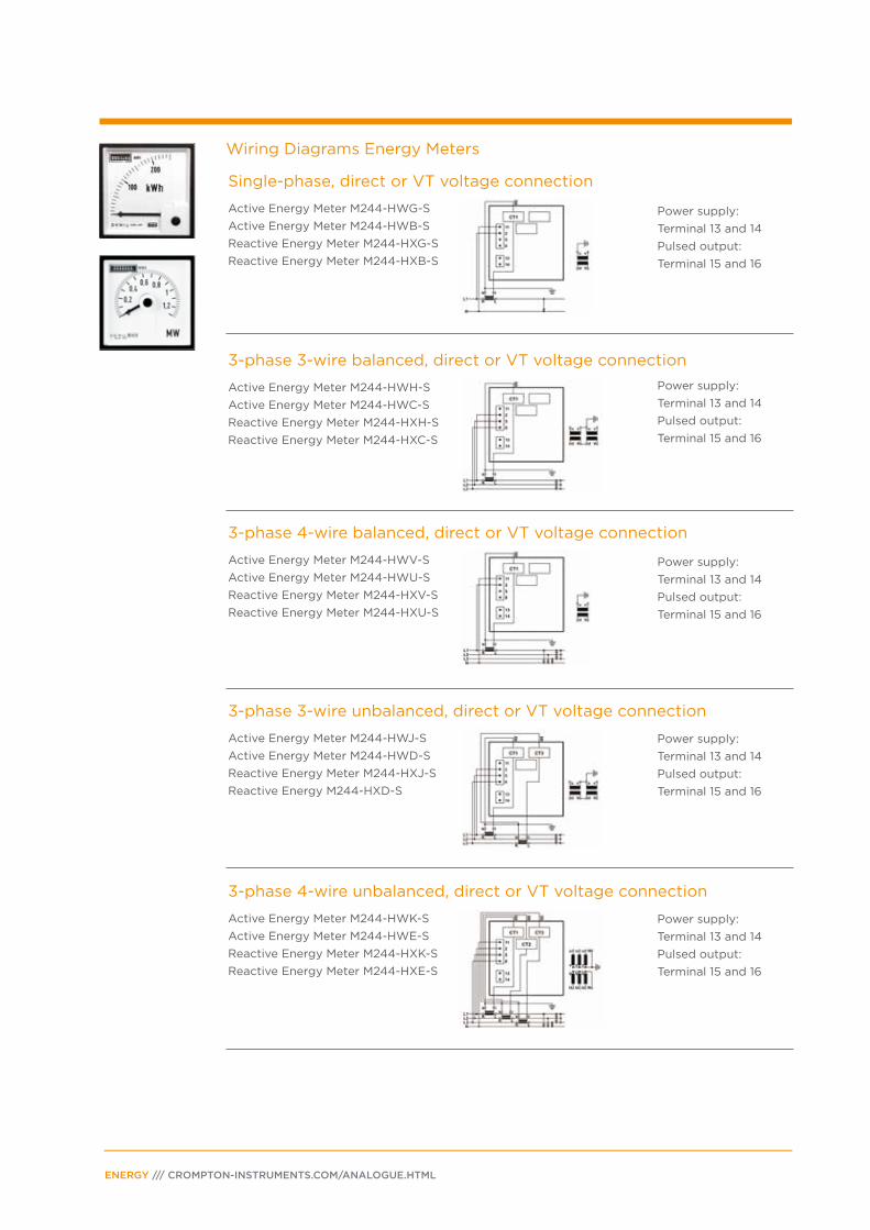
Single-phase, direct or VT voltage connection
Active Energy Meter M244-HWG-S
Active Energy Meter M244-HWB-S
Reactive Energy Meter M244-HXG-S
Reactive Energy Meter M244-HXB-S
Power supply:
Terminal 13 and 14
Pulsed output:
Terminal 15 and 16
Power supply:
Terminal 13 and 14
Pulsed output:
Terminal 15 and 16
Power supply:
Terminal 13 and 14
Pulsed output:
Terminal 15 and 16
Power supply:
Terminal 13 and 14
Pulsed output:
Terminal 15 and 16
Power supply:
Terminal 13 and 14
Pulsed output:
Terminal 15 and 16
3-phase 3-wire balanced, direct or VT voltage connection
Active Energy Meter M244-HWH-S
Active Energy Meter M244-HWC-S
Reactive Energy Meter M244-HXH-S
Reactive Energy Meter M244-HXC-S
3-phase 4-wire balanced, direct or VT voltage connection
Active Energy Meter M244-HWV-S
Active Energy Meter M244-HWU-S
Reactive Energy Meter M244-HXV-S
Reactive Energy Meter M244-HXU-S
3-phase 3-wire unbalanced, direct or VT voltage connection
Active Energy Meter M244-HWJ-S
Active Energy Meter M244-HWD-S
Reactive Energy Meter M244-HXJ-S
Reactive Energy M244-HXD-S
3-phase 4-wire unbalanced, direct or VT voltage connection
Active Energy Meter M244-HWK-S
Active Energy Meter M244-HWE-S
Reactive Energy Meter M244-HXK-S
Reactive Energy Meter M244-HXE-S
Wiring Diagrams Energy Meters
PAGE 17
Bezel size (mm) 96 96 96
M244-14A-S LED only
M244-14L-S LED & synchro check relay
M244-14D-S LED & synchro check relay with deadbus option
Bezel size (mm) 96 96 96
M244- 4M-S LED & synchro check relay & LCD
M244-14E-S LED & synchro check relay with deadbus option & LCD display
Standard input ranges
Voltage 100V L/L, 110V L/L400V L/L, 415 V L/L, 440V L/L
Order data/examples
Product Codes
General Specification
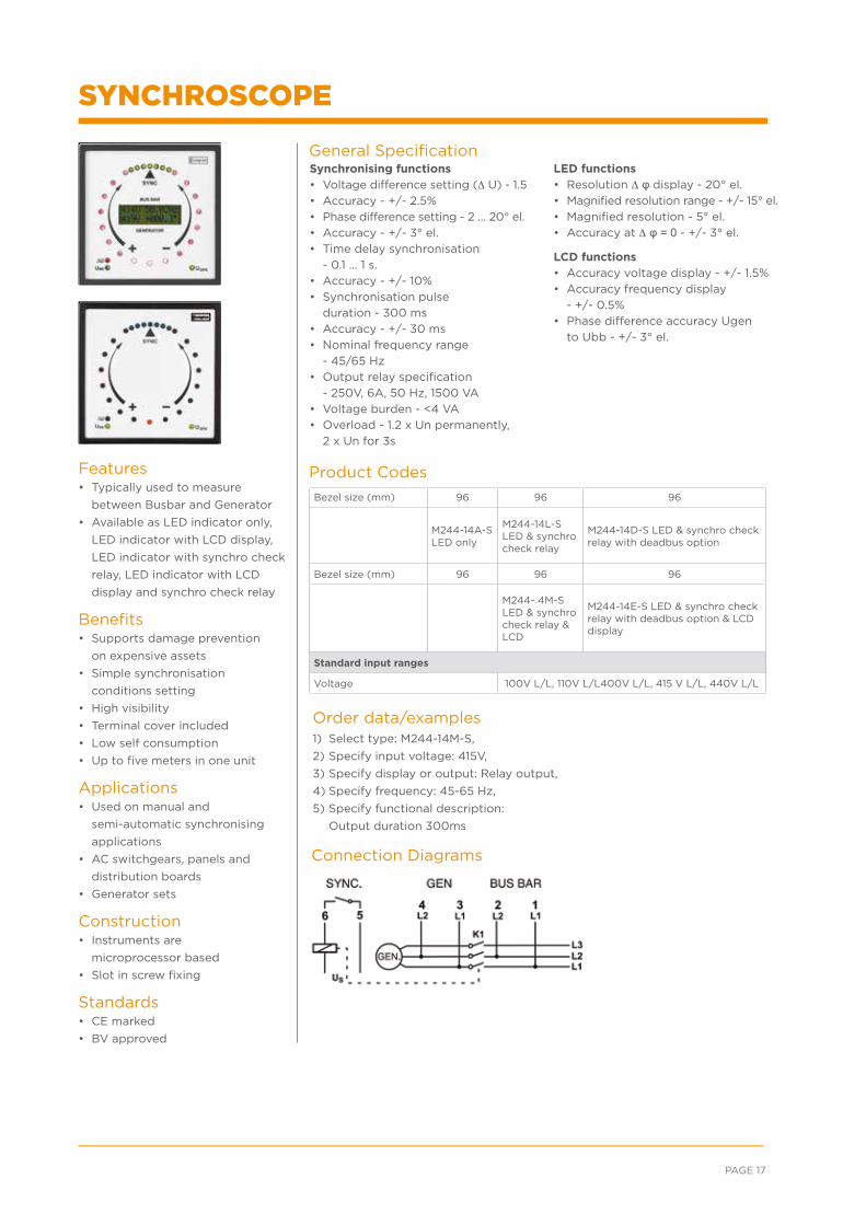
Connection Diagrams
1) Select type: M244-14M-S,
2) Specify input voltage: 415V,
3) Specify display or output: Relay output,
4) Specify frequency: 45-65 Hz,
5) Specify functional description:
Output duration 300ms
Features• Typically used to measure
between Busbar and Generator
• Available as LED indicator only,
LED indicator with LCD display,
LED indicator with synchro check
relay, LED indicator with LCD
display and synchro check relay
Benefits• Supports damage prevention
on expensive assets
• Simple synchronisation
conditions setting
• High visibility
• Terminal cover included
• Low self consumption
• Up to five meters in one unit
Applications• Used on manual and
semi-automatic synchronising
applications
• AC switchgears, panels and
distribution boards
• Generator sets
Construction• Instruments are
microprocessor based
• Slot in screw fixing
Standards• CE marked
• BV approved
Synchronising functions• Voltage difference setting (∆ U) - 1.5
• Accuracy - +/- 2.5%
• Phase difference setting - 2 … 20° el.
• Accuracy - +/- 3° el.
• Time delay synchronisation
- 0.1 … 1 s.
• Accuracy - +/- 10%
• Synchronisation pulse
duration - 300 ms
• Accuracy - +/- 30 ms
• Nominal frequency range
- 45/65 Hz
• Output relay specification
- 250V, 6A, 50 Hz, 1500 VA
• Voltage burden - <4 VA
• Overload - 1.2 x Un permanently,
2 x Un for 3s
LED functions • Resolution ∆ φ display - 20° el.
• Magnified resolution range - +/- 15° el.
• Magnified resolution - 5° el.
• Accuracy at ∆ φ = 0 - +/- 3° el.
LCD functions • Accuracy voltage display - +/- 1.5%
• Accuracy frequency display
- +/- 0.5%
• Phase difference accuracy Ugen
to Ubb - +/- 3° el.
SYNCHROSCOPEWiring Diagrams Energy Meters
ENERGY /// CROMPTON-INSTRUMENTS.COM/ANALOGUE.HTML
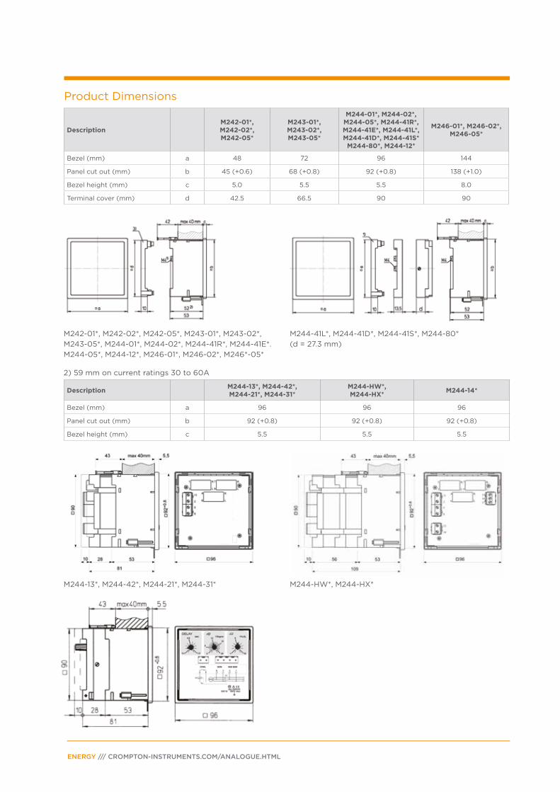
Product Dimensions
M242-01*, M242-02*, M242-05*, M243-01*, M243-02*,
M243-05*, M244-01*, M244-02*, M244-41R*, M244-41E*.
M244-05*, M244-12*, M246-01*, M246-02*, M246*-05*
2) 59 mm on current ratings 30 to 60A
M244-41L*, M244-41D*, M244-41S*, M244-80*
(d = 27.3 mm)
M244-13*, M244-42*, M244-21*, M244-31* M244-HW*, M244-HX*
DescriptionM242-01*, M242-02*, M242-05*
M243-01*, M243-02*, M243-05*
M244-01*, M244-02*, M244-05*, M244-41R*, M244-41E*, M244-41L*, M244-41D*, M244-41S*
M244-80*, M244-12*
M246-01*, M246-02*, M246-05*
Bezel (mm) a 48 72 96 144
Panel cut out (mm) b 45 (+0.6) 68 (+0.8) 92 (+0.8) 138 (+1.0)
Bezel height (mm) c 5.0 5.5 5.5 8.0
Terminal cover (mm) d 42.5 66.5 90 90
DescriptionM244-13*, M244-42*, M244-21*, M244-31*
M244-HW*, M244-HX*
M244-14*
Bezel (mm) a 96 96 96
Panel cut out (mm) b 92 (+0.8) 92 (+0.8) 92 (+0.8)
Bezel height (mm) c 5.5 5.5 5.5
PAGE 19
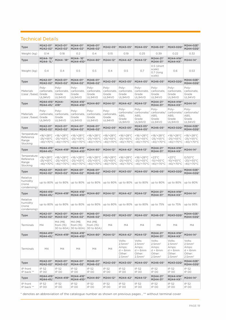
Technical Details
TypeM242-01* M242-02*
M243-01* M243-02*
M244-01* M244-02*
M246-01* M246-02*
M242-05* M243-05* M244-05* M246-05* M243-02Q*M244-02E* M244-02Q*
Weight (kg) 0.14 0.18 0.2 0.4 0.15 0.19 0.25 0.39 0.22 0.32
TypeM244- 1S* M244- 1L*
M244- 1R* M244- 1E* M244-41D*
M244-80* M244-12* M244-42* M244-13*M244-21*M244-31*
M244-HW*M244-HX*
M244-14*
Weight (kg) 0.4 0.4 0.5 0.5 0.4 0.5 0.7
0.5 (short scale)0.7 (long scale)
0.6 0.53
TypeM242-01*M242-02*
M243-01*M243-02*
M244-01*M244-02*
M246-01*M246-02*
M242-05* M243-05* M244-05* M246-05* M243-02Q*M244-02E*M244-02Q*
Materials (case´/base)
Poly-carbonate, Grade UL94V0
Poly-carbonate, Grade UL94V0
Poly-carbonate, Grade UL94V0
Poly-carbonate, Grade UL94V0
Poly-carbonate, Grade UL94V0
Poly-carbonate, Grade UL94V0
Poly-carbonate, Grade UL94V0
Poly-carbonate, Grade UL94V0
Poly-carbonate, Grade UL94V0
Poly-carbonate, Grade UL94V0
TypeM244-41S*M244-41L*
M244-41R*
M244-41E*M244-41D*
M244-80* M244-12* M244-42* M244-13*M244-21*M244-31*
M244-HW*M244-HX*
M244-14*
Materials (case´/base)
Poly-carbonate, Grade UL94V0
Poly-carbonate, Grade UL94V0
Poly-carbonate, Grade UL94V0
Poly-carbonate, Grade UL94V0
Poly-carbonate, Grade UL94V0
Poly-carbonate/ABS, Grade UL94V0
Poly-carbonate/ABS, Grade UL94V0
Poly-carbonate/ABS, Grade UL94V0
Poly-carbonate/ABS, Grade UL94V0
Poly-carbonate/ABS, Grade UL94V0
TypeM242-01*M242-02*
M243-01*M243-02*
M244-01*M244-02*
M246-01*M246-02*
M242-05* M243-05*M243-05* M244-05*
M246-05* M243-02Q*M244-02E*M244-02Q*
Temperature:ReferenceRangeStocking
+18/+28°C-25/+55°C–40/+70°C
+18/+28°C-25/+55°C–40/+70°C
+18/+28°C-25/+55°C–40/+70°C
+18/+28°C-25/+55°C–40/+70°C
+18/+28°C-25/+55°C–40/+70°C
+18/+28°C-25/+55°C–40/+70°C
+18/+28°C-25/+55°C–40/+70°C
+18/+28°C-25/+55°C–40/+70°C
+18/+28°C-25/+55°C–40/+70°C
+18/+28°C-25/+55°C–40/+70°C
TypeM244-41S*M244-41L*
M244-41R*M244-41E*M244-41D*
M244-80* M244-12* M244-42* M244-13*M244-21*M244-31*
M244-HW*M244-HX*
M244-14*
Temperature:ReferenceRangeStocking
+18/+28°C-25/+55°C–40/+70°C
+18/+28°C-25/+55°C–40/+70°C
+18/+28°C-25/+55°C–40/+70°C
+18/+28°C-25/+55°C–40/+70°C
+18/+28°C-25/+55°C–40/+70°C
+18/+28°C-25/+55°C–40/+70°C
+18/+28°C-25/+55°C–40/+70°C
+23°C -10/+55°C-40/+70°C
+23°C-10/+55°C-40/+70°C
0/50°C-20/+55°C-40/+70°C
TypeM242-01*M242-02*
M243-01*M243-02*
M244-01*M244-02*
M246-01*M246-02*
M242-05* M243-05* M244-05* M246-05* M243-02Q*M244-02E*M244-02Q*
Relative humidity (none condensing)
up to 80% up to 80% up to 80% up to 80% up to 80% up to 80% up to 80% up to 80% up to 80% up to 80%
TypeM244-41S*M244-41L*
M244-41R*M244-41E*M244-41D*
M244-80* M244-12* M244-42* M244-13*M244-21*M244-31*
M244-HW*M244-HX*
M244-14*
Relative humidity (none condensing)
up to 80% up to 80% up to 80% up to 80% up to 80% up to 80% up to 80% up to 75% up to 75% up to 95%
TypeM242-01*M242-02*
M243-01*M243-02*
M244-01*M244-02*
M246-01*M246-02*
M242-05* M243-05* M244-05* M246-05* M243-02Q*M244-02E*M244-02Q*
Terminals M4M4 (M6from (15)30 to 60A)
M4 (M6from (15) 30 to 60A)
M4 (M6from (15)30 to 60A)
M4 M4 M4 M4 M4 M4
TypeM244-41S*M244-41L*
M244-41R*M244-41E*M244-41D*
M244-80* M244-12* M244-42* M244-13*M244-21*M244-31*
M244-HW*M244-HX*
M244-14*
Terminals M4 M4 M4 M4 M4
Volts:2.5mm2
Amps:d = 6mmOther:2.5mm2
Volts:2.5mm2
Amps:d = 6mmOther:2.5mm2
Volts: 2.5mm2
Amps: d = 6mmOther: 2.5mm2
Volts:2.5mm2
Amps: d = 6mm Other:2.5mm2
Volts:2.5mm2
Amps:d = 6mmOther:2.5mm2
TypeM242-01*M242-02*
M243-01*M243-02*
M244-01*M244-02*
M246-01*M246-02*
M242-05* M243-05* M244-05* M246-05* M243-02Q*M244-02E*M244-02Q*
IP frontIP back **
IP 52IP 00
IP 52IP 00
IP 52IP 00
IP 52IP 00
IP 52IP 00
IP 52IP 00
IP 52IP 00
IP 52IP 00
IP 52IP 00
IP 52IP 00
TypeM244-41S*M244-41L*
M244-41R*M244-41E*M244-41D*
M244-80* M244-12* M244-42* M244-13*M244-21*M244-31*
M244-HW*M244-HX*
M244-14*
IP frontIP back **
IP 52IP 00
IP 52IP 00
IP 52IP 00
IP 52IP 00
IP 52IP 00
IP 52IP 00
IP 52IP 00
IP 52IP 00
IP 52IP 00
IP 52IP 00
* denotes an abbreviation of the catalogue number as shown on previous pages , ** without terminal cover
ENERGY /// CROMPTON-INSTRUMENTS.COM/ANALOGUE.HTML
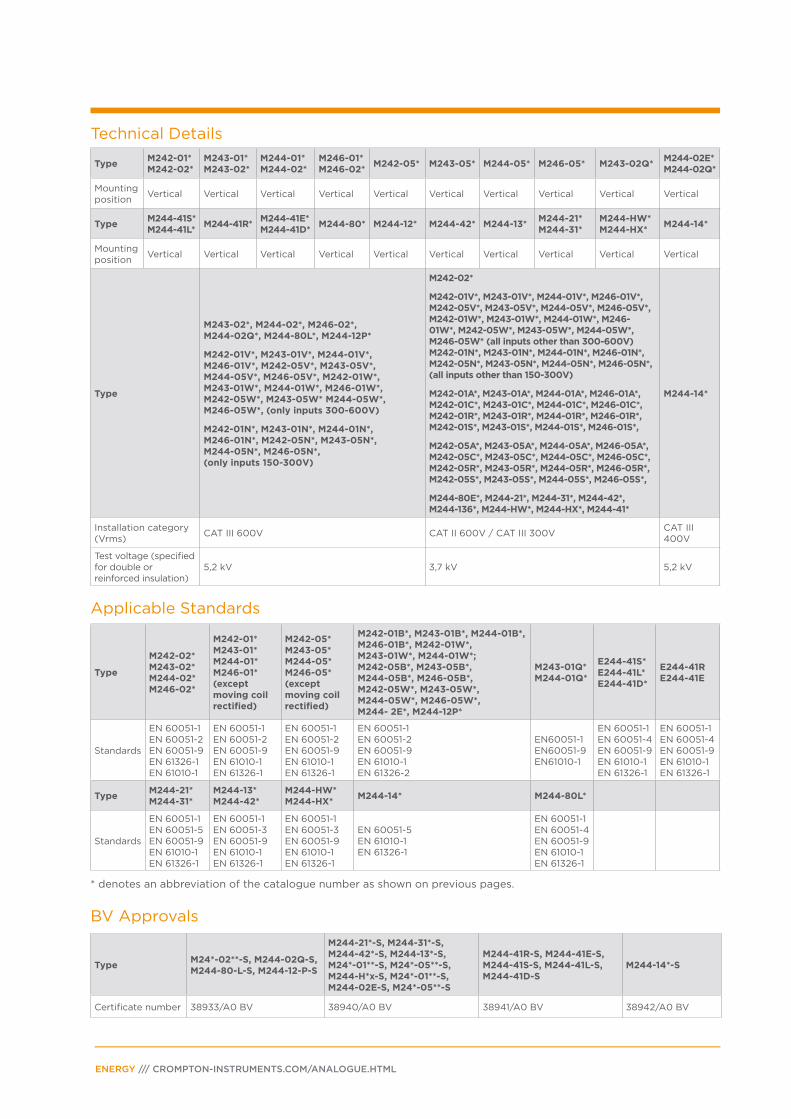
Technical Details
Applicable Standards
BV Approvals
TypeM242-01*M242-02*
M243-01*M243-02*
M244-01*M244-02*
M246-01*M246-02*
M242-05* M243-05* M244-05* M246-05* M243-02Q*M244-02E*M244-02Q*
Mountingposition
Vertical Vertical Vertical Vertical Vertical Vertical Vertical Vertical Vertical Vertical
TypeM244-41S*M244-41L*
M244-41R*M244-41E*M244-41D*
M244-80* M244-12* M244-42* M244-13*M244-21*M244-31*
M244-HW*M244-HX*
M244-14*
Mountingposition
Vertical Vertical Vertical Vertical Vertical Vertical Vertical Vertical Vertical Vertical
Type
M243-02*, M244-02*, M246-02*,M244-02Q*, M244-80L*, M244-12P*
M242-01V*, M243-01V*, M244-01V*,M246-01V*, M242-05V*, M243-05V*,M244-05V*, M246-05V*, M242-01W*,M243-01W*, M244-01W*, M246-01W*,M242-05W*, M243-05W* M244-05W*,M246-05W*, (only inputs 300-600V)
M242-01N*, M243-01N*, M244-01N*,M246-01N*, M242-05N*, M243-05N*,M244-05N*, M246-05N*,(only inputs 150-300V)
M242-02*
M242-01V*, M243-01V*, M244-01V*, M246-01V*,M242-05V*, M243-05V*, M244-05V*, M246-05V*,M242-01W*, M243-01W*, M244-01W*, M246-01W*, M242-05W*, M243-05W*, M244-05W*, M246-05W* (all inputs other than 300-600V)M242-01N*, M243-01N*, M244-01N*, M246-01N*,M242-05N*, M243-05N*, M244-05N*, M246-05N*,(all inputs other than 150-300V)
M242-01A*, M243-01A*, M244-01A*, M246-01A*,M242-01C*, M243-01C*, M244-01C*, M246-01C*,M242-01R*, M243-01R*, M244-01R*, M246-01R*,M242-01S*, M243-01S*, M244-01S*, M246-01S*,
M242-05A*, M243-05A*, M244-05A*, M246-05A*,M242-05C*, M243-05C*, M244-05C*, M246-05C*,M242-05R*, M243-05R*, M244-05R*, M246-05R*,M242-05S*, M243-05S*, M244-05S*, M246-05S*,
M244-80E*, M244-21*, M244-31*, M244-42*,M244-136*, M244-HW*, M244-HX*, M244-41*
M244-14*
Installation category(Vrms)
CAT III 600V CAT II 600V / CAT III 300VCAT III 400V
Test voltage (specifiedfor double or reinforced insulation)
5,2 kV 3,7 kV 5,2 kV
Type
M242-02*M243-02*M244-02*M246-02*
M242-01*M243-01*M244-01*M246-01*(except moving coil rectified)
M242-05*M243-05*M244-05*M246-05*(except moving coil rectified)
M242-01B*, M243-01B*, M244-01B*, M246-01B*, M242-01W*, M243-01W*, M244-01W*; M242-05B*, M243-05B*, M244-05B*, M246-05B*, M242-05W*, M243-05W*, M244-05W*, M246-05W*, M244- 2E*, M244-12P*
M243-01Q*M244-01Q*
E244-41S*E244-41L*E244-41D*
E244-41RE244-41E
Standards
EN 60051-1EN 60051-2EN 60051-9EN 61326-1EN 61010-1
EN 60051-1EN 60051-2EN 60051-9EN 61010-1EN 61326-1
EN 60051-1EN 60051-2EN 60051-9EN 61010-1EN 61326-1
EN 60051-1EN 60051-2EN 60051-9EN 61010-1EN 61326-2
EN60051-1EN60051-9EN61010-1
EN 60051-1EN 60051-4EN 60051-9EN 61010-1EN 61326-1
EN 60051-1EN 60051-4EN 60051-9EN 61010-1EN 61326-1
TypeM244-21*M244-31*
M244-13*M244-42*
M244-HW*M244-HX*
M244-14* M244-80L*
Standards
EN 60051-1EN 60051-5EN 60051-9EN 61010-1EN 61326-1
EN 60051-1EN 60051-3EN 60051-9EN 61010-1EN 61326-1
EN 60051-1EN 60051-3EN 60051-9EN 61010-1EN 61326-1
EN 60051-5EN 61010-1EN 61326-1
EN 60051-1EN 60051-4EN 60051-9EN 61010-1EN 61326-1
TypeM24*-02**-S, M244-02Q-S,M244-80-L-S, M244-12-P-S
M244-21*-S, M244-31*-S, M244-42*-S, M244-13*-S, M24*-01**-S, M24*-05**-S,M244-H*x-S, M24*-01**-S, M244-02E-S, M24*-05**-S
M244-41R-S, M244-41E-S,M244-41S-S, M244-41L-S,M244-41D-S
M244-14*-S
Certificate number 38933/A0 BV 38940/A0 BV 38941/A0 BV 38942/A0 BV
* denotes an abbreviation of the catalogue number as shown on previous pages.


ENERGY /// CROMPTON-INSTRUMENTS.COM/ANALOGUE.HTML
For email, phone or live chat, go to: crompton-instruments.com
FOR MORE INFORMATION: TE Technical Support Centres
About TE Connectivity
TE Connectivity (NYSE: TEL) is a $13 billion world leader in connectivity. The company designs
and manufactures products at the heart of electronic connections for the world’s leading
industries including automotive, energy and industrial, broadband communications, consumer
devices, healthcare, and aerospace and defense. TE Connectivity’s longstanding commitment to
innovation and engineering excellence helps its customers solve the need for more energy efficiency,
always-on communications and ever-increasing productivity. With nearly 90,000 employees in over
50 countries, TE Connectivity makes connections the world relies on to work flawlessly every day.
To connect with the company, visit: www.te.com.
• Mining
• Nuclear power plants
• OEMs
• Overhead distribution
• Petrochemical plants
• Railways
• Street lighting
• Substations
• Transmission lines
• Underground distribution
• Windfarms
• Solar
• Hydro-electric
WHEREVER ELECTRICITY FLOWS, YOU’LL FIND TE ENERGY
crompton-instruments.com
UK +44 1376 509 533
USA: +1-800-327-6996
Australia +61 1300-656-090
Singapore +65 6590 5151
Hong Kong: +852 - 2790 9609
te.com/energy© 2015 TE Connectivity Ltd. family of companies. All Rights Reserved. EPP-2410-10/15
TE Connectivity and the TE connectivity (logo) are trademarks of the TE Connectivity Ltd. family of companies. Crompton is a trademark of Crompton Parkinson and is used under a licence. Other logos, product and Company names mentioned herein may be trademarks of their respective owners. While TE has made every reasonable effort to ensure the accuracy of the information in this brochure, TE does not guarantee that it is error-free, nor does TE make any other representation, warranty or guarantee that the information is accurate, correct, reliable or current. TE reserves the right to make any adjustments to the information contained herein at any time without notice. TE expressly disclaims all implied warranties regarding the information contained herein, including, but not limited to, any implied warranties of merchantability or fitness for a particular purpose. The dimensions in this brochure are for reference purposes only and are subject to change without notice. Specifications are subject to change without notice. Consult TE for the latest dimensions and design specifications.