CROCKETT COGENERATION PROJECT (92-AFC-1C) · 23.01.2012 · • A Standard Operating Procedure...
10
CROCKETT COGENERATION PROJECT (92-AFC-1C) PETITION TO AMEND THE CALFORNIA ENERGY COMMISSION FINAL DECISION SUPPLEMENTAL DATA SUBMITTED JANUARY 12-20, 2012
Transcript of CROCKETT COGENERATION PROJECT (92-AFC-1C) · 23.01.2012 · • A Standard Operating Procedure...
CROCKETT COGENERATION PROJECT
(92-AFC-1C)
PETITION TO AMEND
THE CALFORNIA ENERGY COMMISSION
FINAL DECISION
SUPPLEMENTAL DATA
SUBMITTED JANUARY 12-20, 2012
CROCKETT COGENERATION PROJECT (92-AFC-1C) PETITION TO AMEND
SUPPLEMENTAL DATA 2 SUBMITTED JANUARY 12-20, 2012
Socioeconomics
Question 1: Will the proposed modifications require any additional operational workers to be hired? Answer: No additional personnel will be required to operate the fuel compression equipment. The fuel compression equipment will have sufficient automation so it can be controlled from the plant's Control Room. In addition, the current plant staffing includes a couple of outside operators that are continuously monitoring the equipment operation.
Visual Resources
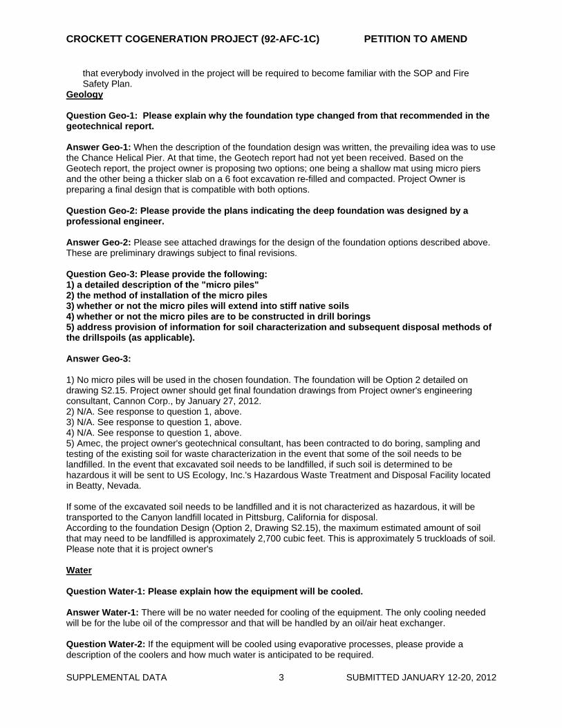
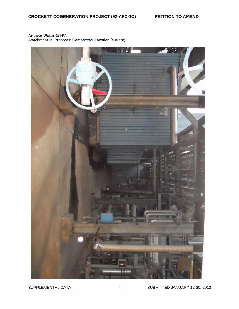
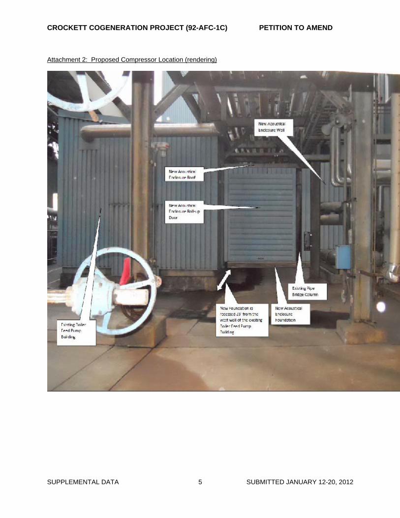
Question 1: Can you provide height information about the equipment and a conceptual elevation depicting how the equipment will fit in with the existing facilities where the equipment is proposed to be located? Answer : The height of the acoustical enclosure will be approximately 12 feet with a sloping roof.
I am attaching two files showing the compressor location before and after. As you can see, this spot is tucked in an area making views of it from a decent distance almost non-existent. This is the only decent location to shoot a photo and do a rendering from. This also demonstrates just how invisible the compression equipment will be to the outside world. It is dwarfed and surrounded by taller equipment/ structures.
See attachments 1 and 2: Proposed Compressor Location (current) and Proposed Compressor Location (rendering).
Hazardous Materials
Question 1: Can you provide a brief discussion of the applicability of NFPA 56PS: Standard for Fire and Explosion Prevention During Cleaning and Purging of Flammable Gas Piping Systems to the proposed project and if/how the project owner intends to comply with the Provisional Standard? Answer: NFPA 56PS is applicable to this project in the sense that the project involves cutting and welding onto the natural gas pipeline that feeds the fuel to the gas turbine. In that context, NFPA 56PS is applicable to the purging of the line before it is worked on and after the work is completed as it will required to be blown down to make sure that the line is free from debris before the gas can be re-introduced into the gas turbine. Crockett is insuring compliance with NFPA56PS by: • Crockett will utilize a mechanical contractor that is intimately familiar and experienced with
NFPA 56PS and the applicable processes of emptying and purging gas pipelines before and after cutting and welding activities take place. The contractor will utilize pipefitters and code welders that are familiar with the requirements of NFPA 56PS.
• All purging and gas blowing will be accomplished by using oil-free air compressors. • A safety coordinator who is also intimately familiar with NFPA 56PS will be on site coordinating these
activities. • A Standard Operating Procedure (SOP) will be produced for these particular parts of the
project. This SOP will incorporate the requirements from NFPA 56PS as well as other codes and standards and will be part of the Fire Safety Plan to be reviewed and approved by the Contra Costa County Fire Department Fire Chief in the City of Crockett.
• As part of the Daily Safety Briefing we will hold a Contractor Safety Orientation that will insure
CROCKETT COGENERATION PROJECT (92-AFC-1C) PETITION TO AMEND
SUPPLEMENTAL DATA 3 SUBMITTED JANUARY 12-20, 2012
that everybody involved in the project will be required to become familiar with the SOP and Fire Safety Plan.
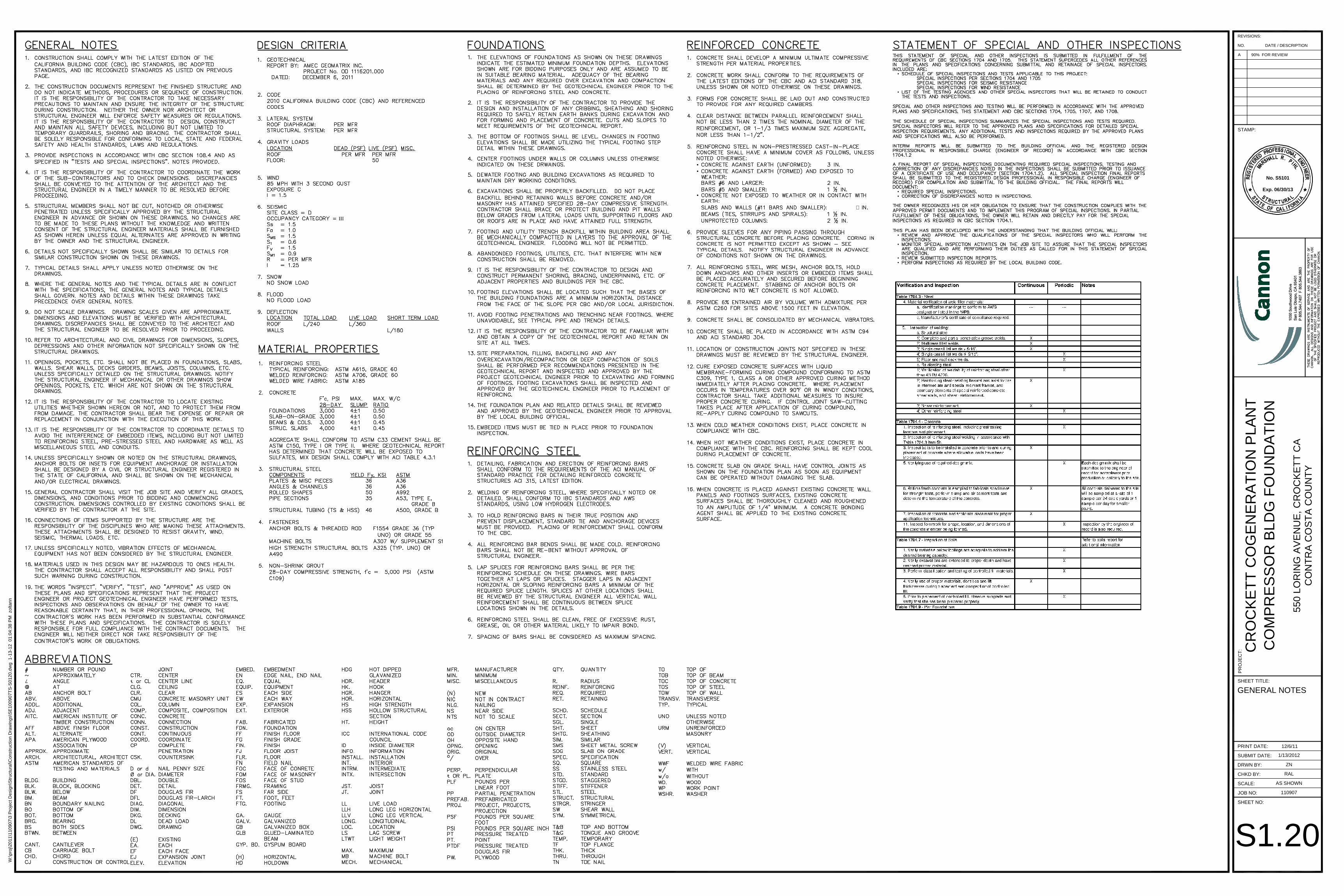
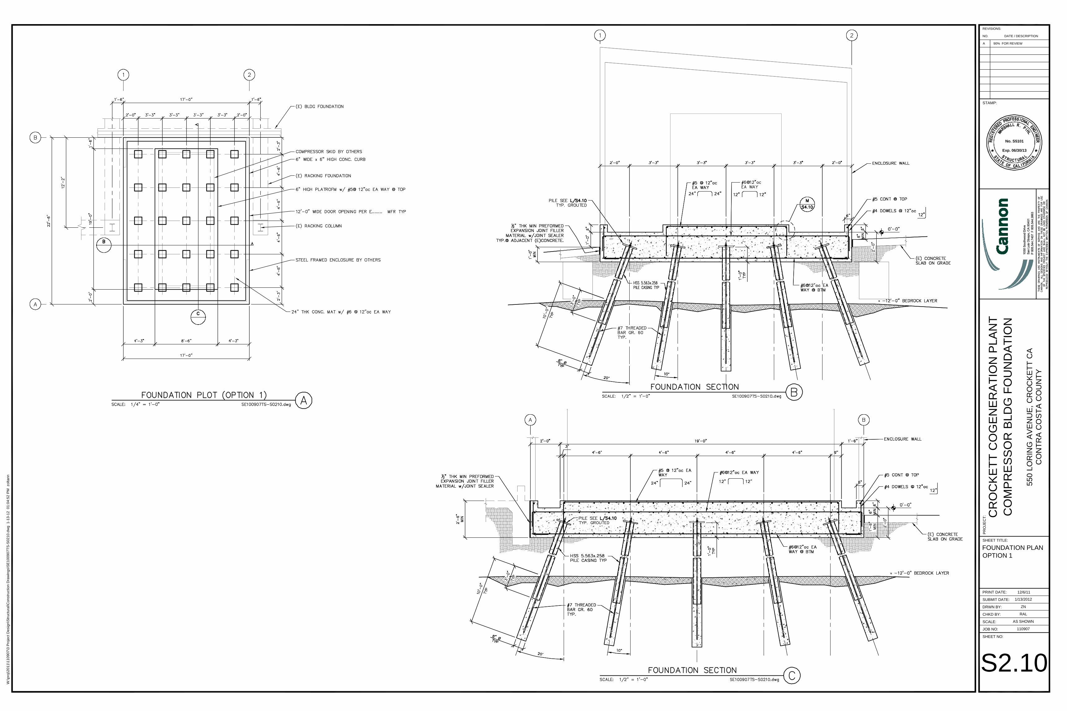
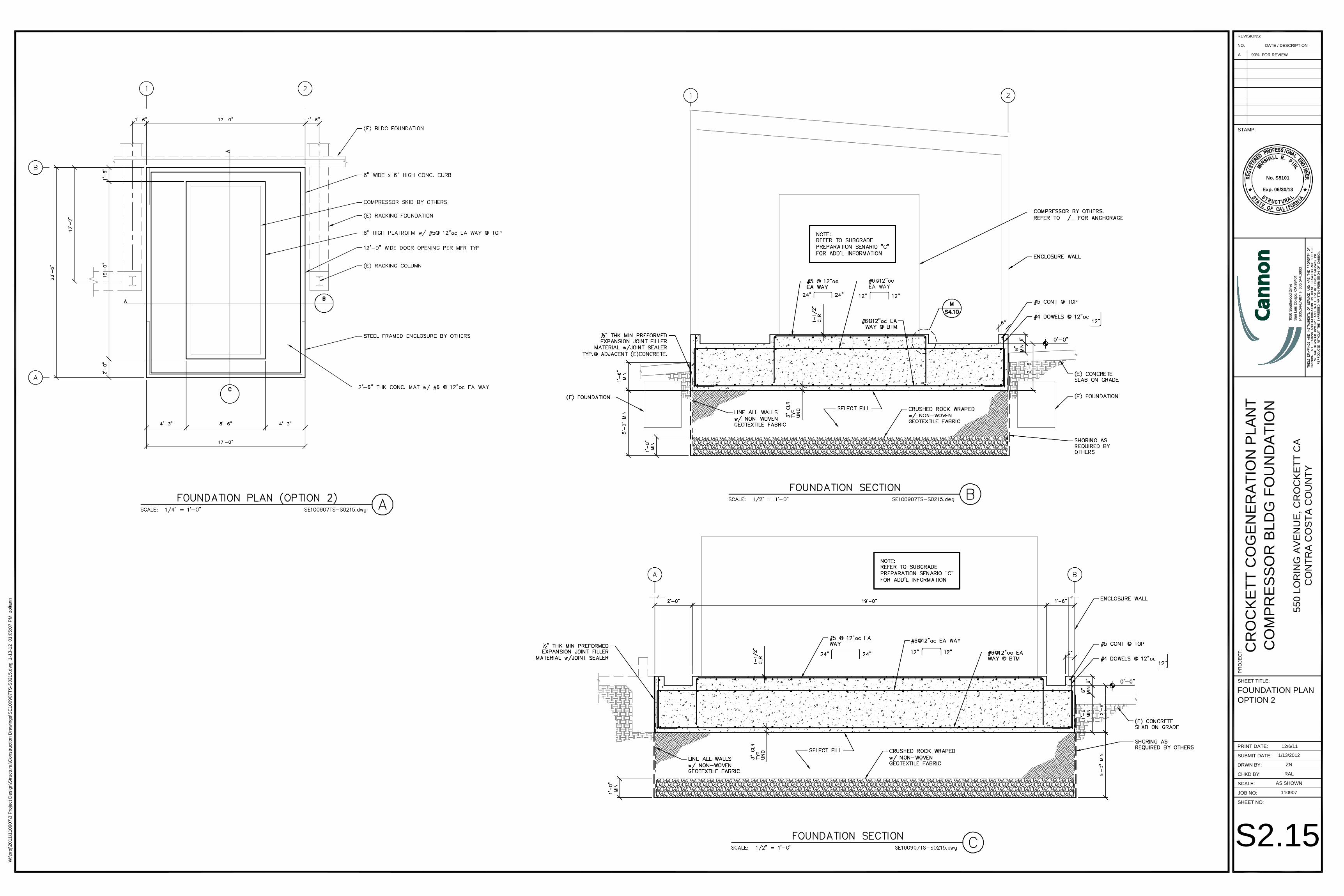
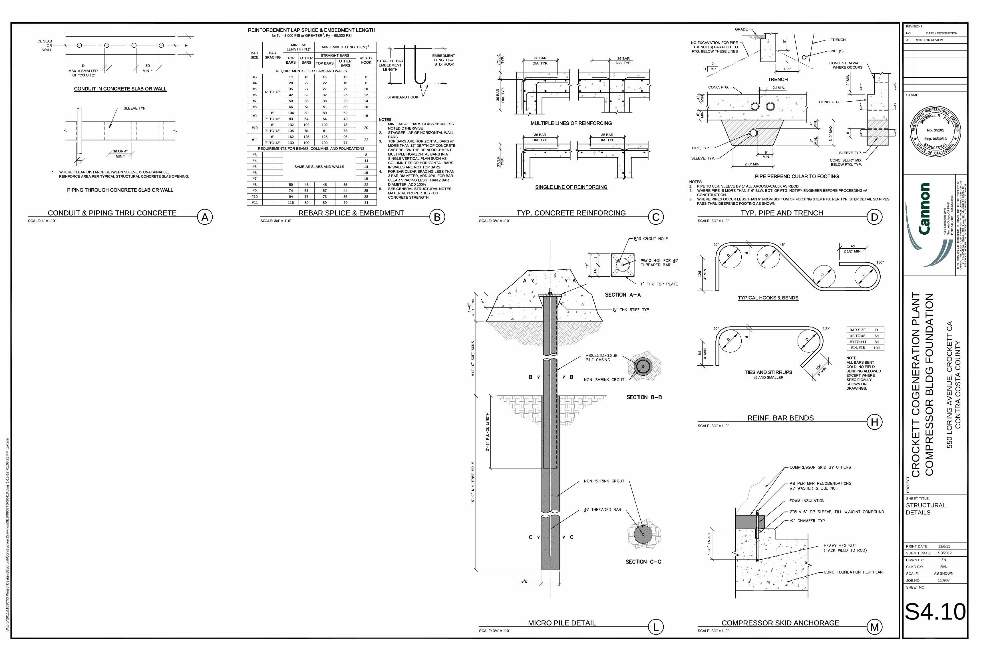
Geology Question Geo-1: Please explain why the foundation type changed from that recommended in the geotechnical report. Answer Geo-1: When the description of the foundation design was written, the prevailing idea was to use the Chance Helical Pier. At that time, the Geotech report had not yet been received. Based on the Geotech report, the project owner is proposing two options; one being a shallow mat using micro piers and the other being a thicker slab on a 6 foot excavation re-filled and compacted. Project Owner is preparing a final design that is compatible with both options. Question Geo-2: Please provide the plans indicating the deep foundation was designed by a professional engineer. Answer Geo-2: Please see attached drawings for the design of the foundation options described above. These are preliminary drawings subject to final revisions. Question Geo-3: Please provide the following: 1) a detailed description of the "micro piles" 2) the method of installation of the micro piles 3) whether or not the micro piles will extend into stiff native soils 4) whether or not the micro piles are to be constructed in drill borings 5) address provision of information for soil characterization and subsequent disposal methods of the drillspoils (as applicable). Answer Geo-3: 1) No micro piles will be used in the chosen foundation. The foundation will be Option 2 detailed on drawing S2.15. Project owner should get final foundation drawings from Project owner's engineering consultant, Cannon Corp., by January 27, 2012. 2) N/A. See response to question 1, above. 3) N/A. See response to question 1, above. 4) N/A. See response to question 1, above. 5) Amec, the project owner's geotechnical consultant, has been contracted to do boring, sampling and testing of the existing soil for waste characterization in the event that some of the soil needs to be landfilled. In the event that excavated soil needs to be landfilled, if such soil is determined to be hazardous it will be sent to US Ecology, Inc.'s Hazardous Waste Treatment and Disposal Facility located in Beatty, Nevada. If some of the excavated soil needs to be landfilled and it is not characterized as hazardous, it will be transported to the Canyon landfill located in Pittsburg, California for disposal. According to the foundation Design (Option 2, Drawing S2.15), the maximum estimated amount of soil that may need to be landfilled is approximately 2,700 cubic feet. This is approximately 5 truckloads of soil. Please note that it is project owner's Water Question Water-1: Please explain how the equipment will be cooled. Answer Water-1: There will be no water needed for cooling of the equipment. The only cooling needed will be for the lube oil of the compressor and that will be handled by an oil/air heat exchanger. Question Water-2: If the equipment will be cooled using evaporative processes, please provide a description of the coolers and how much water is anticipated to be required.
CROCKETT COGENERATION PROJECT (92-AFC-1C) PETITION TO AMEND
SUPPLEMENTAL DATA 4 SUBMITTED JANUARY 12-20, 2012
Answer Water-2: N/A. Attachment 1: Proposed Compressor Location (current)
CROCKETT COGENERATION PROJECT (92-AFC-1C) PETITION TO AMEND
SUPPLEMENTAL DATA 5 SUBMITTED JANUARY 12-20, 2012
Attachment 2: Proposed Compressor Location (rendering)
CROCKETT COGENERATION PROJECT (92-AFC-1C) PETITION TO AMEND
SUPPLEMENTAL DATA 6 SUBMITTED JANUARY 12-20, 2012
Attachment 3: Compressor Building Foundation Plan Options and Structural Details (subject to final revisions)
••
•
∠ ℄
�
•
•
••
•
•
••
III
SUBMIT DATE:
DRWN BY:
CHKD BY:
SCALE:
JOB NO:
SHEET NO:
REVISIONS:
NO. DATE / DESCRIPTION
STAMP:
SHEET TITLE:
PR
OJE
CT
:
PRINT DATE: 12/6/11
CR
OC
KE
TT
CO
GE
NE
RA
TIO
N P
LAN
TC
OM
PR
ES
SO
R B
LDG
FO
UN
DA
TIO
N
550
LOR
ING
AV
EN
UE
, CR
OC
KE
TT
CA
CO
NT
RA
CO
ST
A C
OU
NT
Y
1/13/2012
ZN
RAL
AS SHOWN
110907
No. S5101
Exp. 06/30/13
A 90% FOR REVIEW
W:\p
roj\2
011\
1109
07\3
Pro
ject
Des
ign\
Str
uctu
ral\C
onst
ruct
ion
Dra
win
gs\S
E10
0907
TS
-S01
20.d
wg
1-1
3-12
01:
04:3
8 P
M z
olta
nn
GENERAL NOTES
S1.20
≈≈
≈≈
SUBMIT DATE:
DRWN BY:
CHKD BY:
SCALE:
JOB NO:
SHEET NO:
REVISIONS:
NO. DATE / DESCRIPTION
STAMP:
SHEET TITLE:
PR
OJE
CT
:
PRINT DATE: 12/6/11
CR
OC
KE
TT
CO
GE
NE
RA
TIO
N P
LAN
TC
OM
PR
ES
SO
R B
LDG
FO
UN
DA
TIO
N
550
LOR
ING
AV
EN
UE
, CR
OC
KE
TT
CA
CO
NT
RA
CO
ST
A C
OU
NT
Y
1/13/2012
ZN
RAL
AS SHOWN
110907
No. S5101
Exp. 06/30/13
A 90% FOR REVIEW
W:\p
roj\2
011\
1109
07\3
Pro
ject
Des
ign\
Str
uctu
ral\C
onst
ruct
ion
Dra
win
gs\S
E10
0907
TS
-S02
10.d
wg
1-1
3-12
01:
04:5
2 P
M z
olta
nn
FOUNDATION PLANOPTION 1
S2.10
SUBMIT DATE:
DRWN BY:
CHKD BY:
SCALE:
JOB NO:
SHEET NO:
REVISIONS:
NO. DATE / DESCRIPTION
STAMP:
SHEET TITLE:
PR
OJE
CT
:
PRINT DATE: 12/6/11
CR
OC
KE
TT
CO
GE
NE
RA
TIO
N P
LAN
TC
OM
PR
ES
SO
R B
LDG
FO
UN
DA
TIO
N
550
LOR
ING
AV
EN
UE
, CR
OC
KE
TT
CA
CO
NT
RA
CO
ST
A C
OU
NT
Y
1/13/2012
ZN
RAL
AS SHOWN
110907
No. S5101
Exp. 06/30/13
A 90% FOR REVIEW
W:\p
roj\2
011\
1109
07\3
Pro
ject
Des
ign\
Str
uctu
ral\C
onst
ruct
ion
Dra
win
gs\S
E10
0907
TS
-S02
15.d
wg
1-1
3-12
01:
05:0
7 P
M z
olta
nn
FOUNDATION PLANOPTION 2
S2.15
H
M
TYPICAL HOOKS & BENDS
90° 45°
BAR SIZE D
#3 TO #8 6d
#9 TO #11 8d
#14, #18 10d
4d
2 1/2" MIN.
180°
DD
D
d
D
12d
4" M
IN.
D D
90° 135°
6d
4" M
IN.
d
#5 AND SMALLER
10d
5" M
IN.
ALL BARS BENTCOLD. NO FIELDBENDING ALLOWEDEXCEPT WHERESPECIFICALLYSHOWN ONDRAWINGS.
REINF. BAR BENDS
SCALE: 3/4" = 1'-0"
COMPRESSOR SKID ANCHORAGE
SCALE: 3/4" = 1'-0"
A
D
MAX. = SMALLER OF "t"/3 OR 2"
3D
MIN. *
"t"
CL SLABOR
WALL
* WHERE CLEAR DISTANCE BETWEEN SLEEVE IS UNATAINABLE,REINFORCE AREA PER TYPICAL STRUCTURAL CONCRETE SLAB OPENING.
3d OR 4"
MIN.*d
SLEEVE TYP.
CONDUIT & PIPING THRU CONCRETE
SCALE: 1" = 1'-0" A
D
MAX. = SMALLER OF "t"/3 OR 2"
3D
MIN. *
"t"
CL SLABOR
WALL
* WHERE CLEAR DISTANCE BETWEEN SLEEVE IS UNATAINABLE,REINFORCE AREA PER TYPICAL STRUCTURAL CONCRETE SLAB OPENING.
3d OR 4"
MIN.*d
SLEEVE TYP.
CONDUIT & PIPING THRU CONCRETE
SCALE: 1" = 1'-0" B C D
for f'c = 3,000 PSI or GREATER5, Fy = 60,000 PSI
BARSIZE
BARSPACING
MIN. LAPLENGTH (IN.)4 MIN. EMBED. LENGTH (IN.)4
TOPBARS
OTHERBARS
STRAIGHT BARSw/ STD.HOOKTOP BARS
OTHERBARS
REQUIREMENTS FOR SLABS AND WALLS
#3
6" TO 12"
21 16 16 12 6
#4 28 22 22 16 8
#5 35 27 27 21 10
#6 42 32 32 25 12
#7 50 38 38 29 14
#8 66 51 51 39 16
#96" 104 80 80 62
187" TO 12" 83 64 64 49
#106" 132 102 102 78
207" TO 12" 106 81 81 63
#116" 162 125 125 96
227" TO 12" 130 100 100 77
REQUIREMENTS FOR BEAMS, COLUMNS, AND FOUNDATIONS
#3 -
SAME AS SLABS AND WALLS
8
#4 - 11
#5 - 14
#6 - 16
#7 - 19
#8 - 59 45 45 35 22
#9 - 74 57 57 44 25
#10 - 94 73 73 56 28
#11 - 116 89 89 69 31
1. MIN. LAP ALL BARS CLASS 'B' UNLESSNOTED OTHERWISE
2. STAGGER LAP OF HORIZONTAL WALLBARS
3. TOP BARS ARE HORIZONTAL BARS w/MORE THAN 12" DEPTH OF CONCRETECAST BELOW THE REINFORCEMENT.MULTIPLE HORIZONTAL BARS IN ASINGLE VERTICAL PLAN SUCH ASCOLUMN TIES OR HORIZONTAL BARSIN WALLS ARE NOT TOP BARS
4. FOR BAR CLEAR SPACING LESS THAN3 BAR DIAMETER, ADD 40%. FOR BARCLEAR SPACING LESS THAN 2 BARDIAMETER, ADD 100%
5. SEE GENERAL STRUCTURAL NOTES,MATERIAL PROPERTIES FORCONCRETE STRENGTH
STRAIGHT BAREMBEDMENT
LENGTH
EMBEDMENTLENGTH w/ STD. HOOK
REBAR SPLICE & EMBEDMENT
SCALE: 3/4" = 1'-0"
STANDARD HOOK
1. PIPE TO CLR. SLEEVE BY 1" ALL AROUND-CAULK AS REQD.2. WHERE PIPE IS MORE THAN 2'-6" BLW. BOT. OF FTG. NOTIFY ENGINEER BEFORE PROCEEDING w/
CONSTRUCTION.3. WHERE PIPES OCCUR LESS THAN 6" FROM BOTTOM OF FOOTING STEP FTG. PER TYP. STEP DETAIL SO PIPES
PASS THRU DEEPENED FOOTING AS SHOWN
1'-6"
9"MIN.
2'-0" MIN.
4"M
IN.
6"M
IN.
3"M
IN.
4"M
IN.
3'-0
" M
AX
.
2d MIN.
2" M
IN.
d
9"
1
2
TYP
TYP. PIPE AND TRENCH
SCALE: 3/4" = 1'-0"
NO EXCAVATION FOR PIPETRENCH(S) PARALLEL TO
FTG. BELOW THESE LINES
GRADE
PIPE(S)
TRENCH
CONC. STEM WALLWHERE OCCURS
CONC. FTG.
SLEEVE TYP.
CONC. SLURY MIXBELOW FTG. TYP.
SLEEVE, TYP.
PIPE, TYP.
CONC. FTG.
36 BARDIA. TYP.
36 BAR
DIA. TYP.
3"C
LR.
TY
P.
36 B
AR
DIA
. TY
P.
3"C
LR.
TY
P.
36 BAR
DIA. TYP.
36 BAR
DIA. TYP.
TYP. CONCRETE REINFORCING
SCALE: 3/4" = 1'-0"B C D
for f'c = 3,000 PSI or GREATER5, Fy = 60,000 PSI
BARSIZE
BARSPACING
MIN. LAPLENGTH (IN.)4 MIN. EMBED. LENGTH (IN.)4
TOPBARS
OTHERBARS
STRAIGHT BARSw/ STD.HOOKTOP BARS
OTHERBARS
REQUIREMENTS FOR SLABS AND WALLS
#3
6" TO 12"
21 16 16 12 6
#4 28 22 22 16 8
#5 35 27 27 21 10
#6 42 32 32 25 12
#7 50 38 38 29 14
#8 66 51 51 39 16
#96" 104 80 80 62
187" TO 12" 83 64 64 49
#106" 132 102 102 78
207" TO 12" 106 81 81 63
#116" 162 125 125 96
227" TO 12" 130 100 100 77
REQUIREMENTS FOR BEAMS, COLUMNS, AND FOUNDATIONS
#3 -
SAME AS SLABS AND WALLS
8
#4 - 11
#5 - 14
#6 - 16
#7 - 19
#8 - 59 45 45 35 22
#9 - 74 57 57 44 25
#10 - 94 73 73 56 28
#11 - 116 89 89 69 31
1. MIN. LAP ALL BARS CLASS 'B' UNLESSNOTED OTHERWISE
2. STAGGER LAP OF HORIZONTAL WALLBARS
3. TOP BARS ARE HORIZONTAL BARS w/MORE THAN 12" DEPTH OF CONCRETECAST BELOW THE REINFORCEMENT.MULTIPLE HORIZONTAL BARS IN ASINGLE VERTICAL PLAN SUCH ASCOLUMN TIES OR HORIZONTAL BARSIN WALLS ARE NOT TOP BARS
4. FOR BAR CLEAR SPACING LESS THAN3 BAR DIAMETER, ADD 40%. FOR BARCLEAR SPACING LESS THAN 2 BARDIAMETER, ADD 100%
5. SEE GENERAL STRUCTURAL NOTES,MATERIAL PROPERTIES FORCONCRETE STRENGTH
STRAIGHT BAREMBEDMENT
LENGTH
EMBEDMENTLENGTH w/ STD. HOOK
REBAR SPLICE & EMBEDMENT
SCALE: 3/4" = 1'-0"
STANDARD HOOK
1. PIPE TO CLR. SLEEVE BY 1" ALL AROUND-CAULK AS REQD.2. WHERE PIPE IS MORE THAN 2'-6" BLW. BOT. OF FTG. NOTIFY ENGINEER BEFORE PROCEEDING w/
CONSTRUCTION.3. WHERE PIPES OCCUR LESS THAN 6" FROM BOTTOM OF FOOTING STEP FTG. PER TYP. STEP DETAIL SO PIPES
PASS THRU DEEPENED FOOTING AS SHOWN
1'-6"
9"MIN.
2'-0" MIN.
4"M
IN.
6"M
IN.
3"M
IN.
4"M
IN.
3'-0
" M
AX
.
2d MIN.
2" M
IN.
d
9"
1
2
TYP
TYP. PIPE AND TRENCH
SCALE: 3/4" = 1'-0"
NO EXCAVATION FOR PIPETRENCH(S) PARALLEL TO
FTG. BELOW THESE LINES
GRADE
PIPE(S)
TRENCH
CONC. STEM WALLWHERE OCCURS
CONC. FTG.
SLEEVE TYP.
CONC. SLURY MIXBELOW FTG. TYP.
SLEEVE, TYP.
PIPE, TYP.
CONC. FTG.
36 BARDIA. TYP.
36 BAR
DIA. TYP.
3"C
LR.
TY
P.
36 B
AR
DIA
. TY
P.
3"C
LR.
TY
P.
36 BAR
DIA. TYP.
36 BAR
DIA. TYP.
TYP. CONCRETE REINFORCING
SCALE: 3/4" = 1'-0"
LMICRO PILE DETAIL
SCALE: 3/4" = 1'-0" LMICRO PILE DETAIL
SCALE: 3/4" = 1'-0"
SUBMIT DATE:
DRWN BY:
CHKD BY:
SCALE:
JOB NO:
SHEET NO:
REVISIONS:
NO. DATE / DESCRIPTION
STAMP:
SHEET TITLE:
PR
OJE
CT
:
PRINT DATE: 12/6/11
CR
OC
KE
TT
CO
GE
NE
RA
TIO
N P
LAN
TC
OM
PR
ES
SO
R B
LDG
FO
UN
DA
TIO
N
550
LOR
ING
AV
EN
UE
, CR
OC
KE
TT
CA
CO
NT
RA
CO
ST
A C
OU
NT
Y
1/13/2012
ZN
RAL
AS SHOWN
110907
No. S5101
Exp. 06/30/13
A 90% FOR REVIEW
W:\p
roj\2
011\
1109
07\3
Pro
ject
Des
ign\
Str
uctu
ral\C
onst
ruct
ion
Dra
win
gs\S
E10
0907
TS
-S04
10.d
wg
1-1
3-12
01:
05:2
3 P
M z
olta
nn
STRUCTURALDETAILS
S4.10