Critical Heat Flux in Subcooled Flow Boiling of Water · Flow boiling has an extremely high heat...
26
Chapter 9 © 2012 Chen, licensee InTech. This is an open access chapter distributed under the terms of the Creative Commons Attribution License (http://creativecommons.org/licenses/by/3.0), which permits unrestricted use, distribution, and reproduction in any medium, provided the original work is properly cited. Critical Heat Flux in Subcooled Flow Boiling of Water Yuzhou Chen Additional information is available at the end of the chapter http://dx.doi.org/10.5772/52307 1. Introduction Flow boiling has an extremely high heat transfer coefficient, and is applied in variety of practices. However, once the heat flux exceeds a certain high level the heated surface can no longer support continuous liquid contact, associated with substantial reduction in the heat transfer efficiency. It may result in a sudden rise of surface temperature in a heat flux controlled system, or a drastic decrease in power transferred in a temperature controlled system. This phenomenon is called the boiling crisis, and the maximum heat flux just before the boiling crisis is usually referred to as critical heat flux (CHF). Depending on the flow regimes, two types of CHF are classified: (i) in subcooled or low quality region the CHF is characterized by the transition from nucleate boiling to film boiling, and it is termed as the departure from nucleate boiling (DNB); (ii) in higher quality region the CHF is characterized by the dryout of liquid film of annular flow. The DNB and dryout have substantially different mechanisms, and are generally cataloged as the first and the second kind of critical heat flux, respectively (Tong and Tang, 1997). The CHF is an important subject to many engineering applications. Especially, in a nuclear reactor the occurrence of critical heat flux could lead to a failure of fuel element, and thus the CHF is a major limit for the reactor safety. During past five decades the CHF has been investigated extensively over the world theoretically and experimentally (IAEA-TECDOC- 1203, 2001). A great number of empirical correlations and physical models have been proposed. In recent years, a Look-Up Table method (LUT) is widely accepted due to its advantages of higher accuracy, wider range of application, correct asymptotic trend and convenience for updating (Groeneveld, et al., 1996). This table is applied in the system code RELAP5 for reactor safety analysis. The LUT contains a tabulation of normalized CHF data of a uniformly heated tube of 8 mm in diameter at discrete local parameters of pressure, mass flux and quality. Several correction factors are incorporated for utilization of the LUT
Transcript of Critical Heat Flux in Subcooled Flow Boiling of Water · Flow boiling has an extremely high heat...

Chapter 9
© 2012 Chen, licensee InTech. This is an open access chapter distributed under the terms of the Creative Commons Attribution License (http://creativecommons.org/licenses/by/3.0), which permits unrestricted use, distribution, and reproduction in any medium, provided the original work is properly cited.
Critical Heat Flux in Subcooled Flow Boiling of Water
Yuzhou Chen
Additional information is available at the end of the chapter
http://dx.doi.org/10.5772/52307
1. Introduction
Flow boiling has an extremely high heat transfer coefficient, and is applied in variety of practices. However, once the heat flux exceeds a certain high level the heated surface can no longer support continuous liquid contact, associated with substantial reduction in the heat transfer efficiency. It may result in a sudden rise of surface temperature in a heat flux controlled system, or a drastic decrease in power transferred in a temperature controlled system. This phenomenon is called the boiling crisis, and the maximum heat flux just before the boiling crisis is usually referred to as critical heat flux (CHF).
Depending on the flow regimes, two types of CHF are classified: (i) in subcooled or low quality region the CHF is characterized by the transition from nucleate boiling to film boiling, and it is termed as the departure from nucleate boiling (DNB); (ii) in higher quality region the CHF is characterized by the dryout of liquid film of annular flow. The DNB and dryout have substantially different mechanisms, and are generally cataloged as the first and the second kind of critical heat flux, respectively (Tong and Tang, 1997).
The CHF is an important subject to many engineering applications. Especially, in a nuclear reactor the occurrence of critical heat flux could lead to a failure of fuel element, and thus the CHF is a major limit for the reactor safety. During past five decades the CHF has been investigated extensively over the world theoretically and experimentally (IAEA-TECDOC-1203, 2001). A great number of empirical correlations and physical models have been proposed. In recent years, a Look-Up Table method (LUT) is widely accepted due to its advantages of higher accuracy, wider range of application, correct asymptotic trend and convenience for updating (Groeneveld, et al., 1996). This table is applied in the system code RELAP5 for reactor safety analysis. The LUT contains a tabulation of normalized CHF data of a uniformly heated tube of 8 mm in diameter at discrete local parameters of pressure, mass flux and quality. Several correction factors are incorporated for utilization of the LUT

An Overview of Heat Transfer Phenomena 194
in other conditions to account for the effects of diameter, bundle, spacer, flux distribution, flow orientation, etc.. Unfortunately, there exists a scarcity of CHF data in low pressure/low flow/ subcooled region, as shown in Fig.1. Because of the extreme complexity of the phenomenon and the lack of adequate knowledge of the mechanisms, all these predictive methods are heavily relied on experimental data, and can not be extrapolated out of their ranges with confidence.
In China Institute of Atomic Energy (CIAE), in the past four decades a great number of CHF experimental data of subcooled boiling of flowing water were obtained in tubes and annuli at lower pressure with different diameter or gap to support the designs of research reactors, HFR and CARR, which were first put into operation in 1980 and 2011, respectively. In recent years the experiments were extended to the region of near-critical pressure with lower flow for the R&D of Supercritical Water-Cooled Reactor (SCWR). In these experiments the CHF (DNB) phenomena are studied with emphases on lower pressure and higher pressure with lower flow. The characteristics and parametric trends of the CHF are clarified, and the physical models are derived.
Figure 1. Range of database for 1996 CHF Look-up table (Groeneveld, et al., 1996)
2. Parametric trends A comprehensive review on the subcooled flow boiling CHF was given by Berglest (1977). As concluded, the effect of heating length disappears when exceeding 200 mm and the subcooled boiling CHF depends only on local parameter (“local condition hypothesis”). The CHF increases with the local mass flux and subcooling increasing. The effect of pressure is more complicated: the CHF increases with pressure in low pressure region, is relatively constant over an intermediate range of pressure, and decreases in high pressure region. The effect of geometry on CHF is observed in many experiments, and is accounted by a factor f = (De/8)n, in which De is the hydraulic diameter in mm. Different value of the exponent n is obtained from different experiments, ranging from -0.1 to -0.5. For applying the LUT in reactor safety analysis code RELAP5 the value of n = -0.5 is used. While for annulus or rectangular channels the effect of gap width is not observed in many experiments.
In Savannah River lab and Columbia University the subcooled CHF experiments were conducted with D2O and H2O coolant and aluminum and stainless-steel heaters (Knoebel et al., 1973). It was concluded that the CHF for D2O is 16% greater than for H2O at constant subcooling and velocity, and the CHF of aluminum heaters is a minimum of 20% greater than for stainless steel.

Critical Heat Flux in Subcooled Flow Boiling of Water 195
Some typical subcooled boiling CHF correlations are listed in Tab.1. Similar trends of the CHF with the flow rate and subcooling are represented in various correlations, but the degrees of these effects are different significantly. The present investigation has revealed that these effects are inter-dependent, associated with complicated parametrical trends for different regions of conditions.
Table 1. Subcooled flow boiling CHF correlations

An Overview of Heat Transfer Phenomena 196
3. Experiment
3.1. Technique
The onset of critical heat flux is characterized by a drastic increase in the wall temperature. For subcooled flow boiling of water with lower pressure the critical heat flux is higher and it could lead to a failure of the heated wall rapidly. This kind of CHF is also called as “fast burnout”. In experiment the onset of CHF is usually detected by thermocouples for protection of the test section. However, the occurrence of CHF generally initiates from a small area (or a spot), and for a test section of larger size the CHF spot can not be expected exactly. This presents a challenge for prevention of the test section from burnout. For this condition the photocell has advantage for the detection of CHF.
In the present experiments the pressure and flow rate are kept at constant, and the CHF is approached by increasing slowly the water temperature or the power to test section. When the CHF occurs and the wall temperature exceeds about 500°C, the photocell produces an output, which switches off the power supply to test section. This technique is used by author for all the experiments in tubes and annuli.
3.2. Experimental results
3.2.1. Higher pressure CHF (Chen et al., 2011)
Experiment was performed in an uniformly heated inconel tube of 7.95 mm in diameter and 0.8 m in heating length, covering the ranges of pressure of p = 1.96 – 20.4 MPa, mass flux of G = 476 – 1653 kg/m2s, inlet subcooling of ,s iT = 49 – 343 K, outlet subcooling of ,s oT = 1 –
145 K and critical heat flux of Cq = 0.26 – 4.95 MW/m2.
For the present low flow condition the CHF is related to the inlet condition, characterizing the mechanism of total power dominant. Totally, 193 data are obtained, and are formulated as the following empiric correlation,
C sq cq
where sq is the heat flux for the exit to reach the saturation temperature, evaluated by
( )
4s i
sH H GD
qL
(1)
and
0.352350(1 0.0307 )( ( )) ,1.0s ic Min p G H H
where p is the pressure, iH and sH the inlet enthalpy and saturation enthalpy, respectively, G the mass flux, D the diameter and L the heating length. Fig.2 shows the

Critical Heat Flux in Subcooled Flow Boiling of Water 197
comparison of the prediction of Eq.(1) with the experimental data by plotting the ratio of qCHF,c/qCHF,M versus P or G. The average deviation, AVG, is 0.75% and the standard deviation, RMS, is 5.34%.
Figure 2. Comparison of experimental data of higher pressure with the prediction by Eq.(1)
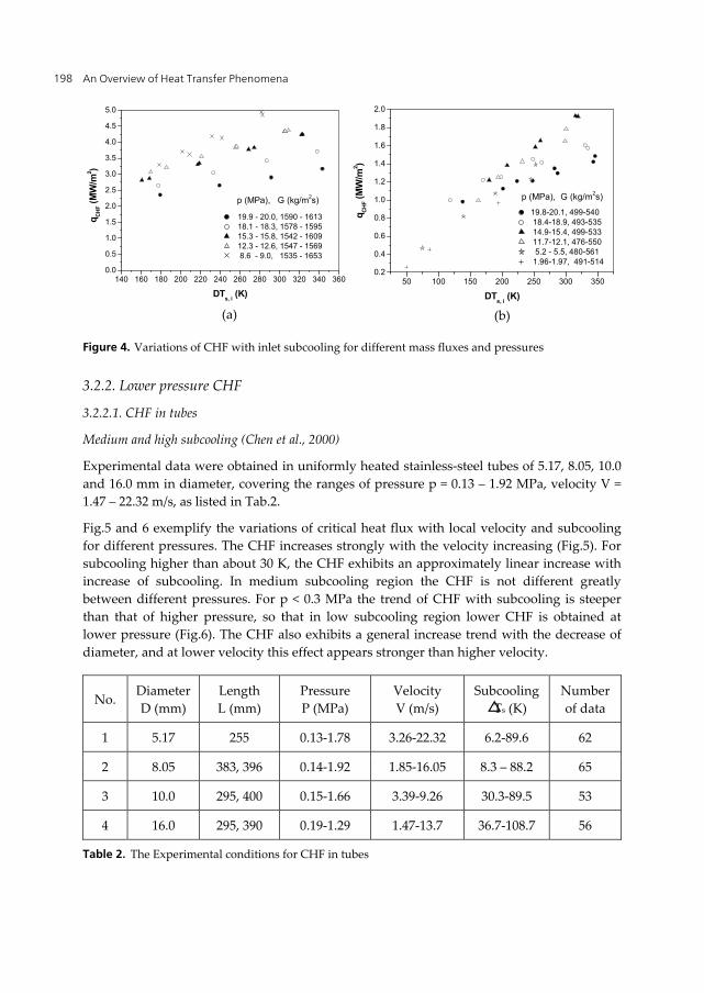
The effects of mass flux, inlet subcooling and pressure are exemplified in Fig.3 and 4. The CHF decreases substantially with mass flux decreasing. As can be seen, at G > 1200 kg/m2s the data are close to the prediction of 96-CHF Look-Up Table (LUT), but at low mass flux the data are overpredicted significantly (Fig.3). For lower pressure the effects of inlet subcooling and mass flux are stronger than higher pressure, associated with complicated trend of the CHF with pressure. For G > 1200 kg/m2s higher CHF corresponds to lower pressure, especially in high subcooling region (Fig.4(a)). For G= 700 – 1200 kg/m2s the results of p < 16 MPa are not different appreciably for different pressures. For G< 600 kg/m2s, in high subcooling region lower CHF corresponds to higher pressure, while in low subcooling region lower CHF is attained at lower pressure (Fig.4 (b))
Figure 3. Effect of mass flux on the CHF
0 200 400 600 800 1000120014001600180020002200
1000000
2000000
3000000
4000000
5000000
6000000
p = 10 MPa
qC
HF
(W/m
2 )
G (kg/m2s)
data x = - 0.038 - - 0.12 LUT x = - 0.05
0 5 10 15 200.5
0.6
0.7
0.8
0.9
1.0
1.1
1.2
DTs, i
= 49 - 346 KG = 476 - 1653 kg/m2sp = 1.96 - 20.4 MPa
RMS = 5.34%AVG = 0.75%
R =
qC
HF
, C/ q
CH
F, M
p (MPa)
400 600 800 1000 1200 1400 1600 18000.5
0.6
0.7
0.8
0.9
1.0
1.1
1.2
DTs, i
= 49 - 346 KG = 476 - 1653 kg/m2sp = 1.96 - 20.4 MPa
RMS = 5.34%AVG = 0.75%
R =
qC
HF
, C/ q
CH
F, M
G (kg/m2s)
(a) (b)
An Overview of Heat Transfer Phenomena 198
Figure 4. Variations of CHF with inlet subcooling for different mass fluxes and pressures
3.2.2. Lower pressure CHF
3.2.2.1. CHF in tubes
Medium and high subcooling (Chen et al., 2000)
Experimental data were obtained in uniformly heated stainless-steel tubes of 5.17, 8.05, 10.0 and 16.0 mm in diameter, covering the ranges of pressure p = 0.13 – 1.92 MPa, velocity V = 1.47 – 22.32 m/s, as listed in Tab.2.
Fig.5 and 6 exemplify the variations of critical heat flux with local velocity and subcooling for different pressures. The CHF increases strongly with the velocity increasing (Fig.5). For subcooling higher than about 30 K, the CHF exhibits an approximately linear increase with increase of subcooling. In medium subcooling region the CHF is not different greatly between different pressures. For p < 0.3 MPa the trend of CHF with subcooling is steeper than that of higher pressure, so that in low subcooling region lower CHF is obtained at lower pressure (Fig.6). The CHF also exhibits a general increase trend with the decrease of diameter, and at lower velocity this effect appears stronger than higher velocity.
No. Diameter D (mm)
Length
L (mm) Pressure P (MPa)
Velocity V (m/s)
Subcooling △Ts (K)
Number of data
1 5.17 255 0.13-1.78 3.26-22.32 6.2-89.6 62
2 8.05 383, 396 0.14-1.92 1.85-16.05 8.3 – 88.2 65
3 10.0 295, 400 0.15-1.66 3.39-9.26 30.3-89.5 53
4 16.0 295, 390 0.19-1.29 1.47-13.7 36.7-108.7 56
Table 2. The Experimental conditions for CHF in tubes
140 160 180 200 220 240 260 280 300 320 340 3600.0
0.5
1.0
1.5
2.0
2.5
3.0
3.5
4.0
4.5
5.0
p (MPa), G (kg/m2s)
qC
HF (
MW
/m2 )
DTs, i
(K)
19.9 - 20.0, 1590 - 1613 18.1 - 18.3, 1578 - 1595 15.3 - 15.8, 1542 - 1609 12.3 - 12.6, 1547 - 1569 8.6 - 9.0, 1535 - 1653
50 100 150 200 250 300 3500.2
0.4
0.6
0.8
1.0
1.2
1.4
1.6
1.8
2.0
p (MPa), G (kg/m2s)
qC
HF (
MW
/m2 )
DTs, i
(K)
19.8-20.1, 499-540 18.4-18.9, 493-535 14.9-15.4, 499-533 11.7-12.1, 476-550 5.2 - 5.5, 480-561 1.96-1.97, 491-514
(a) (b)

Critical Heat Flux in Subcooled Flow Boiling of Water 199
Figure 5. Effect of velocity on the CHF
Figure 6. Effect of subcooling on the CHF
224 CHF data of subcooling higher than 35 K are formulated by the following empiric correlation with local parameters of p, V, △Ts and D:
1 0.16 0.35 0.05/ln0.109 10 (1 0.104 ) (15 ) ( / 8.0)p VCHF sq V P T D (2)
where the pressure P is in MPa, velocity V in m/s, subcooling sT in K and diameter D in mm. Eq.(2) predicts the experimental data with AVG of 0.83% and RMS of 7.2%, as shown in Fig.7.
20 30 40 50 60 70 805
10
15
20
25
30
L = 0.255 mD = 5.17 mm
p = 0.66 - 0.83 MPaV (m/s)
qC
HF (
MW
/m2 )
Ts - T
o (K)
21.9 - 22.215.2 - 15.87.6 - 7.94.0 - 4.1

An Overview of Heat Transfer Phenomena 200
Figure 7. Comparison of experimental data of p<1.9 MPa in tubes with the prediction by Eq.(2)
Low subcooling (Chen et al., 2005).
The experiment was performed in a stainless-steel tube of D=15.9 mm with emphasis on the CHF characteristic in low subcooling region. The conditions cover the ranges of pressure of 0.2 - 1.7 MPa and velocity of 2.2 - 13.2 m/s. Fig.8 exemplifies the variations of CHF with subcooling. For p > 1.0 MPa, the CHF decreases with △Ts decreasing monotonously. For p < 0.3 MPa, however, this trend breaks at a certain low value of subcooling, and it turns to increase at further low subcooling. The subcooling at the minimum CHF varies from 13 to 30 K with lower value corresponding to lower velocity.
Figure 8. The variation of CHF with subcooling for different pressures
This behavior was also observed in the author’s experiment in annuli and other similar experiments (Zeigarnik, 1994, Knoeble et al., 1973). It can be attributed to the onset of net vapor generation (NVG) or the onset of significant voiding (OSV). For p < 0.3 MPa, the vapor density is very small, so that in NVG regime the volumetric flow rate increases essentially, associated with a considerable increase in the liquid velocity. Therefore, the
0.0 0.2 0.4 0.6 0.8 1.0 1.2 1.4 1.6 1.8 2.0-0.5
-0.4
-0.3
-0.2
-0.1
0.0
0.1
0.2
0.3
0.4
0.5
0.6
RMS = 7.2%AVG = 0.83%
D (mm)
ER
= (
qC
,C-
qC
,E)/
qC
,E
p (MPa)
5.17 8.05 10.0 16.0
30 40 50 60 70 80 90 100 110-0.5
-0.4
-0.3
-0.2
-0.1
0.0
0.1
0.2
0.3
0.4
0.5
0.6
RMS = 7.2%AVG = 0.83%
D (mm)
ER
= (
qC
,C-
qC
,E)/
qC
,E
DTs (K)
5.17 8.05 10.0 16.0

Critical Heat Flux in Subcooled Flow Boiling of Water 201
bubbles generated on the heated surface are more likely to enter into the liquid core, resulting in higher CHF. At high pressure the vapor density is much higher, and hence the CHF behavior could not vary distinctly in low subcooling region.
The NVG or OSV was generally identified by a sharper increase in the pressure drop. The following type of empiric correlation was derived
'' nsq T V
with the values of n ranging from 0.5 to 1.0. (Siman-Tov, et al. 1995). For the present experimental condition most correlations predict the OSV at subcooling of below 40 K.
Fig.9 shows the variations of pressure drop with the increase of exit temperature. As seen, before the OSV the pressure drop increases slowly with the temperature increasing. After the OSV this trend varies distinctly. Especially at low pressure it is much steeper than that at higher pressure.
In a reactor core the fuel elements are located in parallel channels. Therefore, at low pressure with low subcooling the OSV could result in flow instability or flow excursion (FE), characterized by a continuous decrease of flow rate in a channel. This could eventually lead to a failure of fuel element. Therefore, for reactor safety the limit of OSV is taken as a cr1terion in combination with the limit of minimum ratio of DNB
3.2.2.2. CHF in annuli
Single-side heating (Chen et al., 2004)
Experiments were performed in 8 annuli made of stainless-steel tubes with single-side heating. The diameter of outer wall is 16, 32 or 70mm and gap width is 2 to 4mm. Great majority of CHF data were obtained at outer wall and less at inner wall, covering the range of pressure of 0.17 - 1.8MPa, mass flux of 1300 to 18200 kg/m2s, outlet subcooling of 27-105 K and critical heat flux of 2.0 - 18.1 MW/m2. The experimental conditions are listed in Tab.3.
Figure 9. The variations of pressure drop with exit temperature for different pressures
65 70 75 80 85 90 95 100 105 1100
10
20
30
40
50
60
70
80
90
Pre
ssur
e dr
op (
kPa)
Exit temperature (OC)
run i O-A qchf
= 524W/cm2
run ii O'-B qCHF
=498W/cm2
B-C qCHF
=524W/cm2
C-D qCHF
=567W/cm2
V = 6.8 m/sP = 0.2 MPa
O
A
B
C
D
CHFrun ii
CHFrun iO'
60 70 80 90 100 110 120 130 1405
6
7
8
9
10
Pre
ssu
re d
rop
(kP
a)
Exit temperature (oC)
P = 1.0 MPa
G = 4.7*103 kg/m2
q = 6.2*106 W/m2
Onset of CHF
(1) p = 0.2 MPa (2) p = 1.0 MPa

An Overview of Heat Transfer Phenomena 202
No Diameters
D2/D1 (mm) Length L
(mm) Pressure P (MPa)
Mass flux G (Mg/m2s)
subcooling △Ts (K)
Number of data
1 16/12 260-400 0.17-1.31 2.8-18.2 34-89 67*
2 32/28 300 0.24-1.21 2.8-12.4 35-98 46**+27*
3 32/27.6 300 0.3-1.1 3.5-12.1 29-84 230*
4 32/26.8 275-400 0.28-1.1 2.9-13.0 37-102 67*
5 32/26 300 0.36-0.85 3.6-12.7 37-70 47*
6 32/24 300 0.18-1.8 1.3-8.0 27-105 61*
7 70/66 255 0.25-0.4 2.9-7.0 26-54 15*
8 70/65 255 0.25-0.37 3.2-5.7 34-49 18*
* outer-wall ** inner-wall
Table 3. Experimental conditions for CHF in annuli with single-side heating
The velocity and subcooling have predominant effects on the CHF. Under most conditions of interest the effect of pressure is not appreciable. The variation of gap width from 2.0 to 4.0mm does not make an appreciable effect on the CHF. This can probably be explained as follows: larger gap size associates with lower heat transfer coefficient to the liquid core, as suggested by the turbulent convection heat transfer correlation, on the other hand larger gap size corresponds to higher Reynolds number, which is benefit for the departure of bubbles from heated surface. For the present conditions these two opposite factors would be comparative, making the CHF not sensitive to the gap size. These results are consistent with many similar experiments (see Tab.1).
In the present experiment the effect of curvature of heated surface is not observed. This is understandable, because the curvature of heated surface is small, compared to the bubble, and it could not have a noticeable effect on the bubble behavior.
For the sake of simplicity in engineering applications, the effects of pressure, diameter and gap width are ignored, and the experimental data are formulated as the following empiric correlation
6 0.51.21 10 1 0.03c Sq V T (3)
The comparison of calculation of Eq.(3) with the experimental data is shown in Fig.10. The AVG and RMS are -0.01 and 0.083, respectively.

Critical Heat Flux in Subcooled Flow Boiling of Water 203
Figure 10. Comparison of the experimental data in annuli of single-side heating with the predictions of Eq.(3)
Bilateral-side heating (Chen, et al., 1996)
Experiment was performed in a stainless-steel annulus of D1=28 mm and D2=35.7 mm and heating length of 160 mm with bilateral-side heating. The critical heat flux data were obtained at the outer wall. The conditions cover the range of pressure of 0.31 – 0.39 MPa, velocity of 2.55 – 8.12 mm, subcooling of 49.1 – 76.6 K and the ratio of inner to outer-wall heat fluxes of q1/q2 of 0 – 0.94.
For convenience in comparison, the result of outer-side heating is formulated by
6 0.43,0 ,00.96 10 (1 0.057 )c sq V T
as shown in Fig.11.
The experimental results of bilateral-side heating are displayed in Fig.12 by plotting the ratio of qc/qc,0 against q1/q2 (1 and 2 denote the inner-wall and outer-wall, respectively). As seen, the critical heat flux exhibits an increase trend with q1/q2 increasing. When q1/q2 closes to 1.0 the CHF is increased by 15 – 20%. It can be attributed to the variation of temperature profile in liquid core, which results in an increase in condensation efficiency of the bubbly layer by subcooled liquid core, that is similar with that in single-phase convection heat transfer. This effect can be clarified further by the model analysis latter in paragraph 4.3.
(a) (b)

An Overview of Heat Transfer Phenomena 204
Figure 11. The CHF results of outer-wall heating
Figure 12. The ratio of qc/qc,0 versus q1/q2
3.2.3. Transient CHF (Chen et al., 2005)
Critical heat flux is more likely to occur under off-normal or accident conditions, in which a transient would experiences of flow rate, pressure and/or power. Many studies have focused on the transient CHF (Leung, 1978, Chang, et al., 1989, Iwamura, et al., 1987, 1994, Celata, et al., 1991, Weisman, 1993, Moon, et al., 2002). In higher quality region the experimental results revealed the inadequacy of the steady-state CHF correlation for transient conditions. While in subcooled and low quality region, the effect of transient on the CHF was found not appreciable. In general, the transient CHF has not been studied adequately for wider range of condition, and in evaluation of nuclear reactor safety the CHF for transient conditions is predicted with the correlations derived at steady-state conditions (IAEA-TECDOC-1203, 2001).
35 40 45 50 55 60 65 70 75 80 85
3.0
3.5
4.0
4.5
5.0
5.5
DTs = 56 - 77 K
V = 2.5 - 8.1 m/sp = 0.31-0.39 MPa
qc=0.96*106V0.43(1+0.057DT
s)
qc /
V0.
43 *
10-
6
Ts - T
o (K)
0.0 0.2 0.4 0.6 0.8 1.0
0.95
1.00
1.05
1.10
1.15
DTs = 49 - 77 K
V = 2.5 - 8.1 m/s
p = 0.31 - 0.39 MPa
qc /
qc,
0
q1 / q
2

Critical Heat Flux in Subcooled Flow Boiling of Water 205
In the present study an experiment of flow-reduction transient CHF was performed in a stainless-steel tube of 15.9 mm in diameter, covering the range of pressure of 0.2 - 1.4 MPa, initial velocity of 4.5 - 13.5 m/s, and the initial inlet subcooling of 80 – 160 K. The flow rate was reduced linearly as
0 (1 )m m kt
where m
and 0m
are the instantaneous and initial flow rate, respectively, t is the time, and k is the flow reduction rate, ranging from 0.0075 to 0.24 1/s.
The experimental results are shown in Fig.13, in which the P, V and △Ts are the instantaneous values. For P > 1.0 MPa the effect of flow transient on CHF appears not prominent. For P < 0.3 MPa, in high subcooling region the effect of transient is not appreciable, while for subcooling lower than about 50 K the result departs from the trend of steady-state distinctly, and higher CHF is attained at higher flow reduction rate.
Figure 13. The experimental results under flow transient condition
Different effect on the CHF observed at different conditions can probably be explained by different mechanisms of the CHF. For low subcooling the CHF is induced by a limit of enthalpy of bubbly layer, while for high subcooling the CHF is induced by a limit of bubbly-layer condensation by the subcooled liquid core (Thorogerson et al., 1974). Compared to the steady-state, at a flow-reduction transient with constant heat flux and constant subcooling the enthalpy in the bubbly layer is higher and the temperature in the liquid core is lower. At high subcooling the thickness of bubbly layer is small, thus for a constant CHF the subcooling would not be different greatly from the steady-state. While at low subcooling the thickness of bubbly layer is larger, and a constant CHF would occur at a higher subcooling than that of steady-state. It would lead to the premature of the OSV, associated with prominent effect on the CHF, as observed at low pressure.
-20 -10 0 10 20 30 40 50 60 70
2.5
3.0
3.5
4.0
4.5
5.0
5.5
6.0
6.5
7.0
7.5
8.0
qC
HF/(
1+
0.0
6V
) *
10
-6
Subcooling (K)
0.24 0.06 0.0075-0.015 0
k (1/s)
P = 0.2 - 0.3 MPa
0 20 40 60 80 100 1203
4
5
6
7
8
9
qC
HF/(
1+0
.06
V)
* 10
-6
Subcooling (K)
0.24 0.12 0.06 0.015 0
k (1/s)
P = 1.1 - 1.7 MPa
(a) p< 0.3 MPa (b) p >1.1 MPa

An Overview of Heat Transfer Phenomena 206
Fig 14 shows the variation of pressure drop before the onset of CHF in flow-reduction transients of p =0.23 MPa and k = 0.24 with heat flux of q = 890, 775 and 750 W/cm2 for run iii, iv and v respectively. In run iii, the pressure drop exhibits a monotonous decrease with flow rate decrease, until the onset of CHF. While in run iv and v, before the onset of CHF the decrease of pressure drop is followed by a sharp increase. In these three runs the CHF are higher than those of steady-state by about 5%, 18% and 36%. The critical subcoolings are 54.7, 46.5 and 37 K respectively, all of which are higher than the values of steady-state, evidencing the premature of OSV.
Figure 14. Variation of pressure drop before the onset of CHF
4. Physical model
4.1. Mechanism
In subcooled flow boiling the enthalpy of bubbly layer is determined by the heat transfer from the interface of bubbly layer to the liquid core, and the excessive bubble crowding serves as a thermal shield, leading to the onset of CHF. For the DNB with low subcooling or saturated condition, the critical enthalpy models were proposed by Weisman and Pei (1983) and Tong (1968), in which the heat transfer coefficient from the interface of bubbly layer to liquid core was estimated by correlations derived from their experiments. For the DNB with high subcooling, the liquid sublayer dryout models were proposed by Katto (1992), Lee and Mudawar (1983) and Celata et al. (1994), in which the bubble diameter, the thickness of liquid sublayer and the length of vapor blanket were determinant for the sublayer dryout.
For higher subcooling the major part of heat from wall is transferred to the liquid core and a minor part for increase of the enthalpy of bubbly layer. Therefore, the characteristic of bubbly layer is primarily controlled by the heat transfer from the bubbly layer to liquid core. This heat transfer is closely relative to the turbulence near the edge of bubbly layer, and is
-2 0 2 4 6 8 10 12 14 16 18 20 22
0
5
10
15
20
25
30
Pre
ssur
dro
p (k
Pa
)
time (s)
q = 890 W/cm2
q = 750 W/cm2
q = 775 W/cm2
m0= 2.55 - 2.72 kg/s
P = 0.23 MPak = 0.24 1/s
run iii
run v
run iv
CHF
CHFCHF

Critical Heat Flux in Subcooled Flow Boiling of Water 207
sensitive to the distance from the wall. The increase in thickness of bubbly layer has positive effect on the CHF due to increase in the heat transfer efficiency to liquid core, but negative effect due to increase in the thermal resistance of the bubbly layer. The balance of these two factors gives a critical value of the thickness. Therefore, in the liquid sublayer dryout model the thickness of bubbly layer is a determinant factor.
4.2. Model for tube (Chen et al., 2011)
The model is based on the mechanism of liquid sublayer dryout by modifying the Celata’s model for the thickness of bubbly layer to cover both high and low subcooling region.
Bubbly layer
At high flow and high subcooling the minimum thickness of bubbly layer is determined by the size of a bubble, while at low subcooling it could be larger due to bubble crowding. For the present experimental condition the following expression on the thickness of bubbly layer is attempted,
3 Pr1 2(1 )k Q
Bk D k e (4)
where the factor 1k , 2k and 3k are the constants, Pr is the Prandtl number, Q is a parameter group (see Eq.(8)). BD is the bubble or vapor blanket equivalent diameter, evaluated by Staub correlation (1968), as
232 ( ) l
Bf
DfG
where is the surface tension, l the liquid density, G the mass flux, ( )f is a function with parameter of contact angle and recommended as ( )f = 0.02-0.03. In the present model it is taken as
( ) 0.03 for 10f p MPa
and
( ) 0.03(1 0.055( 10)) for 10f p p MPa
where p is the pressure in MPa.
The friction factor, f , is calculated by Colebrook-White equation combined with Levy’s rough surface model (1967), as
1 9.351.14 2.0log( )ReDf f
where D is the tube diameter, Re the Reynolds number, is the surface roughness, accounted by 0.75 BD .

An Overview of Heat Transfer Phenomena 208
Liquid core
The velocity distribution in the liquid core is represented by Karman’s universal law, as in Celata’s model,
0 5U y for y
5.0ln 3.05 5 30U y for y
2.5ln 5.5 30U y for y
with
l
l
yUUU y
U
and
0.5w
lU
where U is the liquid velocity, y the distance from the wall, l the liquid viscosity and l the liquid density, U the friction velocity, and w is the wall shear stress, evaluated by
2
8wl
fG
The temperature distribution in the liquid core is as follows (Martinelli, 1947) ,
0 Pr 0 5T T Q y for y (5)
0 5 Pr ln 1 Pr( 1) 5 305yT T Q for y
(6)
0 5 Pr ln(1 5 ) 0.5ln( ) for 3030yT T Q Pr y
(7)
with
l pL
C U (8)
Equations (5) to (7) are assumed valid in the region of y r , and the 0T is a referent value, which is determined by sT T at y .

Critical Heat Flux in Subcooled Flow Boiling of Water 209
Calculation of critical heat flux
The local enthalpy, H , is calculated by
, , , ,( )B g B l B g B lC g lH m H m m m H m H m (9)
where m
is the total flow rate, ,B gm
and ,B lm
are the vapor and liquid flow rate in the bubbly layer, respectively, gH and lH are the vapor and liquid enthalpy, and CH is the
enthalpy of liquid core.
The m
, ,B gm
and ,B lm
are evaluated by
2
4Dm G
(10)
, ( )B g B g Bm D U
(11)
and
, ( ) (1 )B L B l Bm D U
(12)
where B is the void fraction in the bubbly layer, and it is taken as B = 0.9, BU is the average velocity of bubbly layer, estimated by
0.5B yU U
CH is calculated at the average temperature from the edge of bubbly layer to the center of tube, CT , which is calculated by
( )
( )
r
C r
TU r y dyT
U r y dy
where r is the radius of tube, and is the distance from wall at which the temperature is equal to the saturation value.
The exit enthalpy, H , is evaluated from the heat balance equation, as
4i
qLH HGD
(13)
where iH is the inlet enthalpy, and L the heating length.

An Overview of Heat Transfer Phenomena 210
Calculation is started with a test heat flux q ( sq q ), and the , ,B gm
, ,B lm
and CT are calculated by Eq. (4), (10), (11) and (12). Then, the H is calculated by Eq.(9) and compared to that calculated by Eq.(13). The result of CHF is obtained through an iterative process.
To get the calculations better fit to the experimental data, the constants in Eq. (4) are as: 1k =
0.75, 2k = 1000, and 3k = 1.0. At low subcooling Cq is close to sq , and not sensitive to the , thus the maximum value of is simply set as 0.1D.
The experimental data in tubes are calculated by the present model. The comparison is shown in Fig.15 and 16 for p > 2 MPa and < 2 MPa, respectively.
Figure 15. Comparison of the calculations of present model with the experimental results in tube for p > 2 MPa
Figure 16. Comparison of the calculations of present model with the experimental results in tubes for p < 2 MPa
0 5 10 15 20-0.5
-0.4
-0.3
-0.2
-0.1
0.0
0.1
0.2
0.3
0.4
0.5
AVG = 0.1%RMS = 4.9%
p = 1.96 - 20.4 MPa
G = 476 - 1653 kg/m2sDT
s, i= 49 - 346 K
Er
= (
qC
HF
,C -
qC
HF
,M)/
qC
HF
,M
P (MPa)
400 600 800 1000 1200 1400 1600 1800-0.5
-0.4
-0.3
-0.2
-0.1
0.0
0.1
0.2
0.3
0.4
0.5
AVG = 0.1%RMS = 4.9%
p = 1.96 - 20.4 MPa
G = 476 - 1653 kg/m2sDT
s, i= 49 - 346 K
Er
= (
qC
HF
,C -
qC
HF
,M)/
qC
HF
,M
G (kg/m2s)
(a) (b)
0 5000 10000 15000 20000 25000-0.6
-0.5
-0.4
-0.3
-0.2
-0.1
0.0
0.1
0.2
0.3
0.4
0.5
0.6
DTs=6 - 108 K
V = 1.5 - 22.3 m/sp = 0.13 - 1.92 MPa
RMS = 6.6%
AVG = -0.12%D (mm)
ER
= (
qc,
c-q
c, e)
/ qc,
e
G (kg/m2s)
5.17 8.05 10.0 16.0
0 20 40 60 80 100 120-0.6
-0.5
-0.4
-0.3
-0.2
-0.1
0.0
0.1
0.2
0.3
0.4
0.5
0.6
DTs=6 - 108 K
V = 1.5 - 22.3 m/sp = 0.13 - 1.92 MPa
RMS = 6.6%
AVG = -0.12%
ER
= (
qc,
c-q
c, e)
/ qc,
e
D (mm) 5.17 8.05 10.0 16.0
DTs (K)
(a) (b)

Critical Heat Flux in Subcooled Flow Boiling of Water 211
4.3. Model for annulus (Chen et al., 1996)
Fig.17 shows schematically the profiles of velocity and temperature in the liquid core of an annulus. Some assumptions are made as follows:
Each wall is heated uniformly, and the flow and heat transfer conditions are fully developed;
At the edge of liquid bubbly layer the heat flux is equal to that of outer-wall In liquid core the properties are evaluated at the bulk temperature.
Figure 17. The profiles of velocity and temperature in the flow
In liquid core the energy balance equation is written as
1 1Pr
lm
l pl t
kt tu rx r r C r
(14)
with
1 1 2 22 22 1
2( )( )l pl
q r q rt tx x C u r r
(15)

An Overview of Heat Transfer Phenomena 212
For fully developed flow with uniform heating, the /t x is a constant. Integrating Eq.(14) gives
1
1 1 2 2 1 12 22 1
2( )1( )(1 )
Pr
r
rm ll
t l
q r q r q rt urdrPrr kk r r ur
(16)
The average bulk temperature is approximated by
12 22 1
2( )
ir
rt turdr
u r r
Integrating Eq.(16) by parts gives
1 12 2
2 1
2( )
it ri t r
t t turdrdtu r r
(17)
where it is the temperature at the outer edge of bubbly layer. For low pressure with higher subcooling the enthalpy of bubbly layer is negligible small.
By assuming it equal to the saturation temperature, Eq.(17) is approximated as the
subcooling △Ts. Introducing R=r/r2 and /U u u , combining of Eq.(16) with Eq.(17) gives
1 1 1
21 1 2 2 1 12 21 1
2( )2 1 ( )Pr1 (1 )(1 )Pr
iR R Rs R R R
m ll
t l
q r q r q rT URdR URdR dR
kR k RR
The velocity distribution is assumed in power law, as
1/5
1
2
j=1 forj= 2
j m
mm j m
r r r r rufor r r ru r r
where r1 and r2 are the radius of inner and outer wall, respectively, and rm is the radius of maximum velocity mu , calculated from
2* 12
2 21 1
(1 )m
m
R RR R
where 1 and 2 are the shear stress at the inner and outer wall, respectively.
The friction factor is estimated by (Xu et al., 1979)
0.7 0.4 0.2
093 fg g g
pl l s lfg g
hqf fC Th u

Critical Heat Flux in Subcooled Flow Boiling of Water 213
with
0 0.250.3164Re
f
The momentum eddy diffusivity is evaluated by (Levy, 1967)
*
2 22
1 ( ) 1 1 215
mm
l l
ur r
with
1( ) / ( )m mr r r r
and
0.5
* w
lu
The turbulent Prandtl number, Prt , is taken as Prt =1/1.2.
Both the experimental data of 8 annuli with single-side heating and the annulus with bilateral-side heating are predicted by this model. The comparison is shown in Fig.18 to 20.
Figure 18. Comparison of the prediction of present model with the experimental data of 8 annuli
0 2 4 6 8 10 12 140
2
4
6
8
10
12
14
16
gap = 2 - 4 mmDT
s = 26 - 102 K
G = 1300 - 18200 kg/m2s
p = 0.17 - 1.9 MPa
qc, c
= qc, e
qc,
c (
MW
/m2 )
qc, e
(MW/m2)

An Overview of Heat Transfer Phenomena 214
Figure 19. Comparison of the model prediction with experimental data of bilateral heating
Figure 20. Effect of bilateral-side heating on the CHF by model prediction
5. Summary
Critical heat flux is an important subject to many applications. Especially for nuclear reactors, it is a major limit for the safety. The CHF has been investigated extensively over the world, and various prediction methods have been available. Unfortunately, there exists a scarcity of experimental data in certain regions. Because of extreme complexity of the phenomenon and the lack of adequate knowledge of the mechanisms, all these predictive methods are heavily relied on the experimental data, and can not be extrapolated out of the range with confidence.
In the present lab a great number of critical heat flux data of subcooled water have been obtained in tubes and annuli with different diameter and gap size over wide range of parameters with emphasis on lower pressure and higher pressure with low flow. The results fill the gap of database and the knowledge of the phenomenon.
45 50 55 60 65 70 75 80
0.6
0.8
1.0
1.2
1.4
-10%
10%
D1 = 28 mm
D2 = 35.7 mm
V = 2.5 - 8.1 m/sp = 0.31 - 0.4 MPa
q c /q
e
Ts- T
o (K)
0.0 0.2 0.4 0.6 0.8 1.00.0
0.2
0.4
0.6
0.8
1.0
1.2
DTs = 49 - 77 K
V = 2.5 - 8.1 m/sp = 0.31 - 0.39 MPa
qc,
c /q
c, e
q1 / q
2

Critical Heat Flux in Subcooled Flow Boiling of Water 215
The velocity and subcooling are the predominant parameters for the CHF. At lower pressure these effects are stronger. At the pressure below 0.3 MPa, when the subcooling decreases below a certain low value the CHF behavior varies substantially as a result of significant voiding. The effect of geometry is related to the pressure, subcooling and velocity. All these effects are inter-dependent, and are hardly to be represented in a single correlation for wide range of conditions. In the present study two models have been developed for the subcooled flow boiling CHF in circular tube and annulus, based on the mechanisms of CHF and the present experimental data. They will be validated and improved for extended range of conditions.
Nomenclature
A flow area
HA heated area
pC specific heat
D diameter △Ts subcooling f friction factor
G mass flux h heat transfer coefficient
fgh latent heat
H enthalpy k thermal conductivity L heating length p pressure q heat flux r radius
,T t temperature U u velocity in axial direction V average liquid velocity at CHF x quality Nu Nusselt number Pr Prandtl number Prt turbulent Prandtl numbe Re Reynolds number W channel width y distance from the wall density

An Overview of Heat Transfer Phenomena 216
surface tension surface roughness
m momentum eddy diffusivity dynamic viscosity kinematic viscosity
w wall shear stress
B void fraction critical wavelength
Subscript
B bubble c critical, calculatiom l water g steam m maximum velocity M measurement s saturation 1 inner-wall 2 outer-wall
Author details
Yuzhou Chen China Institute of Atomic Energy, China
6. References
Berglest, A. E. (1977), Burnout in Boiling Heat Transfer, Part II: Subcooled and Low-Quality Forced-Convection System, Nuclear Safety, Vol. 18, N2, pp 154 - 167
Chang, S. H., Lee, K. W. and Groeneveld, D. C. (1989), Transient-Effects Modelling of Critical Heat Flux, Nucl. Eng. Design, Vol. 113, PP 51 - 57
Celata, G. P., Cumo, M., D’annibale, F., Farello, G. E. and Mariani, A. (1991), CHF Behavior During Pressure, Power and/or Flow Rate Simultaneous Variations, Int. J. Heat Mass Transfer, 34(3). PP 723 - 738
Celata, G. P., Cuma, M., Mariani, A. Simosini, M. and Zummo, G. (1994), Rationalization of Existing Mechanistic Models for the Prediction of Water Subcooled Flow Boiling Critical Heat Flux, Int. J. Heat and Mass Transfer Vol. 37, Suppl. 1, PP 347 - 360
Chen, Y., Zhou, R. and Chen, H. (1996), Critical Heat Flux for Subcooled Flow in an Annulus with Bilateral Heating, in Heat Transfer and Technology 1996, Bu-xuan Wang, Higher Education. Press, ISBN 7-04-005894-4, pp 376 - 381

Critical Heat Flux in Subcooled Flow Boiling of Water 217
Chen, Y, Zhou. R., Hao L. and Chen, H. (1997), Critical Heat Flux with Subcooled Boiling of Water at Low Pressure, Proc. 8th Int. Topical Meeting on Nuclear Reactor Thermal-Hydraulics, 1997, Japan, Vol. 2, PP 958 - 964
Chen, Y., Zhang, H., Guo F. and Hao L. (2000), Subcooled Flow Boiling CHF in Tubes with Different Diameters, Presented at Boiling 2000, Alaska
Chen, Y., Zou, L. and Yang, C. (2004), Subcooled Critical Heat Flux in Annuli at Lower Pressure, Proc. NUTHOS-5, Japan
Chen, Y., Yang, C. and Mao, Y. (2005), An Experimental Study of Subcooled Flow Boiling Critical Heat Flux of Water under Steady-State and Flow-Transient Conditions at Lower Pressure, Proc. 11th Int. Topical Meeting on Nuclear Reactor Thermal-Hydraulics (NURETH-11), Avignon, France
Chen, Y., Yang, C., Zhao, M., Bi, K., Du, K. and Zhang, S. (2011), Subcooled Boiling Critical Heat Flux of Water Flowing Upward in a Tube for Lower Flow and Pressure up to 20 MPa, Proc. 14th Int. Topical Meeting on Nuclear Reactor Thermal Hydraulics (NURETH-14), LN-620
Gambill, W. R. (1963), Generalized Prediction of Burnout Heat Flux for Flowing Subcooled Wetting Liquids, Chem. Eng. Prog. Sump. Series, Vol.59, No.41
Groeneveld, D. C., et al. (1996), The 1996 Look-up Table for Critical Heat Flux in Tubes, Nuclear Eng. Design Vol. 163, PP 1 - 23
Gunther, F. C. (1951), Photographic Study of Surface Boiling Heat Transfer to Water with Forced Convection, Trans. ASME, Vol.73, PP 115
Iwamura, T. (1987), Transient Burnout Under Rapid Flow Reduction Condition, J. Nucl. Sci. and Tech. Vol.24(10), PP 811 - 820
Iwamura, T., Watanabe, H. and Murao, Y. (1994), Critical Heat Flux Experiments under Steady-state and Transient Conditions and Visualization of CHF Phenomenon with Neutron Radiography, Nuclear Engineering and Design Vol. 149, PP 195 - 206
Katto, Y. (1992), A Prediction Model of Subcooled Water Flow Boiling CHF for Pressures in the region 0.1-20.0 MPa, Int. J. Heat ans Mass Transfer, Vol. 35, PP 1115 - 1123.
Klausner, J. F., Mei, R., Bernhard, D. M. and Zeng, L. Z. (1993), Vapor Bubble Departure in Forced Convection Boiling, Int. J. Heat Mass Transfer, Vol. 36(3) PP 651 - 662.
Knoebel, D.H., Harris, S.D. and Crain, B. (1973), Forced Convection Subcooled Critical Heat Flux, D2O and H2O Coolant with Aluminum and Stainless-Steel Heaters, DP - 1306
Levy, S. (1967), Turbulent Flow in an Annulus, Trans. ASME, C, J. Heat Transfer, Vol. 89 (1), PP 25 - 31
Lee, C. H. and Mudawar, I. (1983) A Mechanistic Critical Heat Flux Model for Subcooled Flow Boiling Based on Local Bulk Flow Conditions”, Int. J. Multiphase Flow, Vol. 14. PP 711 - 728
Leung, J. C. M. (1978), "CHF under Transient Conditions: a Literature survey," NURETH/CP-0056
Martinelli, R. C. (1947) “Heat Transfer to Molter Metals”, Trans. ASME Vol. 69, pp 947 – 951 Mirshak, S., Durant, W. S. and Towell, R.H. (1959), Heat Flux at Burnout, DP - 355

An Overview of Heat Transfer Phenomena 218
Moon, S. K., Chun, S. Y., Choi, K. Y. and Baek, W. P. (2002), Transient Critical Heat Flux Under Flow Coastdown in a Vertical Annulus With Non-Uniform Heat Flux Distribution, J. Korea Nuclear Science, Vol. 34(4) PP 382 - 395
Siman-Tov, M., Felde, D. K., McDuffee, J. L. and Yoder. Jr. G. L. (1995), Static Flow-instability in Subcooled Flow Boiling in Wide Rectangular Parallel Channels, 2nd Int. Conf. on Multi-phase Flow, Japan
Staub, F. W. (1968), “The Void Fraction in Subcooled Boiling – Prediction of the initial Point of Net Vapor Generation, J. Heat Transfer, Vol. 90, PP 151 - 157
Sudo, Y. and Kaminaga, M. (1993), A New CHF Correlation Scheme Proposed for Vertical Rectangular Channels Heated From Both Sides in Nuclear Research Reactors. ASME, C. Vol. 115, PP 426 - 434
Thermohydraulic relationships for advanced water cooled reactors (2001), IAEA-TECDOC-1203
Thorogerson, E. J., Knoebel, D. H., and Gibbons, J. H. (1974), "A Model to Predict Convective Subcooled Critical Heat Flux," Trans. ASME, J. Heat Transfer, 96, 79-82
Tong, L. S. (1968), Boundary Layer Analysis of the Flow Boiling Crisis, Int. J. Heat Mass Transfer, Vol. 11, PP 1208 – 1211
Tong, L. S. (1967), Prediction of Departure from Nucleate Boiling for An Axially Non-Uniform Heat Distribution, Journal Nuclear Energy, Vol. 21
Tong, L. S. and Tang, Y. S. (1997), Boiling Heat Transfer and Two-Phase Flow, Taylor & Francis Pub., ISBN 1-56032-485-6
Weisman, J. and Pei, B. S. (1983), Prediction of Critical Heat Flux in Flow Boiling at low qualities, Int. J. Heat Mass Transfer, Vol. 26, PP 1463 – 1477
Weisman, J. (1995), A Phenomenological Explanation of the Relationship Between Steady State and Transient CHF at Subcooled or low Quality Conditions, Nucl. Eng. and Des. Vol. 158, PP 157 - 160
Xu, G. at al. (1979), Heat Transfer and Pressure Drop in an Annulus with Subcooled Boiling Water, Analysis and Experiment of Reactor Thermohydraulics, Atomic Energy Press, PP 412 – 417 (in Chinese)
Zeigarnik, Yu. A. (1994), Critical Heat Flux with Boiling of Subcooled Water in Rectangular Channels with One Sided Supply of Heat, Thermal Engineering, Vol. 28 PP 40